


®
Sistemi Elettronici |
|
|
di Apertura Porte e Cancelli |
Italiano |
|
International registered trademark n. 804888 |
||
|
||
|
|
|
|
English |
|
|
|
|
GATE 2 DG R1B |
Français |
|
|
||
Español |
||
|
(Cod. 23023025)
CENTRALE ELETTRONICA PER 1 O 2 MOTORI A 230V/115V ELECTRONIC CONTROL UNIT FOR 1 OR 2 230V/115V MOTORS ARMOIRE DE COMMANDE POUR 1 OU 2 MOTEURS EN 230V/115V CENTRAL ELECTRÓNICA PARA 1 O 2 MOTORES A 230V/115V
SEA S.p.A.
Zona industriale 64020 S.ATTO Teramo - (ITALY)
Tel. +39 0861 588341 r.a. Fax +39 0861 588344
www.seateam.com
seacom@seateam.com
67411385 |
Rev.11 - 12/2015 |

English
COMPONENTS
TECHNICAL SPECIFICATIONS
Control unit power supply: 230 Vac 50/60 Hz - 115Vac 50/60 Hz
Absorption in stand by: 30 mA Environment temperature : -20°C +50°C
+50°C 
Specifications of external enclosure: 325,7 X 246 X 140
LE (Management card for linear Encoder)
CNP
ENC |
- |
+ |
M2 |
|
|
||
|
|
|
|
ON |
|
|
|
1 |
2 |
|
|
POT |
DS1 |
|
|
|
|
|


 CN1
CN1
11 |
I4 |
10 |
I3 |
9 |
GND |
8 |
I2 |
7 |
I1 |
6 |
P12 |
5 |
D2 |
4 |
P02 |
3 |
P11 |
2 |
D1 |
1 |
P01 |
|
M1 |
F1 R4
|
R2 |
|
CNP |
TR1 |
|
|
F2 |
|
|
|
|
CN7 |
DS |
|
|
|
|
EXP |
UP DOWN OK |
|
|
CN6 |
|
|
R1 |
|
|
T1 |
T2 |
|
JOLLY |
CN5 |
|
|
JOLLY-JOLLY2 |
CN4 |
|
|
RECEIVER RX |
F3 |
CNA |
R3 |
CN3 |
CN1 |
|
CN2 |
168 mm
|
174 mm |
|
|
CN1 = Input/output connectors |
OK = Programming button |
||
CN2 = Limit switch, 24V~, Electrolock connector |
DOWN = Programming button |
||
CN3 = M1 Motors and capacitors connector |
UP = Programming button |
||
CN4 = M2 motors and capacitors connector |
T1 |
= Motors piloting Triac |
|
CN5 = Courtesy light output connector |
T2 |
= Motors piloting Triac |
|
CN6 = Power supply connector |
R1 |
= Motors comand relay |
|
CN7 = Encoder connector |
R2 |
= Courtesy light comand relay |
|
CNA = RX Receiver connector |
R3 |
= Photocell autotest relay |
|
CNP = Porgramming connector |
R4 |
= Electrolock relay |
|
EXP = Expansion module connector / LE Card |
F1 |
= Accessories 1A fuse |
|
JOLLY = Jolly and Jolly 2 connector |
F2 |
= Fuse 6.3AT on 230V - 10AT on 115V |
|
DS = Programming display |
F3 |
= 6.3A Electrolock fuse |
|
|
TR1 = Power transformer |
||
30

CONNECTIONS
CN2 |
|
|
|
|
|
|
|
CN3 |
|||||||||||||||||||||
|
|
|
|
|
|
|
|
|
|
|
|
|
|
|
|
|
|
|
|
|
|
|
|
|
|
|
|
|
|
14 15 |
16 17 |
18 |
19 |
20 21 |
22 23 |
|
24 25 |
26 27 28 |
||||
LSO1 LSC1 LSO2 LSC2 COM |
24V~ 24VPH |
LOCK |
|
CLM1 NM1 OPM1 |
CAPM1 |
|||||||
M1openingSwitchLimit |
M1closingSwitchLimit |
M2openingSwitchLimit |
M2closingSwitchLimit |
Common |
24V~ max)mA(800 |
24VPh max)mA(800 |
Electrolock |
Motor1 |
closing |
Motor1 Neutral |
Motor1 opening |
Capacitor 1Motor |
|
|
|
|
|
AC |
AC |
|
|
|
|
|
|
|
|
|
|
|
|
|
|
|
|
M1 |
|
|
|
|
|
|
|
|
|
|
CN1 |
|
|
|
|
English
CN4
|
|
|
|
|
|
|
|
|
|
|
|
|
|
|
|
|
|
|
|
|
|
|
|
|
|
|
|
|
|
|
|
|
|
|
|
|
|
|
|
|
29 30 |
31 32 |
|
|
33 |
||||||||||||||
|
CLM2 NM2 OPM2 |
CAPM2 |
|||||||||||||||||
Motor 2 closing |
|
|
|
Motor 2 Neutral |
|
|
Motor 2 opening |
|
|
|
|
|
|
|
|||||
|
|
|
Capacitor Motor 2 |
||||||||||||||||
|
|
||||||||||||||||||
M2
CN5
N.C. Contacts
24VDC
24VAC
|
|
|
|
|
|
|
|
|
|
|
|
|
|
|
|
|
|
|
|
|
|
|
|
|
|
|
|
|
|
|
|
|
|
|
|
|
|
|
|
|
|
|
|
|
|
|
|
|
|
|
|
|
|
|
|
|
|
|
|
|
|
|
|
|
|
|
|
|
|
|
|
|
|
|
|
|
|
|
|
|
|
|
|
|
|
|
|
|
|
|
|
|
|
|
|
|
|
|
|
|
|
|
|
|
|
|
|
|
|
|
|
|
|
|
|
|
|
|
|
|
|
|
|
|
|
|
|
|
|
|
|
|
|
|
1 |
2 |
3 |
4 |
5 |
6 |
7 |
8 |
9 |
10 |
11 12 13 |
||||||||||||||||
ANT |
COM STRT STPD |
STOP COM |
PH1 |
PH2 |
EDG1 EDG2 |
COM |
24VA |
FLS |
|
|||||
|
|
|
|
|
|
|
|
|
|
- |
+ |
|
|
|
|
|
|
|
|
|
|
|
|
|
|
DC |
|
|
|
Antenna |
Common |
Start |
Partial opening |
Stop |
Common |
Loop1 - Photocell 1 |
Loop2 - Photocell 2 |
Safety edge 1 |
Safety edge 2 |
Common |
AUX Programmable (24VDC 800mA |
max) |
Flash 24V |
(500mA max) |
|
|
|
|
|
|
|
|
|
|
|
|
|
|
34 |
35 |
|||||
|
|
|
|
|
|
|
|
|
|
|
|
|
|
|
Flash Light |
|
Flash N |
|||
CN6
|
|
|
|
|
|
|
|
|
|
|
|
|
|
|
|
|
|
|
|
|
L |
|
|
|
|
N |
|||
|
|
|
|
|
|
|
|
||
|
Line |
Not connected |
|
Nuetral |
|||||
NO JUMPERS NEEDED ON N.C. CONTACTS
WARNING: Automatic detection of not used N.C. inputs (Photocells, Stop, Limit switch and Edges).
To reactivate an NC contact you follow this procedure:
SEA |
|
MENU SET |
for 5 seconds then you enter |
Go to 1-LANGUAGE press the button |
|
|
OK |
the INPUT CHECK MENU, where you can check the operating status of all inputs (pg 40).
No need to repeat self programming after reactivation of N.C. contacts.
THE HEREIN REPORTED FUNCTIONS ARE AVAILABLE STARTING FROM
REVISION 39, ON R1B VERSIONS ONLY.
31

English
CONNECTIONS
SAFETY DEVICES
A) 24V AC  19
19 and
and  20
20
PHOTOCELL 1 AND PHOTOCELL 2 - (LOOP1 - LOOP2)
19 |
and 20 24VAC~ (Accessories) 800 mA max |
COM = 0V |
|
7 |
PH1 = Photocell contact 1 |
8 PH2 = Photocell contact 2 |
|
Default setting: PHOTO 1 = “Closing” - |
PHOTO 2 = “Opening and closing”. |
||
The photocell 2 can also be set as TIMER (see TIMER function below). For the options of the photocells (97 and 98 menus) see page 52-53.
TIMER: by holding PH2 the gate
opens and then stay opened. While you release it the
 gate repeat the pause selected time and start closing. In case a safety is activated the timer will automatically reset after 6 sec.
AUTOTEST Function: Check that the photocells are working properly before each movement. If the test fails it’s indicated on the display.
To activate AUTOTEST:
1) Connect the TX photocell power on 24V AC~ input 20 and
and 21
21
2) Go on 95-PHOTOTEST menu and select on which accessory (Photo 1 or Photo 2 or both) activate this mode.
CN1
1 |
2 |
3 |
4 |
5 |
6 |
7 |
8 |
9 10 11 12 13 |
|
|
|
|
|
C |
|
|
|
CN2
14 15 16 17 18 19 20 21 22 23 |
CN2
14 15 16 17 18 19 20 21 22 23 |
PHOTO
RX1
6
7
PHOTO 20 RX2
19 |
|
6 |
|
|
20 |
|
8 |
|
|
19 |
|
PHOTO |
|
|
|
|
TX1 |
|
|
N.B: For the autotest connect |
|
|||
the transmitters |
to |
the |
|
|
contacts 20 and 21, if you do |
PHOTO |
|||
not want the autotest connect |
||||
TX2 |
||||
the transmitters |
to |
the |
||
|
||||
contacts 19 and 20. |
|
21 |
|
|
|
|
20 |
|
|
21
20
B) 24V DC AUX PROGRAMMABLE 12
On the 24VAUX you can select when and how to operate the connected auxiliary accessory. See menu 94-24V AUX.
It is not possible to use AUTOTEST if you connect on 24V DC AUX (only on 24V AC).
Max load 800 mA
The options of 94-24V AUX menu are: |
|
|
|
|
|
|
MENU |
SEA |
|
||
• Always |
|
SET |
|
||
|
94-24V AUX |
|
|||
• In cycle |
|
|
|||
|
|
|
|
||
• Opening |
|
|
|
|
|
• Closing |
(See special menu pg. 51) |
||||
• In pause |
|||||
|
|
|
|
||
• Positive brake management |
|
|
|
|
|
• Negative brake management |
|
|
|
|
|
• Negative brake management - photocellule |
|
|
|||
• Gate open warning light |
|
|
|
|
|
32
CONNECTIONS |
English |
PARTIAL OPENING, STOP, START
PARTIAL OPENING (N.O.)  4
4 
• Function 1 (STANDARD): partial opening space adjustble from 20 to 100 (90PARTIAL OPENING menu).
• Function 2 (TIMER): by holding STDP 4 the gate opens and then stay opened.
While you release it the gate repeat the pause selected time and start closing. In case a safety is activated the timer will automatically reset after 6 sec.
•Function 3 (2 BUTTONS): in 2 buttons logic press the STPD 4 to close the gate.
•Function 4 (DEADMAN): in deadman logic this button executes the re-closing if you
CN1
1 |
2 |
3 |
4 |
5 |
6 |
7 |
8 |
9 10 11 12 13 |
- |
|
|
|
|
C |
|
|
|
keep it pressed.
ANTENNA
STOP (N.C.) 5
When pressing this button the motor immediately stops in any condition/position.
To re-start the movement give a start command. After a stop the motor always re-starts in closing.
|
START |
PARTIAL |
3 |
6 |
|
OPENING |
4 |
|
START (N.O.) 3 |
6 |
STOP 5 |
|
|
6 |
• Function 1 (STANDARD): an impulse given to this contact opens and closes the automation depending on the Selected logic.
• Function 2 (TIMER): holding START starts the TIMER function, releasing the start, the operator repeats the pause
Vand then close. To connect the other devices refer to the related instructions leaflets (ie. loop detectors and proximity Switches). In case of activation of a safety device the timer will automatically reset after 6 seconds.
•Function 3 (2 BUTTONS): in 2 buttons logic this button performs the opening.
•Function 4 (DEADMAN): in deadman logic keep pressed the Start for the opening of the automation.
CONNECTIONS
SAFETY EDGE AND FLASHING LAMP
SAFETY EDGE - EDGE 1 9 EDGE 2 10
Pressing EDG1 and EDG2, the contact opens, causing a partial reversing of the gate in closing and opening.
Note1: the EDG1 and EDG2 inputs can be set: only in closing, only in opening or in both directions.
Note2: It is possible to activate a balanced edge 8K2 through the on board display or through the Jolly programmer, in such case the edge contact will be controled by a specific resistance value, detecting the possible involontary short circuit of the
device. In case of an imbalanced device a special alarm will show on the on board display or on the JOLLY programmer. |
|
||||
If you connect a wireless edge it is possible to make a self-test on the power |
|
CN1 |
|
||
supply of the receiver by connecting it to 24Vac and selecting in the 96-EDGE |
|
|
|||
AUTOTEST menu the edge or the edges on which to perform the test. |
|
|
|
||
24V FLASHING LIGHT |
3W MAX |
13 |
1 2 3 4 5 |
6 7 8 9 10 11 12 13 |
|
It blinks once per second during opening and twice per second during |
|
|
|
||
closing, while it remains lit during pause. |
|
|
9 |
|
|
Throught the warning light |
it is also |
possible to identify alarm signals |
|
13 |
|
|
11 |
11 |
|||
comming from the STOP, PHOTOCELL 1, PHOTOCELL2 and EDGE |
|
|
|||
|
|
|
|||
devices. On board display it is possible to activate the pre -flashing function |
|
10 |
11 |
||
and/or fixed flashing, defaults signals lamp or Buzzer. |
EDG1 Safety edge |
EDG2 Safety edge |
|
||
The pre-flashing can be set from 0 to 5 s. or it is possible to have it only |
in closing |
in opening |
|
||
before closing.
CONNECTIONS COURTESY LIGHT
CN5 |
|
|
Timing from 0 to 4 min |
34 35 |
(230V~ 50W Max - |
115V~ 50W Max) |
33

English
CONNECTIONS
MOTORS, CAPACITY AND POWER SUPPLY
CN3 |
CN4 |
24 25 26 27 28 |
29 30 31 32 33 |
CN4
CN3
Phase 1 |
Neutral |
Phase 2 |
Phase 1 |
Neutral |
Phase 2 |
27
Cap M1
28 |
|
|
32 |
|
|
Cap M2 |
|
|
33 |
|
|
Motor 1 |
|
M1 |
Motor 1 connection |
|
|
M = Opening /Closing |
|
|
Com = COMMON |
|
|
Motor to be connected in case |
Example |
24 25 |
|
||
of single-leaf. |
|
26 |
|
|
|
Motor 2 |
|
M2 |
Motor 2 connection |
|
|
M = Opening/Closing |
|
|
Com = COMMON |
|
29 |
30
|
CN6 |
L |
N |
Line |
Neutral |
Example |
31 |
POWER SUPPLY INPUT
NOTE: For power supply connection follow the rules in force
34

English
LIMIT SWITCH, ELECTRIC LOCK
CONNECTIONS
 LIMIT SWITCH
  14
14 
 15
15 
 16
16 
 17
17 
Does not need a jumper when not connected.
For the limit switch function, limit switches must be installed, both in opening and closing. In the case of single-leaf connect motor 1 (it is not necessary to bridge the limit switches of motor 2).
Anti-intrusion function can be activated. This function needs at least one limit switch, which pushes the motor in closing direction once it’s released.
CN2
14 15 16 17 18 19 20 21 22 23 |
! |
The right operation of the limit switch is guaranteed |
||
when the motors turning direction correspond with the |
|||
respective employed limit switche. |
|
||
Com = Common |
N.C. |
||
C= Contact |
|||
18 |
|||
|
Limit switch |
||
|
M1 opening |
14 |
|
|
Limit switch |
N.C. |
|
|
18 |
||
|
M1 closing |
15 |
|
|
N.C. |
||
|
18 |
||
|
Limit switch |
||
|
M2 opening |
16 |
|
|
N.C. |
18 |
|
|
Limit switch |
||
|
|
||
|
M2 closing |
17 |
|
ELECTROLOCK OUTPUT 22 |
23 |
||
A 12V |
15W max electrolock can be connected |
||
Electrolock can be deactivated when not used for energy saving on the control unit. Electrolock release can be timed from 0 to 5 s.
The electrobrake can be set: only before opening, only before closing or in both directions.
22 23
ELECTROLOCK
MAGLOCK 12V
CONNECTIONS
Art.23105340
1 2 3 4 5 6 7
24VDC CN1 (12)
COM |
NO |
MagLock |
CN1 (11) |
|
NC |
COM |
|
|
CN2 (18) |
|
COM |
12V DC |
|
|
CN2 (19) |
|
|
NOTE: Please set 94-24V AUX menu to “Negative brake management”.
35

CONNECTIONS |
English |
SAFETY GATE, AMPEROMETRIC MANAGEMENT
or POSITION GATE
1) AMPEROMETRIC DEVICE FOR ELECTROMECHANICAL OPERATORS
This control unit comes with an obstacle detection system working only on electromechanical operators allowing to have the reversing on obstacles and the automatic detection of the stops.
Sensitivity adjustable from OFF to 99% inside the special menu. The more the percentage is high the more the obstacle detection will be difficult. On hydraulic unit this parameter will be always OFF.
2) SAFETY GATE
The Safety Gate, unlike the amperometric sensor, can be used both on electromechanical and hydraulic operators.
The Safety Gate is an ENCODER allowing the detection of the gate position and its reversing in case of obstacles. To use the ENCODER it is necessary to enable it inside the special 32-ENCODER Menu. The sensitivity on the obstacle is adjustable from 0 - 99%. The higher the percentage is the more it will be difficult to detect the obstacle.
CN7
1 |
2 |
3 |
4 |
+24V |
ENC1 |
ENC2 |
GND |
ATTENTION: The first operation after power failure, will be executed with the set speed to search the mechanical stops limit.
3) POSITION GATE WITH LE CARD
SAFETY GATE 1 |
1 |
|
|
2 |
|
|
3 |
4 |
SAFETY GATE 2 |
1 |
|
3
4
The position gate allows to know the exact position of the gate and to have the reverse on the obstacle.
The position gate is applicable on the hydraulic motors Half Tank and Mini Tank new series, in combination with the LE card.
To connect position gate (linear Encoder):
If the reading of the potentiometer is reversed relative to the movement of the motor, on the display will appear the alarm "Potentiometer direction" and you will have to reverse the brown wire with the green one and repeat programming.
3.1) |
|
|
D1P01 |
M1 |
|
CN1 |
|
|
|
|
|
21 |
|
|
|
|
|||
|
|
|
|
|
|
|
|
|
|
|
|
|
P11 |
3 |
|
|
|
|
|
|
|
|
P12 D2 P02 |
6 5 4 |
DS1 |
POT CNP |
|
|
|
|
|
|
|
|
2 |
1 |
|
|
|
|
|
|
|
|
|
ON |
|
|
|
|
|
|
|
M2 + |
- |
ENC |
|
|
|
|
|
|
|
|
|
|
|
||
|
|
|
|
LE CARD |
|
|
|
||
|
|
|
P12 (Brown) |
|
|
|
Potentiometer 2 (Position Gate) |
||
|
|
|
D2 (White) |
|
|
|
|||
|
|
|
|
|
P02 (Green) |
|
|
||
|
|
|
|
|
|
|
|
|
|
|
|
|
P11 (Brown) |
D1 (White) |
|
|
|
||
|
|
|
|
|
P01 (Green) |
|
|
||
|
|
|
|
|
|
|
Potentiometer 1 (Position Gate) |
||
|
|
|
|
|
|
|
|
||
3.2) |
2 |
1 |
OFF |
3.3) |
SEA |
|
|
SEA |
|
MENU |
SET |
MENU |
SET |
||||||
|
|
|
|
|
|
32-ENCODER |
POTENTIO- |
||
UP/DOWN |
METER |
OK |
ON
3.4) Sensitivity adjustment on obstacle reverse from 1 to 100. Go to menu from 38 to 45.
36

English
CONNECTIONS
4 LIMIT SWITCHES WITH LSE CARD
Display
EXP
CONTROL UNIT
GATE 2 DG R1B
|
D1 P01 |
M1 |
|
CN1 |
P12 to P01 USED NOT |
2 1 |
|
||
P02 P11 |
4 3 |
|
|
|
|
D2 |
5 |
|
|
|
P12 |
6 |
|
|
|
I2 I1 |
8 7 |
DS1 |
POT |
|
GND |
9 |
1 |
2 |
|
M2 |
|
||
|
I4 I3 |
11 10 |
ON |
|
|
NOT USED |
ENC |
||
|
|
|
|
LSE CARD
1 2
ON |
Dip switch 1 |
= OFF |
OFF |
Dip switch 2 |
= ON |
I1 = Slowdown motor 1 closing
I2 = Slowdown motor 1 opening GND = Common
I3 =Slowdown motor 2 closing
I4 = Slowdown motor 2 opening
Note: For gates with double leaves only the limit switches for slowdown must be connected on the LSE card.
The closing and opening limit switches must be connected on the electronic control unit.
CONNECTIONS TRAFFIC LIGHT CARD
24V~ / (ac/dc)
  or
or 
230V~
8 |
7 |
6 |
5 |
4 |
3 |
2 |
1 |
|
|
|
M1 |
|
|
|
|
RL4 |
|
RL3 |
RL2 RL1 |
L4 |
|
L3 |
L2 |
|
|
|
L1 |
DS1 |
1 |
|
|
2 |
IC2 |
|
|
|
CN1 |
||
|
|
||
DS2 |
4 |
|
|
|
3 |
|
|
- M2+ |
|
|
1 CNP |
|
|
|
Connect on EXP terminal


 EXP
EXP
37

CONNECTIONS |
English |
|
|
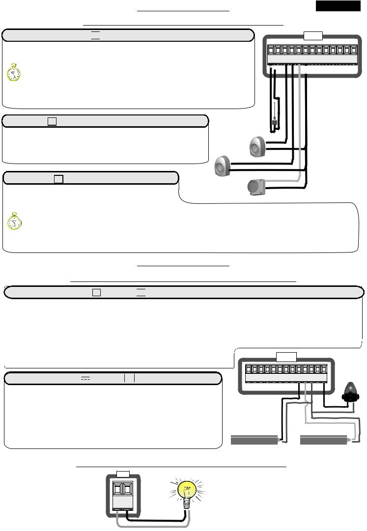
SAFETY LOOP |
|
CN1
1 |
2 |
3 |
4 |
5 |
6 |
7 |
8 |
9 10 11 12 13 |
- |
|
C1 |
|
|
C C2 C2 |
|
||
Safety exit loop
Connecting scheme of loop detector 1 reader
DRAWING SHOWS HOW TO
EVENTUALLY CONNECT THE
MAGNETIC LOOP
C1 = CONTACT OPEN
C2 = CONTACT CLOSED
12 = 24 V 


11 = 0 V 


7 = Contact photocell 1 (N.C.)
6 = Common
Shadow loop
Connecting scheme of loop detector 2 reader
8 = Contact photocell 2 (N.C.)
6 = Common
Note: Please set 98PHOTOCELL2 - LOOP2 menu to “Shadow loop”.
Free exit loop
Connecting scheme of loop detector reader
3 = Contact start (n.o.)
6 = Common
12 |
Safety exit |
11 |
loop 1 |
|
|
7 |
Loop1 |
|
|
6 |
Shadow |
|
|
|
loop |
8 |
Loop2 |
|
|
6 |
Free exit |
|
|
|
loop 3 |
3 |
Loop3 |
|
|
6 |
|
CONNECTING SCHEME OF THREE READERS OF MAGNETIC LOOP DETECTORS: (TWO OF THEM USED AS SECURITY DEVICE AND ONE AS EXIT)
SAFETY LOOP SYSTEM
SA |
|
FE |
|
L |
TY |
O |
|
OP |
|
S |
|
HA |
|
DO |
|
W |
|
O |
|
LOP |
|
38 |
|
EXIT LOOP SYSTEM
FR |
|
EE |
|
|
E |
LO |
XIT |
OP |
|
English
PRE SET PARAMETERS AND NO/NC CONTACTS
1 |
|
DISPLAY INPUTS STATUS |
||||||
|
|
Pratial |
|
|
Stop |
|||
Start |
|
opening |
|
|
|
|
Limit Switch |
|
|
|
|
|
|
|
|
|
opening motor 2 |
Limit |
|
|
|
|
|
|
Limit Switch |
|
|
|
SEA |
|
SET |
|
|||
Switch |
|
MENU |
|
|
|
closing motor 2 |
||
opening |
|
- - - |
|
|
|
|||
motor 1 |
|
|
|
|
||||
Limit |
|
- - - - |
|
|
||||
closing |
|
- - - - |
|
|
||||
Switch |
|
|
|
|
|
|
|
|
motor 1 |
Photocell 1 |
Edge 1 |
Edge 2 |
|||||
|
||||||||
|
|
Photocell 2 |
|
|
|
|||
|
|
|
|
|
|
|
|
N.C contacts |
|
|
|
SEA |
|
SET |
|
|
|
|
|
|
MENU |
|
When not engaged or not wired |
|||
- When N.C. (Photo, Stop, Limit switch and Edge) |
- |
|
|
|||||
|
|
|
|
|
|
|||
|
|
|
SEA |
|
SET |
|
|
|
|
|
|
MENU |
|
When cross photo or input is engaged |
|||
|
|
|
|
|
|
|||
|
|
|
|
|
|
|
|
|
MENU |
SEA |
N.O. contacts |
SET |
- When N.O. (Start, Partial opening) |
- |
When input is engaged |
|
|
MENU |
SEA |
|
|
|
|
SET |
When input is not engaged |
|
|
||
Power OFF |
|
|
|
||
2 |
|
|
|
|
|
OFF |
|
|
|
|
|
|
|
|
|
Power ON |
|
3 Keep pressed the two buttons |
and |
. |
At the same time put |
ON |
to start initialisation |
UP |
|
DOWN |
|
|
|
of the board until you see INIT on the display. |
|
|
|
||
4 |
|
SEA |
All parameters will return to the DEFAULT configuration, see "Default" column in the tables of the menus and |
MENU |
SET |
||
|
INIT |
all inputs will display their real state. |
|
|
|
|
|
|
MENU |
SEA |
All contacts N.C. are automatically turned off if not used (no segment on the display). |
4 |
SET |
||
|
|
||
|
|
If the contacts are connected, on the display they will appear in ON (lit segment). |
|
|
|
|
|
39
 Loading...