


®
Sistemi Elettronici
di Apertura Porte e Cancelli
International registered trademark n. 804888
English
GATE 1 DG R2BF
With inverter module
CONTROL UNIT FOR SLIDING GATES
(Cod. 23001235)
67411665 |
Rev.05 - 06/2016 |

® |
GATE 1 DG R2BF |
English |
|
Sistemi Elettronici |
INVERTER |
di Apertura Porte e Cancelli |
|
International registered trademark n. 804888 |
COMPONENTS
TECHNICAL SPECIFICATIONS
Control unit power supply: 230 Vac Single-phase
Absorption in stand by: 30 mA
Environment temperature : -20°C +50°C
+50°C 
Specifications of external enclosure: 183 X 238 X 120 - IP55
|
|
|
|
CN3 |
|
CN2 |
INTERFACE CARD |
|
|
|
|
|
|
COM SIGB |
SIGA |
|
F1 |
|
|
|
|
|
|
|
|
||
|
|
|
|
Tr1 |
R1 |
|
|
|
mm |
CMS |
|
|
|
|
|
|
CN5 |
|
|
|
RECEIVER RX |
155 |
CN4 |
EXP |
F2 |
|
|
|
|
|||||
|
|
|
|
CNP |
||
|
|
|
|
|
|
|
|
|
|
CNS |
|
|
JOLLY3 |
|
|
|
|
|
|
|
|
|
|
|
|
DS |
|
|
|
|
|
CNA |
|
|
|
|
|
|
|
|
JOLLY 3 |
|
|
|
CNS |
UP |
DOWN |
OK |
|
|
|
|
|
|
CN6 |
|
|
|
|
|
CN1 |
|
|
85 mm |
CN1 = Input/output connectors |
JOLLY 3 = Jolly 3 connector |
CN2 = Courtesy light connector |
DS = Programming display |
CN3 = Power connector |
CMS = Inverter interface connector |
CN4 = 24V~ connector |
OK = Programming button |
CN5 = Inverter control connector |
DOWN = Programming button |
CN6 = Limit switch connectors |
UP = Programming button |
CNA = Receiver connector RX |
R1 = Relay C motor command Courtesy light |
CNP = Programming connector |
F1 = 6.3AT fuse on 230V |
CNS = RF FIX Receiver connector |
F2 = Accessories 1A fuse |
EXP = Expansion module connector - |
Tr1 = Power transformer |
LSE card |
|
2

®
Sistemi Elettronici
di Apertura Porte e Cancelli
International registered trademark n. 804888
RADIO MODULE RF FIX (CNS)
RF FIX
Receiver connector
(Available from hardware revision R2)
|
English |
|
GATE 1 DG R2BF |
CONNECTIONS |
INVERTER |
||
|
|||
CN2
14 15 16 17 18 19 20
Flash Light |
Flash N |
CN4
24Vac Max 150 mA
24V (Red)
Limit switch Closing 1 (Yellow) Limit switch Opening 1 (Green)
Common (White)
Limit switch Closing 1 (Yellow) Limit switch Opening 1 (Green)
CN6 |
|
|
LIMIT |
1 |
SWITCH |
CN7 |
CN1
|
|
|
|
|
|
|
|
|
|
|
|
|
|
|
|
|
|
|
|
|
|
|
|
|
|
|
|
|
|
|
|
|
|
|
|
|
|
|
|
|
|
|
|
|
|
|
|
|
|
|
|
|
|
1 |
|
2 |
3 |
4 |
5 |
6 |
|
7 |
|
8 |
9 |
10 |
11 12 13 |
|||||||||||||
|
ANT |
COM START PEDST STOP COM |
PH1 |
PH2 EDGE 24VAUX COM 24V(FL) (FL)- |
||||||||||||||||||||||
+ |
- |
+ |
- |
Antenna |
Common |
Start |
START Pedestrian |
Stop |
Common |
Photocell 1 |
Photocell 2 |
Safety edge 1 |
AUX Programmable (24V 500 mA max) |
Common |
24V 500 mA max (Accessories) |
Flash (-) |
Nota: The connectors CN6 and CN7 are not used if the Four limit switch interface card is connected.
JUMPERS
WARNING: The control unit is designed with the automatic detection of not used N.C. inputs (Photocells, Stop and Limit switch) except the SAFETY EDGE input. The exclude inputs in self-programming can be restored in the “Check inputs” menu without need to repeat the programming (page 11).
CN1
Obligatory jumper without accessory connection.
Optional
1 |
2 |
3 |
4 |
5 |
6 |
7 |
8 |
9 |
10 |
11 12 13 |
ANT |
COM START PEDST STOP COM |
PH1 |
PH2 EDGE 24VAUX COM 24V(FL) (FL)- |
|||||||
+ |
- |
+ |
- |
Antenna |
Common |
Start |
START Pedestrian |
Stop |
Common |
Photocell 1 |
Photocell 2 |
Safety edge 1 |
AUX Programmable (24V 500 mA max) |
Common |
24V 500 mA max (Accessories) |
Flash (-) |
The herein reported f u n c t i o n s a r e available starting from: revision 01.07 c o m p a t i b l e w i t h JOLLY 3.
3
® |
GATE 1 DG R2BF |
English |
|
Sistemi Elettronici |
INVERTER |
di Apertura Porte e Cancelli |
|
International registered trademark n. 804888 |
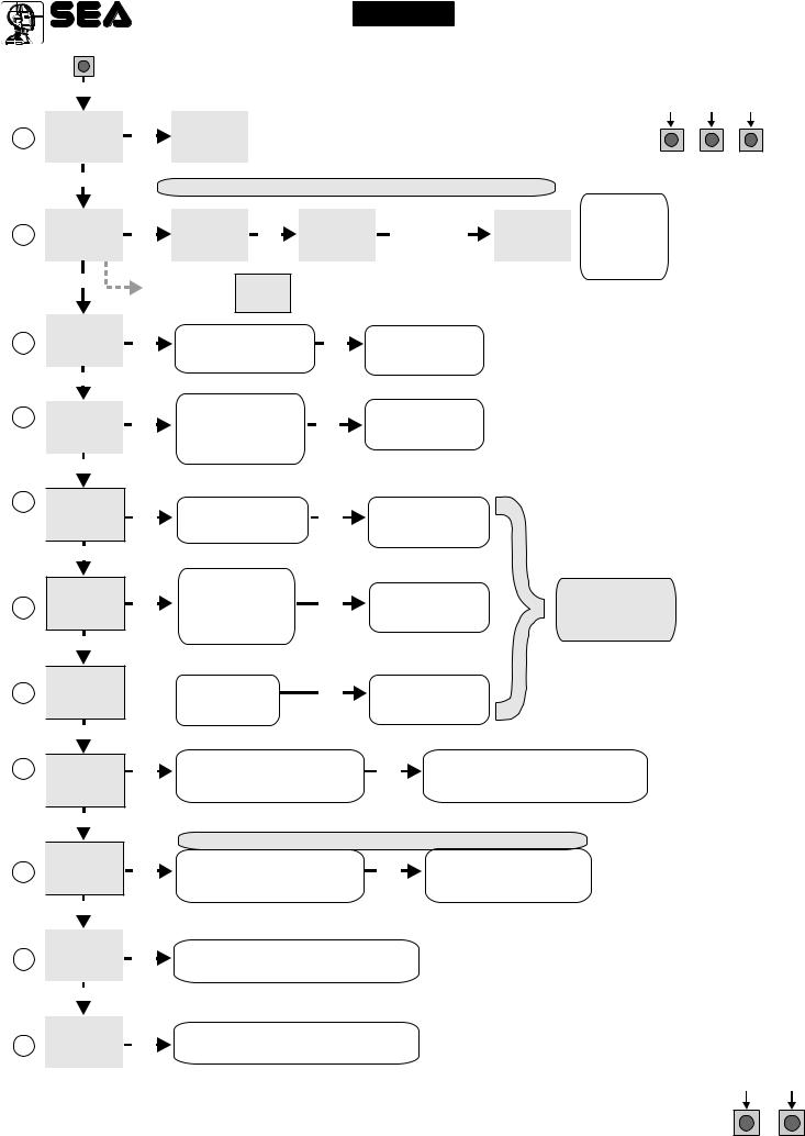
PROGRAMMING
UP
|
MENU |
SEA |
|
MENU |
SEA |
|
SET |
OK |
SET |
||
1 |
LANGUAGE |
ITALIANO |
|||
|
|
|
|
|
|
QUICK START
PROGRAMMING
BUTTONS
UP DOWN OK
|
|
UP |
|
|
Skip this step if you do not want to program a transmitter |
|
|
||||||
|
|
|
|
|
|
|
|||||||
|
|
|
|
|
|
|
|
|
|
Press the |
|
|
OK to exit |
|
MENU |
SEA |
|
MENU |
SEA |
SET |
|
SEA |
SET |
MENU |
SEA |
Menu or press |
|
2 |
SET |
|
|
|
MENU |
button of the |
SET |
||||||
TRANSMITTERS |
OK |
START |
|
OK |
PRESS |
|
STORED |
the button of |
|||||
|
|
TX to be |
|||||||||||
|
|
|
|
BUTTON |
the next TX to |
||||||||
|
|
|
|
|
|
|
|
|
|
stored |
|
|
be stored |
|
|
|
|
|
|
|
|
|
|
|
|
|
|
UP |
If on the display |
|
appears the item: |
SEA
MENU SET
RECEIVER MISSING
Check if a receiver has been connceted
(see page 2)
|
MENU |
SEA |
|
|
|
|
|
SET |
|
Choose the type of |
|
||
3 |
MOTOR |
OK |
OK To confirm and return |
|||
motor with |
||||||
|
|
|
|
UP or DOWN |
to main menu |
|
UP
|
|
SEA |
SET |
|
5 |
|
MENU |
OK |
|
|
REVERSE |
|||
|
|
|||
|
|
MOTOR |
|
|
|
|
|
|
|
|
|
UP |
|
|
6 |
|
SEA |
SET |
|
|
||||
|
MENU |
|||
|
LOGIC |
|
OK |
|
(See |
|
|
||
page 5) |
|
|
|
|
|
|
UP |
|
|
|
|
SEA |
SET |
|
|
|
MENU |
||
7PAUSE TIME OK
UP
|
SEA |
SET |
|
|
|
MENU |
|
||
8 |
START IN |
OK |
||
|
PAUSE |
|
||
|
UP |
|
|
|
|
SEA |
SET |
|
|
|
|
|||
9 |
MENU |
OK |
||
PROGRAM- |
||||
(See |
|
|||
page 5) |
MING |
|
|
|
|
UP |
|
|
|
|
SEA |
SET |
|
|
|
|
|||
|
MENU |
|
||
10 |
TEST START |
OK |
||
|
UP |
|
|
|
|
|
|
||
|
|
|
|
|
|
SEA |
SET |
|
|
|
MENU |
|
||
15 |
END |
|
OK |
|
|
|
|
|
|
|
UP |
|
|
|
|
|
|
|
|
|
SEA |
SET |
|
|
|
MENU |
|
||
16 |
SPECIAL |
OK |
||
|
MENU |
|
|
|
Choose ON with UP or DOWN
if you want to reverse the direction of
the motor rotation
With UP or DOWN choose
the desired logic
With UP or DOWN choose a delay for automatic closing
 With UP or DOWN Choose ON
OK |
Per confermare |
|
e tornare |
|
|
|
al Menu principale |
|
OK |
To confirm and return |
|
|
to main menu |
|
|
|
Skip this step |
OK |
To confirm and return |
if you want to work |
|
to main menu |
in half-automatic |
|
|
logic |
OK |
To confirm and return |
|
|
to main menu |
|
With UP or DOWN choose ON |
OK |
At the end of the selflearning |
the control unit returns automatically |
||
to start times learning |
|
to the main menu |
|
|
|
The gate will execute a CLOSING-OPENING-CLOSING CYCLE |
||
Skip this step if a TX has already been stored |
||
With |
OK |
To confirm and return to |
UP or DOWN Choose |
||
ON to start test |
|
main menu |
Press OK to return to the display of the inputs state.
Press OK to enter the special menu.
ALL OTHER PARAMETERS HAVE DEFAULT SETTINGS WHICH ARE USEFUL FOR THE 90% OF THE APPLICATIONS BUT CAN BE HOWEVER SET THROUGH THE SPECIAL MENU. FOR
ENTERING INTO THE SPECIAL MENU MOVE ON ONE OF THE MENU AND PRESS THE UP
DOWN UP
AND DOWN BUTTONS AT THE SAME TIME FOR 5 S.
4

® |
|
|
|
English |
|
GATE 1 DG R2BF |
||||
|
|
|
|
|
||||||
Sistemi Elettronici |
|
|
|
|
|
|
|
INVERTER |
||
di Apertura Porte e Cancelli |
|
|
|
|
|
|
|
|||
International registered trademark n. 804888 |
|
|
|
|
|
|
|
|||
|
|
|
|
|
|
|
||||
|
MENU FUNCTIONS TABLE GATE 1 DG R2BF |
|
|
|
|
|||||
MENU |
|
SET |
|
|
Description |
|
Default |
Set value |
|
|
|
|
|
|
|
|
|
|
|||
|
Italiano |
|
Italian |
|
|
|
|
|||
|
English |
|
English |
|
|
|
|
|||
1 - LANGUAGE |
Français |
|
French |
|
English |
|
|
|||
|
Español |
|
Spanish |
|
|
|
|
|||
|
Dutch |
|
Olandese |
|
|
|
|
|||
|
Start |
|
|
|
Start |
|
|
|
|
|
|
Pedestrian Start |
|
Pedestrian Start |
|
|
|
|
|||
|
External module |
|
External module |
|
Start |
|
|
|||
|
Stop |
|
|
|
Stop |
|
|
|
||
|
|
|
|
|
|
|
|
|||
2 - TRANSMITTERS |
|
|
|
|
Storing of a command |
|
Pedestrian |
|
|
|
|
Unloch |
|
for unlocking an |
|
|
|
||||
|
|
|
Start |
|
|
|||||
|
|
|
|
|
electric brake |
|
|
|
||
|
|
|
|
|
|
|
|
|
||
|
Delete a transmitter |
|
Delete single transmitter |
|
|
|
|
|||
|
Clear memory |
|
Delete transmitter memory |
|
|
|
||||
|
End |
|
|
|
“Transmitters” menu output |
|
|
|
||
|
Barrier |
|
Barrier |
|
|
|
|
|||
3 - MOTOR |
Centralina idraulica |
|
Hydraulics units |
|
|
|
|
|||
|
|
|
|
|
|
|
|
|
|
|
Lepus Fast |
|
Lepus Fast |
|
Barrier |
|
|
||||
For single-phase version only |
|
|
|
|
||||||
|
Big Fast - Super Fast |
|
Big Fast - Super Fast |
|
|
|
|
|||
|
Big |
|
|
|
Big |
|
|
|
|
|
3 - MOTOR |
Sliding |
|
Sliding |
|
Sliding |
|
|
|||
For three-phase version only |
Sliding Fast |
|
Sliding Fast |
|
|
|
||||
|
|
|
|
|
||||||
5 - REVERSE MOTOR |
Off |
|
|
|
Synchronized right motor |
|
Off |
|
|
|
On |
|
|
|
Synchronized left motor |
|
|
|
|||
|
|
|
|
|
|
|
|
|||
|
Automatic |
|
Automatic |
|
|
|
|
|||
|
Open-stop-close-stop-open |
Step by step type 1 |
|
|
|
|
||||
6 - LOGIC |
Open-stop-close-open |
|
Step by step type 2 |
|
Automatic |
|
|
|||
2 buttons |
|
Two buttons |
|
|
|
|||||
(See page 6) |
|
|
|
|
|
|||||
|
Safety |
|
Safety |
|
|
|
|
|||
|
Dead man |
|
Dead man |
|
|
|
|
|||
|
Off |
|
|
|
OFF |
|
|
|
|
|
7 - PAUSE TIME |
|
|
|
(semi-automatic logics) |
|
Off |
|
|
||
|
|
|
|
|
|
|
||||
1 240 |
|
|
Setting from 1s to 4min. |
|
|
|
||||
|
|
|
|
|
|
|
||||
8 - START IN PAUSE |
Off |
|
|
|
In pause start is not acceped |
Off |
|
|
||
On |
|
|
|
In pause start is accepted |
|
|
||||
|
|
|
|
|
|
|
||||
9 - PROGRAMMING |
Off |
On |
|
Times learning start |
|
Off |
|
|
||
(See page 6) |
|
|
|
|
||||||
|
|
|
|
|
|
|
|
|
|
|
10 - TEST START |
Off |
On |
|
Start command |
|
Off |
|
|
||
15 - END |
|
Press OK to return to the display of the firmware version |
|
|||||||
|
|
|
and to the one of inputs state. |
|
|
|
|
|||
|
|
|
|
|
|
|
|
|||
16 - SPECIAL MENU |
|
|
|
Press OK to enter the special menu. |
|
|||||
Note: In case of three-phase version, the motors are: “Sliding” and “Sliding Fast”.
5

® |
GATE 1 DG R2BF |
English |
|
Sistemi Elettronici |
INVERTER |
di Apertura Porte e Cancelli |
|
International registered trademark n. 804888 |
WORKING TIMES SELF LEARNING
1)Turn off electricity, release the motors and manually position the leaves on halfway. Reset the mechanical lock.
2)Connect the control board to the power supply.
3)Before starting the learing, make sure (through the test menu), that the relative limit switches of every opening are employed.
4)Select on the on-board display or JOLLY 3 programmer, the type of motor that you are using as indicated in the dispaly management.
5)If necessary also set the operation logic and the other parameters. If you want to program with a transmitter, store a transmitter before programming.
6)Select 9-PROGRAMMING on the display, press OK and than one of the UP or DOWN buttons.
(If the motor starts in opening, remove and re-put power supply, select on the display 5-REVERSE MOTOR.
And through the UP and DOWN button put it on ON, or if you have the Jolly 3 programmer, activate the motor exchange function. )
7) At this point the gate will start the following cycle: CLOSING - OPENING - CLOSING.
FUNCTION LOGIC
AUTOMATIC LOGIC
A start impulse opens the gate. A second impluse during the opening will not be accepted. A start impulse during closing reverses the movement.
NOTE 1: To have the automatic closing it is necessary to set a pause time, otherwise all the logic will be semiautomatic.
NOTE2: It is possible to choose, whether to accept or not, the start in pause, selecting in the MENU the item 8-START IN PAUSE and choosing ON or OFF. By default, the parameter is OFF.
SECURITY LOGIC
A start impulse opens the gate. A second impulse during opening reverses the movement. A start impulse during closing reverses the movement.
NOTE 1: To have the automatic closing it is necessary to set a pause time, otherwise all the logic will be semiautomatic.
NOTE2: It is possible to choose, whether to accept or not, the start in pause, selecting in the MENU the item 8-START IN PAUSE and choosing ON or OFF. By default, the parameter is OFF.
STEP BY STEP TYPE 1 LOGIC
The start impulse follows the OPEN-STOP-CLOSE-STOP-OPEN logic.
NOTE 1: To have the automatic closing it is necessary to set a pause time, otherwise all the logic will be semiautomatic.
NOTE2: It is possible to choose, whether to accept or not, the start in pause, selecting in the MENU the item 8-START IN PAUSE and choosing ON or OFF. By default, the parameter is OFF.
STEP BY STEP TYPE 2 LOGIC
The start impulse follows the OPEN-STOP-CLOSE -OPEN logic.
NOTE 1: To have the automatic closing it is necessary to set a pause time, otherwise all the logic will be semiautomatic.
NOTE2: It is possible to choose, whether to accept or not, the start in pause, selecting in the MENU the item 8-START IN PAUSE and choosing ON or OFF. By default, the parameter is OFF.
DEAD MAN LOGIC
The gate opens as long as the START button of opening is pressed; releasing it the gate stops. The gate closes as long as the button connected to the PEDESTRIAN START is pressed; releasing it the gate stops. To execute complete opening and/or closing cycles the related pushbuttons must be constantly pressed.
2 PUSHBUTTONS LOGIC
One start opens, one pedestrian start closes. In opening the closing will not be accepted. In closing a start command reopens, a pedestrian start command (closes) will be ignored.
6
® |
GATE 1 DG R2BF |
English |
|
Sistemi Elettronici |
INVERTER |
di Apertura Porte e Cancelli |
|
International registered trademark n. 804888 |
SPECIAL MENU
PRESS AT THE SAME TIME FOR 5 SECONDS TO ENTER OR TO EXIT THE SPECIAL MENU
DOWN UP
SPECIAL MENU FUNCTIONS TABLE GATE 1 DG R2BF INVERTER
For entering into the special menu move on one of the menu and press the UP and DOWN buttons at the same time for 5 s. For exiting the special menu press END or move on one of the menu and press the UP and DOWN buttons at the same time for 5 s.
|
MENU SP |
|
|
SET |
Description |
Default |
Set Value |
|
|
|
|
|
|
|
|
17 - OPENING SPEED |
10 |
|
100 |
Setting from 10 to 100 |
80 |
|
|
18 - CLOSING SPEED |
10 |
|
100 |
Setting from 10 to 100 |
80 |
|
|
21 - OPENING SLOWDOWN |
10 60 from max. speed |
Slowdown speed in opening |
20 |
|
|||
|
SPEED 1 |
|
|||||
|
|
|
|
|
|
|
|
22 - CLOSING SLOWDOWN |
10 60 from max. speed |
Slowdown speed in closing |
20 |
|
|||
|
SPEED 1 |
|
|||||
|
|
|
|
|
|
|
|
28 - OPENING A THRESHOLD * |
1 |
- |
5 |
Adjust inversion current on |
2.5 |
|
|
For three-phase version only |
motors in opening. |
|
|||||
|
|
|
|
|
|||
29 - CLOSING A THRESHOLD * |
1 |
- |
5 |
Adjust inversion current on |
2.5 |
|
|
For three-phase version only |
motors in closing. |
|
|||||
32 - ENCODER * |
Potentiometer |
Enables the reading of the |
Off |
|
|||
potentiometer with LE card. |
|
||||||
|
|
|
|
|
|
|
|
|
|
|
|
|
Reports the current position |
|
|
|
|
- - - - - - - - |
of the potentiometer on the |
|
|
||
|
51 - I.PAR.M1 * |
leaf. This parameter is useful |
|
|
|||
|
|
|
|
|
for seeing if the potentiometer |
|
|
|
|
|
|
|
is read correctly. |
|
|
|
|
|
|
|
Reports the impulses |
|
|
|
52 - I.AP.M1 * |
- - - - - - - - |
stored by the control unit |
|
|
||
|
|
|
|
|
when the leaf is fully open. |
|
|
|
|
|
|
|
Reports the impulses stored |
|
|
|
53 - I.CH.M1 * |
- - - - - - - - |
by the control unit when the |
|
|
||
|
|
|
|
|
leaf of is fully close. |
|
|
32 - ENCODER * |
On |
|
|
In ON enables the Encoder |
Off |
|
|
|
|
|
|
|
|
|
|
|
47 - ENCODER PAR.1 * |
xxx. |
|
Encoder impulses during operation (Motor 1). |
|||
|
48 - ENCODER TOT.1 * |
xxx. |
|
Encoder impulses stored in programming (Motor 1). |
|||
32 - ENCODER * |
Off |
|
|
In OFF disabled the Encoder |
Off |
|
|
|
|
10% (Fast intervention) |
Adjusts the intervention time |
|
|
||
33 - OPENING SENSITIVITY |
99% (Slow intervention) |
of the Encoder / Potentiometer |
95 |
|
|||
in opening |
|
||||||
|
MOTOR1 |
|
|
|
|
||
|
Off (Intervention excluded) |
Disabled |
|
|
|||
|
|
|
|
||||
|
|
10% (Fast intervention) |
Adjusts the intervention time |
|
|
||
34 - CLOSING SENSITIVITY |
99% (Slow intervention) |
of the Encoder / Potentiometer |
95 |
|
|||
|
MOTOR1 |
|
|
|
in closing |
|
|
|
Off (Intervention excluded) |
Disabled |
|
|
|||
|
|
|
|
||||
57 - WORKING CURRENT |
0.0A |
|
Shows motor absorption |
|
|
||
|
during operation |
|
|
||||
|
|
|
|
|
|
|
|
|
|
|
|
|
From OFF to 50% of |
|
|
59 - OPENING SLOWDOWN 1 |
Off |
|
50 |
the stroke. Note: Not active |
30 |
|
|
|
if the Four limit switch |
|
|||||
|
|
|
|
|
|
|
|
|
|
|
|
|
interface card is present |
|
|
|
|
|
|
|
From OFF to 50% of |
|
|
60 - CLOSING SLOWDOWN 1 |
Off |
|
50 |
the stroke. Note: Not active |
30 |
|
|
|
if the Four limit switch |
|
|||||
|
|
|
|
|
|
|
|
|
|
|
|
|
interface card is present |
|
|
7

® |
GATE 1 DG R2BF |
English |
|
Sistemi Elettronici |
INVERTER |
di Apertura Porte e Cancelli |
|
International registered trademark n. 804888 |
MENU SP |
SET |
Description |
Default |
Set Value |
0 % |
|
Adjust the passage |
50% |
|
63 - DECELERATION |
|
between normal speed |
|
|
100% |
|
and slowdown speed |
|
|
1 s |
|
Acceleration ramp. |
2.5 s |
|
64 - ACCELERATION |
|
Adjusts the motor start. |
|
|
5 s |
|
|
|
70 - POSITION RECOVERY |
|
Retrieves the inertia of the |
1 s |
|
|
0 20 s |
motor in opening and closing |
|
|||
(For three-phase version only) |
|
after Stop or reversing |
|
|
|
|
|
|
|
||
|
Only opening |
If you force the gate |
|
|
|
|
Only closing |
manually, the control |
|
Off |
|
79 - ANTI INTRUSION |
|
unit starts the motor to |
|
|
|
Opening and closing |
|
||||
|
restore the state of the |
|
|
|
|
|
Off |
gate before forcing. |
|
|
|
|
|
|
|
|
|
|
Only closing |
Pre-flashing only |
|
|
|
85 - PREFLASHING |
active before closing |
|
Off |
|
|
|
|
|
|||
0.0 5.0 |
Pre-flashing time |
|
|
||
|
|
|
|
||
|
Normal |
Normal |
|
|
|
86 - FLASHING LIGHT |
Light |
Control lamp |
|
Normal |
|
Always |
Always ON |
|
|
||
|
|
|
|||
|
|
|
|
||
|
Buzzer |
Buzzer |
|
|
|
|
|
The flashing light remains |
|
|
|
|
Off |
OFF with the active timer |
|
|
|
87 - FLASHING LIGHT |
|
and open gate |
|
Off |
|
AND TIMER |
On |
The flashing light remains |
|
|
|
|
|
|
|||
|
ON with active timer and |
|
|
|
|
|
|
open gate |
|
|
|
|
In cycle |
Courtesy light in cycle |
|
20 |
|
88 - COURTESY LIGHT |
|
|
|
|
|
1 240 |
Courtesy light setting |
|
|
||
|
from 1s to 4min. |
|
|
|
|
|
|
|
|
|
|
|
|
When setting this function |
|
|
|
89 - TRAFFIC LIGHT |
|
the pedestrian input will be |
|
|
|
Off on |
activated to work on the |
|
Off |
|
|
RESERVATION |
|
auxiliary board SEM |
|
|
|
|
|
(traffic light management). |
|
|
|
90 - PARTIAL OPENING |
5 100% |
Setting from 5 to 100 |
|
100% |
|
|
= Start |
Pause in partial opening |
|
|
|
|
same as in total opening |
|
|
|
|
91 - PARTIAL PAUSE |
|
|
= Start |
|
|
Off |
Disabled |
|
|
||
|
|
|
|
|
|
|
1 240 |
Setting from 1s to 4 min. |
|
|
|
|
Off |
Transforms the selected |
|
|
|
92 - TIMER |
|
input in an input on |
|
|
|
On photo2 |
|
Off |
|
||
which to connect an |
|
|
|||
|
|
|
|
||
|
On pedestrian entry |
external clock. |
|
|
|
|
Off |
Disabled |
|
|
|
93 - FIRE SWITCH |
On photo2 |
Active on Photo 2 |
|
Off |
|
|
On pedestrian entry |
Active on pedestrian |
|
|
|
8
 Loading...