


®
Sistemi Elettronici |
|
|
di Apertura Porte e Cancelli |
Italiano |
|
International registered trademark n. 804888 |
||
|
||
|
|
|
|
English |
|
|
|
|
GATE 2 DG R1 |
Français |
|
|
||
Español |
||
|
(Cod. 23023025)
CENTRALE ELETTRONICA PER 1 O 2 MOTORI A 230V/115V ELECTRONIC CONTROL UNIT FOR 1 OR 2 230V/115V MOTORS ARMOIRE DE COMMANDE POUR 1 OU 2 MOTEURS EN 230V/115V CENTRAL ELECTRÓNICA PARA 1 O 2 MOTORES A 230V/115V
SEA S.p.A.
Zona industriale 64020 S.ATTO Teramo - (ITALY)
Tel. +39 0861 588341 r.a. Fax +39 0861 588344
www.seateam.com
seacom@seateam.com
67411385 |
Rev.07 - 12/2014 |
®
English |
GATE 2 DG R1 |
Sistemi Elettronici
di Apertura Porte e Cancelli
International registered trademark n. 804888
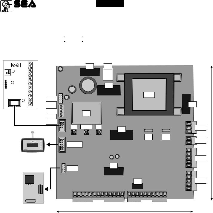
COMPONENTS
TECHNICAL SPECIFICATIONS
Control unit power supply: 230 Vac 50/60 Hz - 115Vac 50/60 Hz
Absorption in stand by: 30 mA
Environment temperature : -20°C +50°C
+50°C 
Specifications of external enclosure: 325,7 X 246 X 140
CNP
LE CARD
|
- |
+ |
M2 |
ENCON |
|
|
1011 |
1 |
2 |
|
9 |
|
7 8 |
||
POT |
DS1 |
|
|
|
|
|
|
|
|
|
6 |
|
|
|
5 |
|
|
|
4 |
|
|
|
3 |
CN1 |
|
|
1 2 |
|
|
|
M1 |
P01 D1 P11 P02 D2 P12 I1 I2 GND I3 I4
F1 R4
|
R2 |
|
CNP |
TR1 |
|
|
F2 |
|
|
|
|
CN7 |
DS |
|
|
|
|
EXP |
UP DOWN OK |
|
|
CN6 |
|
|
R1 |
|
|
T1 |
T2 |
|
JOLLY |
CN5 |
|
|
JOLLY-JOLLY2
RECEIVER RX
CN4
F3
CNA
R3 |
CN3 |
CN1 |
|
CN2 |
|
174 mm |
|
|
CN1 = Input/output connectors |
OK = Programming button |
||
CN2 = Limit switch, 24V~, Electrolock connector |
DOWN = Programming button |
||
CN3 = M1 Motors and capacitors connector |
UP = Programming button |
||
CN4 = M2 motors and capacitors connector |
T1 |
= Motors piloting Triac |
|
CN5 = Courtesy light output connector |
T2 |
= Motors piloting Triac |
|
CN6 = Power supply connector |
R1 |
= Motors comand relay |
|
CN7 = Encoder connector |
R2 |
= Courtesy light comand relay |
|
CNA = RX Receiver connector |
R3 |
= Photocell autotest relay |
|
CNP = Porgramming connector |
R4 |
= Electrolock relay |
|
EXP = Expansion module connector / LE Card |
F1 |
= Accessories 1A fuse |
|
JOLLY = Jolly and Jolly 2 connector |
F2 |
= 6.3AT fuse on 230V/10AT on 115V |
|
DS = Programming display |
F3 |
= 6.3A Electrolock fuse |
|
|
TR1 = Power transformer |
||
168 mm
24 |
67411385 |
Rev.07 - 12/2014 |

® |
English |
GATE 2 DG R1 |
|
Sistemi Elettronici |
|||
|
|
||
di Apertura Porte e Cancelli |
CONNECTIONS |
|
|
International registered trademark n. 804888 |
|
||
CN2 |
CN4 |
||
CN3 |
14 15 |
16 17 |
18 |
19 |
20 21 |
22 23 |
||
LSO1 LSC1 LSO2 LSC2 COM |
24V~ 24VPH |
LOCK |
|||||
Limit Switch opening M1 |
Limit Switch closing M1 |
Limit Switch opening M2 |
Limit Switch closing M2 |
Common |
24V~ (800 mA max) |
24VPh (800 mA max) |
Electrolock |
|
|
|
|
|
|
|
|
|
|
|
|
|
|
|
|
|
|
|
|
|
|
|
|
|
|
|
|
|
|
|
|
|
|
|
|
|
|
|
|
|
|
|
|
|
|
|
|
|
|
|
|
|
|
|
|
|
|
|
|
|
|
|
|
|
|
|
|
|
|
|
|
|
|
|
24 25 |
26 27 28 |
|
29 30 |
31 32 |
|
|
33 |
||||||||||||||||||||||||||||
|
CLM1 NM1 OPM1 |
CAPM1 |
|
CLM2 NM2 OPM2 |
CAPM2 |
|||||||||||||||||||||||||||||||
Motor 1 closing |
|
|
Motor 1 Neutral |
|
|
Motor 1 opening |
|
|
|
|
|
|
|
Motor 2 closing |
|
|
Motor 2 Neutral |
|
Motor 2 opening |
|
|
|
|
|
|
|
||||||||||
|
|
Capacitor Motor 1 |
|
|
|
Capacitor Motor 2 |
||||||||||||||||||||||||||||||
|
|
|
|
|
|
M1 |
|
|
|
|
|
|
|
|
|
|
|
|
|
|
|
|
M2 |
|
|
|
|
|
|
|
|
|
|
|
||
CN1
1 |
2 |
3 |
4 |
5 |
6 |
7 |
8 |
9 |
10 |
11 12 13 |
||
ANT |
COM STRT STPD |
STOP COM PH1 |
PH2 |
EDG1 EDG2 |
COM |
24VA |
FLS |
|||||
|
|
|
|
|
|
|
|
|
|
- |
+ |
|
Antenna |
Common |
Start |
START Pedestrian |
Stop |
Common |
Photocell 1 |
Photocell 2 |
Safety edge 1 |
Safety edge 2 |
Common |
AUX (24V 800mA max) |
Lamp (500mA max) |
JUMPERS
WARNING: The control unit is designed with the automatic detection of not used N.C. inputs (Photocells, Stop and Limit switch) except the SAFETY EDGE input. The exclude inputs in self-programming can be restored in the “Check inputs” menu without need to repeat the programming (page 38).
CN1
Obligatory jumper without accessory connection.
Optional
|
|
|
|
|
|
|
|
|
|
|
|
|
|
|
|
|
|
|
|
|
|
|
|
|
|
|
|
|
|
|
|
|
|
|
|
|
|
|
|
|
|
|
|
|
|
|
|
|
|
|
|
|
|
1 |
2 |
3 |
4 |
|
5 |
6 |
|
7 |
8 |
9 |
10 |
11 12 13 |
||||||||||||||
ANT |
COM STRT STPD |
STOP COM |
PH1 |
PH2 |
EDG1 EDG2 |
COM |
24VA |
FLS |
|
|
|
|
|
|
- |
+ |
|
Antenna |
Common |
Start |
START Pedestrian |
Stop |
Common |
Photocell 1 |
Photocell 2 |
Safety edge 1 |
Safety edge 2 |
Common |
AUX (24V 800mA max) |
Lamp (500mA max) |
The herein reported f u n c t i o n s a r e available starting from revision 33, on R1B versions only.
67411385 |
Rev.07 - 12/2014 |
25 |

®
English |
GATE 2 DG R1 |
Sistemi Elettronici
di Apertura Porte e Cancelli
International registered trademark n. 804888
PROGRAMMING
QUICK START
UP
SEA
MENU SET
1 LANGUAGE
UP
SEA
MENU SET
2
TRANSMITTERS
|
UP |
|
|
SEA |
SET |
|
MENU |
|
3 |
MOTOR |
|
|
UP |
|
|
SEA |
SET |
|
MENU |
|
4 |
ONE SINGLE |
|
|
LEAF |
|
|
UP |
|
5 |
SEA |
SET |
MENU |
||
|
|
|
LOGIC
(See page 27)
UP
SEA
MENU SET
6 PAUSE TIME
|
UP |
|
|
|
SEA |
SET |
|
|
MENU |
||
7 |
START IN |
||
|
PAUSE |
||
|
UP |
|
|
8 |
SEA |
SET |
|
MENU |
|||
PROGRAM- |
|||
(See |
|||
page 27) |
MING |
|
|
|
UP |
|
|
|
SEA |
SET |
|
|
MENU |
||
9 |
TEST START |
||
|
|
|
|
|
|
|
|
|
|
|
|
|
|
PROGRAMMING |
||
|
|
|
|
|
|
|
|
|
|
|
|
BUTTONS |
||||
|
MENU |
|
SEA |
|
|
|
|
|
|
|
|
|||||
OK |
|
|
|
SET |
|
|
|
|
|
|
|
|
|
|
|
|
ITALIANO |
|
|
|
|
|
|
|
|
|
|
|
|||||
|
|
|
|
|
|
|
|
|
|
|
|
|||||
|
|
|
|
|
|
|
|
|
|
|
|
|
|
UP |
DOWN |
OK |
|
|
|
|
|
|
|
|
|
|
|
|
|
|
|||
|
|
Skip this step if you do not want to program a transmitter |
|
|
||||||||||||
|
|
|
|
|
|
|
|
|
|
|
|
|
Press the |
|
|
OK to exit |
|
MENU |
|
SEA |
|
|
|
|
SEA |
SET |
|
MENU |
SEA |
Menu or press |
|||
|
|
|
|
SET |
|
|
|
|
MENU |
|
button of the |
SET |
||||
OK |
START |
|
OK |
|
PRESS |
|
|
STORED |
the button of |
|||||||
|
|
|
|
TX to be |
||||||||||||
|
|
|
|
|
BUTTON |
|
the next TX to |
|||||||||
|
|
|
|
|
|
|
|
|
|
|
stored |
|
|
|||
|
|
|
|
|
|
|
|
|
|
|
|
|
|
|
be stored |
|
|
|
|
|
|
|
|
|
Check if a receiver has |
|
|
|
|||||
|
|
|
|
|
|
|
|
|
|
|
||||||
If on the display |
|
|
SEA |
|
|
|
|
|
||||||||
|
|
MENU SET |
|
|
|
|
||||||||||
|
|
RECEIVER |
|
been connceted |
|
|
|
|
|
|
||||||
appears the item: |
|
|
|
|
|
|
|
|
||||||||
|
MISSING |
|
|
(see page 24) |
|
|
|
|
|
|
||||||
|
|
|
|
|
|
|
|
|
|
|
|
|
||||
OK |
Choose the type of |
To confirm and return |
|
|
|
|||||||||||
|
|
|
|
motor with |
|
OK |
|
|
|
|||||||
|
|
|
|
|
UP or DOWN |
|
|
|
|
to main menu |
|
|
|
|||
|
|
|
|
|
|
|
|
|
|
|
|
|
||||
|
|
|
|
|
Skip this step if you are working in double leaf mode |
|
|
|||||||||
OK |
With UP or DOWN choose |
OK |
To confirm and return |
|
||||||||||||
|
|
|
ON only if in single |
|
||||||||||||
|
|
|
to the main menu |
|
||||||||||||
|
|
|
leaf mode (Motor 1) |
|
|
|
||||||||||
|
|
|
|
|
|
|
|
|
||||||||
With UP or DOWN OK 
 choose
the desired logic
With UP or DOWN OK choose a delay for automatic closing
OK 
 With UP or DOWN Choose ON
OK |
To confirm and return |
|
to main menu |
OK |
To confirm and return |
|
to main menu |
OK |
To confirm and return |
|
to main menu |
Skip this step
if you want to work
in half-automatic
logic
OK |
With UP or DOWN choose ON |
OK |
At the end of the selflearning |
the control unit returns automatically |
|||
|
to start times learning |
|
to the main menu |
|
|
|
|
|
The gate will execute a CLOSING-OPENING-CLOSING CYCLE |
||
|
Skip this step if a TX has already been stored |
||
OK |
With |
OK |
To confirm and return to |
UP or DOWN Choose |
|||
|
ON to start test |
|
main menu |
ALL OTHER PARAMETERS HAVE DEFAULT SETTINGS WHICH ARE USEFUL FOR THE 90% OF THE APPLICATIONS 
 BUT CAN BE HOWEVER SET THROUGH THE SPECIAL MENU. FOR ENTERING INTO THE SPECIAL MENU MOVE
 ON ONE OF THE MENU AND PRESS THE UP AND DOWN BUTTONS AT THE SAME TIME FOR 5 S. DOWN UP
26 |
67411385 |
Rev.07 - 12/2014 |

®
English |
GATE 2 DG R1 |
Sistemi Elettronici
di Apertura Porte e Cancelli
International registered trademark n. 804888
MENU FUNCTIONS TABLE GATE 2 DG R1
MENU
1 - langvage
2 - trans |
U |
tters |
|
3 - |
U |
otor |
|
4 - one s  ngle leaf *
5 - log (
(
(See page 29)
6 - paVse t |
U |
e |
|
7 - start  n pavse
UU |
ng |
8 - progra |
|
(See page 28) |
|
9 - test start
end
SET
 tal
tal ano
ano
engl sk
sk
fran(a  s
s
espanol
dut(k
start
Pedestr an Start
External |
U |
odvle |
|
||
stop |
|
|
vnlo(k |
|
|
|
|
U |
Delete a trans itter
Description |
Default |
Set value |
Italian |
|
|
English |
|
|
French |
tal ano |
|
Spanish |
|
|
Olandese |
|
|
Start |
|
|
Pedestrian Start |
|
|
External module |
|
|
Stop |
start |
|
Storing of a command |
Ped Start. |
|
for unlocking an |
|
|
|
|
|
electric brake |
|
|
Delete single transmitter |
|
|
(Lear |
UU |
Delete transmitter memory |
|
|
|
|
e ory |
|
|
|
|
||
kydravli( |
Hydraulic |
|
|
|
|
|
Sl d ng |
Sliding |
|
U |
|
||
|
|
|
|
|
||
|
|
|
|
|
||
Reuers ble Sl d ng gate Reversible sliding gate |
|
E(kan ( |
|
|||
|
|
|
|
|||
U |
|
Mechanic |
|
|
|
|
E(kan ( |
|
|
|
|
||
off |
|
Disabled |
|
|
|
|
|
|
|
|
off |
|
|
on |
|
In ON activates single leaf |
|
|
||
|
mode (Motor 1) |
|
|
|
|
|
|
|
|
|
|
|
|
U |
|
Automatic |
|
|
|
|
Avto at ( |
|
|
|
|
||
open-stop-(lose-stop-open Step by step type 1 |
|
|
|
|
||
open-stop-(lose-open |
Step by step type 2 |
|
|
|
|
|
|
|
|
|
U |
|
|
|
|
|
|
|
||
2 bvttons |
Two buttons |
|
Avto at ( |
|
||
|
|
|
|
|||
safety |
Safety |
|
|
|
|
|
|
|
|
|
|
|
|
DeadUan |
Dead man |
|
|
|
|
|
|
|
|
|
|
|
|
off |
|
OFF |
|
|
|
|
|
(semi-automatic logics) |
|
off |
|
||
|
|
|
|
|||
1 240 |
|
Setting from 1s to 4min. |
|
|
|
|
|
|
|
|
|
|
|
off |
|
In pause start is not acceped |
|
off |
|
|
on |
|
In pause start is accepted |
|
|
||
|
|
|
|
|
||
|
|
|
|
|
|
|
Off on |
Times learning start |
|
off |
|
|
|
Off on |
Start command |
|
off |
|
|
|
|
|
|
|
|||
|
Select END and press OK to exit the menu.The menu |
|
||||
|
deactivates automatically after 2 minutes |
|
||||
|
|
|
|
|
|
|
Note 1: The * indicates that the default value or the menu may change depending on the selected motor type.
67411385 |
Rev.07 - 12/2014 |
27 |

®
English |
GATE 2 DG R1 |
Sistemi Elettronici
di Apertura Porte e Cancelli
International registered trademark n. 804888
WORKING TIMES SELF LEARNING
The control unit is pre-set with the default settings, to start the control unit with the
DEFAULT settings just keep pressed the UP and DOWN buttons at the same time power
supplying the control unit the display shows the message init.
The DEFAULT settings are shown in the Menues table.
WORKING TIMES SELFLEARNING THROUGH IMPULSES
ATTENTION: This procedure is potentially dangerous and should only be performed by qualified people in safety conditions.
NOTE: The card is preset with the standard working times, therefore the automation can be started even without the times programming, simply by adjusting the timing on the display (see default times).
1)Turn off electricity, release the motors and manually position the leaves on halfway.
Reset the mechanical lock.
2)Connect the control board to the power supply
3)Select on the on-board display or JOLLY programmer, the type of motor that you are using as indicated in the dispaly management ( UE(kani( - Ele(trokydravli(, etc).
4)If necessary also set the operation logic and the other parameters. If you want to program with a transmitter, store a transmitter before programming.
5) Select PROGra |
UU |
ing on the display, press OK and than one of the UP or DOWN buttons. |
|
|
(If the motor starts in opening, remove and re-put power supply, select on the display reuerse |
U |
otor. And through |
||
|
||||
the UP and DOWN button put it on ON, or if you have the Jolly programmer, activate the motor exchange function. )
6)At this point the gate will start the following cycle: CLOSING M2 - CLOSING M1 - OPENING M1 - OPENING M2 - CLOSING M2 - CLOSING M1. During cycle, to store the respective stops, press UP or DOWN or START at every point of stop of the leaf.
7)The self-learning is done.
SELFLERNING OPERATION TIME WITH ENCODER / POTENTIOMETER
When an encoder is installed, it is necessary to select On in the EN(oder menu, when the potentiometer is installed, it is necessary to select POTENtioUeter in the EN(oder menu. Start programming and make sure that leaf 2 starts as first in closing. The gate will automatically execute the following cycle: CLOSING M2 - CLOSING M1 - OPENING M1 - OPENING M2 - CLOSING M2 - CLOSING M1.
Note: For stop detection sensitivity setting refer to the special menu.
SELFLEARNING OPERATION TIME WITH AMPEROMETRIC SENSOR (For electromechanical motors only)
The times learning can be done only on electromechanical gates, taking advantage of the automatic detection of the stops.
Once the programming has been started just make sure that the gate executes the following cycle: CLOSING M2 - CLOSING M1 - OPENING M1 - OPENING M2 - CLOSING M2 - CLOSING M1.
Note: For stop detection sensitivity setting refer to the special menu.
LEARNING WITH LIMIT SWITCH
When limit switches are mounted, the gate executes automatically the follwing cycle: CLOSING M2 - CLOSING M1 - OPENING M1 - OPENING M2 - CLOSING M2 - CLOSING M1.
Before starting the learning, make sure( through the test menu), that the relative limit switches of every leaf and every opening are employed.
Exe: For the M2 motor closing the limit switch M2 in closing must be employed.
28 |
67411385 |
Rev.07 - 12/2014 |

®
English |
GATE 2 DG R1 |
Sistemi Elettronici
di Apertura Porte e Cancelli
International registered trademark n. 804888
FUNCTION LOGIC
AUTOMATIC LOGIC
A start impulse opens the gate. A second impluse during the opening will not be accepted. A start impulse during closing reverses the movement.
NOTE 1: To have the automatic closing it is necessary to set a pause time, otherwise all the logic will be semiautomatic.
NOTE2: It is possible to choose, whether to accept or not, the start in pause, selecting in the MENU the item Startin pavse and choosing ON or OFF. By default, the parameter is OFF.
SECURITY LOGIC
A start impulse opens the gate. A second impulse during opening reverses the movement. A start impulse during closing reverses the movement.
NOTE 1: To have the automatic closing it is necessary to set a pause time, otherwise all the logic will be semiautomatic.
NOTE2: It is possible to choose, whether to accept or not, the start in pause, selecting in the MENU the item Startin pavse and choosing ON or OFF. By default, the parameter is OFF.
STEP BY STEP TYPE 1 LOGIC
The start impulse follows the OPEN-STOP-CLOSE-STOP-OPEN logic.
NOTE 1: To have the automatic closing it is necessary to set a pause time, otherwise all the logic will be semiautomatic.
NOTE2: It is possible to choose, whether to accept or not, the start in pause, selecting in the MENU the item Startin pavse and choosing ON or OFF. By default, the parameter is OFF.
STEP BY STEP TYPE 2 LOGIC
The start impulse follows the OPEN-STOP-CLOSE -OPEN logic.
NOTE 1: To have the automatic closing it is necessary to set a pause time, otherwise all the logic will be semiautomatic.
NOTE2: It is possible to choose, whether to accept or not, the start in pause, selecting in the MENU the item Startin pavse and choosing ON or OFF. By default, the parameter is OFF.
DEAD MAN LOGIC
The gate opens as long as the START button of opening is pressed; releasing it the gate stops. The gate closes as long as the button connected to the PEDESTRIAN START is pressed; releasing it the gate stops. To execute complete opening and/or closing cycles the related pushbuttons must be constantly pressed.
2 PUSHBUTTONS LOGIC
One start opens, one pedestrian start closes. In opening the closing will not be accepted. In closing a start command reopens, a pedestrian start command (closes) will be ignored.
67411385 |
Rev.07 - 12/2014 |
29 |

®
English |
GATE 2 DG R1 |
Sistemi Elettronici
di Apertura Porte e Cancelli
International registered trademark n. 804888
SPECIAL MENU
PRESS AT THE SAME TIME FOR 5 SECONDS TO ENTER OR TO EXIT THE SPECIAL MENU
DOWN UP
SPECIAL MENU FUNCTIONS TABLE GATE 2 DG R1
For entering into the special menu move on one of the menu and press the UP and DOWN buttons at the same time for 5 s. For exiting the special menu press END or move on one of the menu and press the UP and DOWN buttons at the same time for 5 s.
MENU SP |
|
SET |
Description |
Default |
Set value |
|||
|
|
|
|
|
|
|
|
|
|
|
|
|
|
|
M1 opening torque |
|
|
1 - open ng torq 1 * |
10 |
100 |
Note: with hydraulic motors |
75 |
|
|||
|
|
|
|
|
|
the torque will be on 100% |
|
|
|
|
|
|
|
|
M1 closing torque |
|
|
2 - (los ng torq 1 * |
10 |
100 |
Note: with hydraulic motors |
75 |
|
|||
|
|
|
|
|
|
the torque will be on 100% |
|
|
|
|
|
|
|
|
M2 opening torque |
|
|
3 - open ng torq 2 * |
10 |
100 |
Note: with hydraulic motors |
75 |
|
|||
|
|
|
|
|
|
the torque will be on 100% |
|
|
|
|
|
|
|
|
M2 closing torque |
|
|
4 - (los ng torq 2 * |
10 |
100 |
Note: with hydraulic motors |
75 |
|
|||
|
|
|
|
|
|
the torque will be on 100% |
|
|
5 - leaf delay |
n open ng * |
Off |
6 |
Setting from OFF to |
1,5 |
|
||
6 seconds |
|
|||||||
|
|
|
|
|
|
|
|
|
6 - leaf delay |
n (los ng * |
Off |
20 |
Setting from OFF to |
2,5 |
|
||
20 seconds |
|
|||||||
|
|
|
|
|
|
|
|
|
|
|
|
|
Off |
|
Disabled |
|
|
7 - Pvshouer * |
|
Open ng and (los ng |
Opening an closing |
Off |
|
|||
|
Only open ng |
Opening only |
|
|||||
|
|
|
||||||
|
|
|
|
|
|
|||
|
|
|
|
|
|
|
|
|
|
|
|
|
Only (los ng |
Closing only |
|
|
|
|
|
|
|
|
|
|||
8 - pvsk ng stroke |
Off |
3 |
From OFF to 3 seconds |
Off |
|
|||
|
|
|
|
|
|
|
|
|
9 - open ng sloudoun 1 |
Off |
50 |
From OFF to 50% of |
20 |
|
|||
the stroke |
|
|||||||
|
|
|
|
|
|
|
|
|
10 - (los ng sloudoun 1 |
Off |
50 |
From OFF to 50% of |
20 |
|
|||
the stroke |
|
|||||||
|
|
|
|
|
|
|
|
|
11 - open ng sloudoun 2 * |
Off |
50 |
From OFF to 50% of |
20 |
|
|||
the stroke |
|
|||||||
|
|
|
|
|||||
12 - (los ng sloudoun 2 * |
Off |
50 |
From OFF to 50% of |
20 |
|
|||
the stroke |
|
|||||||
|
|
|
|
|||||
|
|
|
|
Only (los ng |
Pre-flashing only |
|
|
|
|
|
|
|
active before closing |
Off |
|
||
13 - preflasx ng |
|
|
|
|
||||
|
0.0 |
5.0 |
Pre-flashing time |
|
|
|||
|
|
|
|
|
|
|||
|
|
|
|
NorUal |
Normal |
|
|
|
|
|
|
|
|
|
|
|
|
|
|
|
|
L gxt |
Control lamp |
U |
|
|
14 - flasx ng l gxt |
|
|
|
|
||||
|
|
|
|
|||||
aluays |
Always ON |
Nor al |
|
|||||
|
|
|
|
|
|
|||
|
|
|
|
bvzzer |
Buzzer |
|
|
|
|
|
|
|
|
|
|
|
|
15 - reuerse |
U |
otor * |
Off |
|
Synchronized right motor |
Off |
|
|
On |
|
Synchronized left motor |
|
|||||
|
|
|
|
|||||
|
|
|
|
|
|
|
||
|
|
|
|
|
|
|
|
|
30 |
67411385 |
Rev.07 - 12/2014 |

®
Sistemi Elettronici
di Apertura Porte e Cancelli
International registered trademark n. 804888
MENU SP
16 - EN(ODER *
17 - opening tiue uotor 1
18 - (losing tiue uotor 1
19 - opening tiue uotor 2
20 - (losing tiue uotor 2
16 - EN(ODER *
17 |
- en(oder tot. |
|
u |
|
Otor 1 |
18 |
- en(oder par. |
|
u |
|
Otor 1 |
19 |
- en(oder tot. |
|
u |
|
Otor 2 |
20 |
- en(oder par. |
|
u |
|
Otor 2 |
English |
GATE 2 DG R1 |
SET |
Description |
Default |
|
Set value |
|
|
|
|
|
OFF |
In OFF disabled the |
Off |
|
|
Encoder |
|
|
||
|
|
|
|
|
xxx.s |
Indicates the working times selflearning |
|||
in opening and closing on motor 1. |
|
|||
|
|
|||
xxx.s |
With UP or DOWN it is possible to increase |
|||
or reduce the working times. |
|
|||
|
|
|||
xxx.s |
Indicates the working times selflearning |
|||
in opening and closing on motor 2. |
|
|||
|
|
|||
xxx.s |
With UP or DOWN it is possible to increase |
|||
or reduce the working times. |
|
|||
|
|
|||
ON |
In ON enables the |
Off |
|
|
Encoder. |
|
|
||
|
|
|
|
|
|
|
|
|
|
Xxx. |
Encoder impulses stored |
in programming |
||
on motor 1. |
|
|
|
|
|
|
|
|
|
Xxx. |
Encoder impulses during operation |
|
||
on motor 1. |
|
|
|
|
|
|
|
|
|
Xxx. |
Encoder impulses stored in programming |
|||
on motor 2. |
|
|
|
|
|
|
|
|
|
Xxx. |
Encoder impulses during operation |
|
||
on motor 2. |
|
|
|
|
|
|
|
|
|
|
|
|
|
|
|
|
|
Enables the reading of |
|
16 - EN(ODER * |
|
|
|
u |
the potentiometer with |
Off |
|||
|
|
|
Potentio eter |
||||||
|
|
|
|
|
|
|
|
LE card. |
|
|
|
|
|
|
|
|
|
Reports the current posi- |
|
|
|
|
|
|
|
|
|
tion of the potentiometer |
|
|
|
|
|
|
u |
* |
-------- |
on the leaf of motor 1. |
|
21 |
- |
i.par. |
This parameter is useful |
|
|||||
1 |
|
|
|||||||
|
|
|
|
|
|
|
|
for seeing if the potentio- |
|
|
|
|
|
|
|
|
|
meter is read correctly. |
|
|
|
|
|
|
|
|
|
Reports the impulses |
|
|
|
|
u |
* |
-------- |
stored by the control unit |
|
||
|
|
|
|
|
|||||
22 |
- |
i.ap. |
|
|
1 |
when the leaf of motor 1 |
|
||
|
|
|
|
||||||
|
|
|
|
|
|
|
|
is fully open. |
|
|
|
|
|
|
|
|
|
Reports the impulses |
|
23 |
- |
i.(h. |
u |
* |
-------- |
stored by the control unit |
|
||
when the leaf of motor 1 |
|
||||||||
|
|
1 |
|
||||||
|
|
|
|
|
|
|
|
is fully close. |
|
|
|
|
|
|
|
|
|
Reports the current posi- |
|
|
|
|
|
|
|
|
|
tion of the potentiometer |
|
|
|
|
|
|
|
* |
|
on the leaf of motor 2. |
|
24 |
- |
i.par. |
u |
-------- |
This parameter is useful |
|
|||
|
2 |
|
|||||||
|
|
|
|
|
|
|
|
for seeing if the potentio- |
|
|
|
|
|
|
|
|
|
meter is read correctly. |
|
|
|
|
|
|
|
|
|
Reports the impulses |
|
|
|
|
u |
* |
|
stored by the control unit |
|
||
25 |
- |
i.ap. |
-------- |
when the leaf of motor 2 |
|
||||
|
|
2 |
|
||||||
|
|
|
|
|
|
|
|
is fully open. |
|
|
|
|
|
|
|
|
|
Reports the impulses |
|
26 |
- |
i.(h. |
u |
* |
|
stored by the control unit |
|
||
-------- |
when the leaf of motor 2 |
|
|||||||
|
|
2 |
|
||||||
|
|
|
|
|
|
|
|
is fully close. |
|
67411385 |
|
|
|
|
|
Rev.07 - 12/2014 |
31 |
||
 Loading...