

Schwinn 470,Journey 4.5 Assembly Manual / Owner's Manual

_o_
Manual en Espa_ol LaSno Ar_ericano_
http://www_schwinn_itness_cor_ ASSEMBLY _ANUAL /OWNEFI_S I_/IANUAI-
Important Safety Instructions -Assembly
Safety Warning Labels / Serial Number
Grounding Instructions
Specifications
Before Assembly
Parts
Hardware
Tools
Assembly
Moving the Machine
Leveling the Machine
3 Operations
4 Adjustments
5 Power Up / Idle Mode
6 Quick Start Program
6 User Profiles
7 Pausing or Stopping
8 Results / Cool Down Mode
8 GOAL TRACK Statistics
9 Console Service Mode
21 Maintenance
22 Maintenance Parts
Important Safety Instructions 23
Features 24
Console Features 25
Troubleshooting
Warranty
30
30
30
31
31
37
37
38
40
41
42
44
47
To validate warranty support, keep the original proof of purchase and record the following information:
Serial Number
Date of Purchase
To register your product warranty, go to: vcw_.SchwinnFitness.com/register
Or call 1 (800) 605-3369.
if you have questions or problems with your product, please call 1 (800) NAUTILUS (628-8458).
Nautilus, Inc., (800) NAUTILUS / (800) 628-8458, www.Nautituslnc.com - Customer Service: North America (800) 605-3369,
csnts@nautitus.com I outside U.S. +01-360-859-5180, technics@nautitus.com I Printed in China I© 2013 Nautilus, Inc.
This icon means a potentially hazardous situation which, if not avoided, could result in death or serious injury.
Obeythe following warnings:
Read and understand all warnings on this machine.
Carefully read and understand the Assembly instructions. Read and understand the complete Manual. Keep
the Manual for future reference.
To reduce the risk of electrical shock or unsupervised usage of the equipment, always unplug this machine
from the electrical outlet immediately after using and before cleaning.
• Keep bystanders and children away from the product you are assembling at alltimes.
Do not connect power supply to the machine until instructed to do so.
The machine should never be left unattended when plugged in. Unplug from outlet when not in use, and before putting on
or taking off parts.
Before each use, examine the machine for damage to power cord, loose parts or signs of wear. Do not use iffound in this
condition. Contact Nautilus®Customer Service for repair information.
Do not drop or put objects into any opening of the machine.
Do not assemble this machine outdoors or in a wet or moist location.
Make sure assembly is done in an appropriate work space away from foot traffic and exposure to bystanders.
Some components of the machine can be heavy or awkward. Use a second person when doing the assembly steps
involving these parts. Do not do steps that involve heavy lifting or awkward movements on your own.
Set up this machine on a solid, level, horizontal surface.
Do not try to change the design or functionality of this machine. This could compromise the safety of this machine and will
void the warranty.
If replacement parts are necessary, use only genuine Nautilus® replacement parts and hardware. Failure to use genuine
replacement parts can cause a risk to users, keep the machine from operating correctly and void the warranty.
Do not use until the machine has been fully assembled and inspected for correct performance in accordance with the
Manual.
Use this machine only for its intended use as described in this manual. Do not use attachments not recommended by the
manufacturer.
Do all assembly steps inthe sequence given. Incorrect assembly can lead to injury or incorrect function.
Connect this machine to a properly grounded outlet only (see Grounding Instructions).
Keep the power cord away from heat sources and hot surfaces.
Do no operate where aerosol products are being used.
To disconnect, turn all controls to the off position, then remove plug from outlet.
This product contains magnets. Magnetic fields can interfere with the normal use of certain medical devices at aclose
range. Users may come into proximity of the magnets in the assembly, maintenance, and/or use of the product. Given
the obvious importance of these devices, such as a pacemaker, it is important that you consult with your medical provider
in connection with the use of this equipment. Please consult the "Safety Warning Labels and Serial Number" section to
determine the location of the magnets on this product.
SAVE THESE INSTRUCTIONS.
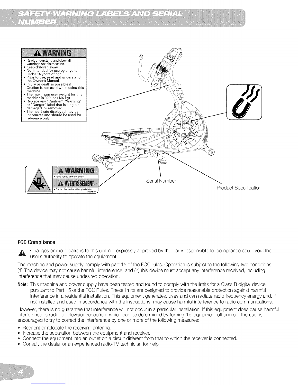
Read, understand and obey all
warnings on this machine.
Keep children away.
Not intended for use by anyone
under 14 years of age.
Prior to use, read and understand
the Owner's Manual.
Injury or death is possible if
Caution is not used while using this
machine.
The maximum user weight for this
machine is 300 Ibs (136 kg).
Replace any "Caution'; "Warning"
or "Danger" label that is illegible,
damaged, or removed.
The heart rate displayed may be
inaccurate and should be used for
reference only.
Keep hands and feet away.
Serial Number
pledslain.
Product Specification
FCCCompliance
,_ Changes or modifications to this unit not expressly approved by the party responsible for compliance could void the
user's authority to operate the equipment.
The machine and power supply comply with part 15 of the FCC rules. Operation is subject to the following two conditions:
(1) This device may not cause harmful interference, and (2)this device must accept any interference received, including
interference that may cause undesired operation.
Note: This machine and power supply have been tested and found to comply with the limits for a Class B digital device,
pursuant to Part 15 of the FCC Rules. These limits are designed to provide reasonable protection against harmful
interference in a residential installation. This equipment generates, uses and can radiate radio frequency energy and, if
not installed and used in accordance with the instructions, may cause harmful interference to radio communications.
However, there is no guarantee that interference will not occur in a particular installation. If this equipment does cause harmful
interference to radio or television reception, which can be determined by turning the equipment off and on, the user is
encouraged to try to correct the interference by one or more of the following measures:
• Reorient or relocate the receiving antenna.
Increase the separation between the equipment and receiver.
Connect the equipment into an outlet on a circuit different from that to which the receiver is connected.
Consult the dealer or an experienced radio/TV technician for help.
Groundinginstructions
This product must be grounded, if itshould malfunction or breakdown, grounding provides a path of least resistance for
electric current to reduce the risk of electric shock. This product isequipped with a cord having an equipment-grounding
conductor and a grounding plug. The plug must be plugged into an appropriate outlet that is properly installed and grounded
in accordance with all local codes and ordinances.
Improper connection of the equipment-grounding conductor can result in a risk of electric shock. Check with
a qualified electrician or serviceman if you are in doubt as to whether the product is properly grounded. Do
not modify the plug provided with the product - if it will not fit the outlet, have a proper outlet installed by a
qualified electrician.
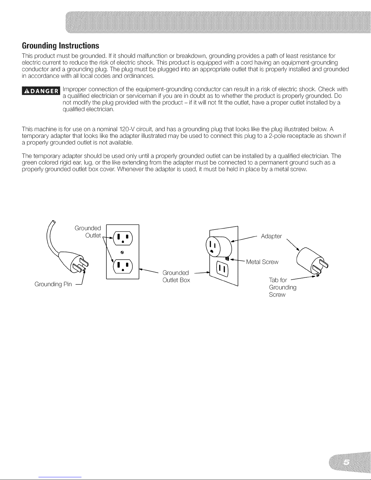
This machine is for use on a nominal 120-V circuit, and has a grounding plug that looks like the plug illustrated below. A
temporary adapter that looks like the adapter illustrated may be used to connect this plug to a 2-pole receptacle as shown if
a properly grounded outlet is not available.
The temporary adapter should be used only until a properly grounded outlet can be installed by a qualified electrician. The
green colored rigid ear, lug, or the like extending from the adapter must be connected to a permanent ground such as a
properly grounded outlet box cover. Whenever the adapter is used, it must be held in place by a metal screw.
Grounding Pin 2
GrOunded
utlet
Grounded
Outlet Box
Adapter
IScrew x,,,_@
Tab for
Grounding
Screw
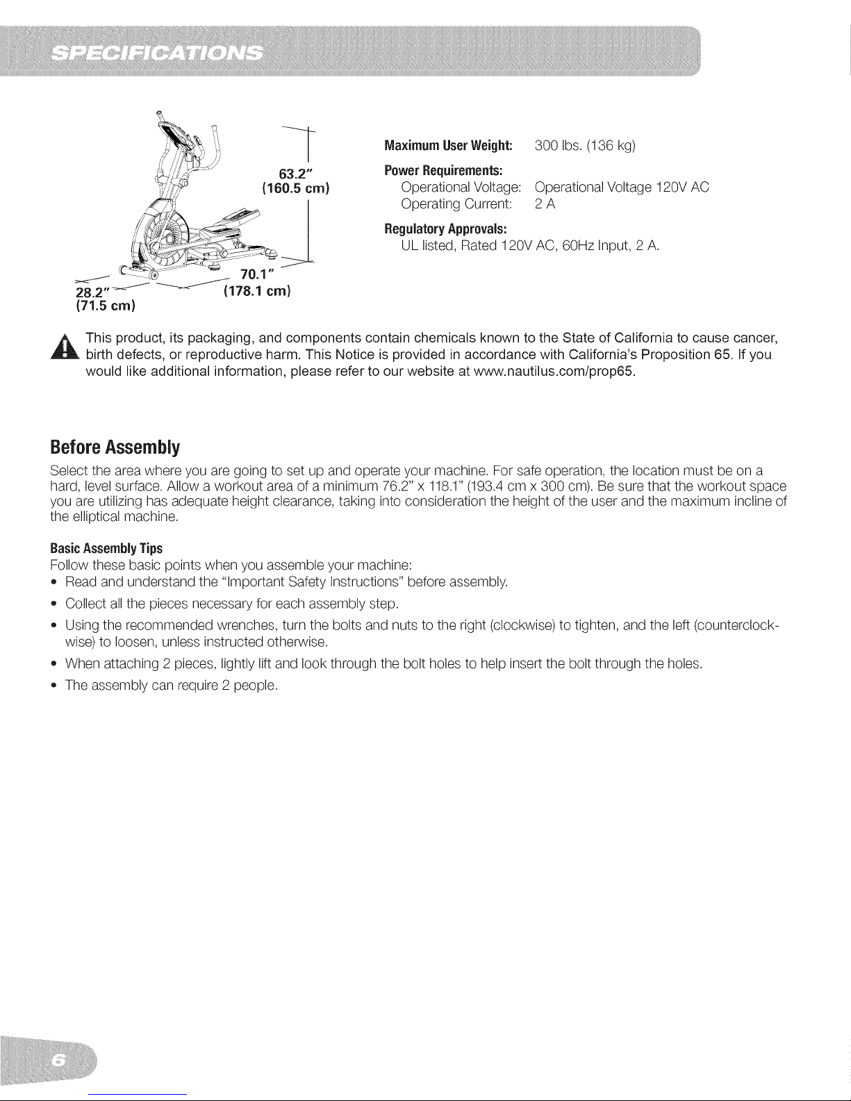
MaximumUserWeight: 300 Ibs. (136 kg)
Power Requirements:
Operational Voltage: Operational Voltage 120V AC
Operating Current: 2 A
RegulatoryApprovals:
UL listed, Rated 120V AC, 60Hz Input, 2 A.
This product, its packaging, and components contain chemicals known to the State of California to cause cancer,
birth defects, or reproductive harm. This Notice is provided in accordance with California's Proposition 65. If you
would like additional information, please refer to our website at www.nautilus.com/prop65.
Before Assembly
Select the area where you are going to set up and operate your machine. For safe operation, the location must be on a
hard, level surface. Allow a workout area of a minimum 76.2" x 118.1" (193.4 cm x 300 cm). Be sure that the workout space
you are utilizing has adequate height clearance, taking into consideration the height of the user and the maximum incline of
the elliptical machine.
BasicAssemblyTips
Follow these basic points when you assemble your machine:
• Read and understand the "Important Safety Instructions" before assembly.
Collect all the pieces necessary for each assembly step.
Using the recommended wrenches, turn the bolts and nuts to the right (clockwise) to tighten, and the left (counterclock-
wise) to loosen, unless instructed otherwise.
When attaching 2 pieces, lightly lift and look through the bolt holes to help insert the bolt through the holes.
The assembly can require 2 people.
21
,y
',,,',\
17
//
/'/
11
13
10
15
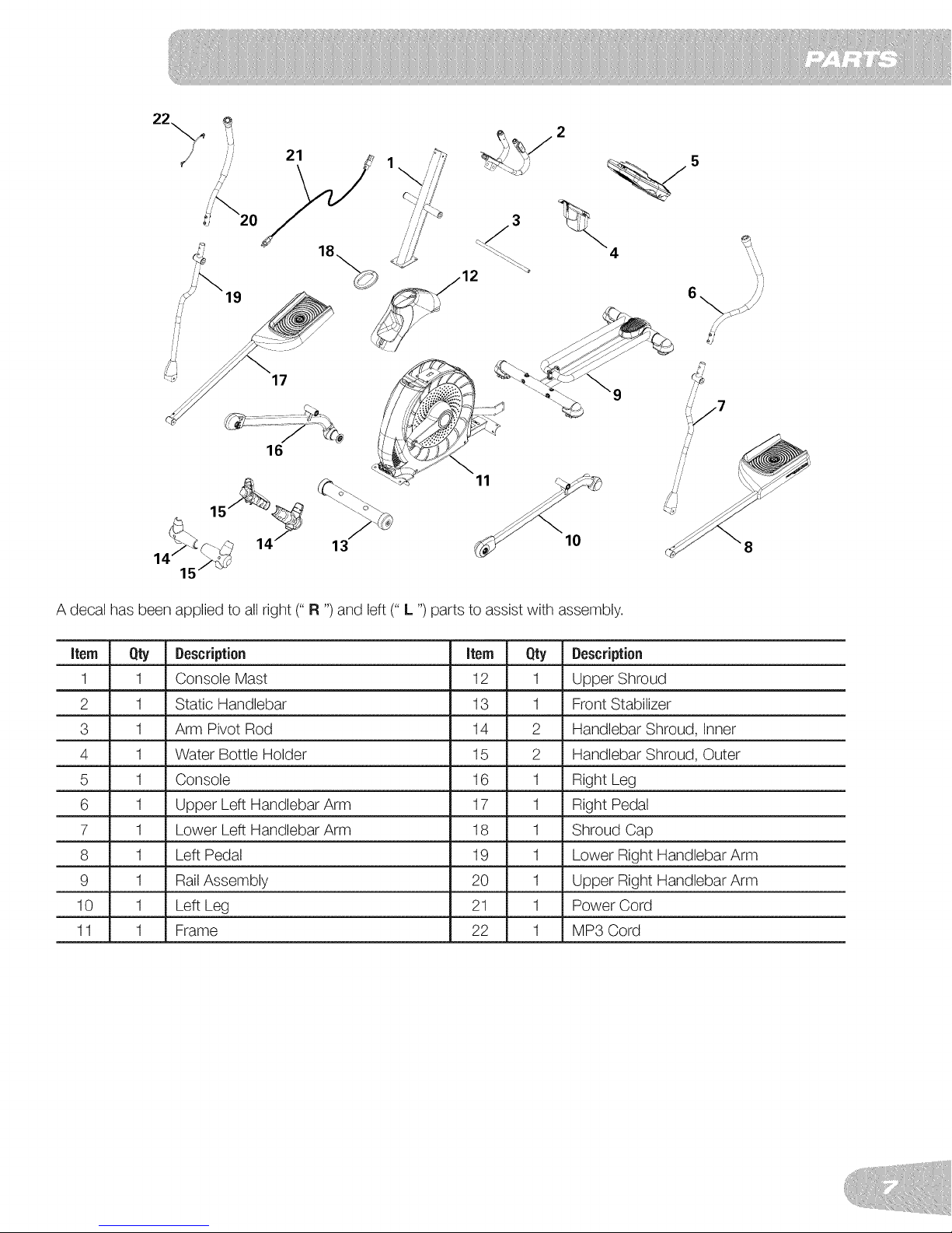
A decal has been applied to all right (" R ")and left (" L ") parts to assist with assembly.
Item Qty Description Item Qty Description
1 1 Console Mast 12 1 Upper Shroud
2 1 Static Handlebar 13 1 Front Stabilizer
3 1 Arm Pivot Rod 14 2 Handlebar Shroud, Inner
4 1 Water Bottle Holder 15 2 Handlebar Shroud, Outer
5 1 Console 16 1 Right Leg
6 1 Upper Left Handlebar Arm 17 1 Right Pedal
7 1 Lower Left Handlebar Arm 18 1 Shroud Cap
8 1 Left Pedal 19 1 Lower Right Handlebar Arm
9 1 Rail Assembly 20 1 Upper Right Handlebar Arm
10 1 Left Leg 21 1 Power Cord
11 1 Frame 22 1 MP3 Cord
B
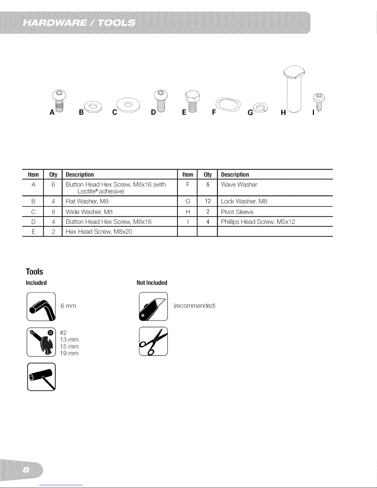
item
Qty Description item Qty Description
A
B 4 Flat Washer, M8 G 12 Lock Washer, M8
C 8 Wide Washer, M8 H 2 Pivot Sleeve
D 4 Button Head Hex Screw, M8x16 I 4 Phillips Head Screw, M5x12
E 2 Hex Head Screw, M8x20
6 Button Head Hex Screw, M8x16 (with F 6 Wave Washer
Loctite®adhesive)
NotIncluded
(recommended)
6mm
#2
13 mm
15 mm
19 mm
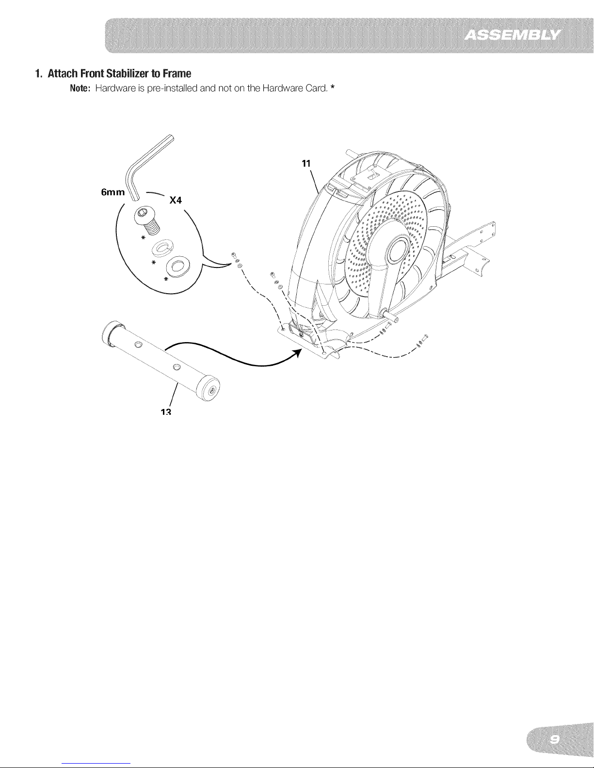
1. AttachFrontStabilizerto Frame
Note: Hardware is pre-installed and not on the Hardware Card. *
11
\
@
\ @
\
\
\
1.'I
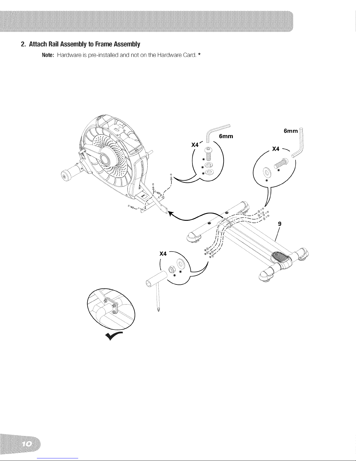
2. AttachRailAssemblyto FrameAssembly
Note: Hardware is pre-installed and not on the Hardware Card. *
X4
li
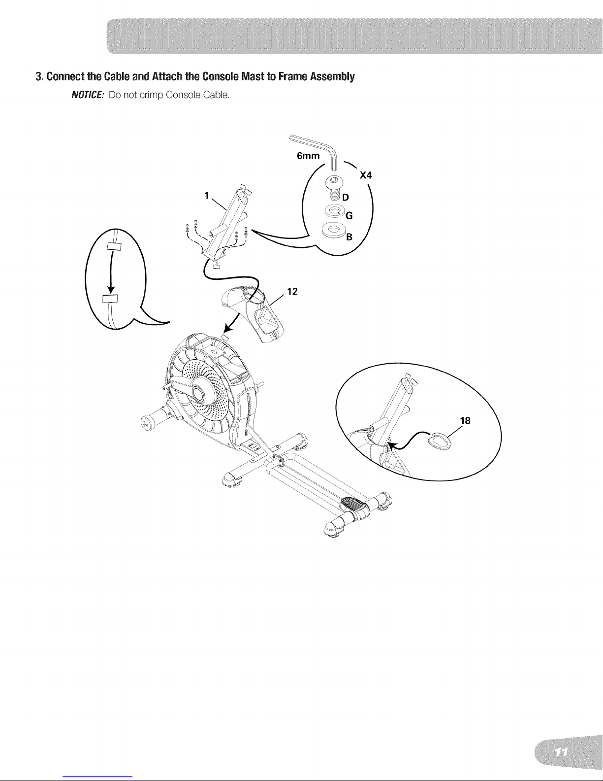
3. Connectthe Cableand Attachthe ConsoleMast to FrameAssembly
NOTICE: Do not crimp Console Cable.
G !
12
X4
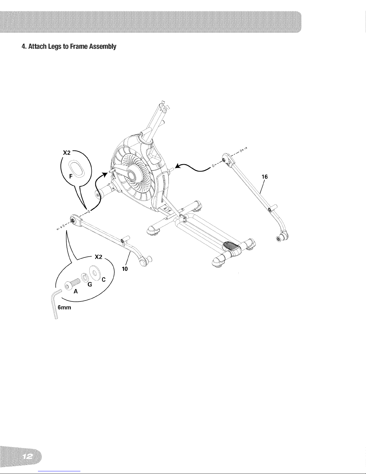
4.AttachLegsto FrameAssembly
10
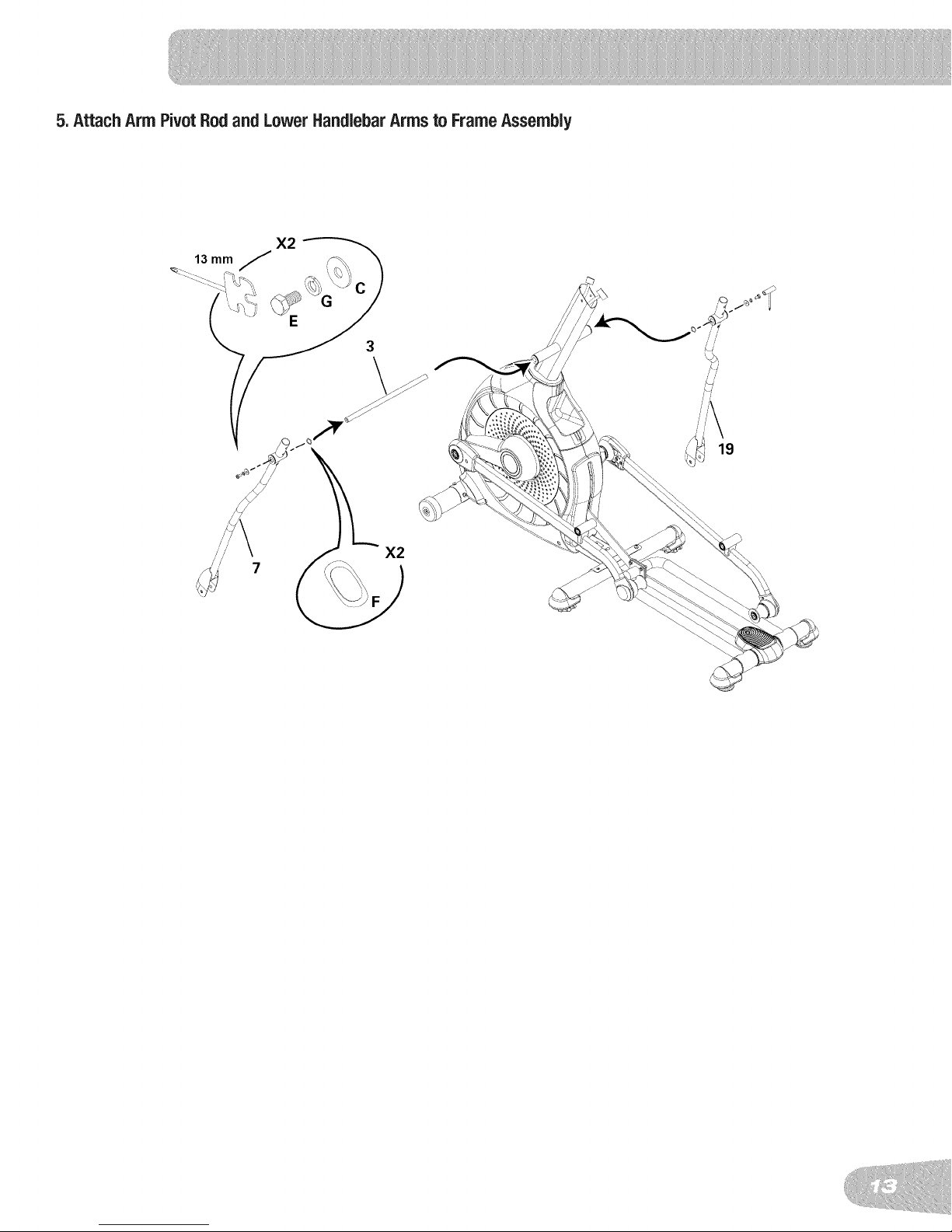
5.AttachArmPivotRodandLower HandlebarArmsto FrameAssembly
19
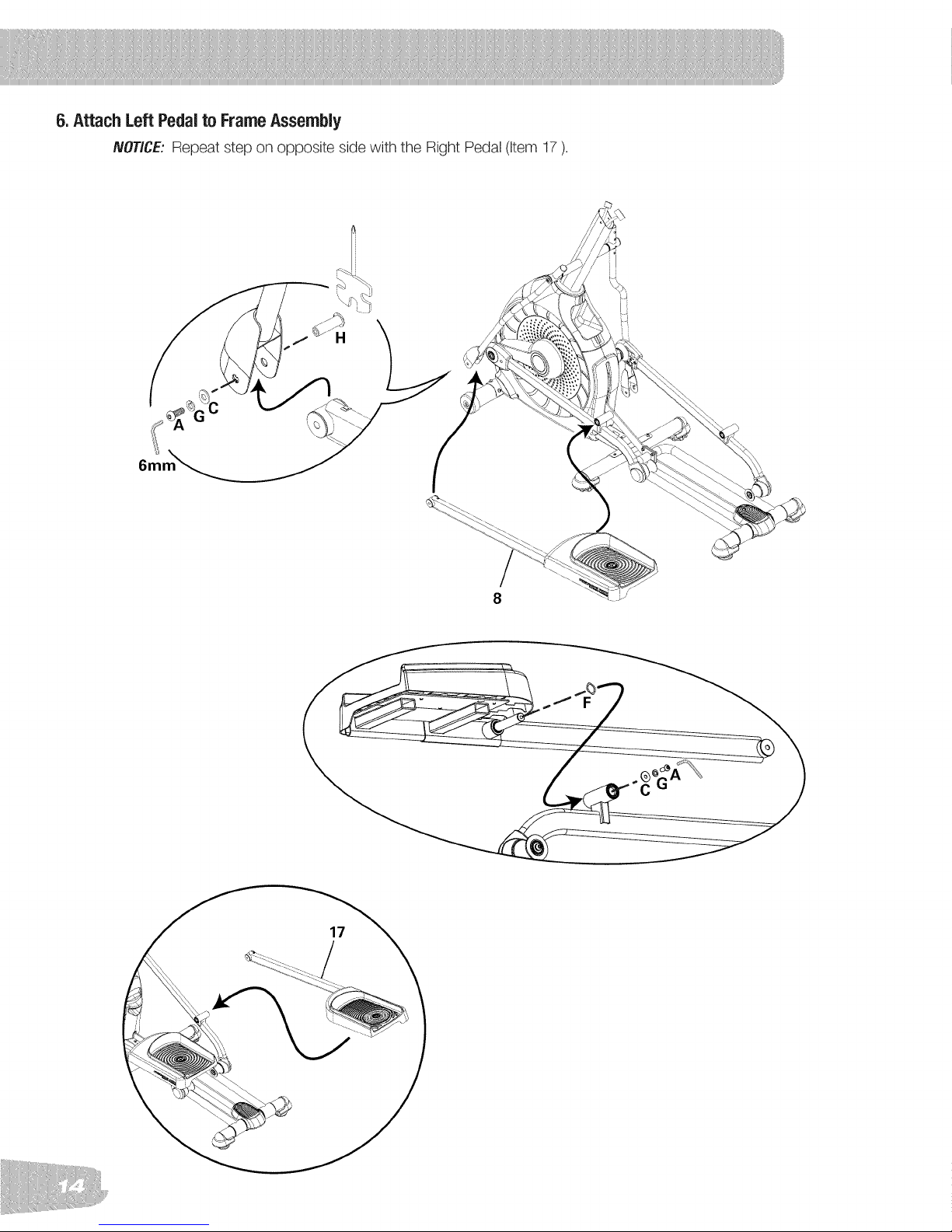
6.AttachLeft Pedalto FrameAssembly
NOTICE: Repeat step on opposite side with the Right Pedal (item 17).
6m
17
)
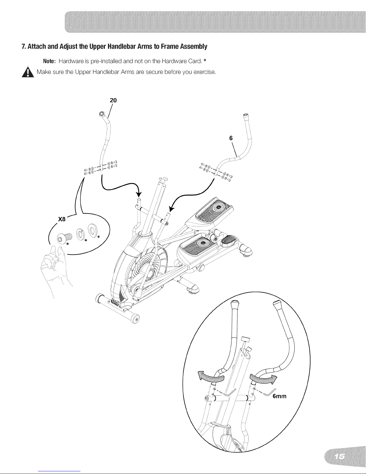
7.AttachandAdjustthe UpperHandlebarArmsto FrameAssembly
Note: Hardware is pro-installed and not on the Hardware Card. *
_Make sure the Upper Handlebar Arms are secure before you exercise.
20
',, ',,
 Loading...