

Page 1
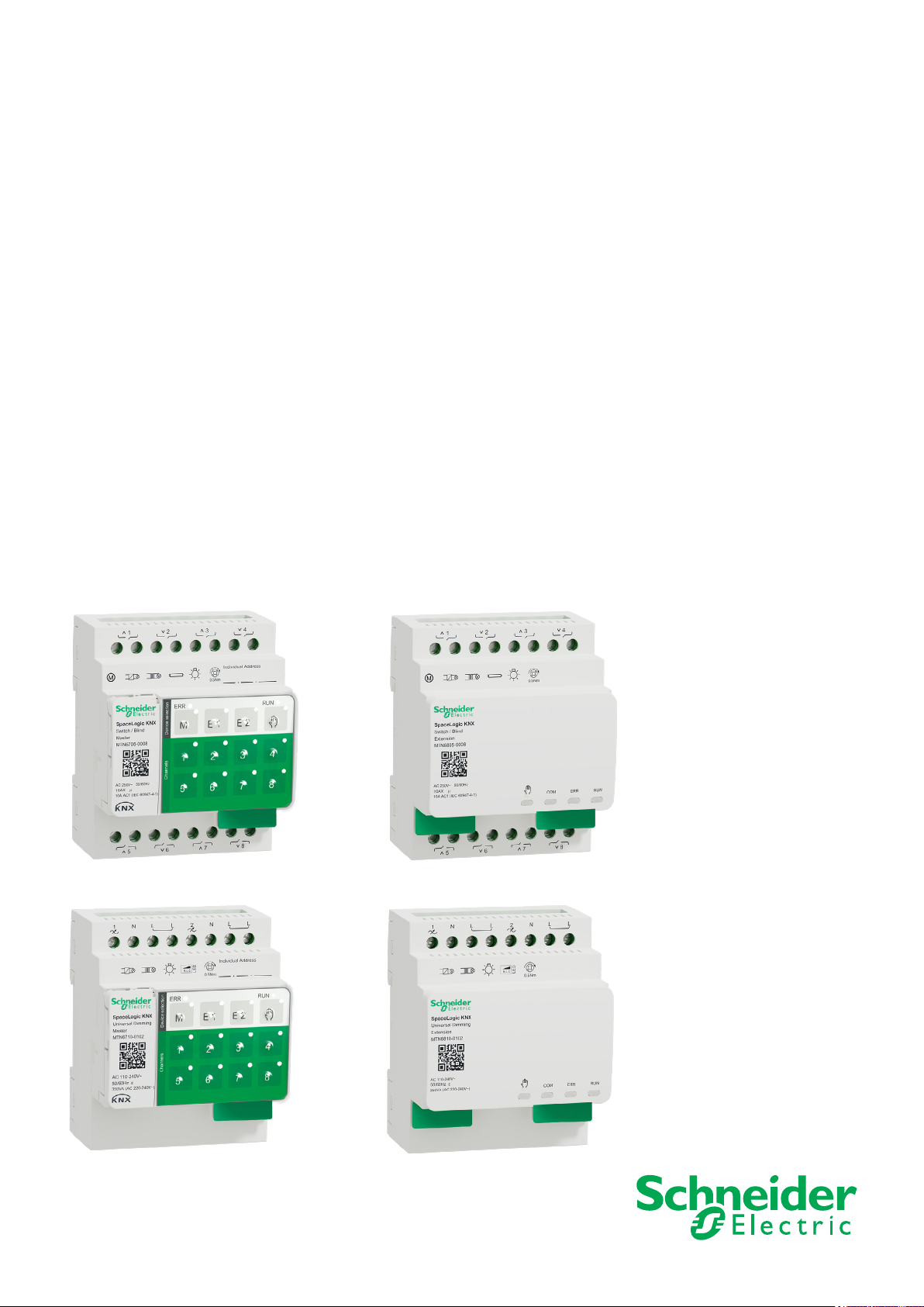
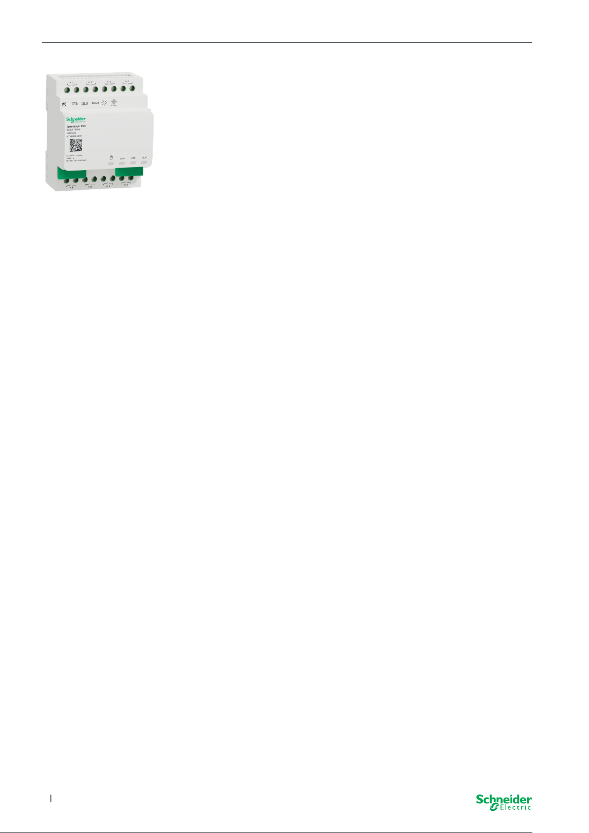
SpaceLogic KNX
Switch/Blind Master
Switch/Blind Extension
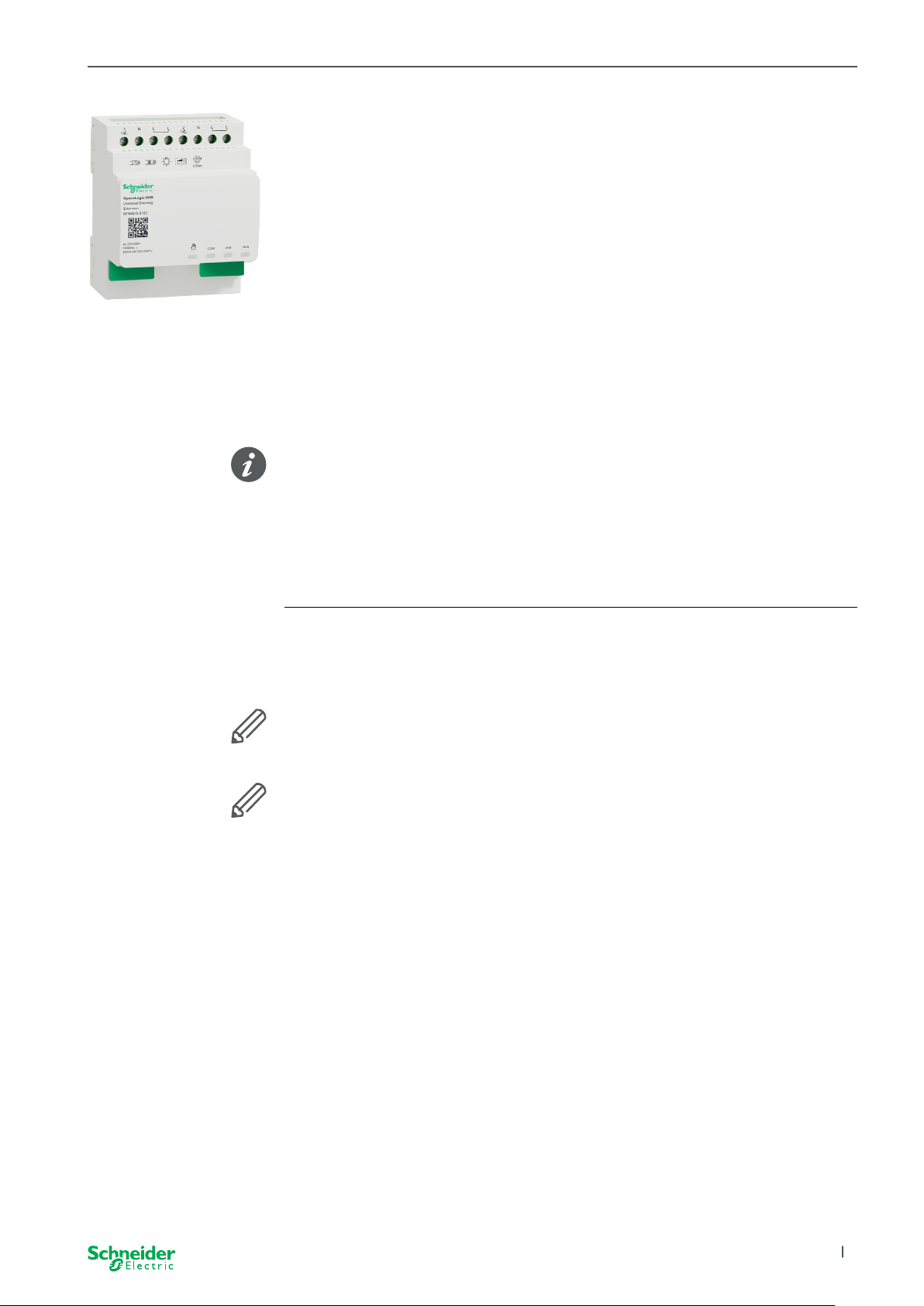
Universal Dimming Master
Universal Dimming Extension
Product Information
This document is based on the installation instructions and gives you further product
information about the SpaceLogic KNX Master and SpaceLogic KNX Extension. This
description contains information about the interaction between master and extension, the commissioning and the behaviour of the LEDs, etc..
MTN6705-0008 | MTN6805-0008 | MTN6710-0102 | MTN6810-0102
2020/09
www.se.com
Page 2

Legal information
The Schneider Electric brand and any trademarks of Schneider Electric SE and its
subsidiaries referred to in this guide are the property of Schneider Electric SE or its
subsidiaries. All other brands may be trademarks of their respective owners.
This guide and its content are protected under applicable copyright laws and furnished for informational use only. No part of this guide may be reproduced or transmitted in any form or by any means (electronic, mechanical, photocopying, recording,
or otherwise), for any purpose, without the prior written permission of Schneider
Electric.
Schneider Electric does not grant any right or license for commercial use of the
guide or its content, except for a non-exclusive and personal license to consult it
on an “as is” basis. Schneider Electric products and equipment should be installed,
operated, serviced, and maintained only by qualied personnel.
As standards, specications, and designs change from time to time, information
contained in this guide may be subject to change without notice.
To the extent permitted by applicable law, no responsibility or liability is assumed by
Schneider Electric and its subsidiaries for any errors or omissions in the informational content of this material or consequences arising out of or resulting from the
use of the information contained herein.
SpaceLogic KNX
MTN6705-0008 | MTN6805-0008 | MTN6710-0102 | MTN6810-0102
2
2020/09
Page 3
SpaceLogic KNX
Warnings
Read these instructions carefully and look at the equipment to become familiar with
the device before trying to install, operate, service, or maintain it. The following
special messages may appear throughout this manual or on the equipment to warn
of potential hazards or to call attention to information that claries or simplies a
procedure.
The addition of either symbol to a “Danger” or “Warning” safety label indicates
that an electrical hazard exists which will result in personal injury if the instructions are not followed.
This is the safety alert symbol. It is used to alert you to potential personal injury
hazards. Obey all safety messages that accompany this symbol to avoid possible
injury or death.
DANGER
DANGER indicates a hazardous situation which, if not avoided, will result
in death or serious injury.
WARNING
WARNING indicates a hazardous situation which, if not avoided, could
result in death or serious injury.
CAUTION
CAUTION indicates a hazardous situation which, if not avoided, could
result in minor or moderate injury
NOTICE
NOTICE is used to address practices not related to physical injury.
Additonal notes
The specied information must be followed, otherwise a program or data error
may occur
Your will nd additional information here to make your work easier.
2020/09 MTN6705-0008 | MTN6805-0008 | MTN6710-0102 | MTN6810-0102
3
Page 4

Table of contents SpaceLogic KNX
ToC
Table of contents
1 Getting to know the Switch/Blind Master ................ 6
1.1 The extended tasks of a Master.................................6
1.2 ETS functions of the Master ...................................7
2 Getting to know the Universal Dimming Master........... 8
2.1 The extended tasks of a Master.................................8
2.2 ETS functions of the Master....................................9
3 Getting to know the Switch/Blind Extension............. 10
4 Getting to know the Universal Dimming Extension ....... 11
5 Connecting Master and Extension..................... 12
5.1 How do I connect master and extensions? .......................12
5.2 Who can be combined with whom ..............................13
5.3 Overview of the devices .....................................13
6 Commissioning of Master and Extension ............... 14
6.1 Perform full commissioning ...................................14
6.2 Perform partial commissioning.................................16
7 Operating and display elements ...................... 18
7.1 Switch/Blind devices ........................................18
Push buttons of the Master ................................18
LEDs of the Master ......................................19
LEDs of the Extension . . . . . . . . . . . . . . . . . . . . . . . . . . . . . . . . . . . . 20
7.2 Universal Dimming devices ...................................21
Push buttons of the Master ................................21
LEDs of the Master ......................................22
LEDs of the Extension . . . . . . . . . . . . . . . . . . . . . . . . . . . . . . . . . . . . 23
7.3 LED behaviour of the Masters .................................24
8 Manual operation: Manual control of channels .......... 25
8.1 Manual operation with low priority ..............................25
8.2 Manual operation with high priority .............................27
9 Reset to factory settings (master reset) ................ 28
10 Execute the firmware update......................... 29
10.1 Master/Extension rmware update..............................29
10.2 Extension rmware update....................................31
10.3 The DFU tool with diagnostics function ..........................31
11 Accessories ....................................... 32
11.1 SpaceLogic KNX Module Link.................................32
11.2 SpaceLogic KNX Cable Link ..................................32
12 Insight into the ETS application ....................... 33
13 FAQs ............................................. 34
4
2020/09MTN6705-0008 | MTN6805-0008 | MTN6710-0102 | MTN6810-0102
Page 5
SpaceLogic KNX
About this document
All information on safe installation and safe connection can only be found in the
installation instructions.
This document gives you further product information about the SpaceLogic KNX
Master and the SpaceLogic KNX Extension. For example, details about the interaction between master and extension, commissioning and the behaviour of the LEDs,
etc.
For your safety
DANGER
HAZARD OF ELECTRIC SHOCK, EXPLOSION, OR ARC FLASH.
Safe electrical installation must be carried out only by skilled professionals. Skilled professionals must prove profound knowledge in the following
areas:
• Connecting to installation networks
• Connecting several electrical devices
• Laying electric cables
• Connecting and establishing KNX networks
• Safety standards, local wiring rules and regulations
Failure to follow these instructions will result in death or serious injury.
The devices and the associated ETS application must not be used to control safety-relevant applications.
2020/09 MTN6705-0008 | MTN6805-0008 | MTN6710-0102 | MTN6810-0102
5
Page 6
Getting to know the Switch/Blind Master SpaceLogic KNX
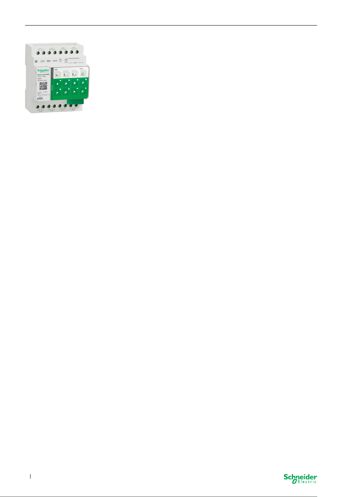
1 Getting to know the Switch/
Blind Master
The SpaceLogic KNX Switch/Blind Master is a KNX actuator that switches a maximum of 8 loads (such as lamps) or controls a maximum of 4 blind motors with end
switches. The assignment of the functions to the channels is freely selectable and
depends on your requirements.
If you need more channels for your project, you can connect so-called SpaceLogic
KNX Switch/Blind Extensions. Just like the master, the channels can be divided into
switch or blind channels. As a master can control a maximum of 2 extensions, a
maximum of 24 loads can be switched or a maximum of 12 blind motors controlled.
All connected loads can be operated manually using the master’s buttons, but this
function can also be deactivated via the ETS. Manual operation: Manual control of
channels --> 25
The status of the device, e.g. status of the channels, operating readiness or activated manual operation, is indicated by several LEDs. More about the behavior can be
found here: Switch/Blind devices --> 18
The Master has control
1.1 The extended tasks of a Master
With a connected Extension, the tasks of the master also become wider. The Master completely controls the extensions, their power supply and also the communication to the bus. You can even program an extension in the existing ETS application
of the Master. And since an Extension has neither a bus coupling nor its own individual address, conventional KNX commissioning is not required for an extension.
Changes in a project, such as the removal, addition or replacement of an extension, can be carried out quickly and easily. Commissioning of Master and Extension
--> 14
All connected loads, including those of the Extensions, can be controlled manually
at the Master, whereby this function can also be deactivated via the ETS. Manual
operation: Manual control of channels --> 25
You can connect a maximum of 2 Extensions to each Master. Which extensions are
available for this purpose can be found here: Who can be combined with whom -->
13.
An example of how the Extension appears in the ETS can be found here: Insight
into the ETS application --> 33
6
2020/09MTN6705-0008 | MTN6805-0008 | MTN6710-0102 | MTN6810-0102
Page 7

Getting to know the Switch/Blind Master SpaceLogic KNX
1.2 ETS functions of the Master
Which functions you can set in the ETS as well as a detailed description of the parameters and values can be found in the ETS application description of the Master.
-> ETS Application Description
ETS functions overview
General and Extended functions
• Central function
• Extension types setting
• Scenes and feedback setting
• Energy saving
• Safety of the equipment
• Health of the equipment
• Manual operation
• PIN code for updating the rmware
Switching actuator functions
• Operation as normally closed/ normally open contact
• Programmable behaviour for the download
• Delay functions for each channel
• Stairwell lighting function with/without manual OFF function
• Switch-o pre-warning for staircase lighting function
• Scenes
• Central function
• Lock function
• Logic operation or priority control
• Status feedback function for each channel
Blind actuator functions
• Duration
• Idle time
• Step Interval
• Lock function
• Limits of the range of motion
• Weather alert
• 8-bit positioning for height and slats
• Scenes
• Status and feedback function
2020/09 MTN6705-0008 | MTN6805-0008 | MTN6710-0102 | MTN6810-0102
7
Page 8

Getting to know the Universal Dimming Master SpaceLogic KNX
2 Getting to know the Univer-
sal Dimming Master
The SpaceLogic KNX Universal Dimming Master is a KNX actuator that switches
and dims a maximum of 2 loads, such as:
• Incandescent and halogen lamps (resistive load)
• LV halogen lamps with dimmable, wound transformers (inductive load)
• LV halogen lamps with dimmable, electronic transformers (capacitive load)
• Combination of resistive and inductive loads
• Combination of resistive and capacitive loads
• Dimmable ESL/CFL
• Dimmable LED lamps
Combinations of inductive and capacitive loads must not be connected to one
output.
Dimmer tool
Schneider Electric has tested numerous dimmable LED and energy saving lamps.
The dimmer tool provides information on dimmable lamps and the minimum and
maximum number of individual lamp models.
When switching on, the actuator automatically detects the connected load. The
following dimming operation modes can be set:
Dimming operation mode Activated by Set up
RC Trailing edge phase Automatic load detection ETS (default) or on the device
RL Leading edge phase Automatic load detection ETS (default) or on the device
RL-LED Leading edge phase * Manual ETS or on the device
*For LEDs/CFLs the RC mode is automatically set. In some cases, however,
LEDs/CFLs may need to be operated in RL-LED mode. Please refer to the instructions of the lamp manufacturers.
Even during operation, the load is checked for inductive behaviour and, if
necessary, switched to RL mode. Please note that a load may only be exchanged
when the mains voltage is switched o.
To increase the number of channels, you can connect a maximum of 2 extensions
to the master. Depending on the required function, the SpaceLogic KNX Universal
Dimmer Extension and the SpaceLogic KNX Switch/Blind Extension can be used.
All connected loads can be operated manually using the master’s buttons, but this
function can also be deactivated via the ETS. Manual operation: Manual control of
channels --> 25
The status of the device, e.g. status of the channels, operating readiness or activated manual operation, is indicated by several LEDs. More about the behavior can be
found here: Universal Dimming devices --> 21
2.1 The extended tasks of a Master
The Master has control
8
With a connected Extension, the tasks of the master also become wider. The Master completely controls the extensions, their power supply and also the communication to the bus. You can even program an extension in the existing ETS application
of the Master. And since an Extension has neither a bus coupling nor its own individual address, conventional KNX commissioning is not required for an extension.
2020/09MTN6705-0008 | MTN6805-0008 | MTN6710-0102 | MTN6810-0102
Page 9

Getting to know the Universal Dimming Master SpaceLogic KNX
Changes in a project, such as the removal, addition or replacement of an extension, can be carried out quickly and easily. Commissioning of Master and Extension
--> 14
All connected loads, including those of the Extensions, can be controlled manually
at the Master, whereby this function can also be deactivated via the ETS. Manual
operation: Manual control of channels --> 25
You can connect a maximum of 2 Extensions to each Master. Which extensions are
available for this purpose can be found here: Who can be combined with whom -->
13.
An example of how the Extension appears in the ETS can be found here: Insight
into the ETS application --> 33
2.2 ETS functions of the Master
Which functions you can set in the ETS as well as a detailed description of the parameters and values can be found in the ETS application description of the Master.
-> ETS Application Description
ETS functions overview
General and extended functions
• Central function
• Extension types setting
• Scenes and feedback setting
• Energy saving
• Safety of the equipment
• Health of the equipment
• Manual operation
• PIN code for updating the rmware
Dimming functions
• Basic functions: Switching (1 bit), relative dimming (4 bit), absolute dimming/
value dimming (1 byte)
• Switch-on behaviour (via switch object)
• Execution of the selected switch-on behaviour
• Behaviour of switch object
• Dimming curve
• Minimum/maximum brightness
• Always start at 50% brightness (ESL/CFL)
• Dimming operation mode
• Dimming object/value object switches channel
• Scenes
• Status feedback, switching/value
• Dimming times: Times for switching, dimming, values, priority, scenes
• Time setting: Staircase time, On/O delay time
• Priority function, Locking function
• Safety and alarm settings: Safety function, alarm function, failure and download
behaviour
Switching/Blind actuator functions
To ensure the operation of a switch/blind extension, all functions of the switch/blind
master are available. ETS functions of the Master --> 7
2020/09 MTN6705-0008 | MTN6805-0008 | MTN6710-0102 | MTN6810-0102
9
Page 10
Getting to know the Switch/Blind Extension SpaceLogic KNX
3 Getting to know the Switch/
Blind Extension
The SpaceLogic KNX Switch/Blind Extension is an actuator that extends the channels of a SpaceLogic KNX Switch/Blind Master and the channels of a SpaceLogic
KNX Universal Dimming Master. The extension can switch a maximum of 8 loads
(such as lamps) or control a maximum of 4 blind motors with end switches. The
distribution of the functions to the channels is freely selectable and depends on
your requirements.
All connected loads can be operated manually using the master’s buttons, but this
function can also be deactivated via the ETS. Manual operation: Manual control of
channels --> 25
The status of the device, e.g. status of the channels, operating readiness or activated manual operation, is indicated by several LEDs of the master device. More
about the behavior can be found here. Switch/Blind devices --> 18
The Master takes over the control
The Master completely controls the extensions, their power supply and also the
communication to the bus. You can even program an extension in the existing ETS
application of the master. And since an extension has neither a bus coupling nor
its own individual address, conventional KNX commissioning is not required for an
extension.
Changes in a project, such as the removal, addition or replacement of an extension, can be carried out quickly and easily. Commissioning of Master and Extension
--> 14
An example of how the Extension appears in the ETS can be found here: Insight
into the ETS application --> 33
10
2020/09MTN6705-0008 | MTN6805-0008 | MTN6710-0102 | MTN6810-0102
Page 11
Getting to know the Universal Dimming Extension SpaceLogic KNX
4 Getting to know the Univer-
sal Dimming Extension
The SpaceLogic KNX Universal Dimming Extension is an actuator that extends
the channels of a SpaceLogic KNX Universal Dimming Master. The extension can
switch and dim a maximum of 2 loads, such as:
• Incandescent and halogen lamps (resistive load)
• LV halogen lamps with dimmable, wound transformers (inductive load)
• LV halogen lamps with dimmable, electronic transformers (capacitive load)
• Combination of resistive and inductive loads
• Combination of resistive and capacitive loads
• Dimmable ESL/CFL
• Dimmable LED lamps
Combinations of inductive and capacitive loads must not be connected to one
output.
Dimmer tool
Schneider Electric has tested numerous dimmable LED and energy saving lamps.
The dimmer tool provides information on dimmable lamps and the minimum and
maximum number of individual lamp models.
When switching on, the actuator automatically detects the connected load. The
following dimming operation modes can be set:
Dimming operation mode Activated by Set up
RC Trailing edge phase Automatic load detection ETS (default) or on the device
RL Leading edge phase Automatic load detection ETS (default) or on the device
RL-LED Leading edge phase * Manual ETS or on the device
*For LEDs/CFLs the RC mode is automatically set. In some cases, however,
LEDs/CFLs may need to be operated in RL-LED mode. Please refer to the instructions of the lamp manufacturers.
Even during operation, the load is checked for inductive behaviour and, if
necessary, switched to RL mode. Please note that a load may only be exchanged
when the mains voltage is switched o.
All connected loads can be operated manually using the master’s buttons, but this
function can also be deactivated via the ETS. Manual operation: Manual control of
channels --> 25
The status of the device, e.g. status of the channels, operating readiness or activated manual operation, is indicated by several LEDs of the master device. More
about the behavior can be found here. Universal Dimming devices --> 21
The Master takes over the control
The Master completely controls the extensions, their power supply and also the
communication to the bus. You can even program an extension in the existing ETS
application of the master. And since an extension has neither a bus coupling nor
its own individual address, conventional KNX commissioning is not required for an
extension.
Changes in a project, such as the removal, addition or replacement of an extension, can be carried out quickly and easily. Commissioning of Master and Extension
--> 14
An example of how the Extension appears in the ETS can be found here: Insight
into the ETS application --> 33
2020/09 MTN6705-0008 | MTN6805-0008 | MTN6710-0102 | MTN6810-0102
11
Page 12

Connecting Master and Extension SpaceLogic KNX
ME
5 Connecting Master and Ex-
tension
5.1 How do I connect master and extensions?
Master and extensions are connected to each other via the so-called link interface.
The link interface is used for communication between the devices and to supply
power to the extensions. There are three dierent connection options, which you
use depending on the distance between the devices in the cabinet
Comercial reference Maximum distance
SpaceLogic KNX
Module Link
SpaceLogic KNX
Cable Link S
MTN6940-0000 (supplied with the
extension)
MTN6941-0001 30 cm
-
What kind of connection do I
use in which situation?
SpaceLogic KNX
Cable Link L
Remove link interface cap
1
2 Plug in the SpaceLogic KNX Module Link or
MTN6941-0002 150 cm
Cable Link
Use cases
If the devices are placed alongside
each other, use the SpaceLogic KNX
Module Link.
ME1E2
If the devices are placed at a distance
from each other, use the SpaceLogic
KNX Cable Link.
1
12
M = Master
E1/E2 = Extension 1 / Extension 2
O = Output
I = Input
E2
Pay attention to the plugging from output to input. If the connecting Cable Link is
accidentally plugged in incorrectly, you cannot put the devices into operation. In
this case, the corresponding extension LED (E1 or E2) on the master ashes.
2020/09MTN6705-0008 | MTN6805-0008 | MTN6710-0102 | MTN6810-0102
Page 13

Connecting Master and Extension SpaceLogic KNX
Example in a cabinet
5.2 Who can be combined with whom
You can connect a maximum of 2 extensions to one master. The following table
shows who can be combined with whom.
SpaceLogic KNX
Switch/Blind Master x
Universal Dimming Master x x
Switch/Blind
Extension
Universal Dimming
Extension
5.3 Overview of the devices
Depending on the functions, you can use dierent devices:
SpaceLogic KNX Article no. Functions
Switch/Blind Master MTN6705-0008 8 switching channels and/or 4 blinds/roller shut-
Switch/Blind Extension MTN6805-0008 8 switching channels and/or 4 blinds/roller shut-
Universal Dimming Master MTN6710-0102 2 dimming channels
Universal Dimming Extension MTN6810-0102 2 dimming channels
ters · the combination is freely selectable
ters · the combination is freely selectable
2020/09 MTN6705-0008 | MTN6805-0008 | MTN6710-0102 | MTN6810-0102
13
Page 14

Commissioning of Master and Extension SpaceLogic KNX
6 Commissioning of Master
and Extension
The KNX commissioning of a master is similar to any other KNX device. It does
not matter whether you just want to commission a master or also the extensions
connected to it. When the master is commissioned, the connected extensions are
also commissioned automatically.
If the extensions are connected but not parameterised in the ETS, the correspon-
ding extension LED (E1 or E2) on the master ashes.
There are 2 commissioning procedures that you carry out depending on the case:
• Full commissioning
• Partial commissioning
You carry out full commissioning when you
• load the ETS application/individual address into the master
• replace a master
• permanently remove or add an extension
• replace an extension with another extension type (dimmer/switch)
• want to change the order of the extensions
Perform full commissioning --> 14
the partial commissioning is carried out when you:
• replace an extension with the same extension type
Perform partial commissioning --> 16
6.1 Perform full commissioning
You carry out full commissioning when you:
• load the ETS application and physical address into the master for the rst time
• replace a master
• permanently remove or add an extension
• replace an extension with another extension type (dimmer/switch)
• want to change the order of the extensions
During full commissioning, the master receives the ETS application (and the indi-
vidual address, if applicable) and conguration data is loaded into the connected
extensions.
During the process, the order of the extensions is always congured: the extension
connected to the master is assigned the address “1”, the following extension is
assigned the address “2”.
14
2020/09MTN6705-0008 | MTN6805-0008 | MTN6710-0102 | MTN6810-0102
Page 15

Commissioning of Master and Extension SpaceLogic KNX
ME
NOTICE
Check before commissioning: The load connections and the order of the
devices (Master -> Extension 1 -> Extension 2) must correspond to your
ETS programming
• Connect blind motors to the blind channels
specied in the ETS.
• Connect loads to the switching channels
(or dimming channels) specied in the
ETS.
• If the extension is planned as extension 1
(E1), connect it directly to the master.
• If the extension is planned as extension 2
(E2), then connect it to extension 1.
An extension cannot be put into operation if the order of the devices does
not correspond to your ETS conguration.
After you have completed the ETS programming:
1 Connect your PC/notebook to the KNX bus.
B
1
E2
C
RUNERRCOM
ERR RUN
M E 1 E 2
1 2 3 4
A
2 Press programming button A
On the Master On the Extension
⇒ The programming LED A lights up. -
3
Load ETS application and individual address into the device.
On the Master On the Extension
⇒ The programming LED A goes out.
⇒ The RUN LED B lights up.
5 6 7 8
⇒ The RUN LED C lights up
During the following initialization phase of 12 s maximum, the device is out of
function.
2020/09 MTN6705-0008 | MTN6805-0008 | MTN6710-0102 | MTN6810-0102
15
Page 16

Commissioning of Master and Extension SpaceLogic KNX
ME
6.2 Perform partial commissioning
The partial commissioning is carried out when you:
• replace an extension with the same extension type
During partial commissioning, conguration data is only loaded into the new extensions. An existing extension only receives conguration data if the data is inconsis-
tent
In addition:
• The rmware version is checked.
• The order of the extensions is checked.
The partial commissioning is done during normal operation
NOTICE
Check before commissioning: The load connections and the order of the
devices (Master -> Extension 1 -> Extension 2) must correspond to your
ETS programming.
• Connect blind motors to the blind channels
specied in the ETS.
1
• Connect loads to the switching channels
(or dimming channels) specied in the
ETS.
• If the extension is planned as extension 1
(E1), connect it directly to the master.
E2
• If the extension is planned as extension 2
(E2), then connect it to extension 1.
An extension cannot be put into operation if the order of the devices does
not correspond to your programming in the ETS.
16
2020/09MTN6705-0008 | MTN6805-0008 | MTN6710-0102 | MTN6810-0102
Page 17

Commissioning of Master and Extension SpaceLogic KNX
After you have replaced the extension:
1 Press and hold master push button A for 7 seconds.
On the Master On the Extension
⇒ The Master LED A goes out after 7 seconds
⇒ The RUN LED B ashes ⇒ The COM-LED D goes out
C
A
E
B
RUNERRCOM
D
ERR RUN
M E 1 E 2
1 2 3 4
5 6 7 8
The conguration data is loaded.
On the Master On the Extension
⇒ The COM LED D ashes
During the following initialization phase of 12 s maximum, the device is out of func-
tion. The conguration data have been successfully loaded when all RUN LEDs are
switched on again.
If the new extension has a non-compatible rmware version, the extension LED
(E) ashes and you must perform a rmware update. Extension rmware update
--> 31
2020/09 MTN6705-0008 | MTN6805-0008 | MTN6710-0102 | MTN6810-0102
17
Page 18

Operating and display elements SpaceLogic KNX
18
RR
34
78
7 Operating and display ele-
ments
7.1 Switch/Blind devices
Push buttons of the Master
Service
ER
ME1E2
KNX
12
Channels Device selection
56
M
Master push button
Short press: Selection of the master. The status LEDs indicate the current
UN
Long press: Partial commissioning --> 16
Extension 1 push button
status of the master.
E1
Short press: Selection of the extension 1. The status LEDs indicate the cur-
Long press: Firmware Update after Replacing an Extension --> 31
Extension 2 push button
rent state of extension 1.
E2
Short press: Selection of the extension 2. The status LEDs indicate the cur-
Long press: Firmware Update after Replacing an Extension --> 31
Manual push button
Switching to manual operation
Short press: Manual operation with low priority --> 25
Long press: Manual operation with high priority --> 27
...
Channel push button
As soon as the manual operation is activated, you can control the channels activated in the ETS.
ETS application
loaded:
rent state of extension 2.
Switch and control channels.
18
ETS application
not loaded:
KNX programming button with integrated LED
KNX
Service
Short press KNX commissioning --> 14
Press and hold Triggers the master reset --> 28
Service Port
Firmware update and diagnostics --> 29
Manual operation with low priority: 2 channels can be controlled
at a time: push button 1/2 or 3/4 or 5/6 or 7/8
For wiring test purposes.
Manual operation with high priority (long press): all channels can
be controlled.
2020/09MTN6705-0008 | MTN6805-0008 | MTN6710-0102 | MTN6810-0102
Page 19

Operating and display elements SpaceLogic KNX
RUN
ERR
M
E1
E2
1
RR
34
78
LEDs of the Master
RUN LED
Shows the current operating status of the device.
Service
ER
ME1E2
KNX
12
Channels Device selection
56
UN
On ETS application loaded, device in operation
Flashes slowly Firmware update of the master
Flashes fast Extension commissioning (full/partial commissioning, initial testing)
O ETS application not active. Only wiring test possible
Error LED
Displays an internal error, e.g. relay powered not sucient due to missing power supply.
For error details, please refer to the diagnostic tool.
On Internal error master (power supply, device error, ...) or error master
during the rmware update
Flashes External error master
Master / Extension 1 / Extension 2 LED
Indicates that either Master, Extension 1, or Extension 2 has been selected.
M, E1 or E2
On
The device was selected. You can identify the channel states of the
device by means of the status LEDs.
E1 ashes Error Extension 1
E2 ashes Error Extension 2
M, E1 or E2
The extensions receive the rmware update from the master
On
Manual LED
Indicates that the unit has been switched to manual operation.
On Manual operation with low priority active
Flashes Manual operation with high priority active
Status LED
8
...
Shows the physically current status of the channels (independent of the ETS conguration)
On Relay contact closed
O Relay contact opened
KNX programming button with integrated LED
KNX
Shows the status during KNX commissioning. Device is in programming mode.
Flashes KNX commissioning
2020/09 MTN6705-0008 | MTN6805-0008 | MTN6710-0102 | MTN6810-0102
19
Page 20

LEDs of the Extension
RUN
ERR
COM
RUN LED
Shows the current operating status of the device.
Operating and display elements SpaceLogic KNX
O Wiring test or device does not work (rmware version or extension type not
On ETS application loaded, device in operation
RUNERRCOM
Flashes slowly Firmware update of the master
Flashes fast Extension commissioning (full/partial commissioning, initial testing)
The RUN LED ashes during commissioning.
Error LED:
On Internal error extension (e.g. self test). For error details, please refer to the
Flashes External error extension
COM LED
Flashes Indicates that the master and the extension are communicating.
On Firmware update
Manual LED
On Indicates that manual operation has been activated for the device. The
compatible). In this case, the corresponding extension LED E1/E2 ashes
on the master.
diagnostic tool.
channels of the extension can now be controlled using the channel push
buttons of the master.
This function can also be used to identify the extension in the cabinet. -->
35
20
2020/09MTN6705-0008 | MTN6805-0008 | MTN6710-0102 | MTN6810-0102
Page 21

Operating and display elements SpaceLogic KNX
13
24
57
68
56
78
RR
34
78
34
78
7.2 Universal Dimming devices
Push buttons of the Master
Service
ER
ME1E2
KNX
UN
12
Channels Device selection
56
12
56
RL<> RC RL-LED RL<> RC RL-LED
M
E1
E2
1234
Master push button
Short press: Selection of the master. The status LEDs indicate the current
Long press: Partial commissioning --> 16
Extension 1 push button
Short press: Selection of the extension 1. The status LEDs indicate the
Long press: Firmware Update after Replacing an Extension --> 31
Extension 2 push button
Short press: Selection of the extension 2. The status LEDs indicate the
Long press: Firmware Update after Replacing an Extension --> 31
Manual push button
Switching to manual operation
Short press: Manual operation with low priority --> 25
Long press: Manual operation with high priority --> 27
Channel push buttons
As soon as the manual operation is activated, you can control the channels activated in the ETS.
ETS application
loaded:
ETS application not
loaded:
status of the master.
current state of extension 1.
current state of extension 2.
Switch and dim channels.
Both channels can be controlled at the same time. The
dimming function is deactivated, only On/O switching is
possible.
For wiring test purposes.
5678
RL<> RC RL-LED RL<> RC RL-LED
KNX
Service
Short/long press: Lamp is switched on/dimmed brighter
Short/long press: Lamp is switched o/dimmed darker
Function buttons
As soon as the manaul operation is activated, you can set the dimming operation
modes for example.
Short press
Short press: Channel 1/2: RL-LED Operating mode is activated
Long press on both
buttons:
Long press on both
buttons:
KNX programming button with integrated LED
Short press KNX commissioning --> 14
Press and hold Triggers the master reset --> 28
Service Port
Firmware update and diagnostics --> 29
Channel 1/2: Automatic load detection is activated (LED
lights up)
Channel 1: Counter reset
The dimmer can collect the following information: number of
switching operations and number of light hours.
Channel 2: Counter reset
The dimmer can collect the following information: number of
switching operations and number of light hours
2020/09 MTN6705-0008 | MTN6805-0008 | MTN6710-0102 | MTN6810-0102
21
Page 22

LEDs of the Master
RUN
ERR
M
E1
E2
1
3
2
4
5
7
6
8
5
7
8
RR
34
78
34
78
RUN-LED
Shows the current operating status of the device.
Operating and display elements SpaceLogic KNX
Service
ER
ME1E2
KNX
12
Channels Device selection
56
UN
On ETS application loaded, device in operation
Flashes slowly Firmware update of the master
Flashes fast Extension commissioning (full/partial commissioning, initial
testing)
O ETS application not active. Only wiring test possible
Error LED
Shows an internal/external error.
On Internal Error (e.g. device is only powered during rmware update
by USB)
Flashes External error (e.g. shortcut, frequency out of range, overload,
loose wire, load is not detected)
Master / Extension 1 / Extension 2 LED
Indicates that either Master, Extension 1, or Extension 2 has been selected.
M, E1 or E2 On The device was selected. You can identify the channel states of
the device by means of the status LEDs.
E1 ashes Error Extension 1 (e.g.: the ETS conguration does not corre-
spond to the installation or a dierent extension type is used.)
E2 ashes Error Extension 2 (e.g.: the ETS conguration does not corre-
spond to the installation or a dierent extension type is used.)
M, E1 or E2 On The extensions receive the rmware update from the master
Manual LED
Indicates that the unit has been switched to manual operation.
On Manual operation with low priority active
Flashes Manual operation with high priority active
12
56
RL<> RC RL-LED RL<> RC RL-LED
Status-LED of channels
Shows the physically current status of channel 1 and 2 (C1/C2).
On Channel is On (1 % - 100 %)
O Channel is O
O Channel 1/2 is powered
Flashes fast
Flashes slow
On Channel 1/2 is oine
Status-LED of functions
Shows the status of the dimming operation modes of channel 1 and 2 (C1/C2)
On Automatic load detection is active (RL or RC mode is active)
O Automatic load detection is not active
On RL-LED mode is active
O RL-LED mode is not active
Flashes Channel 1: Counter reset is ongoing
6
External error of channel 1/2 (e.g. shortcut, frequency out of
range) Mains voltage reset is needed
External error of channel 1/2 (e.g. overload, loose wire, no load)
The application or the user has to stop it.
22
Flashes Channel 2: Counter reset is ongoing
2020/09MTN6705-0008 | MTN6805-0008 | MTN6710-0102 | MTN6810-0102
Page 23

Operating and display elements SpaceLogic KNX
RUN
ERR
COM
KNX programming button with integrated LED
KNX
Shows the status during KNX commissioning. Device is in programming mode.
Flashes KNX commissioning
LEDs of the Extension
RUN LED
Shows the current operating status of the device.
O Wiring test or device does not work (rmware version or extension type not
On ETS application loaded, device in operation
RUNERRCOM
Flashes slowly Firmware update of the master
Flashes fast Extension commissioning (full/partial commissioning, initial testing)
The RUN LED ashes during commissioning.
Error LED
On Internal error extension (e.g. self test). For error details, please refer to the
Flashes External error extension (overload, no load, ... )
COM LED
Flashes Indicates that the master and the extension are communicating.
On Firmware update
Manual LED
On Indicates that manual operation has been activated for the device. The
compatible). In this case, the corresponding extension LED E1/E2 ashes
on the master.
diagnostic tool.
channels of the extension can now be controlled using the channel push
buttons of the master.
This function can also be used to identify the extension in the cabinet. -->
35
2020/09 MTN6705-0008 | MTN6805-0008 | MTN6710-0102 | MTN6810-0102
23
Page 24

Operating and display elements SpaceLogic KNX
RUN
M
E1
E2
ERR
RUN
M
E1
E2
ERR
RUN
M
E1
E2
ERR
RUN
M
E1
E2
ERR
7.3 LED behaviour of the Masters
Commissioning
Wiring test - - On - - - - released
Commissioning,
switching on the voltage
KNX commissioning Flashes - - - - - - locked
Normal operation
Device ready for operation On - - - - - released
ETS application not active - - - - - - released
Manual operation with low priority active On On On - - - released
Manual operation with high priority active On Flashes On - - - released
Master selected On - On - - - released
Extension 1 selected On - - On - - released
Extension 2 selected On - - - On - released
Internal error - - - - - On released
External error Master On - - (On) (On) Flashes released
Error Extension On - - Flashes Flashes - released
Error of Master/Extension/Extension conguration** On - - (On) (On) - released
Device Firmware Update
Firmware update of the master Flashes - - - - - locked
Firmware update of the master* Flashes - - - - On locked
Firmware update of the extensions - - On On On - locked
Firmware update of the extensions* - - On On On On locked
KNX
-
On
for 1 s
On
for 1 s
On
for 1 s
On
for 1 s
On
for 1 s
On
for 1 s
Push-button
function
locked
Push-button
function
Push-button
function
Error indication
Internal error - - - - - On released
External error master (concern extensions)** On - - (On) (On) Flashes released
Error extension 1 (e.g. O/l swapped by CableLink) On - - Flashes - - released
Error extension 2 (e.g. O/l swapped by CableLink) On - - - Flashes - released
* The rmware update is stopped and the device is put into error mode. The partial commissioning or the rmware update can be initiated via the keypad.
If the KNX bus is not connected and the device is only powered via micro USB, all Error LEDs will light up (master and extensions). If power is supplied via the KNX bus, all Error LEDs
are o.
** LEDs E1/E2 indicate incompatible rmware or a connected extension that does not match the ETS programming.
Push-button
function
24
2020/09MTN6705-0008 | MTN6805-0008 | MTN6710-0102 | MTN6810-0102
Page 25

Manual operation: Manual control of channels SpaceLogic KNX
RR
8 Manual operation: Manual
control of channels
With the manual operation you can control the channels directly from the master
device. This function is used if, for example, you want to set a certain constellation
for maintenance/cleaning work or for testing.
There are two dierent types of manual operation:
• Manual operation with low priority --> 25
Select this manual operation if you want to test a channel or check its status.
• Manual operation with high priority --> 27
You select this manual operation if maintenance or cleaning work is to be carried out on the loads.
8.1 Manual operation with low priority
During manual operation, the bus function is also still active (RUN LED lights up).
The channel push buttons have the same priority as group objects with low priority.
This means that a high-priority function - such as a weather alarm - can overwrite
the required position.
You can either activate manual operation directly on the master device or via a
KNX object.
Manual operation can be deactivated manually on the device or after an adjustable
time (ETS).
ER
UN
ME1E2
1234
5678
CAUTION
Risk of injury due to sudden change of status or position of the
electrical loads.
High-priority functions can change the status of the relay contacts at any
time. Blinds could move to another position, e.g. due to a wind alarm or
time control.
• During manual operation, make sure that no persons are near the
loads.
• To carry out maintenance or cleaning work, always activate the
high-priority manual operation
Failure to follow these instructions could result in minor injury.
Activate manual operation with low priority
1 Short press on the manual push button
⇒ The Manual LED lights up.
⇒ The RUN LED is on; the bus function remains activated.
⇒ The Master LED lights up (as the Master is always preselected)
The status LEDs show the status of the master channels activated in the ETS. You
can switch the loads using the channel push buttons.
2020/09 MTN6705-0008 | MTN6805-0008 | MTN6710-0102 | MTN6810-0102
25
Page 26

Manual operation: Manual control of channels SpaceLogic KNX
RR
ER
UN
ME1E2
1234
5678
RUNERRCOM
If you want to operate an extension manually:
2 Press extension push button E1 or E2.
⇒ The LEDs E1 or E2 light up, the master LED goes out.
⇒ At the extension: The manual LED lights up.
The status LEDs show the status of the extension channels activated in the ETS.
You can switch the loads using the channel push buttons.
Deactivate manual operation with low priority
3 Short press on the manual push button
⇒ The manual LED goes out, the manual operation is deactivated.
Manual operation can be deactivated via the ETS after an adjustable time. This
time is always restarted as soon as an action is registered on a channel push
button.
26
2020/09MTN6705-0008 | MTN6805-0008 | MTN6710-0102 | MTN6810-0102
Page 27

Manual operation: Manual control of channels SpaceLogic KNX
RR
RR
8.2 Manual operation with high priority
During manual operation, the bus function is also still active (RUN LED lights up).
KNX telegrams (also high-priority ones) are blocked and buered for the period of
manual operation and executed after the end of manual operation. During manual
operation channels are controlled solely via the channel push-buttons.
You can only activate manual operation directly on the master device, not via a
KNX object.
Manual operation is only deactivated manually on the device.
CAUTION
Risk of injury due to sudden change of status or position of the
electrical loads.
KNX telegrams are buered during manual operation. After deactivating
manual operation, the device will execute the commands of the buered
telegrams. The relay contacts could change their state unexpectedly.
• Only deactivate manual operation when all maintenance work has
been nished.
Failure to follow these instructions could result in minor injury.
ER
UN
ME1E2
1234
5678
ER
UN
ME1E2
1234
5678
RUNERRCOM
Activate manual operation with high priority
1 Long press (> 2s) on the manual button
⇒ The Manual LED ashes.
⇒ The RUN LED is on; the bus function remains activated, KNX telegrams are
buered, but not executed.
⇒ The Master LED lights up (as the Master is always preselected)
The status LEDs show the status of the master channels activated in the ETS. You
can switch the loads using the channel push buttons.
If you want to operate an extension manually:
2 Press extension push button “E1” or “E2”.
⇒ The LEDs E1 or E2 light up, the master LED goes out.
⇒ At the extension: The manual LED lights up.
The status LEDs show the status of the extension channels activated in the ETS.
You can switch the loads using the channel push buttons.
Deactivate manual operation with high priority
1 Short press on the manual button
⇒ The hand LED goes out. The bus function is activated and the RUN LED
lights up.
2020/09 MTN6705-0008 | MTN6805-0008 | MTN6710-0102 | MTN6810-0102
27
Page 28

Reset to factory settings (master reset) SpaceLogic KNX
9 Reset to factory settings
(master reset)
With the master reset the master and its extensions are set to the delivery state.
State of the master after the reset:
• Without ETS application
• The relay contacts are open
• Manual operation is possible, only one relay per device can be switched one by
one. See wiring test in the installation instructions or here: How and when I can
test the wiring of the connections? --> 35
Perform master reset
1 Disconnect the device from the KNX bus
2 Press and hold the KNX programming button
3 Connect the device with the KNX bus again
The master reset is carried out when the KNX programming button is released.
⇒ All RUN-LEDs are o, the ETS application was removed.
28
2020/09MTN6705-0008 | MTN6805-0008 | MTN6710-0102 | MTN6810-0102
Page 29

Execute the rmware update SpaceLogic KNX
RR
34
78
10 Execute the firmware up-
date
DFU-Tool
Firmware updates are intended for security and functional updates to ensure
that the devices are always up to date. With the Device Firmware Update Tool
USB-Isolator
RUNERRCOM
ERR RUN
M E 1 E 2
1 2 3 4
5 6 7 8
(hereafter referred to as DFU Tool) you can easily provide all master and extension
devices with the new rmware.
There are 2 dierent types of rmware updates:
• Master/Extension rmware update
– Executed by the DFU tool
• Extension rmware update
– Executed after replacing an extension
10.1 Master/Extension firmware update
The rmware update for a master and an extension is always initiated at the master
device. First the master receives the latest rmware and then automatically the
connected extensions.
Conditions
• Download the DFU Tool on your PC. It‘s available on the Schneider homepage.
-> www.se.com.
• Valid PIN code to authorize the rmware update. You can set the PIN code via
the ETS application.
• USB connection with Micro USB B connector and a full speed USB isolator.
Service
ER
ME1E2
KNX
12
Channels Device selection
56
Preparations
UN
During normal operation, the service port of a master is protected against unautho-
rized access. To get access, you must authorize a rmware update in the ETS. To
do this, you must rst set up a PIN code in ETS that diers from the standard one.
1 Enter a valid 4-digit PIN code in the extended settings. Weak PIN codes, such
as 1234, 0000, 1111, ... should not be used.
PIN Code for Firmware Update
Please enter PIN Code for Firmware Update 1234
(4 digits, 0...9)
OK
No valid PIN Code for Firmware Update!
Please enter a valid PIN code before you download your conguration
During the rmware update you will be asked to enter this PIN code for validation.
2 Install the DFU Tool on your PC
2020/09 MTN6705-0008 | MTN6805-0008 | MTN6710-0102 | MTN6810-0102
29
Page 30

Execute the rmware update SpaceLogic KNX
3 Micro USB B connection from PC/notebook to the master
NOTICE
Equipment may be damaged
KNX device and PCs may have dierent ground potentials.
• Depending on the power supply connections of the devices, you must
use an USB isolator. -> see table „Required USB connection“
The USB isolator galvanically separates the connected devices and thus
protects against compensating currents due to potential dierences.
Failure to follow this instruction can damage the equipment.
Tab. 1 Required USB connection
PC/Notebook Master Connection
USB cable with micro USB B plug
USB cable with micro USB B plug
without main power /
without KNX power
with KNX power
only battery powered
with main power with KNX power
USB cable with Micro USB B plug
and USB isolator
Connection by using an USB cable with Micro USB B plug and an USB isolator:
DFU-Tool
USB-Isolator
ERR RUN
M E 1 E 2
1 2 3 4
5 6 7 8
RUNERRCOM
30
⇒ The Master detects the USB port, the PC recognizes a new COM port.
4 Start the Device Firmware Update Tool
5 Follow the instruction in the DFU Tool.
A detailed description can be found here:
-> Documentation DFU Tool
2020/09MTN6705-0008 | MTN6805-0008 | MTN6710-0102 | MTN6810-0102
Page 31

Execute the rmware update SpaceLogic KNX
10.2 Extension firmware update
You perform this rmware update after you replaced an extension. This update will
ensure that the new extension has a version that is compatible with the master.
During a partial commissioning it is checked whether the rmware version of the
extension is compatible with the master. If the version is not compatible, the exten-
sion LED ashes and you must perform this update.
Start the update
1 Press and hold an extension push button for 7 seconds.
⇒ The rmware update starts. It is automatically applied to all extensions whose
version is not compatible with the master.
⇒ During the process, the master LED and the extension LEDs light up.
The RUN LEDs of the extensions ash for a few seconds.
2 Start the partial commissioning.
10.3 The DFU tool with diagnostics function
If error LED at the master and extension devices shows that an error has occurred,
you can use the diagnostic process to identify the type of error.
A detailed description can be found here:
-> Documentation DFU Tool
2020/09 MTN6705-0008 | MTN6805-0008 | MTN6710-0102 | MTN6810-0102
31
Page 32

Accessories SpaceLogic KNX
ME
11 Accessories
11.1 SpaceLogic KNX Module Link
The Module Link connects devices with link interfaces, which are placed directly
alongside each other.
ME1E2
M = Master
E1/E2 = Extension 1 / Extension 2
Comercial reference Maximum distance
SpaceLogic KNX
Module Link
MTN6940-0000 (supplied with the
extension)
-
11.2 SpaceLogic KNX Cable Link
The Cable Link connects devices with link interfaces, which are placed at a distance from each other.
1
E2
M = Master
E1/E2 = Extension 1 / Extension 2
Comercial reference Maximum distance
SpaceLogic KNX
Cable Link S
MTN6941-0001 30 cm
32
SpaceLogic KNX
Cable Link L
MTN6941-0002 150 cm
2020/09MTN6705-0008 | MTN6805-0008 | MTN6710-0102 | MTN6810-0102
Page 33

Insight into the ETS application SpaceLogic KNX
12 Insight into the ETS applica-
tion
The programming of an extension is always executed in the corresponding ETS
application of the master.
Open the ETS application of the master and specify in the general settings how
many and which extensions you want to use.
Thereupon the ETS application automatically extends itself by the parameters and
group objects of the extensions and you can now congure the extensions.
ETS application of the switch/
blind master
1: Master - Central Switch
... Extended Settings
26: Master Output 1 Switch object
28: Master Output 1 Lock object
31: Master Output 1 Scene Object
32: Master Output 1 Feedback object
...
106: Ext. 1 Output 1+2 Movement object
97: Ext. 1 Output 1+2 Stop/step object
98: Ext. 1 Output 1+2 Height position
119: Ext. 1 Output 1+2 Status feedback
...
166: Ext. 2 Output 1 Switch object
192: Ext. 2 Output 1 Feedback object
General Settings
+ Master Output ... Type of Extension 1
+ Ext. 1 Output ... Type of Extension 2
+ Ext. 2 Output ...
Extension selection
Disabled 8 switching output
Disabled 8 switching output
Channel function for master
Output 1
Output 2 ...
Channel function for Extension 1
Output 1
Output 2 ...
Channel function for Extension 2
Output 1
Output 2
...
switch
Switch Disabled
shutter
Occupied
switch
Switch Disabled
...
Excerpt from ETS
After conguration, start the KNX commissioning of the master by loading the ETS
application and the individual address into the master.
2020/09 MTN6705-0008 | MTN6805-0008 | MTN6710-0102 | MTN6810-0102
33
Page 34

FAQs SpaceLogic KNX
13 FAQs
What do I have to consider when planning in the cabinet?
As usual, you plan the functions in the project and the resulting number of channels. For space in the cabinet, always plan a device width of 72 mm (4 TE) for each
master or extension.
Master and extension do not necessarily have to be placed next to each other. Connection cables with a
length of 30 cm and 150 cm provide the necessary flexibility.
SpaceLogic KNX Article no. Functions
Switch/Blind Master MTN6705-0008 8 switching channels and/or 4 blinds/roller shut-
Switch/Blind Extension MTN6805-0008 8 switching channels and/or 4 blinds/roller shut-
Universal Dimming Master MTN6710-0102 2 dimming channels
Universal Dimming Extension MTN6810-0102 2 dimming channels
ters · the combination is freely selectable
ters · the combination is freely selectable
The project is expanding, I need more channels. Is that possible?
You can connect a maximum of 2 extensions to one master. Which combination
possibilities you have, you can nd here: Who can be combined with whom -->
13
Example switch/blind master:
You can connect a maximum of 2 extensions to one master. In the case of switch-
ing channels, this would give you a maximum of 24 channels. If you need more
switching channels, start again with a master to which extensions can be connected.
Do I need a special KNX power supply?
No, regarding the KNX power supply, the general KNX rules apply. For details
about the electrical connection, please refer to the installation instructions of the
devices.
What should I do if I have made changes in ETS?
Carry out a full commissioning [--> 14], in which a download of the application
into the master and thus also into the extension follows as usual.
What do I do if I replace an extension with an extension of the
same type?
You can use a new extension or one that has already been used in another project.
After installation, carry out the partial commissioning. [--> 16]
34
What do I do if I replace an extension with an extension of another type?
For example, you want to replace a dimmer extension with a switch/blind extension: Recongure the ETS application and perform full commissioning after installation. [--> 14]
2020/09MTN6705-0008 | MTN6805-0008 | MTN6710-0102 | MTN6810-0102
Page 35

FAQs SpaceLogic KNX
RR
RR
2
1
How to identify an extension in the cabinet?
In a cabinet it can get unclear at times. Even without removing the cover, you can
identify the extensions of a master.
ER
ME1E2
2
1
UN
Activate the manual operation on the master.
1 Short press on the manual push button
2 Now select the extension you want to identify by pressing the extension key E1
or E2.
⇒ The manual LED of the corresponding extension lights up red. You can iden-
tify the extension by this LED.
RUNERRCOM
Do not forget to deactivate the manual operation again. To do this, press the manual push button again.
What do I do if I add or remove an extension permanently?
Recongure the ETS and perform full commissioning after installation or removal.
[--> 14]
I must replace the master. What do I have to consider?
Carry out full commissioning after installation. [--> 14]
ER
UN
ME1E2
1234
5678
What do I have to do if I have to change the order of the extensions?
After you have exchanged all connections, carry out the full commissioning.
[--> 14]
How and when I can test the wiring of the connections?
A wiring test allows you to check the wiring of the loads before the ETS application
is loaded.
For Universal Dimming: Both channels can be controlled at the same time. The
dimming function is deactivated, only On/O switching is possible.
For Switch/Blind: In the operating mode manual operation with low priority, you
can control two channels at the same time. Push button 1/2 or 3/4 or 5/6 or 7/8.
In the operating mode manual operation with high priority, you can control all channels at the same time.
1 Activate manual operating
– Short press to activate manual operation with low priority
– Long press to activate manual operation with high priority
2 Select channel with connected load
The LED of the selected channel button lights up. The connected load is switched
on.
Dimmer: What should I do if the ERR LED, LED 2/LED4 flash and
the load can no longer be controlled?
The dimmer has detected a short circuit or a frequency problem in the mains voltage. The short circuit can be caused by an incorrect load. Please change the load
and briey disrupt the power supply of the channel (not KNX).
Who can I contact if an error occurs?
Please contact your Customer Care Center in your country.
se.com/contact
2020/09 MTN6705-0008 | MTN6805-0008 | MTN6710-0102 | MTN6810-0102
35
Page 36

Schneider Electric Industries SAS
If you have technical questions, please contact the
Customer Care Centre in your country.
se.com/contact
© 2020 Schneider Electric, all rights reserved
MTN6705_6805_6710_6810_HWadd_EN 2020/09
 Loading...