

TAC I/NETTM
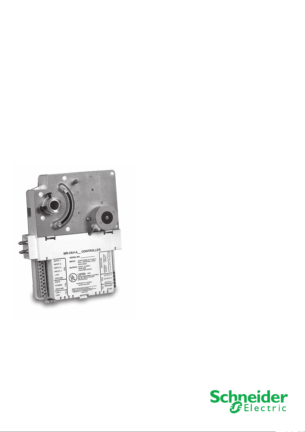
MR-VAV-AX
Application Specific MicroRegulator
TAC’s MR-VAV-AX Application Specific MicroRegulatorTM has an
extensive range ofpre-engineered VAV control sequences, which
combined with a fully integrated actuator and airflow transducer,
makes it a low “Total Installed Cost” solution for most VAV
terminal unit control applications.
TM

TAC I/NET MR-VAV-AX
Application Specific MicroRegulator
Features
An intelligent I/STATTM interface for
independent local control and an interface
to a TAC I/NET
System are standard options.
TM
Distributed Control
02
PRODUCT AT A GLANCE
• Full y Integr ated Actuato r, Ai rflow Tran sducer
and Controller in a single, low profile package.
• Standalone and Networked Applications
• Extensive VAV Control Sequences:
– Two Stage Heating, Multiple Modes
– Series/Parallel Fan
– Local/Remote Occupancy Override
– Local/Remote Central Plant Heat or Morning
Warm-up Control
– Loc al/Rem ote Shut Down O verride
(fire, failure, etc.)
– Indoor Air Quality Airflow Setpoint Override
– Demand Control Setpoint Override
– Mi nimum a nd Maximum Airfl ow Param eters
for heating and cooling
• Complete “Out-of-the-Box” Installation,
Configuration and Commissioning
– DI P Switc h Confi guratio n and N etwork
Addressing with Local/Remote Override
– Completely mount and secure with one box
screw and two damper shaft screws
– Travel Limit Settings
– Automatic calibration of Airflow and
Temperature Sensors
– Autoconfiguration of Heating Stages
– “Prove It” function for Performance
Verification
– Automatic Database Distribution for
Networked Configurations
– Default Parameter Values
(continued)
Operation
The MR-VAV-AX has been designed to minimize
the total installation, setup, configuration and
commissioning costs typically associated with
VAV controllers.
Installation costs have been reduced by
integrating the actuator, airflow transducer and
controller into a single, low profile, plenum-rated
package that can be completely mounted and
secured with one box screw and two damper shaft
screws.
Setup costs have been reduced by the
provision of DIP switches that can be set during
installation and before power is applied. For most
applications, default parameters will allow the
controller to run immediately from startup based on
these switch settings.
The MR-VAV-AX is also supplied with an
extensive range of pre-engineered and tested
control sequences and therefore, no application
programming is required. All configuration
parameters are pre-installed with the most typical
default values. However, they can be overwritten
either by an I/STAT, an M/STAT (a portable I/
STAT) or the Operator Station PC. Heating stage
setpoints, proportional bands and delays are
automatically calculated and set in the controller
based on the controller setup selection.
Commissioning costs have been reduced
by the use of several automated processes.
Airflow conversion parameters are automatically
calculated once the box duct diameter and the
manufacturer’s K-factor are entered. By measuring
and entering the low and high airflow values for the
box, automatic calibration of the installed airflow
transducer is then performed. Automatic calibration
of the temperature sensor is also initiated once a
measured value is entered into the controller.

TAC I/NET MR-VAV-AX
Application Specific MicroRegulator
03
Features
– Co nfigura tion an d Commi ssioni ng by
I/STAT, M/STAT or PC
– Auto-rescaling of velocity transducer in
low flow applications
– Self-Test Diagnostics
• I/STAT and M/STAT Support Standard
– Local Display - 3 Digit & Decimal
– Local Point Control - Analog or Digital
– Local Override & Setpoint Adjustment
– Service Mode for Commissioning
and Calibration
– User-Defined Passwords
• Slide/STAT Support Standard
– Slide Setpoint Override
– Occupancy Override
– Integral Port for M/STAT Connection
• Inputs
– Integrated Airflow Transducer
– Thermistor or Discrete
• Low Voltage Triac Outputs for
– Series/Parallel Fan Control
– First Stage Heater Control (Two Position,
Frequency Modulated, Pulse Width
Modulated or Floating Control Modes)
– Se cond St age Hea ter Control
(Two Position Control only)
– Integrated Actuator
(continued)
Dimensional Drawing
A “Prove It” function allows a complete verification
of the control sequence from an I/STAT or M/STAT.
Once initiated, the space temperature is placed in
Test Mode and can be “increased” or “decreased”
by the buttons on the I/STAT.
value is changed through the control range, the
I/STAT displays the airflow values and the state
of the fan and auxiliary heating. This allows
confirmation of the thermodynamic process from
end to end.
Schneider Electric
As the temperature

TAC I/NET MR-VAV-AX
Application Specific MicroRegulator
04
Features
Finally, in a networked environment, the database
for the MicroController Interface or an I/SITE LAN
can be automatically generated by an upload of
all the data in the connected Application Specific
MicroRegulators. This database can also include a
unique eight-character name for each controller as
part of each point descriptor.
In a standalone configuration, the controller
provides auxiliary inputs for VAV Shutdown (e.g.
fire alarm), Occupancy Override (e.g. Timer, Pushbutton or Occupancy Sensor) and Central Plant
Heat or Morning Warm-Up Override (e.g. contacts
from a central plant).
In a network environment, these signals can be
provided locally for the standalone mode or via
the network. If these inputs are not used for local
override signals, then they can be designated as
“free” and used for any auxiliary input condition
monitoring desired in a networked environment
(e.g. supply air temperature). This is also applicable
to any unused outputs. They can become
available for control applications resident in the
MCI or I/SITE LAN (e.g. lighting control).
A networked environment of MR-VAV-AX
controllers can provide an extensive range of
global interlocks. These include Demand Mode
setpoint override, Central Plant Heat/Morning
Warm-up, Smoke Control (purge and isolate),
Indoor Air Quality (IAQ), Minimum Airflow setpoint
override, Temperature Setpoint override and
Occupancy override.
(continued)
Model N umber Description
MR-VAV -AX Applic ation Specific M icroRegulato r, 1 I/STAT Port, Integrate d
Airflo w Transduce r, 4 Thermis tor or Discrete Inp uts,
3 Low Voltage Triac Out puts, Integrate d Actuator, 24Vac
TCON 147 Applic ation Specific M icroRegulato r Installation G uide
TCON1 48 Application Sp ecific MicroRe gulator Insta llation Sheet
TCON1 49 Application Sp ecific MicroRe gulator Pocket Gui de
Also, the current damper actuator position is
continuously calculated and available as an Analog
Output value that is a percentage of full damper
stroke. This eliminates the need for expensive
feedback potentiometers and analog voltage
controlled (0-10 Vdc) damper actuators. This
analog output point can be overridden either
manually from an operator station or automatically
via an application program in the MCI or I/SITE
LAN and the actuator driven to any desired
absolute position.
The controller can also provide an analog value of
the current controller loading as a percentage value
of full load for both cooling and heating modes.
This value can be used in the networked system
to provide an accurate signal to the central plant
controllers of actual system load requirements.
hneider Electric
Sc

TAC I/NET MR-VAV-AX
Application Specific MicroRegulator
Specifications
MR-VAV-A X
05
Communication Ports
Microregulator Lan
RS-485, 9600 baud, asynchronous, polling.
Network Wiring Requirements
MR LAN Length
5000 ft (1500 m)
Cable Supported
Twisted pair, shielded. 24 AWG or larger,
30pF/ft or less between conductors,
55pF/ft or less conductor to shield,
85 to 150 Ohm impedance.
Belden 9841 or equivalent
Processor
Processor
Zilog 86C193
Memory
EPROM: 32Kbytes
RAM: 464Bytes
NOVRAM: 4096Bytes.
Physical Description
Dimensions
7.75˝ L x 6.25˝ W x 2.5˝ H
(19.7 cm x 15.9 cm x 6.3 cm).
Enclosure
Meets UL94-5V UL flammability
for plenum applications.
Power Requirements
24Vac, +10%, 50/60 Hz
(9VA, plus triac load, 4A fused)
Operating Temperature
32°F to 122°F (0°C to 50°C)
Operating Humidity
10-90% RH, non-condensing
Software
Point Capacity
20 resident points. Hardware (external)
points are a function of model selected
and software (internal) points activated.
Input/Output
Space Sensor Input
Supports I/STAT, Slide/STAT
or 10K Ohm NTC Thermistor
(Dale 1M1002-C3)
Accuracy: 1°F (0.6°C)
Resolution: 0.32°F (0.18°C) @ 77°F (25°C)
Inputs
May be either thermistor or discrete per
the following specifications.
Analog Inputs
10K Ohm NTC Thermistor
(Dale 1M1002-C3)
Accuracy: 1%
Resolution: 0.4% Span
A/D Digital Filtering: Median value filter
and 60 Hz notch filter
Calibration Coefficients: Factory set in
NOVRAM, field adjustable, 6 individual pairs
Digital Inputs
Dry contact input
Contact Excitation: 5V @ 0.5 mA
Discrete Outputs
Low Voltage Triac: 24Vac @ 0.5A maximum
(voltage sourcing), fused
Point Scan Interval
1-255 seconds
hneider Electric
Sc

TAC I/NET MR-VAV-AX
Application Specific MicroRegulator
06
Specifications
(continued)
MR-VAV-A X
Velocity Pressure Input
Operating Range:
0.0 to 1’’ of W.C. (0 to 250Pa)
Sensitivity: 0.0029’’W.C.
(0.73Pa) below midscale and
0.0049’’W.C. (1.10Pa) above midscale.
Tubing Connections:
Barb fittings for 0.170˝ (4.3 mm) I.D. FRPE
polyethylene tubing or 0.25˝ O.D./0.125˝ I.D.
6.3 mm/3.2 mm) tygon tubing
Tubing Length: 4 ft (1.2 m)
maximum each tube
Actuator Outputs
Torque Rating: 53 lb-in (6 Nm)
Stroke: Fully adjustable from 0° to 95°
Timing: 2 sec/degree rotation (60 Hz),
2.4 sec/degree rotation (50Hz)
Position Indication: Visual Indication
Provided Manual Override: Push-button
clutch release to allow manual positioning
of damper
Damper Linkage: 0.5’’D (12.7 mm) round
shaft extending a minimum of 1’’ (25 mm)
from the box, 3/8’’ shaft adapter optional.
Terminations
Terminal Blocks
Removable screw terminal connectors
Indications
LEDs
MR LAN activity (transmitting & receiving -
each channel), test mode (microprocessor
check, EPROM check, NOVRAM check)
Dip Switch
SW1- 5: Address (0 to 31)
SW6-12: Function Selection
Agency Approval
FCC Part 15
UL916 Energy Management
Equipment UL94-5V UL
Requirements for Plenum Application
MicroRegulator Interface (MRI)
Available Platforms
7792 MRI
7793 MCI
7798 I/SITE LAN
All brand names, trademarks and registered trademarks are the property
without notice.
On October 1st, 2009, TAC became the Buildings Business of its parent company Schneider Electric. This document reflects the visual identity of Schneider Electric,
however there remains references to TAC as a corporate brand in the body copy. As each document is updated, the body copy will be changed to reflect appropriate
corporate brand changes.
Schneider Electric
of their respective owners. Information contained within this document is subject to change
May 2006 pdw
© 200 6-2009 Schneider Electric. All rights reserved.
 Loading...