

Page 1
Page 2

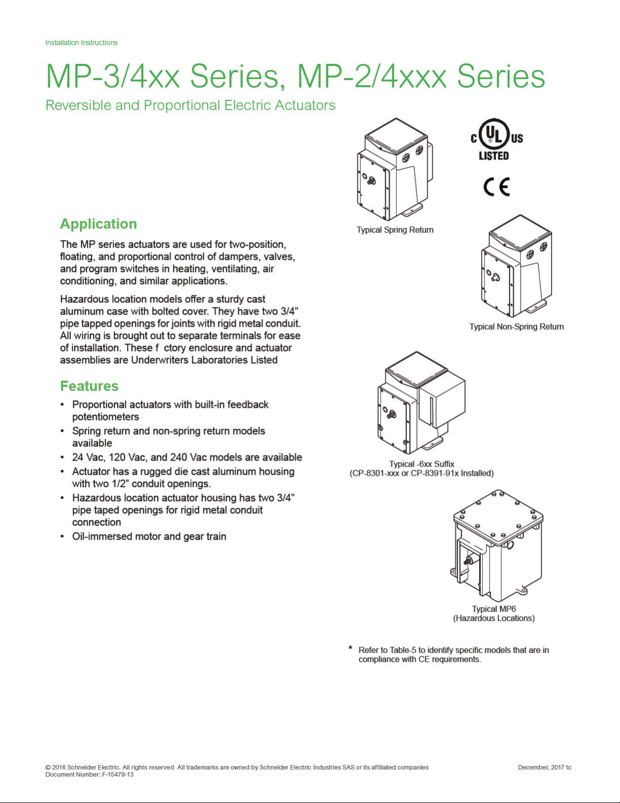
Installation Instructions
SPECIFICATIONS
Actuator Inputs
Input Control Signals: Refer to the actuator selection tables beginning on page 3 for input
control signal capability versus specific actuator models.
Floating, Requires one Single Pole Double Throw (SPDT) switch with floating (center
off) position rated at 0.9 amps @ 24 Vac or two Single Pole Single Throw (SPST)
switches rated at 0.9 amps @ 24 Vac.
Two-Position,
SPDT Requires snap acting switch rated at 0.9 amps @ 24 Vac.
ators. Switch must be rated to
Ω to
SPST Can be used with certain spring return actu
handle actuator power requirements.
Barber-Colman Microtherm, Proportional Electrical system with the following typical
controllers: PP-22x series, TP-1xx series, TP-2xx series, TP-3xx series, TP-4xx series,
TP-1xxx series, and TP-1xxxx series.
Standard Control of a single actuator.
Sequencing Control of two actuators in sequence.
Five-Position Used typically for adjustable minimum position (five positions) of an
economizer actuator.
Slidewire and Paralleling, Requires AE-504 paralleling relay. Refer to AE-504 Solid
State Paralleling Relay General Instructions F-16524. AE-504 accepts 100
Ω slidewires.
1000
Voltage Vdc, Requires CP-8301-xxx series of solid state actuator drives. Refer to
CP-8301 Solid State Actuator Drive General Instructions F-14940. Refer to the
actuator selection tables beginning on page 3.
Current mAdc, Requires CP-8391-xxx series of solid state actuator drives. Refer to the
actuator selection tables beginning on page 3.
Power Requirements: Refer to the actuator selection tables beginning on page 3 to
determine power requirements.
Connections:
MP-3xx, 4xx, 2xxx, 4xxx, Coded screw terminals.
Models with “-600” Suffix, Coded screw terminals except for input signal which are
color coded pigtails.
Actuator Outputs
Torque: Refer to the actuator selection tables beginning on page 3 to determine the
actuator torque rating.
Nominal Damper Area: Actuator selection should be made in accordance with the damper
manufacturer’s specifications.
Stroke (Degrees of Rotation), Refer to the actuator selection tables beginning on page
3 for information on degrees of rotation.
Auxiliary Switch, Refer to the actuator selection tables beginning on page 3 for the
models that include an auxiliary switch. Refer to Table-7 for ratings.
Spring Return: Refer to the actuator selection tables beginning on page 3 for models that
are spring return.
Environment
Ambient Temperature Limits:
Shipping and Storage, -40 to 160 °F (-40 to 71 °C).
Operating, -40 to 136 °F (-40 to 58 °C).
Humidity: 5 to 95% RH, non-condensing.
Locations: NEMA 1.
NEMA 4 for non-spring return actuators with AM-363.
Optional hazardous locations models.
Agency Listings:
US Standard UL 873, Underwriters Laboratories (File #E9429 XAPX, Temperature
ting and Regulating Equipment).
Indica
Canadian Standard C22.2 No. 24: Underwriters Laboratories (File #E429 Category
XAPX7, Temperature Indicating and Regulating Equipment).
European Community, EMC Directive (2004/108/EC). Low Voltage Directive
(2006/95/EC). Refer to Table-5 to identify specific models that are in compliance with CE
requirements.
Hazardous Location Models, UL file #E29291. Designed for use in hazardous
December, 2017 tc © 2016 Schne ider Ele ctric. All rights res erved. All t radema rks are owned by S chneider Electric In dustr ies SAS or its af filiated companies .
Document Number: F-15479-13
Page 3
Installation Instructions
Actuator Drive General Instructions F-22453. The CP-8391-716 has an adjustable span of 4 to 16 mAdc (factory set for 16) and adjustable start
point of 2 to 16 mAdc (factory set for 4). The input signal on CP-8391-716 is optically isolated. Refer to
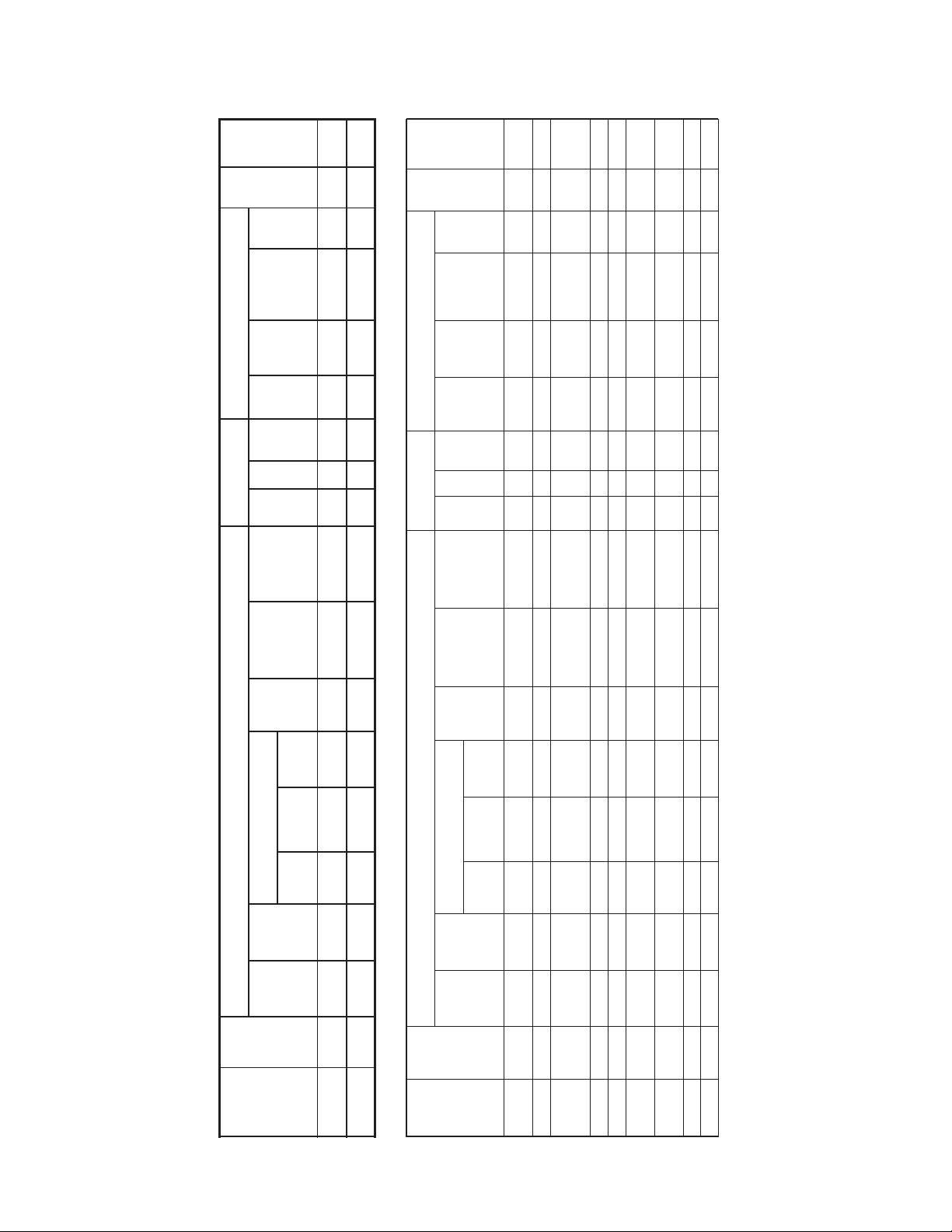
Table-1 MP-2xxx Series Model Chart
Table-2 MP-3xx Series Model Chart.
Input Control Signal External Wiri
MP-2113-500
MP-2150-500
Input Control Signal External Wi
a Typical Barber-Colman Microtherm Controllers: PP-22x Series; TP
b Units with a “-2-x” suffix, e.g. MP-xxxx-xxx-2-x, include a built-in transformer (used for Barber-Colman Microtherm or with AE
8 and Blue (12 Vac) to terminal 7. When these actuators are used with contro
transformer wired directly to potentiometer. To disconnect the transformer, remove the back plate of the actuator, disconnect and tape the transformer leads.
c Requires CP-8391-910.
d Requires CP-8391-716.
e Rotation adjustable 45 to 320
. Caution: On actuators with proportional inpu
f MP-371 models with the “-621” suffix are obsolete.
CP-8391-716 Electronic Actuator Drive
b
Trans-
Built-in
former
tch
Aux.
Swi
Spring
Return
tation
Ro
Degrees of
onds
Timing
Sec
(No Load)
(N-m)
Lb.-in.
Torque
Power
24 60 2.2 50 (5.6) 25 180 (nonAdj.) No SPDT –
Power Requirements Output Shaft
120 60 0.5 50 (5.6) 25 180 (non-Adj.) No SPDT Ye s
d
or
c
Figure-19
Figure-23
Figure-21
(CP-8391-913)
b
ransT
Built-in
former
itch
Aux.
Sw
Spring
Return
) CW SPDT –
) CW SPST –
e
e
Rotation
Degrees of
Output Shaft
Timing
Seconds
(No Load)
(N-m)
Lb.-in.
Torque
Requirements
24 60 2.5 50 (5.6) 90 180 (Adj.
Figure-19
(CP-8391-913)
24 60 2.5 50 (5.6) 90 180 (nonAdj.) CCW SPDT –
Figure-19
(CP-8391-913)
) No SPDT –
) No SPDT –
) No SPST –
e
24 60 2.2 220 (24.9) 130 180 (Adj.
Figure-19
(CP-8391-913)
) No None –
e
e
e
180 (Adj.
(Adj.)
130 to
1300
24 60 2.2 220 (24.9)
Figure-19
(CP-8391-913)
-504) with secondary leads wired externally to terminals 7 and 8 of the actuator. Red (24 Vac) to terminal
Figure-17
(CP-8301-024)
(AE-504)
Figure-14
Position)
Actuators
Figure-27 – Figure-5 Figure-7 – –
Figure-18
(CP-8301-120)
(AE-504)
Figure-15
Figure-29 – Figure-6 – – –
required Interface Module that must be purchased separately)
ring (and
135 to
a
(See Figure)
(Proportional Electric)
Barber-Colman Microtherm
or
2-Position
SPST
2-Position
ng
(See
Wiri
Internal
Part
Actuator
Voltage Vdc Current mAdc Vol ts Hz. Amps
1,000 Ω
Slidewire
Min
(Adj.
Position)
5-Position
wo
of T
Actuators
Sequencing
Standard
oating
SPDT
Fl
Spring
Return
Figure)
Number
Figure-17
Figure-14
(CP-8301-024)
(AE-504)
Figure-14
MP-367 Figure-32 – – – Figure-11 – – – – 24 60 2.5 50 (5.6) 90 180 (Adj.
MP-361 Figure-24 Figure-3 Figure-5 Figure-7 – –
locations N.E.C., Class 1, Groups C and D, and Class 2, Groups E, F, and G. Temperature code T6 for hazardous housing. Actuators in the
actuator selection tables below with “-600” suffix have the CP-8301-120 factory installed. All CP-8301s have a fixed span of 3 Vdc to drive the
actuator full stroke and a start point adjustable from 2 to 12 Vdc (factory set 6 Vdc).
Voltage Vdc Current mAdc Volts Hz. Amps
135 to
1,000 Ω
e Module that must be purchased separately)
(See Figure)
ng (and required Interfac
.
General Instructions F-21220.
The CP-8391-91x series have a fixed range of 4 to 20 mAdc to drive the actuator full stroke. Refer to CP-8391-910 Series 4 to 20 mA Electronic
Slidewire
a
(Adj. Min
5-Position
of Two
Sequencing
(Proportional Electric)
Barber-Colman Microtherm
Standard
DT
or
SP
Floating
2-Position
SPST
Spring
Return
2-Position
ng
(See
Wiri
Figure)
Internal
Part
Number
Actuator
F-15479-12 © Copyright 2012 Schneider Electric All Rights Reserved.
Figure-17
Figure-17
Figure-17
(CP-8301-024)
(AE-504)
MP-371 Figure-24 Figure-3 Figure-5 Figure-7 – –
(CP-8301-024)
(CP-8301-024)
(AE-504)
(AE-504)
Figure-14
Figure-14
llers other than Barber-Colman Microtherm or AE-504, disconnect the Red and Blue leads and tape off. Note: Models prior to “-2-x” suffix had
-1xx Series; TP-4xx Series; TP-101x Series; TP-103x Series; and TP-1xxxx Series.
MP-379 Figure-30 – – – – Figure-12 – – – 24 60 2.5 50 (5.6) 90 180 (nonAdj.) CCW None –
MP-381 Figure-24 – Figure-5 – – –
MP-377 Figure-32 – – – Figure-11 – – – – 24 60 2.5 50 (5.6) 90 180 (nonAdj.) CCW SPST –
MP-389 Figure-30 – – – – Figure-12 – – – 24 60 2.2 220 (24.9) 130 180 (Adj.
MP-382 Figure-24 – Figure-5 – – –
MP-387 Figure-32 – – – Figure-11 – – – – 24 60 2.2 220 (24.9) 130 180 (Adj.
t signals changing the rotation will affect the control, since the internal feedback potentiometer’s travel is fixed.
°
© 2016 Schne ider Ele ctric. All rights res erved. All t radema rks are owned by S chneider Electric Industr ies SAS or its af filiated companies . December, 2017 tc
Docume nt Number: F-15479 -13
Page 4

Installation Instructions
Table-3 MP-4xx Series Model Chart.
Actuator
Number
Input Control Signal External Wiring (and requ
MP-461-600
MP-471-600
MP-481-600
Footnotes for this table are listed on the following page.
b
ransT
Built-in
former
Aux.
Switch
Spring
Return
) No SPDT –
) No SPDT –
e
) No SPDT –
e
e
) No SPDT –
) No SPDT –
e
) No SPDT –
e
) No SPDT –
e
e
) CW SPDT –
) No SPDT –
e
) CW SPDT Ye s
e
e
) No None Ye s
) No SPDT –
e
e
) No SPDT Ye s
) No SPDT Ye s
) No SPDT Ye s
e
e
) No SPDT Ye s
e
e
ation
Rot
Degrees of
180 (Adj.
90 (Adj.
180 (Adj.
90 (Adj.
180 (Adj.
Output Shaft
Power
Requirements
e Module that must be purchased
a
ired Interfac
separately)
(See Figure)
conds
Timing
Se
(No Load)
-in.
(N-m)
Lb.
Torque
Vol ts Hz. Amps
mAdc
Current
Voltage Vdc
135 to
1,000 Ω
Slidewire
5-Position
ing
Sequenc-
(Adj.)
25 to 250
120 60 0.65 60 (6 8) 25 180 (Adj.
120 60 0.65 60 (6 8)
d
d
or
or
c
c
Figure-22
Figure-22
Figure-20
Figure-20
Figure-16
Figure-16
(CP-8301-120)
(CP-8301-120)
(Adj. Min
Position)
of Two
Actuators
c
or
Figure-20
Figure-16
120 60 0.65 60 (6 8) 13 90 (Adj.
d
Figure-22
(CP-8301-120)
13 to 130
or
c
Figure-20
Figure-16
120 60 0.65 60 (6 8)
d
(Adj.)
Figure-22
(CP-8301-120)
c
120 60 0.6 220 (24.9) 130 180 (Adj.
d
or
Figure-21
Figure-18
Figure-15
Figure-23
(CP-8301-120)
(AE-504)
130 to 1300
120 60 0.6 220 (24.9)
d
or
c
Figure-21
Figure-18
Figure-15
(Adj.)
Figure-23
(CP-8301-120)
(AE-504)
or
c
Figure-21
Figure-18
Figure-15
120 60 0.95 450 (50.9) 130 180 (Adj.
d
Figure-23
(CP-8301-120)
(AE-504)
(Adj.)
80 to 800
120 60 0.65 220 (24.9) 80 180 (Adj.
120 60 0.65 220 (24.9)
d
d
or
or
c
c
Figure-22
Figure-22
Figure-20
Figure-20
Figure-16
Figure-16
(CP-8301-120)
(CP-8301-120)
c
or
Figure-20
Figure-16
120 60 0.65 220 (24.9) 40 90 (Adj.
d
Figure-22
(CP-8301-120)
c
40 to 400
or
Figure-20
Figure-16
120 60 0.65 220 (24.9)
(Adj.)
d
Figure-22
(CP-8301-120)
120 60 0.6 50 (5.6) 90 180 (Adj.
d
or
c
– 120 60 0.6 50 (5.6) 90 180 (Adj.
Figure-23
Figure-21
f
Figure-18
(CP-8301-120)
(AE-504)
Figure-15
120 60 0.6 50 (5.6) 90 180 (non-Adj.) CCW SPDT Ye s
d
or
c
– 120 60 0.6 50 (5.6) 90 180 (non-Adj.) CCW SPDT –
Figure-23
Figure-21
f
Figure-18
(CP-8301-120)
(AE-504)
Figure-15
120 60 0.6 220 (24.9) 65 90 (Adj.
d
or
c
– 120 60 0.6 220 (24.9) 130 180 (Adj.
Figure-23
Figure-21
f
Figure-18
(CP-8301-120)
(AE-504)
Figure-15
(Proportional Electric)
Barber-Colman Microtherm
December, 2017 tc © 2016 Schne ider Ele ctric. All rights res erved. All t radema rks are owned by S chneider Electric In dustr ies SAS or its af filiated companies .
Document Number: F-15479-13
Internal
Standard
or
oating
SPDT
Fl
2-Position
– Figure-6 – – –
Figure-26
g
MP-486 Figure-26 – Figure-6 – – –
MP-495
SPST
Spring
Return
2-Position
(See
Wiring
Figure)
Part
MP-421 Figure-25 – Figure-6 – – – –
MP-422 Figure-25 – Figure-6 – – – –
MP-424 Figure-25 – Figure-6 – – – –
MP-423 Figure-25 – Figure-6 – – – –
MP-451 Figure-25 – Figure-6 – – – –
MP-452 Figure-25 – Figure-6 – – – –
MP-453 Figure-25 – Figure-6 – – – –
Figure-25 – 1 5 – – – – Figure-16
MP-454 Figure-25 – Figure-6 – – – –
Figure-25 – – – – – – Figure-16
MP-465 Figure-26 Figure-4 Figure-6 Figure-9 – –
MP-470 Figure-31 – – – – Figure-13 – – – 120 60 0.6 50 (5.6) 90 180 (non-Adj.) CCW None Ye s
Figure-25 – – – – – – Figure-16
MP-485 Figure-26 – Figure-6 – – –
MP-475 Figure-26 Figure-4 Figure-6 Figure-9 – –
MP-483 Figure-26 – Figure-6 – – –
MP-480 Figure-31 – – – – Figure-13 – – – 120 60 0.6 220 (24.9) 130 180 (Adj.
Page 5
Installation Instructions
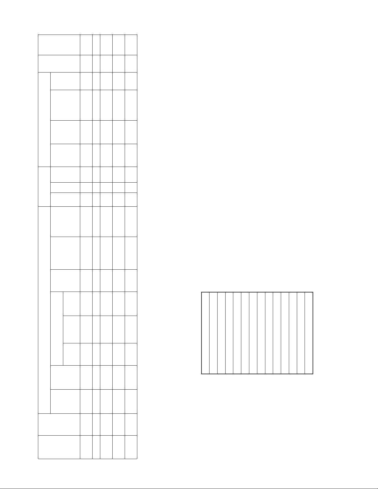
Table-4 MP-4xxx Series Model Chart.
Tabl e - 5 Actuator Part Numbers that are Compliant with CE
Actuator
Number
Input Control Signal External Wiring (and required Inte
MP5-4651
MP-4701
MP5-4751
MP-4851
MP5-4851
a Typical Barber-Colman Microtherm Controllers: PP-22x Series; TP-1
b Units with a “-2-x” suffix, e g. MP-xxx
terminal 8 and Blue (12 Vac) to terminal 7. When these actuat
transformer wired directly to potentiometer. To disconnect the tr
c Requires CP-8391-910.
d Requires CP-8391-716.
e Rotation adjustable 45 to 320
. Caution: On actuators with propor ional input signals changing the rotation will affect he control, since the internal feedb
f Integral solid state drive accepts 2-15 Vdc voltage.
g MP-495 is not rated for UL or CSA
b
Tra ns -
Built-in
former
Aux.
Switch
Spring
Return
Degrees of
) CW SPDT Yes
f
Rotation
) No SPDT Yes
) No SPDT Yes
f
f
Output Shaft
Timing
Seconds
(No Load)
(N-m)
Lb.-in.
Torque
ack potentiometer’s travel is fixed.
Power
Requirements
Vol ts Hz. Amps
240 50 0.25 50 (5.6) 108 180 (Adj.
d
or
c
240 50 0.25 50 (5.6) 108 180 (non-Adj ) CCW SPDT Yes
240 60 0.25 220 (24 9) 130 180 (Adj.
240 50 0.25 220 (24 9) 156 180 (Adj.
or
d
d
d
or
c
or
c
c
rface Module that must be purchased separately)
(See Figure)
mAdc
Current
Voltage Vdc
135 to
1,000 Ω
Slidewire
a
5-Position
Figure-23
Figure-21
Figure-18
(CP-8301-240)
(AE-504)
Figure-15
(Adj. Min
Position)
Figure-21
Figure-18
Figure-15
Figure-23
(CP-8301-240)
(AE-504)
Figure-21
Figure-18
Figure-15
Figure-23
(CP-8301-240)
(AE-504)
Figure-21
Figure-18
Figure-15
Figure-23
(CP-8301-240)
(AE-504)
xx Series; TP-4xx Series; TP-101x Series; TP-103x Series; and TP-1xxxx Series.
of Tw o
Actuators
Sequencing
(Proportional Electric)
ors are used with controllers other han Barber-Colman Micro herm or AE-504, disconnect the Red and Blue leads and tape off. Note: Models prior to “-2-x” suffix had
ansformer, remove the back plate of the actuator, disconnect and tape the transformer leads.
MP-361-0-0-2
MP-363-0-0-2
MP-367-0-0-2
MP-371-0-0-2
MP-377-0-0-2
MP-379-0-0-2
MP-381-0-0-2
MP-382-0-0-2
MP-383-0-0-2
MP-387-0-0-2
MP-389-0-0-2
MP-481-600-0-2
MP-481-691-0-2
MP-481-692-0-2
Barber-Colman Microtherm
Standard
2-Position
or
SPDT
Floating
x-xxx-2-x, include a built-in transformer (used for Barber-Colman Microtherm or with AE-504) wi h secondary leads wired externally to terminals 7 and 8 of he actuator. Red (24 Vac) to
SPST
Spring
Return
2-Position
(See
Wiring
Figure)
Internal
Figure-26 Figure-4 Figure-6 – – –
Figure-31 – – – – Figure-13 – – – 240 60 0.25 50 (5.6) 90 180 (non-Adj ) CCW None Yes
Figure-26 Figure-4 Figure-6 – – –
Figure-26 – Figure-6 – – –
Figure-26 – Figure-6 – – –
Part
© 2016 Schne ider Ele ctric. All rights res erved. All t radema rks are owned by S chneider Electric Industr ies SAS or its af filiated companies . December, 2017 tc
Docume nt Number: F-15479 -13
Page 6

Page 7

Page 8

Page 9

ACCESSORIES
Damper linkage accessories
AM-111 Crank arm for 5/16" (7.9 mm) diameter damper shaft
AM-112 Crank arm for 3/8" (9.5 mm) diameter damper shaft
AM-113 Crank arm for actuator or 1/2" (12.7 mm) diameter damper shaft
AM-115 Crank arm for 7/16" (11.1 mm) diameter damper shaft
AM-116 Splined crank arm for actuator
AM-122 Linkage connector, straight type
AM-123 Damper clip
AM-125 5/16" x 20" (7.9 mm x 0.5 m) damper rod
AM-125-048 5/16" x 48" (7.9 mm x 1.2 m) damper rod
AM-132 Ball joint connector
AM-161 Damper linkage kit
AM-161-1 Damper linkage kit
AM-301 90 degree mounting bracket
Miscellaneous actuator accessories
AM-321 Two step switch kit
AM-332 Potentiometer kit
AM-341 Four step switch kit
AM-342 Two step switch and potentiometer kit
AM-363 NEMA 4 gasket kit for non-spring return actuators only
Valve linkage for 50 lb.-in. minimum, 180 actuator
AV-329 Valve linkage for 2-1/2" and 3" VB-9323
AV-391 Valve linkage for 15 to 50 mm and 1/2" to 2” VB-72xx or VB-73xx (also valve
linkage for
obsolete 1/2” to 1-1/4" VB-92xx or VB-93xx)
AV-392 Valve linkage for obsolete 1-1/2" and 2" VB-92xx or VB-93xx
AV-395 Valve linkage for 65 and 80 mm VB-9215 or VB-9315, and 2-1/2" to 4" VB-9213 or
VB-9313
Valve linkage for 130 lb.-in. minimum, 180 actuator
AV-330 Valve linkage for 2-1/2" and 3" VB-9323
AV-352 Valve linkage for 2-1/2" to 6" VB-921x or VB-931x, 4" to 6" VB-9323
AV-393 Valve linkage for 15 to 50 mm and 1/2” to 2” VB-72xx or VB-73xx (also valve
linkage for
obsolete 1/2" to 1-1/4" VB-92xx or VB-93xx)
AV-394 Valve linkage for obsolete 1-1/2" and 2" VB-92xx or VB-93xx
AV-396 Valve linkage for 65 and 80 mm VB-9215 or VB-9315, and 2-1/2" to 4" VB-921x or
VB-931x
Valve Linkage for 50 lb.-in. MP6-xxx and MP7-xxx Hazardous Location Actuators
AV-291 Valve linkage for ½ to 2" VB-7xxx valves assemb
led with hazardous location
actuator assemblies.
AV-295 Valve linkage for 2½ to 3" VB-9xxx valves assembled with hazardous location
actuator assemblies.
Valve Linkage for 220 lb.-in. MP6-xxx and MP7-xxx Hazardous Location Actuators
AV-293 Valve linkage for ½ to 2" VB-7xxx valves assemb
led with hazardous location
actuator assemblies
AV-296 Valve linkage for 2½ to 3" VB-9xxx valves assembled with hazardous location
actuator assemblies
Installation Instructions
© 2016 Schne ider Ele ctric. All rights res erved. All t radema rks are owned by S chneider Electric Industr ies SAS or its af filiated companies . December, 2017 tc
Docume nt Number: F-15479 -13
Page 10

Installation Instructions
TYPICAL APPLICATIONS (wiring diagrams)
List of Figures
Figure-3 External Wiring for SPST Control of MP-361 and MP-371, 24 Vac
Actuators.
Figure-4 External Wiring for SPST Control of MP-465, MP-475, MP5-4651, and
Figure-5 External Wiring for SPDT (Snap Acting or Floating) Switch for Control of
Figure-6 External Wiring for SPDT (Snap Acting or Floating) Switch for Control of
Figure-7 Barber-Colman Microtherm Controller with 24 Vac Actuators – Standard
Figure-8 Barber-Colman Microtherm Controller with 24 Vac Actuators – Reversed
Figure-9 External Wiring of Barber-Colman Microtherm Controller with Line
Figure-10 External Wiring of Barber-Colman Microtherm Controller with Line
Figure-11 External Wiring for Barber-Colman Microtherm Controller with 24 Vac
Figure-12 External Wiring for Barber-Colman Microtherm Controller with
Figure-13 External Wiring for Barber-Colman Microtherm Controller with
Figure-14 External Wiring for Slidewire Controller with 24 Vac Actuators. page 18
Figure-15 External Wiring for Slidewire Controller with Line Voltage Actuator. page 18
Figure-16 External Wiring for CP-8301-120, Vdc Interface with Line Voltage
Figure-17 External Wiring for CP-8301-024, Vdc Interface with 24 Vac Actuators. page 20
Figure-18 External Wiring for CP-8301-120 and CP-8301-240, Vdc Interface with
Figure-19 External Wiring for CP-8391-913, 4 to 20 mAdc Interface with 24 Vac
Figure-20 External Wiring for CP-8391-910, 4 to 20 mAdc Interface with Line
Figure-21 External Wiring for CP-8391-910 and CP-8391-911, 4 to 20 mAdc
Figure-22 External Wiring for CP-8391-716, mAdc Interface with Line Voltage
Figure-23 External Wiring for CP-8391-716, mAdc Interface with Line Voltage
Figure-24 Internal Wiring for 24 Vac Actuator. page 24
Figure-25 Internal Wiring for Line Voltage Actuators. page 25
Figure-26 Internal Wiring for Line Voltage Actuator with Built-in Transformer. page 25
Figure-27 Internal Wiring for 24 Vac Actuator without Limit
Figure-28 Internal Wiring for Line Voltage Actuators without Limit Switches
Figure-29 Internal Wiring for Line Voltage Actuators without Limit Switches and
Figure-30 Internal Wiring for 24 Vac Five-Position Actuators. page 27
Figure-31 Internal Wiring for LIne Voltage Five-Position Actuators. page 28
Figure-32 Internal Wiring for 24 Vac Sequencing Actuators. page 28
MP5-4751 Line Voltage Actuators.
24 Vac Actuators MP-361, MP-371, MP-381, MP-382 and MP-2113-500.
Line Voltage Actuators.
Wiring Diagram.
(Cooling) Wiring Diagram.
Voltage Actuator – Standard Wiring.
Voltage Actuator – Reversed (Cooling) Wiring.
Sequencing Actuators.
Five-Position 24 Vac Actuators.
Five-Position Line Voltage Actuator.
Actuators without Internal Transformer.
Line Voltage Actuators with Internal Transformer.
Actuators.
Voltage Actuators without Internal Transformer.
Interface with Line Voltage Actuators with Internal Transformer.
Actuators without Internal Transformer.
Actuators with Internal Transformer.
Switches (Actuator is
Stall Type with Built-in Mechanical Stops).
(Actuator is Stall Type with Built-in Mechanical Stops.)
Built-in Transformer (Actuator is Stall Type with Built-in Mechanical
Stops).
page 11
page 11
page 12
page 12
Page 13
page 13
page 14
page 14
page 15
page 16
page 17
page 19
page 21
page 22
page 22
page 23
page 23
page 24
page 26
page 26
page 27
December, 2017 tc © 2016 Schne ider Ele ctric. All rights res erved. All t radema rks are owned by S chneider Electric In dustr ies SAS or its af filiated companies .
Document Number: F-15479-13
Page 11

Page 12

Page 13

Page 14

Page 15

Page 16

Page 17

Page 18

Page 19

Page 20

Page 21

Page 22

Page 23

Page 24

Page 25

Page 26

Page 27

Page 28

Page 29

Page 30

Page 31

Page 32

Page 33

Page 34

Installation Instructions
Power Wiring All actuators include a barrier that separates the power wiring compartment from the low
voltage wiring compartment. Refer to Table-10 for allowable circuit class for the two wiring
compartments.
Table-10 Actuator Circuit Class.
Power Wiring Compartment Low Voltage Wiring Compartment
Typical Part Numbers
MP-361, MP-371,
81, MP-382,
MP-3
MP-2113-500
MP-421, MP-422,
23, MP-424,
MP-4
MP-451, MP-452,
MP-453, MP-454,
MP-461-600, MP-465,
MP-471-600, MP-475,
MP-481-600, MP-483,
MP-485, MP-486,
MP-495, MP-2150-500,
MP5-4651, MP5-4751,
MP-4851, MP5-4851
MP-367, MP-377,
MP-379, MP-389
MP-470, MP-480,
MP-38
MP-4701
7
Actuator
Description
Low Voltage
Proportional
Line Voltage
oportional
Pr
Low Voltage
Sequencing
Low Voltage
F
ive-Position
Line Voltage
Five-Position
Terminals (Function)
H&G (24 Vac Power)
1, 5, and 6
(Auxiliary Switch)
L1 and L2
oltage Power)
(Line V
1, 5, and 6
uxiliary Switch)
(A
H&G (24 Vac Power)
1, 5, and 6
Control Switches)
(
H&G (24 Vac Power)
6, 7, and 8
(Potentiometer)
H&G (24 Vac Power)
6, 7, and 8
Potentiometer)
(
Circuit Class for
Power Wiring Compartment
1.May be Class 2 circ
auxiliary switch is wired to
24 Vac or is not used.
2.Must be Class 1 circuit if
auxiliary switch is wired to line
voltage.
Must be Class 1 circuit.
May be Class 2 Circuit.
May be Class 2 Circuit.
Must be Class 1 Circuit.
uit if
Terminals (Function)
X, 2, and 3
(Control Circuit)
4, 7, and 8
(Potentiometer)
X, 2, and 3
(
Control Circuit)
4, 7, and 8
(Potentiometer)
X, 2, and 3
(
Control Circuit)
4, 7, and 8
(Potentiometer)
X, 1, 2, 3, 4, 5
(Control Circuit)
X, 1, 2, 3, 4, 5
(
Control Circuit)
Circuit Class
for Low
Voltage Wiring
Compartment
May be Class 2
Circuit.
May be Class 2
Circuit.
May be Class 2
Circuit.
May be Class 2
Circuit.
May be Class 2
Circuit.
Refer to Table-11 for selection of proper gage wire for
the length of wire run (one run has two
wires).
Table-11 Power Wire Selection.
Actuator Series Voltage
MP-36x, MP-37x 24 Vac
MP-38x 24 Vac
MP-42x
MP-445-304
MP-45x
MP-46x
MP-47x
MP-48x
MP-4xx1 240 Vac 14 3340 (1018)
120 Vac
120 Vac
Wire Size
(AWG)
14
12
10
14
12
10
14
12
10
14
12
10
Maximum
Run ft. (m)
115 (35)
180 (55)
285 (87)
130 (40)
205 (62)
325 (99)
810 (247)
1275 (388)
2040 (622)
1050 (320)
1660 (506)
2650 (808)
When multiple 24 Vac actuators are powered from the same transformer, the actuators must
be in phase. Connect the same transformer lead to the “G” terminal on all actuators and
same transformer lead to the “H” terminal on all actuators.
December, 2017 tc © 2016 Schne ider Ele ctric. All rights res erved. All t radema rks are owned by S chneider Electric In dustr ies SAS or its af filiated companies .
Document Number: F-15479-13
Page 35

Control Wiring Refer to Figure-3 through Figure-23 for typical wiring of the actuators. Refer to the actuator
selection tables beginning on page 3, for an index of External Wiring Figures versus actuator
models and control signals. The requirements for the field control wiring are shown below.
SPST Control Signal
Refer to Figure-3 and Figure-4. Since the SPST switch is controlling the power to the
actuator, the control wiring is limited to the power wiring shown above.
SPDT Control Signal
Refer to Figure-5 and Figure-6. Use 18 gage wire for runs up to 1,000 ft. (305 m) between
the actuator and the SPDT switch. Use larger gage wires on longer runs.
Barber-Colman Microtherm Control
Refer to External Wiring Figure-7 through Figure-13. Use 18 gage wire for runs up to
1,000 ft. (305 m) between the actuator and the Barber-Colman Microtherm controller. Use
larger gage wires on longer runs.
135 to 1000 Ω Slidewire Control
Refer to External Wiring Figure-14 and Figure-15. Use 18 gage three-conductor twisted
leads (part number W-103 or equal) for runs up to 500 ft. (152 m) between the actuator and
the slidewire controller. Use larger gage wires for longer runs.
Voltage Vdc Control
Refer to External Wiring Figure-16 through Figure-18. Use 18 gage three-conductor twisted
leads (part number W-103 or equal) for runs up to 1,000 ft. (305 m) between the actuator
and the Vdc controller. Use larger gage wires for longer runs.
Installation Instructions
Caution: Use 18 gage three-conductor shielded cable (twisted) when it is necessary to
install the control leads in the same conduit with power wiring, or when high RFI/EMI
generating devices are near. Do not connect the shield to earth ground or any leads or
terminals.
Current mAdc Control
Refer to External Wiring Figure-19 through Figure-23. Use 18 gage two-conductor twisted
leads (part number W-102 or equal) for runs up to 500 ft. (152 m) between the actuator and
the slidewire controller. Use larger gage wires for longer runs.
Direct Digital Control (DDC)
DDC controllers may be used to control these actuators according to one of the methods
described below.
SPST Control
Refer to External Wiring Figure-5 and Figure-6. Requires two digital output points
programmed as a drive open, drive closed configuration. The digital output must be rated for
switching 0.9 amp at 24 Vac .
Voltage Vdc Control
Refer to External Wiring Figure-16, Figure-17, and Figure-18. Requires an analog output
from the DDC controller, programmed to provide the desired voltage range. Also requires a
CP-8301-120 electronic actuator drive between the DDC controller and the actuator.
Current mAdc Control
Refer to External Wiring Figure-19, Figure-20, and Figure-21. Requires an analog output
from the DDC controller, programmed to provide the desired current range (usually 4 to 20
mA). Also requires a CP-8391-913 electronic actuator drive between the DDC controller and
the actuator.
© 2016 Schne ider Ele ctric. All rights res erved. All t radema rks are owned by S chneider Electric Industr ies SAS or its af filiated companies . December, 2017 tc
Docume nt Number: F-15479 -13
Page 36

Page 37

Page 38

Page 39

CHECKOUT
After the entire system has been installed and the actuator has been powered up, the
following checks can be made for proper system operation.
GO, NO GO Test Slidewire Controller with 24 Vac Actuators
Refer to Figure-14.
1. Disconnect field wiring from Brown lead of AE-504 and terminals 7 and 8 of the actuator.
2. Apply 24 Vac power to terminals H and G of the actuator.
3. Short the Brown lead of AE-504 to terminal 7 of actuator and the actuator should rotate
CW to its limit.
4. Short the Brown lead of AE-504 to terminal 8 of actuator and the actuator should rotate
CCW to its limit.
5. If the unit passes steps 3 and 4, the actuator and the AE-504 are good. If the unit does
not pass steps 4 and 5, proceed to step 6.
6. Unhook the AE-504 leads from actuator terminals X, 2, and 3.
7. Short actuator terminal X to 2 and the actuator should rotate CW to its limit.
8. Short actuator terminal X to 3 and the actuator should rotate CCW to its limit.
If the unit passes steps 7 and 8, the actuator is good and AE-504 is defective. If the unit does
not pass steps 7 and 8, the actuator is defective and the AE-504 may be good.
Installation Instructions
Slidewire Controller with Line Voltage Actuator
Refer to Figure-15.
1. Disconnect field wiring from Brown lead of AE-504 and terminals 7 and 8 of the actuator.
2. Apply proper AC power to terminals L1 and L2 of the actuator.
3. Short the Brown lead of AE-504 to terminal 7 of actuator and the actuator should rotate
CW to its limit.
4. Short the Brown lead of AE-504 to terminal 8 of actuator and the actuator should rotate
CCW to its limit.
5. If the unit passes steps 3 and 4, the actuator and the AE-504 are good. If the unit does
not pass steps 4 and 5, proceed to step 6.
6. Unhook the AE-504 leads from actuator terminals X, 2, and 3.
7. Short actuator terminal X to 2 and the actuator should rotate CW to its limit.
8. Short actuator terminal X to 3 and the actuator should rotate CCW to its limit.
If the unit passes steps 7 and 8, the actuator is good and AE-504 is defective. If the unit does
not pass steps 7 and 8, the actuator is defective and the AE-504 may be good.
CP-8301-120, Vdc Interface with Line Voltage Actuators without Internal
Transformer
Refer to Figure-16.
1. Disconnect field wiring from Red, Yellow, and Blue leads of CP-8301-xxx.
2. Apply 120 Vac power to terminals L1 and L2 of the actuator.
3. Short the Yellow and Red leads of CP-8301-xxx and the actuator should rotate CW to
its limit, unless rewired to rotate CCW on an increase in input signal.
4. Short the Yellow and Blue leads of CP-8301-xxx and the actuator should rotate CCW to
its limit, unless rewired to rotate CCW on an increase in input signal.
5. If the unit passes steps 3 and 4, the actuator and the CP-8301-xxx are good. If the unit
does not pass steps 3 and 4, proceed to step 6.
6. Unhook the CP-8301-xxx leads from actuator terminals X, 2, and 3.
7. Short actuator terminal X to 2 and the actuator should rotate CW to its limit.
© 2016 Schne ider Ele ctric. All rights res erved. All t radema rks are owned by S chneider Electric Industr ies SAS or its af filiated companies . December, 2017 tc
Docume nt Number: F-15479 -13
Page 40

Installation Instructions
8. Short actuator terminal X to 3 and the actuator should rotate CCW to its limit.
If the unit passes steps 7 and 8, the actuator is good and CP-8301-xxx is defective. If the
unit does not pass steps 7 and 8, the actuator is defective and the CP-8301-xxx may be
good.
CP-8301-024, Vdc Interface with 24 Vac Actuators
Refer to Figure-17.
1. Disconnect field wiring from Red, Yellow, and Blue leads of CP-8301-xxx.
2. Apply 24 Vac power to terminals H and G of the actuator.
3. Short the Yellow and Red leads of CP-8301-xxx and the actuator should rotate CW to
its limit, unless rewired to rotate CCW on an increase in input signal.
4. Short the Yellow and Blue leads of CP-8301-xxx and the actuator should rotate CCW to
its limit, unless rewired to rotate CCW on an increase in input signal.
5. If the unit passes steps 3 and 4, the actuator and the CP-8301-xxx are good. If the unit
does not pass steps 3 and 4, proceed to step 6.
6. Unhook the CP-8301-xxx leads from actuator terminals X, 2, and 3.
7. Short actuator terminal X to 2 and the actuator should rotate CW to its limit.
8. Short actuator terminal X to 3 and the actuator should rotate CCW to its limit.
If the unit passes steps 7 and 8, the actuator is good and CP-8301-xxx is defective. If the
unit does not pass steps 7 and 8, the actuator is defective and the CP-8301-xxx may be
good.
CP-8301-120 and CP-8301-240, Vdc Interface with Line Voltage Actuators
with Internal Transformer
Refer to Figure-18.
1. Disconnect field wiring from Red, Yellow, and Blue leads of CP-8301-xxx.
2. Apply AC power to terminals L1 and L2 of the actuator.
3. Short the Yellow and Red leads of CP-8301-xxx and the actuator should rotate CW to
its limit, unless rewired to rotate CCW on an increase in input signal.
4. Short the Yellow and Blue leads of CP-8301-xxx and the actuator should rotate CCW to
its limit, unless rewired to rotate CCW on an increase in input signal.
5. If the unit passes steps 3 and 4, the actuator and the CP-8301-xxx are good. If the unit
does not pass steps 3 and 4, proceed to step 6.
6. Unhook the CP-8301-xxx leads from actuator terminals X, 2, and 3.
7. Short actuator terminal X to 2 and the actuator should rotate CW to its limit.
8. Short actuator terminal X to 3 and the actuator should rotate CCW to its limit.
If the unit passes steps 7 and 8, the actuator is good and CP-8301-xxx is defective. If the
unit does not pass steps 7 and 8, the actuator is defective and the CP-8301-xxx may be
good.
CP-8391-xxx Series mAdc Interface
Refer to Figure-19 through Figure-23.
1. Unhook the CP-8391-xxx leads from actuator terminals X, 2, and 3.
2. Refer to specific actuator for power hook-ups.
3. Short actuator terminal X to 2 and the actuator should rotate CW to its limit.
4. Short actuator terminal X to 3 and the actuator should rotate CCW to its limit.
5. If the unit passes steps 3 and 4, the actuator is good.
December, 2017 tc © 2016 Schne ider Ele ctric. All rights res erved. All t radema rks are owned by S chneider Electric In dustr ies SAS or its af filiated companies .
Document Number: F-15479-13
Page 41

Installation Instructions
Positioning the
Actuator with the
Controller
If the sensed media is within the controller’s setpoint range, the actuator can be positioned
by adjusting the controller setpoint up and down. Check for proper operation of the actuator
(valve or damper) while the actuator is being stroked.
Theory of Operation
Actuator variations are shown in Figure-24 through Figure-32. Refer to the actuator
selection tables beginning on page 3 to determine which Internal Wiring Figure applies to a
certain actuator.
The actuators are powered by shaded pole motors that are of the induction type, using what
is commonly know as a squirrel cage rotor. These motors, like all single phase induction
motors, must be provided with some means of starting. This is accomplished by the shading
coils in the poles of the motor and hence the name “Shaded Pole.” However, unlike most
single phase induction motors, the shading coils are also essential for running.
The field coil produces a magnetic field in the iron core (stator) and in the rotor. When
actuator terminal x is shorted to a terminal attached to CW shading coils, it causes a lag in
part of the field which provides the equivalent of a rotating field. This rotating field induces a
voltage and current in the rotor bars, and the attraction between the rotating field and these
current carrying bars pulls the rotor around with the field in a CW direction. When actuator
terminal x is shorted to a terminal attached to CCW shading coils, it operates the same
except it drives the actuator CCW. A voltage of 24 to 30 Vac with current of 9 amps is induced
in the shading coils in much the same manner as the secondary of a transformer.
© 2016 Schne ider Ele ctric. All rights res erved. All t radema rks are owned by S chneider Electric Industr ies SAS or its af filiated companies . December, 2017 tc
Docume nt Number: F-15479 -13
Page 42

Installation Instructions
REPLACEMENT PARTS
Table-12 Potentiometer Kit.
Actuator
MP-xx0x-0-0-1
MP-xx0x-0-2-1
MP-xx1x-0-0-1 ADDA-902-2 100
MP-xx2x-0-0-1 ADDA-902-2 100
MP-xx3x-0-0-1
MP-xx3x-0-2-1
MP-xx4x-0-0-1
MP-xx4x-0-2-1
MP-xx5x-0-0-1
MP-xx5x-0-2-1
MP-xx6x-0-0-1
MP-xx6x-0-2-1
MP-xx7x-0-0-1 ADDA-902-4 50
MP-xx8x-0-0-1
MP-xx8x-0-2-1
MP-xx9x-0-0-1 ADDA-902-2 100
ADDA-902-2 100
ADDA-902-5 100
ADDA-902-5 100
ADDA-902-2 100
ADDA-902-2 100
ADDA-902-2 100
Table-13 Additional Potentiometer Kits.
Potentiometer Kits
Part No. Description
ADDA-902-6 500
ADDA-902-8 1000
ADDA-902-9 500
ADDA-902-10 1000
Potentiometer Kit
Part No. Description
Ω, 180°
Ω, 180°
Ω, 180°
Ω, 90°
Ω, 90°
Ω, 180°
Ω, 180°
Ω, 180°
Ω, 180°
Ω, 180°
Ω, 90°
Ω, 90°
Ω, 180°
Ω, 180°
MAINTENANCE
TROUBLESHOOTING
REPAIR
Regular maintenance of the total system is recommended to assure sustained, optimum
performance.
The actuators require a minimum of maintenance since the motor and gear train are
submerged in oil for continuous lubrication and cooling.
Refer to Section “GO, NO GO Test” on page 39.
None. Replace an inoperable actuator with a functional unit.
December, 2017 tc © 2016 Schne ider Ele ctric. All rights res erved. All t radema rks are owned by S chneider Electric In dustr ies SAS or its af filiated companies .
Document Number: F-15479-13
Page 43

Page 44

Page 45

Page 46

 Loading...