

Page 1
MicroLogic™ 5 and 6 Electronic Trip
r
c
i
Mcigolo
E
2
.5
r
I
%
A
03
>
0
3
>
0
11
>
.
9
2
9
.
3
9
.
4
9
.
5
9
.
1
89
.
7
9
.
6
9
.
Ir
)
o
Ix(
5.
1
2
5.
2
3
4
0
1
8
6
5
d
s
I
)
r
I
x
(
Units—User Guide
Unidades de disparo electrónico MicroLogic™
5 y 6—Guía de usuario
MC
Déclencheurs électroniques MicroLogic
5
et 6—Guide de l’utilisateur
Instruction Bulletin / Boletín de instrucciones /
Directives d’utilisation
48940-312-01
Rev. 05, 01/2020
Retain for future use. / Conservar para uso futuro. / À conserver pour usage ultérieur.
™
Page 2

Page 3
MicroLogic™ 5 and 6 Electronic Trip Units—
r
c
i
Mcigolo
E
2
.5
r
I
%
A
03
>
0
3
>
0
11
>
.
9
2
9
.
3
9
.
4
9
.
5
9
.
1
89
.
7
9
.
69
.
Ir
)
o
Ix(
5.
1
2
5.
2
3
4
0
1
8
6
5
d
s
I
)
r
I
x
(
User Guide
for PowerPact™ H-, J-, and L-Frame Circuit Breakers
Instruction Bulletin
48940-312-01
Rev. 05, 01/2020
Retain for future use.
ENGLISH
™
Page 4
MicroLogic™ 5 and 6 Electronic Trip Units—User Guide —
DANGER
WARNING
CAUTION
NOTICE
Hazard Categories and Special Symbols
ENGLISH
Read these instructions carefully and look at the equipment to become familiar with
the device before trying to install, operate, service or maintain it. The following
special messages may appear throughout this bulletin or on the equipment to warn
of potential hazards or to call attention to information that clarifies or simplifies a
procedure.
The addition of either symbol to a “Danger” or “Warning” safety label indicates that
an electrical hazard exists which will result in personal injury if the instructions are
not followed.
ANSI
IEC
This is the safety alert symbol. It is used to alert you to potential personal injury
hazards. Obey all safety messages that follow this symbol to avoid possible injury
or death.
DANGER indicates a hazardous situation which, if not avoided, will result in
death or serious injury.
WARNING indicates a hazardous situation which, if not avoided, can result in
death or serious injury.
CAUTION indicates a hazardous situation which, if not avoided, can result in
minor or moderate injury.
NOTICE is used to address practices not related to physical injury. The safety
alert symbol is not used with this signal word.
Please Note
FCC Notice
2-EN
NOTE: Provides additional information to clarify or simplify a procedure.
Electrical equipment should be installed, operated, serviced, and maintained only
by qualified personnel. No responsibility is assumed by Schneider Electric for any
consequences arising out of the use of this material.
This equipment has been tested and found to comply with the limits for a Class A
digital device, pursuant to part 15 of the FCC Rules. These limits are designed to
provide reasonable protection against harmful interference when the equipment is
operated in a commercial environment. This equipment generates, uses, and can
radiate radio frequency energy and, if not installed and used in accordance with the
instruction manual, may cause harmful interference to radio communications.
Operation of this equipment in a residential area is likely to cause harmful
interference in which case the user will be required to correct the interference at his
own expense. This Class A digital apparatus complies with Canadian ICES-003.
© 2011–2020 Schneider Electric All Rights Reserved 48940-312-01
Page 5

Table of Contents MicroLogic™ 5 and 6 Electronic Trip Units—User Guide
Table of Contents
SECTION 1:GENERAL INFORMATION ........................................................................................................ 7
Introduction ...................................................................................................... 7
In Rating ........................................................................................................... 8
Control Power .................................................................................................. 9
Backlighting ...................................................................................................... 9
Trip Unit Installation ......................................................................................... 9
Trip Unit Sealing ............................................................................................ 10
MicroLogic Trip Unit Layout ........................................................................... 11
Trip Unit Face .......................................................................................... 11
Navigation Principles ..................................................................................... 13
Lock/Unlock the Settings ......................................................................... 13
Trip Unit Modes ....................................................................................... 13
Mode Selection ........................................................................................ 14
Readout Mode ............................................................................................... 14
ENGLISH
Energy Meter Readout (MicroLogic E) ........................................................... 19
Protection Function Readout ................................................................... 22
Neutral Status Readout Mode ................................................................. 22
Setting Mode .................................................................................................. 23
Setting Using a Dial ................................................................................. 23
Setting Using the Keypad ........................................................................ 23
Presetting a Protection Function .............................................................. 27
Setting a Protection Function ................................................................... 28
SECTION 2:ELECTRICAL DISTRIBUTION PROTECTION .................................................................. 29
Protection Functions ...................................................................................... 29
Setting the Protection .............................................................................. 29
Reflex Tripping ......................................................................................... 29
Selective Coordination ................................................................................... 30
Mission Critical Circuit Breakers .................................................................... 30
Long-Time Protection ..................................................................................... 31
Setting the Long-Time Protection ............................................................ 31
Ir Pickup Setting Values ........................................................................... 31
tr Time Delay Setting Values ................................................................... 32
Thermal Image ......................................................................................... 32
Conductor Heat Rise and Tripping Curves .............................................. 33
Thermal Memory ...................................................................................... 33
Short-Time Protection .................................................................................... 33
Setting the Short-Time Protection ............................................................ 34
Isd Pickup Setting Values ........................................................................ 34
tsd Time Delay Setting Values ................................................................. 34
I2t ON/OFF .............................................................................................. 34
Instantaneous Protection ............................................................................... 35
Setting the Instantaneous Protection ....................................................... 35
© 2011–2020 Schneider Electric All Rights Reserved48940-312-01
3-EN
Page 6

MicroLogic™ 5 and 6 Electronic Trip Units—User Guide Table of Contents
Ii Pickup Setting Values ........................................................................... 36
ENGLISH
Ground-Fault Protection ................................................................................. 36
Setting the Ground-Fault Protection ........................................................ 36
Ig Pickup Setting Values .......................................................................... 37
tg Time Delay Setting Values ................................................................... 37
I2t ON/OFF Function ............................................................................... 37
Ground-Fault Protection Test ................................................................... 37
Neutral Protection .......................................................................................... 38
Operation ................................................................................................. 38
Setting the Neutral Protection .................................................................. 39
Neutral Protection Setting Value .............................................................. 39
Selection of the ENCT Option .................................................................. 39
Zone Selective Interlocking (ZSI) ................................................................... 41
Example of ZSI Operation ....................................................................... 41
ZSI Wiring ................................................................................................ 41
ZSI Connection ........................................................................................ 42
Testing the ZSI ........................................................................................ 43
SECTION 3:METERING FUNCTION .......................................................................................................... 44
Real-Time Measurements .............................................................................. 44
Instantaneous Values .............................................................................. 44
Measuring the Neutral Current ................................................................. 44
Measuring the Phase-to-Neutral Voltages ............................................... 44
Calculating the Average Current and Average Voltage ........................... 45
Measuring the Current and Voltage Phase Unbalances .......................... 45
Maximum/Minimum Values ...................................................................... 46
Resetting Maximum/Minimum Values ...................................................... 46
Calculating Demand Values (MicroLogic E) .................................................. 47
Demand Value Models ............................................................................ 47
Metering Window ..................................................................................... 47
Fixed Metering Window .......................................................................... 47
Sliding Metering Window ......................................................................... 48
Synchronized Metering Window .............................................................. 48
Quadratic Demand Value (Thermal Image) ............................................. 48
Arithmetic Demand Value ........................................................................ 48
Peak Demand Value ................................................................................ 48
Resetting Peak Demand Values .............................................................. 49
Power Metering (MicroLogic E) ...................................................................... 49
Principle of Power Metering ..................................................................... 49
Calculation Based on Neutral Conductor ................................................. 50
Distributed Neutral ................................................................................... 50
Power Sign and Operating Quadrant ....................................................... 51
Power Supply ........................................................................................... 51
Power Calculation Algorithm .................................................................... 51
Energy Metering (MicroLogic E) .................................................................... 53
Principle of Energy Calculation ................................................................ 53
Partial Energy Meters .............................................................................. 53
Energy Meters ......................................................................................... 54
Selecting Energy Calculation ................................................................... 54
Resetting Energy Meters ......................................................................... 54
4-EN
Harmonic Currents ......................................................................................... 55
© 2011–2020 Schneider Electric All Rights Reserved 48940-312-01
Page 7

Table of Contents MicroLogic™ 5 and 6 Electronic Trip Units—User Guide
Origin and Effects of Harmonics .............................................................. 55
Definition of a Harmonic .......................................................................... 55
RMS Currents and Voltages .................................................................... 56
Acceptable Harmonic Levels ................................................................... 56
Metering Energy Quality Indicators (MicroLogic E) ........................................ 58
Current THD ............................................................................................ 58
Voltage THD ............................................................................................ 59
Distortion Power D ................................................................................... 59
Power Factor PF and Cos φ Measurement (MicroLogic E) ........................... 60
Power Factor PF ...................................................................................... 60
Cos φ ....................................................................................................... 60
Power Factor PF and Cos φ When
Harmonic Currents are Present ............................................................... 60
Sign for the Power Factor PF and Cos φ ................................................. 61
Managing the Power Factor PF and Cos φ:
Minimum and Maximum Values ......................................................................62
Monitoring the Cos φ and Power Factor PF Indicators ............................ 62
Selecting the Sign Convention for the
Cos φ and Power Factor PF .................................................................... 63
Measurements ............................................................................................... 63
Accuracy .................................................................................................. 63
Real-Time Measurements .............................................................................. 64
SECTION 4:ALARMS .......................................................................................................... 68
Alarms Associated with Measurements ......................................................... 68
Alarm Setup ............................................................................................. 68
Alarm Priority Level .................................................................................. 68
Alarm Activation Conditions ..................................................................... 69
Overvalue Condition ................................................................................ 69
Undervalue Condition .............................................................................. 69
Equality Condition .................................................................................... 70
Management of Time Delays (Overvalue or Undervalue Conditions) ..... 70
ENGLISH
Alarms on a Trip, Failure, and Maintenance Event ........................................ 71
Alarm Setup ............................................................................................. 71
Alarm Priority Level .................................................................................. 71
Tables of Alarms ............................................................................................ 72
Operation of SDx Module Outputs Assigned to Alarms ................................. 75
SDx Module Output Operating Modes ..................................................... 75
Acknowledgment of Latching Mode ......................................................... 76
SECTION 5:REMOTE SETTING UTILITY (RSU) SOFTWARE ............................................................ 78
Function Setting ............................................................................................. 78
Using the RSU Software .......................................................................... 78
User Profiles ............................................................................................ 79
Offline Mode ............................................................................................ 79
Online Mode ............................................................................................ 79
Software Configuration Tabs ................................................................... 80
Saving and Printing .................................................................................. 81
Protection Functions ...................................................................................... 81
Setting the Protection Functions .............................................................. 81
© 2011–2020 Schneider Electric All Rights Reserved48940-312-01
5-EN
Page 8

MicroLogic™ 5 and 6 Electronic Trip Units—User Guide Table of Contents
Presetting the Protection Functions by a Dial .......................................... 81
ENGLISH
Metering Setup ............................................................................................... 82
Alarm Setup ................................................................................................... 84
Setting the SDx Module Output Functions ..................................................... 85
SECTION 6:MICROLOGIC TRIP UNIT INDICATORS ............................................................................ 87
LED Indication ................................................................................................ 87
Local Indicator ......................................................................................... 87
Operation of the Ready LED .................................................................... 87
Operation of Pre-Alarm and Alarm LEDs
(Electrical Distribution Protection) ............................................................ 88
Indication on the MicroLogic Display ............................................................. 88
Stacking Screens ..................................................................................... 88
Indication Screens Cause and Response ...................................................... 89
Values According to IEC Convention ....................................................... 91
Setting the Cos φ Alarms According to IEEE Convention ....................... 92
Setting the SDx Outputs .......................................................................... 93
Acknowledging the Out1 Screen ............................................................. 93
SECTION 7:THE COMMUNICATION NETWORK .................................................................................... 94
Circuit Breaker Communication ..................................................................... 94
Remote Readout of the Circuit Breaker Status ........................................ 94
Remote Readout of the Measurements ................................................... 94
Remote Readout of the Operating Assistance Information ...................... 94
Circuit Breaker Remote Control ............................................................... 95
History and Time-Stamped Information ......................................................... 95
History ...................................................................................................... 95
Time-Stamped Information ...................................................................... 95
Maintenance Indicators .................................................................................. 95
BSCM Counters ....................................................................................... 95
MicroLogic Trip Unit Counters ................................................................. 95
6-EN
© 2011–2020 Schneider Electric All Rights Reserved 48940-312-01
Page 9

Section 1—General Information MicroLogic™ 5 and 6 Electronic Trip Units—User Guide
200
175
125
150
100
80
70
250
225
8
6
4
5
3
2
1.5
12
10
Ii
45
40
30
35
25
20
15
60
50
10
8
4
6
3
1.5
15
12
Ii (x In)
2
5.3 A
Micrologic
Ir tr Isd tsd Ii(xIn)
Ii (x In)
225
125
2
3
4
6
5
8
10
12
150
175
200
250
300
350
400
1.5
Ir (A)
Section 1— General Information
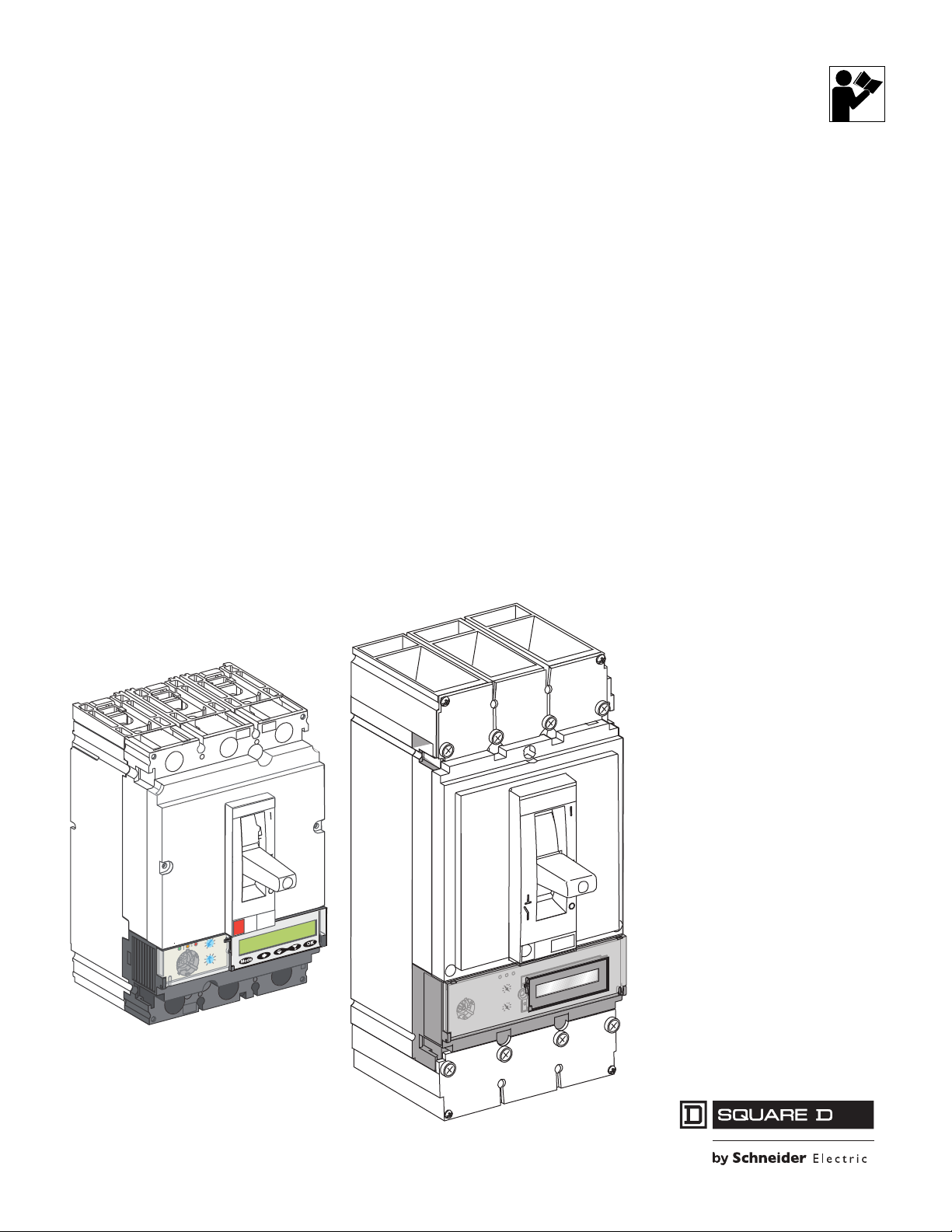
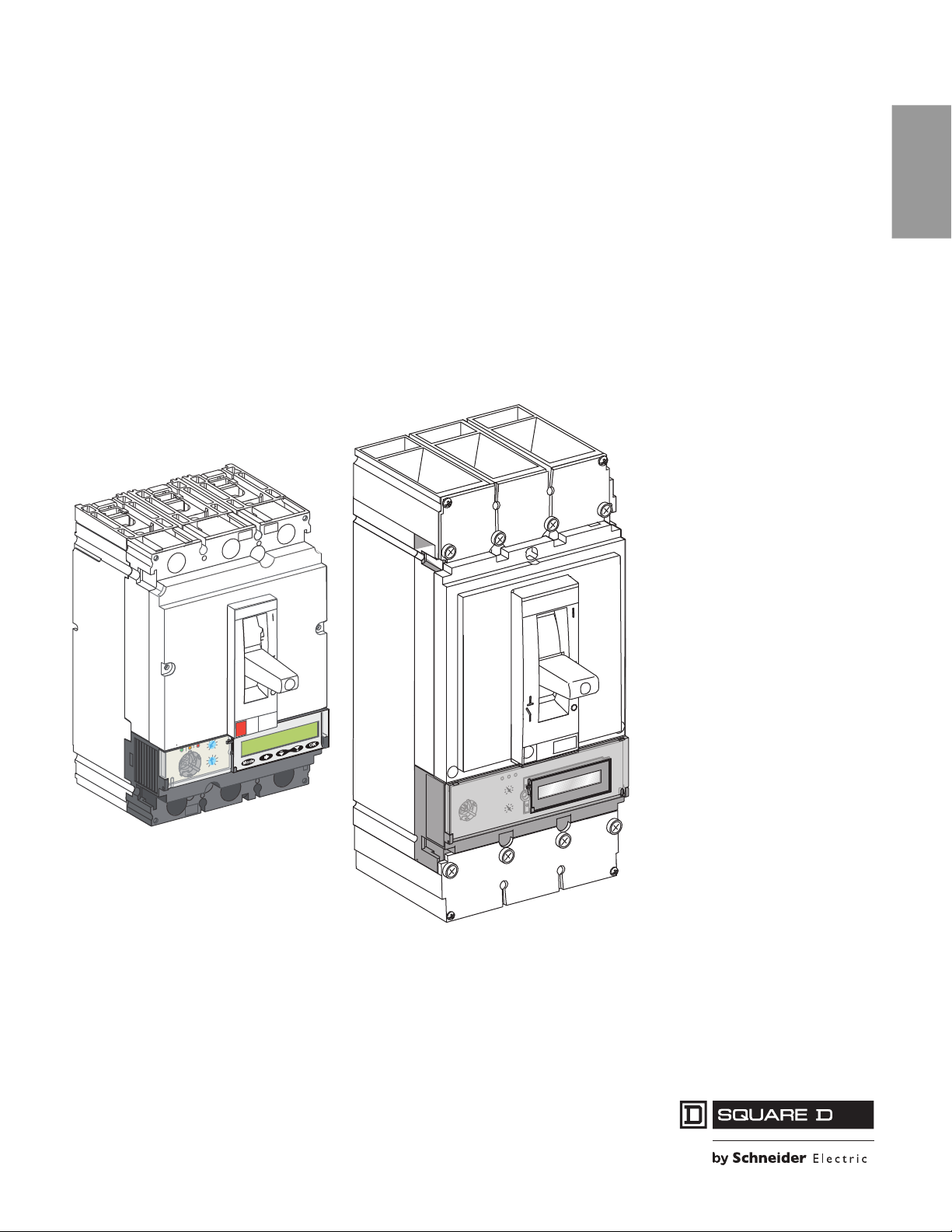
Introduction
MicroLogic 5 and 6 electronic trip units provide:
• Adjustable tripping functions on electronic trip circuit breakers
• Protection for the electrical distribution system or specific applications
• Metering of instantaneous and demand values
• Kilowatt-hour metering
• Operating information (such as peak demand values, customized alarms, or
operation counters)
• Communication
ENGLISH
MicroLogic 5.2 A trip unit
Front faces of MicroLogic trip unit
The product name specifies the protection provided by the trip unit.
MicroLogic 6.2 A-W
Type of Protection
0—Molded case switch (L-frame circuit breaker only)
1—Magnetic only motor circuit protection (L-frame circuit breaker only)
2—Standard motor circuit protection
3—Standard UL protection (LI or LSI), no display
5—Selective protection (LSI), with display
6—Selective protection plus ground-fault protection for equipment (LSIG), with display
Frame Size
2—150/250 A
3—400/600 A
Type of Measurement
A—Provides protection plus ammeter measurements
E—Provides protection plus energy measurements
S—Provides LSI protection with fixed long time delay and fixed short time delay
W—Mission Critical (Selective)
© 2011–2020 Schneider Electric All Rights Reserved48940-312-01
7-EN
Page 10

MicroLogic™ 5 and 6 Electronic Trip Units—User Guide Section 1—General Information
I
s
d(
x
I
r)
8
6
2
3
4
5
7
1
01
.
5
Micrologic
5.2E
A
I
r tr
I
sd ts
d
l
i
(x
l
n
)
N
1
/
A
2
/
B
3
/
C
OK
M
ode
30
Ready
>
1
5
A
Alarm
%
I
r
>9
0
>
1
0
5
36
2
8
1
8
2
0
2
3
2
5
3
2
4
0
I
r
(
A
)
Mic
I
s
d(
x
1
.
5
0
1
2
3
4
5
9
8
7
6
0
1
2
3
4
5
9
8
7
6
3.
2
Micr
o
lo
g
ic
5.1
2
5
.2
3
4
0
1
8
6
5
.9
2
9
.
3
9
.
4
9
.
5
9
.
1
89
.
7
9
.
69
.
0
0
1
0
1
1
5
2
1
0
4
1
0
6
1
0
5
2
52
2
0
02
5
7
1
I
r
d
s
I
dsI
)
r
I
x
(
I
r
)
o
I
x(
o
I
)
A
(
r
I
%
A
0
3
>
0
3>
0
1
1
>
In=250A
MicroLogic trip units can be configured to communicate with other devices. For
ENGLISH
information on the UTA Tester and Modbus™ Interface Module (IFM), see the
product catalog and the circuit breaker user guide.
Modbus™ Interface
Module (IFM)
UTA Tester
Front Display Module
(FDM121)
PowerPact™ H-frame
circuit breaker equipped
with a MicroLogic trip unit,
BSCM, and NSX Cord
For complete information on available circuit breaker models, frame sizes,
interrupting ratings, and trip units, see the product catalog.
This manual describes operation of the MicroLogic 5 and 6 trip units.
In Rating
For additional information see the following user guides available on the Schneider
Electric™ website:
• Bulletin 48940-310-01: MicroLogic™ 1, 2, and 3 Electronic Trip Units—User
Guide.
• Bulletin DOCA0088EN: FDM121—Display for LV Circuit Breaker —User Guide
• Bulletin DOCA0037EN: FDM128—Display For 8 LV Devices—User Guide
To access the website go to:
http://www.schneider-electric.com
For application assistance, please call 1-888-778-2733.
The trip unit In value (A) is visible on the front face of the circuit breaker when the
trip unit is installed. The trip unit In rating (in amperes) is the trip unit maximum
value.
A
For MCP versions, the Full Load Amp (FLA) range is displayed
Example:
250 A trip unit
• Sensor rating I
8-EN
© 2011–2020 Schneider Electric All Rights Reserved 48940-312-01
= 250 A
n
Page 11

Section 1—General Information MicroLogic™ 5 and 6 Electronic Trip Units—User Guide
Control Power
The current through the circuit breaker provides power to operate the MicroLogic trip
unit, maintaining protection if the trip unit is not externally powered.
Backlighting
An optional external 24 Vdc power supply for the MicroLogic trip unit is available
for:
• Modifying the setting values when the circuit breaker is open
• Displaying measurements when the circuit breaker is closed but current
through the circuit breaker is low (15–50 A depending on the rating
• Continuing to display the reason for the trip and the breaking current when the
circuit breaker is open
Without the optional external 24 Vdc power supply, the MicroLogic trip unit only
functions when the circuit breaker is closed. When the circuit breaker is open or the
current through the circuit breaker is low, the MicroLogic trip unit has no power and
the display switches off.
The external 24 Vdc power supply is available to the trip unit when it is connected
to another module in the ULP system (Modbus Interface Module (IFM), Front
Display Module (FDM121), or UTA Tester).
When the MicroLogic trip unit is not connected to a ULP module, it can be
connected directly to an external 24 Vdc power supply using the optional 24 Vdc
supply terminal block.
When the MicroLogic trip unit is powered by an external 24 Vdc power supply, the
trip unit display has white backlighting that is:
ENGLISH
Trip Unit Installation
• Low intensity continuously
• High intensity for 1 minute after pressing one of the keypad buttons
The display backlighting is:
• Deactivated if the temperature exceeds 149°F (65°C)
• Reactivated once the temperature drops back below 140°F (60°C)
On trip units powered by the pocket tester, the display unit is not backlit.
The trip unit is designed for ease of field installation and replacement (for circuit
breakers which offer this capability):
• No connections to make
• Installable with a standard Torx T25 driver
• A mechanical cap ensures trip unit compatibility
• Torque limiting screws ensure secure mounting
© 2011–2020 Schneider Electric All Rights Reserved48940-312-01
9-EN
Page 12

MicroLogic™ 5 and 6 Electronic Trip Units—User Guide Section 1—General Information
ENGLISH
For installation information, see the instruction bulletin shipped with the FieldInstallable Trip Unit (FITU).
NOTE: After installation, the screw heads are accessible so the trip unit can be
removed if necessary.
Trip Unit Sealing
The transparent cover on MicroLogic trip units is sealable.
• A sealed cover prevents modification of the protection settings.
• A sealed cover prevents access to the test port.
• The protection settings and measurements can still be read on the keypad.
10-EN
© 2011–2020 Schneider Electric All Rights Reserved 48940-312-01
Page 13

Section 1—General Information MicroLogic™ 5 and 6 Electronic Trip Units—User Guide
Ii (x In)
35
15
2
3
4
8
6
10
12
15
20
25
30 40
45
50
60
1.5
225
200
175
5
4
3
2
1.5
6
8
10
12
250
Ir (A)
125
150
100
80
70
Ii (x In)
Micrologic
5.2 A
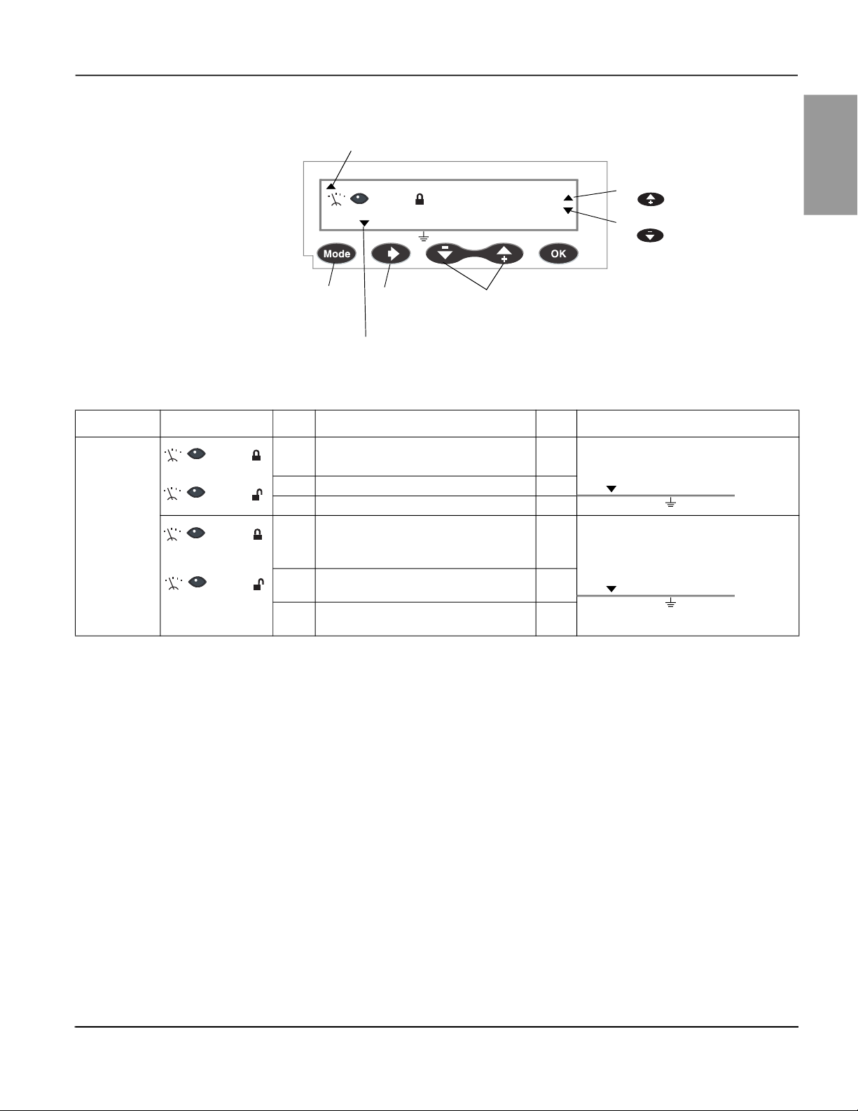
MicroLogic Trip Unit Layout
Trip Unit Face
Use the display screen and keypad on the trip unit to set the trip unit options and
check system measurements. See “Navigation Principles” on page 13 for more
information.
ENGLISH
A
B
C
D
E
A. Indication LEDs: • shows the trip unit operational state
• vary in meaning depending on the trip unit type.
1. Ready LED (green): Blinks slowly when the electronic trip unit is ready to provide protection.
2. Overload pre-alarm LED (orange): Lights when the load exceeds 90% of the I
3. Overload alarm LED (red): Lights when the load exceeds 105% of the I
1
2
3
B. Test Port
Use the test port for:
— connecting a pocket tester for local testing of the MicroLogic trip unit
— connecting the UTA tester for testing, setting the MicroLogic trip unit, and
for installation diagnostics.
C. Dials and Microswitch
A. Indication LEDs
B. Test port
C. Dials for presetting protection
functions and microswitch for locking
protection setting
D. LCD display
E. Navigation keypad
setting.
r
setting.
r
A
B
A. Pickup (Ir) preset dial (distribution trip unit only)
Sets the maximum continuous current level of the circuit breaker. If current exceeds this value, circuit
breaker trips after the preset time delay.
B. Instantaneous (I
) preset dial (distribution trip unit only)
i
Sets the instantaneous trip pickup value setting for the phases and for the neutral (trip unit with
ENCT option and neutral protection active).
C. Microswitch to lock/unlock the protection settings
C
The trip unit face has two dials for presetting protection functions and a microswitch
for locking/unlocking the protection settings. For distribution trip units, the dials are
for setting long-time and instantaneous protection.
Long-time protection:
• protects equipment against overloads
• is standard on distribution trip units
• uses true rms measurement
Instantaneous protection:
• protects equipment against fault currents
• is standard on distribution trip units
© 2011–2020 Schneider Electric All Rights Reserved48940-312-01
11-EN
Page 14

MicroLogic™ 5 and 6 Electronic Trip Units—User Guide Section 1—General Information
OK
• has pickup value setting for the phases and for the neutral (trip unit with ENCT
ENGLISH
option and neutral protection active)
• uses true rms measurement
Trip units are shipped with the long-time pickup switch set at the maximum setting
and all other trip unit switches set at their lowest settings. All advanced protection
settings are turned “off.”
D. LCD display
1. Five pictograms: Metering, Readout, Protection, Setting, Lock.
How pictograms are combined defines the mode
2. Up arrow points to protection function currently being set
3. List of protection functions according to the MicroLogic trip unit type
4. Value of the measured quantity
5. Unit of the measured quantity
6. Navigation arrows
7. Down arrow(s) point to the selected phase(s), neutral, or the ground
8. Phases (1/A, 2/B, 3/C), neutral (N) and ground
An LCD display provides information necessary to use the trip unit. The list of
protection functions varies according to the MicroLogic trip unit type.
On MicroLogic trip units powered by an external 24 Vdc power supply, the trip unit
display has white backlighting that is:
• low intensity continuously
• high intensity for 1 minute after pressing any of the keys on the keypad
• deactivated if the temperature exceeds 149°F (65°C)
• reactivated once the temperature drops back below 140°F (60°C)
NOTE: On trip units powered by the pocket tester, the display unit is not backlit.
E. Navigation keypad Use the 5-button keypad for navigation.
Button Description
Mode
Mode: Selecting the mode
Scroll: Scrolling navigation
Back: Navigation back (metering) or - (setting the protection functions)
Forward: Navigation forward (metering) or + (setting the protection functions)
OK: Confirmation
Screensaver The screensaver displays the instantaneous current passing through the most
heavily loaded phase (Instantaneous measurement readout mode).
The MicroLogic display automatically reverts to a screensaver:
12-EN
• In padlock locked mode, 20 seconds after the last action on the keypad
• In padlock unlocked mode, 5 minutes after the last action on the keypad or
dials
© 2011–2020 Schneider Electric All Rights Reserved 48940-312-01
Page 15
Section 1—General Information MicroLogic™ 5 and 6 Electronic Trip Units—User Guide
Navigation Principles
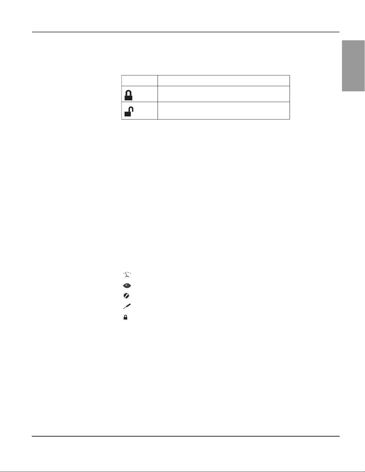
Lock/Unlock the Settings
Table 1 – Protection Settings
Display Description
Padlock locked. The protection settings are locked.
Padlock unlocked. The protection settings are unlocked.
The protection settings are locked when the transparent cover is closed and sealed
to prevent access to the adjustment dials and the locking/unlocking microswitch.
A pictogram on the display indicates whether the protection settings are locked:
To unlock the protection settings:
1. Open the transparent cover
2. Press the lock/unlock microswitch or turn either adjustment dial
To lock the protection settings, press the lock/unlock microswitch again.
The protection settings also lock automatically five minutes after pressing a button
on the keypad or turning one of the dials on the MicroLogic trip unit.
ENGLISH
Trip Unit Modes
Information displays on the MicroLogic trip unit are based on its mode. The modes
available depend on:
• Whether the settings are locked
• The trip unit version
A combination of pictograms define the mode:
Metering
Readout
Protection
Setting
Lock
© 2011–2020 Schneider Electric All Rights Reserved48940-312-01
13-EN
Page 16

MicroLogic™ 5 and 6 Electronic Trip Units—User Guide Section 1—General Information
Table 2 – Possible Modes
ENGLISH
Pictograms Mode Accessible
• Instantaneous measurement readout
or
• Kilowatt hour meter readout and reset
Mode Selection
Readout Mode
Max Reset? OK
or
Max Reset? OK
Select mode by successive presses on the button:
Peak demand readout and reset
Protection function readout
Protection function setting
Neutral status readout
Neutral status setting
Mode
• The modes scroll cyclically.
• Press the lock/unlock microswitch to switch between readout mode and setting
mode.
NOTE: When the Readout icon is visible, protection settings cannot be
altered.
Press the button successively to scroll through the metering screens.
Mode
Scrolling is cyclical.
14-EN
Use the , and navigation buttons to select the metering screen for
each of the phases:
The down indication arrow indicates the phase relating to the measurement value
displayed.
N 1/A 2/B 3/
Indicating arrows on two phases indicates that phase-to-phase value is being
measured:
N 1/A 2/B 3/
Indicating arrows on three phases indicates total power is being measured:
N 1/A 2/B 3/
© 2011–2020 Schneider Electric All Rights Reserved 48940-312-01
Page 17
Section 1—General Information MicroLogic™ 5 and 6 Electronic Trip Units—User Guide
Figure 1 – Readout Screen
Up arrow indicates
function being measured.
Ir tr Isd tsd Ii (x
A
200
N 1/A 2/B 3/
Possible to press
button
the
Possible to press
button
the
ENGLISH
Use to select
measurement
readout mode
Use to select
phase screen is
measuring
Down arrow indicates phase
being measured.
Use to select
measurement to display
Table 3 – Metering Screens
Trip Unit Mode Order Screen Description Unit Arrows
MicroLogic A
(Ammeter)
or
Max Reset? OK
or
Max Reset? OK
Readout as instantaneous rms value of the:
1
• Three phase currents I
2 • Ground-fault current (MicroLogic 6) % I
3 • Neutral current IN (with ENCT option) A
Readout and resetting of the:
4
• Maximum I
currents
• Maximum ground-fault current
5
6
(MicroLogic 6 trip unit)
• Maximum I
(with ENCT option)
i max
max for the neutral current
N
, IB, and IC A
A
for the three phase
The down arrow indicates the conductor
(phase, neutral, or ground) corresponding
to the value shown.
g
N 1/A 2/B 3/
The down arrow indicates the conductor
A
(phase, neutral, or ground) corresponding
to the value shown.
% I
g
N 1/A 2/B 3/
A
Continued on next page
© 2011–2020 Schneider Electric All Rights Reserved48940-312-01
15-EN
Page 18

MicroLogic™ 5 and 6 Electronic Trip Units—User Guide Section 1—General Information
Table 3 – Metering Screens (continued)
ENGLISH
Trip Unit Mode Order Screen Description Unit Arrows
MicroLogic E
(Energy)
or
Max Reset? OK
or
Max Reset? OK
Readout as instantaneous rms value of the:
1
• Three phase currents A, B, and C A
• Ground-fault current (MicroLogic 6 trip
2
unit)
3 • Neutral current IN (with ENCT option) A
Readout as instantaneous rms value of the:
• Phase-to-phase voltages V
4
VCA
• Phase-to-neutral voltages V
, VBC, and
AB
, VBN,
AN
and VCN (with ENVT option)
5 Readout of the total active power P
Readout of the total apparent power S
6
the three phase conductors.
7 Readout of the total reactive power Q
Readout and resetting of the active energy
8
meter E
Readout and resetting of the apparent
9
energy meter E
Readout and resetting of the reactive
10
energy meter E
p
s
q
kW
tot
in
tot
kvar
tot
The down arrow indicates the conductor
(phase, neutral, or ground) corresponding
to the value shown.
% I
g
N 1/A 2/B 3/
The down arrow indicates the conductor
(phase, neutral, or ground) corresponding
V
to the value shown.
N 1/A 2/B 3/
kVA
kWh,
MWh
kVAh,
MVAh
kvarh,
Mvarh
or
Max Reset? OK
or
Max Reset? OK
11 Readout of the phase rotation —
Readout and resetting of the:
12
• Maximum I
• Maximum ground-fault current
13
14
(MicroLogic 6 trip unit)
• Maximum I
(with ENCT option)
for the 3 phase currents
i max
for the neutral current
N max
% I
Readout and resetting of the:
• Maximum V
15
• Maximum V
phase voltages
for the three phase-to-
ij max
for the three phase-
iN max
to-neutral voltages (with ENVT option)
Readout and resetting of the maximum
16
P
of the active power
max
Readout and resetting of the maximum
17
S
of the apparent power kVA
max
Readout and resetting of the maximum
18
of the reactive power kvar
Q
max
kW
kVA
kvar
A
The down arrow indicates the conductor
(phase, neutral, or ground) corresponding
to the value shown.
g
N 1/A 2/B 3/
A
The down arrows indicate the phases
between which the maximum V
V
N was measured.
N 1/A 2/B 3/
The down arrows indicate the three phase
conductors.
N 1/A 2/B 3/
Continued on next page
L-L or L-
max
16-EN
© 2011–2020 Schneider Electric All Rights Reserved 48940-312-01
Page 19
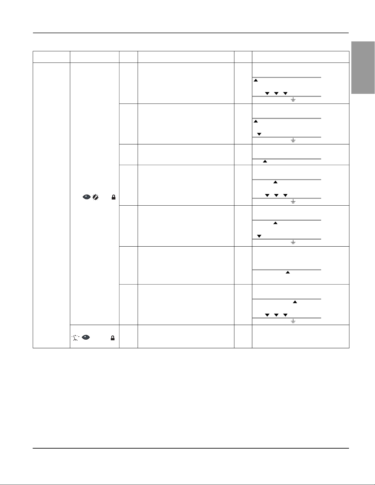
Section 1—General Information MicroLogic™ 5 and 6 Electronic Trip Units—User Guide
Table 3 – Metering Screens (continued)
Trip Unit Mode Order Screen Description Unit Arrows
MicroLogic 5
LSI: Protection
Function
Readout
Screens
I
—Long-time protection pickup value for
r
1
the phases
)—Long-time protection pickup value
I
r(IN
for the neutral (trip unit with ENCT option
2
and neutral protection active)
—Long-time protection time delay value
t
r
4
5
6
)
(at 6 I
r
—Short-time protection pickup value for
I
sd
the phases
) —Short-time protection pickup value
I
sd(IN
for the neutral (trip unit with ENCT option
and neutral protection active)
—Short-time protection time delay value
t
sd
The time delay is for the I2t inverse time
curve protection:
7
• ON: I
• OFF: I
I
setting for the phases and for the neutral
8
(trip unit with ENCT option and neutral
2
t function active
2
t function not active
—Instantaneous protection pickup value
i
protection active).
Neutral status (with ENCT option):
9
• N—Neutral protection active
• noN—Neutral protection not active
The up arrow indicates the I
Ir tr Isd tsd Ii (x In)
A
The down arrows indicate the three phases.
N 1/A 2/B 3/
The up arrow indicates the I
Ir tr Isd tsd Ii (x In)
A
The down arrow indicates the neutral.
N 1/A 2/B 3/
The up arrow indicates the t
s
Ir tr Isd tsd Ii (x In)
The up arrow indicates the I
Ir tr Isd tsd Ii (x In)
A
The down arrows indicate the three phases.
N 1/A 2/B 3/
The up arrow indicates the I
Ir tr Isd tsd Ii (x In)
A
The down arrow indicates the neutral.
N 1/A 2/B 3/
The up arrow indicates the t
s
Ir tr Isd tsd Ii (x In)
The up arrow indicates the I
Ir tr Isd tsd Ii (x In)
A
The down arrows indicate the three phases.
N 1/A 2/B 3/
— —
Continued on next page
function.
r
function.
r
function.
r
function.
sd
function.
sd
function.
sd
function.
i
ENGLISH
© 2011–2020 Schneider Electric All Rights Reserved48940-312-01
17-EN
Page 20

MicroLogic™ 5 and 6 Electronic Trip Units—User Guide Section 1—General Information
Table 3 – Metering Screens (continued)
ENGLISH
Trip Unit Mode Order Screen Description Unit Arrows
function.
r
function.
r
function.
r
sd
sd
sd
function.
g
MicroLogic 6
LSIG:
Protection
Function
Readout
Screens
I
—Long-time protection pickup value for
r
1
the phases
I
)—Long-time protection pickup value
r(IN
2
for the neutral (trip unit with ENCT option
and neutral protection active)
t
—Long-time protection time delay value
r
4
5
6
)
(at 6 I
r
I
—Short-time protection pickup value for
sd
the phases
)—Short-time protection pickup value
I
sd(IN
for the neutral (trip unit with ENCT option
and neutral protection active)
—Short-time protection time delay value
t
sd
The time delay is for the I
curve protection:
7
• ON: I
• OFF: I
I
setting for the phases and for the neutral
8
(trip unit with ENCT option and neutral
2
t function active
2
t function not active
—Instantaneous protection pickup value
i
2
t inverse time
protection active).
9 I
—Ground-fault protection pickup value A A
g
The up arrow indicates the I
Ir tr Isd tsd Ii Ig tg
A
The down arrows indicate the three phases.
N 1/A 2/B 3/
The up arrow indicates the I
Ir tr Isd tsd Ii Ig tg
A
The down arrow indicates the neutral.
N 1/A 2/B 3/
The up arrow indicates the t
s
Ir tr Isd tsd Ii Ig tg
The up arrow indicates the I
Ir tr Isd tsd Ii Ig tg
A
The down arrows indicate the three phases.
N 1/A 2/B 3/
The up arrow indicates the I
Ir tr Isd tsd Ii Ig tg
A
The down arrow indicates the neutral.
N 1/A 2/B 3/
The up arrow indicates the t
s
Ir tr Isd tsd Ii Ig tg
The up arrow indicates the Ii function.
Ir tr Isd tsd Ii Ig tg
A
The down arrows indicate the three phases.
N 1/A 2/B 3/
The up arrow indicates the I
Ir tr Isd tsd Ii Ig tg
The down arrows indicate the three phases.
function.
function.
function.
18-EN
N 1/A 2/B 3/
t
—Ground-fault protection time delay
g
value
The time delay is for the I
10
curve protection:
• ON: I
• OFF: I
2
t function active
2
t function not active
2
t inverse time
The up arrow indicates the t
s
Ir tr Isd tsd Ii Ig tg
function.
g
Neutral status (with ENCT option):
11
• N—Neutral protection active
• noN —Neutral protection not active
— —
© 2011–2020 Schneider Electric All Rights Reserved 48940-312-01
Page 21

Section 1—General Information MicroLogic™ 5 and 6 Electronic Trip Units—User Guide
Energy Meter Readout (MicroLogic E)
Energy meters change measurement unit automatically:
• For active energy, E
, displayed in kWh from 0 to 9999 kWh then in MWh
p
• For reactive energy, Eq, displayed in kvarh from 0 to 9999 kvarh then in Mvarh
• For apparent energy, E
, displayed in kVAh from 0 to 9999 kVAh then in MVAh
s
When energies are in MWh, Mkvarh, or MVAh, the values display on four digits.
The MicroLogic trip unit incorporates the option of full energy meter readout.
NOTE: The energy meter can be reset with the padlock locked or unlocked. Table
4 shows the padlock locked.
Table 4 – Example of Full Energy Readout (MicroLogic E)
Step Readout Value Action Using Display
Reading Full Energy Values
Ir tr Isd tsd Ii (x In)
1
2
Current in most
heavily loaded
phase
Energy
with Reset
option showing
Select the readout and reset the energy meter
mode (main screen displayed).
Select the E
The value displayed is 11.3 MWh (in the
example), which corresponds to 10 MWh +1300
kWh (approximately).
active energy meter.
p
Mode
Ir tr Isd tsd Ii (x In)
N 1/A 2/B 3/
N 1/A 2/B 3/
Reset? OK
229
11.3
ENGLISH
A
MWh
3
4
Specific
energy
measurement
Energy
normal
display
Specify the measurement.
The value displayed is 1130 kW. (In the example
the full energy meter value is 11300 kWh)
Return to the energy meter normal display.
The display reverts automatically after 5
minutes.
Ir tr Isd tsd Ii (x In)
Reset? OK
N 1/A 2/B 3/
Ir tr Isd tsd Ii (x In
Reset? OK
N 1/A 2/B 3/
1130
11.3
Continued on next page
kWh
kWh
© 2011–2020 Schneider Electric All Rights Reserved48940-312-01
19-EN
Page 22

MicroLogic™ 5 and 6 Electronic Trip Units—User Guide Section 1—General Information
Mode
Mode
Table 4 – Example of Full Energy Readout (MicroLogic E) (continued)
ENGLISH
Resetting Full Energy Readout
Ir tr Isd tsd Ii (x In)
Current in most
1
heavily loaded
phase
Energy with
2
Reset option
showing
3 Reset option lit
4 OK
Select the measurement readout and reset
energy meter mode (main screen displayed).
Select the energy meter to reset.
Enter the reset.
The OK pictogram blinks.
Confirm the reset.
The confirmation OK displays for 2 seconds.
N 1/A 2/B 3/
Ir tr Isd tsd Ii (x In)
OK
OK
Reset? OK
N 1/A 2/B 3/
Ir tr Isd tsd Ii (x In)
Reset? OK
N 1/A 2/B 3/
Ir tr Isd tsd Ii (x In)
229
1458
1458
A
kWh
kWh
OK
Resetting Peak Demand Values
1 Main screen
Peak demand
2
with Reset option
showing
3 Reset option lit
4 OK
Select the Readout and reset peak demand
value mode
Select the peak demand to reset.
Enter the reset.
The OK pictogram blinks.
Confirm the reset.
The confirmation OK display for 2 seconds.
N 1/A 2/B 3/
Ir tr Isd tsd Ii (x In)
OK
OK
Max Reset?
N 1/A 2/B 3/
Ir tr Isd tsd Ii (x In)
Max Reset?
N 1/A 2/B 3/
Ir tr Isd tsd Ii (x In)
Reset? OK
N 1/A 2/B 3/
Ir tr Isd tsd Ii (x In)
N 1/A 2/B 3/
243
435
435
A
V
V
OK
20-EN
© 2011–2020 Schneider Electric All Rights Reserved 48940-312-01
Page 23

Section 1—General Information MicroLogic™ 5 and 6 Electronic Trip Units—User Guide
OK
OK
Table 5 – Example of Ground-Fault Protection Readout (MicroLogic 6)
Step Readout Value Action Using Display
Reading Measurement Values
Current in most
1
heavily loaded
phase
2 Ground-fault current
Select the Instantaneous measurement readout
mode (the display is the most heavily loaded
phase, in this example Phase B).
Read the value of current in Phase B.
Select the ground-fault current measurement
screen (the value is a % of the I
Ground-Fault Protection Test (MicroLogic 6)
setting).
g
Mode
Ir tr Isd tsd Ii Ig tg
N 1/A 2/B 3/
Ir tr Isd tsd Ii Ig tg
OK
N 1/A 2/B 3/
A
229
%
17
ENGLISH
Current in most
1
heavily loaded
phase
Peak demand with
2
Reset option
showing
3 Reset option lit
4 OK
Access the ground-fault protection test function by
pressing OK.
The tESt pictogram appears and the OK pictogram
blinks.
Prompt the ground-fault protection test by pressing
OK.
The circuit breaker trips. The ground-fault
protection trip screen is displayed.
Acknowledge the ground-fault trip screen by
pressing OK.
The Reset OK pictogram blinks.
Confirm by pressing OK again
The confirmation OK displays for 2 seconds.
Mode
Ir tr Isd tsd Ii Ig tg
OK
N 1/A 2/B 3/
Ir tr Isd tsd Ii Ig tg
Reset? OK
N 1/A 2/B 3/
Ir tr Isd tsd Ii Ig tg
Reset? OK
N 1/A 2/B 3/
Ir tr Isd tsd Ii Ig tg
N 1/A 2/B 3/
tESt
triP
triP
OK
© 2011–2020 Schneider Electric All Rights Reserved48940-312-01
21-EN
Page 24

MicroLogic™ 5 and 6 Electronic Trip Units—User Guide Section 1—General Information
Mode
Mode
Protection Function Readout
ENGLISH
Select a protection function using the mode key. This selection is only possible in
Readout mode (when the padlock is locked).
• Scrolling is cyclical.
• The up arrow indicates the selected protection function. (For the neutral
protection functions, the down arrow which points to N replaces the up arrow.)
Example: I
Ir tr Isd tsd Ii (x In)
pickup selected
r
Table 6 – Example of Protection Function Readout
Readout
Step
1
2
3
Value
Long-time
protection I
pickup setting
value in
amperes.
Long-time
protection t
time delay
setting value in
seconds.
The short-time
protection I
pickup setting
value in
amperes.
Action Using Display
Select the Protection function readout mode
r
(main screen displayed).
The long-time protection I
in amperes.
r
Select the long-time protection tr time delay.
sd
Select the short-time protection I
pickup setting value
r
pickup
sd
Ir tr Isd tsd Ii (x In)
N 1/A 2/B 3/
Ir tr Isd tsd Ii (x In)
110
A
s
8.0
N 1/A 2/B 3/
Ir tr Isd tsd Ii (x In)
A
715
N 1/A 2/B 3/
Neutral Status Readout Mode
NOTE: The Neutral status readout mode is dedicated to this function. Navigation is
therefore limited to the Mode key.
Table 7 – Example of Neutral Status Readout
Readout
Step
1
22-EN
Value
Neutral status is
displayed
Action Using Display
Select the Neutral status readout mode.
The neutral status value is displayed:
• N—Neutral protection active (with ENCT
option declared)
• noN—Neutral protection not active (without
ENCT option or with ENCT option not
declared)
© 2011–2020 Schneider Electric All Rights Reserved 48940-312-01
Ir tr Isd tsd Ii (x In)
N 1/A 2/B 3/
noN
Page 25

Section 1—General Information MicroLogic™ 5 and 6 Electronic Trip Units—User Guide
CAUTION
Setting Mode
Setting Using a Dial
Figure 2 – Protection
Switches
150
175
125
100
A
80
70
3
B
2
1.5
Ir (A)
4
Ii (x In)
200
5.2 A
225
250
5
6
8
10
12
Micrologic
HAZARD OF NO PROTECTION OR NUISANCE TRIPPING
Modifying the protection functions must be done only by qualified electrical
personnel.
Failure to follow these instructions can result in injury or equipment
damage.
The protection function settings can be set:
• By a dial and fine-tuned on the keypad for the main protection functions
• On the keypad for all protection functions
The up arrow on the display indicates the protection function currently being set.
Use a dial to set (or preset) the Ir (A) and Ii (B) pickups.
Turning a dial results simultaneously in:
• Selection of the screen for the protection function assigned to the dial
• Unlocking (if necessary) the padlock (the navigation interface is in protection
function setting mode)
• Setting the protection function assigned to the dial to the value indicated on the
dial and on-screen.
ENGLISH
Setting Using the Keypad
Use the keypad to fine-tune the protection function.
• The setting value cannot exceed that indicated by the dial.
• All the protection function settings are accessible on the keypad.
Press the button successively to scroll through the protection function
Mode
screens. Scrolling is cyclical.
Navigate through the protection function settings with the , and
navigation buttons.
• Use the button to select the function to set:
— The up arrow indicates the selected function
— The down arrow indicates phase. Multiple down arrows indicate all phases
set to the same value (except for the neutral protection setting)
— Scrolling is cyclical
• Set the protection functions on the keypad with the and buttons.
© 2011–2020 Schneider Electric All Rights Reserved48940-312-01
23-EN
Page 26

MicroLogic™ 5 and 6 Electronic Trip Units—User Guide Section 1—General Information
Figure 3 – Protection Function Screen
ENGLISH
Up arrow indicates
selected function.
Ir tr Isd tsd Ii (x
200
N 1/A 2/B 3/
A
Possible to press
button
the
Possible to press
button
the
Confirmation of Setting
Use to select
protection
function screen
Use to select
function to set
Down arrow
indicates phase.
Use to select
measurement to display
The value of a protection function set on the keypad must be:
1. Entered by pressing the OK key once (the OK pictogram blinks on the display)
2. Then confirmed by pressing the OK key again (the text OK displays for
2 seconds)
NOTE: Setting using a dial does not require any enter/confirm action.
24-EN
© 2011–2020 Schneider Electric All Rights Reserved 48940-312-01
Page 27

Section 1—General Information MicroLogic™ 5 and 6 Electronic Trip Units—User Guide
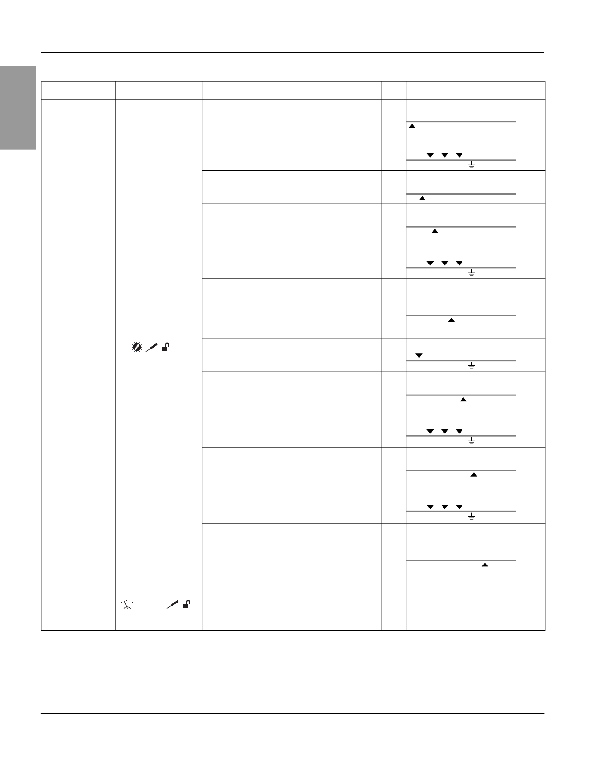
Table 8 – List of Protection Function Setting Screens
Trip Unit Mode Screen Description Unit Arrows
I
—Long-time protection pickup setting for the
r
phases
Preset by a dial
—Long-time protection time delay setting (at 6 Ir) s
t
r
The up arrow indicates the I
Ir tr Isd tsd Ii (x In)
A
The down arrows indicate the three
phases.
N 1/A 2/B 3/
The up arrow indicates the t
Ir tr Isd tsd Ii (x In)
function.
r
function.
r
ENGLISH
MicroLogic 5 LSI
—Short-time protection pickup setting for the
I
sd
phases
Preset by a dial
—Short-time protection time delay setting
t
sd
Activation of the I2t inverse time curve short-time
protection:
2
• ON: I
• OFF: I
I
N
t function active
2
t function not active
—Protection pickup setting for the neutral (trip
unit with ENCT option and neutral protection
active)
—Instantaneous protection pickup value setting
I
i
for the phases and for the neutral (trip unit with
ENCT option and neutral protection active).
Activation of neutral status (trip unit with ENCT
option):
• N: Neutral protection active
• noN: Neutral protection not active
The up arrow indicates the I
Ir tr Isd tsd Ii (x In)
A
The down arrows indicate the three
phases.
N 1/A 2/B 3/
The up arrow indicates the t
s
Ir tr Isd tsd Ii (x In)
The down arrow indicates the neutral.
A
N 1/A 2/B 3/
The up arrow indicates the I
Ir tr Isd tsd Ii (x In)
A
The down arrows indicate the three
phases.
N 1/A 2/B 3/
— —
Continued on next page
function.
sd
function.
sd
function.
i
© 2011–2020 Schneider Electric All Rights Reserved48940-312-01
25-EN
Page 28
MicroLogic™ 5 and 6 Electronic Trip Units—User Guide Section 1—General Information
Table 8 – List of Protection Function Setting Screens (continued)
ENGLISH
Trip Unit Mode Screen Description Unit Arrows
The up arrow indicates the I
—Long-time protection pickup setting for the
I
r
phases
Preset by a dial
t—Long-time protection time delay setting s
Ir tr Isd tsd Ii Ig tg
A
The down arrows indicate the three
phases.
N 1/A 2/B 3/
The up arrow indicates the t
Ir tr Isd tsd Ii Ig tg
function.
r
function.
r
MicroLogic 6 LSIG:
I
—Short-time protection pickup setting for the
sd
phases
—Short-time protection time delay setting
t
sd
The time delay is for the I
2
t inverse time curve
protection:
2
• ON: I
• OFF: I
I
N
t function active
2
t function not active
—Protection pickup setting for the neutral (trip
unit with ENCT option and neutral protection
active)
—Instantaneous protection pickup setting for the
I
i
phases and for the neutral (trip unit with ENCT
option and neutral protection active).
I—Ground-fault protection pickup setting
Preset by a dial
The up arrow indicates the I
Ir tr Isd tsd Ii Ig tg
A
The down arrows indicate the three
phases.
N 1/A 2/B 3/
The up arrow indicates the t
s
Ir tr Isd tsd Ii Ig tg
The down arrow indicates the neutral.
A
N 1/A 2/B 3/
The up arrow indicates the I
Ir tr Isd tsd Ii Ig tg
A
The down arrows indicate the three
phases.
N 1/A 2/B 3/
The up arrow indicates the Ig function.
Ir tr Isd tsd Ii Ig tg
A
The down arrows indicate the three
phases.
function.
sd
function.
sd
function.
i
26-EN
N 1/A 2/B 3/
t
—Ground-fault protection time delay setting
g
The time delay is for the I2t inverse time curve
protection:
2
• ON: I
• OFF: I
t function active
2
t function not active
The up arrow indicates the t
s
Ir tr Isd tsd Ii Ig tg
function.
g
Activation of neutral status (trip unit with ENCT
option):
• N—Neutral protection active
• noN—Neutral protection not active
— —
© 2011–2020 Schneider Electric All Rights Reserved 48940-312-01
Page 29

Section 1—General Information MicroLogic™ 5 and 6 Electronic Trip Units—User Guide
Presetting a Protection Function
Table 9 illustrates presetting and setting the long-time protection Ir pickup on a
MicroLogic trip unit 5.2 rated 250 A:
Press the button to scroll through the metering screens.
Mode
Press the , and navigation buttons to select the metering screen for
each of the phases:
Table 9 – Example of Presetting a Protection Function Using a Dial
Step Action Using Display
Set the Ir dial to the maximum value (the padlock unlocks
1
2
4
automatically).
The down arrows indicate all 3 phases (the setting is identical
on each phase).
Turn the I
Presetting is complete:
• If the pickup setting value is correct (in this case, 175 A), exit
• If the pickup setting value is not suitable, fine-tune it on the
Set the exact value required for I
(in increments of 1 A).
dial to the setting above the value required.
r
the setting procedure (no enter keystroke is required).
keypad.
on the keypad
r
16
17
14
10
14
10
Ir (A)
16
Ir (A)
25
17
25
20
22
20
22
12
11
12
11
Ir tr Isd tsd Ii (x In)
N 1/A 2/B 3/
Ir tr Isd tsd Ii (x In)
N 1/A 2/B 3/
Ir tr Isd tsd Ii (x In)
N 1/A 2/B 3/
OK
ENGLISH
A
250
A
175
A
170
Ir tr Isd tsd Ii (x In)
5
6
Enter the reset.
The OK pictogram blinks.
Confirm the reset.
The confirmation OK displays for 2 seconds.
OK
OK
OK
N 1/A 2/B 3/
Ir tr Isd tsd Ii (x In)
N 1/A 2/B 3/
170
A
OK
© 2011–2020 Schneider Electric All Rights Reserved48940-312-01
27-EN
Page 30

MicroLogic™ 5 and 6 Electronic Trip Units—User Guide Section 1—General Information
Mode
Setting a Protection Function
ENGLISH
Table 10 illustrates setting the long-time protection tr time delay on a MicroLogic
5.2 trip unit:
Press the button to scroll through the screens.
Mode
Press the , and navigation buttons to select the screen for each of
the phases:
Table 10 – Example of Setting a Protection Function Using the Keypad
Step Action Using Display
Ir tr Isd tsd Ii Ig tg
1
2 Select the protection function setting mode.
3 Select the t
If the locked pictogram is displayed, unlock the
protection settings.
function: the up arrow moves under tr.
r
N 1/A 2/B 3/
Ir tr Isd tsd Ii (x In)
N 1/A 2/B 3/
Ir tr Isd tsd Ii (x In)
N 1/A 2/B 3/
A
229
A
170
s
0.5
4 Set the t
5 Enter the setting (the OK pictogram blinks).
6
Confirm the setting.
The confirmation OK displays for 2 seconds.
value required on the keypad.
r
Ir tr Isd tsd Ii (x In)
s
OK
N 1/A 2/B 3/
Ir tr Isd tsd Ii (x In)
OK
OK
OK
N 1/A 2/B 3/
Ir tr Isd tsd Ii (x In)
N 1/A 2/B 3/
8.0
s
8.0
OK
28-EN
© 2011–2020 Schneider Electric All Rights Reserved 48940-312-01
Page 31

Section 2—Electrical Distribution Protection MicroLogic™ 5 and 6 Electronic Trip Units—User Guide
1
5
4
3
2
7
6
10
9
8
In=400A
Section 2— Electrical Distribution Protection
MicroLogic 5 and 6 trip units provide protection against overcurrents and groundfault currents for commercial or industrial applications.
When choosing the protection characteristics to use, take account of:
• Overcurrents (overloads and short-circuits) and potential ground-fault currents
• Conductors than need protection
• The presence of harmonic currents
• Coordination between the devices
• Mission Critical trip units with enhanced selectivity have a “W” in the trip unit
number (for example, 3.2W or 3.2S-W)
Protection Functions
Functions are reviewed in detail on the following pages.
Table 11 – Protective Functions Trip Curve
Protective Functions Trip Curve No Function Description
1 I
n
2 I
r
3 t
r
4 I
sd
5 t
sd
2
6 I
t ON/OFF Short-time protection I2t curve in ON or OFF position A A
7 I
i
8 I
g
9 t
g
2
10 I
t ON/OFF
Sensor rating N N
Long-time protection pickup A A
Long-time protection time delay A A
Short-time protection pickup A A
Short-time protection time delay A A
Instantaneous protection pickup A A
Ground-fault protection pickup — A
Ground-fault protection time delay — A
Ground-fault protection I2t curve in ON or OFF
position
ENGLISH
MicroLogic Trip Unit
5 6
— A
A = Adjustable
N = Not Adjustable
— = Not Available
Setting the Protection
Reflex Tripping
To set the protection functions:
• On the MicroLogic trip unit, use the preset dials (depending on the protection
function and the MicroLogic type) and the keypad.
• With the communication option, use the RSU software under the Basic
protection tab.
For more information about using the RSU software to set the protection function,
see “Setting the Protection Functions” on page 81.
In addition to the devices integrated in the MicroLogic trip units, the PowerPact™ Lframe circuit breakers have reflex protection. This system breaks very high fault
currents by mechanically tripping the device with a “piston” actuated directly by the
pressure produced in the circuit breaker from a short circuit. This piston operates
the opening mechanism, resulting in ultra-fast circuit breaker tripping.
© 2011–2020 Schneider Electric All Rights Reserved48940-312-01
29-EN
Page 32

MicroLogic™ 5 and 6 Electronic Trip Units—User Guide Section 2—Electrical Distribution Protection
Selective Coordination
ENGLISH
Figure 4 – Coordination Trip Curves
Q
Q
2
1
Q
1
Q
2
Selective coordination between the upstream and downstream devices is essential
to optimize continuity of service. The large number of options for setting the
protection functions on MicroLogic 5 and 6 trip units improves the natural
coordination between circuit breakers.
Schneider Electric provides trip curves for each circuit breaker and tables showing
UL Listed series-rated circuit breakers. Trip curves can be found on our website:
http://www.schneider-electric.us
In the search box, type “PowerPact H, J, L”. Click on “PowerPact H/J/L Frame
Molded Case Circuit Breakers”, then click on the “Documents and Downloads” tab.
The user guides and trip curves are found within this tab.
For assistance, please call 1-888-778-2733.
Mission Critical Circuit Breakers
The PowerPact J- and L-Frame Mission Critical circuit breakers deliver high levels
of selective coordination with the QO™ family of miniature circuit breakers and the
ED, EG, and EJ circuit breakers in a flexible design that can be easily configured
for a variety of applications. These circuit breaker can be equipped with 5.2A-W,
5.2E-W, 6.2A-W, 5.3A-W, 6.3A-2, and 6.3E-2 MicroLogic trip units.
The mission critical trip units have the same settings and trip curves as the
standard trip units as described in this document.
For more information see catalog 0611CT1001 PowerPact H-, J-, and L-Frame
Circuit Breakers on the Schneider Electric website.
30-EN
© 2011–2020 Schneider Electric All Rights Reserved 48940-312-01
Page 33

Section 2—Electrical Distribution Protection MicroLogic™ 5 and 6 Electronic Trip Units—User Guide
Tripping curve:
In
I
r
t
r
In=250A
t
r
I
r
6 I
r
Long-Time Protection
Figure 5 – Long-Time Protection Curve
In = Trip unit setting range: Minimum setting/maximum setting - trip unit
rating
I
n
Ir = Long-time protection pickup
= Long-time protection time delay
t
r
Long-time protection on MicroLogic 5 and 6 trip units protect electrical distribution
applications against overload currents. It is identical for MicroLogic 5 and 6 trip units.
2
Long-time protection is I
t IDMT (Inverse Definite Minimum Time):
ENGLISH
• It incorporates the thermal image function.
• It is set with the I
Setting the Long-Time Protection
Set the Ir pickup:
• Using the MicroLogic trip unit I
tune the value
• With the communication option, preset using the I
unit and fine-tune the setting using the RSU software
Set the time delay t
• Using the keypad on the MicroLogic trip unit
• With the communication option, set using the RSU software
Ir Pickup Setting Values
The long-time protection tripping range is 1.05–1.20 Ir.
The default Ir pickup setting value is the maximum dial position In.
Use the keypad to fine-tune the setting, in increments of 1 A:
• The setting range maximum is the preset value of the dial.
• The range minimum is the minimum preset value (for the 400 A rating, the
setting range minimum is 125 A).
Example:
A MicroLogic 5.2 trip unit rated I
• The minimum preset value is 70 A
• The keypad fine-tuning range is 70–150 A
pickup and the tr trip time delay.
r
dial to preset the value and the keypad to fine-
r
:
r
= 250 A is preset using the dial at 150 A:
n
dial on the MicroLogic trip
r
© 2011–2020 Schneider Electric All Rights Reserved48940-312-01
31-EN
Page 34

MicroLogic™ 5 and 6 Electronic Trip Units—User Guide Section 2—Electrical Distribution Protection
2
5
3
2
5
A
B
11
4
The setting value displayed is the value of the trip time delay for a current of 6 Ir.
ENGLISH
Table 12 – Preset Values of I
(A)
r
In Rating
60 A 15 A 20 A 25 A 30 A 35 A 40 A 45 A 50 A 60 A
100 A 35 A 40 A 45 A 50 A 60 A 70 A 80 A 90 A 100 A
150 A 50 A 60 A 70 A 80 A 90 A 100 A 110 A 125 A 150 A
250 A 70 A 80 A 100 A 125 A 150 A 175 A 200 A 225 A 250 A
400 A 125 A 150 A 175 A 200 A 225 A 250 A 300 A 350 A 400 A
600 A 200 A 225 A 250 A 300 A 350 A 400 A 450A 500 A 600 A
tr Time Delay Setting Values
The default tr time delay setting value is 0.5 (minimum value) that is, 0.5 seconds at
6 I
Table 13 shows the value of the trip time delay (in seconds) according to the
current in the load for the setting values displayed on-screen.
The accuracy range is -20%/+0%.
Table 13 – Preset Values of tr (seconds)
Current in the
Load
1.5 t
6 t
7.2 t
Preset Values of I
Depending on the Trip Unit In Rating and the Dial
r
Position
.
r
Setting Value
0.5 1 2 4 8 16
t
Trip Time Delay
r
r
r
r
15 s 25 s 50 s 100 s 200 s 400 s
0.5 s 1 s 2 s 4 s 8 s 16 s
0.35 s 0.7 s 1.4 s 2.8 s 5.5 s 11 s
Thermal Image
The trip unit uses the calculation of a thermal image to evaluate the conductor heat
rise and precisely monitor the thermal state of the conductors.
Example:
Comparison of the heat rise calculation without thermal image (diagram A) and with
thermal image (diagram B):
• Trip unit without thermal image: On each current pulse, the trip unit only
considers the thermal effect on the pulse under consideration. No tripping
occurs despite the build-up in conductor heat rise.
• Trip unit with thermal image: The trip unit adds the thermal effect of successive
current pulses. Tripping occurs based on the actual thermal state of the conductor.
Figure 6 – Conductor Heat Rise Diagrams
32-EN
Diagram A
© 2011–2020 Schneider Electric All Rights Reserved 48940-312-01
Diagram B
1. Instantaneous current (cyclical) in the load
2. Conductor temperature
3. Current calculated without thermal image
(diagram A)
4. Current calculated with thermal image
(diagram B)
5. Long-time protection pickup: I
r
Page 35

Section 2—Electrical Distribution Protection MicroLogic™ 5 and 6 Electronic Trip Units—User Guide
I
r
t
sd
I
sd
t
sd
I
sd
Conductor Heat Rise and Tripping Curves
Figure 7 – Heat Rise Curve
A. Heat rise curve for an equilibrium temperature
B. Trip curve or the limit temperature
1. Low intensity current zone
2. Low overcurrent zone
Use the analysis of the equation of heat rise in a conductor, through which a
current I runs, to determine the nature of physical phenomena:
ENGLISH
Thermal Memory
Short-Time Protection
• For low- or medium-intensity currents (I < I
), the conductor equilibrium
r
temperature (for an infinite time) only depends on the current quadratic
demand value, see “Quadratic Demand Value (Thermal Image)” on page 48.
The limit temperature corresponds to a limit current (I
pickup for trip unit long-
r
time protection).
• For low overcurrents (I
< I < Isd), the conductor temperature only depends on
r
the I2t energy provided by the current. The limit temperature is an I2t IDMT
curve.
• For high overcurrents (I > I
), the phenomenon is identical if the I2t ON
sd
function of the short-time protection has been configured, see “I2t ON/OFF
Function” on page 37.
MicroLogic 5 and 6 trip units incorporate the thermal memory function which
ensures that the conductors are cooled even after tripping. Cooling lasts for 20
minutes before or after tripping.
Figure 8 – Short-Time Protection Tripping Curve
Ir = Long-time protection pickup
= Short-time protection pickup
I
sd
= Short-time protection time delay
t
sd
I2t = Inverse time curve function (ON or OFF)
Short-time protection on MicroLogic 5 and 6 trip units protects all types of electrical
distribution applications against short-circuit currents.
© 2011–2020 Schneider Electric All Rights Reserved48940-312-01
33-EN
Page 36

MicroLogic™ 5 and 6 Electronic Trip Units—User Guide Section 2—Electrical Distribution Protection
It is identical for MicroLogic 5 and 6 trip units.
ENGLISH
Short-time protection is definite time:
• It incorporates the possibility of an I
• It is set using the I
pickup and the tsd trip time delay
sd
2
t inverse time curve function
Setting the Short-Time Protection
Set the Isd pickup:
• Using the keypad on the MicroLogic trip unit.
• With the communication option, set using the RSU software.
Set the t
• Using the keypad on the MicroLogic trip unit.
• With the communication option, set using the RSU software.
The t
Isd Pickup Setting Values
The Isd pickup setting value is in multiples of Ir.
The default Isd pickup setting value is 1.5 Ir (minimum dial value).
Table 14 shows the setting values (preset by a dial) and setting ranges (set on the
keypad) of the I
Table 14 – Preset Values of I
Type of Setting Value or Setting Range (x Ir)
Preset by a dial
(MicroLogic 5)
Setting range on the keypad
Increment: 0.5 I
1
The accuracy range is +/- 10%.
2
For MicroLogic 6 trip units, the setting range value on the keypad is: 1.5–10 Ir.
tsd Time Delay Setting Values
time delay:
sd
time delay setting includes activation/deactivation of the I2t option.
sd
pickup.
sd
(A)
sd
1
1.5 2 3 4 5 6 8 10 12
1
r
1.5 1.5–2 1.5–3 1.5–4 1.5–5 1.5–6 1.5–8 1.5–10 1.5–12
I2t ON/OFF
34-EN
Table 15 indicates the setting values for the tsd time delay with the I2t OFF/ON
option in seconds (s) and the associated hold and breaking times in milliseconds
(ms).
The default t
time delay setting value is 0 seconds with I2t OFF.
sd
Table 15 – Preset Values of tsd
Function Setting Value
tsd with I2t OFF 0 0.1 s 0.2 s 0.3 s 0.4 s
t
with I2t ON — 0.1 s 0.2 s 0.3 s 0.4 s
sd
Hold Time 20 ms 80 ms 140 ms 230 ms 350 ms
Maximum Breaking Time 80 ms 140 ms 200 ms 320 ms 500 ms
Use the I2t inverse time curve function to improve circuit breaker coordination. Use
it when a protection device using inverse time only is installed downstream, for
example a fuse protection device.
© 2011–2020 Schneider Electric All Rights Reserved 48940-312-01
Page 37

Section 2—Electrical Distribution Protection MicroLogic™ 5 and 6 Electronic Trip Units—User Guide
I2t OFF I
2
t ON
t(s)
RK5-200 A
L-Frame Circuit Breaker
MicroLogic 5.3 A - 600 A
I (A)
t(s)
RK5-200 A
I (A)
L-Frame Circuit Breaker
MicroLogic 5.3 A - 600 A
The curves illustrate an example of selective coordination between a PowerPact™
L-frame circuit breaker upstream, and a RK5-200 A fuse downstream.
2
Use the I
t ON function on the short-time protection to provide coordination.
Figure 9 – Example of Coordination
Instantaneous Protection
Figure 10 – Instantaneous Protection Curve
ENGLISH
Setting the Instantaneous Protection
I
In=250A
n
In = Trip unit setting range: Maximum setting = trip unit In rating
= Instantaneous protection pickup
I
i
I
i
I
i
Instantaneous protection on MicroLogic 5 and 6 trip units protects all types of
electrical distribution applications against very high short-circuit currents.
It is identical for MicroLogic 5 and 6 trip units.
Instantaneous protection is definite time, set as I
pickup and without a time delay.
i
Set the Ii pickup:
• Using the MicroLogic trip unit Ii dial to preset the value and the keypad to finetune the value
• With the communication option, preset using the I
unit and fine-tune setting using the RSU software
dial on the MicroLogic trip
i
© 2011–2020 Schneider Electric All Rights Reserved48940-312-01
35-EN
Page 38

MicroLogic™ 5 and 6 Electronic Trip Units—User Guide Section 2—Electrical Distribution Protection
In
t
g
I
g
2
I t
70/250A
I
g
t
g
Ii Pickup Setting Values
ENGLISH
The Ii pickup setting value is in multiples of In.
The default Ii pickup setting value is 1.5 In (minimum value).
Table 16 shows the setting ranges and increments according to the MicroLogic trip
rating.
unit I
n
• The accuracy range is +/- 10%.
• The hold time is 10 milliseconds.
• The maximum breaking time is 50 milliseconds.
Table 16 – Preset Values of I
In Rating Setting Range Increment
60, 100 A and 150 A 1.5–15 I
250 A and 400 A 1.5–12 I
600 A 1.5–11 I
i
n
n
n
0.5 I
0.5 I
0.5 I
n
n
n
Ground-Fault Protection
Figure 11 – Ground-Fault Protection Tripping Curve
Ground-fault protection on MicroLogic 6 trip units protects all types of electrical
distribution applications against ground-fault currents.
For more details on ground-fault currents, see the bulletin shipped with the circuit
breaker
Ground-fault protection is definite time:
• It includes the possibility of an I
• Set as Ig pickup and as tg trip time delay.
Setting the Ground-Fault Protection
Set the Ig pickup:
In = Trip unit setting range: Minimum setting/maximum setting = trip unit In rating
Ig = Ground-fault protection pickup
= Ground-fault protection time delay
t
g
2
t = Ground-fault protection I2t curve in ON or OFF position
I
2
t inverse time curve function
• Using the keypad on the MicroLogic trip unit.
• With the communication option, set using the RSU software.
36-EN
© 2011–2020 Schneider Electric All Rights Reserved 48940-312-01
Page 39

Section 2—Electrical Distribution Protection MicroLogic™ 5 and 6 Electronic Trip Units—User Guide
Set the tg time delay:
• Using the keypad on the MicroLogic trip unit.
• With the communication option, set using the RSU software.
time delay setting incorporates activation/deactivation of the I2t option.
The t
g
Ig Pickup Setting Values
The Ig pickup setting value is in multiples of In.
ENGLISH
The default I
• 0.30 In for trip units rated 60 A
• 0.20 I
Table 17 specifies the setting ranges. The increment is 0.05 In.
Table 17 – I
In = Ig Pickup Setting Values (x In)
60 A 0.3 0.35 0.4 0.45 0.5 0.55 0.6 0.65 0.7 0.75 0.8 0.85 0.9 0.95 1
100–600 A 0.2 2.5 0.3 0.35 0.4 0.45 0.5 0.55 0.6 0.65 0.7 0.75 0.8 0.85 0.9 0.95 1
1
tg Time Delay Setting Values
The tg time delay setting value is in seconds. The hold and breaking times are in
milliseconds.
The default t
Table 18 shows t
hold and breaking times.
Table 18 – Preset Values of t
Function Setting Value
pickup setting value is the same as the minimum value read on the dial:
g
for trip units rated > 60 A
n
Pickup Setting Values
g
The accuracy range is +/- 10%.
time delay setting value is 0 s with I2t OFF.
g
setting values with the I2t OFF/ON option and the associated
g
1
g
tg with I2t OFF 0 s 0.1 s 0.2 s 0.3 s 0.4 s
with I2t ON — 0.1 s 0.2 s 0.3 s 0.4 s
t
g
Hold time 20 ms 80 ms 140 ms 230 ms 350 ms
Maximum breaking time 80 ms 140 ms 200 ms 320 ms 500 ms
I2t ON/OFF Function
Operation of the I2t ON/OFF ground-fault protection is similar to that of the shorttime I2t function (see “Short-Time Protection” on page 33).
Ground-Fault Protection Test
Perform the ground-fault protection test on the keypad of the MicroLogic trip unit
(see “Ground-Fault Protection Test (MicroLogic 6)” on page 21). Use this test to
check the trip unit’s electronic tripping function.
© 2011–2020 Schneider Electric All Rights Reserved48940-312-01
37-EN
Page 40

MicroLogic™ 5 and 6 Electronic Trip Units—User Guide Section 2—Electrical Distribution Protection
Neutral Protection
ENGLISH
Table 19 – Possible Neutral Protection Types
Circuit Breaker Possible Types Neutral Protection
Circuit breaker 3P, 3D None
3P, 3D None
Circuit breaker with ENCT
option
P: Pole; D: Trip unit; N: Neutral protection
3P, 3D + N/2 Half neutral
3P, 3D + N Full neutral
3P, 3D + OSN Oversized neutral
Neutral protection on MicroLogic 5 and 6 trip units protects all types of electrical
distribution applications against overload and short-circuit currents.
It is available on trip units with ENCT option
It is identical for MicroLogic 5 and 6 trip units.
Normally, the phase protection protects the neutral conductor (if it is distributed and
identical to the phases in size, that is, full neutral).
The neutral must have specific protection if:
• It is reduced in size compared to the phases
• Nonlinear loads generating third order harmonics (or multiples thereof) are
installed
Operation
It may be necessary to switch off the neutral for operational reasons (multiple
source diagram) or safety reasons (working with power off).
To summarize, the neutral conductor can be:
• Non-distributed
• Distributed, not switched off, and not protected
• Distributed, not switched off but protected
(circuit breaker with ENCT option)
Figure 12 – Neutral Protection Tripping Curve
I
In=250A
n
In = Trip unit setting range: The maximum
I
r
setting corresponds to the trip unit I
I
i
Ir = long-time protection pickup
= Neutral protection time delay
I
i
rating
n
38-EN
© 2011–2020 Schneider Electric All Rights Reserved 48940-312-01
Page 41

Section 2—Electrical Distribution Protection MicroLogic™ 5 and 6 Electronic Trip Units—User Guide
Neutral protection has the same characteristics as phase protection:
• Its pickup is in proportion with the long-time I
• It has the same trip time delay values as the long-time Ir and short-time Isd
protections.
• Its instantaneous protection is identical.
Setting the Neutral Protection
Set the trip unit Neutral status and the IN pickup:
• Using the keypad on the MicroLogic trip unit
• With the communication option, set using the RSU software
Neutral Protection Setting Value
MicroLogic 5 and 6 trip units incorporate the OSN (Oversized Neutral) function,
which manages protection of the neutral conductor when third-order harmonic
currents (and multiples thereof) are present (see “Harmonic Currents” on page 55).
Table 20 shows, according to the value of the I
the neutral long-time protection and neutral short-time protection pickups:
Table 20 – Values of Neutral Protection Settings0tc
N / Ir Function Long-Time Pickup Value Ir(IN) Short-Time Pickup Value Isd(IN)
OFF N/A N/A
0.5
1 Ir Isd
OSN with ENCT 1.6 x I
and short-time I
r
/ Ir function, the setting values of
N
I
/ 2 I
r
r
protection pickups.
sd
/ 2
sd
1.6 x Isd
ENGLISH
The setting values are identical for the phases, the neutral long-time, and shorttime protection time delays.
Table 21 shows the setting values of the neutral protection pickups (set to OSN)
according to the phase protection pickup I
Table 21 – Setting Values of the Neutral Protection Pickups
I
/ IN Values Long-Time Pickup Value Ir(IN) Short-Time Pickup Value Isd(IN)
r
Ir / IN < 0.63 1.6 x Ir 1.6 x Isd
0.63 < Ir / In < 1 I
Selection of the ENCT Option
Table 22 – The ENCT Option
In Rating Neutral Protection Limited to In OSN Protection > In
1
For the 600 A rating, the OSN function is limited to In (= 600 A).
The ENCT option is an external neutral CT for a trip unit.
setting:
r
N
60 A LV429521 LV429521
100 A LV429521 LV429521
150 A LV430563 LV430563
250 A LV430563 LV432575
400 A LV432575 LV432575
600 A LV432575 No
1
IN x I
/ I
sd
r
© 2011–2020 Schneider Electric All Rights Reserved48940-312-01
39-EN
Page 42

MicroLogic™ 5 and 6 Electronic Trip Units—User Guide Section 2—Electrical Distribution Protection
Table 22 indicates the reference for the ENCT option installed according to the In
ENGLISH
rating of the MicroLogic trip unit or the need for OSN protection:
Installing the ENCT option
1. Connect the neutral conductor to the ENCT option primary (terminals H1, H2).
2. Remove (if existing) the jumper between terminals T1 and T2 of the MicroLogic
trip unit.
3. Connect the ENCT option secondary (terminals T1, T2) to terminals T1 and T2
of the MicroLogic trip unit.
4. Declare the ENCT option when setting the protection functions for the
MicroLogic trip unit.
NOTE: If the ENCT option is declared before its installation, the MicroLogic trip unit
develops a fault (ENCT screen). Either install the ENCT option or to connect a
jumper between terminals T1 and T2 on the MicroLogic trip unit. Clear the ENCT
screen by pressing the OK key two times (enter and confirm).
40-EN
© 2011–2020 Schneider Electric All Rights Reserved 48940-312-01
Page 43

Section 2—Electrical Distribution Protection MicroLogic™ 5 and 6 Electronic Trip Units—User Guide
ZSI 1
ZSI 2
t
sd
Q
1
t
sd
Q
1
Q
2
Q
2
Z1
Z2
Z3
Z4
Z5
Z1
Z2
Z3
Z4
Z5
Z1
Z2
Z3
Z4
Z5
3Q2Q1Q
Zone Selective Interlocking (ZSI)
Use zone selective interlocking (ZSI) to reduce the electrodynamic stress on
equipment when using selective coordination.
Example of ZSI Operation
ZSI improves coordination by being selective about the position of the fault. A
signal wire links the installed circuit breaker trip units and manages the trip time
delay for upstream circuit breakers according to the fault position.
ZSI optimizes the availability of energy and reduce electrodynamic stress on the
equipment. It is applicable to both short-time and ground-fault protection.
Figure 13 – ZSI Example
The trip units on circuit breakers Q1 and Q2 have the same time delay settings as
with selective coordination.
• If a fault occurs downstream of downstream circuit breaker Q2 (Figure 13, ZSI
1), the trip units on circuit breakers Q1 and Q2 detect the fault simultaneously.
The trip unit on circuit breaker Q2 sends a restraint signal to the trip unit on
circuit breaker Q1, which remains set on its time delay t
. Circuit breaker Q2
sd
trips and clears the fault (instantaneously if circuit breaker Q2 is not delayed).
The other users downstream of circuit breaker Q1 still have power, the energy
availability is optimized.
• If a fault occurs downstream of circuit breaker Q1 (Figure 13, ZSI 2), the trip
unit on circuit breaker Q1 does not receive a signal from the trip unit on circuit
breaker Q2. Time delay t
is therefore inhibited. Circuit breaker Q1 trips and
sd
clears the fault on the equipment instantaneously. The electrodynamic stress
created by the short-circuit current on the equipment is reduced to the
minimum.
ENGLISH
ZSI Wiring
The MicroLogic 5 and 6 trip units support ZSI. The signal wire is connected to the
trip unit as shown Figure 14.
Figure 14 – ZSI Wiring
Q1 Upstream circuit breaker
Q2 Circuit breaker being wired
Q3 Downstream circuit breaker
© 2011–2020 Schneider Electric All Rights Reserved48940-312-01
41-EN
Page 44

MicroLogic™ 5 and 6 Electronic Trip Units—User Guide Section 2—Electrical Distribution Protection
Z1
Z2
Z3
Z4
Z5
Z1
Z2
Z3
Z4
Z5
Q1
Q2
Z1 ZSI-OUT source
ENGLISH
Z2 ZSI-OUT
Z3 ZSI-IN source
Z4 ZSI-IN ST short-time protection
Z5 ZSI-IN GF ground-fault protection (MicroLogic 6)
The short-time and ground-fault protection time delay settings (MicroLogic 6) for
trip units using ZSI must comply with the rules relating to selective coordination.
ZSI Connection
Connection Wire Characteristics:
• Impedance: <16 Ω per 300 m
• Maximum length: 300 m
• Type of cable: Shielded twisted (Belden 8441 or equivalent)
• Permissible conductor cross-section: 0.4–2.5 mm2
• Interconnection limit on inputs Z3, Z4, and Z5 (to downstream devices): 15 devices
• Interconnection limit on outputs Z1 and Z2 (to upstream devices) 5 devices
The figures show the options for connecting devices together:
Figure 15 – Connection Diagrams
Ground-fault and short-time protection (MicroLogic 6)
Q1
Z1
Z2
Short-time protection
Z1
Z2
Ground-fault protection (MicroLogic 6)
NOTE: When ZSI is not used downstream, short circuit inputs Z3, Z4, and Z5. Failure to comply with
this principle inhibits setting the short-time and ground-fault protection time delays.
Q1
Z3
Z4
Z5
Z3
Z4
Z5
Q2
Z1
Z2
Z1
Z2
Q2
Z3
Z4
Z5
Z3
Z4
Z5
Connect output Z2 of the trip unit on the
downstream circuit breaker Q2 to inputs Z4 and
Z5 of the trip unit on the upstream circuit
breaker Q1.
• Connect output Z2 of the trip unit on the
downstream circuit breaker Q2 to input Z4 of
the trip unit on the upstream circuit breaker
Q1.
• Short circuit inputs Z3 and Z5.
• Connect output Z2 of the trip unit on the
downstream circuit breaker Q2 to input Z5 of
the trip unit on the upstream circuit breaker
Q1.
• Short circuit inputs Z4 and Z3.
Multi-Source Distribution If a number of circuit breakers are installed upstream (as with multi-source
distribution), the same multi-source principles apply. Connect a downstream circuit
breaker to all the circuit breakers installed directly upstream:
• Connect all the commons (outputs Z1/inputs Z2) to one another.
• Connect output Z2 simultaneously to any or all inputs Z3, Z4, or Z5 on all of the
circuit breaker trip units installed upstream.
NOTE: Management of this configuration does not require any additional relays to
ensure ZSI is controlled according to the sources in service.
42-EN
© 2011–2020 Schneider Electric All Rights Reserved 48940-312-01
Page 45

Section 2—Electrical Distribution Protection MicroLogic™ 5 and 6 Electronic Trip Units—User Guide
Z1
Z2
Z3
Z4
Z5
MasterPact NT/NW
PowerPact P/R
PowerPact H/J/L
S434212
Z1
Z2
Z3
Z4/Z5
RC Filter When using ZSI to connect PowerPact™ H-, J- or L-frame circuit breakers with
MasterPact™ NT/NW or PowerPact P/R circuit breakers, add a ZSI Module (part
number S434212) to the circuit by the MasterPact NT/NW or PowerPact P/R circuit
breaker.
Figure 16 – ZSI Module S434212
Testing the ZSI
Test connection and operation of ZSI using the UTA and the LTU software
available at schneider-electric.com.
ENGLISH
© 2011–2020 Schneider Electric All Rights Reserved48940-312-01
43-EN
Page 46

MicroLogic™ 5 and 6 Electronic Trip Units—User Guide Section 3—Metering Function
Section 3— Metering Function
ENGLISH
Real-Time Measurements
Instantaneous Values
MicroLogic A (ammeter) and E (energy) trip units:
• Measure instantaneous current for each phase and the neutral current (if
present), in real time as an rms value
• Measure ground-fault current (MicroLogic 6), in real time as an rms value
• Calculate the average phase current in real time
• Determine the maximum and minimum values for these electrical quantities
MicroLogic E trip units:
• Measure the instantaneous phase-to-phase and phase-to-neutral voltage (if
present), in real time as an rms value
• Calculate the associated electrical quantities from the rms values of the
currents and voltages:
— Average phase-to-phase voltage and phase-to-neutral voltage (if present)
— Current unbalances
— Phase-to-phase voltage unbalances and phase-to-neutral voltage
unbalances (if present)
— Powers (see “Power Metering (MicroLogic E)” on page 49)
— Quality indicators: frequency, THD(I), and THD(V) (see “Metering Energy
Quality Indicators (MicroLogic E)” on page 58 and “Power Factor PF and
Cos φ Measurement (MicroLogic E)” on page 60)
• Display operating indicators: quadrants, phase rotation, and type of load
• Determine the maximum and minimum values for these electrical quantities
• Increment in real time three energy meters (active, reactive, apparent) using
the total power real-time values (see page 49)
The sampling method utilizes the values of the harmonic currents and voltages up
to the 15th order. The sampling period is 512 microseconds.
The values of the electrical quantities, whether measured or calculated in real time,
update once a second.
Measuring the Neutral Current
MicroLogic trip units with the ENCT option measure the neutral current:
Measure the neutral current by adding a special external neutral current
transformer on the neutral conductor (for transformer information, see the
PowerPact™ H-, J-, and L-Frame Circuit Breaker Catalog).
Measure the neutral current in the same way as the phase currents.
Measuring the Phase-to-Neutral Voltages
MicroLogic trip units with the ENVT option measure the phase-to-neutral voltages
, VBN, and VCN.
V
AN
44-EN
© 2011–2020 Schneider Electric All Rights Reserved 48940-312-01
Page 47

Section 3—Metering Function MicroLogic™ 5 and 6 Electronic Trip Units—User Guide
IA- I
avg
IB - I
avg
IC - I
avg
< 0 > 0 < 0
IA IB IC I
avg
To measure phase-to-neutral voltages, it is necessary to:
• Connect the wire from the ENVT option to the neutral conductor
• Declare the ENVT option (configured using the RSU software)
Measure the phase-to-neutral voltages in the same way as the phase-to-phase
voltages.
Calculating the Average Current and Average Voltage
MicroLogic trip units calculate the:
• Average current I
IAIBI
+ +
--------------------------------
I
=
avg
3
, the arithmetic mean of the three phase currents:
avg
C
• Average voltages:
— Phase-to-phase V
, the arithmetic mean of the three phase-to-phase
avg
voltages:
VABV
+ +
--------------------------------------------------
=
V
avg
— Phase-to-neutral V
BCVCA
3
, the arithmetic mean of the three phase-to-neutral
avg
voltages (MicroLogic trip unit equipped with the ENVT option):
VANV
+ +
---------------------------------------------------
=
V
avg
BNVCN
3
Measuring the Current and Voltage Phase Unbalances
MicroLogic trip units calculate the current unbalance for each phase (three values).
The current unbalance is a percentage of the average current:
IAIBI
+ +
I
avg
--------------------------------
=
C
3
ENGLISH
I
–
kIavg
unbalance (%)
I
k
--------------------
I
avg
100 where k = A, B, C=
MicroLogic trip units calculate the:
• Phase-to-phase voltage unbalance for each phase (three values)
• Phase-to-neutral (if present) voltage unbalance for each phase (three values)
The voltage unbalance is a percentage of the average value of the electrical
quantity (V
Vjk unbalance (%)
© 2011–2020 Schneider Electric All Rights Reserved48940-312-01
avg
):
V
–
jkVavg
--------------------------
V
avg
100 where jk = AB, BC, CA=
45-EN
Page 48

MicroLogic™ 5 and 6 Electronic Trip Units—User Guide Section 3—Metering Function
VAB - V
avg
VBC - V
avg
VCA- V
avg
> 0 < 0 < 0
V
AB
VBC VCA V
avg
ENGLISH
NOTE: The unbalance values are signed (relative values as a percentage). The
maximum/minimum unbalance values are absolute values as a percentage.
Maximum/Minimum Values
The MicroLogic A and E trip units determine in real time the maximum (max) and
minimum (max) value reached by designated electrical quantities for the current
period.
The MicroLogic A (ammeter) trip unit determines in real time:
• The maximum (max) and minimum (min) value of the current for each phase
reached for the current period.
• The maximum value (MAXmax) of all phase currents and the minimum value
(MINmin) of all phase currents.
The MicroLogic E (energy) trip unit determines in real time the maximum (max) and
minimum (min) value reached by the following electrical quantities for the current
period.
• Current: Phase and neutral currents, average currents, and current unbalances
• Voltage: Phase-to-phase and phase-to-neutral voltages, average voltages, and
voltage unbalances
• Power: Total power and power for each phase (active, reactive, apparent, and
distortion)
• Total harmonic distortion: The total harmonic distortion THD for both current
and voltage
• Frequency
• The maximum value (MAXmax) of all phase currents and the minimum value
(MINmin) of all phase currents.
The current period for a group starts at the last reset of one the maximum values in
the group.
Resetting Maximum/Minimum Values
Reset the maximum and minimum values for a group using the communication
option or on the Front Display Module (FDM121) (see bulletin DOCA0088EN:
FDM121—Display for LV Circuit Breaker—User Guide).
Reset the maximum and minimum values in a group on the keypad using the menu
(see “Resetting Peak Demand Values” on page 20) for the following groups:
46-EN
• Currents
• Voltages
• Powers
Only the maximum values are displayed, but both the maximum and minimum
values are reset.
© 2011–2020 Schneider Electric All Rights Reserved 48940-312-01
Page 49

Section 3—Metering Function MicroLogic™ 5 and 6 Electronic Trip Units—User Guide
5...60 mn
5–60 mn
Calculating Demand Values (MicroLogic E)
The MicroLogic E trip unit calculates:
• The demand values of the phase and neutral currents
• The demand values of the total (active, reactive, and apparent) powers
Each maximum demand value (peak) is stored in memory.
The demand values update according to the type of window.
The demand value of a quantity can be called the:
• Average/mean value
• Demand
• Demand value (over an interval)
Example:
Current demand or current demand value
Power demand or power demand value.
NOTE: Do not confuse the demand value with the mean (which is an
instantaneous value).
Example:
ENGLISH
Demand Value Models
Metering Window
Fixed Metering Window
Mean current (or average current) I
= (IA + IB + IC)/3.
avg
The demand value of a quantity over a defined interval (metering window) is
calculated according to two different models:
• Arithmetic demand value for the powers
• Quadratic demand value (thermal image) for the currents
The specified time interval T is chosen according to three types of metering
window:
• Fixed window
• Sliding window
• Synchronized window
The duration of the fixed metering window can be set from 5 to 60 minutes in
increments of 1 minute.
By default, the duration of the fixed metering window is 15 minutes.
At the end of each fixed metering window:
• The demand value over the metering window is calculated and updated.
• Calculation of a new demand value is initialized on a new metering window.
© 2011–2020 Schneider Electric All Rights Reserved48940-312-01
47-EN
Page 50

MicroLogic™ 5 and 6 Electronic Trip Units—User Guide Section 3—Metering Function
60 s
5...60 mn
5–60 mn
60 s
Sliding Metering Window
ENGLISH
Set the duration of the sliding metering window from 5 to 60 minutes in increments
of 1 minute.
By default, the duration of the sliding metering window is 15 minutes.
At the end of each sliding metering window and then once a minute:
• The demand value over the metering window is calculated and updated.
• Calculation of a new demand value is initialized on a new metering window:
— By eliminating the contribution of the first minute of the previous metering
window
— By adding the contribution of the current minute
Synchronized Metering Window
Synchronization is done using the communication network.
When the synchronization pulse is received:
• The demand value over the synchronized metering window is recalculated.
• A new demand value is calculated.
NOTE: The interval between two synchronization pulses must be less than
60 minutes.
Quadratic Demand Value (Thermal Image)
The quadratic demand value model represents the conductor heat rise (thermal
image).
The heat rise created by the current I(t) over the time interval T is identical to the heat
rise created by a constant current Ith over the same interval. Ith represents the
thermal effect of the current I(t) over the interval T. If the period T is infinite, the
current I(th) represents the thermal image of the current.
The demand value according to the thermal model is calculated on a sliding
metering window.
NOTE: The thermal demand value is similar to an rms value.
Arithmetic Demand Value
The arithmetic demand value model represents the consumption of electricity and
the associated cost.
The demand value according to the arithmetic model can be calculated on any type
of metering window.
Peak Demand Value
The MicroLogic E trip unit indicates the maximum value (peak) reached over a
defined period for:
• The demand values of the phase and neutral currents
• The demand values of the total powers (active, apparent, and reactive)
48-EN
The demand values are organized into two groups (see “Real-Time
Measurements” on page 44):
• Current demand values
• Power demand values
© 2011–2020 Schneider Electric All Rights Reserved 48940-312-01
Page 51

Section 3—Metering Function MicroLogic™ 5 and 6 Electronic Trip Units—User Guide
Resetting Peak Demand Values
Reset the peaks in a group using the communication option or on the Front Display
Module (FDM121) (see bulletin DOCA0088EN: FDM121—Display for LV Circuit
Breaker—User Guide).
Power Metering (MicroLogic E)
The MicroLogic E trip unit calculates the electrical quantities required for power
management:
• The instantaneous values of the:
ENGLISH
• The maximum and minimum values for each of these powers
• The demand values and the peaks for the total P
• The cos φ and power factor (PF) indicators
• The operating quadrant and type of load (leading or lagging)
All these electrical quantities are calculated in real time and their values updated
once a second.
Principle of Power Metering
The MicroLogic E trip unit calculates power values from the rms values of the
currents and voltages.
The calculation principle is based on:
• Definition of the powers
• Algorithms
• Definition of the power sign (circuit breaker powered from the top or underside)
The calculation algorithm, based on the definition of the powers, is explained in
“Power Calculation Algorithm” on page 51.
— Active powers (total P
— Reactive powers (total Q
— Apparent powers (total S
and per phase) in kW
tot
and per phase) in kvar
tot
and per phase) in kVA
tot
— Fundamental reactive powers (total Qfund
— Distortion powers (total D
and per phase) in kvar
tot
and per phase) in kvar
tot
, Q
tot
, and S
tot
powers
tot
Calculations utilize harmonics up to the 15th.
© 2011–2020 Schneider Electric All Rights Reserved48940-312-01
49-EN
Page 52

MicroLogic™ 5 and 6 Electronic Trip Units—User Guide Section 3—Metering Function
I
A VAN IB VBN IC VCN
A
C
B
I
A VAB IB IC VCB
W1
W2
C
B
A
Calculation Based on Neutral Conductor
ENGLISH
Circuit Breaker with ENVT: 3 Wattmeter Method Circuit Breaker without ENVT: 2 Wattmeter Method
The calculation algorithm depends on the presence or absence of voltage metering
on the neutral conductor.
Use on:
• Circuit Breaker,
Distributed Neutral
(ENVT option)
When there is voltage metering on the neutral (circuit breaker
with ENVT option), the MicroLogic E trip unit measures the
power by using three single-phase loads downstream.
VANI
tot
:
VBNI
A
( , )cos VCNI
B
B
VCNI
( , )cos+ +=
C
3C
To calculate power P
P
tot
VANI
( , )cos VBNI
N
Table 23 – Metering Options
Method
2 Wattmeters X X
3 Wattmeters — — X
1
The measurement is incorrect once there is current circulating in the neutral.
Non-Distributed
Neutral
Distributed Neutral
Declare the ENVT option using the RSU software (see “ENVT Option Setup” on
page 82) and connect the ENVT to the neutral conductor.
When there is no voltage metering on the neutral),
the MicroLogic E trip unit measures the power:
• Using the current from two phases (I
and IC)
A
and composite voltages from each of these two
phases in relation to the third (V
and VBC)
AB
• Supposing (by definition) that the current in the
neutral conductor is zero:
iAiBi
+ + 0=
C
To calculate power P
P
VABI
tot
A
Distributed Neutral
No ENVT Option
equals PW1 + PW2:
tot
VABI
( , )cos VCBI
A
1
VCBI
( , )cos+=
C
C
Distributed Neutral
ENVT Option
—
50-EN
NOTE: Declaration of the ENCT option alone does not result in correct calculation
of the powers. It is essential to connect the wire from the ENVT to the neutral
conductor.
© 2011–2020 Schneider Electric All Rights Reserved 48940-312-01
Page 53

Section 3—Metering Function MicroLogic™ 5 and 6 Electronic Trip Units—User Guide
Q2
Q3
P > 0 Q > 0P < 0
P > 0
Q > 0
0 < Q0 < QP < 0
Q1
Q4
P
Q
Power Sign and Operating Quadrant
Figure 17 – Operating Quadrants (Q1, Q2, Q3, and Q4)
ENGLISH
Capacitive
(Lead)
Inductive
(Lag)
Inductive
(Lag)
Capacitive
(Lead)
By definition, the active powers are:
• Signed + when used the user, that is, when the device is acting as a receiver
• Signed - when supplied by the user, that is, when the device is acting as a
generator
By definition, the reactive powers are:
• Have the same sign as the active energies and powers when the current lags
behind the voltage, that is, when the device is inductive (lagging)
• Have the opposite sign to the active energies and powers when the current is
ahead of the voltage, that is, when the device is capacitive (leading)
NOTE: The power values are:
— Signed on the communication (for example, when reading the FDM121)
— Not signed when reading the MicroLogic LCD display
Power Supply
Power Calculation Algorithm
Power H-, J- and L-frame circuit breakers from the top (standard, considered to be
the default position) or from the underside: the sign for the power running through
the circuit breaker depends on the type of connection.
NOTE: By default, the MicroLogic E trip unit signs as positive the powers running
through the circuit breaker supplied from the top with loads connected from the
underside.
Circuit breakers powered from the underside must have the powers signed as
negative.
Modify the Power sign using the RSU software (see “Power Setup” on page 82).
The algorithms are given for both two wattmeter and three wattmeter calculation
methods. The power definitions and calculation are given for a network with
harmonics.
The MicroLogic E trip unit displays all the calculated quantities (on-screen or using
the communication network). With the two wattmeter calculation method, it is not
possible to deliver power metering for each phase.
© 2011–2020 Schneider Electric All Rights Reserved48940-312-01
51-EN
Page 54

MicroLogic™ 5 and 6 Electronic Trip Units—User Guide Section 3—Metering Function
Table 24 – Power Algorithms
ENGLISH
Calculation Circuit Breaker with ENVT Option Circuit Breaker without ENVT Option
Input Data:
Voltages and currents for
each phase (for more
information about calculating
harmonics, see Harmonic
Currents, p. 87)
Active Powers
Apparent Powers for Each
Phase
Reactive Powers With
Harmonics for Each Phase
15
15
VinI
and
and
and
in
Vijt V
=
n 1=
ViNt V
=
n 1=
15
Iit Iin2 Nt n– sin
= Iit I
n 1=
Where i, j = A, B, C (phase)
1
---
P
= =
v
i
Where i = A, B, C (phase)
P
tot
S
i
Reactive power with harmonics is not physically significant.
Q
i
i
T
T
PAPBP
+ +=
ViIi =
2
S
i
2 Nt sin
ijn
15
2 Nt sin
iNn
t( )iit( ) td
n 1=
C
Where i = A, B, C (phase) —
2
P
–=
Where i = A, B, C (phase)
i
t V
V
i
j
Vit V
viniin( , )cos
15
=
n 1=
15
=
n 1=
15
=
n 1=
in
2
i
jn
2
in
2
—
—
(Only the total active power can be
calculated.)
P
P
tot
and Pw2 are the fictional powers
P
w1
calculated by the 2 Wattmeter method.
—
+=
W1PW2
Reactive Powers
The reactive power of the
fundamental corresponds to
the physical reactive power.
Distortion Power (The
quadratic difference
between the reactive power
with harmonics and the
reactive power
fundamental).
Total Reactive Power (With
Harmonics)
Total reactive power (with
harmonics) is not physically
significant.
Total Apparent Power
QfundiViIiisin=
Qfund
tot
Q
D
i
D
DADBD
tot
Q
tot
S
tot
Qfund
2
Qfund
–=
i
+ +=
Qfund
2
P
tot
Where i = A, B, C (phase)
Qfund
+ +=
totA
2
Where i = A, B, C (phase)
i
C
2
2
D
+= Q
tot
tot
2
Q
+=
tot
totB
Qfund
totC
Only the total reactive power can be
calculated.
Qfund
Qfundw1 and Qfundw2 are the fictional
powers calculated by the 2-wattmeter
method.
Only the total distortion power can be
calculated.
D
tot
and Dw2 are the fictional powers
D
w1
calculated by the 2-wattmeter method.
tot
S
tot
Qfundw1Qfund
tot
Dw1Dw2+=
Qfund
tot
2
P
Q
+=
tot
2
tot
+=
D
+=
tot
2
w2
2
52-EN
© 2011–2020 Schneider Electric All Rights Reserved 48940-312-01
Page 55

Section 3—Metering Function MicroLogic™ 5 and 6 Electronic Trip Units—User Guide
Energy Metering (MicroLogic E)
The MicroLogic E trip unit calculates the different types of energy using energy
meters and provides the values of:
• The active energy E
consumed EpIn
• The reactive energy E
energy consumed E
• The apparent energy Es
Energy values are shown as an hourly consumption. Values update once a
second. Values are stored in nonvolatile memory once an hour.
NOTE: When the current through the circuit-breaker is low (15–50 A, depending on
the rating), the MicroLogic E must be powered with an external 24 Vdc power
supply to calculate energy. See “Control Power” on page 9.
Principle of Energy Calculation
By definition
• Energy is the integration of the instantaneous power over a period T:
E Gt
• The value of the instantaneous active power P and the reactive power Q can be
positive (power consumed) or negative (power supplied) according to the
operating quadrant (see “Power Sign and Operating Quadrant” on page 51).
• The value of the apparent power S is always counted positively.
Partial Energy Meters
, the active energy supplied EpOut and the active energy
p
, the reactive energy supplied EqOut and the reactive
q
In
q
=
where G = P, Q, or S
T
ENGLISH
For each type of energy, active or reactive, a partial energy consumed meter and a
partial energy supplied meter calculate the accumulated energy by incrementing
once a second:
• The contribution of the instantaneous power consumed for the energy
consumed meter
E t In (consumed) Gin u Gin+
where Gin= P
t 1–
or Q
tot
tot
3600=
consume
• The contribution as an absolute value of the power supplied for the energy
supplied meter (power supplied is always counted negatively)
E t Out (supplied) Gout u Gout+
where Gin= P
tot
t 1–
or Q
consume
tot
3600=
The calculation is initialized by the last Reset action (see “Resetting Energy
Meters” on page 54).
© 2011–2020 Schneider Electric All Rights Reserved48940-312-01
53-EN
Page 56

MicroLogic™ 5 and 6 Electronic Trip Units—User Guide Section 3—Metering Function
Energy Meters
ENGLISH
From the partial energy meters and for each type of energy, active or reactive, an
energy meter provides either of the following measurements once a second:
• The absolute energy, by adding the consumed and supplied energies together.
The energy accumulation mode is absolute
E(t)absolute = E(t)In + E(t)Out
• The signed energy, by differentiating between consumed and supplied
energies. The energy accumulation mode is signed
E(t)signed = E(t)In – E(t)Out
The apparent energy E
Selecting Energy Calculation
The information sought determines calculation selection:
• The absolute value of the energy that has crossed the poles of a circuit breaker
• The signed values of the energy supplied and the energy consumed are
By default, absolute energy accumulation mode is configured.
The setting can be modified using the RSU software (see “Energy Accumulation
Mode Setup” on page 83).
Resetting Energy Meters
The energy meters are arranged in the energy generating set (see “Real-Time
Measurements” on page 44). Reset the energy meters using the communication
option or on the FDM121 (see bulletin DOCA0088EN: FDM121—Display for LV
Circuit Breaker—User Guide).
There are two additional active energy accumulation meters (E
cannot be reset.
is always counted positively.
s
or the cables of an item of electrical equipment is relevant for maintenance of
an installation.
required to calculate the economic cost of an item of equipment.
In and EpOut) that
p
54-EN
© 2011–2020 Schneider Electric All Rights Reserved 48940-312-01
Page 57

Section 3—Metering Function MicroLogic™ 5 and 6 Electronic Trip Units—User Guide
H1 (50 Hz)
H3 (150 Hz)
H5 (250 Hz)
I
I
rms
I
t
t
t
t
1
2
3
4
Harmonic Currents
Origin and Effects of Harmonics
Many nonlinear loads present on an electrical network creates a high level of
harmonic currents in the electrical networks.
These harmonic currents:
• Distort the current and voltage waves
• Degrade the quality of the distributed energy
These distortions, if they are significant, can result in:
• Malfunctions or degraded operation in the powered devices
• Unwanted heat rises in the devices and conductors
• Excessive power consumption
These various problems increase the system installation and operating costs. It is
therefore necessary to control the energy quality carefully.
Definition of a Harmonic
Figure 18 – Current Wave Distorted by a Harmonic Component
ENGLISH
1. I
= RMS value of the total current
rms
2. I1 = Fundamental Curve
3. I3 = Third Order Harmonic Current
4. I5 = Fifth Order Harmonic Current
A periodic signal is a superimposition of:
• The original sinusoidal signal at the fundamental frequency (for example, 50 Hz
or 60 Hz)
• Sinusoidal signals whose frequencies are multiples of the fundamental
frequency called harmonics
• Any DC component
© 2011–2020 Schneider Electric All Rights Reserved48940-312-01
55-EN
Page 58

MicroLogic™ 5 and 6 Electronic Trip Units—User Guide Section 3—Metering Function
This periodic signal is broken down into a sum of terms:
ENGLISH
y t y
yn2x nt n– sin
+=
0
1
where:
Y0Value of the DC component=
•
RMS value of the nth harmonic=
y
•
n
Pulsing of the fundamental frequency=
•
RMS Currents and Voltages
•
Phase displacement of
=
n
harmonic component
NOTE: The DC component is usually very low (even upstream of rectifier bridges)
and can be deemed to be zero.
NOTE: The first harmonic is called the fundamental (original signal).
MicroLogic E trip units display the rms values of currents and voltages (“Real-Time
Measurements” on page 44).
• The total rms current Irms is the square root of the sum of the square of the rms
currents of each harmonic:
I
rms
2
I
nrms
1
I
1rms
2
I
2rms
2
... I
nrms
2
...+ + + += =
• The total rms voltage Vrms is the square root of the sum of the square of the
rms voltages of each harmonic:
V
rms
1
V
nrms
2
V
1rms
2
V
2rms
2
... V
nrms
2
...+ + + += =
Acceptable Harmonic Levels
Various standards and statutory regulations set the acceptable harmonic levels:
• Electromagnetic compatibility standard adapted to low voltage public networks:
• Electromagnetic compatibility standards:
• Recommendations from energy distribution companies applicable to the
The results of international studies have identified typical harmonic values that
should not be exceeded.
56-EN
© 2011–2020 Schneider Electric All Rights Reserved 48940-312-01
IEC 61000-2-2
— For loads below 16 A: IEC 61000-3-2
— For loads higher than 16 A: IEC 61000-3-4
installations
Page 59

Section 3—Metering Function MicroLogic™ 5 and 6 Electronic Trip Units—User Guide
Table 25 – Typical Harmonic Values for Voltage as a Percentage of the
Fundamental
Odd Harmonics that are
Not Multiples of 3
Order (n) Value as % of V
5 6% 3 5% 2 2%
7 5% 9 1.5% 4 1%
11 3.5% 15 0.3% 6 0.5%
13 3% >15 0.2% 8 0.5%
17 2% — — 10 0.5%
>19 1.5% — — >10 0.2%
Odd Harmonics that are
Multiples of 3
Order (n) Value as % of V1Order (n) Value as % of V
1
Even Harmonics
NOTE: Harmonics of a high order (n > 15) have low rms values and can therefore
be ignored.
ENGLISH
1
© 2011–2020 Schneider Electric All Rights Reserved48940-312-01
57-EN
Page 60

MicroLogic™ 5 and 6 Electronic Trip Units—User Guide Section 3—Metering Function
Metering Energy Quality Indicators (MicroLogic E)
ENGLISH
The MicroLogic E trip unit provides, using the communication network, the
measurements, and quality indicators required for energy management:
• Reactive power measurement
• Power factor PF
• cos φ
• Total harmonic distortion THD
• Distortion power measurement
For more information, see “Power Metering (MicroLogic E)” on page 49 and
“Energy Metering (MicroLogic E)” on page 53.
The energy quality indicators consider:
• Reactive energy management (cos φ metering) to optimize the size of the
equipment or avoid peak tariffs
• Management of harmonics to avoid degradation and malfunctions during
operation
Use these measurements and indicators to implement corrective actions to
maintain energy quality.
Current THD
The current THD is a percentage of the rms value of harmonic currents greater
than 1 in relation to the rms value of the fundamental current (order 1). The
MicroLogic E trip unit calculates the total harmonic current distortion THD up to the
15th harmonic:
15
2
I
nrms
THD I
2
---------------------------
I
rms
I
rms
----------
I
rms
2
1–= =
The current THD can be higher than 100%.
Use the total harmonic distortion THD(I) to assess the deformation of the current
wave with a single number (see Table 26).
Table 26 – THD Limit Values
THD(I) Value Comments
THD(I) < 10% Low harmonic currents: Little risk of malfunctions.
10% < THD(I) < 50% Significant harmonic currents: Risk of heat rise, oversizing of supplies.
High harmonic currents: The risks of malfunction, degradation, and
50% < THD(I)
dangerous heat rise are almost certain unless the installation is calculated
and sized with this restriction in mind.
58-EN
Deformation of the current wave created by a nonlinear device with a high THD(I)
can lead to deformation of the voltage wave, depending on the level of distortion
and the source impedance. This deformation of the voltage wave affects all of the
devices powered by the supply. Sensitive devices on the system can therefore be
© 2011–2020 Schneider Electric All Rights Reserved 48940-312-01
Page 61

Section 3—Metering Function MicroLogic™ 5 and 6 Electronic Trip Units—User Guide
affected. A device with a high THD(I) may not be affected itself but could cause
malfunctions on other, more sensitive devices on the system.
NOTE: THD(I) metering is an effective way of determining the potential for
problems from the devices on electrical networks.
Voltage THD
The voltage THD the percentage of the rms value of harmonic voltages greater
than 1 in relation to the rms value of the fundamental voltage (first order). The
MicroLogic E trip unit calculates the voltage THD up to the 15th harmonic:
ENGLISH
Distortion Power D
THD V
15
2
-----------------------------
=
V
V
nrms
1rms
2
This factor can in theory be higher than 100% but is in practice rarely higher than
15%.
Use the total harmonic distortion THD(V) to assess the deformation of the voltage
wave with a single number. The limit values in Table 27 are commonly evaluated
by energy distribution companies:
Table 27 – THD Limit Values
THD(V) Value Comments
THD(V) < 5% Insignificant deformation of the voltage wave. Little risk of malfunctions.
5% < THD(V) < 8% Significant deformation of the voltage wave. Risk of heat rise and malfunctions.
8% < THD(V)
Significant deformation of the voltage wave. There is a high risk of malfunction
unless the installation is calculated and sized based on this deformation.
Deformation of the voltage wave affects all devices powered by the supply.
NOTE: Use the THD(V) indication to assess the risks of disturbance of sensitive
devices supplied with power.
When harmonic distortion is present, calculation of the total apparent power
involves three terms:
2
S
tot
2
P
tot
2
Q
+ +=
tot
2
D
tot
The distortion power D qualifies the energy loss due to the presence of harmonic
distortion.
© 2011–2020 Schneider Electric All Rights Reserved48940-312-01
59-EN
Page 62

MicroLogic™ 5 and 6 Electronic Trip Units—User Guide Section 3—Metering Function
T
0
1.2
1
0.8
0.6
0.4
1.2
15010050
Power Factor PF and Cos φ Measurement (MicroLogic E)
ENGLISH
Power Factor PF
The MicroLogic E trip unit calculates the power factor PF from the total active
power P
PF
This indicator qualifies:
• The oversizing necessary for the installation power supply when harmonic
• The presence of harmonic currents by comparison with the value of the cos φ
Cos φ
and the total apparent power S
tot
P
tot
----------
=
S
tot
currents are present
tot
:
The MicroLogic E trip unit calculates the cos φ from the total active power Pfund
and the total apparent power Sfund
cos
=
This indicator qualifies use of the energy supplied.
Power Factor PF and Cos φ When
Harmonic Currents are Present
Figure 19 – PF/Cos φ as a Function of THD(I)
If the supply voltage is not too distorted, the power factor PF is a function of the
cos φ and the THD(I):
------------------------------------
PF
=
1 THD I
Pfund
tot
-----------------------
Sfund
tot
cos
+
of the fundamental (first order):
tot
2
tot
60-EN
By comparing the two values, it is possible to estimate the level of harmonic
deformation on the supply.
© 2011–2020 Schneider Electric All Rights Reserved 48940-312-01
Page 63

Section 3—Metering Function MicroLogic™ 5 and 6 Electronic Trip Units—User Guide
P > 0 Q > 0 PF > 0P < 0
P > 0
Q > 0
0 < Q0 < QP < 0 PF > 0
PF < 0
PF < 0
Inductive
(Lag)
Capacitive
(Lead)
Capacitive
(Lead)
Inductive
(Lag)
Q
P
1Q2Q
4Q3Q
0 +
+1
+1
0 +
Q4
Q1
cos > 0
cos > 0
P > 0 Q > 0
PF > 0
P < 0
P > 0
Q > 0
0 < Q0 < QP < 0
PF > 0
PF < 0
PF < 0
Q2
Inductive
(Lag)
Capacitive
(Lead)
Capacitive
(Lead)
Inductive
(Lag)
Q
P
Q1
4Q3Q
Sign for the Power Factor PF and Cos φ
Two sign conventions can be applied for these indicators:
• IEC convention: The sign for these indicators complies strictly with the signed
, S
calculations of the powers (that is, P
tot
, Pfund
tot
• IEEE convention: The indicators are calculated in accordance with the IEC
convention but multiplied by the inverse of the sign for the reactive power (Q)
P
tot
----------
PF
x sign– Q =
S
tot
and
Pfund
tot
-----------------------
cos
Sfund
x sign– Q =
tot
NOTE: For a device, a part of an installation which is only a receiver (or generator),
the advantage of the IEEE convention is that it adds the type of reactive component
to the PF and cos φ indicators:
• Lead: Positive sign for the PF and cos φ indicators
• Lag: Negative sign for the PF and cos φ indicators
Figure 20 – Sign for Power Factor PF an
, and Sfund
tot
tot
)
ENGLISH
IEC Convention
Operation in All Quadrants (Q1, Q2, Q3, Q4)
IEEE Convention
Operation in All Quadrants (Q1, Q2, Q3, Q4)
Values of cos φ in Receiver Operation
(Q1, Q4)
Values of cos φ in Receiver Operation
(Q1, Q4)
0 -
Q1
cos < 0
-1
+1
cos > 0
0 +
© 2011–2020 Schneider Electric All Rights Reserved48940-312-01
Q4
61-EN
Page 64

MicroLogic™ 5 and 6 Electronic Trip Units—User Guide Section 3—Metering Function
-1
+1
cos ϕ
MIN cos ϕ
MAX cos ϕ
- 0
+ 0
-1
+1
cos ϕ
+ 0
1
2
3
1
4
5
6
7
- 0
Q4
Q1
Q4
Q1
061138716
Managing the Power Factor PF and Cos φ:
ENGLISH
Minimum and Maximum Values
Managing the PF and cos φ indicators consists of:
• Defining critical situations
• Implementing monitoring of the indicators in accordance with the definition of
critical situations
Situations are considered critical when the values of the indicators are around 0.
The minimum and maximum values of the indicators are defined for these
situations.
Figure 21 illustrates the variations of the cos φ indicator (with the definition of the
cos φ min/ max) and its value according to IEEE convention for a receiver
application:
NOTE: The minimum and maximum values of the PF and cos φ indicator indicators
are not physically significant: they are markers which determine the ideal operating
zone for the load.
Figure 21 – Cos φ Indicator
1. Arrows indicating the cos φ variation range for the load in operation
2. Critical zone + 0 for highly capacitive devices (shaded green)
3. Critical zone - 0 for highly inductive devices (shaded red)
4. Minimum position of the load cos φ (lagging): red arrow
5. Variation range of the value of the load cos φ (lagging): red
6. Maximum position of the load cos φ (leading): green arrow
7. Variation range of the value of the load cos φ (leading): green
PF
PF
(or cos φ
max
(or cos φ
min
) is obtained for the smallest positive value of the PF (or cos φ) indicator.
max
) is obtained for the largest negative value of the PF (or cos φ) indicator.
min
Monitoring the Cos φ and Power Factor PF Indicators
According to the IEEE convention, critical situations in receiver mode on a
capacitive or inductive load are detected and discriminated (two values).
Table 28 indicates the direction in which the indicators vary and their value in
receiver mode.
• The quality indicator max and min indicate both critical situations.
• According to the IEC convention, critical situations in receiver mode on a capacitive
62-EN
or inductive load are detected but not discriminated (one value).
© 2011–2020 Schneider Electric All Rights Reserved 48940-312-01
Page 65

Section 3—Metering Function MicroLogic™ 5 and 6 Electronic Trip Units—User Guide
Table 28 – Indicator Direction and Value in Receiver Mode
IEEE Convention IEC Convention
Operating quadrant Q1 Q4 Q1 Q4
Direction in which the cos
vary over the operating range
Value of the cos (or PFs) over the
operating range
(or PFs)
min
-0...-0.3...-0.8...-1 +1...+0.8...+0.4...+0 +0...+0.3...+0.8...+1 +1...+0.8...+0.4...+0
max
min
max
min
max
min
max
Selecting the Sign Convention for the
Cos φ and Power Factor PF
Set the sign convention for the cos φ and PF indicators with the RSU software (see
“Metering Setup” on page 82).
The IEEE convention is applied by default.
NOTE: The sign convention selection also determines the alarm selection. For
example, monitoring of an alarm indicator which uses IEC convention is incorrect if
the IEEE convention has been configured.
Measurements
MicroLogic trip units provide measurements:
ENGLISH
Accuracy
• Using the communication network
• On the Front Display Module (FDM121) in the Services/Metering menu (see
bulletin DOCA0088EN: FDM121—Display for LV Circuit Breaker—User
Guide).
Some measurements can be accessed on the MicroLogic trip unit display (see
“Metering Screens” on page 15).
The tables in this chapter indicate the measurements available and specify the
following information for each measurement:
• Unit
• Measurement range
• Accuracy
• Accuracy range
The trip units comply with the requirements of UL 489.
The accuracy of each measurement is defined:
• For a MicroLogic trip unit powered in normal conditions
• At a temperature of 73°F +/- 3°F (23°C +/- 2°C)
For a measurement taken at a different temperature, in the temperature range 13°F to 158°F (-25°C to +70°C), the derating coefficient for temperature accuracy
is 0.05% per degree.
The accuracy range is the part of the measurement range for which the defined
accuracy is obtained; the definition of this range can be linked to the circuit breaker
load characteristics.
© 2011–2020 Schneider Electric All Rights Reserved48940-312-01
63-EN
Page 66

MicroLogic™ 5 and 6 Electronic Trip Units—User Guide Section 3—Metering Function
Real-Time Measurements
ENGLISH
Table 29 – MicroLogic A Real-Time Measurements
Item Measurement Unit
Current
Metering
with ENCT
(I
N
option only)
• Phase I
• Maximum current values of phases I
I
• Maximum value (MAXmax) of all phase currents
• Minimum current values of phases I
• Minimum value (MINmin) of all phase currents
• Average current I
• Maximum average current value I
• Minimum average current value I
MicroLogic 6
• Ground-fault current measurement
• Maximum/minimum value of the ground-fault current
, IB, IC, and neutral IN current measurement
A
N max
measurements
avg
avg min
A max
A min
avg max
, IB
, IC
, and the neutral
max
, and neutral IN
min
min
A 0–20 I
, I
B min
max
, IC
% I
Table 30 – MicroLogic E Real-Time Measurements
Item Measurement Unit
Current
Metering
with ENCT
(I
N
option only)
Current
Unbalance
Metering
The accuracy
range is for the
current range:
0.2 –1.2 I
.
n
Voltage
Metering
(V
, VBN, VCN
AN
with ENVT
option only)
• Phase I
• Maximum current values of phases I
I
• Maximum value (MAXmax) of all phase currents
• Minimum current values of phases I
min
• Minimum value (MINmin) of all phase currents
• Average current I
• Maximum average current value I
• Minimum average current value I
MicroLogic 6
• Ground-fault current measurement
• Maximum/minimum value of the ground-fault current
• Current phase unbalance measurements I
• Maximum values of current phase unbalances I
I
• Maximum value (MAXmax) of all phase unbalances
NOTE:
• The unbalance values are signed (relative values).
• The unbalance maximum values (max) are not signed (absolute
values).
• Phase-to-phase V
voltage measurements
• Maximum values of phase-to-phase voltages V
V
V
• Maximum value of the maximum phase-to-phase voltages (V
V
• Minimum values of phase-to-phase voltages V
V
V
• Minimum value of the minimum phase-to-phase voltages (V
V
• Average voltage measurements V
• Maximum value of average values V
• Minimum value of average values V
, IB, IC, and neutral IN current measurements
A
N max
measurements
avg
C unbal max
, VBC, VCA, and phase-to-neutral VAN, VBN, VCN
AB
L-L, and phase-to-neutral voltages V
CA max
L-N
CN max
)
CA
L-L, and phase-to-neutral voltages VAN
CA min
L-N
CN min
)
CA
avg max
avg min
avg
, IB
A max
, IB
A min
L-L and V
avg max
avg min
, IC
max
max
, IC
min
, I
A unbal
B unbal
A unbal max
AB max
AN max
AB min
min
L-N
avg
L-L and V
L-L and V
, and the neutral
, and neutral IN
min
, I
C unbal
, I
B unbal max
L-L, V
BC max
L-N, V
BN max
AB
L-L, VBC
L-N, V
avg min
BN min
avg max
min
AB
L-N
L-N
L-L,
L-N,
, VBC,
L-L,
L-N,
, VBC,
A 0–20 I
% I
,
% I
V 0–850 V +/- 0.5% 70–850 V
Measurement
Range
0–600% — —
g
Measurement
Range
g
avg
0–600% — —
-100–100% +/- 2% -100–100%
Accuracy
+/- 1% 0.2–1.2 In
n
Accuracy
+/- 1% 0.2–1.2 In
n
Accuracy
Range
Accuracy
Range
Continued on next page
64-EN
© 2011–2020 Schneider Electric All Rights Reserved 48940-312-01
Page 67

Section 3—Metering Function MicroLogic™ 5 and 6 Electronic Trip Units—User Guide
Table 30 – MicroLogic E Real-Time Measurements (continued)
Item Measurement Unit
Voltage
Unbalance
Metering
The accuracy
range is for the
voltage range:
70–850 V
, VBN, VCN
(V
AN
with ENVT
option only)
Power Metering
The accuracy
range is for:
• Current
range: 0.1–
1.2 I
n
• Voltage
range: 70–
850 V
• Cos φ range:
-1 to -0.5
and 0.5 to 1
• Phase-to-phase voltage V
phase-to-neutral voltage V
unbalance measurements
• Maximum values of phase-to-phase voltage unbalances V
V
BC unbal max
unbalances V
• Maximum values (MAXmax) of all phase-to-phase and phase-to-neutral
L-L, V
CA unbal max
AN unbal max
L-L, V
voltage unbalances
Note:
• The unbalance values are signed (relative values).
• The unbalance maximum values (max) are not signed (absolute values).
Only with ENVT option
• Active power measurements for each phase P
• Maximum values of active powers for each phase P
• Minimum values of active powers for each phase P
• Total active power measurement P
• Maximum value of total active power P
• Minimum value of total active power P
• Only with ENVT option Reactive power measurements for each phase Q
QB, QC
• Maximum values of reactive powers for each phase Q
Q
C max
• Minimum values of reactive powers for each phase Q
• Total reactive power measurement Q
• Maximum value of total reactive power Q
• Minimum value of total reactive power Q
Only with ENVT option
• Apparent power measurements for each phase S
• Maximum values of apparent powers for each phase S
S
C max
• Minimum values of apparent powers for each phase S
• Total apparent power measurement S
• Maximum value of total apparent power S
• Minimum value of total apparent power S
Only with ENVT option
• Fundamental reactive power measurements for each phase Qfund
• Maximum values of fundamental reactive powers for each phase Qfund
• Minimum values of fundamental reactive powers for each phase Qfund
• Total fundamental reactive power measurement Qfund
• Maximum value of total fundamental reactive power Qfund
• Minimum value of total fundamental reactive power Qfund
Qfund
, Qfund
max
, Qfund
min
, QfundC
B
B max,
B min
Qfund
, Qfund
C max
C min
Only with ENVT option
• Distorting power measurements for each phase D
• Maximum values of distorting powers for each phase D
D
C max
• Minimum values of distorting powers for each phase D
D
C min
• Total distorting power measurement D
• Maximum value of total distorting power D
• Minimum value of total distorting power D
AB unbal
AN unbal
L-L, V
L-N, V
BC unbal
BN unbal
L-L, V
L-N, V
L-L, and phase-to-neutral voltage
tot max
tot min
tot
tot
tot max
tot min
tot min
tot
L-L, V
tot max
tot max
tot min
CN unbal max
, PB, PC
A
A max
A min
, SB, S
A
A
BN unbal max
tot
CA unbal
CN unbal
AB unbal max
, PB
, PB
min
, QB
A max
, QB
A min
C
, SB
A max
, SB
A min
tot
tot min
, DB, DC
, DB
A max
A min
L-L, and
L-N
L-L
, P
max
, PC
max
, QC
min
max
min
tot max
max
, D
B min
C max
min
,
,
, S
,
A
L-L,
min
C min
A
,
,
%V
avg
%V
avg
kW -1000–1000 kW +/- 2%
kW -3000–3000 kW +/- 2%
,
A
kvar
kvar
kVA
kVA
kvar -100–1000 kvar +/- 2%
A
kvar
kvar
kvar
Measurement
Range
L-L
-100–100% +/- 1% 100–100%
L-N
-1000–1000
kvar
-3000–3000
kvar
-1000–1000
kVA
-3000–3000
kVA
-3000–3000
kvar
-1000–1000
kvar
-3000–3000
kvar
Accuracy
+/- 2%
+/- 2%
+/- 2%
+/- 2%
+/- 2%
+/- 2%
+/- 2%
Accuracy
Range
ENGLISH
-1000 to -1
kW
1 to 1000
kW
-3000 to -3
kW
3 to 3000
kW
-1000 to -1
kvar 1 to
1000 kvar
-3000 to -3
kvar 3 to
3000 kvar
-1000 to -1
kVA 1 to
1000 kVA
-3000 to -3
kVA 3 to
3000 kVA
-1000 to -1
kvar 1 to
1000 kvar
-3000 to -3
kvar 3 to
3000 kvar
-1000 to -1
kvar 1–
1000 kvar
-3000 to -3
kvar 3–
3000 kvar
© 2011–2020 Schneider Electric All Rights Reserved48940-312-01
65-EN
Page 68

MicroLogic™ 5 and 6 Electronic Trip Units—User Guide Section 3—Metering Function
Table 30 – MicroLogic E Real-Time Measurements (continued)
ENGLISH
Item Measurement Unit
Operating
Indicators
Energy Quality
Indicators
The accuracy
range is for:
• Current
range: 0.1–
1.2 I
n
• Voltage
range: 70–
850 V
[THD(V
THD(VBN),
THD(V
with ENVT
option only]
Operating quadrant measurement N/A 1, 2, 3, 4 N/A N/A
Direction of phase rotation measurement N/A 0. 1 N/A N/A
Type of load measurement (leading/lagging) N/A 0. 1 N/A N/A
Measurement of:
• Power factors PF
, PFB, PFC, and cos φA, cos φB, cos φC for each phase
A
Only with ENVT option
• Total power factor PF and cos φ
Maximum values
• Per phase of power factors PF
cos
Bmax
, cos
Cmax
Amax
, PF
Bmax
, PF
Cmax
, and cos
Amax
Only with ENVT option
• Of the power factor PF
and cos
max
max
Minimum values:
• Of the power factors PF
cos φ
for each phase
C min
A min
, PF
B min
, PF
C min
, and cos φ
A min
, cos φ
Only with ENVT option
• Of the total power factor PF
• Measurement of the total harmonic current distortion THD for each phase
• Maximum values of the total harmonic current distortion
• Total harmonic current distortion THD for each phase THD(I
),
AN
• Measurement of the total harmonic phase-to-phase voltage THD(V
)
CN
• Maximum values of the total harmonic phase-to-phase voltage
), THD(IB), THD(IC)
THD(I
A
THD(IB)
THD(V
THD(V
THD(V
neutral voltage THD(V
, THD(IC)
min
) L-L, THD(VCA) L-L and phase-to-neutral voltage THD(VAN) L-N,
BC
) L-N, THD(VCN) L-N distortion
BN
L-L, THD(VBC)
AB)max
min
distortion
• Minimum values of the total harmonic phase-to-phase voltage
THD(V
neutral voltage THD(V
L-L, THD(VBC)
AB)min
N distortion
• Frequency measurement
• Maximum frequency
• Minimum frequency
min
AN) max
L-N, THD(VBN)
AN)min
and cos φ
max
L-N, THD(VBN)
L-L, THD(VCA)
min
min
L-L, THD(VCA)
L-L and phase-to-
max
L-N, THD(VCN)
max
L-L and phase-to-
min
L-N, THD(VCN)
min
A)min
,
AB
max
min
,
B min
) L-L,
L-N
L-
,
% Ifund 0–>1000% +/- 10% 0–500%
%Vfund L-
%Vfund L-
Measurement
Range
Accuracy
— -1.00–1.00 +/- 2%
L
0–>1000% +/- 5% 0–500%
N
Hz 15–440 Hz +/- 0.2% 45–65 Hz
Accuracy
Range
-1.00 to -
0.50 0.50 to
1.00
66-EN
© 2011–2020 Schneider Electric All Rights Reserved 48940-312-01
Page 69

Section 3—Metering Function MicroLogic™ 5 and 6 Electronic Trip Units—User Guide
Table 31 – MicroLogic E Demand Value Measurements
Item Measurement Unit
Current Demand and Peak
Values
Power Demand
The accuracy range is:
• Current range: 0.1–1.2 I
• Voltage range: 70–850 V
• Cos φ range: -1 to -0.5
and 0.5 to 1
• Phase (I
• Phase (I
with ENCT option
I
N
• Demand value of the total active power (P
• Total active power peak value P
• Demand value of the total reactive power (Q
n
• Total reactive power peak value (Q
• Demand value of the total apparent power (S
• Total apparent power peak value (S
, IB, IC) and neutral (IN) current demand values
A
, IB, IC) and neutral (IN) peak current values
A
)
tot
tot
)
tot
)
tot
)
tot
)
tot
kW 0–3000 kW +/- 2%
kvar 0–3000 kvar k+/- 2%
kVA 0–3000 kVA +/- 2%
Table 32 – MicroLogic E Energy Metering
Item Measurement Unit
Energy Meters
The accuracy range is:
• Current range: 0.1–1.2 I
• Voltage range: 70–850 V
• Cos φ range: -1 to -0.5 and 0.5
n
to 1
• Active energy measurements: E
supplied, and E
• Reactive energy measurements: E
supplied, and E
• Apparent energy measurement E
Out consumed
p
Out consumed
q
p
, EpIn
, EqIn
q
s
kWh then
MWh
kvarh then
Mvarh
kVAh then
MVAh
Measurement
Range
1 kWh–> 1000 TWh +/- 2%
1 kvarh–> 1000 Tvarh +/- 2%
1 kVAh–> 1000 TVAh +/- 2%
Measurement
Range
Accuracy
Accuracy
Range
A 0–20 In +/- 1.5% 0.2–1.2 In
3–3000
kW
3–3000
kvar
3–3000
kVA
Accuracy
Accuracy
Range
1 kWh–
1000 TWh
1 kvarh–
1000 Tvarh
1 kVAh–
1000 TVAh
ENGLISH
© 2011–2020 Schneider Electric All Rights Reserved48940-312-01
67-EN
Page 70

MicroLogic™ 5 and 6 Electronic Trip Units—User Guide Section 4—Alarms
Section 4— Alarms
ENGLISH
Alarms Associated with Measurements
MicroLogic 5 and 6 trip units monitor measurements using:
• One or two pre-alarms (depending on the type of trip unit) assigned to:
Alarm Setup
— Long-time protection (PAL I
— Long-time protection (PAL I
MicroLogic 6 trip unit
By default, these alarms are active.
• Ten alarms defined by the user as required. The user assigns each of these
alarms to a measurement.
By default, these alarms are not active.
All the alarms associated with measurements are accessible:
• Using the communication network
• On the Front Display Module (FDM121) (see bulletin DOCA0088EN:
FDM121—Display for LV Circuit Breaker—User Guide).
The alarms associated with measurements can be assigned to an SDx Module
output (see “Setting the SDx Outputs” on page 93).
Select user-defined alarms selected and set their functions using the RSU software
under the Alarms tab (see “Alarm Setup” on page 84).
Alarm setup consists of:
• Selecting the alarm priority level
• Setting the alarm activation thresholds and time delays
) for the MicroLogic 5 trip unit
r
) and ground-fault protection (PAL Ig) for the
r
Alarm Priority Level
68-EN
The alarm description tables indicate for each of the alarms:
• The setting range (thresholds and time delays)
• The default setting values See “Tables of Alarms” on page 72.
Each alarm is assigned a priority level:
• High priority
• Medium priority
• Low priority
• No priority
Alarm indication on the Front Display Module FDM121) depends on the alarm
priority level (see bulletin DOCA0088EN: FDM121—Display for LV Circuit Breaker
—User Guide).
The user sets the priority level of each alarm, according to the urgency of the action
required.
By default, alarms are medium priority, except for alarms associated with operating
indicators which are low priority (see “Tables of Alarms” on page 72).
© 2011–2020 Schneider Electric All Rights Reserved 48940-312-01
Page 71

Section 4—Alarms MicroLogic™ 5 and 6 Electronic Trip Units—User Guide
Alarm Activation Conditions
An alarm associated with a measurement is activated when:
• Values rise above the measurement pickup threshold for overvalue conditions
• Values drop below the measurement pickup threshold for undervalue
conditions
• Values equal to the measurement pickup threshold for equality conditions
The RSU software predetermines the type of monitoring.
Overvalue Condition
Activation of the alarm on an overvalue condition is determined using two
thresholds and two time delays.
Figure 22 – Activation of an Alarm on an Overvalue Condition
SA Pickup threshold
TA Pickup time delay
SD Dropout threshold
TD Dropout time delay
1 Alarm pickup zone
ENGLISH
Undervalue Condition
Activation of the alarm on an undervalue condition is determined using two
thresholds and two time delays.
Figure 23 – Activation of an Alarm on an Undervalue Condition
SA Pickup threshold
TA Pickup time delay
SD Dropout threshold
TD Dropout time delay
© 2011–2020 Schneider Electric All Rights Reserved48940-312-01
69-EN
Page 72

MicroLogic™ 5 and 6 Electronic Trip Units—User Guide Section 4—Alarms
Equality Condition
ENGLISH
The alarm is activated when the associated monitored quantity equals the pickup
threshold.
The alarm is deactivated when the associated monitored quantity is different from
the pickup threshold.
Alarm activation is determined using the pickup/drop-out thresholds.
Figure 24 – Activation of an Alarm on an Equality Condition (Monitoring of
Quadrant 4)
SA Pickup threshold
SD Dropout thresholds
1 Quadrant 4 alarm
pickup zone (shaded)
Management of Time Delays (Overvalue or Undervalue Conditions)
The alarm time delays are managed by two counters that are normally at 0.
For the pickup threshold, the time delay counter is:
• Incremented when the activation condition is fulfilled.
• Decremented if the activation condition is no longer fulfilled (before the end of
the pickup time delay). If the deactivation condition is reached, the pickup time
delay counter is reset and the dropout time delay counter is incremented.
For the dropout threshold, the same principle is used.
The example curve shows management of the time delay on an overvoltage alarm
(code 79, see “Tables of Alarms” on page 72)
The alarm pickup time delay counter trips when the voltage crosses the 500 V
threshold. It is incremented or decremented according to the value of the voltage in
relation to the threshold.
The alarm dropout time delay counter trips when the voltage drops back below the
420 V threshold.
70-EN
© 2011–2020 Schneider Electric All Rights Reserved 48940-312-01
Page 73

Section 4—Alarms MicroLogic™ 5 and 6 Electronic Trip Units—User Guide
5 s
2 s
Figure 25 – Time Delay on an Overvoltage Alarm
1. Evolution of the voltage
2. Pickup time delay counter at 5 s
3. Dropout time delay counter at 2 s
4. Overvoltage alarm: pickup zone (shaded)
ENGLISH
Alarms on a Trip, Failure, and Maintenance Event
Alarms on a trip, failure, and maintenance event are always active. They can be
accessed:
• Using the communication network
• On the Front Display Module (FDM121) (see bulletin DOCA0088EN:
FDM121—Display for LV Circuit Breaker—User Guide)
Certain alarms can be assigned to an SDx Module output using the system
software.
Alarm Setup
The functions of alarms on a trip and failure event are fixed and cannot
be modified.
Modify the functions of the two maintenance alarms (OF operation overrun counter
threshold and Close command overrun threshold) using the RSU software under
the Breaker I/O tab.
Alarm Priority Level
Assign each alarm a priority level:
• High priority
• Medium priority
For more details on the use of priority levels, see bulletin DOCA0088EN:
FDM121—Display for LV Circuit Breaker—User Guide.
© 2011–2020 Schneider Electric All Rights Reserved48940-312-01
71-EN
Page 74

MicroLogic™ 5 and 6 Electronic Trip Units—User Guide Section 4—Alarms
Tables of Alarms
ENGLISH
Table 33 – Pre-Alarms
Setting Range Default Setting
Label Code
Default
Setting
Pre Alarm Ir (PAL Ir) 1013 Active Medium 40–100% I
Pre Alarm I
(MicroLogic 6 trip unit)
(PAL Ig)
g
1014 Active Medium 40–100% I
Table 34 – MicroLogic A User-Defined Alarms
Label Code
Over Current Inst I
Over Current Inst I
Over Current Inst I
Over Current Inst I
A
B
C
N
Ground-Fault Alarm
(MicroLogic 6 Trip Unit)
Under Current Inst I
Under Current Inst I
Under Current Inst I
Over Current I
6 Not Active Medium 0.2–10 I
A
7 Not Active Medium 0.2–10 I
B
C
55 Not Active Medium 0.2–10 I
avg
Over I max (A, B,C) 56 Not Active Medium 0.2–10 I
Under Current IN 57 Not Active Medium 0.2–10 I
Under Current I
60 Not Active Medium 0.2–10 I
avg
Under I min (A, B, C) 65 Not Active Medium 0.2–10 I
1 Not Active Medium 0.2–10 I
2 Not Active Medium 0.2–10 I
3 Not Active Medium 0.2–10 I
4 Not Active Medium 0.2–10 I
5 Not Active Medium 10–100% I
8 Not Active Medium 0.2–10 I
Default
Setting
Default
Priority
Default
Priority
Thresholds
(Pickup or
Drop-Out)
r
g
Thresholds
(Pickup or
Drop-Out)
Time
Delay
1 s 90% I
1 s 90% I
Thresholds Time Delay
Pickup Drop-Out Pickup Drop-Out
r
g
85% I
85% I
r
g
1 s 1 s
1 s 1 s
Setting Range Default Setting
Time
Delay
1–3000 s I
n
1–3000 s I
n
1–3000 s I
n
1–3000 s I
n
1–3000 s 40% I
g
1–3000 s 0.2 I
n
1–3000 s 0.2 I
n
1–3000 s 0.2 I
n
1–3000 s I
n
1–3000 s I
n
1–3000 s 0.2 I
n
1–3000 s 0.2 I
n
1–3000 s 0.2 I
n
Thresholds
n
n
n
n
g
n
n
n
n
n
n
n
n
Time Delay
Pickup Drop-Out
40 s 10 s
40 s 10 s
40 s 10 s
40 s 10 s
40 s 10 s
40 s 10 s
40 s 10 s
40 s 10 s
60 s 15 s
60 s 15 s
40 s 10 s
60 s 15 s
60 s 15 s
Table 35 – MicroLogic E User-Defined Alarms
Setting Range Default Setting
Label Code
Over Current Inst I
Over Current Inst I
Over Current Inst I
Over Current Inst I
Ground-Fault Alarm
(MicroLogic 6 Trip Unit)
Under Current Inst I
A
B
C
N
A
Default
Setting
1 Not Active Medium 0.2–10 I
2 Not Active Medium 0.2–10 I
3 Not Active Medium 0.2–10 I
4 Not Active Medium 0.2–10 I
5 Not Active Medium 10–100% I
6 Not Active Medium 0.2–10 I
Under Current Inst IB 7 Not Active Medium 0.2–10 I
Under Current inst I
Over I
Over I
Over I
phase A 9 Not Active Medium 5–60% I
unbal
phase B 10 Not Active Medium 5–60% I
unbal
phase C 11 Not Active Medium 5–60% I
unbal
72-EN
C
8 Not Active Medium 0.2–10 I
© 2011–2020 Schneider Electric All Rights Reserved 48940-312-01
Default
Priority
Thresholds
(Pickup or Drop-Out)
avg
avg
avg
Time Delay Thresholds
Time Delay
Pickup Drop-Out
n
n
n
n
g
n
n
n
1–3000 s I
1–3000 s I
1–3000 s I
1–3000 s I
1–3000 s 40% I
1–3000 s 0.2 I
1–3000 s 0.2 I
1–3000 s 0.2 I
n
n
n
n
g
n
n
n
1–3000 s 25% 40 s 10 s
1–3000 s 25% 40 s 10 s
1–3000 s 25% 40 s 10 s
40 s 10 s
40 s 10 s
40 s 10 s
40 s 10 s
40 s 10 s
40 s 10 s
40 s 10 s
40 s 10 s
Continued on next page
Page 75

Section 4—Alarms MicroLogic™ 5 and 6 Electronic Trip Units—User Guide
Table 35 – MicroLogic E User-Defined Alarms (continued)
Setting Range Default Setting
Label Code
Over Voltage V
Over Voltage V
Over Voltage V
Under Voltage V
Under Voltage V
Under Voltage V
unbal
unbal
unbal
V
AN
V
BN
V
CN
Over V
Over V
Over V
AN
BN
CN
AN
BN
CN
12 Not Active Medium 100–1100 V 1–3000 s 300 V 40 s 10 s
13 Not Active Medium 100–1100 V 1–3000 s 300 V 40 s 10 s
14 Not Active Medium 100–1100 V 1–3000 s 300 V 40 s 10 s
15 Not Active Medium 100–1100 V 1–3000 s 180 V 40 s 10 s
16 Not Active Medium 100–1100 V 1–3000 s 180 V 40 s 10 s
17 Not Active Medium 100–1100 V 1–3000 s 180 V 40 s 10 s
18 Not Active Medium 2%–30% V
19 Not Active Medium 2%–30% V
20 Not Active Medium 2%–30% V
Default
Setting
Over total KVA 21 Not Active Medium 1–1000 kVA 1–3000 s 100 kVA 40 s 10 s
Over direct KW 22 Not Active Medium 1–1000 kW 1–3000 s 100 kW 40 s 10 s
Reverse power KW 23 Not Active Medium 1–1000 kW 1–3000 s 100 kW 40 s 10 s
Over direct KVAr 24 Not Active Medium 1–1000 kva 1–3000 s 100 kvar 40 s 10 s
Reverse power KVAr 25 Not Active Medium 1–1000 kvar 1–3000 s 100 kvar 40 s 10 s
Under total KVA 26 Not Active Medium 1–1000 kVA 1–3000 s 100 kVA 40 s 10 s
Under direct KW 27 Not Active Medium 1–1000 kW 1–3000 s 100 kW 40 s 10 s
Under direct KVAr 29 Not Active Medium 1–1000 kva 1–3000 s 100 kvar 40 s 10 s
1
Leading PF (IEEE)
Lead or Lag PF(IEC)
31 Not Active Medium 0–0.99 1–3000 s 0.80 40 s 10 s
1
33 Not Active Medium 0–0.99 1–3000 s 0.80 40 s 10 s
Lagging PF (IEEE)1 34 Not Active Medium -0.99–0 1–3000 s -0.80 40 s 10 s
Over THD Current I
Over THD Current I
Over THD Current I
Over THD V
Over THD V
Over THD V
Over THD V
Over THD V
Over THD V
Over Current I
38 Not Active Medium 0–500% 1–3000 s 5% 40 s 10 s
AN
BN
CN
AB
BC
CA
55 Not Active Medium 0.2–10 I
avg
A
B
C
35 Not Active Medium 0–500% 1–3000 s 15% 40 s 10 s
36 Not Active Medium 0–500% 1–3000 s 15% 40 s 10 s
37 Not Active Medium 0–500% 1–3000 s 15% 40 s 10 s
39 Not Active Medium 0–500% 1–3000 s 5% 40 s 10 s
40 Not Active Medium 0–500% 1–3000 s 5% 40 s 10 s
41 Not Active Medium 0–500% 1–3000 s 5% 40 s 10 s
42 Not Active Medium 0–500% 1–3000 s 5% 40 s 10 s
43 Not Active Medium 0–500% 1–3000 s 5% 40 s 10 s
Over I max (A, B, C) 56 Not Active Medium 0.2–10 I
Under Current I
Under Current I
Demand 61 Not Active Medium 0.2–10.5 In 1–3000 s 0.2 In 60 s 15 s
Over I
A
57 Not Active Medium 0.2–10 I
N
60 Not Active Medium 0.2–10 I
avg
Over IB Demand 62 Not Active Medium 0.2–10.5 I
Over IC Demand 63 Not Active Medium 0.2–10.5 In 1–3000 s 0.2 In 60 s 15 s
Demand 64 Not Active Medium 0.2–10.5 In 1–3000 s 0.2 I
Over I
N
Under I min (A, B, C) 65 Not Active Medium 0.2–10 I
Under IA Demand 66 Not Active Medium 0.2–10.5 I
Demand 67 Not Active Medium 0.2–10.5 I
Under I
B
Under I
Under I
Over I
Over Voltage V
Demand 68 Not Active Medium 0.2–10.5 I
C
Demand 69 Not Active Medium 0.2–10.5 I
N
max 70 Not Active Medium 5–60% I
unbal
AB
71 Not Active Medium 100–1100 V 1–3000 s 500 V 40 s 10 s
Default
Priority
Thresholds
(Pickup or Drop-Out)
1–3000 s 10% 40 s 10 s
avg
1–3000 s 10% 40 s 10 s
avg
avg
n
n
n
n
n
n
n
n
n
n
avg
Time Delay Thresholds
Time Delay
Pickup Drop-Out
1–3000 s 10% 40 s 10 s
1–3000 s I
1–3000 s I
1–3000 s 0.2 I
1–3000 s 0.2 I
n
n
n
n
1–3000 s 0.2 In 60 s 15 s
n
1–3000 s 0.2 I
1–3000 s 0.2 I
n
n
1–3000 s 0.2 In 60 s 15 s
1–3000 s 0.2 I
1–3000 s 0.2 I
n
n
1–3000 s 25% 40 s 10 s
60 s 15 s
60 s 15 s
40 s 10 s
60 s 15 s
60 s 15 s
60 s 5 s
60 s 15 s
60 s 15 s
60 s 15 s
Continued on next page
ENGLISH
© 2011–2020 Schneider Electric All Rights Reserved48940-312-01
73-EN
Page 76

MicroLogic™ 5 and 6 Electronic Trip Units—User Guide Section 4—Alarms
Table 35 – MicroLogic E User-Defined Alarms (continued)
ENGLISH
Label Code
Over Voltage V
Over Voltage V
Over Voltage V
Under Voltage V
Under Voltage V
Under Voltage V
BC
CA
L-N 75 Not Active Medium 100–1100 V 1–3000 s 300 V 5 s 2 s
avg
AB
BC
CA
72 Not Active Medium 100–1100 V 1–3000 s 500 V 40 s 10 s
73 Not Active Medium 100–1100 V 1–3000 s 500 V 40 s 10 s
76 Not Active Medium 100–1100 V 1–3000 s 320 V 40 s 10 s
77 Not Active Medium 100–1100 V 1–3000 s 320 V 40 s 10 s
78 Not Active Medium 100–1100 V 1–3000 s 320 V 40 s 10 s
Default
Setting
Over V max L-L 79 Not Active Medium 100–1100 V 1–3000 s 300 V 5 s 2 s
Under Voltage V
L-N 80 Not Active Medium 100–1100 V 1–3000 s 180 V 5 s 2 s
avg
Under V min L-L 81 Not Active Medium 100–1100 V 1–3000 s 180 V 5 s 2 s
Over Vunb max L-N 82 Not Active Medium 2%–30% V
Over V
Over V
Over V
V
unbal
AB
V
unbal
2B
VCA 88 Not Active Medium 2%–30% V
unbal
86 Not Active Medium 2%–30% V
87 Not Active Medium 2%–30% V
Over Vunb max L-L 89 Not Active Medium 2%–30% V
Phase sequence 90 Not Active Medium 0.1 N/A 0 N/A N/A
Under Frequency 92 Not Active Medium 45–65 Hz 1–3000 s 45 Hz 5 s 2 s
Over Frequency 93 Not Active Medium 45–65 Hz 1–3000 s 65 Hz 5 s 2 s
Over KW Power dmd 99 Not Active Medium 1–.1000 kW 1–3000 s 100 kW 40 s 10 s
1
Leading cos (IEEE)
Lead, Lag cos (IEC)
Lagging cos (IEEE)
Peak Demand 141 Not Active Medium 0.2–10.5 I
Over I
A
121 Not Active Medium 0–0.99 1–3000 s 0.80 40 s 10 s
1
123 Not Active Medium 0–0.99 1–3000 s 0.80 40 s 10 s
1
124 Not Active Medium -0.99–0 1–3000 s -0.80 40 s 10 s
Over IB Peak Demand 142 Not Active Medium 0.2–10.5 I
Peak Demand 143 Not Active Medium 0.2–10.5 I
Over I
C
Peak Demand 144 Not Active Low 0.2–10.5 I
Over I
N
Lead 145 Not Active Low 0.0 1–3000 s 0 40 s 10 s
Lag 146 Not Active Low 1.1 1–3000 s 1 40 s 10 s
Quadrant 1 147 Not Active Low 1.1 1–3000 s 1 40 s 10 s
Quadrant 2 148 Not Active Low 2.2 1–3000 s 2 40 s 10 s
Quadrant 3 149 Not Active Low 3.3 1–3000 s 3 40 s 10 s
Quadrant 4 150 Not Active Low 4.4 1–3000 s 4 40 s 10 s
1
The type of alarms associated with monitoring the cos and PF indicators must always be consistent with the sign convention (IEEE or IEC) for
the PF indicator.
Default
Priority
(Pickup or Drop-Out)
Setting Range Default Setting
Thresholds
avg
avg
avg
avg
avg
n
n
n
n
Time Delay Thresholds
1–3000 s 10% 40 s 10 s
1–3000 s 10% 40 s 10 s
1–3000 s 10% 40 s 10 s
1–3000 s 10% 40 s 10 s
1–3000 s 10% 40 s 10 s
1–3000 s I
1–3000 s I
1–3000 s I
1–3000 s In 60 s 15 s
n
n
n
Time Delay
Pickup Drop-Out
60 s 15 s
60 s 15 s
60 s 15 s
74-EN
© 2011–2020 Schneider Electric All Rights Reserved 48940-312-01
Page 77

Section 4—Alarms MicroLogic™ 5 and 6 Electronic Trip Units—User Guide
Table 36 – Event Alarms
Alarm Type Label Code SDx Output Priority
Alarms on a Trip
Event
Alarms on a Failure
Event
Alarms on a
Maintenance Event
Long-time prot I
Short-time prot I
Instant prot I
Ground fault I
Integ instant prot 16390 No High
Trip unit fail (Stop) 16391 Yes High
Instant vigi prot 16392 No High
Reflex tripping 16393 No High
Trip indicator SD 1905 Yes Medium
BSCM failure (Stop) 1912 Yes High
BSCM failure (Err) 1914 Yes Medium
OF operation overrun 1916 Yes Medium
Close command overrun 1919 Yes Medium
r
sd
i
g
16384 Yes High
16385 Yes High
16386 Yes High
16387 Yes High
Operation of SDx Module Outputs Assigned to Alarms
Two alarms can be assigned to the two SDx Module outputs.
Set up the two outputs using the RSU software (Outputs tab). They are activated
(or deactivated) by the occurrence (or completion) of:
ENGLISH
• An alarm associated with a measurement (see “Alarms Associated with
Measurements” on page 68)
• An alarm on a trip, failure, and maintenance event (see“Alarms on a Trip,
Failure, and Maintenance Event” on page 71)
For more details on the SDx Modules, see the PowerPact™ H-, J-, and L-Frame
Circuit Breaker—User Guide.
SDx Module Output Operating Modes
Set the operating mode for the SDx Module outputs as:
• Non-latching mode
The output (S) position follows the associated alarm (A) transitions.
• Latching mode
The position of the output (S) follows the active transition of the associated
alarm (A) and remains latched irrespective of the alarm state.
• Time-delayed non-latching mode
The output (S) follows the activation transition for the associated alarm (A). The
output returns to the deactivated position after a time delay irrespective of the
alarm state.
The setting range for the time delay (using the RSU software) is
1–360 s. The default time delay setting is 5 seconds.
© 2011–2020 Schneider Electric All Rights Reserved48940-312-01
75-EN
Page 78

MicroLogic™ 5 and 6 Electronic Trip Units—User Guide Section 4—Alarms
• Open or closed forced mode
ENGLISH
— In open forced mode, the output remains in the deactivated position
irrespective of the alarm state.
— In closed forced mode, the output remains in the activated position
irrespective of the alarm state.
NOTE: Both these modes can be used for debugging or checking an electrical
installation.
Operation in Non-Latching Mode
Operation in Latching Mode
A Alarm:
Shaded when activated
Operation in Time-Delayed
Non-Latching Mode
White when deactivated
S Output:
High position = activated
Low position = deactivated
1 Alarm activation transition
2 Alarm deactivation transition
Acknowledgment of Latching Mode
Acknowledge the Latching Mode using the MicroLogic trip unit keypad by pressing
the Special Features of Latching Mode
If the acknowledge request is made when the alarm is still active:
• Acknowledgment of the output active position has no effect.
• Keypad navigation is possible.
• The screensaver returns to the Out1 message.
If two alarms associated with two outputs in latching mode are active:
• The first alarm message Out1 (or Out2) is displayed on the screen until the
alarm is acknowledged (the output’s active position is acknowledged after the
alarm is deactivated).
• After acknowledgment of the first alarm, the screen displays the second alarm
message Out2 (or Out1) until the second alarm is acknowledged.
• After both acknowledgments, the display returns to the screensaver.
76-EN
© 2011–2020 Schneider Electric All Rights Reserved 48940-312-01
Page 79

Section 4—Alarms MicroLogic™ 5 and 6 Electronic Trip Units—User Guide
A Alarm:
Green when activated
White when deactivated
S Output:
High position = activated
Step Event/Action
1 Alarm activation “Out1” is displayed.
2 Alarm deactivation “Out1” is still displayed.
Confirm active position of
3
the output (press the key
twice to confirm)
4 –
Display
Information
“OK” is displayed.
The screensaver is
displayed.
ENGLISH
© 2011–2020 Schneider Electric All Rights Reserved48940-312-01
77-EN
Page 80

MicroLogic™ 5 and 6 Electronic Trip Units—User Guide Section 5—Remote Setting Utility (RSU) Software
WARNING
Section 5— Remote Setting Utility (RSU) Software
ENGLISH
Function Setting
The Remote Setting Utility (RSU) software works with MicroLogic trip units to:
• Check and configure:
— Metering functions
— Alarms
— Assignment of the SDx Module outputs
— BSCM functions
— Modbus™ Interface Module
• Modify passwords
• Save configurations
• Edit configurations
• Display trip curves
• Download the firmware
In the context of this manual, only the functions relating to setup of the MicroLogic
trip unit and the SDx Modules are described. For more information about functions,
in particular configuring the BSCM option, the Modbus communication interface
option, and passwords, see the RSU Software Online Help.
Using the RSU Software
POTENTIAL COMPROMISE OF SYSTEM AVAILABILITY, INTEGRITY, AND
CONFIDENTIALITY
• Change default passwords at first use to help prevent unauthorized access to
device settings, controls and information.
• Disable unused ports/services and default accounts to help minimize pathways
for malicious attackers.
• Place networked devices behind multiple layers of cyber defenses (such as
firewalls, network segmentation, and network intrusion detection and
protection.
• Use cybersecurity best practices (for example, least privilege, separation of
duties) to help prevent unauthorized exposure, loss, modification of data and
logs, or interruption of services.
Failure to follow these instructions can result in death, serious injury, or
equipment damage.
The RSU software can be used:
• In standalone mode, directly on the MicroLogic trip unit using the test port, a
standard computer, and the UTA tester.
• Using the communication network
78-EN
For more details, see the RSU Software Online Help.
© 2011–2020 Schneider Electric All Rights Reserved 48940-312-01
Page 81

Section 5—Remote Setting Utility (RSU) Software MicroLogic™ 5 and 6 Electronic Trip Units—User Guide
User Profiles
Two different user profiles are available in the RSU software: Commissioning and
Schneider Service.
Offline Mode
Online Mode
• The Commissioning profile is the default profile when you start the RSU
software. This profile does not need a password.
• The Schneider Service profile allows the same access as the Commissioning
profile plus the firmware updates, and password resets. Download firmware
from www.schneider-electric.com.
To download RSU test software (LV4ST100):
• go to www.schneider-electric.com and do a search for LV4ST100.
• Click on LV4ST100, then click Software/Firmware under Downloads menu,
then download.
Use offline mode to configure the protection, metering, and alarm functions of the
MicroLogic trip unit in the RSU software.
For more details on offline mode, see the RSU Software Online Help.
Use online mode to:
• Perform the same configurations as offline mode
• Download information from or to the MicroLogic trip unit
For more details on online mode, see the RSU Software Online Help.
ENGLISH
Two buttons located on the right of the screen activate the data transfer.
1. Button for downloading information from the trip unit to the computer
2. Button for downloading information from the computer to the trip unit
© 2011–2020 Schneider Electric All Rights Reserved48940-312-01
1
2
79-EN
Page 82

MicroLogic™ 5 and 6 Electronic Trip Units—User Guide Section 5—Remote Setting Utility (RSU) Software
Software Configuration Tabs
ENGLISH
Access the RSU software configuration functions using different tabs.
Tab Description Functions
Metering Configuring the metering functions (MicroLogic E)
Basic Protection Setting the Protection Functions
Alarm Configuring pre-alarms and the ten user-defined alarms
SDx Outputs Assignment of the two SDx outputs
Passwords Configuring four password levels of the BSCM
• Counters for OF operations and actions on SD and SDE faults
• Alarm threshold associated with the OF counter
BSCM Option
Modbus Interface
Option
• Communicating motor mechanism: Close command counter
• Communicating motor mechanism: Configuring the motor
reset command
• Communicating motor mechanism: Alarm threshold
associated with the close command counter
• Reading Modbus™ addresses
• Communication functions setup
The Basic prot. tab is the default display when the user starts RSU.
A blue pictogram indicates which tab is active.
For example, this pictogram indicates that the Basic prot. tab is the active
tab.
In the figure below, the user has manually selected a MicroLogic 6.2.E trip unit
(offline mode). The Basic Protection screen displays a reproduction of the front
face of the MicroLogic trip unit and its protection settings.
1
2
4
3
80-EN
1. MicroLogic selection windows
2. Accessible function tabs
3. Protection settings
4. Reproduction of the front face of the MicroLogic trip unit
© 2011–2020 Schneider Electric All Rights Reserved 48940-312-01
Page 83

Section 5—Remote Setting Utility (RSU) Software MicroLogic™ 5 and 6 Electronic Trip Units—User Guide
Saving and Printing
The different settings and data can be saved and printed.
Protection Functions
Access the protection function settings using the RSU software under
Setting the Protection Functions
The RSU software screen is the same as the front face of the trip units. The setting
and navigation principles are identical to those described in “Readout Mode” on
page 14 and “Setting Mode” on page 23.
NOTE: Access to the settings is only possible when the padlock is unlocked (for
more information about unlocking the padlock, see “Navigation Principles” on
page 13).
ENGLISH
(default tab).
Presetting the Protection Functions by a Dial
When a protection function is preset by a dial, the dial on the MicroLogic trip unit
and the virtual dial in the RSU software have to be in an identical position.
© 2011–2020 Schneider Electric All Rights Reserved48940-312-01
81-EN
Page 84

MicroLogic™ 5 and 6 Electronic Trip Units—User Guide Section 5—Remote Setting Utility (RSU) Software
Sliding
Metering Setup
ENGLISH
Access the metering setup settings using the RSU software under the
tab.
Description Screen Action
ENVT Option Setup
(Screen Action Device)
Power Setup
Provides the choice of power sign in the Services
tab:
Demand Values Setup
Check the declaration box for the ENVT option in the Metering
setup/External Neutral Voltage Tap window.
For a description of the content of Modbus™ 3314 register, see the
Modbus™ PowerPact™ H-, J-, and L-Frame Circuit Breaker User
Manual.
NOTE: Set the ENCT option directly on the MicroLogic trip unit
screen or using the RSU software under the Basic prot tab.
In the Metering setup/Power sign window, select the power sign:
• + The power running through the circuit breaker from top to
bottom is counted positively.
• - The power running through the circuit breaker from bottom to
top is counted negatively.
The default value of the powersign is +.
Use the two drop-down menus to set the functions for calculating the
power demand value in the Power demand window:
• Select the type of calculation window in the Window type drop-
down menu: fixed window, sliding window, synchronized window.
• Indicate the duration of the calculation window using the scroll
bars in the Interval drop-down menu. The duration can be 5 to 60
minutes in increments of 1 minute.
82-EN
© 2011–2020 Schneider Electric All Rights Reserved 48940-312-01
Page 85

Section 5—Remote Setting Utility (RSU) Software MicroLogic™ 5 and 6 Electronic Trip Units—User Guide
Sliding
In the Current demand/Interval window indicate the duration of the
calculation window using the scroll bars in the Interval drop-down
Current Demand Setup
Quality Indicator
Energy Accumulation Mode Setup
menu: the duration can be from 5 to 60 minutes in increments of 1
minute.
The calculation window type must be sliding window.
Sets the cos and power factor (PF) indicators in the Setup
Services tab:
Select the sign convention in the Power factor sign window.
The default setting for the sign convention is the IEEE convention.
To set up the energy accumulation mode in the Services tab:
Select the energy accumulation mode in the Energy Accu Mode
window.
• Absolute energy: The energies supplied and consumed are
counted positively.
• Signed energy: The energy supplied is valued negatively, the
energy consumed is valued positively.
The default setting for the energy accumulation mode is absolute
energy mode.
ENGLISH
© 2011–2020 Schneider Electric All Rights Reserved48940-312-01
83-EN
Page 86

MicroLogic™ 5 and 6 Electronic Trip Units—User Guide Section 5—Remote Setting Utility (RSU) Software
Alarm Setup
ENGLISH
Access the alarm selection and setup using the RSU software under the
tab.
Activating an Alarm
Setting Alarm Functions
For more details on the list of
alarms, the setting ranges and
default settings, see “Tables of
Alarms” on page 72.
1
2
1. Alarm already activated and set up
2. List of possible alarm assignments
3. Alarm functions
1. Select none for a free assignment, for
example the first available line on the Alarms
tab screen.
2. Double-click none; the Alarm setup selection
and setting screen appears:
3. Select the alarm to activate from the dropdown menu in the Alarm setup screen.
4. Once the alarm has been selected:
—If the default setting is correct, click OK (the
alarm is activated in the drop-down menu of
assignments with the default functions)
—To modify the default setting, set the alarm
functions.
1. Set the priority level in the Priority window
using the scroll bar (four options).
2. Set the pickup threshold value and time delay
(if present) in the Pick up/value and Pick
up/delay windows using the scroll bars.
3. Set the dropout threshold value and time
delay (if present) in the Drop out/value and
Drop out/delay windows using the scroll bars.
4. Confirm the setting by clicking OK. The alarm
is activated in the drop-down menu of
assignments with its priority level and the
values of its activation and deactivation
functions)
3
Alarm Setup Screen
1
2
3
1. Alarm Name
2. Alarm Code
3. Activation functions (pickup and time delay)
4. Deactivation functions (drop-out and time delay)
5. Priority Level
For functions with a wide setting range, there are two scroll
bars:
• Left scroll bar for presetting
• Right scroll bar for fine-tuning
Unless set, functions remain at their default value (except
when the RSU software must modify the value to avoid a
setting conflict).
5
4
84-EN
© 2011–2020 Schneider Electric All Rights Reserved 48940-312-01
Page 87

Section 5—Remote Setting Utility (RSU) Software MicroLogic™ 5 and 6 Electronic Trip Units—User Guide
1. Double-click the alarm in the list in the Alarms
tab (1).
2. Modify the functions in the drop-down menu in
the Alarm setup screen.
Modifying an Alarm
Deleting an Alarm
3. Set the dropout threshold value and time
delay (if present) in the Drop out/value and
Drop out/delay windows using the scroll bars.
4. Confirm by clicking OK (the new alarm
functions appear in the right side of the dropdown menu).
1. Double-click the alarm in the Alarms tab.
2. Select none from the drop-down menu in the
Alarm setup screen.
3. Confirm by clicking OK (none appears in
place of the alarm in the drop-down menu).
1
Setting the SDx Module Output Functions
All alarms on a trip, failure, and maintenance event and all alarms associated with
a measurement, previously activated in the Alarms tab, can be assigned to an SDx
Module output.
ENGLISH
Access the SDx Module output settings using the RSU software under the Output
tab .
© 2011–2020 Schneider Electric All Rights Reserved48940-312-01
85-EN
Page 88

MicroLogic™ 5 and 6 Electronic Trip Units—User Guide Section 5—Remote Setting Utility (RSU) Software
06113744
ENGLISH
Default Assignment of the
SDx Module Outputs
Outputs Tab for MicroLogic 6 Trip Unit
• MicroLogic 5 trip unit:
— Output 1 is the thermal fault indication (SDT).
— Output 2 is the long-time pre-alarm (PAL I
• MicroLogic 6 trip unit:
— Output 1 is the thermal fault indication (SDT) for electrical distribution applications.
— Output 1 is None for motor-feeder applications.
• — Output 2 is the ground-fault indication (SDG).
1. Select Output Setup Window
Double-click the output (Out1 or Out2) to be assigned. An Output setup window appears.
).
r
Assignment of an Alarm to an
SDx Module
2. Select Alarm
Select the alarm to assign to the output from the Alarm drop-down menu in the Output
setup window. The drop-down menu contains all the alarms on a trip, failure, and
maintenance event and the alarms associated with measurements activated in the Alarms
3. Select Operating Mode
If necessary, select the output operating mode from the Mode drop-down menu.
If necessary, set the time delay.
86-EN
© 2011–2020 Schneider Electric All Rights Reserved 48940-312-01
Page 89

Section 6—MicroLogic Trip Unit Indicators MicroLogic™ 5 and 6 Electronic Trip Units—User Guide
Section 6— MicroLogic Trip Unit Indicators
LED Indication
Local Indicator
Operation of the Ready LED
The Ready LED (green) blinks slowly when the electronic trip unit is ready to
provide protection. It indicates that the trip unit is operating correctly.
NOTE: The Ready LED lights at a value equal to the sum of the circuit breaker
currents for each phase and the neutral above a limit value. This limit value is above
the Ready LED, on the front face of the MicroLogic trip unit.
For example, a MicroLogic 5.2 trip unit with a 40 A rating has a limit value of 15 A.
This limit value can be:
• The sum of the 5 A phase current intensities (three balanced phases)
• 7.5 A in two phases (the current intensity in the third phase is zero)
• 5 A in one phase if the circuit breaker is:
LEDs LED Description
1. Ready LED (green) blinks slowly when the electronic trip unit is ready to
provide protection.
2. Overload pre-alarm LED (orange) lights when the load exceeds 90% of
setting.
the I
r
1
2
3. Overload alarm LED (red) lights when the load exceeds 105% of the Ir
3
setting.
— Installed with distributed neutral
— Only has one loaded phase on a single-phase load. (The current in the
other two phases is zero.)
ENGLISH
© 2011–2020 Schneider Electric All Rights Reserved48940-312-01
87-EN
Page 90

MicroLogic™ 5 and 6 Electronic Trip Units—User Guide Section 6—MicroLogic Trip Unit Indicators
105% I
r
90% I
r
T
t
I
Operation of Pre-Alarm and Alarm LEDs
ENGLISH
(Electrical Distribution Protection)
The pre-alarm (orange LED) and alarm (red LED) indications trip as soon as the
value of one of the phase currents exceeds 90% and 105% respectively of the I
pickup setting:
• Pre-alarm
Exceeding the pre-alarm threshold at 90% of I
protection.
• Alarm
Crossing the alarm threshold at 105% of I
(see “Long-Time Protection” on page 31) with a trip time delay that depends on:
— The value of the current in the load
— The setting of the time delay t
r
has no effect on the long-time
r
activates the long-time protection
r
r
1. Current in the load (most heavily loaded phase)
2. Thermal image calculated by the trip unit
NOTE: If the pre-alarm and alarm LEDs keep lighting up, carry out load shedding
to avoid tripping due to a circuit breaker overload.
Indication on the MicroLogic Display
Indication screens indicate the status of the installation.
When a number of screens arrive simultaneously, they stack according to their
criticality level:
• Configured (alarms: high, medium, low, or no priority)
• Pre-defined (trip and failure events: high or medium priority)
Stacking Screens
Table 37 – Screen Stacking
Criticality Screen
0-None Main screen
1 Outx alarm screen
2 Err internal failure screen
3 Stop internal fault screen
4-High Trip screen
Example:
An alarm on a voltage measurement Outx, then an internal failure Err occurred:
• The screen displayed is the internal failure Err screen (Criticality = 2).
• After acknowledging the internal failure Err screen, the alarm Outx screen is
displayed (Criticality = 1).
• After acknowledging the internal failure Outx screen, the main screen
displayed (Criticality = 0).
is
88-EN
© 2011–2020 Schneider Electric All Rights Reserved 48940-312-01
Page 91

Section 6—MicroLogic Trip Unit Indicators MicroLogic™ 5 and 6 Electronic Trip Units—User Guide
DANGER
CAUTION
Indication Screens Cause and Response
HAZARD OF ELECTRIC SHOCK, EXPLOSION, OR ARC FLASH
• If the trip unit displays a Stop screen replace the MicroLogic trip unit
immediately.
• If trip unit displays a fault screen, do not close the circuit breaker again without
inspecting and, if necessary, repairing the downstream electrical equipment.
• Apply appropriate personal protective equipment (PPE) and follow safe
electrical work practices. See NFPA 70E, CSA Z462, NOM 029-STPS or local
equivalent
• This equipment must be installed and serviced only by qualified electrical
personnel.
• Turn off all power supplying this equipment before working on or inside
equipment.
• Always use a properly rated voltage sensing device to confirm power is off.
• Replace all devices, doors, and covers before turning on power to this
equipment.
Failure to follow these instructions will result in death or serious injury.
HAZARD OF INCORRECT INFORMATION
ENGLISH
If the trip unit displays an Err screen, replace the MicroLogic trip unit at the next
regular maintenance.
Failure to follow this instruction can result in injury or equipment damage.
The fact that a protection has tripped does not remedy the cause of the fault on the
downstream electrical equipment.
1. Isolate the feed before inspecting the downstream electrical equipment.
2. Look for the cause of the fault.
3. Inspect and, if necessary, repair the downstream equipment.
4. Inspect the equipment in the event of a short-circuit trip.
5. Close the circuit breaker again.
For more information about troubleshooting and restarting following a fault, see the
manual shipped with the circuit breaker.
© 2011–2020 Schneider Electric All Rights Reserved48940-312-01
89-EN
Page 92

MicroLogic™ 5 and 6 Electronic Trip Units—User Guide Section 6—MicroLogic Trip Unit Indicators
OK
OK
OK
OK
OK
Table 38 – Indication Screens
ENGLISH
Indication Cause Response Screen
I phase 2
Ir tr Isd tsd Ii(x In)
Indication of
Correct Installation
Operation
Indication of an
Internal Fault of the
MicroLogic Trip
Unit
Indication of an
Internal Failure of
the MicroLogic Trip
Unit
Alarm Indication
Circuit breaker with
SDx Module option
Indication of
Downloading the
Screen Firmware
The main screen displays the
current value of the most heavily
loaded phase.
A serious internal fault has
occurred in the MicroLogic trip
unit. This fault trips the circuit
breaker.
• It is no longer possible to
close the circuit breaker
• The Mode key cannot access
the measurements and
settings
• The St0P screen becomes
the main screen
An internal failure on the
MicroLogic trip unit, whether
temporary or permanent, has
occurred without the circuit
breaker tripping.
• The failure does not affect the
trip unit protections.
• The Mode key can access the
measurements and settings
• The Err screen becomes the
main screen if the failure is
permanent
• An alarm configured on the
SDx Module in permanent
latching mode has not been
acknowledged (see
“Acknowledgment of Latching
Mode” on page 76) or the
acknowledgment request is
made when the alarm is still
active.
The MicroLogic trip unit is
waiting for or is downloading the
firmware using the RSU software
(duration: 3 minutes approx).
• The trip unit protections are
still operational.
• Access to measurements and
settings (using the MicroLogic
trip unit dials or keypad, or
using the communication
option) is interrupted.
If the boot message persists
after several download attempts,
replace the MicroLogic trip unit.
—
The St0P screen cannot be
acknowledged with the
key.
Replace the trip unit
immediately.
Press the OK key twice:
Validation
Confirmation
The main screen is displayed.
• If the main screen display is
the current value, the trip
unit failure was temporary.
• If the main screen display is
the Err screen, the trip unit
failure is permanent
Replace the trip unit at the next
maintenance interval.
Check the cause of the alarm.
Press the OK key twice:
Validation
Confirmation
The main screen (current value
of the most heavily loaded
phase) is displayed.
For more details on delivery of
and downloading the firmware,
see Function Setting Using the
RSU Software and the RSU
Software Online Help.
N 1/A 2/B 3/
Stop
Ir tr Isd tsd Ii(x In)
N 1/A 2/B 3/
Err
Ir tr Isd tsd Ii(x In)
Reset? OK
N 1/A 2/B 3/
Outx
Ir tr Isd tsd Ii(x In)
Reset? OK
N 1/A 2/B 3/
Outx
Ir tr Isd tsd Ii(x In)
N 1/A 2/B 3/
229
St0P
Err
Out1
boot
Continued on next page
A
90-EN
© 2011–2020 Schneider Electric All Rights Reserved 48940-312-01
Page 93

Section 6—MicroLogic Trip Unit Indicators MicroLogic™ 5 and 6 Electronic Trip Units—User Guide
Table 38 – Indication Screens (continued)
Indication of Faults
with MicroLogic 5
and 6
For more information
about definitions of the
fault protections
associated with
indications, see
“Protection Functions”
on page 29.
Tripped by long-time protection
• Up arrow pointing to Ir
• Breaking value displayed
Tripped by short-time protection:
• Up arrow pointing to Isd
• Breaking value displayed
Tripped by instantaneous
protection or reflex protection:
• Up arrow pointing to Ii
• Breaking value displayed
Tripped by integrated
instantaneous protection
• Up arrow pointing to Ii
• triP displayed
Press the OK key twice:
OK
Validation
OK
Confirmation
Press the OK key twice:
OK
Validation
OK
Confirmation
Press the OK key twice:
OK
Validation
OK
Confirmation
Press the OK key twice:
OK
Validation
OK
Confirmation
Breaking current I
Ir tr Isd tsd Ii(x In)
Reset? OK
N 1/A 2/B 3/
Peak breaking current I
Ir tr Isd tsd Ii(x In)
Reset? OK
N 1/A 2/B 3/
Peak breaking current I
Ir tr Isd tsd Ii(x In)
Reset? OK
N 1/A 2/B 3/
Ir tr Isd tsd Ii(x In)
Reset? OK
N 1/A 2/B 3/
r
930
sd
18
i
23
triP
A
ENGLISH
k
k
MicroLogic 6
Tripped by ground-fault
protection:
• Up arrow pointing to Ig
• triP displayed
Tripped due to lack of ENCT
option. Install the ENCT option
or connect a jumper between
terminals T1 and T2 on the
MicroLogic trip unit.
Values According to IEC Convention
The cos φ max value corresponds to the minimum value of the load cos φ, whether
leading or lagging. This provides the user information on how the equipment is
performing from a cost point of view.
Do not use just the value of cos φ to decide whether to install inductances or
capacitors to increase its value.
If a critical situation occurs, the alarm on the cos φ sends an alert according to IEC
convention integrated in the MicroLogic trip unit. Use this alarm, associated with an
alarm defining the type of load or the operating quadrant, to monitor the two critical
situations automatically.
Press the OK key twice:
OK
Validation
OK
Confirmation
Press the OK key twice:
OK
Validation
OK
Confirmation
Ir tr Isd tsd Ii Ig tg
Reset? OK
N 1/A 2/B 3/
Ir tr Isd tsd Ii(x In)
Reset? OK
N 1/A 2/B 3/
triP
Enct
© 2011–2020 Schneider Electric All Rights Reserved48940-312-01
91-EN
Page 94

MicroLogic™ 5 and 6 Electronic Trip Units—User Guide Section 6—MicroLogic Trip Unit Indicators
Setting the Cos φ Alarms According to IEEE Convention
ENGLISH
Monitor the cos φ indicator to manage the power:
• When the power starts, too high a value of cos φ (lagging), for example higher
than – 0.6, results in penalties. The capacitive compensation value determines
the value of the Qfund reactive power.
• When the power stops, too low a value of cos φ (leading), for example less
than +0.6, results in penalties. Disconnect the capacitive compensation
element.
Two alarms monitor the indicators:
• Alarm 124 (monitoring of the lagging cos φ) on an overvalue condition for
operation in quadrant 1 (inductive reactive energy consumed)
• Alarm 121 (monitoring of the leading cos φ) on an undervalue condition for
operation in quadrant 4 (capacitive reactive energy consumed)
For setting and monitoring the cos
software.
φ (codes 121 and 124) according to IEEE convention using the RSU
124 monitoring the
lagging cos φ
121 monitoring the
leading cos φ
92-EN
© 2011–2020 Schneider Electric All Rights Reserved 48940-312-01
Page 95

Section 6—MicroLogic Trip Unit Indicators MicroLogic™ 5 and 6 Electronic Trip Units—User Guide
Setting the SDx Outputs
The two alarms defined can each be associated with an SDx Module output (see
“Setting the SDx Module Output Functions” on page 85):
• With output Out1, alarm code 124 (monitoring of the lagging cos φ)
• With output Out2, alarm code 121 (monitoring of the leading cos φ)
On starting the power at t2, the load lagging too much activates output Out1 (the
output must be configured in permanent latching mode).
The MicroLogic trip unit display shows:
Ir tr Isd tsd Ii(x In)
N 1/A 2/B 3/
Acknowledging the Out1 Screen
The Out1 screen can only be acknowledged if the alarm is no longer active.
After startup of the capacitive compensation, the alarm is no longer active.
Press the OK key twice to acknowledge Out1 output:
OK
OK
Reset? OK
Acknowledge
Confirm
ENGLISH
Out1
© 2011–2020 Schneider Electric All Rights Reserved48940-312-01
93-EN
Page 96

MicroLogic™ 5 and 6 Electronic Trip Units—User Guide Section 7—The Communication Network
WARNING
Section 7— The Communication Network
ENGLISH
Circuit Breaker Communication
PowerPact™ H-, J, and L-frame circuit breakers with MicroLogic trip units can be
integrated into a communication network created using Modbus™ protocol. Use data
transmitted by the communication network to provide supervision and monitoring
for an installation.
POTENTIAL COMPROMISE OF SYSTEM AVAILABILITY, INTEGRITY, AND
CONFIDENTIALITY
Change default passwords at first use to help prevent unauthorized access to
device settings, controls and information.
Failure to follow these instructions can result in death, serious injury, or
equipment damage.
This communication network offers the options of:
• Reading remotely:
— The circuit breaker status
— Measurements
— Operating assistance information
• Controlling the circuit breaker remotely
For more information about the Modbus communication network, refer to bulletin
0611IB1302: Modbus Communications Guide.
Remote Readout of the Circuit Breaker Status
Remote readout of the circuit breaker status is accessible by all circuit breakers
equipped with a BSCM. The following data is available using the communication
network:
• Open/closed position (OF)
• Trip indicator (SD)
• Electrical fault indicator (SDE)
For more information, refer to the bulletin shipped with the circuit breaker.
Remote Readout of the Measurements
Access the measurement readout with MicroLogic 5 and 6 trip units. For more
information about measurements, see “Metering Function” on page 44.
Remote Readout of the Operating Assistance Information
94-EN
Access the operating assistance readout with MicroLogic 5 and 6 trip units. The
following operating assistance information is available:
• Protection and alarm settings (see “Remote Setting Utility (RSU) Software” on
page 78)
• History and tables of time-stamped events (see “History and Time-Stamped
Information” on page 95)
• Maintenance indicators (see “Maintenance Indicators” on page 95)
© 2011–2020 Schneider Electric All Rights Reserved 48940-312-01
Page 97

Section 7—The Communication Network MicroLogic™ 5 and 6 Electronic Trip Units—User Guide
Circuit Breaker Remote Control
The circuit breaker remote control is accessible by any circuit breaker with a
MicroLogic trip unit, a BSCM, and a communicating motor mechanism. The
following commands are available using the communication network:
• Circuit breaker opening
• Circuit breaker closing
• Circuit breaker reset
For more information, refer to the bulletin shipped with the circuit breaker.
History and Time-Stamped Information
History
MicroLogic trip units generate three types of history:
• History of alarms associated with measurements (the last ten alarms are
recorded)
• History of trips (the last 18 trips are recorded)
• History of maintenance operations (the last ten operations are recorded)
Time-Stamped Information
ENGLISH
Time-stamped information displays dates for important information such as
previous protection settings and minimum/maximum current, voltage, and network
frequency values.
The table of time-stamped information describes:
• The previous protection configurations and corresponding dates
• The minimum and maximum voltage measurement values and corresponding
dates
• The maximum current measurement values and corresponding dates
• The minimum and maximum network frequencies and corresponding dates
The time when the minimum and maximum values were reset is also available.
Maintenance Indicators
BSCM Counters
The counters embedded in the BSCM generate information relating to the number of
volt-free contact operations. These volt-free contacts qualify:
• The number of open/close operations (OF contact) and open on fault operations
(SD and SDE contacts) on the PowerPact™ H-, J-, or L-frame circuit breaker
• The number of close, open, and reset operations on the motor mechanism
MicroLogic Trip Unit Counters
Access the maintenance counters embedded in the MicroLogic trip unit with the
communication option.
• Counters are assigned to each type of protection:
— Long time protection
— Short-time protection
— Ground-fault protection
© 2011–2020 Schneider Electric All Rights Reserved48940-312-01
95-EN
Page 98

MicroLogic™ 5 and 6 Electronic Trip Units—User Guide Section 7—The Communication Network
• Ten counters are assigned to the alarms associated with measurements.
ENGLISH
These counters reset if the alarm is reconfigured.
• One counter indicates the number of operating hours. This counter is updated
every 24 hours.
• Four counters are assigned to the load profile: Each counts the number of
operating hours per loading section (for example, one counter indicates the
number of operating hours for the loading section 50–79% of I
).
n
• Six counters are assigned to the temperature profile. Each counts the number
of operating hours per temperature section (for example, one counter indicates
the number of operating hours for the temperature section 60–74°C).
• Use maintenance counters to enter quantitative information about operations
performed on the MicroLogic trip unit (such as the number of push to trip tests)
or the status of the MicroLogic trip units (such as the number of Err screens or
protection setting lock/unlock operations).
• One counter indicates the amount of wear on the circuit breaker contacts as a
percentage. When this figure reaches 100%, the contacts must be changed.
96-EN
© 2011–2020 Schneider Electric All Rights Reserved 48940-312-01
Page 99

Index MicroLogic™ 5 and 6 Electronic Trip Units—User Guide
A
Adjustable switches. See Switches
Alarms 68
activation conditions 69
associated with measurements
68
latching mode 76
overvalue condition 69
priority level 68
SDx module 75
setup 71
setup with RSU software 84
table 72
time delay 70
trip, failure and maintenance
event 71
undervalue condition 69
Average current 45
Average voltage 45
B
BSCM counters 95
C
Communication network 94
BSCM counters 95
circuit breaker 94
circuit breaker remote control 95
circuit breaker remote status 94
history 95
measurements remote readout
94
operating assistance 94
time-stamped information 95
trip unit counters 95
Conductor heat rise and tripping
33
curves
Confirmation of setting 24
Cos
measurement
minimum and maximum values
62
Current THD 58
Current unbalance 45
60
D
Demand values
calculating 47
fixed metering window 47
measurements 67
metering window 47
models 47
peak demand 48
quadratic demand 48
sliding metering window 48
Dial setting 23
Distortion power 59
Distributed neutral 50
E
Electrical distribution protection 29
ground-fault protection 36
Ig pickup setting 37
inverse time function 37
setting 36
test 37
tg time delay 37
instantaneous protection 35–36
long-time protection 31
Ir pickup 31
setting 31
tr time delay 32
neutral protection 38
ENCT option 39
operation 38
setting 39
protection functions 29
reflex tripping 29
setting 29
short-time protection
inverse time curve 34
Isd pickup 34
setting 34
tsd time delay 34
zone-selective interlocking 41
connection 42
multi-source distribution 42
testing 43
wiring 41
ZSI module 43
ENCT option 39
Energy calculation
principle 53
selection 54
Energy metering 53
energy calculation 53
energy meters 54
Micrologic 6 67
partial energy meters 53
readout 19
resetting 54
resetting energy meters 54
selecting energy calculation 54
F
Fixed metering window 47
G
Graphic display navigation 13
Ground-fault protection 36
Ig pickup setting 37
inverse time function 37
readout 21
setting 36
test 37
tg time delay 37
H
Harmonic currents 55
acceptable levels 56
definition 55
display 56
origin and effects 55
History information 95
I
IEC convention 91
IEEE convention 92
Ig pickup
setting 37
Ii pickup
setting
In rating 8
Indication 88
IEC convention 91
IEEE convention 92
Micrologic display 88
Indicators
acknowledgment screens 89
cause screens 89
LED operation 87–88
local indicator LEDs 87
Micrologic display 88
out1 screen 93
trip unit 87
Installation 9
Instantaneous protection
Ii pickup
pickup 35
setting 35
values 44
Inverse time
curve 34
ground-fault 37
Isd pickup 34
36
36
K
Keypad
setting 23
L
Latching mode alarm 76
LED indication
local indicator
operation 88
87
ENGLISH
48049-312-01
© 2011–2020 Schneider Electric All Rights Reserved
97-EN
Page 100

MicroLogic™ 5 and 6 Electronic Trip Units—User Guide Index
Locking/ unlocking settings 13
Long-time protection 31
ENGLISH
pickup 31
setting 31
trip time 31
M
Maintenance indicators
communication network
Maximum/minimum values 46
resetting 46
Measurements
accuracy 63
remote readout 94
Metering energy quality indicators 58
cos measurement 60
current THD 58
distortion power 59
power factor PF 60
voltage THD 59
Metering function 44
calculating demand values 47
demand value measurements 67
demand values 47
energy metering 53
energy calculation 53
energy meters 54
Micrologic 6 67
partial energy meters 53
selecting energy calculation
54
energy quality indicators 58
fixed metering window 47
harmonic currents 55
acceptable levels 56
definition 55
display 56
origin and effects 55
measurement accuracy 63
metering distortion power 59
metering energy quality indicator
cos measurement 60
current THD 58
power factor PF 60
voltage THD 59
operating quadrant 51
peak demand 48
power metering 49
based on neutral conductor 50
distributed neutral 50
power calculation 51
power supply 51
power sign 51
quadratic demand 48
real-time measurements 44, 64
95
calculating average current 45
calculating average voltage
45
current unbalance 45
instantaneous values 44
maximum/minimum values 46
measuring neutral current 44
measuring voltage 44
resetting maximum/minimum
46
voltage phase unbalance 45
resetting energy meters 54
resetting peak demands 49
sliding metering window 48
Metering screens 15
Metering setup 82
Metering window 47
Mode selection 14
N
Navigation
locking/unlocking settings 13
metering screens 15
mode selection 14
principles 13
trip unit modes 13
Neutral current 44
Neutral protection 38
ENCT option 39
operation 38
setting 39
status readout 22
O
Offline mode 79
Operating assistance remote
readout
94
Operating quadrant 51
Operation
LED indication
87
pre-alarm and alarm LEDs 88
Out1 screen 93
Overvalue condition 69
P
Partial energy meters 53
Peak demand
resetting
value 48
Phase-to-neutral voltages 44
Pickup
Ir 31
Power calculation algorithm 51
Power factor PF 60
49
minimum and maximum values
62
Power metering 49
based on neutral conductor 50
distributed neutral 50
operating quadrant 51
power calculation 51
power sign 51
power supply 51
Power sign 51
Power supply 51
Presetting protection functions 27
Priority levels 68
Product name 7
Protection functions
electrical distribution protection
29
presetting 27
readout 22
reflex tripping 29
RSU software 82
setting 28–29
setting screens 25
Q
Quadratic demand value 48
R
Real-time measurements 44, 64
calculating average current 45
calculating average voltage 45
current unbalance 45
instantaneous values 44
maximum/minimum values 46
neutral current 44
resetting maximum/minimum
46
values
voltage 44
voltage phase unbalance 45
Reflex tripping 29
Remote circuit breaker status 94
Remote control 95
Remote setting utility software. See
RSU
Resetting
energy meters
peak demand values 49
RSU software 78
alarm setup 84
function setting 78
metering setup 82
offline mode 79
saving and printing 81
SDx module setup 85
software configuration tabs 79
54
98-EN
© 2011–2020 Schneider Electric All Rights Reserved
48049-312-01
 Loading...