

Page 1

Page 2

Electrical Connections
Power input, running with full load MGF350V-24FP, MG350V-24M,
Power input, holding MGF350V-24FP, MG350V-24M,
Internal power supply type MGF350V-24FP, MG350V-24M,
Input signal impedance
(MG350V-24M, MGF350V-24MP)
Input Signal Auto Calibration
(MGF350V-24FP, MG350V-24M,
MGF350V-24MP)
Floating Control Signal
(MG350V-24F, MGF350V-24FP)
Floating Input Signal Minimum Pulse
Width (MG350V-24F)
Position Feedback Output Signal
(MGF350V-24FP, MGF350V-24MP)
Conduit Connection Removable 1/2” conduit opening plate
Electrical Connections Removable terminal block, AWG 12 … 24, meets the requirements of cUL without the need of an
MGF350V-24MP
MG350V-24F 24 Vac, ±20% (Class 2 power supply), 50/60 Hz, 5 VA, 20 … 29
MGF350V-24MP
MG350V-24F Actuator is unpowered when it is holding
MGF350V-24MP
MG350V-24F full wave
MG350V-24M and MGF350V-24MP 2 … 10 Vdc and 0 … 10 Vdc >100 kOhms
MGF350V-24MP 4 … 20 mA, 500 Ohms
Automatic span calibration to precisely match the stroke length of the valve (with a minimum stroke of
1/8” (3.2 mm) and a maximum stroke of 21/32” (16.5 mm).
SPST center off (floating) control contacts or one or two SPST control contacts, minimum rating of
250 mA at 24 V or one or two triacs must be able to switch 250 mA at 24 Vac,
1,100 Ohms input impedance
100 msec
2 … 10 Vdc and 0 … 5 Vdc, 0.5 mA (field selectable)
electrical earth ground connection
24 Vac, ±20% (Class 2 power supply), 50/60 Hz, 7.2 VA, 20 …
29 Vdc, 3.5 W
Vdc, 3.5 W
24 Vac, ±20% (Class 2 power supply), 50/60 Hz, 1.2 VA (24FP
0.7W, 24M 0.4W, 24MP 0.5W)
half wave
Installation Instruction
Mechanical
Linkage Linkage for 1/2” … 2” VB-7000 and 1/2” … 1-1/4” obsolete VB-9000 Globe Valves included with actuator
Manual Override 3 mm hex wrench (not included with actuator), “tee” handle style recommended
Mechanical Valve Position Indicator Graduated position indicator showing open to close with end point indicators
Electrical Valve Status Indication Tri-color LED status indication for motion indication, calibration, and alarm notification
Speed MG350V-24 and MG350V-24M: 0.295” (7.5 mm) per minute
Force MG350V-24F and MG350V-24M: 78 lbf (350 N) force
Enclosure Plenum rated per UL 2043
Yoke Rugged die cast aluminum
Weight 1.6 lbs.
MG350V-24F does not include the calibration and alarm indication
MGF350-24FP and MGF350V-24MP: 0.59” (15 mm) per minute
MGF350-24FP and MGF350V-24MP: 67 lbf (300 N) force
Environmental
Operating Temperature Range For fluid temperatures up to 266 °F (130 °C): 23 … 131 °F (-5 … 55 °C)
Shipping and Storage Temperature
Range
Operating Humidity Range 5 … 95% non condensing
Location NEMA 2 (IP 53) with proper mounting orientation
Noise Level ≤30 dB (A) @ 1 meter
For fluid temperatures up to 281 °F (138 °C): 23 … 127 °F (-5 … 53 °C)
For fluid temperatures up to 340 °F (171 °C): 23 … 115 °F (-5 … 46 °C)
For fluid temperatures up to 400 °F (204 °C): 23 … 102 °F (-5 … 39 °C)
-40 … 158 ˚F (-40 … 70 ˚C)
© 2017 Schneider Electric. A ll righ ts rese rved. All tr ademar ks are ow ned by Sc hneide r Electric Indu stries SAS or i ts affiliated companies. Februa ry, 2019 tc
Docume nt Number: F-278 52-11
Page 3

Page 4
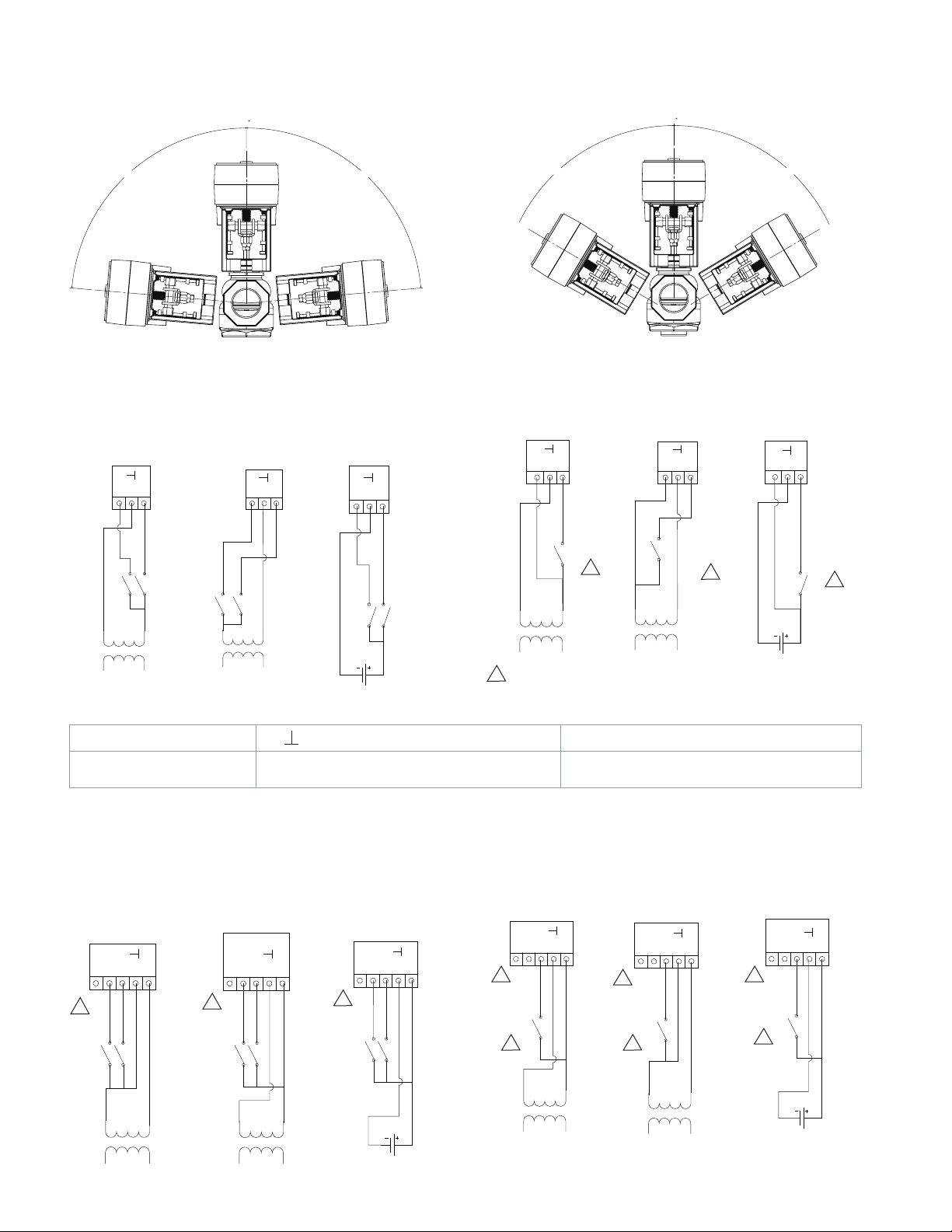
IP51 and NEMA Type 2 Allowable Mounting Orientation IP53 and NEMA Type 2 Allowable Mounting Orientation
0
0
Installation Instruction
85° 85°
Wiring
MG350V-24F Three Wire Floating Wiring
24 VAC
Floating Sourcing
Y1
24
Y2
24H24G
MG350V-24F Terminals
Y1
Extends the actuator linkage
and lowers the valve stem
24 VAC
Floating Sinking
Y1
24
24H24G
Floating Sourcing
Y2
24
24 Vac neutral or 24 Vdc common (Ref) for 24 Vac
sourcing and 24 Vdc, 24 Vac hot for 24 Vac sinking
24 VDC
Y1
24
Y2
60° 60°
MG350V-24F Two Position (On/Off) Wiring
24 VAC Two
Position Sourcing
Y1
24
Y2
24H24G
1
24 VAC Two
Position Sinking
Y1
24
Y2
24H24G
24 VDC24 Ref
1
With a two-position (on/o) wire connection Y2 closed (powered)
retracts the linkage and raises the valve stem. Y2 open (unpowered)
extends the linkage and lowers the valve stem.
Y2
Retracts the actuator linkage and raises the valve
stem
24 VDC Two
Position Sourcing
1
Y1
24
Y2
1
24 VDC24 Ref
NOTE: The MG350V-24F actuator is powered by Y1 and/or Y2. If both Y1 and Y2 are powered at the same time, then the actuator retracts linkage and raises the stem.
MGF350V-24FP Three Wire Floating with Position Output
Signal Wiring
24 VAC
Floating Sinking
UY2Y1
24
24~
1
24H24G
© 2017 Schneider Electric. A ll righ ts rese rved. All tr ademar ks are ow ned by Sc hneide r Electric Indu stries SAS or i ts affiliated companies. Februa ry, 2019 tc
Docume nt Number: F-278 52-11
24 VAC
Floating Sourcing
UY2Y1
24
24~
1
24H24G
24 VDC
Floating Sourcing
UY2Y1
24
24~
1
24 VDC24 Ref
MGF350V-24FP PWM with Position Output Signal Wiring
24 VAC Modulating
PWM Sourcing
UY2Y1
24
24~
1
PWM
2
24H24G
24 VAC Modulating
PWM Sinking
UY2Y1
24
24~
1
PWM
2
24H24G
24 VDC
Modulating PWM
UY2Y1
24
1
PWM
2
24~
24 VDC24 Ref
Page 5

Page 6

Page 7

DIP Switch Settings
MGF350V-24FP
Switch 1 Switch 2 Switch 3 Switch 4
Function Not Used Position Feedback Output
ON Position
(Switch up)
OFF Position
(Switch down)
1
The PWM input signal configuration responds to a timed pulsed signal (consisting of a leading and trailing edge) with a period between the minimum pulse width
setting (0.1 or 0.59 sec depending upon the setting of switch 3) and the maximum pulse width setting (25.5 or 2.93 sec depending upon the setting of switch 3). The
actuator responds to the width of the pulse relative to the pulse width span selected by switch 3. For example, if switch 3 is OFF, the actuator proportionally responds
to pulses between 0.59 sec and 2.93. sec. Thus, if the actuator receives a pulse consisting of a leading and trailing edge for 1.37 sec, the actuator positions the valve
stem to 33.3% because 1.37 sec is 33.3% between 0.59 and 2.93 sec. When setup for the PWM mode, the actuator responds to the last pulse signal received even if
the actuator is moving when the pulse is received.
Not Used 0 … 5 Vdc Output Signal 0.1 … 25.5 sec
Not Used 2 … 10 Vdc Output Signal 0.59 … 2.93 sec
Signal Selection
MG350V-24M
Switch 1 Switch 2 Switch 3* Switch 4
Function Not Used Not Used Input Signal Action Voltage Input Signal
ON Position (Switch up) Not Used Not Used Reverse Acting - a decrease in input signal extends the
OFF Position (Switch down) Not Used Not Used Direct Acting - an increase in input signal extends the
valve linkage and lowers the valve stem
valve linkage and lowers the valve stem
PWM Input Signal Range Selection,
only valid if Switch 4 is ON
1
1
Floating or PWM Input Selection
PWM Input Signal
Floating Input Signal
Range
2 … 10 Vdc
0 … 10 Vdc
Installation Instruction
MGF350V-24MP
Switch 1 Switch 2 Switch 3 * Switch 4
Function Selects internal 500 Ohm resistor for 4 …
ON Position
(Switch up)
OFF Position
(Switch
down)
* Switch 3: Direct Acting: 0% (0 Vdc (0...10 mode), or 2 Vdc (2...10 mode) = fully Retracted. 100% (10 Vdc) = fully Extended.
Reverse Mode: 0% (0 Vdc (0...10 mode), or 2 Vdc (2...10 mode) = fully Extended 100% (10 Vdc) = fully Retracted.
20 mA input signals, this also selects a 2
… 10 Vdc input signal (overriding switch 4
when it is in the ON position)
Internal 500 Ohm resistor connected for 4
… 20 mA input signal
Internal 500 Ohm resistor not connected 2 … 10 Vdc Output
Position Feedback
Output Signal Selection
0 … 5 Vdc Output
Signal
Signal
Input Signal Action Voltage Input Signal
Reverse Acting - a decrease
in input signal extends the
actuator linkage and lowers the
valve stem
Direct Acting - an increase
in input signal extends the
actuator linkage and lowers the
valve stem
Range, only valid if
Switch 1 is OFF
2 … 10 Vdc
0 … 10 Vdc
DIP Switch Operation
The MGF350V-24FP, MG350V-24M, and MGF350V-24MP actuators have a DIP switch block located under the cover to the left of
the wiring terminal. The MG350V series actuators are shipped with all their DIP switches in the OFF (down) position. If any DIP
switch is changed while the actuator is unpowered, it recognizes the DIP switch change the next time the actuator is powered,
initiates its calibration sequence, and then controls according to the latest DIP switch setting. If a DIP switch is changed while the
actuator is powered, it recognizes the DIP switch change, initiates its calibration sequence after 15 seconds, and then controls according to the latest DIP switch setting.
Auto-Calibration Operation
MGF350V-24FP, MG350V-24M (no position output signal), MGF350V-24MP actuators with DIP switches have an auto-calibration
program. Auto-calibration occurs the first time the actuator is mounted to the valve and powered, as well as any time a DIP switch
is changed. During the auto-calibration procedure, the actuator strokes the valve full stem down (actuator linkage extended) to
full stem up (actuator linkage retracted) in order to identify the two end of travel points. The input signal is then spanned to match
this travel distance. The valve calibration data is stored in permanent memory, and the actuator resumes normal operation from its
input signal.
© 2017 Schneider Electric. A ll righ ts rese rved. All tr ademar ks are ow ned by Sc hneide r Electric Indu stries SAS or i ts affiliated companies. Februa ry, 2019 tc
Docume nt Number: F-278 52-11
Page 8

Installation Instruction
During the calibration process, the actuator’s LED provides indication of calibration status, and the actuator’s position output signal indicates that it is in calibration mode. See the LED Operation section for more details. If the actuator is unable to calibrate, it
provides an LED status error. After the actuator has calibrated and is powered after a power failure, the actuator strokes the valve
full stem up (actuator linkage retracted), and then responds to its control signal.
The auto-calibration process can also be manually initiated by changing any DIP switch. If a DIP switch is changed while the actuator is unpowered, it recognizes the DIP switch change the next time the actuator is powered, initiates its calibration sequence,
and then controls according to the latest DIP switch setting. If a DIP switch is changed while the actuator is powered it recognizes
the DIP switch change, initiates its calibration sequence after 15 seconds, and then controls according to the latest DIP switch
setting.
Power Up Operation
The MGF350V-24FP, MG350V-24M, and MGF350V-24MP actuators remain in their last commanded position with no power applied. When power is applied, the actuator strokes the valve stem full up (actuator linkage retracted). While the actuator is retracting to its retracted position, its position feedback output signal (for MGF350V-24FP and MG350V-MP models only) remains at 0.4
Vdc (if Switch 2 is OFF) or 0 Vdc (if Switch 2 is ON). After the valve stem reaches its full up position (actuator linkage retracted),
the actuator then positions the valve in accordance to its control input signal and the position output signal indicates the valve
stem position.
The MG350V-24F actuators remains in their last commanded position with no power applied. When power is applied, the actuator
operates in accordance to its input control signals to retract or extend the valve stem.
Positioning and Sensitivity
The MG350 series actuators include a built-in microprocessor that provides accurate motor control and overload protection at all
of its stroke positions. The microprocessor constantly monitors the rotation of the stepper motor and stops the pulses to the motor
when it senses a stall condition. The proportional MG350V-24M and MGF350V-24MP actuators include a 1% positioning sensitivity
and “a change of direction” algorithm with a wider 2.5% sensitivity to accurately follow the proportional control signal while not
responding unnecessarily to electric noise and control input instability. The floating MGF350V-24FP accumulates repeated small
drive open and drive closed commands and positions the valve when the commands are consistently in the same direction to
provide accuracy while not responding unnecessarily to electric noise and control input instability.
Manual Override Operation
Use the manual override to manually position the actuator
when it is not powered. The actuator stays in the selected position until powered. After power is applied, the actuator strokes
the valve full stem up (actuator linkage retracted), then positions the valve according to its control input signal. The manual
override accepts a 3 mm allen wrench. Press firmly (depressing the wrench downward approximately 1/8” (3 mm) into the
actuator) and continue to hold the wrench in the depressed
position, then turn the wrench CCW to extend the actuator
spindle, lowering the valve stem, or CW to retract the actuator
spindle, raising the valve stem. It takes approximately 3 …
3-1/2 manual override wrench turns to fully stroke the valve
stem (each manual override turn moves the valve stem about
5/32” (4 mm).
Note: If the allen wrench is not seated properly or if the user
does not press firmly downward, it will not engage, and the
wrench may spin inside the nut.
3 mm allen wrench
(not included with the
actuator)
Manual Override
LED
viewing
port
© 2017 Schneider Electric. A ll righ ts rese rved. All tr ademar ks are ow ned by Sc hneide r Electric Indu stries SAS or i ts affiliated companies. Februa ry, 2019 tc
Docume nt Number: F-278 52-11
Page 9

LED Operation
MGF350V-24FP, MG350V-24M, and MGF350V-24MP Normal Operation LED Status
LED
Blinking Pattern
Orange
Green
Red
Orange
Orange Green Red
Cycles on
for 1/3 sec
Blinks once
every sec
Green -
1
See the Auto-Calibration Operations section for a complete explanation on the Auto-calibration process
MG350V-24F Normal Operation LED Status
LED
Blinking
Pattern
Orange
Green -
Orange Green Red
Blinks once
every sec
LED Color
Cycles on for
1/3 sec
- -
Blinks once
every sec
LED Color
- -
Blinks once
every sec
Cycles
on for
1/3 sec
-
Function Description
During calibration, the three LED colors flash until
Auto-Calibration Mode
1
the calibration is complete (orange, green, red,
repeated). The actuator’s position output signal is 0.4
Vdc during the calibration process (MGF350V-24FP
and MGF350V-24MP models only).
Indicates the actuator linkage is extending,
which lowers the valve stem
Indicates the actuator linkage is retracting,
Blinks every second when the actuator is moving
which raises the valve stem
Function Description
Indicates the actuator linkage is extending, which lowers the valve
stem
Indicates the actuator linkage is retracting, which raises the valve
stem
Installation Instruction
Blinks every second when the
actuator is moving
MGF350V-24FP, MG350V-24M, and MGF350V-24MP Alarm LED Operation
LED
Blinking Pattern
Each color cycles
on for 1/3 sec
LED
Color
Orange
Green
Red
Description Recommended Actions Alarm Type
During calibration the three LED colors flash
until the calibration is complete (orange,
Wait for the calibration process to finish Auto-Calibration
3
Mode
green, red, repeated). The actuator’s
position output signal is 0.4 Vdc during the
calibration process (MGF350V-24FP and
MGF350V-24MP models only).
Solid Red Travel during calibration revealed inad-
equate output stroke.
Check freedom of valve stem movement
and proper linkage connection, replace
Critical
1
actuator if necessary
3 seconds On,
1 second Off
Red Unexpected stalling Check for freedom of valve stem move-
ment and proper linkage connection,
Maintenance 1.0 Vdc
possible debris on the valve body, and for
proper DIP switch setup
6 seconds On,
1 second Off
Red Out of range 2 … 10 Vdc/4 … 20 mA input
signal
Check the input signal range: underrange
(below 2 Vdc) for MG350V-24M, and
Low Priority 1.3 Vdc
MGF350V-24MP when configured for a 2
… 10 Vdc input signal (DIP switch 4 ON)
Solid Red Actuator fault Replace actuator Critical
1
The actuator does not move the valve stem when a Critical Alarm is present. It does continue to position the valve if a Maintenance or Low Priority Alarm is present.
2
The Position Feedback Output Signal Override Voltage is valid for the MGF350V-24FP and MGF350V-24MP models only when configured for a 2 … 10 Vdc position
1
output signal (DIP switch 2 OFF). The Position Feedback Output Signal Override Voltage overrides the normal 2 … 10 Vdc output voltage that indicates the valve stem
position. The Position Feedback Output Signal Override Voltages do not occur when the position output signal is configured for 0 … 5 Vdc output range (DIP switch 1
OFF).
3
See the Auto-Calibration Operations section for a complete explanation on the Auto-Calibration process.
Position Feedback
1
Output Signal
Override Voltage
0.4 Vdc
0.7 Vdc
1.6 Vdc
2
© 2017 Schneider Electric. A ll righ ts rese rved. All tr ademar ks are ow ned by Sc hneide r Electric Indu stries SAS or i ts affiliated companies. Februa ry, 2019 tc
Docume nt Number: F-278 52-11
Page 10

Page 11

 Loading...