

Page 1
Specification Sheet
MG350-24F
SmartX Globe Valve Actuator
Product Description
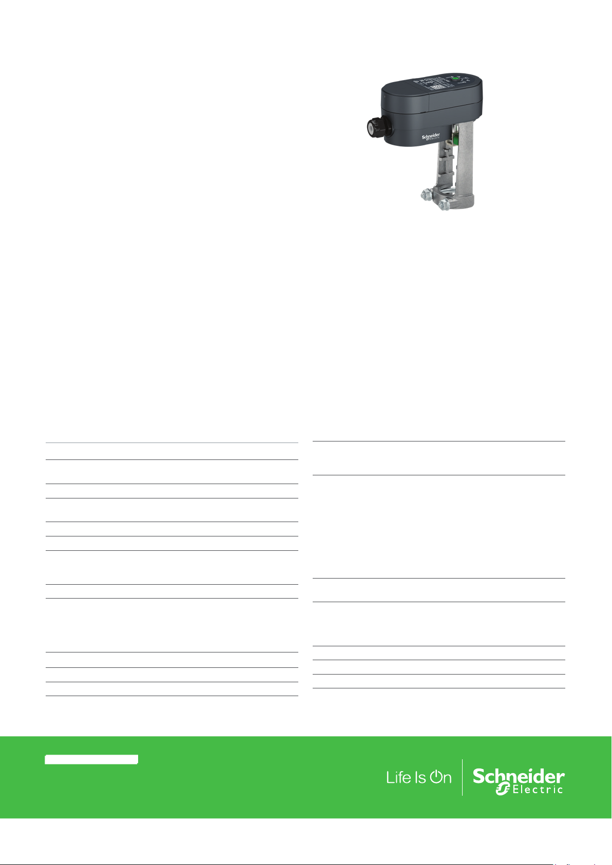
The MG350-24F is a compact electro-mechanical actuator
for controlling two-way and three-way Venta globe valves
V211, V211T, V241, V311, and V311T and V341.
The MG350-24F is a dual, 2 position / 3 point floating actuator within the SmartX Actuator family. The MG350 actuators
are primarily designed for applications where the demands
on speed and thrust are relatively small, such as:
• Mixing and injection heating circuits
• Small air handling systems
• Large Fan coil units
Specifications
Supply voltage
Power Consumption (50Hz),
full load Running 3.5 W
Transformer sizing 5.2 VA
Running Time 4 s/mm (Full stroke time,
Max. Stroke 21.5 mm
Force 350 N
Control
3 wire Floating
2 Position on/off
Minimum input pulse 100 msec
Ambient Temperature
Range
Ambient Operational Range
Storage temperature Range
Ambient humidity max . 95%
Protection rating IP 53 (vertically mounted)
Sound power level max. 30 dBA
24 Vac/dc ±20% 50/60 Hz
Venta Valves = 80 sec)
Dependant upon wiring, page 3
24 Vac/dc or 0V
NO or NC
–5…+55°C (for valve fluid
temperatures up to 130°C)
–40…+70°C
Features
• High Functionality
– Stable force control with stall protection
– Dual 3 Point floating and 2 position control.
– Sink or source floating control
– High Resolution PCBA and motor transmission for fine
valve plug position and excellent flow control.
• LED status indication
– Bi-color LED to indicate direction of movement when
under power.
• Removable terminal block and cable gland for ease of
installation.
• Compact Construction: Optimally designed to fit Venta
valves with 20mm Stroke.
Key Materials
Yoke
Housing
Standards/Directives
ElectroMagnetic Compatability [EMC]
Low voltage directive [LVD]
Restriction of Hazardous
Substances [RoHS2]
Heat
Humidity
Cold
Vibration
Manual Override 3 mm Hex (T style hand tool
Position indication Yoke position indicator with red and
blue position markers for hot and
cold pipe indication (green position
indicator for closed valve)
Cable Gland wire size 2.4 to 6.6 mm
Conduit hole M20
Weight (shipping) 0.36 kg
Aluminum
PBT/PC
2014/30/EU
2014/35/EU
2011/65/EC
IEC 60068-2-2
IEC 60068-2-3
IEC 60068-2-1
IEC 60068-2-6
recommend)
© 2016 Schne ider Ele ctric. All rights rese rved. All trademar ks are ow ned by Sch neider Electr ic Indust ries S AS or its affi liated co mpanie s. Januar y, 2019 tc
Docume nt Numbe r: F-279 80- 5
Page 2
Specification Sheet
180
Function
Actuator
The actuator utilizes a stepper motor to accurately position
the main spindle via a gearbox based on the command
received from the controller.
Control Signal
This MG350-24F SmartX Actuator series can be controlled
either by 3 wire floating (increase/decrease) switched either
between the 24 Vac/dc supply or by the 0V return. 2 position
control for the actuator to retract or extend (IN/OUT) proving
a normally open or normally closed valve is possible by configuring the wiring, see wiring diagrams on page 3.
Manual Operation
A 3mm hex key can be used to manually drive and position
the MG350 SmartX Actuator. Do not depress the hex key
during normal operation. The hex key is not supplied with the
actuator.
The Hex key should be depressed firmly to disengage the
main drive motor and continue to be depressed whilst rotating the key to adjust actuator position. It takes approximately
5 full rotations of the manual override to fully stroke the valve,
each manual override turn moves the valve stem about 4
mm. There may be a load click as the main drive motor reengages after a manual operation.
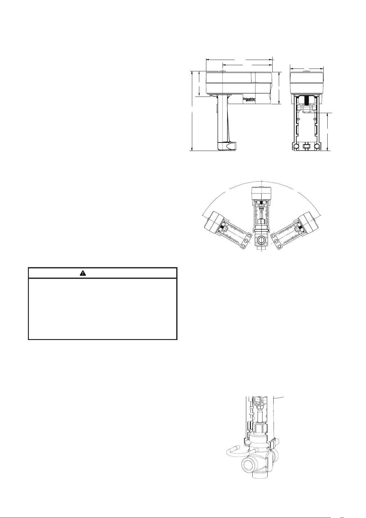
Dimensions (mm)
149
111
57
60°
75
72
85
0°
60°
Maintenance
The actuator is maintenance-free.
Mounting
WARNING
RISK OF BURNS OR FLYING PARTS
If the valve stem, spindle, or plug has been damaged, it may
blow out under pressure while servicing the actuator.
Isolate and depressurize the v
•
•
Manually check valve stem, spindle, or plug integrity by
moving it within the valve. If the part can be removed,
replace the valve assembly
Failure to follow these instructions may result in death or
serious injury.
Mount the actuator horizontally, vertically, or in any position in
between, but not upside down. If the media temperature is
above 120°C, install the actuator at an angle over the pipework to reduce the radiant heat influence.
For water ingress protection, do not mount actuators below
the horizontal plane of the valve. IP63 will be achieved with
a mounting orientation from vertical to 60 deg. IP51 will be
achieved to 85 deg.
alve before servicing.
.
Mounting the Actuator on the Venta Valve
A square nut is supplied with the actuator and is to be
mounted onto the top edge of the valve stem before the
actuator is mounted. The actuator is delivered so it is not
needed to operate the manual override to assemble the
product.
1.
Assemble the square nut to the top edge of the valve
stem leaving some clearance between this nut and the
flanged nut below.
2.
Position the valve stem by hand to align with the
actuator clasp.
3.
Slide the actuator onto the valve neck, aligning the
actuator clasp in between the square nut and flanged
nut.
4.
Push the actuator down to align and insert the U-bolt
brace; secure brace with the flanged nuts.
5.
Tighten the valve stem flanged nut.
Januar y, 2019 tc © 2 016 Schnei der Electric. A ll righ ts rese rved . All tra demar ks are own ed by Schn eider El ectri c Indust ries S AS or its a ffil iated co mpanie s.
Document Number: F-27980-5
Page 3

Specification Sheet
Colored Valve Limit Indicators
The colored end stop limits on the yoke are provided to show
the valve plug position according to the valve stroke. After
mounting the actuator, arrange the position and colour of the
limits as per the table below, discarding either the red or blue
as needed.
Squeeze the end stop limits either side of the actuator cross
bar and initiate a calibration sequence, the actuator will then
automatically push the end stop limits to the exact limits of
Terminal Block Connection
Y1
Extends the actuator
linkage and lowers the
valve stem
24
24 Vac/dc supply for
sinking
24 Vac neutral or
24 Vdc common for
sourcing
NOTE: The MG350-24F actuator is powered by Y1 and/or Y2. If both
Y1 and Y2 are powered at the same time, then the actuator retracts
linkage and raises the stem.
Wire Sizing
Cable type Maximum length Minimum cross sectional area
Power 100 m (328 ft) 1.5 mm2 (AWG 16)
Y2
Retracts the
actuator linkage
and raises the
valve stem
the valve stroke. It is recommended to set-up the colored
valve end stop limits according to the valve and media during commissioning.
Position the limits as follows:
Green end stop Closed valve
Red end stop Open heating circuit
Blue end stop Chilled water circuit
Direction of Operation
Y1
Y2
4 s/mm
Wiring
Three Wire Floating
24 VAC
Floating Sourcing
Y1
24
Y2
COM
24 Vac
Normal LED Operation
LED Color Blinking pattern Function
Orange light 0.3 sec,
Green light 0.3 sec,
every second
every second.
24 VAC
Floating Sinking
COM
Y1
24
Y2
24 Vac
Indicates actuator is extending, lowering
the valve stem to open the valve
Indicates actuator is retracting, lifting the
valve stem to close the valve
24 VDC
Floating Sourcing
Y1
24
24 Vdc
Return
Y2
24 Vdc
Two Position (On/Off)
24 VAC Two
Position Sourcing
Y1
24
Y2
24 Vac
24 VAC Two
Position Sinking
COMCOM
Y1
24
Y2
24 Vac
24 VDC Two
Position Sourcing
Y1
24
24 Vdc
Return
LED
Y2
24 Vdc
© 2016 Schne ider Ele ctric. All rights rese rved. All trademar ks are ow ned by Sch neider Electr ic Indust ries S AS or its affi liated co mpanie s. Januar y, 2019 tc
Docume nt Numbe r: F-279 80- 5
Page 4

Specification Sheet
Januar y, 2019 tc © 2 016 Schnei der Electric. A ll righ ts rese rved . All tra demar ks are own ed by Schn eider El ectri c Indust ries S AS or its a ffil iated co mpanie s.
Document Number: F-27980-5
 Loading...