

Page 1
Page 2
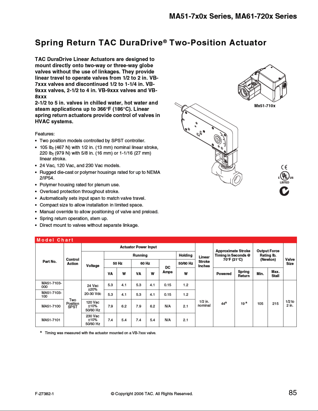
MA51-7x0x Series, MA61-720x Series
Model Chart(Continued)
Actuator Power Input
Part No.
MA51-7203
MA51-7200
MA51-7201
MA61-7203
MA61-7200
MA61-7201
a
Timing was measured with no load applied to the actuator.
b
Current VB-7xxx Series valves and discontinued VB-9xxx Series valves (1-1/4 in. on ly).
c
Current VB-9xxx Series valves (2-1/2 to 4 in.), current VB-8xxx (2-1/2 to 5 in.) Series valves, and discontinued VB-9xxx (1-1/2 to 2 in.) Series valves.
Control
Action
2
Position
Voltage
24 Vac
r20%
22-30 Vdc
120 Vac
r10%
230 Vac
r10%
24 Vac
r20%
22-30 Vdc
120 Vac
r10%
230 Vac
r10%
50 Hz 60 Hz
VA W VA W W Powered
9.8 7.5 9.7 7.5 .29 2.8
11.7 8.8 10.0 8.4 N/A 3.6/5.0
15.5 9.5 10.6 8.5 N/A 4.6/3.3
9.8 7.5 9.7 7.5 .29 2.8
11.7 8.8 10.0 8.4 N/A 3.6/5.0
15.5 9.5 10.6 8.5 N/A 4.6/3.3
Running Holding
DC
Amps
50/60 Hz
Approximate Stroke
Linea r
Stroke
Inches
1-1/16
Timi ng in S econds @
5/8 <100
70°F (21°C)
a
a
<190
Spring
Return
<35
<40
a
a
Output Force
Rating lb.
(Newton)
Max.
Min.
Stall
220
(979)
495
(2202)
Valve
Size
1-1/4
to 2
in.
2-1/2
to 4
or 5
in.
b
c
Specifications
Inputs
Control signal On-off spring return, SPST control contacts or Triacs (500 mA rated).
Power
Connections
Outputs
Mechanical
24 Vac ± 20%, Class 2, 22 to 30 Vdc, 120 Vac ± 10%, 230 Vac ± 10%, 50/60 Hz. All 24 Vac circuits are
Class 2. All circuits 30 Vac and above are Class 1.
Models with -0xx have 3 ft. (91 cm) appliance wire connections. Models with -1xx have 3 ft. (91 cm)
plenum wire connections. Enclosure accepts 1/2 in. (13 mm) conduit connectors. For M20 Metric
connector, use AM-756 adaptor.
Motor Type: Brushless DC.
Linear Stroke: MA51-720x: 5/8 in. (16 mm). MA61-720x: 1-1/16 in. (27 mm). MA51-710x: 1/2 in. (13
mm) nominal.
Approximate Stroke Timing: See Model Chart.
Manual Override: Allows positioning of valve and preload using manual crank.
86
© Copyright 2006 TAC. All Rights Reserved. F-27382-1
Page 3

Specifications (Continued)
Environment
Shipping and Storage: -40 to 160qF (-40 to 71qC).
Ambient temperature limits
Operating: MA51-720x/MA61-720x: 0 to 140qF (-18 to 60qC). MA51-710x: -22 to 140qF (-30 to 60qC).
Temperature Restrictions: For maximum ambient 140qF (60qC) the maximum allowable fluid
temperature should not exceed valve rating. See F-27252 Selection Guide for specific ratings.
MA51-7x0x Series, MA61-720x Series
Actuator
MA51-720x
MA61-720x
MA61-720x
Max. Allowable
Ambient @ Max. Fluid
Temperatures
140qF (60qC) @ 281qF
(138 qC)
120qF (49qC) @ 300qF
(149 qC)
100qF (38qC) @ 340qF
(171 qC)
90qF (32qC) @ 366qF
(186 qC)
140qF (60qC) @ 300qF
(149 qC)
140qF (60qC) @ 281qF
(138 qC)
Valve Body
VB-721x, 722x
VB-73xx
VB-725x, 726x
VB-727x, 728x
2-1/2 to 4 in. VB-931x
2-1/2 to 4 in. VB-92xx, 2-1/2 to 5 in. VB-8xxx
Humidity MAx1-72xx: 15 to 95% RH, non-condensing. MA51-710x: 5 to 95% RH, non-condensing.
Locations
NEMA 1. NEMA 2 (enclosure is air plenum rated), UL Type 2 (IEC IP54) with customer supplied water
tight conduit connections.
MA51-71xx: 6-5/16 H x 6-49/64 W x 3-1/2 D in. (160 x 170 x 89 mm).
Dimensions
MA51-72xx: 7 H x 9-1/4 W x 2-33/64 D in. (178 x 235 x 64 mm).
MA61-720x: 9-1/2 H x 11-1/8 W x 2-33/64 D in. (241 x 283 x 64 mm).
Agency Listings
UL 873 Underwriters Laboratories (File #E9429 Category Temperature-Indicating and Regulating Equipment).
CUL UL Listed for use in Canada by Underwriters Laboratories. Canadian Standards C22-2 No. 24-93.
European Community EMC Directive (89/336/EEC). Low Voltage Directive (72/23/EEC).
Australia
This product meets requirements to bear the C-Tick Mark according to the terms specified by the
Communications Authority under the Radio Communications Act 1992.
F-27382-1 © Copyright 2006 TAC. All Rights Reserved. 87
Page 4

MA51-7x0x Series, MA61-720x Series
Valve Size Chart.
Valve Body
Part Number
P Code
Size
inches
MA51-710x MA51-720x MA61-720x
Close-Off Pressure PSI
1, 2,3 or 4 1/2 250
VB-721X-000-4-P
VB-7253-000-4-P
VB-7273-000-4-P
5 or 6 3/4 200
7 or 8 1 150
9 1-1/4 90 150
10 1-1/2 60 100
11 2 32 65
1,2,3 or 4 1/2 250
VB-722X-000-4-P
VB-7263-000-4-P
VB-7283-000-4-P
5 or 6 3/4 200
7 or 8 1 90
9 1-1/4 60 150
10 1-1/2 35 100
11 2 20 65
2 or 4 1/2 250
6 3/4 200
VB-731X-000-4-P
7 or 8 1 90
9 1-1/4 60 150
10 1-1/2 35 100
11 2 20 65
4 1/2 250
6 3/4 250
VB-732X-000-4-P
7 or 8 1 250
9 1-1/4 250 250
10 1-1/2 250 250
11 2 250 250
12 2-1/2 125
VB-8213-000-5-P
VB-8223-000-5-P
13 3 125
14 4 125
15 5 125
12 2-1/2 35
VB-8303-000-5-P
13 3 35
14 4 35
15 5 35
1,2,3 or 4 1/2 250
VB-921X-000-4-P
VB-9253-000-4-P
VB-9273-000-4-P
5 or 6 3/4 200
7 or 8 1 150
9 1-1/4 90 150
10 1-1/2 100 AM-733 or AM-734
11 2 65 AM-733 or AM-734
1, 2, 3, or 4 1/2 250
VB-922X-000-4-P
VB-9263-000-4-P
VB-9283-000-4-P
5 or 6 3/4 200
7 or 8 1 90
9 1-1/4 60 150
10 1-1/2 100 AM-733 or AM-734
11 2 65 AM-733 or AM-734
a
Note: Maximum valve differential operating pressures MUST be observed. Please consult our Valve Products Catalog F-27384
to assure the operating differential for your application is followed.
b
Use AM-733 with valves with date codes after 9404. Use AM-734 with valves with date codes before 9404.
Valve Compatibility Table, Continued..
Valve Body
Part Number
P Code
Size
inches
MA51-710x MA51-720x MA61-720x
2 or 4 1/2 250
6 3/4 200
VB-931X-000-4-P
7 or 8 1 90
9 1-1/4 60 150
10 1-1/2 65 AM-733 or AM-734
11 2 65 AM-733 or AM-734
2 or 4 1/2 250
6 3/4 250
VB-9323-000-4-P
7 or 8 1 250
9 1-1/4 250 250
10 1-1/2 250 AM-733 or AM-734
11 2 250 AM-733 or AM-734
VB-92X3-000-X-P
VB-9313-000-X-P
a
Note: Maximum valve differential operating pressures MUST be observed. Please consult our Valve Products Catalog F-27384
12 2-1/2 33
13 3 22
14 4 12
to assure the operating differential for your application is followed.
Close-Off Pressure PSI
a
Required Retrofit Kit
a
Required Retrofit Kit
b
b
b
b
b
b
b
b
88
© Copyright 2006 TAC. All Rights Reserved. F-27382-1
Page 5

MA51-7x0x Series, MA61-720x Series
Accessories
Model No. Description
MA51-72xx, MA61-72xx
AM-731 Mounting kit - Mx51 - 720x (included with actuator).
AM-732 Mounting kit - Mx61 - 720x (included with actuator).
AM-733 Retrofit kit - discontinued VB-9xxx 1-1/2 to 2 in. valves after 9404 date code.
AM-734 Retrofit kit 1 - discontinued VB-9xxx - 1/2 to 2 in. valves prior to 9 404 date code.
AM-756 Metric conduit adapter M20 x 1.5 to 1/2 in. NPT.
AM-763 1/8 in. Hex crank for manual override.
MA51-710x
AM-756 Metric conduit adapter M20 x 1.5 to 1/2 in NPT.
AM-770 Replacement valve linkage parts kit.
AM-764 Linkage kit for damper applications.
Typical Applications
24 Vac Transformer
or 20-30 Vdc
Line
Volts
1
3
SPST Control Contact
120 Vac or
230 Vac
1
3
SPST Control Contact
1 Provide overload protection and disconnect as
required.
2 Cable on some models contains more wires
than are used in applications. Only those
wires actually used are shown.
3
Applied power extends actuator. Spring
returns when power is removed.
Blk
Red
L1
L2
Com
Hot (+DC)
N
Hot
Figure 1 Typical Wiring Diagrams for Two Position Actuators.
MA51-77203
MA51-7103-xxx
MA61-7203
2
MA51-7100-xxx
MA51-7101-xxx
MA51-7200
MA51-7201
MA61-7200
MA61-7201
2
Voltage L1 N L2 Hot
120 Vac White Black
230 Vac Blue Brown
F-27382-1 © Copyright 2006 TAC. All Rights Reserved. 89
 Loading...