

Page 1
Saitel DP
M58100000y / SM_SER
U
ser Manual
This manual provides information for the assembly, wiring, configuration and
maintenance of the SM_SER module.
SE-M581-USR
Publication Date (02/2020)
Read carefully the information contained in this manual before assembly, installation and use of the
equipment.
www.schneider-electric.com
Page 2
13/12/2019 User Manual – SM_SER
Change Control
Rev Date Description
01 13-12-2019 Initial edition
02 17-02-2020
General Information
The Saitel platform and all its components have been developed in accordance to the requirements
for a quality management system, complying with the ISO 9001:2015 Norm.
Document nº: SE-M581-USR
Revision/Date: 02 / 17-02-2020
File: SM_SER – User Manual_EN_02.pdf
Retention period: Permanent throughout its validation period + 3 years after
Reference Documents
User Manual Document Code
Easergy Builder User Manual FTE-S856-MSS
SM_CPU866e User Manual SE-M578-USR
The addressing table has been corrected (
its cancellation.
Table 2).
webApp User Manual FTE-S856-WPP
EOL Instructions SE-M581-EOLI
Saitel DR Platform user manual SE-F700-USR
Software Versions
The information in this manual is valid for the software versions listed below. This information is
also valid for later versions, although some parameters may change slightly:
Module
Baseline SM_CPU866e 11.06.12
Easergy Builder Tool 1.5.9
Software SM_SER SM_SER C0_01.00.08
RTU Software Easergy Builder (Plugin)
Module Version Plugin Version
Pag 2
Page 3

User Manual – SM_SER 13/12/2019
Content
1 SAFETY & HEALTH ................................................................................................ 4
2 GENERAL DESCRIPTION OF SM_SER ............................................................... 14
3 PHYSICAL MOUNTING & INSTALLING ............................................................... 19
4 MAINTENANCE & CONFIGURATION ................................................................... 29
5 TECHNICAL SPECIFICATION TABLE .................................................................. 43
Pag 3
Page 4

13/12/2019 User Manual – SM_SER
1 Safety & Health
Pag 4
Page 5

User Manual – SM_SER 13/12/2019
Content
1 SAFETY & HEALTH ................................................................................................ 4
1.1 INTRODUCTION ....................................................................................................... 6
1.1.1 I
1.1.2 P
1.2 I
1.3 S
1.4 I
1.5 E
1.5.1 E
1.5.2 F
1.6 H
1.7 T
1.7.1 P
1.7.2 E
1.7.3 S
1.8 T
1.9 P
1.10 D
NFORMATION OF SECURITY ............................................................................. 6
RESENTATION ............................................................................................... 6
NTRODUCTION TO SAFETY ..................................................................................... 7
YMBOLS AND LABELS ON THE EQUIPMENT ............................................................. 7
NSTALLATION, SETUP AND OPERATION................................................................... 8
ARTHING ............................................................................................................ 10
LECTRICAL SAFETY ..................................................................................... 10
UNCTIONAL EARTH (EMC) ........................................................................... 11
ANDLING ELECTRONIC COMPONENTS .................................................................. 11
ECHNICAL SPECIFICATIONS FOR SAFETY ............................................................. 11
ROTECTIVE ELEMENTS ................................................................................ 11
NVIRONMENTAL CONDITIONS ....................................................................... 12
TORAGE CONDITIONS .................................................................................. 12
ECHNICAL LABEL ............................................................................................... 12
ACKING AND UNPACKING .................................................................................... 13
ECOMMISSIONING AND DISPOSAL ...................................................................... 13
Pag 5
Page 6
13/12/2019 User Manual – SM_SER
DANGER indicates a hazardous situation which, if not avoided, will result in death or serious
WARNING
WARNING indicates a hazardous situation which, if not avoided, could result in death or
NOTICE
NOTICE is used to address practices not related to physical injury. The safety alert symbol shall
1.1 Introduction
1.1.1 Information of Security
Important information
Read these instructions carefully and look at the equipment to become familiar with the device
before trying to install, operate, service or maintain it. In this manual you can find different types of
messages associated with situations that have different level of risk for people and / or for the
equipment.
This symbol indicates "DANGER" or "WARNING". This symbol informs of an
electrical risk that will cause personal injuries if the instructions are not followed.
This symbol is associated to a safety alert. It is used to warn of possible personal
injury hazards. The user must follow all instructions or messages associated to this
symbol to avoid possible injuries.
injury.
serious injury.
not be used with this signal word.
To Keep in Mind
Electrical equipment should be installed, operated, serviced, and maintained only by qualified
personnel. No responsibility is assumed by Schneider Electric for any consequences arising out of
the use of this material.
A qualified person is who fulfill with requirements in paragraph 1.2
DANGER
1.1.2 Presentation
This manual provides information for a safe handling, commissioning and testing. This Safety
chapter also includes descriptions of the labels on the equipment.
Documentation for equipment ordered from Schneider Electric is dispatched separately from
manufactured goods and may not be received at the same time. Therefore, this guide is provided
to ensure that printed information which may be present on the equipment is fully understood by
the recipient.
Pag 6
Page 7
User Manual – SM_SER 13/12/2019
Before carrying out any work on the equipment the user should be familiar with the
THE EQUIPMENT.
WARNING
Before working with the terminal of connection, the device must be turned off and disconnected
The technical data in this safety guide is typical only, see the technical data section of the user
manual for specific details of a particular equipment.
contents of this Safety chapter and the ratings on the equipment’s rating label.
THE SAFETY SECTION MUST BE READ BEFORE STARTING ANY WORK ON
1.2 Introduction to Safety
The information in this section is intended to get that the equipment is properly installed and
handled in order to maintain it in safety conditions. It is assumed that everyone who will be
associated with the equipment will be familiar with the contents of that safety section.
When electrical equipment is in operation, dangerous voltages will be present in certain parts of the
equipment. Failure to observe warning notices, an incorrect use, or improper use may endanger
personnel and equipment and also cause personal injury or physical damage.
of the feeding.
Proper and safe operation of the equipment depends on appropriate shipping and handling, proper
storage, installation and commissioning, and on careful operation, maintenance and servicing. For
this reason, only qualified operator may work on or operate the equipment.
Qualified operator are individuals who:
• Have read and understood the information on the device and its user manual.
• Are familiar with the installation, commissioning, and operation of the equipment and of the
system to which it is being connected.
• Are able to safely perform switching operations in accordance with accepted safety
engineering practices and are authorized to energize and de-energize equipment and to
isolate, ground, and label it.
• Are trained in the care and use of safety apparatus in accordance with safety engineering
practices.
• Are trained in emergency procedures (first aid).
It is necessary to consider that the documentation of the device collects the instructions for its
installation, set up and operation. However, the manuals could not cover all the possible
circumstances neither include specific information on all the details.
In case of questions or specific problems, contact with his office of sales Schneider Electric or with
the center of attention to the customer and request the necessary information.
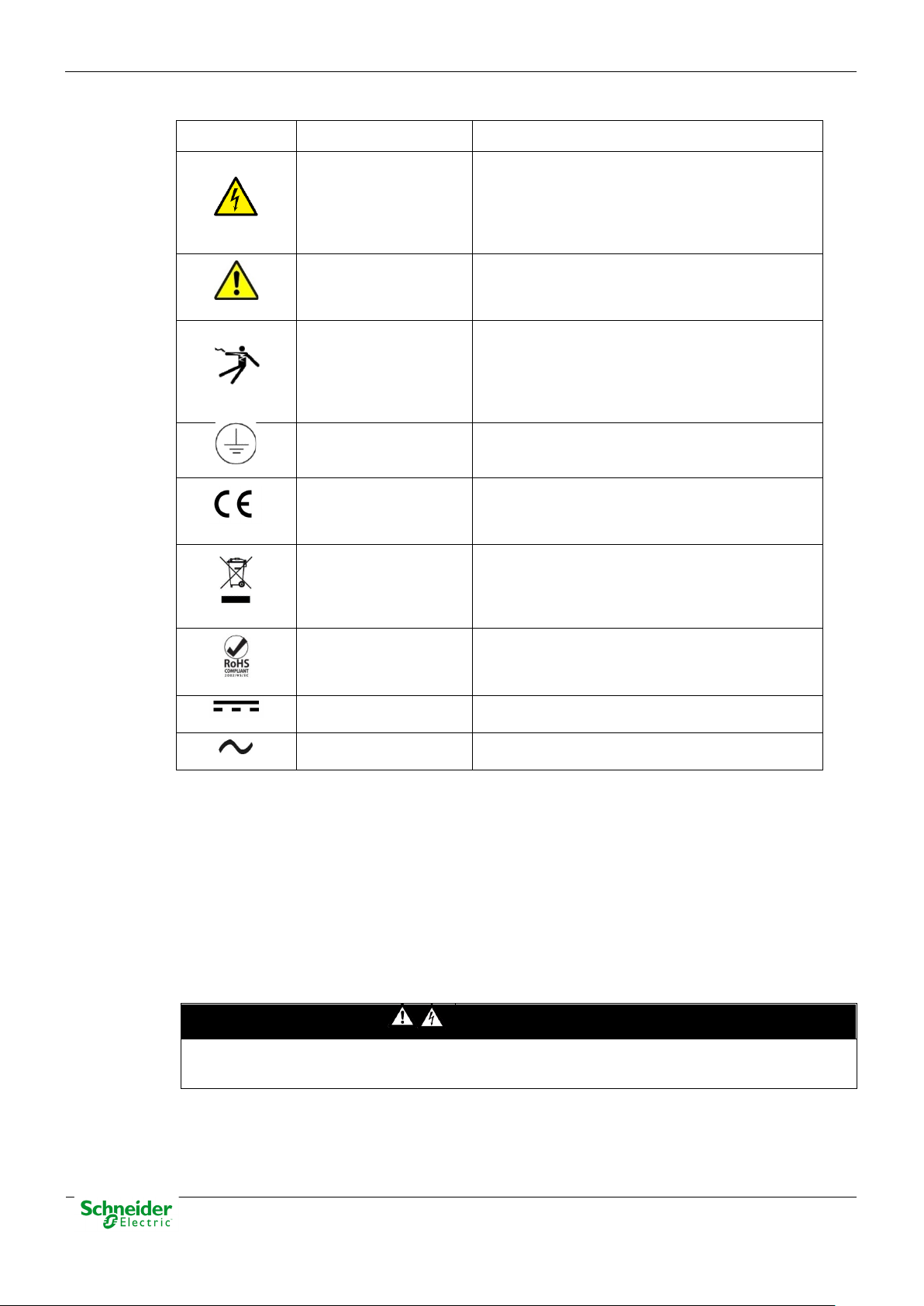
1.3 Symbols and Labels on the Equipment
Before the equipment is installed or commissioned, the user must understand the following
symbols, which may be used on the equipment or referred to in the user documentation.
Pag 7
Page 8
13/12/2019 User Manual – SM_SER
Symbol
Associated Text
Description
International Electrotechnical Commission (IEC)
Symbol associated with a risk alert. The user
American National Standards Institute (ANSI)
Associated symbol to the protective ground
This symbol indicates that the equipment has
Electronic device.
This symbol indicates that, at the end of its life,
The equipment has been designed and
Symbol of direct voltage (VDC).
Alternate Voltage
Symbol of alternate voltage (VAC).
Devices that handle dangerous tensions are marked with a sticker on the front label (size: 12,5
Table 1 – Symbols
Possibility of electric
chock
Caution, read the
manual.
Possibility of electric
chock
Protective earth
connection
CE Mark
Special instructions
must be followed for
discard it.
symbol associated to a DANGER or WARNING
message indicating that there is an electrical
risk. Failure to follow these instructions could
cause damage to people or death.
must read the manual before handling the
equipment.
symbol associated to a DANGER or WARNING
message indicating that there is an electrical
risk. Failure to follow these instructions could
cause damage to people or death.
connection. See paragraph 1.5.1 in this manual.
been developed in compliance with all
applicable European Directives.
this module must be discarded according to the
WEEE Directive (Waste Electrical and Electronic
Equipment).
Compliant with
RoHS.
Direct Voltage
manufactured according to RoHS Directive
(Restriction of Hazardous Substances).
1.4 Installation, Setup and Operation
There are several acquisition blocks in Saitel DP that use dangerous tensions (> 50 V). The user is
responsible to check that the characteristics of each device are adapted and convenient for his
installation. The user should read the instructions of installation before proceeding to the use or
maintenance of the devices.
Not following these instructions can be dangerous for the people and the devices.
DANGER
mm). This label must be visible all the time while the module is installed on the backplane.
The following products handle dangerous tensions:
Pag 8
Page 9
User Manual – SM_SER 13/12/2019
WARNING
If this type of cabinet isn't available, a barrier must be installed in order to avoid an accidental
NOTICE
Terminals will not be accessible to the user directly once it has made the installation of the
WARNING
Don’t use liquid products of cleanliness due to the presence of active parts.
• SM_DI32: Digital inputs module (P/N: M583x0000x).
• SM_PS40: Power supply module (P/N M5084x000x and M5085x000x).
• SM_PS: Power supply module (P/N M5155x000x).
• SM_DO16R and SM_DO32T: These modules do not handle high voltages, they will not be
marked at the factory. These modules must be marked to inform about the risk when some
equipment that manage voltage higher than 50 V are connected to digital outputs.
It is recommended to install the RTU inside a cabinet with a key. This cabinet only should be
opened by a qualified person.
contact with these dangerous elements. This barrier only should can be removed using a
special tool.
If the barrier has to be removed in order to access to equipment, personnel responsible for the
task must be sure that the barrier is installed again when the task is finished.
While the RTU is accessible for a user, all people must follow all instructions to prevent
electrical risk or discharges.
Not following these instructions can give like result that the device do not work properly
or even can damage to the people or devices.
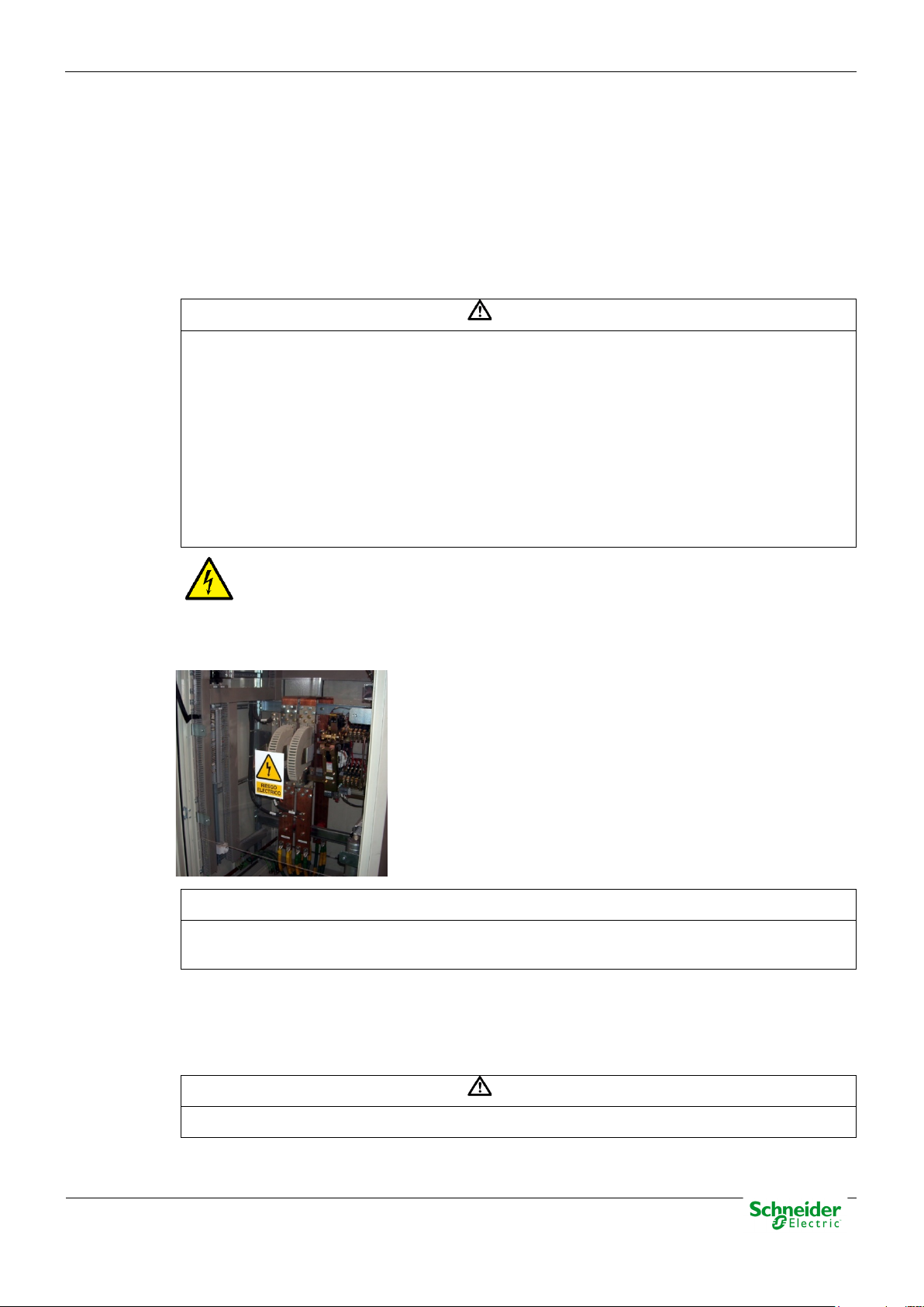
An electrical risk symbol with enough size must be included on the cabinet’s door or
on the barrier.
The following image shows an example:
Figure 1 – Barrier of protection for elements with dangerous voltages.
device. The cabinet will have to remain closed with key or the screen of installed protection.
The cabinet or installation must have a general switch placed just in the cable entry of the
installation (see paragraph 1.7.1 )
For the cleaning of the device it is only necessary using a dry cloth by the surface when it detects
excessive presence of dust or any element deposited on the surface.
Because of the variety of uses of the product, the managers of the application and use of this
device of control will have to take the measures to ensure the fulfillment of all the requests of
Pag 9
Page 10

13/12/2019 User Manual – SM_SER
WARNING
installation.
WARNING
All devices with high voltage must be disconnected before dismount a module.
WARNING
security and provision of each application. The requests do reference to the applicable laws,
regulations, codes and standard.
1.5 Earthing
Before energizer the device, it has to be placed to earth properly such as it indicates in sections
1.5.1 and 1.5.2 .
When installing the device, ground is the first thing that should be connected and the last one
that should be disconnected.
Saitel can need put to earth for two distinct needs:
• For purposes of electrical safety (Protective Earth, PE).
• Improve the behavior in Electromagnetic Compatibility (EMC) and derive perturbations to earth
(functional Earth).
1.5.1 Electrical Safety
Only qualified personnel, with knowledge about hazards associate with electrical equipment is
allowed to install Saitel DP. In general, the installation will be following IEC 61010-1
recommendations in order to be compliant with this norm.
When Saitel DP is mounted on back-panel, the backplane on is metallic enclosure
must be installed on a metallic surface. This surface must be connected to the ground
of the cabinet or installation according to the norm IEC 61010-1. When Saitel DP is
mounted on a chassis, this chassis must be connected to the ground of the
Saitel DP modules have a plastic enclosure offering protection for isolation faults. Earthing
In the cabinet where the module is mounted, a dedicated connection with green/yellow wire should
be used to have electric continuity to the installation protective earth. Use a wire with adequate
section according to IEC 61010.
Figure 2 – Yellow and Green cable for earthing.
The design and installation of the cabinet is responsible for compliance with all the existing
international and national electrical codes concerning protective grounding of any device.
Pag 10
Page 11
User Manual – SM_SER 13/12/2019
According to electrical safety standards:
WARNING
Never connect modules on the backplanes if the power supply hasn’t been disconnected of all
WARNING
The enclosure ONLY should be removed when is strictly necessary, because this action has a
WARNING
• The screw for ground must be exclusive for this use.
• The power voltage must be supplied by a power supply that offers double or reinforced
insulation against dangerous voltages.
1.5.2 Functional Earth (EMC)
A rear connector available in each module allows the bus connection and it offers protection in
case of electric derive. The EMC grounding is implemented via three pins of this connector.
circuits with high voltages.
The only modules with a ground connection are the power supplies (SM_PS and SM_PS40). Both
must be connected to the ground of the cabinet.
1.6 Handling Electronic Components
Saitel is susceptible to receive electrostatic discharges during the handling. It is necessary to take
the usual measures to minimize this risk, since serious damage to the equipment can be caused,
which may not be detected immediately but which may affect the reliability of the product.
risk for the equipment:
• Before removing the enclosure, the operator must be equipotential with the equipment.
• Avoid touching the electronic. The board must be always manipulated for the edges.
• If the equipment has to be passed between two persons, both must be equipotential.
• Put the module always on an antistatic surface or on a surface equipotential with you.
• During the storage and transport, the module will remain in the packaging.
Not following these instructions can give like result that the device do not work properly
or even can damage to the people or equipment.
1.7 Technical Specifications for Safety
1.7.1 Protective Elements
The cabinet's engineering and installation must include a general automatic switch next to the
cables' input in the cabinet; once the door is opened, high voltages must be interrupted inside. This
switch must be located at a place which is not accessible by a third person while the operator is
using the boards in the cabinet.
Moreover, the installation will incorporate a circuit breaker of 5A next to the cabinet protecting it
from possible overcurrent in the power supply.
Both switches will be labeled with the symbol O as "Off" and I as “On”.
Pag 11
Page 12
13/12/2019 User Manual – SM_SER
The connection / disconnection switch must be installed in a fixed element (for example the wall
WARNING
This equipment has been designed ONLY for indoor use.
of the cabinet) and it mustn’t break any earthing wire.
1.7.2 Environmental Conditions
The protection degree of the device is IP20.
If necessary, for use in an outdoor environment, it must be mounted in a specific cabinet providing
an IP54 degree of protection (typical and minimum for ATEX conditions), that is, protected against
dust and water splashes.
The electronic cards of the modules will be able to be tropicalized or no according to the option of
setting chosen. The tropicalized used is the AVR80, of the company ABchimie. It can consult all the
technical information of this type of finishing in http://www.abchimie.com/
Other data to take into account about the environmental are:
• Altitude until 2000 m.
• Operation temperature range: Between -40 ºC and 70 ºC. (IEC 60068-2-1 and IEC 60068-2-2).
• Maximum relative humidity of 95%. (IEC 60068-2-30)
.
• Degree of pollution II. (IEC 60255-5)
• Overvoltage transitory until levels of Category III. (IEC 60255-5)
1.7.3 Storage Conditions
The continuous exhibition to some high levels of humidity during the storage can cause damages
to the electronic components and reduce the useful life of the device.
We recommend that, in the enclosure of storage, the relative humidity do not exceed 50%.
Once that the Saitel devices have been unpacked, recommend that they are energized inside the
three following months. When an electrical device is installed, you have to leave sufficient time for
the acclimatization to the environmental temperature, before the activation. Once the equipment
has been unpacked, it is recommended that it be energized within the following three months.
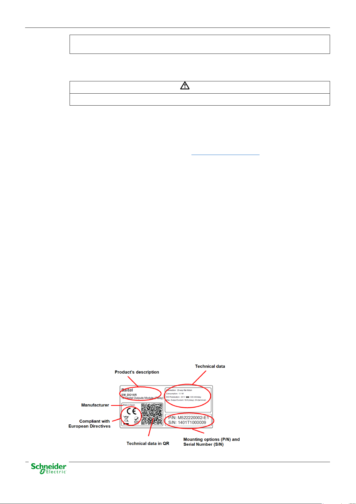
1.8 Technical Label
Each Saitel product includes a technical label with the following information:
Figure 3 – Technical label.
Pag 12
Page 13
User Manual – SM_SER 13/12/2019
NOTICE
On the “Technical data” zone, you can see relevant information about the input and output
voltage in the module. Any voltage greater than 50 V must be consider as a high voltage.
1.9 Packing and Unpacking
All Saitel modules are packaged separately in their own carton box and shipped inside outer
packaging. Use special care when unpacking the device. Don’t use force.
The design revision and manufacturing options can be determined using the P/N included in the
packaging label on packaging.
After unpacking the device, inspect it visually to be sure it is in proper mechanical condition.
If the product needs to be shipped, the original packaging must be used, including foams and the
carton box. If the original packaging is no longer available, make sure that the packaging used is
according to ISO 2248 specifications for a drop height 1 m.
1.10 Decommissioning and Disposal
SM_SER is marked with this symbol, it means that, at the end of its life cycle, you
mustn't dispose the product together with habitual residues. To avoid possible
damage to the environment or to the human health that represents the uncontrolled
elimination of residues, please follow the instructions in EOLI document for SM_SER.
Pag 13
Page 14

13/12/2019 User Manual – SM_SER
2 General Description of SM_SER
Pag 14
Page 15

User Manual – SM_SER 13/12/2019
Content
2 GENERAL DESCRIPTION OF SM_SER ............................................................... 14
2.1 SAITEL DP PLATFORM.......................................................................................... 16
2.2 SM_SER
2.3 I
NTERFACES ......................................................................................................... 18
FEATURES ............................................................................................ 17
Pag 15
Page 16
13/12/2019 User Manual – SM_SER
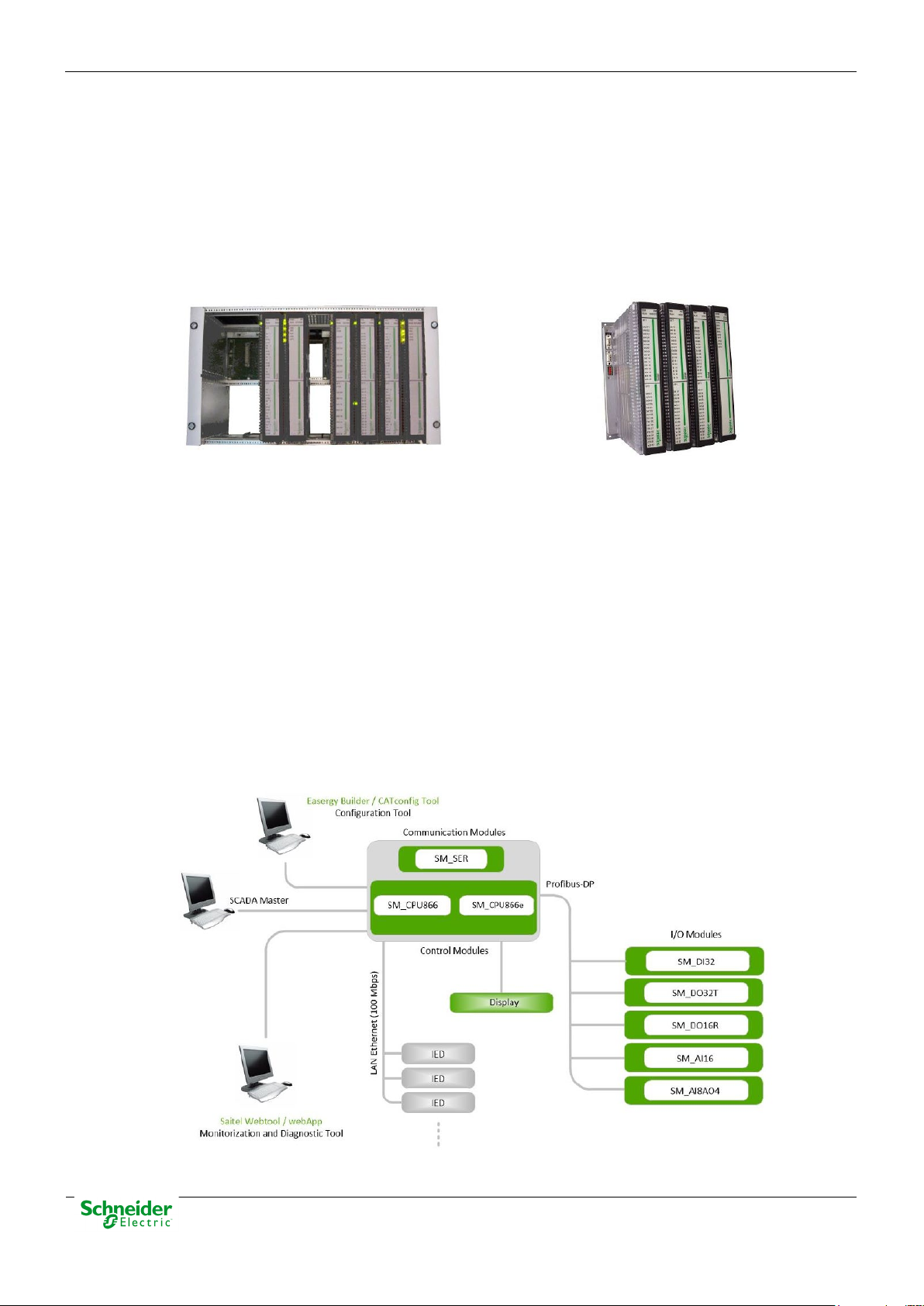
2.1 Saitel DP Platform
The Saitel DP platform is a complete set of devices provided by Schneider Electric for real-time
control applications and power line automation. It is a high-technology platform which gives a
solution to the business areas of Schneider Electric.
The following figures show a Saitel DP in chassis (left) and in backplane (right).
Figure 4 – Saitel DP in Chassis and Backplane
Saitel DP’s design has been optimized to meet the most demanding requirements of multiple
sectors:
• Cost-efficiency, minimum downtime, and compliance with electrical safety, electromagnetic
compatibility and environmental standards.
• Safety and reliability requirements for power, gas, water, residual water supply, etc.
• Centralized monitoring and control of geographically-distributed systems which support
hierarchical data acquisition and redundant networks.
• Local monitoring and control with data sharing capabilities of plant-distributed devices.
• Quick troubleshooting by means of programmable automation execution.
• One of the most remarkable features of Saitel DP is its modular design. All I/O, CPU, power
supply and communication modules have an identical format, sharing the same enclosure.
Figure 5 – Saitel DP architecture example
Pag 16
Page 17

User Manual – SM_SER 13/12/2019
2.2 SM_SER Features
The SM_SER is the serial communication module available in Saitel DP. It expands the control
module communication capability. This module is linked with the CPU module (SM_CPU866e)
through a bidirectional high-speed channel.
The SM_SER module communicates with the CPU module through the internal bus, at a
transmission rate of up to 1.5 Mbps. The multiplexing operation allows transfers the message
streams bidirectional from input channels and its signals.
The communication protocol between the SM_SER module and CPU module follows a masterslave (poll-response) structure, in which the master is the CPU module and the slave are the
different SM_SER modules which are installed.
Figure 6 – Saitel DP architecture example
Controller Block
The SM_SER module supports:
• A controller block
• A communication channels block
• An indication block
The controller block supports the following functions:
• Parameterization and control of the communication blocks.:
o Asynchronous communication.
o Configurable transmission/reception.
o Configurable transmission rate up to 38,400 bps.
o Configurable stream (number of bits, start, stop and parity bit).
o RTS/CTS flow control.
o Transmission/reception of complete streams.
Pag 17
Page 18

13/12/2019 User Manual – SM_SER
• Block indication update with the new block module information.
• Communication bus Interface to connect with the CPU.
Controller Channels Block
Each module includes eight completely configurable communication channels with the following
features:
• Input protection against electromagnetic disturbances.
• Galvanic isolation through iCouplers® avoiding the use of optocouplers.
• 6 signals for each channel: TX, RX, RTS, CTS, DTR and DSR.
• RS-232 / RS-485 / RS-422 signal levels. All channels are configurable as RS-232, RS-485 or
RS-422.
2.3 Interfaces
The module integrates 8 channels supporting RS-232, RS-485 or RS-422 communications:
The pin numbers in the RJ-45 connector are the same in all cases. SM_SER module does not
include LED indicators in the connector base. All connectors are RJ-45 type.
Pag 18
Page 19

User Manual – SM_SER 13/12/2019
3 Physical Mounting & Installing
Pag 19
Page 20

13/12/2019 User Manual – SM_SER
Content
3 PHYSICAL MOUNTING & INSTALLING ............................................................... 19
3.1 INSTALLATION ...................................................................................................... 21
3.1.1 H
3.1.2 M
3.1.3 P
3.1.4 M
3.1.5 C
3.2 W
3.2.1 R
3.2.2 W
3.2.3 W
3.2.4 W
3.2.5 T
3.3 LED
ANDING ...................................................................................................... 21
ODULE LOCATION WITHIN THE CHASSIS OR BACKPLANE ................................ 21
OWER SUPPLY REQUIREMENTS ................................................................... 21
OUNTING PROCEDURE ................................................................................ 22
ONFIGURATION SWITCHES ........................................................................... 22
IRING SM_SER................................................................................................. 24
ECOMMENDATION FOR EMC ........................................................................ 24
IRING RS-485 ............................................................................................ 24
IRING RS-422 ............................................................................................ 25
IRING RS-232 ............................................................................................ 25
ERMINATION RESISTOR (RS-485 AND RS-422) ............................................. 25
INDICATORS ................................................................................................. 27
Pag 20
Page 21

User Manual – SM_SER 13/12/2019
WARNING
The voltage input for the backplane is 5.4 ± 0.2 VDC. The external voltage input isn't protected
WARNING
The electrostatic discharges may damage semi-conducive devices within the module, if the
3.1 Installation
3.1.1 Handing
connector pins are in contact with the backplane.
Please note the following precautions to avoid electrostatic damages:
• You should handle the module from the front side, as far as possible from the backplane
connectors.
• You should never touch the pins of the backplane connector.
• You should keep the module in its antistatic bag or packaging box, when unused.
3.1.2 Module Location within the Chassis or Backplane
All modules must be installed always in vertical position.
All SM_SER modules in the RTU must be installed in the first backplane. Communication data can
be expanded to others backplanes. Then, the maximum number of SM_SER modules connected to
a CPU is 8.
When using a power supply such as the SM_PS or SM_PS40 module, it must be located in the
position 1 (slot1 left-hand side). In redundant-power supply configurations, there must be two
reserved positions for the two power supply modules. These positions must be 1 and 2.
Remaining modules can be located in any position (slot) within the chassis.
Figure 7 – Backplane positions
Modules must be grouped to minimize the adverse effects caused by noise and heat, therefore,
modules, and more specifically the CPU modules, must be placed as far as possible from the
modules which operate at alternating currents or high currents.
If the system has redundant CPUs, both control modules must be put together in the backplane
3.1.3 Power Supply Requirements
against overvoltage nor polarity inversion, so an incorrect wiring or an incorrect adjustment of
the supply voltage could damage electronic.
Pag 21
Page 22

13/12/2019 User Manual – SM_SER
The SM_PS and SM_PS40 modules (power-supplies) are scalable to supply power to the modules
connected to the backplane, as required. When using auxiliary power supplies, it is necessary to
scale them depending on the installed Saitel DP modules.
The consumption of all modules will be added plus a safety margin (between 20% and 50% of the
full power). The power supply efficiency typically, 70 - 90% shall also be considered, to protect the
chassis and power supply from overloading.
The maximum power requirement for each SM_SER module is: 3.9 W.
3.1.4 Mounting Procedure
Saitel DP modules can be installed in a 19-inch chassis (SM_CHX) or a backplane SM_BPX.
When SM_BPX module is used, some problems with the installation of the modules are detected.
On the other hand, there are some configurations working correctly but the modules haven´t been
mounted correctly. This situation produces a mechanical instability and might cause serious
problems.
Following picture shows three modules inserted on the backplane. One of them has been inserted
incorrectly in spite of it is functional totally.
Figure 8 – Saitel DP module inserted incorrectly
Consult application note
• How the user should mount a Saitel DP module on a panel-mounted backplane.
• How the user should verify the installation.
• Actions that the user should do when an incorrect mounting is detected.
To mount the module in the chassis or backplane, please follow the following instructions:
• Switch off the power supply.
• Mount the module at the desired position, and if you are using a backplane mounting,
verify that the rear rails are properly mounted using the pre-drilled holes on the
backplane.
• Firmly press the module to assure the connector fits in the connector properly. Check
whether the module is correctly mounted to the backplane base.
• Fix the module using the screw located at the top.
FTE-AN010-F700 for more information about:
3.1.5 Configuration Switches
The module’s identification and Profibus communication speed can be set using the microswitches
on the module's rear panel. Switches 1 to 4 are used to configure the multiplexer's address. The
position allocation is shown in the following table:
Pag 22
Page 23

User Manual – SM_SER 13/12/2019
NOTICE
For optimal system performance is recommended to set the Profibus rate to 1.5
Table 2 – Addressing the SM_SER module
Position 4 Position 3 Position 2 Position 1 Address
OFF OFF OFF ON 1
OFF OFF ON OFF 2
OFF OFF ON ON 3
OFF ON OFF OFF 4
OFF ON OFF ON 5
OFF ON ON OFF 6
OFF ON ON ON 7
ON OFF OFF OFF 8
The Profibus communication speed must be the same for all Saitel DP modules, which is
determined by the speed of the master, configured by software, in the control module. The speed is
set using microswitches 9, 10 and 11 as shown in the following table:
Table 3 – Configuration switches
Position 11 Position 10 Position 9 Profibus Rate
OFF OFF OFF 19.2 kbaud
OFF OFF ON 93.75 kbaud
OFF ON OFF 187.5 kbaud
OFF ON ON 500 kbaud
ON OFF OFF 1.5 Mbaud
ON OFF ON Not available
ON ON OFF Not available
ON ON ON Not available
Mbaud. Microswitches 8 and 12 are reserved and must be set to OFF.
Pag 23
Page 24

13/12/2019 User Manual – SM_SER
WARNING
Particular care must be taken when connecting the shielding to make sure it is effective.
Connecting NOT equipotential devices could be hazardous for persons and equipment.
3.2 Wiring SM_SER
The module integrates 8 channels supporting RS-232, RS-485 or RS-422 communications:
The pin numbers in the RJ-45 connector are the same in all cases. SM_SER module does not
include LED indicators in the connector base. All connectors are RJ-45 type.
3.2.1 Recommendation for EMC
In order to avoid EMC disturbances, the following considerations must be follow.
The communication bus can be installed using 2-wire communication or 4-wire communication. In
order to increase the immunity to electromagnetic interference (EMC), the use of a shielded twisted
pair is recommended.
The shield connection depends on the equipotentiality between the connected devices:
• Guaranteed equipotentiality: Both devices are connected to a ground system, so that the
same potential level is guaranteed. The shield must be connected at both ends.
• Limited equipotentiality: Both devices are connected to ground but not to the same ground
system. To limit the difference of potential that can be produced among them a cable with the
appropriate cross-section will be installed between the grounding of both. The shield must be
connected at one end.
• No guaranteed equipotentiality: Ground connection of both devices can’t be guaranteed
(both devices must be connected to a ground system). Copper mustn’t be used in this case.
3.2.2 Wiring RS-485
For RS-485 the pairs are shielded individually or all together by a copper braid. The
recommendations for the cable are:
• Resistance: < 100 Ω/km.
2
• Section: 0.22 mm
• Characteristic impedance: 120 Ω.
• Maximum length: 1200 m.
All channels can be configured as RS-485 half-duplex or full-duplex.
Table 4 – RS-485 port pinout
(24 AWG)
DANGER
Pin Description I/O
1 Rx (-) B I/O
3 Tx (+) Y I/O
4, 5 GND
6 Rx (+) A I/O
8 Tx (-) Z I/O
Pag 24
Page 25

User Manual – SM_SER 13/12/2019
The cabling for a half-duplex communication is:
• Join wires 1 and 8 (Rx(-) / Tx(-), B/Z or Negative (-)).
• Join wires 3 and 6 (Tx(+) / Rx(+), A/Y or Positive (+)).
• Join wires 4 and 5 to GND.
3.2.3 Wiring RS-422
For RS-422 the pairs must be shielded individually. The recommendations for the cable are:
• Resistance: < 100 Ω/km.
• Section: 0.22 mm2 (24 AWG)
• Characteristic impedance: 100 Ω.
• Maximum length: 1200 m.
All channels can be configured as RS-422.
Table 5 – RS-422 port pinout
Pin Description I/O
1 Rx (-) I
3 Tx (+) O
4, 5 GND
6 Rx (+) I
8 Tx (-) O
3.2.4 Wiring RS-232
The 8 communication channels can be configured as full RS-232 with galvanic isolation.
Table 6 – RS-232 port pinout
Pin Description I/O
1 /CTS I
2 /DTR O
3 Data transmission O
4
5
6 Data reception I
GND
7 /DCD I
8 /RTS O
3.2.5 Termination Resistor (RS-485 and RS-422)
In a communication bus (RS-485 or RS-422) the devices installed on the ends of the bus must
include a termination resistor. Usually, this is the case of the SM_SER module where its
communications ports exclude the possibility of installing this resistance.
Pag 25
Page 26

13/12/2019 User Manual – SM_SER
NOTICE
It is important to note that for each bus, two and only two devices must function as
NOTICE
These figures should be understood as an example. You can use some other
For each communications port that works as end of the bus, a terminal with termination resistors
(120 to 150 Ω) for both reception and transmission channels must be installed.
termination of the bus.
There are two recommended models for these auxiliary terminal (both by Phoenix Contact):
Figure 9 – FL-PP-RJ45-SC and VIP-3/PT/RJ45
For example, the following figure shows how you can use a 5-pin terminal for RS-422 and for RS485 in full-duplex communications:
Figure 10 – Termination resistor in full-duplex communications
For RS-485, using half-duplex communications, a 3-pin terminal must be used:
Figure 11 – Termination resistor in half-duplex communications
mechanism that provides you with the same functionality.
To connect the SM_SER port with the auxiliary terminal, if the bus is RS-422 or full-duplex RS-485,
the cable to be used is shown in the following figure:
Figure 12 – Cable for connection SM_SER-Auxiliary terminal in full-duplex communications
Pag 26
Page 27

User Manual – SM_SER 13/12/2019
Figure 13 – Cable for connection SM_SER-Auxiliary terminal in half-duplex communications
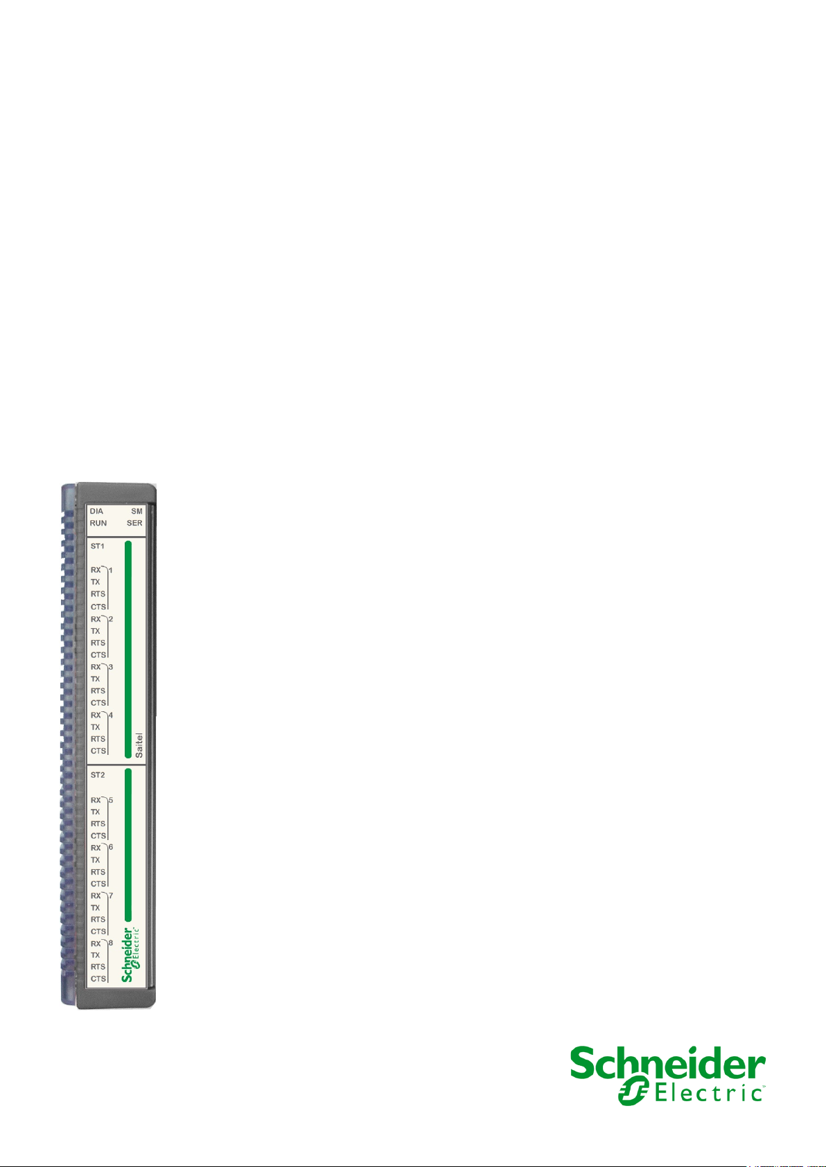
3.3 LED Indicators
The following led indicators are available in a SM_SER module:
Figure 14 – LED indicators
• General Diagnostics (DIA)
• Operation status (RUN)
• One diagnostic LED for each block of 4 communication channels (ST1/ST2)
• Thirty-two indications for the channel signals. Four indications for each channel to display the
“Transmission” status (TX1-TX8), “Reception” (RX1-RX8), “Request to Send “(RTS1-RTS8)
and “Clear to Send” (CTS1-CTS8).
Pag 27
Page 28

13/12/2019 User Manual – SM_SER
The module is configured and communication with
Wrong configuration. It is probably that the module
Wrong configuration. It is probably that the module
On when Request To Send (RTS) or Clear To Send
The firmware doesn’t work fine. It is necessary to
Hardware malfunction on the block x. (2)
Receiving data.
Transmitting data.
SM_SER provides the following information to the operator:
Table 7 – Led indicators meaning
DIA RUN STx RXx TXx RTSx CTSx Description
the CPU.
has assigned the address 0. (2)
has assigned an address greater than 8. (1)
(CTS) signals are activated. The channel has to
been set with ENABLE for “RTS Control”. If the
channel has been set as TOGGLE (or AUTO for
revision DA and later), these leds are only on if
there is transmission/reception. These leds are off
for any other situation.
load the software again. (2)
Hardware malfunction. (2)
The actions to be taken are:
• (1) If the module address does not match with any configured address, this module will not be
able to exchange data with the control unit. Check if the module address is correct. The
module may also be switched off.
• (2) Check the wiring, if correct, contact the support service.
Pag 28
Page 29

User Manual – SM_SER 13/12/2019
4 Maintenance & Configuration
Pag 29
Page 30

13/12/2019 User Manual – SM_SER
Content
4 MAINTENANCE & CONFIGURATION ................................................................... 29
4.1 CONFIGURATION OF THE BACKPLANE .................................................................... 31
4.2 SM_SER
4.2.1 SM_SER
4.3 M
AINTENANCE OF MODULE VIA WEB .................................................................... 36
4.3.1
4.3.2 U
4.3.3 U
4.4 F
4.5 C
IRMWARE UPGRADE ........................................................................................... 40
HANNELS SUPERVISION ...................................................................................... 41
CONFIGURATION ................................................................................... 33
CHANNEL ...................................................................................... 33
WEBAPP VS WEBTOOL ................................................................................... 36
SING WEBAPP ............................................................................................. 37
SING WEBTOOL .......................................................................................... 39
Pag 30
Page 31

User Manual – SM_SER 13/12/2019
4.1 Configuration of the Backplane
NOTICE
To perform the operations described in this chapter, the user must be familiar with the
configuration tool. Otherwise, please consult the user manual of Easergy Builder.
In the Workspace of Easergy Builder, create a new RTU using button or pressing right button
of the mouse in an empty area of the RTUs tree:
Figure 15 – Adding new RTU
Pressing button next to the picture, you can add, remove or change the I/O modules included on
the default configuration.
Figure 16 – Add, remove or change I/O modules
Each I/O module is allocated to a unique and identifying number in the bus (Profibus address). This
number is assigned using the switches available in the rear panel of the module.
The CPU needs to know the address and the types of I/O modules installed in the bus in order to
initialize and switch to data acquisition mode properly.
All examples in this chapter are made using an SM_CPU866e CPU but all operation is similar for
SM_CPU866.
Figure 17 – Acquisition modules in the default configuration
Pag 31
Page 32

13/12/2019 User Manual – SM_SER
This window allows:
• Add or remove module in the backplane. Use button to add new modules and to
remove a module.
Figure 18 – Adding one or several I/O modules.
• The address for each module is displayed under its picture and it can be changed using the
button . The address for each module must be the same that is indicated with its rear
switches.
• Use button to configure the time parameters of the polling and digital filtering:
Figure 19 – Configuration parameters.
To create a new configuration, select your RTU in the tree and pulse right button of the mouse or
use the button .
Figure 20 – Add configuration.
If the field "Create acquisition points defined in the RTU" is marked, all points of the local
acquisition of the acquisition blocks included in the default acquisition configuration associated with
the RTU will be included in coreDb.
For example, if a SM_CPU866e has a backplane with a SM_DO16R module, if "Create
acquisition points defined in the RTU", following points are generated:
Pag 32
Page 33

User Manual – SM_SER 13/12/2019
• 16 digital outputs in the Command table.
• SM_DO16R supervision points in the Status table.
• System supervision points by default in the Status and Analog table: WARN_PS1, FAIL_RTU,
DOING_WELL….
At the end of the operation, the new configuration will appear in the RTUs tree. Double-click on it
and the Configuration mode is activated.
Figure 21 – Configuration mode.
Double click on the laq Device and the backplane configuration window allows to modify the
acquisition configuration.
Selecting the module SM_DO16R, you can configure each field signal
Figure 22 – Configuration mode.
Other buttons in this window are explained in the user manual of Easergy Builder.
4.2 SM_SER Configuration
4.2.1 SM_SER Channel
The ports used to communicate with field devices are configured as communication channels. They
can be configured in the Channels tab of the configuration mode of Easergy Builder. The number
and type of these channels depends on the type of CPU and communication modules installed in the
RTU.
Pag 33
Page 34

13/12/2019 User Manual – SM_SER
Figure 23 – SM_SER Channel Architecture
For example, this figure shows an RTU with a 866e and an SM_SER module. The “Channel
Architecture” zone displays all channels and links (channel associations) which are defined.
• Channel1 and Channel2: COM1 and COM2 (HU_A)
• Channel3 and Channel4: RS-485 and RS-422 (SM_SER)
Using buttons in the toolbar, you can:
• Add a new channel or link.
• Delete a channel or link.
• Modify the configuration of a channel or link
The following figure shows the configuration panel for ASYNC channel:
Figure 24 – Channel Setup
Where:
• Name: Identifying name
• Description: Description
Pag 34
Page 35

User Manual – SM_SER 13/12/2019
• Type: Channel type depending on the implemented communication protocol. There are three
types:
o TCP
o UDP
o ASYNC (RS-232, RS-485 or RS-422 serial communication)
• Specific Parameters: Reserved, this box mustn’t be checked
• Channel: The physical port that will be used for this channel. The list of physical channels
available depends on the CPU type:
o SM_CPU866 and SM_CPU866e: COM1, COM2, COM3, COM4 and SM_SERx-
COMy. Only ports of the SM_SER configured will be available.
o HU_A and HU_AF: COM1, COM2, RS-485 and AB_SERx-COMy. Only ports of the
AB_SER configured will be available.
o HU_B: COM1 and COM2
o HU_BI: COM1/RS-485. Only one of these ports can be used at the same time
o HU 250: RS-485, K7 RS SLOT(1) and K7 RS SLOT(2). K7 RS SLOT 1 and 2 will be
available or not depending on the configuration of the slots 1 and 2
• Baudrate: To specify the communication speed. The speed ranges between 300 and 256000
bps
• Protocol: It defines the asynchronous protocol which will be used. The available protocols are
RS-232, RS-485 and RS-422. RS-485 allows 2 or 4-wire communications.
• Parity, Stop bit, Data bits: To configure communication parameters
• RS-485 / RS-422:
o Termination resistor
o Polarization
• Modem Control: These parameters allow configuring the signals for modem control in the
communication ports. Not all values are available for each CPU
o DTR Control: Flow control
ENABLE: DTR at high logical level (1)
DISABLE: DTR at low logical level (0)
TOGGLE (only available for K7 modem): DTR control depends on the
parameter “DTR - RTS delay”.
o RTS Control: To configure the RTS output
DISABLE. Disables the use of the RTS signal
ENABLE: It enables the RTS signal, and keeps it active.
AUTO: The RTS signal timing will be defined automatically.
o CD Control:
o DSR Control:
TOGGLE: It allows defining timing for RTS signal.
ENABLE: CD at high logical level (1).
DISABLE: CD at low logical level (0).
ENABLE: DSR at high logical level (1).
Pag 35
Page 36

13/12/2019 User Manual – SM_SER
NOTICE
NOTICE
webApp has been designed to work only with the Cybersecurity brick. At now, it can be only
DISABLE: DSR at low logical level (0).
o Time Setup: The time setup when DTR is configured as TOGGLE
Delay before transmission: Elapsed time from the data transmission is
ready and activation of the RTS
DTR – RTS delay: Timeout before establish the RTS signal when DTR has
been activated
Timeout CTS: Standby time from the activation of the RTS to the activation
of the CTS. If the CTS value is zero, it means that the transmission will be
done regardless of CTS value. For non-zero values, channel transmission
is controlled by the CTS; if the time defined in this attribute elapses without
a CTS activation, then the package pending to be sent is discarded
RTS(or CTS) message delay: Elapsed time from the activation of the CTS
to data transmission
Message – RTS delay: time from the end of the data transmission to RTS
deactivation.
For 2-wire RS-485 communications, it is very often necessary to set the RTS control to TOGGLE,
and define all times to 0 ms. Thus, reception while transmitting is disabled (to avoid echo).
4.3 Maintenance of Module via WEB
4.3.1 webApp vs webTool
webApp and webTool are remote user interfaces for consulting, monitoring and maintenance tasks.
Once the username and password have been entered, you can access to the main window and,
depending on the web tool, several sections are available.
used with SM_CPU866e V1. SM_CPU866e V0 and SM_CPU866 use webTool.
When use webApp, the following message is shown previously to access the tool:
Figure 25 – Disclaimer information
Please, read this information and take it into account.
In this manual, only the information about SM_SER is shown. For more information about webApp
and webTool, please, consult the user manual for each one.
Pag 36
Page 37

User Manual – SM_SER 13/12/2019
4.3.2 Using webApp
Saitel webApp includes an access management allowing to control users who can login in the tool.
To access webApp, write https://< CPU IP address> in the navigation address bar, where <CPU
IP address> must be changed for the correct IP address:
Figure 26 – Access screen.
Write the Username and Password in order to access the webApp’s main window:
This screen contains 5 menus:
• Home
• Monitoring & Control
Home
• Diagnostic
• Maintenance
• Settings
Select Home in the main toolbar and the following information is shown:
Figure 27 – Home tab
Some of this information can be filled in by the user.
• Device Information. It is possible to add the names of the operators who have used or
configured the equipment or a specific custom note that can be viewed each time a connection
is established to this RTU. This information can be changed using button “Edit”, next to “Device
information”.
Pag 37
Page 38

13/12/2019 User Manual – SM_SER
• Location. The GPS coordinates for the RTU location (place, latitude, longitude, and altitude)
should be entered here by the installer. Location is not set automatically. The image must be
included manually by clicking button on the map.
• Image associated to the RTU. It could be useful to include a location map corresponding to the
GPS coordinates. Use button on the graphic zone to do it.
• Notes. This zone allows the user to include notes that are shown to other users. Use button
• Factory information: This zone shows the manufacturer, model and the version of the
software loaded on the HU module. Using button next to the text “Factory Information”, it is
also possible to include an image of the particular RTU or CPU for identification purposes.
Monitoring and Control
This menu is used to monitor and control the information regarding to system status and coreDb
points.
Select “Monitoring & control System information” and the following information the system is
displayed or not depending on whether the corresponding monitoring point was included or not in
coreDb. In the following image, for each data, the supervision point that must be included in coreDb
is indicated in a blue square.
Figure 28 – Monitoring and control view - System information
too add new notes.
On the other hand, the “Monitoring and control Data” allows to monitor the information of each
coreDb table:
• Status page: For viewing the status of the digital data
• Command page: For sending change of state commands based on the digital data.
• Analog page: For viewing measurement values.
• Setpoint page: For forcing parameter values.
Pag 38
Page 39

User Manual – SM_SER 13/12/2019
Diagnostic
• In the menu Diagnostic you can find a Trace tab. The channels configured with Easergy
Builder can be monitored in Trace tab. The user can choose the channel to monitoring and it
click in the field “Show selected traces”.
Figure 29 – Diagnostic View
4.3.3 Using webTool
Saitel webTool is used for maintenance and monitoring of Saitel RTUs which are supplied with the
baseline software platform but without Cybersecurity brick, SM_CPU866 and SM_CPU866e V0.
Like webApp, webTool allows to monitor and to change the real-time value and associated quality
information for each coreDb signal.
Saitel webTool includes an access control allowing to identify and manage the users who are able
to connect.
Please, write https://< CPU IP address> in the navigation address. If the browser was correctly
configured and the CPU is connected to the PC via ethernet, the login window will prompt:
Figure 30 – Saitel webTool login window.
Once the username and the password are introduced in the login window, the main workspace is
displayed:
Figure 31 – Initial screen of Saitel webTool
Pag 39
Page 40

13/12/2019 User Manual – SM_SER
This window shows:
• User who is logged in the session (user target in the previous picture).
• The button “Exit” allows to close the current session.
• Active language for the session. Use the pull-down field “Language” to change it.
• The main menu is located on the left side of the window. It allows you to access all information
of the RTU:
• Information: General information about the CPU configuration.
• Monitoring: Gives access to the coreDb tables and the values for each register and field.
• Bins: Gives access to the devices that have been configured in the RTU.
• Network configuration: Gives information about the physical devices and rooters.
4.4 Firmware Upgrade
Once the backplane is configured, the CPU module (866 or 866e) already knows the type of
acquisition blocks that are been installed and their corresponding addresses.
To update the software of the SM_SER module, you need:
• A console connection with the CPU.
• SM_SER module must be correctly addressed and working fine in the backplane (LED Run
must be blinking).
• SM_SER.bin file with the new version. This file must be available in the flash folder of the CPU.
If not, you can contact Schneider Electric in order to ask for it. Use an SFTP client and transfer
this binary file into the CPU flash folder.
The console tool can be executed using any commercial tool for serial or SSH connection. In this
manual, PuTTy software is used.
Open a serial connection as follow:
Figure 32 – PuTTY configuration
SSH connection via Ethernet can be used too. More information about the console use in the CPU
user manual. In the following picture, CPU866e is used:
Pag 40
Page 41

User Manual – SM_SER 13/12/2019
NOTICE
If the baseline includes the cybersecurity brick, you need to login in the console with Installer.
Module
File
Command
NOTICE
Console commands are case-sensitive, and quotation marks must be included.
Figure 33 – SSH connection
No other user has permissions to execute this operation. Please, consult the CPU user manual
for more information.
If the file SM_SER.bin is available in the flash folder, use one of the following commands to
upgrade the software of SM_SER modules:
Table 8 – Upgrading SM_SER software.
SM_SER SM_SER.bin MUX_upgrade <Module nº>, where <Module nº> could
After running the command, the console will show some messages indicating the process status.
Finally, if no problem is found, we will have updated the firmware of the modules.
4.5 Channels Supervision
SM_SER allows monitoring its channels using the COM8 port.
In order to use this monitoring tool, the following procedure should be as follow:
1. The switch 12 of the SM_SER module must be ON
be a specific number between 1 and 8. It corresponds
with the address of the SM_SER module to be updated.
2. Connect the PC with the module using the COM8 port by default. This port can be changed to
channel x using command SMx (more information later in this paragraph).
3. Open a terminal window similar to the console tool.
A prompt for the SM_SER module should be shown, for example “SM_SER>”.
Execute the command “help” and you can see a help with available commands:
Pag 41
Page 42

13/12/2019 User Manual – SM_SER
Figure 34 – SM_SER Main Menu
• HE: Show this menu.
• SNx: Start monitoring (sniff) for channel x, where x is from 1 to 8.
• CSx: Show configuration of channel x. For example:
Figure 35 – Channel Configuration
• SMx: Change the monitor channel to channel x. This operation must be confirmed before
channel x is the new channel monitoring.
• SV: Show the software version installed in the module (SM_SER).
• RB: Reboot
Pag 42
Page 43

User Manual – SM_SER 13/12/2019
5 Technical Specification Table
Pag 43
Page 44

13/12/2019 User Manual – SM_SER
Hardware Specifications
Number of channels.
8
Isolation between channels
2 kV
RMS
Signal level
RS-232 / RS-485 / RS-422
Signals
Rx - Tx - RTS - CTS - DTR - DSR
Dimensions
245 x 170 x 45 mm
Interfaces
8 ports
RJ-45 connector
Resistance < 100 Ω/km
Wire: 0.22 mm2 (24 AWG)
Impedance: 120 Ω
Max wiring length: 1200 m
Half duplex / Full duplex
Resistance < 100 Ω/km
Wire: 0.22 mm2 (24 AWG)
Impedance: 100 Ω
Max wiring length: 1200 m
Software
Configurable per channel
Up to 38400 baud
Transmission / Reception
By complete streams
CE Mark
LVD – Low Voltage Directive
EMC – Electromagnetic Compatibility
Substances
ErP – Eco-Design
Equipment
IEC 61000-6-2
IEC 61000-6-4
Consumption 3.4 W (Using 8 channels)
Weight 677 g
Field connection
RS-485 connection
RS-422 connection
Transmission features
Transmission rate
Standards, Directives and
harmonized norms.
RoHS 2 – Restriction of Hazardous
Directive 2006/95/CE
Directive 2004/108/CE
Directive 2011/65/EU, according to royal legislative
decree (RD) 219/2013
Directive 2010/30/EU according to RD 187/2011
EMC tests according to Immunity for equipment used in power station and substation environment
WEEE – Waste Electrical and Electronic
Emission standard for industrial environments
Directive 2012/19/UE according to RD 110/2015
Pag 44
Page 45

User Manual – SM_SER 13/12/2019
CE Mark
EN 55011
ANSI C37.1)
EN 61000-3-3
ANSI C37.1
EN 61000-3-2, IEC 61000-4-7
ANSI C37.1
ANSI C37.90.2
EN 61000-4-4
EN 61000-4-5
±2 kV in
(Level 3).
EN 61000-4-6
EN 61000-4-8
EN 61000-4-9
0% voltage supply, 20 ms (Level 0):
Voltage falls of >95% during 5000 ms
IEC 60255-22-1 (EN 61000-4-12).
ANSI C37.90.1
EN 61010-1 and IEC 60255-1
IEC 60255-5
IEC 60255-5
EN 60068-2-1:2007
EN 60068-2-2:2007
IEC 60068-2-30
Emission EMC tests Radiated emissions
Radiated emission
Conducted emissions
Conducted emission
Harmonics limits
Immunity EMC tests Radiated, radio-frequency
Radiated, radio-frequency
EFT burst
Surge
Common mode RF
From 30 MHz to 1000 MHz (Class A).
From 150 kHz to 30 MHz (Class A).
At 1 m from 10 kHz to 1000 MHz
Compliant with voltage fluctuations and flicker
<1.5% Vpp voltage supply
from 1 kHz to 10 kHz.
Class A
1 V/m/MHz from 10 kHz to 25 MHz (AM)
35 V/m/MHz from 25 MHz to 1000 MHz (FM)
±4 kV/5 kHz
AC or DC power and I/O lines (Level 4).
AC or DC power and ±1 kV in I/O lines
10 V
from 150 kHz to 80 MHz (Level 3).
RMS
Magnetic field
Pulse magnetic field
Voltage drops and power faults
EN 61000-4-11
Oscillatory wave
Oscillatory wave
Electrical Safety General requirements
Dielectric rigidity
Impulse voltage
Envirnmental tests Cold
30 A/m at 50 Hz (Level 4)
10 A/m at 50 Hz (Level 3)
Special level:
Voltage falls of 30% during 10 ms
Voltage falls of 60% during 100 ms
Class III, ±2.5 kV/5 kHz (Level 3).
1 MHz at ±2.5kV
Compliant with all the standard's requirements
Isolation >100 MΩ, 2 kV
±5 kV in AC or DC power
±4 kV in I/O lines
-40ºC during 16h (Cold start)
RMS
Dry heat
Cyclic humid heat
+55 ºC during 16h
From 25 ºC to 55 ºC
with 95% RH, 2 cycles of 24 h.
Pag 45
Page 46

13/12/2019 User Manual – SM_SER
Ordering Options
Pag 46
Page 47

User Manual – SM_SER 13/12/2019
Glossary
A
A: Ampere.
AC: Alternate Current.
AWG: American Wire Gauge.
C
ºC: Celsius degree.
COM: Communication port.
CPU: Central Processing Unit.
D
DC: Direct Current.
DI: Digital Input.
DO: Digital Output.
E
EMC: ElectroMagnetic Compatibility.
G
g: Gram.
GPS: Global Positioning System.
H
Hz: Hertz.
I
IED: Intelligent Electronic Device.
I/O: Input / Output.
ISO 9001: International standard for Quality Systems.
K
kHz: Kilohertz.
L
LED: Light Emitting Diode.
Pag 47
Page 48

13/12/2019 User Manual – SM_SER
M
mA: Milliampere.
MHz: Megahertz.
m: Meter.
mm: Millimeter.
ms: Millisecond.
N
N/A: Non-Application.
P
PC: Personal Computer.
PS: Power Supply.
R
RTU: Remote Terminal Unit.
S
s: Second.
SFTP: Secure File Transfer Protocol.
SM_DO16R: Digital Outputs to Relay module.
SM_PS: Power supply module.
SM_PS40: Power supply module.
SM_SER: Communication module for expansion.
V
VAC: Volt of Alternate Current.
: Volt of Direct Current.
V
DC
W
W: Watt.
Pag 48
Page 49

User Manual – SM_SER 13/12/2019
Index of Figures
Figure 1 – Barrier of protection for elements with dangerous voltages. ....................................................................... 9
Figure 2 – Yellow and Green cable for earthing. ........................................................................................................ 10
Figure 3 – Technical label. .......................................................................................................................................... 12
Figure 4 – Saitel DP in Chassis and Backplane ......................................................................................................... 16
Figure 5 – Saitel DP architecture example ................................................................................................................. 16
Figure 6 – Saitel DP architecture example ................................................................................................................. 17
Figure 7 – Backplane positions ................................................................................................................................... 21
Figure 8 – Saitel DP module inserted incorrectly ....................................................................................................... 22
Figure 9 – FL-PP-RJ45-SC and VIP-3/PT/RJ45 ........................................................................................................ 26
Figure 10 – Termination resistor in full-duplex communications ................................................................................ 26
Figure 11 – Termination resistor in half-duplex communications ............................................................................... 26
Figure 12 – Cable for connection SM_SER-Auxiliary terminal in full-duplex communications .................................. 26
Figure 13 – Cable for connection SM_SER-Auxiliary terminal in half-duplex communications ................................. 27
Figure 14 – LED indicators ......................................................................................................................................... 27
Figure 15 – Adding new RTU ..................................................................................................................................... 31
Figure 16 – Add, remove or change I/O modules ....................................................................................................... 31
Figure 17 – Acquisition modules in the default configuration ..................................................................................... 31
Figure 18 – Adding one or several I/O modules. ........................................................................................................ 32
Figure 19 – Configuration parameters. ....................................................................................................................... 32
Figure 20 – Add configuration..................................................................................................................................... 32
Figure 21 – Configuration mode. ................................................................................................................................ 33
Figure 22 – Configuration mode. ................................................................................................................................ 33
Figure 23 – SM_SER Channel Architecture ............................................................................................................... 34
Figure 24 – Channel Setup ......................................................................................................................................... 34
Figure 25 – Disclaimer information ............................................................................................................................. 36
Figure 26 – Access screen. ........................................................................................................................................ 37
Figure 27 – Home tab ................................................................................................................................................. 37
Figure 28 – Monitoring and control view - System information .................................................................................. 38
Figure 29 – Diagnostic View ....................................................................................................................................... 39
Figure 30 – Saitel webTool login window. .................................................................................................................. 39
Figure 31 – Initial screen of Saitel webTool ................................................................................................................ 39
Figure 32 – PuTTY configuration ................................................................................................................................ 40
Figure 33 – SSH connection ....................................................................................................................................... 41
Figure 34 – SM_SER Main Menu ............................................................................................................................... 42
Figure 35 – Channel Configuration ............................................................................................................................. 42
Pag 49
Page 50

13/12/2019 User Manual – SM_SER
Index of Tables
Table 1 – Symbols ........................................................................................................................................................ 8
Table 2 – Addressing the SM_SER module ............................................................................................................... 23
Table 3 – Configuration switches................................................................................................................................ 23
Table 4 – RS-485 port pinout...................................................................................................................................... 24
Table 5 – RS-422 port pinout...................................................................................................................................... 25
Table 6 – RS-232 port pinout...................................................................................................................................... 25
Table 7 – Led indicators meaning.............................................................................................................................. 28
Table 8 – Upgrading SM_SER software. ................................................................................................................... 41
Pag 50
Page 51

User Manual – SM_SER
13/12/2019
P
rinted in:
Monday, February 17, 2020
S
chneider Electric
C/ Charles Darwin s/n
Parque Científico y Tecnológico de la Cartuja
Seville, Spain
©
2020 All rights reserved. The information contained in this document is
confidential and is owned by Schneider Electric. It cannot be copied or distributed
in any way, unless there is express written authorization by Schneider Electric.
Although this information was verified at the time of publication, may be subject to change without notice.
SE-M5
81-USR-02 02/2020
Pag 51
 Loading...