


M580
PHA83350 11/2020
M580
BMENUA0100 OPC UA Embedded
Module
Installation and Configuration Guide
Original instructions
11/2020
PHA83350.02
www.schneider-electric.com

The information provided in this documentation contains general descriptions and/or technical
characteristics of the performance of the products contained herein. This documentation is not
intended as a substitute for and is not to be used for determining suitability or reliability of these
products for specific user applications. It is the duty of any such user or integrator to perform the
appropriate and complete risk analysis, evaluation and testing of the products with respect to the
relevant specific application or use thereof. Neither Schneider Electric nor any of its affiliates or
subsidiaries shall be responsible or liable for misuse of the information contained herein. If you
have any suggestions for improvements or amendments or have found errors in this publication,
please notify us.
You agree not to reproduce, other than for your own personal, noncommercial use, all or part of
this document on any medium whatsoever without permission of Schneider Electric, given in
writing. You also agree not to establish any hypertext links to this document or its content.
Schneider Electric does not grant any right or license for the personal and noncommercial use of
the document or its content, except for a non-exclusive license to consult it on an "as is" basis, at
your own risk. All other rights are reserved.
All pertinent state, regional, and local safety regulations must be observed when installing and
using this product. For reasons of safety and to help ensure compliance with documented system
data, only the manufacturer should perform repairs to components.
When devices are used for applications with technical safety requirements, the relevant
instructions must be followed.
Failure to use Schneider Electric software or approved software with our hardware products may
result in injury, harm, or improper operating results.
Failure to observe this information can result in injury or equipment damage.
© 2020 Schneider Electric. All rights reserved.
2 PHA83350 11/2020

Table of Contents
Safety Information. . . . . . . . . . . . . . . . . . . . . . . . . . . . . . 7
About the Book . . . . . . . . . . . . . . . . . . . . . . . . . . . . . . . . 11
Chapter 1 BMENUA0100 Module Characteristics. . . . . . . . . . . . . . 15
Module Features . . . . . . . . . . . . . . . . . . . . . . . . . . . . . . . . . . . . . . . . .
Module Description . . . . . . . . . . . . . . . . . . . . . . . . . . . . . . . . . . . . . . .
Module LEDs . . . . . . . . . . . . . . . . . . . . . . . . . . . . . . . . . . . . . . . . . . . .
Chapter 2 Standards and Certifications. . . . . . . . . . . . . . . . . . . . . . 23
Standards and Certifications . . . . . . . . . . . . . . . . . . . . . . . . . . . . . . . .
BMENUA0100 Module Standards . . . . . . . . . . . . . . . . . . . . . . . . . . . .
BMENUA0100 Firmware Compatibility with
EcoStruxure™ Control Expert . . . . . . . . . . . . . . . . . . . . . . . . . . . . . . .
Chapter 3 BMENUA0100 Functional Description . . . . . . . . . . . . . . 27
3.1 Cybersecurity Operating Mode Settings . . . . . . . . . . . . . . . . . . . . . . .
Cybersecurity Operating Modes . . . . . . . . . . . . . . . . . . . . . . . . . . . . .
3.2 OPC UA Services . . . . . . . . . . . . . . . . . . . . . . . . . . . . . . . . . . . . . . . .
BMENUA0100 OPC UA Server Operating Characteristics . . . . . . . . .
OPC UA Server . . . . . . . . . . . . . . . . . . . . . . . . . . . . . . . . . . . . . . . . . .
BMENUA0100 OPC UA Server Stack Services . . . . . . . . . . . . . . . . .
BMENUA0100 OPC UA Server Stack Data Access Services. . . . . . .
BMENUA0100 OPC UA Server Stack Discovery and Security Services
BMENUA0100 OPC UA Server Stack Publish and Subscribe Services
BMENUA0100 OPC UA Server Stack Transport Services . . . . . . . . .
3.3 Discovering PAC Variables . . . . . . . . . . . . . . . . . . . . . . . . . . . . . . . . .
Mapping Control Expert PAC Variables to OPC UA Data Logic
Variables . . . . . . . . . . . . . . . . . . . . . . . . . . . . . . . . . . . . . . . . . . . . . . .
3.4 Hot Standby and Redundancy. . . . . . . . . . . . . . . . . . . . . . . . . . . . . . .
OPC UA Server Redundancy . . . . . . . . . . . . . . . . . . . . . . . . . . . . . . .
Chapter 4 Supported Architectures . . . . . . . . . . . . . . . . . . . . . . . . . 61
Supported BMENUA0100 Module Configurations. . . . . . . . . . . . . . . .
Isolated Control Network with M580 Hot Standby PACs . . . . . . . . . . .
Non-Isolated Flat Network with M580 Hot Standby . . . . . . . . . . . . . . .
Flat Network with Multiple M580 Standalone CPUs and Single SCADA
16
18
22
24
25
26
28
28
34
35
37
39
40
42
44
48
49
49
53
53
62
64
66
68
PHA83350 11/2020 3

Flat Network with Multiple M580 Standalone CPUs and Redundant
SCADA. . . . . . . . . . . . . . . . . . . . . . . . . . . . . . . . . . . . . . . . . . . . . . . . .
Flat Network with M580 Hot Standby CPUs and Redundant SCADA .
Hierarchical Network featuring Multiple M580 Standalone CPUs
Connected to Control Network and Redundant SCADA . . . . . . . . . . .
Hierarchical Network with Multiple M580 Hot Standby CPUs and
Redundant SCADA Connections . . . . . . . . . . . . . . . . . . . . . . . . . . . . .
70
72
74
76
Chapter 5 Commissioning and Installation . . . . . . . . . . . . . . . . . . . . 79
Commissioning Checklist for the BMENUA0100 Module. . . . . . . . . . .
Commissioning the BMENUA0100 Module . . . . . . . . . . . . . . . . . . . . .
Installing the BMENUA0100. . . . . . . . . . . . . . . . . . . . . . . . . . . . . . . . .
80
81
84
Chapter 6 Configuration . . . . . . . . . . . . . . . . . . . . . . . . . . . . . . . . . . 87
6.1 Configuring the BMENUA0100 Cybersecurity Settings . . . . . . . . . . . .
Introducing the BMENUA0100 Web Pages . . . . . . . . . . . . . . . . . . . . .
Home Page . . . . . . . . . . . . . . . . . . . . . . . . . . . . . . . . . . . . . . . . . . . . .
Settings . . . . . . . . . . . . . . . . . . . . . . . . . . . . . . . . . . . . . . . . . . . . . . . .
Certificates Management . . . . . . . . . . . . . . . . . . . . . . . . . . . . . . . . . . .
Access Control. . . . . . . . . . . . . . . . . . . . . . . . . . . . . . . . . . . . . . . . . . .
Configuration Management . . . . . . . . . . . . . . . . . . . . . . . . . . . . . . . . .
6.2 Configuring the BMENUA0100 in Control Expert. . . . . . . . . . . . . . . . .
Configuring IP Address Settings . . . . . . . . . . . . . . . . . . . . . . . . . . . . .
Configuring the Network Time Service. . . . . . . . . . . . . . . . . . . . . . . . .
SNMP Agent Configuration . . . . . . . . . . . . . . . . . . . . . . . . . . . . . . . . .
6.3 Configuring M580 CPU Settings for OPC UA Client - Server
Connections . . . . . . . . . . . . . . . . . . . . . . . . . . . . . . . . . . . . . . . . . . . . .
Configuring M580 CPU Security Settings . . . . . . . . . . . . . . . . . . . . . .
88
89
93
96
101
108
110
112
113
116
119
122
122
Chapter 7 Diagnostics. . . . . . . . . . . . . . . . . . . . . . . . . . . . . . . . . . . . 123
LED Diagnostics. . . . . . . . . . . . . . . . . . . . . . . . . . . . . . . . . . . . . . . . . .
BMENUA0100 Derived Data Type (DDT) . . . . . . . . . . . . . . . . . . . . . .
Configuring the READ_DDT Elementary Function. . . . . . . . . . . . . . . .
OPC UA Diagnostics . . . . . . . . . . . . . . . . . . . . . . . . . . . . . . . . . . . . . .
Syslog . . . . . . . . . . . . . . . . . . . . . . . . . . . . . . . . . . . . . . . . . . . . . . . . .
Modbus Diagnostics. . . . . . . . . . . . . . . . . . . . . . . . . . . . . . . . . . . . . . .
SNMP Diagnostics . . . . . . . . . . . . . . . . . . . . . . . . . . . . . . . . . . . . . . . .
OPC UA Diagnostic Web Page . . . . . . . . . . . . . . . . . . . . . . . . . . . . . .
124
128
133
137
140
144
145
146
Chapter 8 Optimizing BMENUA0100 Performance. . . . . . . . . . . . . . 147
Optimizing BMENUA0100 Performance . . . . . . . . . . . . . . . . . . . . . . .
Troubleshooting the BMENUA0100 Module . . . . . . . . . . . . . . . . . . . .
148
151
4 PHA83350 11/2020

Chapter 9 Firmware Upgrade . . . . . . . . . . . . . . . . . . . . . . . . . . . . . 153
EcoStruxure™ Automation Device Maintenance Tool . . . . . . . . . . . .
Appendices . . . . . . . . . . . . . . . . . . . . . . . . . . . . . . . . . . . . . . . . .
Appendix A CPU Connections . . . . . . . . . . . . . . . . . . . . . . . . . . . . . . 157
OPC UA Server to CPU Connections . . . . . . . . . . . . . . . . . . . . . . . . .
Appendix B IPSEC Windows Scripts . . . . . . . . . . . . . . . . . . . . . . . . . 159
IKE/IPSEC Windows Firewall Configuration Scripts . . . . . . . . . . . . . .
Glossary . . . . . . . . . . . . . . . . . . . . . . . . . . . . . . . . . . . . . . . . .
Index . . . . . . . . . . . . . . . . . . . . . . . . . . . . . . . . . . . . . . . . .
153
155
157
159
163
165
PHA83350 11/2020 5

6 PHA83350 11/2020
Safety Information
Important Information
NOTICE
Read these instructions carefully, and look at the equipment to become familiar with the device
before trying to install, operate, service, or maintain it. The following special messages may appear
throughout this documentation or on the equipment to warn of potential hazards or to call attention
to information that clarifies or simplifies a procedure.
PHA83350 11/2020 7

PLEASE NOTE
Electrical equipment should be installed, operated, serviced, and maintained only by qualified
personnel. No responsibility is assumed by Schneider Electric for any consequences arising out of
the use of this material.
A qualified person is one who has skills and knowledge related to the construction and operation
of electrical equipment and its installation, and has received safety training to recognize and avoid
the hazards involved.
BEFORE YOU BEGIN
Do not use this product on machinery lacking effective point-of-operation guarding. Lack of
effective point-of-operation guarding on a machine can result in serious injury to the operator of
that machine.
UNGUARDED EQUIPMENT
Do not use this software and related automation equipment on equipment which does not have
point-of-operation protection.
Do not reach into machinery during operation.
Failure to follow these instructions can result in death, serious injury, or equipment damage.
This automation equipment and related software is used to control a variety of industrial processes.
The type or model of automation equipment suitable for each application will vary depending on
factors such as the control function required, degree of protection required, production methods,
unusual conditions, government regulations, etc. In some applications, more than one processor
may be required, as when backup redundancy is needed.
Only you, the user, machine builder or system integrator can be aware of all the conditions and
factors present during setup, operation, and maintenance of the machine and, therefore, can
determine the automation equipment and the related safeties and interlocks which can be properly
used. When selecting automation and control equipment and related software for a particular
application, you should refer to the applicable local and national standards and regulations. The
National Safety Council's Accident Prevention Manual (nationally recognized in the United States
of America) also provides much useful information.
In some applications, such as packaging machinery, additional operator protection such as pointof-operation guarding must be provided. This is necessary if the operator's hands and other parts
of the body are free to enter the pinch points or other hazardous areas and serious injury can occur.
Software products alone cannot protect an operator from injury. For this reason the software
cannot be substituted for or take the place of point-of-operation protection.
Ensure that appropriate safeties and mechanical/electrical interlocks related to point-of-operation
protection have been installed and are operational before placing the equipment into service. All
interlocks and safeties related to point-of-operation protection must be coordinated with the related
automation equipment and software programming.
WARNING
8 PHA83350 11/2020

NOTE: Coordination of safeties and mechanical/electrical interlocks for point-of-operation
protection is outside the scope of the Function Block Library, System User Guide, or other
implementation referenced in this documentation.
START-UP AND TEST
Before using electrical control and automation equipment for regular operation after installation,
the system should be given a start-up test by qualified personnel to verify correct operation of the
equipment. It is important that arrangements for such a check be made and that enough time is
allowed to perform complete and satisfactory testing.
EQUIPMENT OPERATION HAZARD
Verify that all installation and set up procedures have been completed.
Before operational tests are performed, remove all blocks or other temporary holding means
used for shipment from all component devices.
Remove tools, meters, and debris from equipment.
Failure to follow these instructions can result in death, serious injury, or equipment damage.
Follow all start-up tests recommended in the equipment documentation. Store all equipment
documentation for future references.
Software testing must be done in both simulated and real environments.
Verify that the completed system is free from all short circuits and temporary grounds that are not
installed according to local regulations (according to the National Electrical Code in the U.S.A, for
instance). If high-potential voltage testing is necessary, follow recommendations in equipment
documentation to prevent accidental equipment damage.
Before energizing equipment:
Remove tools, meters, and debris from equipment.
Close the equipment enclosure door.
Remove all temporary grounds from incoming power lines.
Perform all start-up tests recommended by the manufacturer.
WARNING
PHA83350 11/2020 9

OPERATION AND ADJUSTMENTS
The following precautions are from the NEMA Standards Publication ICS 7.1-1995 (English
version prevails):
Regardless of the care exercised in the design and manufacture of equipment or in the selection
and ratings of components, there are hazards that can be encountered if such equipment is
improperly operated.
It is sometimes possible to misadjust the equipment and thus produce unsatisfactory or unsafe
operation. Always use the manufacturer’s instructions as a guide for functional adjustments.
Personnel who have access to these adjustments should be familiar with the equipment
manufacturer’s instructions and the machinery used with the electrical equipment.
Only those operational adjustments actually required by the operator should be accessible to
the operator. Access to other controls should be restricted to prevent unauthorized changes in
operating characteristics.
10 PHA83350 11/2020

About the Book
At a Glance
Document Scope
This manual describes the features and use of the M580 BMENUA0100 Ethernet communication
module with embedded OPC UA server.
NOTE: The specific configuration settings contained in this guide are intended to be used for
instructional purposes only. The settings required for your specific configuration may differ from the
examples presented in this guide.
Validity Note
This document is valid for an M580 system when used with EcoStruxure™ Control Expert 15.0 or
later.
The technical characteristics of the devices described in the present document also appear online.
To access the information online:
Step Action
1 Go to the Schneider Electric home page
2 In the Search box type the reference of a product or the name of a product range.
3 If you entered a reference, go to the Product Datasheets search results and click on the
4 If more than one reference appears in the Products search results, click on the reference that
5 Depending on the size of your screen, you may need to scroll down to see the datasheet.
6 To save or print a datasheet as a .pdf file, click Download XXX product datasheet.
www.schneider-electric.com
Do not include blank spaces in the reference or product range.
To get information on grouping similar modules, use asterisks (
reference that interests you.
If you entered the name of a product range, go to the Product Ranges search results and click
on the product range that interests you.
interests you.
.
*
).
The characteristics that are described in the present document should be the same as those
characteristics that appear online. In line with our policy of constant improvement, we may revise
content over time to improve clarity and accuracy. If you see a difference between the document
and online information, use the online information as your reference.
PHA83350 11/2020 11

Related Documents
Title of documentation Reference number
Modicon M580 Standalone, System Planning Guide
for Frequently Used Architectures
Modicon M580, System Planning Guide for Complex
Topologies
Modicon M580 Hot Standby, System Planning Guide
for Frequently Used Architectures
Modicon M580, M340, and X80 I/O Platforms,
Standards and Certifications
M580 BMENOS0300, Network Option Switch,
Installation and Configuration Guide
Modicon M580, Hardware, Reference Manual EIO0000001578 (English),
Modicon M580, RIO Modules, Installation and
Configuration Guide
Modicon M580, Change Configuration on the Fly,
User Guide
Modicon X80, Discrete Input/Output Modules, User
Manual
Modicon X80, BMXEHC0200 Counting Module, User
Manual
HRB62666 (English), HRB65318 (French),
HRB65319 (German), HRB65320 (Italian),
HRB65321 (Spanish), HRB65322 (Chinese)
NHA58892 (English), NHA58893 (French),
NHA58894 (German), NHA58895 (Italian),
NHA58896 (Spanish), NHA58897 (Chjnese)
NHA58880 (English), NHA58881 (French),
NHA58882 (German), NHA58883 (Italian),
NHA58884 (Spanish), NHA58885 (Chinese)
EIO0000002726 (English),
EIO0000002727 (French),
EIO0000002728 (German),
EIO0000002730 (Italian),
EIO0000002729 (Spanish),
EIO0000002731 (Chinese)
NHA89117 (English), NHA89119 (French),
NHA89120 (German), NHA89121 (Italian),
NHA89122 (Spanish), NHA89123 (Chinese)
EIO0000001579 (French),
EIO0000001580 (German),
EIO0000001582 (Italian),
EIO0000001581 (Spanish),
EIO0000001583 (Chinese)
EIO0000001584 (English),
EIO0000001585 (French),
EIO0000001586 (German),
EIO0000001587 (Italian),
EIO0000001588 (Spanish),
EIO0000001589 (Chinese),
EIO0000001590 (English),
EIO0000001591 (French),
EIO0000001592 (German),
EIO0000001594 (Italian),
EIO0000001593 (Spanish),
EIO0000001595 (Chinese)
35012474 (English), 35012475 (German),
35012476 (French), 35012477 (Spanish),
35012478 (Italian), 35012479 (Chinese)
35013355 (English), 35013356 (German),
35013357 (French), 35013358 (Spanish),
35013359 (Italian), 35013360 (Chinese)
12 PHA83350 11/2020

Title of documentation Reference number
Grounding and Electromagnetic Compatibility of PLC
Systems, Basic Principles and Measures, User
Manual
EcoStruxure™ Control Expert, Program Languages
and Structure, Reference Manual
EcoStruxure™ Control Expert, System Bits and
Words, Reference Manual
EcoStruxure™ Control Expert, Operating Modes 33003101 (English), 33003102 (French),
EcoStruxure™ Control Expert, Installation Manual 35014792 (English), 35014793 (French),
Web Designer for FactoryCast User Manual 35016149 (English), 35016150 (French), 35016151
Modicon Controllers Platform Cyber Security,
Reference Manual
33002439 (English), 33002440 (French),
33002441 (German), 33003702 (Italian),
33002442 (Spanish), 33003703 (Chinese)
35006144 (English), 35006145 (French),
35006146 (German), 35013361 (Italian),
35006147 (Spanish), 35013362 (Chinese)
EIO0000002135 (English),
EIO0000002136 (French),
EIO0000002137 (German),
EIO0000002138 (Italian),
EIO0000002139 (Spanish),
EIO0000002140 (Chinese)
33003103 (German), 33003104 (Spanish),
33003696 (Italian), 33003697 (Chinese)
35014794 (German), 35014795 (Spanish),
35014796 (Italian), 35012191 (Chinese)
(German), 35016152 (Italian), 35016153 (Spanish),
35016154 (Chinese)
EIO0000001999 (English),
EIO0000002001 (French),
EIO0000002000 (German),
EIO0000002002 (Italian),
EIO0000002003 (Spanish),
EIO0000002004 (Chinese)
You can download these technical publications and other technical information from our website
at
www.schneider-electric.com/en/download
PHA83350 11/2020 13
.

14 PHA83350 11/2020

M580
BMENUA0100 Module Cha racteristics
PHA83350 11/2020
BMENUA0100 Module Cha racteristics
Chapter 1
BMENUA0100 Module Characteristics
Introduction
This chapter describes the BMENUA0100 Ethernet communications module with embedded OPC
UA server.
What Is in This Chapter?
This chapter contains the following topics:
Module Features 16
Module Description 18
Module LEDs 22
Topic Page
PHA83350 11/2020 15

BMENUA0100 Module Characteristics
Module Features
Introduction
The Modicon BMENUA0100 OPC UA server module brings high performance OPC UA capabilities
to Modicon M580 ePAC systems.
OPC UA is a modern, secure, open, reliable communications platform for industrial
communications, designed to be flexible and scalable from resource constrained IoT sensors in
the field through to enterprise grade servers hosted in the data center or the cloud. Beyond
connecting and moving data around, OPC UA defines a comprehensive information model for
publishing and managing meta-information and system context to simplify automation engineering
and systems integration.
In realizing a communications standard for modern, connected industrial operations, OPC UA
provides a common link between connected products in the field, automation and edge controllers,
and enterprise applications and analytics. As such it is designed to be compatible with modern IT
and security infrastructure such as firewalls, VPNs and proxies. OPC UA scales for both functional
requirements and bandwidth.
Features
The BMENUA0100 module includes an OPC UA server and an embedded Ethernet switch. It is
Included in the Control Expert Hardware Catalog in the Communication module group,
The BMENUA0100 brings the following features to the Modicon M580 platform:
General:
Direct and optimized access to Control Expert data dictionary for simple mapping between
Control Expert and OPC UA variables
Support for Hot Standby configurations via OPC UA Redundancy
Compatibility with M580 Safety systems as a type 1 non-interfering module as defined by TÜV
Rheinland.
Seamless Ethernet backplane communications.
DHCP/FDR client for downloading stored (non-cybersecurity) configuration settings.
NTP time server
Multiple diagnostic methods, including LEDs
variables and data items
SNMP
(see page 145)
Firmware Upgrade via the EcoStruxure™ Maintenance Expert (see page 133) tool.
Firmware integrity checking.
Hardware secured storage.
(see page 116)
(see page 49)
and client synchronization.
(see page 124)
(see page 137)
, Syslog
, and secure web pages
.
, DDT
(see page 140)
(seepage146)
(see page 53)
(see page 128)
, Modbus
(see page 144)
(see page 129).
.
, OPC_UA
,
16
PHA83350 11/2020

BMENUA0100 Module Characteristics
Cybersecurity:
Secure communications via HTTPS, OPC UA (optional), and IPSEC (optional).
Module-level OPC UA security
The ability to control inbound and outbound communication flow by enabling and disabling
communication services
IPSEC
(see page 99)
based on a pre-shared key (PSK) for securing services such as SNMPv1,
(see page 96)
(seepage97)
configurable via HTTPS.
.
Modbus/TCP, Syslog, and NTPv4.
NOTE: The BMENUA0100 supports main mode IPSEC, not aggressive mode. An IPSEC
channel can be opened by either the BMENUA0100 server or a remote OPC UA client. On a
PC client, IPSEC is supported and validated on Windows 7, 10 and Windows server 2016
systems.
Authentication management:
Role based access control (RBAC) and user authentication
(see page 108)
for HTTPS and
OPC UA clients.
Certificates
(see page 101)
for OPC UA client application entities.
M580 communication module features include:
DHCP/FDR client for downloading stored non-cybersecurity configuration settings.
Direct and optimized access to Control Expert data dictionary, for mapping Control Expert
variables to OPC UA server variables
Ethernet backplane port for Ethernet communication over the local main Ethernet rack.
X Bus backplane port for 24 Vdc power and rack addressing.
NTP time server
Compatibility with Hot Standby configurations via OPC UA Redundancy
Safety configuration as a type 1 non-interfering module as defined by TÜV Rheinland.
Multiple diagnostic methods, including LEDs
variables and data items
SNMP
(see page 119)
Firmware Upgrade via the EcoStruxure™ Maintenance Expert
Hardware secured storage.
Integrity checking of firmware.
(see page 116)
(see page 137)
, and secured web pages
(see page 49)
and client synchronization.
(see page 124)
, Syslog
.
, DDT
(see page 140)
(see page 143)
(see page 53)
(see page 128)
, Modbus
(see page 144)
.
(see page 153)
.
, OPC_UA
tool.
,
PHA83350 11/2020 17
BMENUA0100 Module Characteristics
Module Description
Introduction
Schneider Electric offers two Ethernet communication modules with an embedded OPC UA server
for communication with OPC UA clients, including SCADA:
BMENUA0100 module for standard environments.
BMENUA0100H module for harsh environments.
The module can be installed only in an Ethernet slot, on a main, local Ethernet rack. Refer to the
Supported BMENUA0100 Module Configurations (see page 62)
topic
supported module placements, including the maximum number of BMENUA0100 modules that can
be placed into a rack.
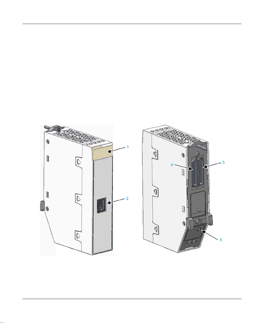
Physical Description
This figure shows the external features of the BMENUA0100 module:
for a description of
18
1 LED array
2 Control port with Ethernet link and activity LEDs
3 Ethernet backplane port
4 X Bus backplane port
5 Cybersecurity operating mode rotary selector switch
Refer to the topic LED Diagnostics
(see page 124)
for information on reading module LEDs.
PHA83350 11/2020
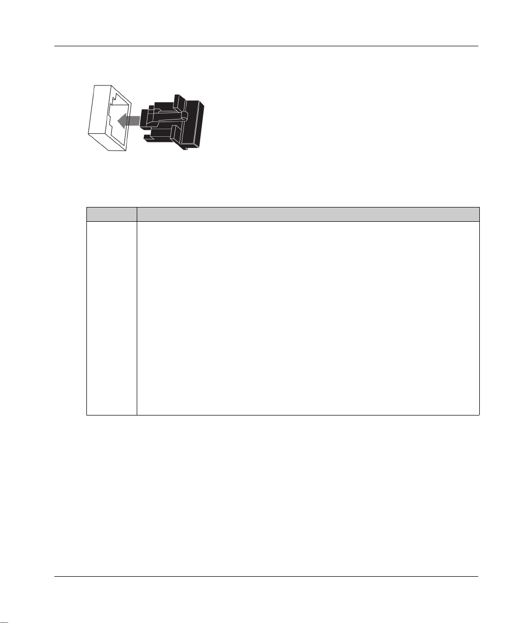
If the Ethernet control port is not enabled, use the stopper that ships with each module to help
prevent debris from entering the control port:
External Ports
The BMENUA0100 module includes the following external ports:
Port Description
Control port The control port is the single port located on the front of the BMENUA0100 module. Its features
BMENUA0100 Module Characteristics
include:
When the control port is enabled, it is the exclusive interface for OPC UA communications.
Operating speed up to 1 Gb/s. When operating at the speed of:
1 Gb/s, use only CAT6 copper shielded twisted four-pair cables.
10/100 Mb/s, use CAT5e or CAT6 copper shielded twisted four-pair cables.
Dual IP stack that supports both IPv4 (32 bit) and IPv6 (128 bit) IP addressing:
Both IPv4 and IPv6 are configured for the module.
IPv6 configuration can be static or dynamic (via SLAAC).
IPv4 default setting
(see page 113)
is auto-assigned based on the module MAC address,
if an IP address is not configured.
Secure access to the OPC UA server via both IPv4 and IPv6 protocols.
HTTPS secure protocol (over IPv4) for firmware upgrade
configuration
NTPv4 secure protocol support.
IPsec-provided security for non-secure services, including SNMPv1, Modbus TCP, and
(seepage88)
.
(see page 153)
and cybersecurity
Syslog.
PHA83350 11/2020 19

BMENUA0100 Module Characteristics
Port Description
Ethernet
backplane
port
X Bus
backplane
port
The BMENUA0100 Ethernet backplane port supports the IPv4 (32 bit) protocol. When the
control port is disabled, the backplane port can support OPC UA communications. the
backplane port includes the following features:
Operating speed up to 100 Mb/s.
Modbus TCP IPv4 Ethernet connectivity to the CPU:
The Ethernet backplane port is the exclusive port for Modbus diagnostics.
Exclusive port for non-cybersecurity configuration (IP, NTPv4, SNMPv1), by:
Control Expert v14.1 and later
FDR/DHCP server
If the control port is disabled, the Ethernet backplane port provides secure access to the
OPC UA server via the IPv4 protocol, and supports the following services:
HTTPS secure protocol for firmware upgrade
configuration
NTPv4, SNMPv1 and Syslog.
The BMENUA0100 module uses X Bus backplane communication to:
Receive 24 Vdc power.
Discover the rack and slot address of the BMENUA0100 module.
NOTE: No other communication is performed via the X Bus backplane port of the
BMENUA0100 module.
Rotary Switch
A three-position rotary switch is located on the back of the module. Use only the small, plastic
screwdriver that ships with the module to change the switch position and configure a cybersecurity
operating mode for the module.
(seepage88)
(see page 153)
.
and cybersecurity
20
NOTICE
RISK OF UNINTENDED OPERATION
Use only the small, plastic screwdriver that ships with the module to change the rotary switch
position. Using a metal screwdriver can damage the switch, rendering it inoperable.
Failure to follow these instructions can result in equipment damage.
PHA83350 11/2020
BMENUA0100 Module Characteristics
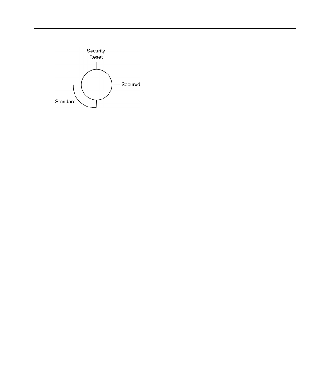
The positions on the rotary switch are:
The settings are:
Secured mode
Standard mode
Security Reset
NOTE:
The rotary switch is not accessible when the module is placed on the rack.
In a Hot Standby system, verify that the BMENUA0100 module rotary switch positions – in both
the primary and the standby local main racks – are the same. The system does not automatically
perform this check for you.
Refer to the description of cybersecurity operating modes
(seepage28)
for information on each
rotary switch position setting.
PHA83350 11/2020 21
BMENUA0100 Module Characteristics
Module LEDs
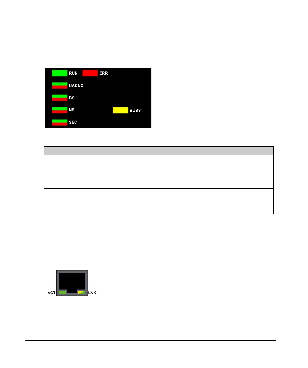
LED Display
A 7-LED display panel is located on the front of the BMENUA0100 module:
The LEDs display information about the module as follows:
LED Describes the state of the module:
RUN Operating condition.
ERR Detected errors.
UACNX OPC UA connections.
BS Backplane port.
NS Control port.
SEC Cybersecurity condition.
BUSY Data dictionary status
Refer to the LED Diagnostics topic
diagnose the state of the BMENUA0100 module.
Control Port LEDs
The control port, on the front of the module, presents two LEDs describing the state of the Ethernet
link over the port:
The ACT LED indicates the presence of Ethernet activity on the port.
The LNK LED indicates the existence of an Ethernet link and the link speed.
Refer to the LED Diagnostics topic
LEDs to diagnose the state of the BMENUA0100 module control port.
22
(see page 124)
(see page 127)
for information on how to use these LEDs to
for information on how to use the control port
PHA83350 11/2020

M580
Standards and Certificat ions
PHA83350 11/2020
Standards and Certificat ions
Chapter 2
Standards and Certifications
Overview
This chapter describes the standards and certifications that apply to the BMENUA0100 Ethernet
communications module with embedded OPC UA server.
What Is in This Chapter?
This chapter contains the following topics:
Standards and Certifications 24
BMENUA0100 Module Standards 25
BMENUA0100 Firmware Compatibility with EcoStruxure™ Control Expert 26
Topic Page
PHA83350 11/2020 23

Standards and Certifications
Standards and Certifications
Download
Click the link that corresponds to your preferred language to download standards and certifications
(PDF format) that apply to the modules in this product line:
Title Languages
Modicon M580, M340, and X80 I/O Platforms,
Standards and Certifications
English:
French:
German:
Italian:
Spanish:
Chinese:
EIO0000002726
EIO0000002727
EIO0000002728
EIO0000002730
EIO0000002729
EIO0000002731
24
PHA83350 11/2020

BMENUA0100 Module Standards
Agency Requirements
The BMENUA0100 OPC UA embedded Ethernet communication module conforms to the following
agency standards:
Marking Requirement
OPC UA V1.03: OPC Unified Architecture machine to machine communication protocol.
K3/C3 – K3/C2 nuclear certification; Cx certification validates overall quality level of the
PAC system, application, and with respect to our processes (to provide traceability,
development process and mastering, maturity in our overall quality management…); K3
deals with climatic or mechanical constraints, and consists of full environmental tests
under specific mechanical constraints.
Standards and Certifications
PHA83350 11/2020 25

Standards and Certifications
BMENUA0100 Firmware Compatibility with EcoStruxure™ Control Expert
Compatibility
Applications created with EcoStruxure™ Control Expert software are compatible with
BMENUA0100 module firmware as follows:
BMENUA0100 Firmware
Version
1.01 Fully compatible Only legacy features of firmware version 1.01 are
1.10 Fully compatible Fully compatible
1. If a BMENUA0100 module with firmware version 1.01 receives an application generated with
EcoStruxure™ Control Expert V15 where:
configure fast monitoring is Activated (in the IPConfig tab
implemented.
IPv4 is de-activated for the control port, the module control port will be configured with the IPv4 address
that appears grayed-out in the IPConfig tab for the module.
EcoStruxure™ Control Expert Software Version
14.0 15.0
supported by software
(seepage114)
1, 2, 3
), this setting will not be
NOTE: The grayed-out IPv4 address can be the most recently user-input IPv4 address, or the IPv4
address automatically input by the EcoStruxure™ Control Expert software (172.16.12.1) if no IPv4
address was previously entered.
NTP
(see page 118)
indicate NTP is operational when the NTP service actually is not operational.
2. If two BMENUA0100 modules with firmware version 1.01 are configured in a Hot Standby rack with
EcoStruxure™ Control Expert V15, the limitations described in the preceding items also apply to these
modules.
3. If SNMP is enabled in Control Expert, include the IPv4 address of the SNMP manager in the SNMP tab for
the BMENUA0100 module
has been configured with an IPv6 address, the module web pages mistakenly
(see page 119)
so that the SNMP manager can access the SNMP MIB.
26
PHA83350 11/2020

M580
Functional Description
PHA83350 11/2020
BMENUA0100 Functional Description
Chapter 3
BMENUA0100 Functional Description
Introduction
This chapter describes the supported functions of the BMENUA0100 Ethernet communications
module with embedded OPC UA server.
What Is in This Chapter?
This chapter contains the following sections:
Section Topic Page
3.1 Cybersecurity Operating Mode Settings 28
3.2 OPC UA Services 34
3.3 Discovering PAC Variables 49
3.4 Hot Standby and Redundancy 53
PHA83350 11/2020 27

Functional Description
Cybersecurity Operatin g Mode Settings
Section 3.1
Cybersecurity Operating Mode Settings
Cybersecurity Operating Modes
Introduction
The BMENUA0100 module can be configured to operate in either Secured or Standard mode. The
3-position rotary selector switch on the back of the module determines the operating mode.
The three rotary switch positions are:
Secured mode
Standard mode
Security Reset
NOTE:
The module’s default, out-of-the-box configuration, is the Secured mode.
You can view the current position of the rotary switch in the Home page
module web pages.
Because the rotary selector switch is not accessible while the module is on the rack, the switch
position can be changed only when the module is powered off and removed from the rack. After a
new switch position is selected, the module can be re-inserted into the rack and power applied.
NOTE: Use only the small, plastic screwdriver that ships with the module
the switch position and configure a cybersecurity operating mode.
(see page 93)
(seepage20)
of the
to change
28
PHA83350 11/2020
Changing Operating Mode
Each time you switch the cybersecurity operating mode from Secured mode to Standard mode, or
from Standard mode to Secured mode, perform a Security Reset operation
configuring the new mode.
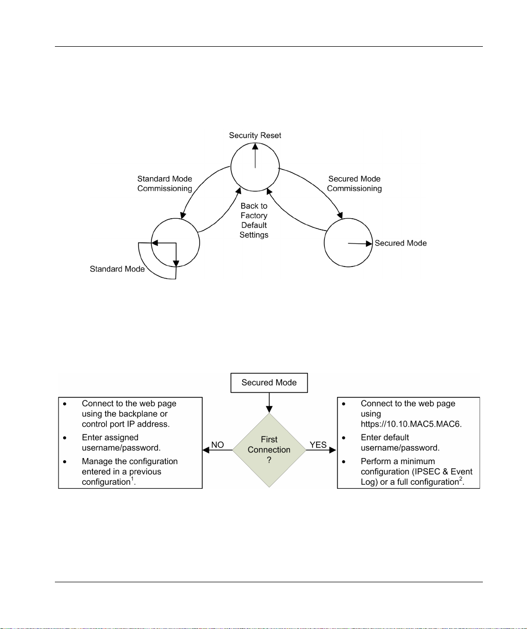
The position of the rotary switch determines the operating state of the module, as follows:
A new (out-of-the-box factory default) module, or a module for which a Security Reset has been
performed, can be commissioned for either Standard mode
(seepage81)
operations.
The process for configuring the module for Secured mode operations varies, depending on
whether you are connecting to the module configuration settings for the first time after performing
a security reset:
(see page 82)
Functional Description
(see page 83)
before
or Secured mode
1 For information about managing the configuration, refer to the configuration chapter.
2 For information on performing a configuration on first connection, refer to the topic Secured Mode
Commissioning
PHA83350 11/2020 29
(seepage81)
.
(see page 87)

Functional Description
Secured Mode
When operating in Secured mode, the module will not engage in process communications – over
either the control port or the backplane port – until valid cybersecurity settings have been
configured. After Secured mode has been configured, you can configure cybersecurity settings
using the module web pages
either the backplane or control ports. In Secured mode, the module supports the level of
cybersecurity that is specified in the cybersecurity configuration. Only after cybersecurity settings
have been configured, can IP address, NTP client, and SNMP agent settings
configured using the Control Expert configuration software.
Standard Mode
When operating in Standard mode, module communications can begin immediately. Cybersecurity
settings are not required and cannot be configured. Only the IP address and other settings
available in Control Expert can be configured.
Security Reset
The Security Reset command restores the out-of-the-box factory default configuration settings. It
deletes any existing cybersecurity configuration, white lists, certificates, and role based access
control settings. While the process of restoring factory default settings is ongoing, the RUN LED
continues blinking green. After completion of process, the RUN LED turns to solid green, and all
services are disabled. To complete the security reset, either cycle power (off, then on) to the
BMENUA0100 module, or physically remove the module from the rack (which turns off power) then
re-insert the module into the rack (which turns power back on).
This setting can be made using either the rotary switch or the web pages (when operating in
Secured mode):
If set via rotary switch: the module ceases to be functional until the module is removed from the
rack, the rotary switch is re-set to either the Secured or Standard position, and the module is
again placed on the rack. The necessary configuration(s) will need to be applied.
If set via the web pages: upon completion of the process cycle power (off / on) to – or hot swap
– the module in Standard or in Secured mode. Both the cybersecurity and IP address settings
need to be configured.
NOTE: After a Security Reset of the BMENUA0100 module, the following conditions apply to the
module:
No device certificates are preserved.
All services are disabled except for HTTPS, which is used to create the cybersecurity
configuration via the control port.
Factory default settings are applied, including:
Username / Password default settings
IP address default setting of 10.10.MAC5.MAC6
(seepage88)
, which can be accessed via the HTTPS protocol over
(see page 31)
(see page 113)
(see page 112)
.
.
be
30
PHA83350 11/2020

Functional Description
Default Username / Password Combination
The default username / password combination depends on the cybersecurity operating mode
setting:
Secured mode: admin / password
Standard mode: installer / Inst@ller1
Functions Supported by Secured and Standard Operating Modes
The following functions are supported by the BMENUA0100 module in Secured and Standard
modes:
Security Mode Standard mode Secured mode
Control port Disable Enable Disable Enable
Ethernet port Backplane Backplane Control port Backplane Backplane Control port
OPC UA Comm Yes No Yes Yes No Yes
Security
Settings (
None – None None, Sign,
3
)
Sign&Encrypt
(default value)
User
authentication
No
authentication
(anonymous)
–No
authentication
(anonymous)
Operator,
Engineer,
No authentication
(anonymous)
SNMP V1
NTP V4
1
Yes (
)Yes (
Client only (
1
1
)Yes (
) Client (1),
Server
1
)Yes (
Yes,
Client only (
Client only (*)
1
)
1
)Yes (
Event Log No No No Yes Yes Yes
IPSec No No No No No Yes for Modbus,
Web CS Config
No No No Yes Yes Yes
change
(HTTPS)
1. Configurable with Control Expert.
2. NTP V4 can be configured to be transported outside IPSec tunnel.
3. For both Standard and Secured cybersecurity operating modes, if Security Settings is set to
authentication (i.e. the User Identifier token types OPC UA setting
(see page 100)
4. To provide Control Expert with online access to the CPU or Device Network, configure the PC (on which Control
Expert is installed) with an IP address on the same subnet as the BMENUA0100 module control port, and use the
BMENUA0100 module control port IP address as the PC gateway IP address. In this case, no IP address of the
PC can be on the same subnet as the BMENUA0100 module backplane port.
– None, Sign,
Sign&Encrypt
(default value)
– Operator,
Engineer,
No authentication
(anonymous)
1
)Yes (
1
),
Client (
Server
1
)
Yes,
Client only (
SNMP V1,
NTP V4 (
2
Syslog (IPSec
enabled by
default)
None
, there is no user
is set to
Anonymous.
)
1
)
) and
PHA83350 11/2020 31

Functional Description
Security Mode Standard mode Secured mode
Control port Disable Enable Disable Enable
Ethernet port Backplane Backplane Control port Backplane Backplane Control port
User
– – – Admin Admin Admin
authentication
Network
Services Comm
server
Enable/Disable
If supported,
always
enabled (refer
above)
If
supported,
always
enabled
(refer
If supported,
always
enabled (refer
above)
All services are
configurable
(disabled by
default)
All services
are
configurable
(disabled by
default)
All services are
configurable
(disabled by
default)
above)
Web Diagnostic
Yes Yes Yes Yes Yes Yes
(Home and
Diagnostic
pages only)
User
authentication
Installer
(default
credentials)
Installer
(default
credentials)
Installer
(default
credentials)
Admin, Operator,
Engineer,
Installer
Admin,
Operator,
Engineer,
Admin, Operator,
Engineer,
Installer
Installer
Firmware
upgrade
Yes Yes Yes Yes Yes Yes, if HTTPS
enabled
(HTTPS)
User
authentication
Filtering: CPU to
CPU Data Flows
(Modbus)
Installer
(default
credentials)
Installer
(default
credentials)
Installer
(default
credentials)
– – Forward of
Modbus data
flow from CPU
(always
enabled)
Installer Installer Installer
– – Forward of
Modbus data flow
from CPU
(disabled by
default)
1. Configurable with Control Expert.
2. NTP V4 can be configured to be transported outside IPSec tunnel.
3. For both Standard and Secured cybersecurity operating modes, if Security Settings is set to
authentication (i.e. the User Identifier token types OPC UA setting
(see page 100)
is set to
None
, there is no user
Anonymous.
)
4. To provide Control Expert with online access to the CPU or Device Network, configure the PC (on which Control
Expert is installed) with an IP address on the same subnet as the BMENUA0100 module control port, and use the
BMENUA0100 module control port IP address as the PC gateway IP address. In this case, no IP address of the
PC can be on the same subnet as the BMENUA0100 module backplane port.
32
PHA83350 11/2020

Functional Description
Security Mode Standard mode Secured mode
Control port Disable Enable Disable Enable
Ethernet port Backplane Backplane Control port Backplane Backplane Control port
Filtering: Control
Expert Data
Flows to CPU
only (FTP, EIP,
Explicit,
Modbus, Ping)
Filtering: Control
Expert Data
Flows to Device
Network
(including CPU)
(FTP, EIP,
Explicit,
Modbus, Ping)
via IPv4 only
– – Forward of
4
– – Forward of
4
Control Expert
data flows
from Control
Network to
CPU only
(always
enabled)
4
Control Expert
data flows
from Control
Network to
Device
Network
(always
enabled)
– – Forward of
Control Expert
data flows from
Control Network
to CPU only
(disabled by
4
default)
– – Forward of
Control Expert
data flows from
Control Network
to Device
Network (disabled
by default)
1. Configurable with Control Expert.
2. NTP V4 can be configured to be transported outside IPSec tunnel.
3. For both Standard and Secured cybersecurity operating modes, if Security Settings is set to
authentication (i.e. the User Identifier token types OPC UA setting
(see page 100)
is set to
None
, there is no user
Anonymous.
)
4. To provide Control Expert with online access to the CPU or Device Network, configure the PC (on which Control
Expert is installed) with an IP address on the same subnet as the BMENUA0100 module control port, and use the
BMENUA0100 module control port IP address as the PC gateway IP address. In this case, no IP address of the
PC can be on the same subnet as the BMENUA0100 module backplane port.
PHA83350 11/2020 33

Functional Description
OPC UA Services
Section 3.2
OPC UA Services
Introduction
This section describes the services supported by the OPC UA server embedded in the
BMENUA0100 module.
What Is in This Section?
This section contains the following topics:
BMENUA0100 OPC UA Server Operating Characteristics 35
OPC UA Server 37
BMENUA0100 OPC UA Server Stack Services 39
BMENUA0100 OPC UA Server Stack Data Access Services 40
BMENUA0100 OPC UA Server Stack Discovery and Security Services 42
BMENUA0100 OPC UA Server Stack Publish and Subscribe Services 44
BMENUA0100 OPC UA Server Stack Transport Services 48
Topic Page
34
PHA83350 11/2020

BMENUA0100 OPC UA Server Operating Characteristics
Limitations
The maximum:
Number of nodes that can be published in the BMENUA0100 OPC UA Server data access
Address space is 100000 nodes.
Memory amount that can be allocated to the BMENUA0100 OPC UA Server is 4GB.
NOTE: If either limit is exceeded, the server Address Space state enters into a
state.
NOTE: The time needed to establish time subscription may significantly depend on the number of
items and the number of connected clients.
Other limitations, the context in which they occur, and their consequences if exceeded are set forth
below:
Limit Value OPCUA Service Service Parameter Effects
Cumulative
Session
Count
Minimum
Session
Timeout
Cumulative
Session
timeout
Maximum
Cumulative
Subscription
Count
Minimum
Publishing
Interval
Maximum
Publishing
Interval
Maximum
Subscription
Lifetime
1. If Fast Monitoring is disabled.
2. If Fast Monitoring is enabled.
3. If Fast Monitoring is disabled, and the server is configured with:
a sampling interval of at least 1 second, and
a publishing interval of at least 1 second.
10
30 s
3600 s
40
250 ms
20 ms
10 s
300 s
CreateSession
CreateSession
CreateSubscription
CreateSubscription
1
CreateSubscription
2
CreateSubscription
CreateSubscription
(Not Applicable)
Requested SessionTimeout revisedSession Timeout
Requested SessionTimeout revisedSession Timeout
(Not Applicable)
Requested Publishing
Interval
Requested Publishing
Interval
Min(Requested Publishing
Interval, 3600000) *
Requested LifetimeCount
Bad_TooManySessions
result code
Bad_TooManySubscriptions
service result code
revisedPublishingInterval
revisedPublishingInterval
revisedLifetimeCount
Functional Description
LimitsExceeded
s e r v i c e
PHA83350 11/2020 35

Functional Description
Limit Value OPCUA Service Service Parameter Effects
Maximum
Notifications
Per Publish
12500
CreateSubscription
maxNotificationsPerPublish Notifications maximum capacity
is thus (1000/
revisedPublishingInterval) *
1000 notifications per second.
Minimum
Sampling
Interval
Maximum
Message
125 ms
20 ms
100
1
CreateMonitoredtems
2
CreateMonitoredtems
MonitoringParameters.
SamplingInterval
MonitoringParameters.
QueueSize
revisedSampling Interval
revisedQueueSize
Queue Size
Maximum
Cumulative
Monitored
50000
2000
CreateMonitoredtems
2
(Not Applicable)
Bad_TooManyMonitoredItems
service result code
3
Items Count
Maximum
4– – –
Subscriptions
Per Session
Maximum
25000 – – –
Monitored
Items Count
Per
Subscription
1. If Fast Monitoring is disabled.
2. If Fast Monitoring is enabled.
3. If Fast Monitoring is disabled, and the server is configured with:
a sampling interval of at least 1 second, and
a publishing interval of at least 1 second.
36
PHA83350 11/2020

OPC UA Server
Introduction
The primary purpose of the BMENUA0100 Ethernet communication module is to provide an
OPC UA communication channel over Ethernet between M580 CPUs and OPC UA clients. The
data of the M580 CPU is mapped to variables in the BMENUA0100 module, and made available
to OPC UA clients via a high performance OPC UA server communication stack embedded in the
BMENUA0100 module. OPC UA clients connect to the embedded OPC UA server stack using IP
address of the BMENUA0100 module's control port or backplane port, thereby establishing a client
server connection. The BMENUA0100 module is able to handle a maximum of ten (10)
simultaneous OPC UA client connections for firmware version 1.1 (or three (3) simultaneous
OPC UA client connections for firmware version 1.0).
NOTE: The terms of each connection between an OPC UA client and the OPC UA server
embedded in the BMENUA0100 module are determined by the client, which sets the attributes of
the connection between the client and server.
The OPC UA server stack embedded in the BMENUA0100 module consists of functionalities
defined by the following terms:
Profile: a full-featured definition of functionality that comprises other profiles, facets,
conformance groups, and conformance units.
Facet: defines a partial functionality.
Conformance Group: a collection of conformance units.
Conformance Unit: a specific service, for example, read, write, and so forth.
Functional Description
BMENUA0100 Supported Profile
The BMENUA0100 module supports the Embedded 2017 UA Server Profile. As stated in the OPC
Foundation web site, this profile:
is a FullFeatured Profile that is intended for devices with more
than 50 MBs of memory and a more powerful processor. This Profile builds upon the Micro
Embedded Device Server Profile. The most important additions are: support for security via the
Security Policies and support for the Standard DataChange Subscription Server Facet. This Profile
also requires that Servers expose all OPC-UA types that are used by the Server including their
components and their super-types.
" For more information, refer tot he OPC Foundation website at:
http://opcfoundation.org/UA-Profile/Server/EmbeddedUA2017.
PHA83350 11/2020 37

Functional Description
BMENUA0100 Supported Facets
The BMENUA0100 module supports the following Facets:
Server Category → Facets → Core Characteristics:
Core 2017 Server Facet (
Server Category → Facets → Data Access:
ComplexType 2017 Server Facet (
Profile/Server/ComplexTypes2017
Data Access Server Facet (
Embedded DataChange Subscription Server Facet (
Profile/Server/EmbeddedDataChangeSubscription
Server Category → Facets → Generic Features:
Method Server Facet (
Security Category → Facets → Security Policy:
Basic128RSA15 (
Basic256 (
Basic256Sha256 (
Transport Category → Facets → Client-Server:
UA-TCP- UA-SC UA-Binary (
uabinary
http://opcfoundation.org/UA/SecurityPolicy#Basic256
)
The following topics discuss the services, related to the above-referenced facets, that are
supported by the BMENUA0100 module.
http://opcfoundation.org/UA-Profile/Server/Core2017Facet
http://opcfoundation.org/UA-
)
http://opcfoundation.org/UA-Profile/Server/DataAccess
http://opcfoundation.org/UA-
)
http://opcfoundation.org/UA-Profile/Server/Methods
)
http://opcfoundation.org/UA/SecurityPolicy#Basic128Rsa15
)
http://opcfoundation.org/UA/SecurityPolicy#Basic256Sha256
http://opcfoundation.org/UA-Profile/Transport/uatcp-uasc-
)
)
)
)
38
PHA83350 11/2020

BMENUA0100 OPC UA Server Stack Services
Supported OPC UA Services
The BMENUA0100 module OPC UA server stack supports the following service sets and services:
Service Set Services
Attribute
Discovery
MonitoredItem
SecureChannel
Session
Subscription
View
Read
Write
FindServers
GetEndpoints
CreateMonitoredItems
ModifyMonitoredItems
DeleteMonitoredItems
SetMonitoringMode
OpenSecureChannel
CloseSecurechannel
CreateSession
ActivateSession
CloseSession
CreateSubscription
ModifySubscription
DeleteSubscription
SetPublishingMode
SetMonitoringMode
Publish
Republish
Browse
BrowseNext
TranslateBrowsePathToNodeIds
RegisterNodes
UnregisterNodes
Functional Description
NOTE: For a description of these service sets and services, refer to the document
Architecture Specification Part 4: Services (Release 1.04)
PHA83350 11/2020 39
.
OPC Unified

Functional Description
BMENUA0100 OPC UA Server Stack Data Access Services
Supported Data Access Services
Data access by the BMENUA0100 module embedded OPC UA server stack is enabled by its
support of the following facets and related services:
Data Access Server Facet
ComplexType 2017 Server Facet
Core 2017 Server Facet
NOTE: In the following facet descriptions, italicized text indicates a direct quote of the OPC
Foundation source material. Click on the links below and use the
Architecture Profile Reporting Visualization Tool
Core 2017 Server Facet
The Core 2017 Server Facet
tation. The core functionality includes the ability to discover endpoints, establish secure
communication channels, create Sessions, browse the AddressSpace and read and/or write to
Attributes of Nodes. The key requirements are: support for a single Session, support for the Server
and Server Capabilities Object, all mandatory Attributes for Nodes in the AddressSpace, and
authentication with UserName and Password. For broad applicability, it is recommended that
Servers support multiple transport and security Profiles
http://opcfoundation.org/UA-Profile/Server/Core2017Facet
The BMENUA0100 module embedded OPC UA server stack supports the following conformance
units in the Core 2017 Server Facet:
View Service Set, includes the following groups and services:
View Basic: includes the Browse and the BrowseNext services.
View TranslateBrowsePath: includes the TranslateBrowsePathsToNodeIds service.
View Register Nodes: includes the RegisterNodes and UnregisterNodes services as a way
to optimize access to repeatedly used Nodes in the Server's OPC UA AddressSpace.
Attribute Service Set, includes the following groups and services:
Attribute read: includes the Read service, which supports reading one or more attributes of
one or more Nodes, including support of the IndexRange parameter to read a single element
or a range of elements when the Attribute value is an array.
Attribute Write values: includes the Write Value service, which supports writing one or more
values to one or more Attributes of one or more Nodes.
Attribute Write Index: includes the Write Index service, which supports the IndexRange for
writing to a single element or a range of elements when the Attribute value is an array and
partial updates is allowed for this array.
defines the core functionality required for any UA Server implemen
to access a description of each facet.
. For a full description of this facet, refer to
.
OPC Foundation Unified
-
40
PHA83350 11/2020

Data Access Server Facet
The Data Access Server Facet
industrial automation data. This model defines standard structures for analog and discrete data
items and their quality of service. This Facet extends the Core Server Facet which includes support
of the basic AddressSpace behaviour
http://opcfoundation.org/UA-Profile/Server/DataAccess
ComplexType 2017 Server Facet
The ComplexType 2017 Server Facet
structured data, i.e. data that are composed of multiple elements such as a structure and where
the individual elements are exposed as component variables. Support of this Facet requires the
implementation of structured DataTypes and Variables that make use of these DataTypes. The
Read, Write and Subscriptions service set shall support the encoding and decoding of these
structured DataTypes. As an option the Server can also support alternate encodings, such as an
XML encoding when the binary protocol is currently used and vice-versa
this facet, refer to
http://opcfoundation.org/UA-Profile/Server/ComplexTypes2017
Functional Description
specifies the support for an Information Model used to provide
. For a full description of this facet, refer to
.
extends the Core Server Facet to include Variables with
. For a full description of
.
PHA83350 11/2020 41

Functional Description
BMENUA0100 OPC UA Server Stack Discovery and Security Services
Introduction
The BMENUA0100 module embedded OPC UA server stack supports both discovery and security
services.
To connect to the OPC UA server in the BMENUA0100 module, an OPC UA client requires
information describing the server, including its network address, protocol, and security settings.
OPC UA defines a set of discovery features a client can use to obtain this information.
The information needed to establish a connection between an OPC UA client and an OPC UA
server is stored in an endpoint. An OPC UA server can possess several endpoints, each
containing:
Endpoint URL (network address and protocol), for example:
For IPv4: opc.tcp://172.21.2.30:4840, where:
- opc.tcp = protocols
- 172.21.2.30 = IPv4 address
- 4840 = opcua-tcp port number configured in Control Expert
For IPv6: opc.tcp://[2a01:cb05:431:f00:200:aff:fe02:a0a]:50000, where:
- opc.tcp = protocols
- [2a01:cb05:431:f00:200:aff:fe02:a0a] = IPv6 address
- 50000 = opcua-tcp port number configured in Control Expert
Security Policy (including a set of security algorithms and key length)
Message Security Mode (security level for exchanged messages)
User Token Type (server supported types of user authentication)
One or more OPC UA servers can exist. In the case of multiple servers, a discovery server can be
used to provide information regarding each server. Individual servers can register with the
discovery server. Clients can request a list of some or all of the available servers from the discovery
server and use the GetEndpoints service to acquire connection information from an individual
server.
42
PHA83350 11/2020

The BMENUA0100 module supports several discovery and security services, including:
Discovery Service Set
SecureChannel Service Set
Session Service Set
The decision to enable or disable services depends on the cybersecurity policy you decide to
implement for the server.
Discovery Service Set
The BMENUA0100 OPC UA server stack supports the Discovery Service Set, which is
incorporated in the Core 2017 Server Facet
module, the supported services include:
FindServers: As implemented in the BMENUA0100 module OPC UA server stack, this service
finds all servers only on the local OPC UA server.
GetEndpoints: Returns the Endpoints supported by a server and all of the configuration
information required to establish a SecureChannel and a Session. Can provide a filtered
Endpoints return list, based on profiles.
SecureChannel Service Set
The BMENUA0100 OPC UA server stack supports the SecureChannel Service Set, which includes
the following services:
OpenSecureChannel: Opens or renews a SecureChannel that provides confidentiality and
integrity for the exchange of messages during a session. This Service requires the OPC UA
server stack to apply the various security algorithms to the messages as they are sent and
received.
CloseSecureChannel: Terminates a SecureChannel.
(seepage40)
Functional Description
. As implemented in the BMENUA0100
Session Service Set
The BMENUA0100 OPC UA server stack supports the Session Service Set, which is incorporated
in the Core 2017 Server Facet
(see page 40)
. As implemented in the BMENUA0100 module, the
supported services include:
CreateSession: After creating a SecureChannel with the OpenSecureChannel service, a client
uses this service to create a session. The server returns two values which uniquely identify the
session:
A sessionId, which is used to identify the session in the audit logs and in the server's
AddressSpace.
An authenticationToken, which is used to associate an incoming request with a session.
ActivateSession: Used by the client to specify the identity of the user associated with the
session. It cannot be used to change the session user.
CloseSession: Terminates a session.
NOTE: For the CreateSession and ActivateSession services, if the SecurityMode = None then:
1. The Application Certificate and Nonce are optional.
2. The signatures are null/empty.
PHA83350 11/2020 43

Functional Description
BMENUA0100 OPC UA Server Stack Publish and Subscribe Services
Subscriptions
Instead of permanently reading information by polling, the OPC UA protocol includes the Subscription
function. This function enables the OPC UA high performance stack embedded in the BMENUA0100
module to provide publish/subscribe services, which are used when the module connects to remote
devices.
An OPC UA client can subscribe to one or more selected nodes and let the server monitor these
items. Upon the occurrence of a change event, for example a change in value, the server notifies the
client of the change. This mechanism significantly reduces the quantity of data that is transferred. This
reduces bandwidth consumption and is the recommended mechanism for reading information from
an OPC UA server.
An OPC UA client can subscribe to the multiple types of information that an OPC UA server provides.
The subscription groups together these varying types of data, called Monitored Items, to form a single
collection of data called a Notification.
A subscription must:
Consist of at least one Monitored Item.
Be created within the context of a Session, which is created within the context of a
Secure Channel.
NOTE: The subscription can be transferred to another session.
The service sets involved in a client subscription are described below:
Subscriptions and Overruns
In some cases, where there exists a large number of subcription requests, the OPC UA server
attempts to obtain data from the CPU in an amount greater than the CPU or the BMENUA0100
module can handle in the specified publishing interval. In this case, the execution time for
subscription requests will be automatically extended – and the next subscription execution
postponed – until all requests can be completed.
When setting a publishing interval, consider the number of clients and client requests the server
needs to handle. When determining the number of client requests, confirm that all clients are
operating online. In this regard, note that some clients can take 2 minutes or more to come online
after startup.
NOTE: A publishing interval equal to twice the sampling interval is recommended.
44
PHA83350 11/2020

Change Events
A client can subscribe to a data change event, which is triggered by a change to the value attribute
of a variable, as a Monitored Item.
The configurable subscription settings, their sequence and roles, are described below:
The following three settings determine how Monitored Items are added to a subscription:
Sampling Interval: the sampling time interval set for each Monitored Item in the subscription.
This is the frequency by which the server checks the data source for changes. For a single
Variable item, the Sampling Interval can be smaller (i.e. faster) than the period between
notifications to the client. In this case, the OPC UA Server may queue the samples and publish
the complete queue. In extreme cases, the server will revise (i.e. slow) the Sampling Interval so
that the data source will not experience excessive queuing load that may be caused by the
sampling itself.
NOTE: If OPC UA queuing of data samples is supported, the queue size (i.e., the maximum
number of values which can be queued) can be configured for each monitored item. When the
data is delivered (published) to the client, the queue is emptied. In case of a queue overflow,
the oldest data is discarded and replaced by new data.
Filter: a collection of several criteria used to identify which data changes or events are reported,
and which should are blocked.
Monitoring Mode: used to enable or disable data sampling and reporting.
The following two settings apply to the Subscription itself:
Publishing Interval: The period after which notifications collected in the queues are delivered to
the client in a Notification Message (Publish Response). The OPC UA Client must confirm that
the OPC UA server has received enough Publish Tokens (Publish Requests), so that whenever
the Publish Interval elapsed and a notification is ready to send, the server uses such a token
and sends the data within a Publish Response. In case that there is nothing to report (e.g. no
values have changed) the server will send a KeepAlive notification to the Client, which is an
empty Publish, to indicate that the server is still alive.
Publish Enabled: Enables and disables the sending of the Notification Message.
Functional Description
PHA83350 11/2020 45

Functional Description
Embedded DataChange Subscription Server Facet
The Embedded DataChange Subscription Server Facet
data change notifications within subscriptions. It includes limits which minimize memory and
processing overhead required to implement the Facet. This Facet includes functionality to create,
modify and delete Subscriptions and to add, modify and remove Monitored Items. As a minimum
for each Session, Servers shall support one Subscription with up to two items. In addition, support
for two parallel Publish requests is required. This Facet is geared for a platform such as the one
provided by the Micro Embedded Device Server Profile in which memory is limited and needs to
be managed.
For a full description of this facet, refer to
Profile/Server/EmbeddedDataChangeSubscription
This facet supports the following services:
Monitored Item Service Set
Subscription Service Set
Monitored Item Service Set
The Monitored Item Service Set supports the following services:
CreateMonitoredItems: An asynchronous call used to create and add one or more
MonitoredItems to a subscription.
ModifyMonitoredItems: an asynchronous call to modify monitored items. This service is used to
modify MonitoredItems of a subscription. Changes to the MonitoredItem settings shall be
applied immediately by the server. They take effect as soon as practical.
DeleteMonitoredItems: an asynchronous call to delete monitored items. This service is used to
remove one or more MonitoredItems of a subscription. When a MonitoredItem is deleted, its
triggered item links are also deleted.
SetMonitoringMode: an asynchronous call to set the monitoring mode for a list of
MonitoredItems. This service is used to set the monitoring mode for one or more
MonitoredItems of a subscription. Setting the mode to DISABLED causes all queued
notifications to be deleted.
specifies the minimum level of support for
http://opcfoundation.org/UA-
.
46
PHA83350 11/2020

Subscription Service Set
The Subscription Service Set supports the following services:
CreateSubscription: an asynchronous call to create a subscription.
ModifySubscription: an asynchronous call to modify a subscription. The server immediately
applies changes to the subscription, and changes take effect as soon as practical.
DeleteSubscription: an asynchronous call to delete one or more subscriptions belonging to the
client session. Successful completion of this service deletes all Monitored Items associated with
the subscription.
Publish: This Service is used for two purposes: to acknowledge the receipt of Notification-
Messages for one or more subscriptions, and to request the server to return a
NotificationMessage or a keep-alive message.
Republish: an asynchronous republish call to get lost notifications. This service requests the
subscription to republish a NotificationMessage from its retransmission queue. If the server
does not have the requested message in its retransmission queue, it returns an error response.
SetPublishingMode: an asynchronous call to enable sending of Notifications on one or more
subscriptions.
Functional Description
PHA83350 11/2020 47

Functional Description
BMENUA0100 OPC UA Server Stack Transport Services
Support for the UA-TCP UA-SC UA-Binary Facet
The BMENUA0100 module supports the UA-TCP UA-SC UA-Binary transport facet. (For
additional information, refer to the online description at
Profile/Transport/uatcp-uasc-uabinary
.)
This transport facet defines a combination of network protocols, security protocols, and message
encoding that is optimized for low resource consumption and high performance. It combines the
simple TCP-based network protocol UA-TCP 1.0 with the binary security protocol UA-SecureConversation 1.0 and the binary message encoding UA-Binary 1.0.
Data that passes between an OPC UA client and the BMENUA0100 module embedded OPC UA
server uses the TCP protocol, and is binary coded in accordance with the OPC UA Binary File
Format.
NOTE: The OPC UA Binary File Format replaces the XML UA-Nodeset Schema from the OPC
Foundation. It improves performance and memory consumption. It does not require an XML
parser.
http://opcfoundation.org/UA-
48
PHA83350 11/2020

Functional Description
Discovering PAC Varia bles
Section 3.3
Discovering PAC Variables
Mapping Control Expert PAC Variables to OPC UA Data Logic Variables
Introduction
The OPC UA embedded server in the BMENUA0100 module uses Unified Messaging Application
Services (UMAS) data dictionary requests to browse and discover M580 PAC application
variables. You will need to activate the data dictionary in the Control Expert project settings.
NOTE:
The BMENUA0100 module can support a maximum data dictionary size of 100000 variables.
The time required to load the data dictionary into the OPC UA server depends on the number
of data dictionary items and the MAST period setting
All collected variables are translated from the Control Expert data logic model view to the OPC UA
data logic model view using the appropriate OPC UA stack services. An OPC UA client connected
to the BMENUA0100 module–over its control port, or over its backplane port via the CPU or a
BMENOC0301/11 communication module–can retrieve this collection of data using the services of
the Data Access Server Facet
(seepage37)
.
(seepage41)
supported by the Embedded 2017 UA Server Profile
(seepage151)
.
Preloading the Data Dictionary to Avoid Communication Interruptions
An online application change made with Control Expert temporarily breaks OPC UA server/client
communication while the server acquires an updated data dictionary. This interruption is caused
by inconsistent CPU data mapping while the data dictionary is updated. During the period of
communication loss, the status of the monitored nodes goes to BAD. To avoid this disruption of
operations, a synchronization mechanism can be set up between the BMENUA0100 module and
the Control Expert configuration software, based on a preload of the updated data dictionary.
This feature is enabled in Control Expert in the Tools → Project Settings... window, in the General
→ PLC embedded data area, using the Preload on build changes and
Effective Build changes time-out settings
Refer to the Control Expert online help for these topics for information on how to configure this
feature.
PHA83350 11/2020 49
(see EcoStruxure™ Control Expert, Operating Modes)
.

Functional Description
Activating the Data Dictionary
To activate the data dictionary in Control Expert:
Step Action
1 In Control Expert, with the project open, select Tools → Project Settings.
2 In the Project Settings window, navigate to General → PLC embedded data, then select Data
dictionary.
NOTE: If the EcoStruxure™ Control Expert project includes a BMENUA0100 module and this
setting is not selected, a detected error is generated during the application build.
Variable Data Type Conversion
The BMENUA0100 module can discover and convert to OPC UA data types the following basic
variable types supported by the Control Expert data logic model:
Control Expert Elementary Data Type OPC UA Data Type
EBOOL Boolean
UDINT UInt32
WORD UInt16
DWORD UInt32
DATE* UInt32
STRING Byte array
* Refer to following table describing date-related data type conversion.
BOOL Boolean
INT Int16
DINT Int32
UINT UInt16
REAL Float
BYTE Byte
TIME* UInt32
TOD* UInt32
DT* Double
50
For Control Expert data of types DATE, TIME, TOD, DT, the corresponding OPC UA data types
are as follows:
Control Expert
Elementary Data Type
DATE D#2017-05-17 UInt32 0x20170517
TIME T#07h44m01s100ms UInt32 27841100
TOD TOD#07:44:01 UInt32 0x07440100
DT DT#2017-05-17-07:44:01 Double 4.29E-154
Example value displayed in
Control Expert
OPC UA
Data Type
Corresponding value
in OPC UA type
PHA83350 11/2020

Discoverable Variables
For all variables, the OPC UA client does not directly access a discovered PAC data logic variable.
Instead, the client accesses the discovered PAC variable through an OPC UA data logic variable,
which exists in the BMENUA0100 module and is mapped to the underlying PAC variable. Because
of the pass-through nature of data variable access, the acquisition request process is not
optimized, and data dictionary acquisition performance is not representative of PAC performance.
NOTE: References, of the REF_TO type, to application variables in the OPC UA server are not
accessible by the OPC UA client.
Examples of Control Expert PAC variables discoverable by the OPC UA server in the
BMENUA0100 module include:
Structured variables with sub-fields: DDT and array variables.
Program Unit variables are discoverable as follows:
Input/Output variables are accessible by the OPC UA client only for the BOOL type.
Input variables and Output variables are accessible by the OPC UA client, except for the
types REF_TO, ARRAY, String, and Structure.
In addition, the following variables are discoverable by the OPC UA server by mapping them to
application varables, then discovering the mapped application variables:
Topological I/O variables:
Inputs: %I, %IW, %ID, %IF.
Outputs: %Q, %QW, %QD, %QF.
Located variables: %M, %MW, %MD, %MF.
System variables: %S, %SW, %SD.
NOTE: Variable discovery includes a variable (or symbol) for an extracted bit (for example,
MyBoolVar located on %MW100.1).
Functional Description
Presentation of Discovered Variables in the OPC UA Client
The OPC UA server in the BMENUA0100 module can organize and graphically display discovered
PAC variables. An OPC UA client tool can connect to the BMENUA0100 module and view a node
tree presentation of OPC UA server variables.
PHA83350 11/2020 51

Functional Description
In the following example, an OPC UA client (in this example, the Unified Automation UaExpert
client tool) connected to the BMENUA0100 module can view PAC variables in its Address Space
windows. The M580 PAC IP address is represented by the node ePAC:192.168.10.1. Its child
nodes represent Control Expert application variables:
In the example above, the first sub-node, BMEP58_ECPU_EXT, represents the device DDT for the
M580 CPU, which is automatically instantiated when the CPU was added to the Control Expert
application. The subsequent nodes represent other objects added to the application.
Using the OPC UA client tool, the node TEST_S6 was dragged and dropped into the tool's
Data Access View window, where the details of the variable are displayed:
In this case, the variable OPC UA data type is
BOOL) and its value is
false
.
Boolean
(indicating the underlying PAC data type is
NOTE: The Server Timestamp attribute of the OPC UA nodes is received from the BMENUA0100
OPC UA server in UTC (Universal Time Coordinated). It is displayed to the user in local time. The
data are not timestamped at their respective sources, but are timestamped by the OPC UA server.
To avoid compatibility conflicts with some OPC UA clients, both source timestamp and server
timestamp values are setup with the same server timestamp value.
Reading and Writing Discovered Variables in the OPC UA Client
An OPC UA tag in an OPC UA client (for example a SCADA) that refers to an array variable allows
the client to read or write all elements of the array. For example the tag ‘MyArray’ declared as
ARRAY[0...31] OF INT.
However, for the client to be able to read or write only a single element of an array, it is necessary
to declare a specific tag that references the targeted single array element. For example ‘MyInt’
declared as INT referring to MyArray[2].
52
PHA83350 11/2020

Hot Standby and Redun dancy
Section 3.4
Hot Standby and Redundancy
OPC UA Server Redundancy
Two Types of Redundancy
The BMENUA0100 module supports the following types of redundancy:
Hot Standby architecture, which describes redundant CPUs.
OPC UA server redundancy, which describes the use of redundant BMENUA0100 modules.
The redundancy of OPC UA servers, which is managed by the BMENUA0100 modules, follows the
OPC UA standard
These two types of redundancy can be combined. The following designs are supported:
A standalone PAC, containing two BMENUA0100 modules.
Two Hot Standby PACs, each containing one or two BMENUA0100 modules.
OPC UA Redundancy
In an OPC UA non-transparent server redundant architecture in warm failover mode, it is the
responsibility of the OPC UA client to establish sessions and to manage communications with
redundant servers. The sessions to be established include: an active session with the primary
server and an inactive session with the secondary (or standby) server. The client needs to
configure these two sessions to include the same monitored items.
It is also the responsibility of the OPC UA client to check the status of the two servers via the
SERVICE_LEVEL variable, and to switch the communication to the healthier server, depending on
the value of this variable.
The OPC UA standard holds that the activation of communications is accomplished by adjusting
Monitoring Mode
the
is controlled by the OPC UA client, and the procedure for adjusting it depends on the implementation of the client. For more information about adjusting
documentation.
This principle is a general principle, and applies to any architecture, including an the Hot Standby
architecture.
non-transparent server redundancy in warm failover mode.
of the different sessions to the right value. The
Monitoring Mode
Monitoring Mode
Functional Description
of the servers
, refer to the client
PHA83350 11/2020 53

Functional Description
The following diagram depicts an OPC UA client connected to a pair of redundant OPC UA servers
(each embedded in a BMENUA0100 module). The client has designated as the active server the
one with the higher SERVICE_LEVEL value:
Hot Standby
In a Hot Standby configuration, a maximum of two (2) BMENUA0100 modules can be installed in
each Hot Standby main local rack. Each BMENUA0100 module is configured with a unique, static
IP address. The BMENUA0100 modules will retain their respective IP addresses, and will not
exchange IP addresses on a Hot Standby switchover or swap.
NOTE: In a Hot Standby system, verify that the BMENUA0100 modules in the primary and the
standby PACs:
Are configured with identical cybersecurity settings
Have their rotary selector switches
Are installed in the same slot number
The system will not automatically perform these checks for you.
The BMENUA0100 module DDT includes the SERVICE_LEVEL
provides information to the CPU regarding the health of the OPC UA server in the BMENUA0100
module. The OPC UA client is informed of the status of the OPC UA server via the
SERVICE_LEVEL variable, which is available as an OPC UA variable.
54
same position.
(see page 20)
(seepage62)
(see page 88)
, and
(located on the back of the module) set to the
in their respective local main racks.
(see page 137)
variable, which
PHA83350 11/2020

Functional Description
NOTE: Always include the READ_DDT elementary function, for the purpose of updating the DDT
of each BMENUA0100 module. In a Hot Standby configuration, add the READ_DDT to a code
section that executes when the CPU is in standby mode. This design returns BMENUA0100
diagnostic information that can be exchanged between the primary and standby CPUs. The
application can use this information to perform a consistency check of the supported services and
the cybersecurity configurations for the BMENUA0100 modules in the primary and standby CPUs.
If the Hot Standby CPU T_M_ECPU_HSBY DDT
Planning Guide for, Frequently Used Architectures)
(see Modicon M580 Hot Standby, System
and its CMD_SWAP element are made
available as HMI variables in a SCADA system, the SCADA application can trigger a swap by
writing to the appropriate mapped OPC UA variable in the BMENUA0100.
In a Hot Standby system, the BMENUA0100 module that manages OPC UA communications with
the SCADA may be the one located in the standby local rack. For this reason, you need to select
the Exchange on STBY attribute for all scanned application variables to provide consistency of
variable values between the primary and standby PACs.
In addition, to maintain consistency, the applications in the two Hot Standby PACs need to be
synchronized.
In rare cases (primarily when the ECPU_HSBY_1.PLCX_ONLINE bit is set to false either manually
or programmatically), one of the PACs in a Hot Standby system may be in Wait mode. In this mode,
this PAC (the standby) is not synchronized with the primary PAC and variables read from this PAC
are inaccurate. The state of a responding PAC may be monitored via the following
T_M_ECPU_HSBY DDT fields:
T_M_ECPU_HSBY_1.LOCAL_HSBY_STS.WAIT
T_M_ECPU_HSBY_1.LOCAL_HSBY_STS.RUN_PRIMARY
T_M_ECPU_HSBY_1.LOCAL_HSBY_STS.RUN_STANDBY
T_M_ECPU_HSBY_1.LOCAL_HSBY_STS.STOP
Also, the Hot Standby system permits the two PACs to operate while running different applications.
To provide for the consistency of variables between the primary and standby PACs, the data layout
of the 2 PACs needs to be consistent, as shown by the T_M_ECPU_HSBY DDT field:
T_M_ECPU_HSBY_1.DATA_LAYOUT_MISMATCH = false
NOTE: When OPC UA redundancy is configured, it is recommended that you programmatically
check the module DDTs to confirm that the supported services and the cybersecurity
configurations for the BMENUA0100 modules are consistent.
NOTE: In the following parts of this topic, content is borrowed from the document:
OPC Unified Architecture Specification Part 4: Services, Release 1.04
as
OPC UA Part 4
in
italics
.
, followed by the appropriate section reference. The borrowed content appears
, which is abbreviated below
PHA83350 11/2020 55

Functional Description
OPC UA Support for Redundant Servers, Clients, and Networks
OPC UA enables Servers, Clients and networks to be redundant. OPC UA provides the data
structures and Services by which Redundancy may be achieved in a standardized manner.
Server Redundancy allows Clients to have multiple sources from which to obtain the same data.
Server Redundancy can be achieved in multiple manners, some of which require Client interaction,
others that require no interaction from a Client. Redundant Servers could exist in systems without
redundant networks or Clients. Redundant Servers could also coexist in systems with network and
Client Redundancy...
Client Redundancy allows identically configured Clients to behave as if they were single Clients,
but not all Clients are obtaining data at a given time. Ideally there should be no loss of information
when a Client Failover occurs. Redundant Clients could exist in systems without redundant
networks or Servers. Redundant Clients could also coexist in systems with network and Server
Redundancy...
Network Redundancy allows a Client and Server to have multiple communication paths to obtain
the same data. Redundant networks could exist in systems without redundant Servers or Clients.
Redundant networks could also coexist in systems with Client and Server Redundancy...
OPC UA Part 4, section 6.6.1.
Server Redundancy
There are two general modes of Server Redundancy, transparent and non-transparent.
In transparent Redundancy the Failover of Server responsibilities from one Server to another is
transparent to the Client. The Client is unaware that a Failover has occurred and the Client has no
control over the Failover behaviour. Furthermore, the Client does not need to perform any actions
to continue to send or receive data.
In non-transparent Redundancy the Failover from one Server to another and actions to continue
to send or receive data are performed by the Client. The Client must be aware of the Redundant
Server Set and must perform the required actions to benefit from the Server Redundancy.
The ServerRedundancy Object ... indicates the mode supported by the Server. The ServerRedun
dancyType ObjectType and its subtypes TransparentRedundancyType and
NonTransparentRedundancyType ... specify information for the supported Redundancy mode.
OPC UA Part 4, section 6.6.2
As noted above, the OPC UA server in the BMENUA0100 supports non-transparent server
redundancy in warm failover mode.
-
56
PHA83350 11/2020

OPC UA Server Warm Failover Mode
Warm failover mode
. Therefore, only a single server will be able to consume data of the Control Expert
points
application.
The ServiceLevel Variable ... indicates the ability of the Server to provide its data to
is where the backup Server(s) can be active, but cannot connect to actual data
the Client. OPC UA Part 4, section 6.6.2.4.4
Functional Description
When there is failover, action by the OPC UA client is needed; the OPC UA server embedded in
BMENUA0100 becomes inactive:
PHA83350 11/2020 57

Functional Description
Client Failover Behavior
Each Server maintains a list of ServerUris for all redundant Servers in the Redundant Server Set.
NOTE: A Redundant Server Set is the collection of OPC UA servers in the Control Expert
application that are configured to provide redundancy.
The list is provided together with the Failover mode in the ServerRedundancy Object. To enable
Clients to connect to all Servers in the list, each Server in the list shall provide the ApplicationDe
scription for all Servers in the Redundant Server Set through the FindServers Service. This
information is needed by the Client to translate the ServerUri into information needed to connect
to the other Servers in the Redundant Server Set. Therefore, a Client needs to connect to only one
of the redundant Servers to find the other Servers based on the provided information. A Client
should persist information about other Servers in the Redundant Server Set.
OPC UA Part 4, section 6.6.2.4.5.1
Client options in warm failover mode include:
On initial connection, in addition to actions on Active Server:
Connect to more than one OPC UA Server.
Create Subscriptions and add monitored items.
At failover:
Activate sampling on the subscriptions.
Activate publishing.
-
58
PHA83350 11/2020

Functional Description
Clients communicating with a non-transparent Redundant Server Set of Servers require some
additional logic to be able to handle Server failures and to Failover to another Server in the
Redundant Server Set.
The following figure
provides an overview of the steps a Client typically
performs when it is first connecting to a Redundant Server Set.
The initial Server may be obtained via standard discovery or from a persisted list of Servers in the
Redundant Server Set. But in any case the Client needs to check which Server in the Server set it
should connect to. Individual actions will depend on the Server Failover mode the Server provides
and the Failover mode the Client will make use.
Clients once connected to a redundant Server have to be aware of the modes of Failover
supported by a Server since this support affects the available options related to Client behaviour.
A Client may always treat a Server using a lesser Failover mode, i.e. for a Server that provide Hot
Redundancy, a Client might connect and choose to treat it as if the Server was running in Warm
Redundancy or Cold Redundancy. This choice is up to the client. In the case of Failover mode
HotAndMirrored, the Client shall not use Failover mode Hot or Warm as it would generate
unnecessary load on the Servers. OPC UA Part 4, section 6.6.2.4.5.1
PHA83350 11/2020 59

Functional Description
OPC UA Client Warm Failover Mode
In Warm Failover mode,
the Client should connect to one or more Servers in the Redundant Server
Set primarily to monitor the ServiceLevel. A Client can connect and create Subscriptions and
MonitoredItems on more than one Server, but sampling and publishing can only be active on one
Server. However, the active Server will return actual data, whereas the other Servers in the
Redundant Server Set will return an appropriate error for the MonitoredItems in the Publish
response such as Bad_NoCommunication. The one Active Server can be found by reading the
ServiceLevel Variable from all Servers.
The Server with the highest ServiceLevel is the Active Server. For Failover the Client activates
sampling and publishing on the Server with the highest ServiceLevel. Figure 30 illustrates the steps
a Client would perform when communicating with a Server using Warm Failover mode.
60
OPC UA Part 4, section 6.6.2.4.5.3
PHA83350 11/2020

M580
Architectures
PHA83350 11/2020
Supported Architectures
Chapter 4
Supported Architectures
Introduction
This chapter describes the topological architectures supported by the BMENUA0100 Ethernet
communication module with embedded OPC UA server.
What Is in This Chapter?
This chapter contains the following topics:
Supported BMENUA0100 Module Configurations 62
Isolated Control Network with M580 Hot Standby PACs 64
Non-Isolated Flat Network with M580 Hot Standby 66
Flat Network with Multiple M580 Standalone CPUs and Single SCADA 68
Flat Network with Multiple M580 Standalone CPUs and Redundant SCADA 70
Flat Network with M580 Hot Standby CPUs and Redundant SCADA 72
Hierarchical Network featuring Multiple M580 Standalone CPUs Connected to Control Network
and Redundant SCADA
Hierarchical Network with Multiple M580 Hot Standby CPUs and Redundant SCADA
Connections
Topic Page
74
76
PHA83350 11/2020 61

Architectures
Supported BMENUA0100 Module Configurations
Placement of the BMENUA0100 Module
The BMENUA0100 module can be placed into an Ethernet slot on the local main rack (i.e. in the
same rack as the CPU) in the following configurations:
an M580 standalone configuration.
an M580 standalone Safety PAC configuration.
an M580 Hot Standby configuration.
an M580 Hot Standby Safety PAC configuration.
NOTE:
The BMENUA0100 module can be used with all M580 CPUs.
In the event a network loop is created, the BMENUA0100 module goes into NOCONF (Not
configured) state. To help prevent loops and related events, when you use the BMENUA0100
control port, split the control port network and the CPU backplane network physically (via wiring
splitting) and not only logically (via the subnet and subnet mask settings).
Connecting via the HTTPS Protocol
If your application experiences connection problems, check with your local IT support to confirm
that your network configuration and security policies are consistent with HTTPS (port 443) access
to the BMENUA0100 module IP address.
The BMENUA0100 module accepts the HTTPS connections with transport layer security (TLS)
protocol v1.2 or later. For example, Windows 7 could require an update to enable TLS 1.2 to
upgrade the firmware of the BMENUA0100 or access to its web site.
Installation of the BMENUA0100 Module in a Flat Network
For multiple M580 racks connected on a single subnet (i.e., a flat network architecture) that include
BMENUA0100 modules with the control port disabled, install each BMENUA0100 module in a
different slot number in its respective rack (except for Hot Standby configurations, where the
BMENUA0100 modules are installed in the same slot number). Alternatively, it is strongly
recommended that you use a router to isolate the racks and thereby avoid potential address
conflicts among BMENUA0100 modules.
Access to the BMENUA0100 embedded OPC UA Server
In the topological architectures described in this chapter, the BMENUA0100 communication
module Ethernet backplane port and its control port do not simultaneously provide access to the
OPC UA server embedded in the module. OPC UA clients can access the OPC UA server
embedded in the BMENUA0100 module either via the control port when it is enabled, or via the
Ethernet backplane port when the control port is disabled.
62
PHA83350 11/2020

Maximum Number of BMENUA0100 modules per Configuration
The maximum number of BMENUA0100 modules supported in an M580 configuration are:
M580 Configuration Type Maximum Number of BMENUA0100 Modules
Standalone
Safety PAC
Two (2) in the local main rack for both standalone
standard and safety configurations.
Hot Standby
Hot Standby Safety PAC
1. When two (2) BMENUA0100 modules are used in a main rack:
Performance of each module will be slower than if a single module had been used.
Enable the control port in the configuration for both modules.
2. In Hot Standby designs, place the BMENUA0100 module(s) in the same slot number(s) in the respective
local main racks.
Change Configuration on the Fly (CCOTF)
The BMENUA0100 module does not support CCOTF.
1
and Hot Standby
Architectures
1,2
PHA83350 11/2020 63

Architectures
Isolated Control Network with M580 Hot Standby PACs
Architecture
64
1 Primary Hot Standby PAC
2 Standby Hot Standby PAC
3 BMENUA0100 Ethernet communications module with embedded OPC UA server
4 OPC UA client (SCADA system)
5 Engineering workstation with dual Ethernet connections
6 X80 Ethernet RIO drop
7 Distributed equipment
8 Control network
9 Ethernet RIO main ring
10 Hot Standby communication link
11 Dual ring switch (DRS)
PHA83350 11/2020

Description
This architecture provides redundant connections to dual OPC UA clients (SCADA systems).
Cybersecurity can be either enabled or disabled in this architecture. The control network (8) is
logically isolated from both the Ethernet devices that reside in the Ethernet RIO main ring (9),
including the CPU, and the distributed Ethernet devices (7). This is accomplished at the Network
layer of the OSI model via IP addressing.
The BMENUA0100 control port (3), with its dual IPv6/IPv4 stacks, allows upstream connectivity to
the control network. When communicating via IPv6, it supports both stateless address autoconfiguration (SLAAC) and static IP addressing.
The BMENUA0100 provides Modbus peer-to-peer communication between the two Hot Standby
CPUs. The CPU device ports provide downstream connectivity to the Ethernet devices on the
Ethernet RIO main ring.
Each BMENUA0100 is a client of an NTP server that resides in the control network. The connection
is made through the BMENUA0100 control port. The BMENUA0100 modules also serve as NTP
servers for other devices in the Ethernet RIO main ring. In this Hot Standby design, the
BMENUA0100 module configured as “A” acts is the primary NTP server, and the BMENUA0100
module configured as “B” acts is the standby NTP server. In this way, the CPU time and the
BMENUA0100 module time are synchronized.
The BMENUA0100 supports applicative time stamping. In this process, time stamping modules
record events in their local buffer. These time stamped events are consumed by the application
running in the PAC, which converts the raw record data and stores it in a usable format. The
formatted records can then be consumed by a supervisory application, such as a SCADA system.
Architectures
PHA83350 11/2020 65

Architectures
Non-Isolated Flat Network with M580 Hot Standby
Architecture
66
1 Primary Hot Standby PAC
2 Standby Hot Standby PAC
3 BMENUA0100 with control port disabled
4 Standby CPU with automatic blocking of service port
5 X80 Ethernet RIO drop
6 Control network
7 Ethernet RIO main ring
8 OPC UA client (SCADA system)
9 Engineering workstation with dual Ethernet connections
10 Hot Standby communication link
11 Distributed equipment
12 Dual ring switch (DRS)
PHA83350 11/2020

Description
This architecture provides redundant connections from M580 Hot Standby CPUs to dual OPC UA
clients (SCADA systems). Its primary purpose is to provide high availability to the Hot Standby
PACs. For that reason, this architecture presents a non-isolated flat network, joining together the
control network and the Ethernet RIO main ring in a single subnet.
The BMENUA0100 control port is disabled. IPv4 Ethernet communication to the BMENUA0100
module is provided over the backplane port. Upstream communication from the Hot Standby PACs
to the SCADA servers is accomplished via the primary CPU service port. The CPU device ports
provide downstream connectivity to the Ethernet devices on the Ethernet RIO main ring.
The standby CPU service port (4) is automatically disabled, which is accomplished by using the
Control Expert configuration software to select Automatic blocking of service port on Standby CPU
in the ServicePort tab of the configuration for both the primary and standby CPUs.
NOTE: The service port of the standby CPU is disabled to help prevent the unintended creation of
an Ethernet communications loop, where both the control network and the Ethernet RIO main ring
are part of the same subnet. Refer to the
Managing Flat Ethernet Networks with M580 Hot Standby
System Planning Guide for, Frequently Used Architectures)
In this flat network design, all devices, including the CPU, CRAs, and the BMENUA0100 can be
clients of the same NTP server that resides in the control network. Hence, CPU time is
synchronized with the BMENUA0100 module.
The BMENUA0100 supports applicative time stamping. In this process, time stamping modules
record events in their local buffer. These time stamped events are consumed by the application
running in the PAC, which converts the raw record data and stores it in a usable format. The
formatted records can then be consumed by a supervisory application, such as a SCADA system.
M580 Hot Standby System Planning Guide
(see Modicon M580 Hot Standby,
for additional information.
Architectures
and the topic
PHA83350 11/2020 67

Architectures
Flat Network with Multiple M580 Standalone CPUs and Single SCADA
Architecture
68
1 Standalone PAC
2 BMENUA0100 with control port disabled
3 X80 Ethernet RIO drop
4 Control network
5 Ethernet RIO main ring
6 OPC UA client (SCADA system)
7 Engineering workstation with single Ethernet connection
8 Distributed equipment
9 BMENOS0300 switch
10 Dual ring switch (DRS)
PHA83350 11/2020

Description
This architecture provides a connection to a single OPC UA client (a SCADA system) from multiple
M580 standalone CPUs. It is a cost-optimized architecture that does not require high availability.
This architecture presents a non-isolated flat network, joining together the control network and the
Ethernet RIO main ring in a single subnet.
The BMENUA0100 control port is disabled for each standalone PAC. IPv4 Ethernet
communication to the BMENUA0100 module is provided over the backplane port. Upstream
communication from each PAC to the single SCADA server is accomplished via the CPU service
port.
In configuration 1, downstream connectivity from the PAC to the X80 Ethernet RIO drop (4) from
the PAC is provided by the CPU dual device network ports. Further downstream connectivity is
provided from the CRA service port and a BMENOS0300 switch (9) to distributed Ethernet
equipment.
In configuration 2, downstream connectivity is provided by the dual device network ports to
distributed Ethernet equipment.
In this flat network design, all network devices – including the CPU, CRAs and the BMENUA0100
– are NTP clients of an NTP server that resides in the control network. As a result, the CPU time
and the BMENUA0100 module time are synchronized.
The BMENUA0100 supports applicative time stamping. In this process, time stamping modules
record events in their local buffer. These time stamped events are consumed by the application
running in the PAC, which converts the raw record data and stores it in a usable format. The
formatted records can then be consumed by a supervisory application, such as a SCADA system.
Architectures
PHA83350 11/2020 69

Architectures
Flat Network with Multiple M580 Standalone CPUs and Redundant SCADA
Architecture
70
1 Standalone PAC
2 BMENUA0100 with control port disabled
3 X80 Ethernet RIO drop
4 Ethernet RIO main ring
5 Control network
6 OPC UA clients (SCADA systems)
7 Engineering workstation with dual Ethernet connections
8 Distributed equipment
9 BMENOS0300 switch
10 Dual ring switch (DRS)
11 BMENOS0300 or a BMENOC0301/11 module
PHA83350 11/2020

Description
This architecture provides high availability of the control network, via redundant connections
between OPC UA clients (SCADA systems) and multiple M580 standalone CPUs. This
architecture presents a non-isolated flat network, joining together the control network and the
Ethernet RIO main ring in a single subnet.
The BMENUA0100 control port is disabled for each standalone PAC. IPv4 Ethernet
communication to the BMENUA0100 module is provided over the backplane port.
In configuration 1, upstream communication to the SCADA servers is accomplished via the dual
CPU device network ports, using the RSTP redundancy protocol to assign roles to each port to
avoid logical Ethernet loops. Downstream connectivity to the Ethernet distributed equipment is
provided by the CPU service port.
In configuration 2, upstream connectivity to the SCADA servers is provided by the device network
ports of a BMENOS0300 or a BMENOC0301/11 module. The RSTP redundancy protocol is used
to assign roles to each port to avoid logical Ethernet loops. Downstream connectivity from the PAC
is provided from the CPU device network ports to the X80 Ethernet remote I/O drop. Further
downstream connectivity is provide by both the CRA service port and a BMENOS0300 switch (9)
to distributed Ethernet equipment.
In this flat network design, all network devices – including the CPU, CRAs and the BMENUA0100
– are NTP clients of an NTP server that resides in the control network. As a result, the CPU time
and the BMENUA0100 module time are synchronized.
The BMENUA0100 supports applicative time stamping. In this process, time stamping modules
record events in their local buffer. These time stamped events are consumed by the application
running in the PAC, which converts the raw record data and stores it in a usable format. The
formatted records can then be consumed by a supervisory application, such as a SCADA system.
Architectures
PHA83350 11/2020 71

Architectures
Flat Network with M580 Hot Standby CPUs and Redundant SCADA
Architecture
72
1 Primary Hot Standby PAC
2 Standby Hot Standby PAC
3 BMENUA0100 with control port disabled
4 BMENOS0300 or BMENOC0301/11 with backplane port disabled
5 BMENOS0300 or BMENOC0301/11 with backplane port enabled
6 X80 Ethernet RIO drop
7 Control network
8 OPC UA client (SCADA system)
9 Engineering workstation with dual Ethernet connections
10 Ethernet RIO main ring
11 Distributed equipment
12 BMENOS0300 switch
13 Dual ring switch (DRS)
PHA83350 11/2020

Description
This architecture provides high availability with redundant connections linking redundant OPC UA
clients (SCADA systems) to redundant Hot Standby PACs in a single subnet.
Each PAC is connected to SCADA via either a BMENOS0300 or BMENOC0301/11 module. To
guard against the unintended creation of Ethernet loops, the backplane port of one of the
BMENOS0300 or BMENOC0301/11 module is disabled. In this example, it is the module in the
standby PAC (4) with a disabled backplane port. Additionally, RSTP redundancy protocol is used
to assign roles to each port to avoid logical Ethernet loops
The BMENUA0100 control port is disabled (3) for each standalone PAC. IPv4 Ethernet
communication to the BMENUA0100 module is provided over the backplane port.
Downstream connectivity to the X80 Ethernet RIO drops is provided by the CPU device network
ports. Further downstream connectivity from the X80 Ethernet RIO drops is provided by both the
CRA service port and a BMENOS0300 switch (12) to distributed Ethernet equipment.
In this flat network design, all network devices – including each Hot Standby CPU and
BMENUA0100 module – are NTP clients of an NTP server that resides in the control network. As
a result, the CPU time and the BMENUA0100 module time are synchronized.
The BMENUA0100 supports applicative time stamping. In this process, time stamping modules
record events in their local buffer. These time stamped events are consumed by the application
running in the PAC, which converts the raw record data and stores it in a usable format. The
formatted records can then be consumed by a supervisory application, such as a SCADA system.
Architectures
PHA83350 11/2020 73

Architectures
Hierarchical Network featuring Multiple M580 Standalone CPUs Connected to Control Network and Redundant SCADA
Architecture
74
1 Standalone PAC
2 BMENUA0100 with control port disabled
3 BMENOC0321 Ethernet communications module
4 X80 Ethernet RIO drop
5 Distributed equipment
6 OPC UA client (SCADA system)
7 Engineering workstation with dual Ethernet connections
8 Ethernet RIO main ring
9 Dual ring switch (DRS)
PHA83350 11/2020

Description
This architecture features a hierarchical network, which relies on BMENOC0321 communication
modules to route network traffic between subnets. Upstream communication from the PACs to the
OPC UA clients (SCADA systems) is accomplished via the dual device network ports of the
BMENOC0321 module, using the RSTP redundancy protocol to avoid logical Ethernet loops.
NOTE: This architecture requires the configuration of static routes in the control network
equipment to redirect the various subnets of the several CPU PACs.
The BMENUA0100 control port (2) is disabled for each standalone PAC. IPv4 Ethernet
communication to the BMENUA0100 module is provided over the backplane port.
Configuration 1 includes two PACs that reside in the same subnet. This configuration employs the
BMENOC0321 module to provide redundant upstream communications to the redundant SCADA
servers. The BMENOC0321 module employs the RSTP redundancy protocol to avoid logical
Ethernet loops. The dual device network ports of the two CPUs provide downstream
communication to the distributed Ethernet equipment.
Configuration 2 includes a single PAC, with X80 Ethernet RIO drop. This PAC uses the
BMENOC0321 module for upstream communication to the redundant SCADA servers. The
BMENOC0321 accomplishes this using two independent subnets. Downstream communication
from the X80 Ethernet RIO drop is provided by both the CRA service port and a BMENOS0300
switch to distributed Ethernet equipment.
Architectures
PHA83350 11/2020 75

Architectures
Hierarchical Network with Multiple M580 Hot Standby CPUs and Redundant SCADA Connections
Architecture
76
1 Primary Hot Standby PAC
2 Standby Hot Standby PAC
3 BMENUA0100 with control port disabled
4 BMENOC0321 Ethernet communications module
5 Ethernet RIO main ring
6 X80 Ethernet RIO drop
7 Distributed equipment
8 BMENOS0300 switch
9 Dual ring switch (DRS)
10 OPC UA client (SCADA system)
11 Engineering workstation with dual Ethernet connections
PHA83350 11/2020

Description
This architecture features a hierarchical network, which relies on BMENOC0321 communication
modules (4) to route network traffic between subnets. Upstream communication from the Hot
Standby PACs to the OPC UA clients (SCADA systems) is accomplished via the dual device
network ports of the BMENOC0321 modules, using the RSTP redundancy protocol to avoid logical
Ethernet loops.
NOTE: This architecture requires the configuration of static routes in the control network
equipment to redirect the various subnets of the several CPU PACs.
The BMENUA0100 control port (3) is disabled for each PAC. IPv4 Ethernet communication to the
BMENUA0100 module is provided over the backplane port.
This configuration employs the BMENOC0321 module to provide redundant upstream
communications via redundant connections to the redundant SCADA servers. The dual device
network ports of the CPUs provide downstream communication to the X80 Ethernet RIO drops.
Farther downstream communication from the X80 Ethernet RIO drop to the distributed Ethernet
equipment is provided by both the CRA service port and a BMENOS0300 switch (8).
Architectures
PHA83350 11/2020 77

Architectures
78
PHA83350 11/2020

M580
Commissioning and installation
PHA83350 11/2020
Commissioning and Installation
Chapter 5
Commissioning and Installation
Introduction
This chapter describes how to select an operating mode and install the BMENUA0100 Ethernet
communications module with embedded OPC UA server.
What Is in This Chapter?
This chapter contains the following topics:
Commissioning Checklist for the BMENUA0100 Module 80
Commissioning the BMENUA0100 Module 81
Installing the BMENUA0100 84
Topic Page
PHA83350 11/2020 79

Commissioning and installation
Commissioning Checklist for the BMENUA0100 Module
Commissioning Checklist
The following outline presents a sequence of tasks to follow when commissioning and installing a
new BMENUA0100 module. This example configures the module to operate in Self-Signed & CA
PKI mode with both IPV6 SLAAC and IPV4 addresses:
1. Configure the Control Expert application
2. Configure the router / SLAAC server (for IPV6 in SLAAC mode).
3. Select secured mode operations for the module:
a. Set rotary switch
(seepage30)
b. Install the module
4. Configure the cybersecurity settings using the module web pages
a. Create the cybersecurity configuration using the Settings web page
b. Set the PKI mode to Self-Signed & CA.
c. For client devices that do not support PKI, create a Trusted Clients Certificates whitelist
(seepage106)
d. Apply the configuration file.
5. Perform manual certificate enrollment
a. Generate a certificate signing request (CSR).
b. Push the CA certificate.
c. Push the device certificate.
6. Add the CA certificate to OPC UA client devices.
7. Test communication between the OPC UA client and server.
(see page 20)
position.
(see page 85)
.
(see page 112)
on the back of the module to the Secured operating mode
into an Ethernet slot on the rack.
(see page 105)
:
.
(seepage89)
(see page 96)
:
.
80
PHA83350 11/2020

Commissioning the BMENUA0100 Module
Introduction
The BMENUA0100 module with embedded OPC UA server appears in the Control Expert
hardware catalog as a communications module. It consumes one I/O channel.
When a new BMENUA0100 module comes from the factory, its cybersecurity operating mode is
set to Secured mode by default. To configure the new module for Secured mode operations, follow
the scenario for Secured Mode Commissioning
To change the cybersecurity operating mode for a module that has previously been configured,
including a new module you plan to configure for Standard mode operations, perform a
Security Reset operation
follow the scenario for either Secured Mode Commissioning
Commissioning
(see page 30)
Secured Mode Commissioning
Commissioning a BMENUA0100 module to operate in Secured mode, requires the completion of
two configuration processes:
Cybersecurity configuration, using the module web pages.
IP address, NTP client, and SNMP agent configuration, using the Control Expert configuration
tool.
Only a Security Administrator, using the Secured mode default username / password combination
(seepage31)
can commission the module in Secured mode.
NOTE: Perform these configuration processes in following order:.
Use Control Expert to configure the control and backplane IP addresses.
Use the module webpages to configure the cybersecurity settings.
Use Control Expert to complete the NTP client and SNMP agent configurations.
NOTE: For commissioning in secure mode with manual enrollment, refer to the topic Manual
Enrollment
(see page 105)
The following procedure is intended for a new module that has not been previously configured. If
you are using a module that has previously been configured, perform a Security Reset operation
(seepage83)
before proceeding with the following steps.
To commission the module in Secured operating mode:
1. Configure IP address settings:
a. Open the Control Expert configuration tool.
b. In Control Expert, create a New Project add a BMENUA0100 module to the project from the
Hardware Catalog then configure the IP address settings.
2. Configure cybersecurity settings:
a. With the module detached from the rack, use the plastic screwdriver that ships with the
(see page 20)
module
b. Install
(seepage84)
cycle power.
(seepage83)
.
.
to set the rotary switch to the [Secured] position.
the module into an Ethernet slot on the local, main Ethernet rack and
for the module. After the Security Reset operation, you can
(see page 30)
(seepage30)
Commissioning and installation
set forth below.
or Standard Mode
(seepage112)
PHA83350 11/2020 81

Commissioning and installation
c. Use your Internet browser to connect your configuration PC to the module, using either the
control port or the backplane port, and navigate to the module web pages at the configured
IP address.
d. If your Internet browser displays a message
proceed to make the connection by clicking Accept the Risk and Continue (or similar,
browser-specific language).
e. In the user login page, enter the default username / password combination
f. Change and confirm the password. Refer to the User Management topic
password requirements. The module Home page
g. Starting from the Home page, navigate to the module web pages and configure its
cybersecurity settings.
3. Configure NTP client, and SNMP agent settings:
a. Open the Control Expert configuration tool.
b. In Control Expert, configure the NTP client, and SNMP agent settings.
c. When the Control Expert project configuration is complete, connect to the PAC and transfer
the project to the PAC.
NOTE: When the configuration is loaded in the BMENUA0100 module the module state changes
from NOT CONFIGURED to CONFIGURED. The SECURE LED
module is not configured or configured, and if the OPC UA server is connected to an OPC UA
client.
Standard Mode Commissioning
In Standard mode, a cybersecurity configuration is not required. Only the IP address, NTP client,
and SNMP agent settings are configured using the Control Expert configuration tool. In Standard
mode, the module begins to communicate when it is placed on the rack, power is applied, and it
receives a valid configuration from Control Expert.
Use the Installer default username / password combination
module in Standard mode.
To commission the module in Standard mode:
1. With the module detached from the rack, use the plastic screwdriver that ships with the module
(seepage20)
2. Place the module an Ethernet slot on the local, main Ethernet rack and cycle power.
3. Open the Control Expert configuration tool.
4. In Control Expert, create a New Project, add a BMENUA0100 module to the project from the
Hardware Catalog, then configure the IP address
and SNMP agent
5. When the Control Expert project configuration is complete, connect to the PAC and transfer the
project to the PAC.
NOTE: When operating in Standard mode, the SECURE LED will be OFF.
to set the rotary switch to the Standard position.
(see page 119)
settings.
(see page 90)
(seepage93)
(seepage31)
(see page 113)
indicating a potential security risk,
(seepage31)
(see page 108)
is displayed.
.
for
(see page 112)
(seepage127)
, NTP client
indicates if the
to commission the
(see page 116)
,
82
PHA83350 11/2020

Security Reset Operation
For a module that has previously been configured, or for a new module you want to configure for
Standard mode cybersecurity operations, perform a Security Reset operation before proceeding
with cybersecurity configuration. A reset operation sets the cybersecurity settings to their factory
default values. You can perform a reset by using the module web pages, or the rotary switch
located on the back of the module.
Web pages: For a BMENUA0100 module that is presently configured for Secured mode
operations:
1. Navigate to the Configuration Management → RESET web page.
2. Click Reset.
NOTE: The Security Reset operation is complete when the RUN LED is solid green, and both
the NS control port LED and BS backplane port LED are solid red.
3. Cycle power to the module in one of the following ways:
Turn off power to the module rack, then turn power back on.
Physically remove the module from the rack, then re-insert it.
You can now proceed with Secured mode commissioning.
Rotary Switch: For any BMENUA0100 module:
1. With the module detached from the rack, use the plastic screwdriver that ships with the module
(seepage20)
2. Install
(see page 84)
power.
NOTE: This restores the factory default settings to the module, including the control port default
IP address
(see page 113)
Upon completion, the RUN LED is solid green, and both the NS control port LED and BS
backplane port LED are solid red. You can turn off power, remove the module from the rack,
and proceed with either Secured Mode Commissioning
Commissioning
Commissioning and installation
to set the rotary switch to the Security Reset position.
the module into an Ethernet slot on the local, main Ethernet rack, and cycle
of 10.10.MAC5.MAC6.
(see page 30)
or Standard Mode
(see page 30)
PHA83350 11/2020 83

Commissioning and installation
Installing the BMENUA0100
Introduction
You can install the BMENUA0100 module only into a local, Ethernet main rack by placing it into
any Ethernet slot not reserved for the safety power supply or CPU.
NOTE: If your application includes multiple PACs (that are not paired Hot Standby PACs) each with
a BMENUA0100 module, install the modules so that the slot number of each BMENUA0100
module is unique. For example, for an application that includes two PACs, if a BMENUA0100
module in the PAC1 rack is placed into slot 4, place a BMENUA0100 module in the PAC2 rack into
a slot other than slot 4.
Grounding Precautions
Each BMENUA0100 module is equipped with ground connection contacts.
Schneider Electric recommends the use of a BMXXSP•••• bar to help protect the rack from
electromagnetic disturbances.
Follow all local and national safety codes and standards.
HAZARD OF ELECTRICAL SHOCK
If you cannot prove that the end of a shielded cable is connected to the local ground, the cable
must be considered as dangerous and personal protective equipment (PPE) must be worn.
Failure to follow these instructions will result in death or serious injury.
DANGER
84
PHA83350 11/2020

Installing a BMENUA0100 Module in the Rack
A BMENUA0100 module requires a single rack Ethernet slot. You can install the module into any
Ethernet slot not reserved for the power supply or CPU. Follow these steps to install a
BMENUA0100 module in a rack:
Step Action
1 Position the locating
pins situated at the
bottom rear of the
module in the
corresponding slots on
the rack.
2 Swivel the module
towards the top of the
rack so that the module
sits flush with the back of
the rack.
The module is now set in
position.
3 Tighten the single screw
on top of the module to
maintain the module in
place on the rack.
Tightening torque:
0.4...1.5 N•m
(0.30...1.10 lbf-ft).
Commissioning and installation
Grounding the I/O Modules
For information on grounding, refer to the topic
the document
PHA83350 11/2020 85
Modicon X80 Racks and Power Supplies Hardware Reference Manual
Grounding the Rack and Power Supply Module
.
in

Commissioning and installation
86
PHA83350 11/2020

M580
Configuration
PHA83350 11/2020
Configuration
Chapter 6
Configuration
Introduction
This chapter describes how to configure the BMENUA0100 Ethernet communications module with
embedded OPC UA server.
What Is in This Chapter?
This chapter contains the following sections:
Section Topic Page
6.1 Configuring the BMENUA0100 Cybersecurity Settings 88
6.2 Configuring the BMENUA0100 in Control Expert 112
6.3 Configuring M580 CPU Settings for OPC UA Client - Server Connections 122
PHA83350 11/2020 87

Configuration
Configuring the BMENU A0100 Cybersecurity Settings
Section 6.1
Configuring the BMENUA0100 Cybersecurity Settings
Introduction
This section describes how to use the web pages of the BMENUA0100 Ethernet communication
module with OPC UA server. Use the web pages to create a cybersecurity configuration for the
module, and to view diagnostic data.
What Is in This Section?
This section contains the following topics:
Introducing the BMENUA0100 Web Pages 89
Home Page 93
Settings 96
Certificates Management 101
Access Control 108
Configuration Management 110
Topic Page
88
PHA83350 11/2020

Introducing the BMENUA0100 Web Pages
Introduction
Use the BMENUA0100 web pages to create, manage and diagnose a cybersecurity configuration
for the module, and to view event and OPC UA diagnostic data.
NOTE: The BMENUA0100 module web pages support HTTPS communication over IPv4 and IPv6
protocols
For the BMENUA0100 module to operate in Secured mode, a cybersecurity configuration is
required and must be performed before its IP address, NTP client, and SNMP settings can be
configured using Control Expert
only locally for each BMENUA0100 module by connecting a configuration PC, running an HTTPS
browser, to the BMENUA0100 module:
Control port, if the control port is enabled.
Backplane port (via a BMENOC0301/11 or the CPU), if the control port is disabled.
NOTE: Before the BMENUA0100 module checks the validity of the cybersecurity settings entered
in the web pages, it first sets the IP address settings for both the control port and the backplane
port that are configured in Control Expert
For the BMENUA0100 module to operate in Standard mode, cybersecurity settings are not
required and cannot be configured.
NOTE:
When using a self-signed certificate, some browsers may report the connection between the PC
For BMENUA0100 modules operating in Secured mode in a Hot Standby system, verify that the
The accessibility of web pages depends on the cybersecurity operating mode:
(see page 114)
.
(seepage112)
(see page 113)
and the module as “Unsecured”.
cybersecurity settings for the BMENUA0100 module in the primary PAC are the same as the
cybersecurity settings for the BMENUA0100 module in the standby PAC. The system will not
automatically perform this check for you.
Configuration
. A cybersecurity configuration can be configured
.
Web Page or Group Secured Mode Standard Mode
(see page 93)
Home
Settings (device security)
Certificates Management
Access Control
Configuration Management
Diagnostic
✔ : web pages are accessible.
– : web pages are not accessible.
PHA83350 11/2020 89
(see page 108)
(see page 146)
(see page 96)
(see page 101)
(see page 110)
✔✔
✔–
✔–
✔–
✔–
✔✔

Configuration
Initial Configuration of Cybersecurity Settings
You can configure initial cybersecurity settings for a BMENUA0100 module that has:
Never been configured, and retains its initial factory default configuration.
Previously been configured, but had its factory default configuration restored by executing the
Security Reset command
(seepage30)
After a module has been configured with cybersecurity settings, and is operating in Secured mode,
you can also modify the cybersecurity settings using the web pages.
Refer to the commissioning topic
(see page 81)
configuration to the module.
First Login to the Web Pages
When you login to an unconfigured BMENUA0100 module, the following screen displays:
.
for instructions on how to apply an initial
Despite the warning language, the connection is secured via HTTPS. Proceed with the initial login
by clicking [Accept the Risk and Continue] (or other similar browser-specific language).
NOTE: The above message appears because the module does not yet have a valid configuration
and is using a self-signed certificate.
Logging In to the Web Pages
On the first login, the security administrator enters the default User Name and Password
combination
(see page 31)
administrator’s default password.
90
. Immediately thereafter, the administrator is required to change the
PHA83350 11/2020

Configuration
You need to login each time you open the web pages for the BMENUA0100 module. Only persons
that have been assigned a valid user account – with a valid username and password combination
created by a security administrator in the Access Control → User Management web page
(seepage108)
– can access the module web pages.
In the login page, select a language from the drop-down list, then enter your User Name and
Password.
NOTE: The module cybersecurity operating mode is displayed by the lock icon in the upper-right
part of the dialog (indicated by the red arrow, above). If the lock is:
Closed (as shown above): the module is operating in Secured mode
Open: the module is operating in Standard mode
(see page 30)
(seepage30)
.
.
Web Page Banner
Every web page presents a banner at the top of the page:
The banner presents the following information about the BMENUA0100 module:
Secure Mode:
ON: the module is operating in Secured mode
OFF: the module is operating in Standard mode
PHA83350 11/2020 91
(see page 30)
(see page 30)
.
.

Configuration
Event log:
Control Port:
Global Status:
Data dictionary:
Connected Clients: the number of currently connected OPC UA clients.
Apply/Discard Configuration: Indicates the state of the current module cybersecurity web page
The Event log service is disabled.
The Event log service is enabled; the log server is reachable.
The Event log service is enabled; the log server is not reachable.
The Event log service is enabled, but an error has been detected.
The control port is enabled.
The control port is disabled.
All services are operational.
At least one service is not operational.
Available: the data dictionary functionality is available.
NotAvailable: the data dictionary functionality is not available or is not enabled.
configuration:
Unchanged configuration: The cybersecurity configuration contains no pending or invalid
edits. The Apply and Discard commands are disabled.
Pending configuration: One or more changes to the cybersecurity configuration has not
yet been applied. Both the Apply and the Discard commands are enabled.
Invalid configuration: The cybersecurity configuration is incomplete or incorrect. The
Apply command is disabled; the Discard command is enabled. In this state, the web page
GUI displays, next to each affected menu item, a red circle that contains the number of invalid
configuration settings reachable via that menu path. When you navigate to a page with an
invalid configuration setting, the GUI identifies the invalid configuration setting.
Web Page Help
Many Web pages offer parameter-level context sensitive help. To get help for a specific parameter,
or field, place your cursor pointer over the icon.
92
PHA83350 11/2020

Home Page
Introducing the Home Page
When you login to the BMENUA0100 web pages, the Home page opens by default. If the module
has a valid configuration, the page appears as follows:
Configuration
Use the Home page to:
Access the navigation tree, which contains links to the BMENUA0100 module web pages. When
the module is operating in:
Secured mode
(see page 30)
, both the DIAGNOSTICS and CYBER SECURITY SETUP
menus are displayed and accessible to the security administrator.
Standard mode
View the state
View collections of data for the module, including:
Runtime Data
OPC UA
Services Status
Network Info
Device Info
PHA83350 11/2020 93
(see page 30)
(see page 124)
(see page 94)
(seepage94)
(see page 94)
(see page 95)
(seepage95)
, only the DIAGNOSTICS menu is accessible.
of the module LEDs
(seepage22)
.

Configuration
NOTE: When the rotary switch on the back of the module is set to the Security Reset
position, there can be no communication with the module. Hence, the web pages – including the
Home page – are not accessible.
Runtime Data
The OPC UA area displays:
Memory: The percentage of internal RAM used by the OPC UA server
(MEM_USED_PERCENT).
CPU: The percentage of currently used CPU processing capacity (CPU_USED_PERCENT).
NOTE: The items described above are based on elements in the T_BMENUA0100 DDT
(seepage128)
OPC UA
The Runtime Data area displays:
Data dictionary: The availability state of the data dictionary (DATA_DICT).
Last Data Dictionary Acquisition Time (sec): The duration of the last data dictionary acquisition
(DATA_DICT_ACQ_DURATION).
Connected clients: The number of connected OPC UA clients (CONNECTED_CLIENTS).
Redundancy mode: The failover mode supported for a Hot Standby system
(REDUNDANCY_MODE).
Service Level: The OPC UA server health, based on data and service quality
(REDUNDANCY_MODE).
NOTE: The five items described above are based on elements in the T_BMENUA0100 DDT
(seepage128)
Message Security mode: The setting configured in the OPC UA web page
None, Sign, or Sign&Encrypt.
(see page 30)
.
.
(seepage100)
:
Services Status
The Service Status area displays the status – enabled (ON) or disabled (OFF) – of the following
services as reported in the T_BMENUA0100 DDT
Event log (EVENT_LOG_SERVICE)
NTP Client (NTP_CLIENT_SERVICE)
NTP Server (NTP_SERVER_SERVICE)
SNMP (SNMP_SERVICE)
Control Expert Data Flows (CONTROIL_EXPERT_IP_FORWARDING)
CPU to CPU Data Flows (CPU_TO_CPU_IP_FORWARDING)
IPSEC (IPSEC)
94
(seepage128)
:
PHA83350 11/2020

Network Info
This area displays:
The IP configuration settings for the BMENUA0100 module control port
(CONTROL_PORT_IPV6, CONTROL_PORT_IPV4, and CONTROL_PORT_GTW) and
backplane port (ETH_BKP_PORT_IPV4), entered in Control Expert
reported in the T_BMENUA0100 DDT
The module MAC address, a unique hexadecimal value assigned to each module at the factory.
Device Info
This area displays the name, serial number, and firmware version (FW_VERSION in the
T_BMENUA0100 DDT
Click View... to display licensing information.
Click Download... to display tech support contact information.
NOTE: After clicking Download... you will be requested to input your user password
(seepage108)
(see page 128)
to continue.
(seepage113)
(seepage128)
.
), date, and time for the BMENUA0100 module.
Configuration
, and
PHA83350 11/2020 95

Configuration
Settings
Introduction
In the BMENUA0100 module web pages, starting in the Home page, select Settings to display links
to the following configuration pages, where you can enter settings for device security:
User Account Policy
Event Logs
Network Services
IPSEC
OPC UA
Security Banner
The configurable parameters for each node are described below.
Use these settings to configure device security for the BMENUA0100 module. After changing
settings, select Submit or Cancel.
User Account Policy
Use these settings to configure user account policy:
Parameter Description
Session maximum inactivity
(minutes)
Maximum login attempts The number of times a user may attempt, and fail, to login.
Login attempt timer
(minutes)
Account locking duration
(minutes)
(see page 99)
(seepage96)
(seepage97)
(seepage97)
(seepage100)
(see page 100)
The idle session timeout period for HTTPS connections. If a connection is
inactive for this period, the user session is automatically closed.
Default = 15 min.
NOTE: There exists no inactivity period timeout for OPC UA connections.
Default = 5 attempts. When the configured maximum is reached, the user
account is locked.
The maximum time period to login. Default = 3 min.
Time period during which no additional logins may be attempted after the
maximum login attempts is reached. Upon the expiration of this period, a
locked user account is automatically unlocked. Default = 4 min.
96
NOTE: These user account policy settings apply to OPC UA clients
assigned a username.
(seepage152)
that have been
PHA83350 11/2020

Event Logs
Use these settings to configure the syslog client that resides in the BMENUA0100 module. The
logs are stored locally in the module and exchanged with a remote syslog server
Parameter Description
Service activation Turns ON and OFF the syslog client service. Default = OFF.
Syslog server IP address IPv4 or IPv6 address of the remote syslog server.
Syslog server port The port number used by the syslog client service. Default = 601.
Network Services Activation
These services together constitute a firewall t hat permits or denies the passage of communications
through the BMENUA0100 module. Use these settings to enable or disable the following services:
GLOBAL POLICY:
Service Description
Enforce Security Disables all network services, except IPSec which is enabled.
Unlock Security Enables all network services, except IPSec which is disabled.
NETWORK SERVICES ACTIVATION: The default setting for the following services depends on
the cybersecurity operating mode (CS Op Mode), as follows:
Configuration
(see page 140)
NOTE: IPv6 is available only for firmware version 1.10 and higher.
.:
Service Description CS Op Mode default
Standard Secure
SNMP Agent Enables and disables SNMP Agent
communications.
NTP Server Enables and disables NTP server communications. Enabled Disabled
IPSec Enables and disables IPSec communications. Disabled
2
CPU to CPU Data Flows
Refer to
Configuring
Communication for CPU
Enables and disables Modbus communications,
passing through the BMENUA0100 module,
between M580 CPUs.
Enabled Disabled
Enabled
Enabled Disabled
1
to CPU Data Flows
(seepage99)
1. IPSec is enabled with no rules defined. The service needs to be configured.
2. Refer to the troubleshooting topic Activating Network Services Using Only an IPv6 Connection
(seepage152)
PHA83350 11/2020 97
.)
for information regarding that configuration design.

Configuration
Service Description CS Op Mode default
Control Expert Data
Flows to CPU only
(Refer to
Communication for
Control Expert Data Flow
(seepage98)
Control Expert Data
Flows to Device Network
(Refer to
Communication for
Control Expert Data Flow
(seepage98)
HTTPS on control port Enables and disables HTTPS communications over
1. IPSec is enabled with no rules defined. The service needs to be configured.
2. Refer to the troubleshooting topic Activating Network Services Using Only an IPv6 Connection
(seepage152)
2
Configuring
.)
Configuring
.)
Enables and disables Modbus, EtherNet/IP, Ping,
explicit messaging, and FTP communications,
passing through the BMENUA0100 module,
between Control Expert configuration software and
the CPU only.
Enables and disables Modbus, EtherNet/IP, Ping,
2
explicit messaging, and FTP communications,
passing through the BMENUA0100 module,
between Control Expert configuration software and
network devices, including the CPU.
the control port.
NOTE: If HTTPS is disabled, and the change
applied, the web pages can not be accessed via the
control port. To regain access to the web pages from
the control port, you can reset the cybersecurity
configuration.
for information regarding that configuration design.
Standard Secure
Enabled Disabled
Enabled Disabled
Disabled Enabled
NOTE: SNMP, NTP, Syslog and Modbus services are not inherently secure protocols. They are
rendered secure when encapsulated within IPSEC. It is recommended that you do not disable
IPSEC if any one of the SNMP, NTP, Modbus, or Syslog services is enabled.
Configuring Communication for Control Expert Data Flows
Modbus, EtherNet/IP, FTP, and Ping communications from an online DTM in Control Expert will
address the target device (e.g., the M580 CPU) using the IP address of the target device. To
support this communication, set up two default gateways, as follows:
On the host PC running Control Expert, using IPv4, set up a PC default gateway to the
BMENUA0100 module control port IP address.
On the target device (e.g. the M580 CPU), using IPv4, set up a device default gateway to the
BMENUA0100 module backplane port IP address.
For IPv4 in all firmware versions, and for IPv6 in firmware versions 1.10 and higher, Modbus
communications from Control Expert Connect screen will address the BMENUA0100 control port
IP address. Gateways are not needed for this communication.
98
PHA83350 11/2020

Configuring Communication for CPU to CPU Data Flows
Modbus TCP/IP communications from CPU to CPU through the BMENUA0100 module will use the
BMENUA0100 module IPv4 control port address, and not the address of the target CPU.
NOTE:
EtherNet/IP CPU to CPU data flows are not forwarded.
Only IPv4 – and not IPv6 – addressing supports Modbus TCP/IP CPU to CPU data flows.
IPSEC
Use IPSEC to help secure IPv4 Ethernet communication.
NOTE: IPSEC does not support IPv6 addressing.
Use these settings to configure a maximum of 8 IKE / IPSEC channels over IPv4 for the
BMENUA0100 module. If more than 4 IPSec links are configured, the automatic connection to the
PAC after transfer through the BMENUA0100 may not succeed. In that case, connect to the PAC
manually.
Parameter Description
IPSEC SERVICE
NTP authorized outside IPSEC
New link Creates a new IKE / IPSEC channel and adds it to the list for editing.
ON: Enables IPSec service.
OFF: Disables IPSec service.
De-selected (disabled): NTP is exchanged only through IPSEC.
Selected (enabled): NTP is exchanged through IPSEC if IPSEC channel
is opened, and outside IPSEC if IPSEC channel is not opened.
NOTE: A maximum of 8 IKE / IPSec channels are supported.
For each IKE / IPSEC channel, configure the following settings:
Remote IP address IPv4 address of the remote device at the other end of the IPSEC
connection.
Confidentiality
Selected: Communication will be encrypted.
De-selected: No encryption.
NOTE: Confidentiality is disabled if
PSK A pre-shared key that is 32 hexadecimal characters long, the result of a
random number generated by the BMENUA0100 module. It can be copied
and edited in this web page.
NOTE: PSK is disabled if
NTP without IPSEC
NTP without IPSEC
Configuration
is enabled.
is enabled.
NOTE: To support IKE/IPSEC communication, configure Windows firewall settings
(see page 159)
for any PC that hosts an OP UA client connected to the OPC UA server in the BMENUA0100
module.
NOTE: If 8 IPSEC tunnels are configured, it may not be possible to automatically reconnect to the
PAC after download of an application. In this case, reconnect manually to the PAC after the
download.
PHA83350 11/2020 99

Configuration
OPC UA
Use these settings to configure the connection for the OPC UA server embedded in the
BMENUA0100 module:
Parameter Description
Message Security mode
Security Policy
User Identifier token types
Sign&Encrypt (default): Each message is given a signature and is
encrypted.
Sign: A signature is applied to each message.
None: No security policy is applied. In this case, the following two
fields are disabled.
NOTE: When None is selected for the OPC UA server, set the user
identifier token type in the OPC UA client to Anonymous.
Basic256Sha256 (default): It defines a security policy for
configurations with valid crypto suite.
Basic256: It defines a security policy for configurations with
deprecated crypto suite.
NOTE: This selection is not used unless needed for
interoperability with remote client.
Basic128Rsa15: It defines a security policy for configurations with
deprecated crypto suite.
NOTE: This selection is not used unless needed for
interoperability with remote client.
Anonymous: No user information is available.
User Name (default): User is identified by username & password.
NOTE: Cybersecurity configuration changes to the OPC UA server settings cause the server to
restart and apply the new settings. As a result, if one or more OPC UA sessions exist when
configuration changes are made, these sessions are suspended. When the
period expires, these sessions finally will be closed. The
SCADA client configuration.
Security Banner
This page contains editable text that is displayed when a user accesses the BMENUA0100 module
web pages:
Parameter Description
Banner text A string of up to 128 characters that is displayed to a user on the login page. The following
100
SessionTimeout
SessionTimeout
editable text is displayed by default:
“Unauthorized use of the system is prohibited and subject to criminal and/or civil
penalties.'
is part of the OPC UA
PHA83350 11/2020
 Loading...