

Page 1

Saitel DR
M556000002B / AB_AI
User Manual
This manual provides information for the assembly, wiring, configuration and
maintenance of the AB_AI module.
SE-M556-USR
Publication Date (3/2020)
Read carefully the information contained in this manual before assembly, installation and use of the
equipment.
www.schneider-electric.com
Page 2
20/03/2020
User Manual – AB_AI
R&D Digital Seville
01
20-03-2020
Initial edition
Easergy Builder User Manual
FTE-MSS-S856
HUe User Manual
SE-M588-USR
HU_A User Manual
SE-M551-USR
HU_B User Manual
SE-M552-USR
HU_AF User Manual
SE-M503-USR
Easergy Builder User Manual
FTE-MSS-S856
webAPP User Manual
FTE-WPP-S856
webTool user manual
FTE-MSW-S856
EOL Instructions
FTE-EOLI-M555
Baseline
HUe
11.06.08_7061
Baseline
HU_A/HU_AF
11.04.18_6825
Baseline
HU_B
02.03.01
Easergy Builder Tool
Core
1.5.9.1
AB_AI software
AB_AI.bin
01.07.07
Change Control
Rev Date Description
General Information
The Saitel platform and all its components have been developed in accordance to the requirements
for a quality management system, complying with the ISO 9001:2015 Norm.
Document nº: SE-M556-USR
Revision/Date: 01 / 20-03-2020
File: AB_AI – User Manual_EN_01.pdf
Retention period:
Reference Documents
User Manual Document Code
Permanent throughout its validation period + 3 years after its
cancellation.
Software Version in this Manual
The information in this manual is valid for the software versions listed below. This information is also valid for later
versions, although some parameters may change slightly:
RTU Software
Module
Module Version
Pag 2
Page 3

User Manual – AB_AI
20/03/2020
R&D Digital Seville
Content
1 SAFETY & HEALTH .................................................................................................. 4
2 GENERAL DESCRIPTION OF AB_AI .................................................................... 15
3 PHYSICAL MOUNTING & INSTALLING ................................................................ 20
4 CONFIGURATION & MAINTENANCE .................................................................... 26
5 TECHNICAL SPECIFICATIONS TABLE ................................................................ 52
Pag 3
Page 4

20/03/2020
User Manual – AB_AI
R&D Digital Seville
1 Safety & Health
Pag 4
Page 5

User Manual – AB_AI
20/03/2020
R&D Digital Seville
Content
1 SAFETY & HEALTH .................................................................................................. 4
INTRODUCTION ........................................................................................................ 6
INFORMATION OF SAFETY ................................................................................. 6
PRESENTATION ................................................................................................ 6
INTRODUCTION TO SAFETY ....................................................................................... 7
SYMBOLS AND LABELS ON THE EQUIPMENT ............................................................. 8
INSTALLATION, SETUP AND OPERATION ................................................................... 8
EARTHING ............................................................................................................. 10
ELECTRICAL SAFETY ...................................................................................... 10
FUNCTIONAL EARTH (EMC) ............................................................................ 11
HANDLING ELECTRONIC COMPONENTS .................................................................. 11
TECHNICAL SPECIFICATIONS FOR SAFETY .............................................................. 12
PROTECTIVE ELEMENTS ................................................................................. 12
ENVIRONMENTAL CONDITIONS ........................................................................ 12
STORAGE CONDITIONS ................................................................................... 12
TECHNICAL LABEL ................................................................................................. 13
PACKING AND UNPACKING ..................................................................................... 13
DECOMMISSIONING AND DISPOSAL ....................................................................... 13
Pag 5
Page 6
20/03/2020
User Manual – AB_AI
R&D Digital Seville
DANGER
DANGER indicates a hazardous situation which, if not avoided, will result in death or serious
WARNING
WARNING indicates a hazardous situation which, if not avoided, could result in death or
NOTICE
NOTICE is used to address practices not related to physical injury. The safety alert symbol shall
Introduction
Information of Safety
Important information
Read these instructions carefully and look at the equipment to become familiar with the device
before trying to install, operate, service or maintain it. In this manual you can find different types of
messages associated with situations that have different level of risk for people and / or for the
equipment.
injury.
This symbol indicates "DANGER" or "WARNING". This symbol informs of an
electrical risk that will cause personal injuries if the instructions are not followed.
This symbol is associated to a safety alert. It is used to warn of possible personal
injury hazards. The user must follow all instructions or messages associated to this
symbol to avoid possible injuries.
serious injury.
not be used with this signal word.
To Keep in Mind
Electrical equipment should be installed, operated, serviced, and maintained only by qualified
personnel. No responsibility is assumed by Schneider Electric for any consequences arising out of
the use of this material.
A qualified person is who fulfill with requirements in paragraph 1.2.
Presentation
This manual provides information for a safe handling, commissioning and testing. This Safety
chapter also includes descriptions of the labels on the equipment.
Documentation for equipment ordered from Schneider Electric is dispatched separately from
manufactured goods and may not be received at the same time. Therefore, this guide is provided
to ensure that printed information which may be present on the equipment is fully understood by
the recipient.
The technical data in this safety guide is typical only, see the technical data section of the user
manual for specific details of a particular equipment.
Pag 6
Page 7

User Manual – AB_AI
20/03/2020
R&D Digital Seville
Before carrying out any work on the equipment the user should be familiar with the
THE EQUIPMENT.
WARNING
Before working with the terminal of connection, the device must be turned off and disconnected
of the feeding.
contents of this Safety chapter and the ratings on the equipment’s rating label.
THE SAFETY SECTION MUST BE READ BEFORE STARTING ANY WORK ON
Introduction to Safety
The information in this section is intended to get that equipment is properly installed and handled in
order to maintain it in safety conditions. It is assumed that everyone who will be associated with the
equipment will be familiar with the contents of that Safety section.
When electrical equipment is in operation, dangerous voltages will be present in certain parts of the
equipment. Failure to observe warning notices, an incorrect or improper use may endanger
personnel and equipment and also cause personal injury or physical damage.
Proper and safe operation of the equipment depends on appropriate shipping and handling, proper
storage, installation and commissioning, and on careful operation, maintenance and servicing. For
this reason only qualified personnel may work on or operate the equipment.
Qualified personnel are individuals who:
• Are familiar with the installation, commissioning, and operation of the equipment and of the
system to which it is being connected.
• Have read and understood the information on the device and its user manual.
• Are able to safely perform switching operations in accordance with accepted safety engineering
practices and are authorized to energize and de-energize equipment and to isolate, ground,
and label it.
• Are trained in the care and use of safety apparatus in accordance with safety engineering
practices.
• Are trained in emergency procedures (first aid).
It is necessary to consider that the documentation of the device collects the instructions for its
installation, set up and operation. However, the manuals could not cover all the possible
circumstances neither include specific information on all the details.
In case of questions or specific problems, contact with his office of sales Schneider Electric or with
the center of attention to the customer and request the necessary information.
Pag 7
Page 8
20/03/2020
User Manual – AB_AI
R&D Digital Seville
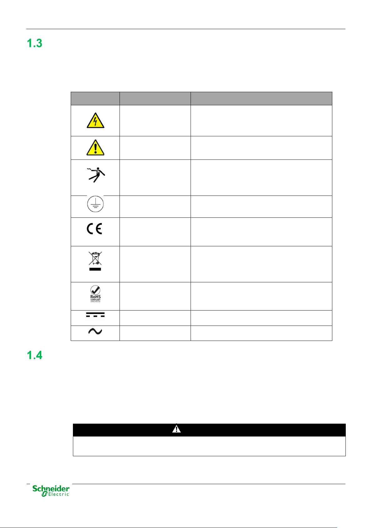
Symbol
Associated Text
Description
IEC symbol associated to a DANGER or
could cause damage to people or death.
Symbol associated with a risk alert. The user
equipment.
ANSY symbol associated to a DANGER or
Protective earth
Associated symbol to the protective ground
This symbol indicates that the equipment has
Electronic device.
This symbol indicates that, at the end of its life,
The equipment has been designed and
Symbol of direct voltage (VDC).
Alternate Voltage
Symbol of alternate voltage (VAC).
DANGER
Devices that handle dangerous tensions are marked with a sticker on the front label (size: 12,5
Symbols and Labels on the Equipment
Before the equipment is installed or commissioned, the user must understand the following
symbols, which may be used on the equipment or referred to in the user documentation:
Table 1 – Symbols
Possibility of electric
chock
Caution, read the
manual.
Possibility of electric
chock
WARNING message indicating that there is an
electrical risk. Failure to follow these instructions
must read the manual before handling the
WARNING message indicating that there is an
electrical risk. Failure to follow these instructions
could cause damage to people or death.
connection
CE Mark
Special instructions
must be follow for
discard it.
Compliant with
RoHS.
connection. See paragraph 1.5.1 in this manual.
been developed in compliance with all
applicable European Directives.
this module must be discarded according to the
WEEE Directive (Waste Electrical and Electronic
Equipment).
manufactured according to RoHS Directive
(Restriction of Hazardous Substances).
Direct Voltage
Installation, Setup and Operation
There are several acquisition blocks in Saitel DR that use high voltages (> 50 V). The user is
responsible to check that the characteristics of each device are adapted and convenient for his
installation. The user should read the instructions of installation before proceeding to the use or
maintenance of the devices.
Not following these instructions can be dangerous for the people and the devices.
mm). This label must be visible all the time while the module is installed on the DIN rail.
Pag 8
Page 9
User Manual – AB_AI
20/03/2020
R&D Digital Seville
WARNING
If this type of cabinet isn't available, a barrier must be installed in order to avoid an accidental
or even can damage to the people or devices.
INFORMATION
Terminals will not be accessible to the user directly once it has made the installation of the
The following products handle dangerous tensions:
• HU_AF: Advanced head unit with acquisition (P/N M503xx3x0x and P/N M503xx4x0x). For
other part numbers, depending on the voltage handled by the equipment connected to the
digital outputs (voltage > 50 V), this module must be marked with an electric risk label. It will
not be marked on factory.
• HU120: High-performance CPU with acquisition (P/N M590xx000x).
• AB_DI: Digital inputs module (P/N: M55520000x, M55530000x and M55540000x).
• AB_DIDO: Input and output digital module (P/N M5722x000x, M5723x000x and M5724x000x).
For other part numbers, depending on the voltage handled by the equipment connected to the
digital outputs (voltage > 50 V), this module must be marked with a electric risk label. It will not
be marked on factory.
• AB_AC: Direct measurements module (P/N M562x0000x).
• AB_DO: This module does not handle high voltages, it will not be marked at the factory. This
module must be marked to inform about the risk when some equipment that manage voltage
higher than 50 V are connected to digital outputs.
It is recommended to install the RTU inside a cabinet with a key. This cabinet only should be
opened by a qualified person.
contact with these dangerous elements. This barrier only should can be removed using a
special tool.
If the barrier has to be removed in order to access to equipment, personnel responsible for the
task must be sure that the barrier is installed again when the task is finished.
While the RTU is accessible for a user, all people must follow all instructions to prevent
electrical risk or discharges.
Not following these instructions can give like result that the device do not work properly
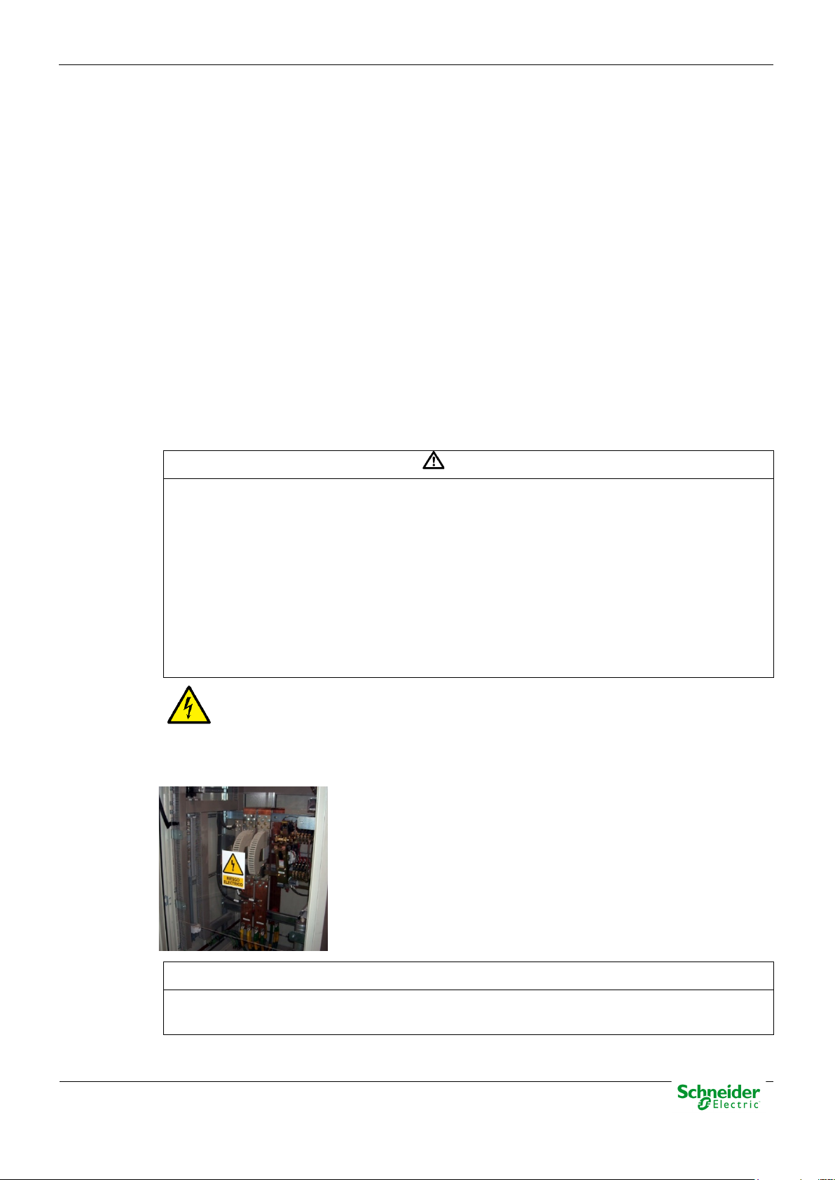
An electrical risk symbol with enough size must be included on the cabinet’s door or
on the barrier.
The following image shows an example:
Figure 1 – Barrier of protection for elements with dangerous voltages.
device. The cabinet will have to remain closed with key or the screen of installed protection.
The cabinet or installation must have a general switch placed just in the cable entry of the
installation (see paragraph 1.7.1)
Pag 9
Page 10
20/03/2020
User Manual – AB_AI
R&D Digital Seville
WARNING
Don’t use a liquid products of cleanliness due to the presence of active parts.
WARNING
that should be disconnected.
WARNING
All devices with high voltage must be disconnected before dismount a module from the DIN rail.
Earthing
For the cleaning of the device it is only necessary using a dry cloth by the surface when it detects
excessive presence of dust or any element deposited on the surface.
Because of the variety of uses of the product, the managers of the application and use of this
device of control will have to take the measures to ensure the fulfillment of all the requests of
security and provision of each application. The requests do reference to the applicable laws,
regulations, codes and standard.
Before energizer the device, it has to be placed to earth properly such as it indicates in sections
1.5.1 and 1.5.2.
When installing the device, ground is the first thing that should be connected and the last one
Saitel can need put to earth for two distinct needs:
• For purposes of electrical safety (Protective Earth, PE).
• Improve the behavior in EMC and derive perturbations to earth (functional Earth).
Electrical Safety
Only qualified personnel, with knowledge about hazards associate with electrical equipment is
allowed to install Saitel DR. In general, the installation will be following IEC 61010-1
recommendations in order to be compliant with this norm.
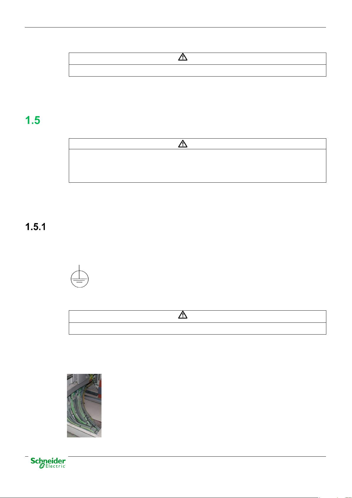
The DIN rail must be installed on a metallic surface. This metallic surface must have
available an M4 screw marked with this symbol. The ground of the cabinet or
installation must be connected to this screw, according to the norm IEC 61010-1.
Saitel DR modules have a metallic enclosure offering protection for isolation faults. Earthing is
done by the metal rail fixing clip.
A dedicated connection with green/yellow wire should be used to assure electric continuity to the
installation protective earth. Section of these wires must be enough in order to support 25 A
(ground bonding test).
Figure 2 – Yellow and Green cable for earthing.
The design and installation of the cabinet is responsible for compliance with all the existing
international and national electrical codes concerning protective grounding of any device.
Pag 10
Page 11
User Manual – AB_AI
20/03/2020
R&D Digital Seville
WARNING
According to Electrical Safety:
INFORMATION
The DIN rail must have terminals of earthing (of yellow and green color) necessary to connect
WARNING
The enclosure ONLY should be removed when is strictly necessary, because this action has a
• The screw for ground must be exclusive for this use.
• The power voltage must be supplied by a power supply that offers double or reinforced
insulation against dangerous voltages.
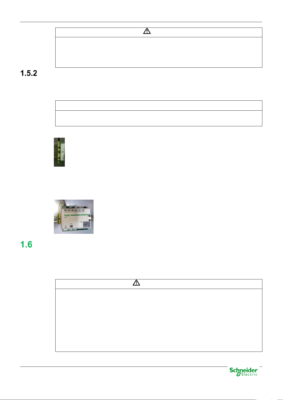
Functional Earth (EMC)
In this case the main rule is that the connection has to do with wires of the lower possible length to
the screen or connection of put to earth nearer. In this case the section of the driver is not notable,
is more, it advises that the use of flat wires or flexible conductive bands for a good behavior EMC.
the terminals of PE (if it is present).
Figure 3 – Terminal for functional earth (EMC).
All Saitel DR modules with power or polarization connector have an exclusive terminal for earthing
EMC. These modules are HU120, HUe, HU_B, HU_A, HU_AF, XU, AB_DO, AB_DIDO and
AB_SER with external polarization.
Figure 4 – Example of earthing for EMC.
Handling Electronic Components
Saitel is susceptible to receive electrostatic discharges during the handling. It is necessary to take
the usual measures to minimize this risk, since serious damage to the equipment can be caused,
which may not be detected immediately but which may affect the reliability of the product.
risk for the equipment:
• Before removing the enclosure, the operator must be equipotential with the equipment.
• Avoid touching the electronic. The board must be always manipulated for the edges.
• If the equipment has to be passed between two persons, both must be equipotential.
• Put the module always on an antistatic surface or on a surface equipotential with you.
• During the storage and transport, the module will remain in the packaging.
Pag 11
Page 12
20/03/2020
User Manual – AB_AI
R&D Digital Seville
Not following these instructions can give like result that the device do not work properly
WARNING
The connection / disconnection switch must be installed in a fixed element (for example the wall
WARNING
This equipment has been designed ONLY for indoor use.
or even can damage to the people or devices.
Technical Specifications for Safety
Protective Elements
The cabinet's engineering and installation must include a general automatic switch next to the
cables' input in the cabinet; once the door is opened, high voltages must be interrupted inside. This
switch must be located at a place which is not accessible by a third person while the operator is
using the boards in the cabinet.
Moreover, the installation will incorporate a circuit breaker of 5A next to the cabinet protecting it
from possible overcurrent in the power supply.
Both switches will be labeled with the symbol O as "Off" and I as “On”.
of the cabinet) and it mustn’t break any earthing wire.
Environmental Conditions
The protection degree of the device is IP20.
If it is necessary for his use in some external surroundings, it has to mount in a cabinet or specific
accommodation that contributes a degree of protection IP54, protected against the dust and water.
The electronic cards of the modules will be able to be tropicalized or no according to the option of
setting chosen. The tropicalized used is the AVR80, of the company ABchimie. It can consult all the
technical information of this type of finishing in http://www.abchimie.com/
Other data to take into account about the environmental are:
• Altitude until 2000 m.
• Operation temperature range: Between -40 ºC and 70 ºC. (IEC 60068-2-1 and IEC 60068-2-2).
• Maximum relative humidity of 95%. (IEC 60068-2-30)
• Degree of pollution II. (IEC 61010-1)
• Overvoltage transitory until levels of Category II. (IEC 61010-1)
Storage Conditions
The continuous exhibition to some high levels of humidity during the storage can cause damages
to the electronic components and reduce the useful life of the device.
.
We recommend that, in the enclosure of storage, the relative humidity do not exceed 50%.
Once that the Saitel devices have been unpacked, recommend that they are energized inside the
three following months. When it installs an electrical device, it has to leave sufficient time for the
acclimatization to the temperature acclimatize of the environment, before the activation. Once the
equipment has been unpacked, it is recommended that it be energized within the following three
months.
Pag 12
Page 13
User Manual – AB_AI
20/03/2020
R&D Digital Seville
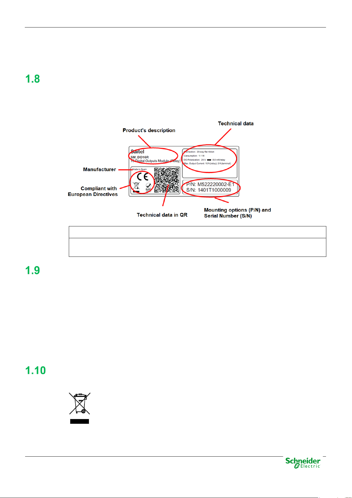
INFORMATION
On the “Technical data” zone, you can see relevant information about the input and output
the other elements, and each one must be recycled according to the local regulation.
•
•
•
Technical Label
Each Saitel product includes a technical label with the following information:
Figure 5 – Technical label.
voltage in the module. Any voltage greater than 50 V must be consider as a high voltage.
Packing and Unpacking
All Saitel modules are packaged separately in their own carton box and shipped inside outer
packaging. Use special care when unpacking the device. Don’t use force.
The design revision and manufacturing options can be determined using the P/N included in the
packaging label on packaging.
After unpacking the device, inspect it visually to be sure it is in proper mechanical condition.
If the product needs to be shipped, the original packaging must be used, including foams and the
carton box. If the original packaging is no longer available, make sure that the packaging used is
according to ISO 2248 specifications for a drop height 1 m.
Decommissioning and Disposal
When the product is marked with this symbol, it means that, at the end of its life
cycle, you mustn't dispose the product together with habitual residues. To avoid the
possible damage to the environment or to the human health that represents the
uncontrolled elimination of residues, please, separate the battery (if there is one) of
•
•
Pag 13
Page 14

20/03/2020
User Manual – AB_AI
R&D Digital Seville
Pag 14
Page 15

User Manual – AB_AI
20/03/2020
R&D Digital Seville
2 General Description of AB_AI
Pag 15
Page 16
20/03/2020
User Manual – AB_AI
R&D Digital Seville
Content
2 GENERAL DESCRIPTION OF AB_AI .................................................................... 15
SAITEL DR PLATFORM ........................................................................................... 17
AB_AI FEATURES ................................................................................................. 17
INTERFACES .......................................................................................................... 18
HARDWARE ARCHITECTURE ................................................................................... 19
Pag 16
Page 17
User Manual – AB_AI
20/03/2020
R&D Digital Seville
WARNING
Please note Saitel DR does not support hot-swapping, that is, module replacements during
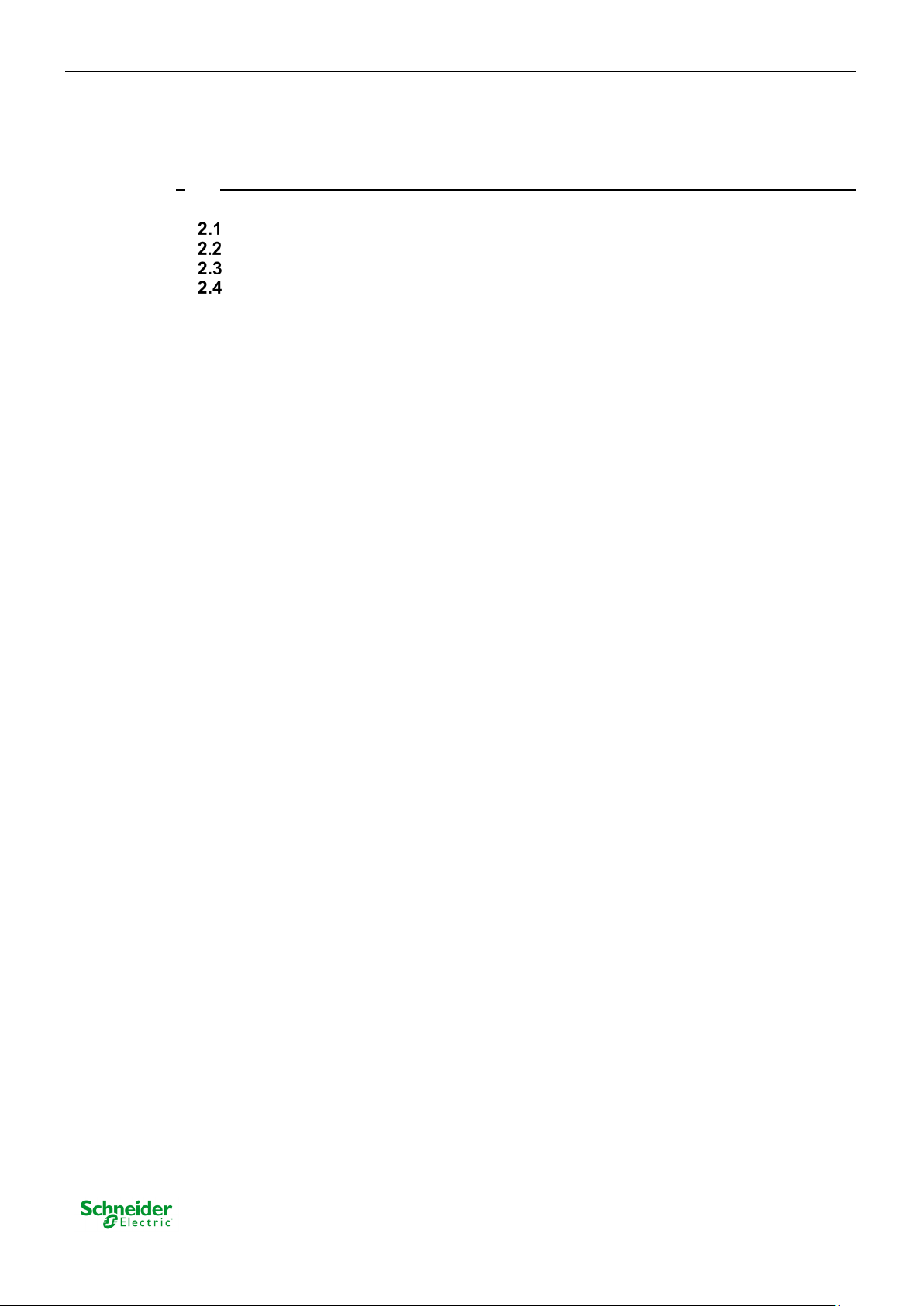
Saitel DR Platform
Saitel DR is a hardware platform by Schneider Electric. It consists of a set of equipment which
have been specifically designed for real-time control and automation applications. Saitel DR is a
high-technology platform which serves Schneider Electric’s business areas.
On this hardware platform, the Baseline Software Platform is installed. This software is used in
Saitel families (Saitel DP and Saitel DR) and other Schneider Electric products.
Other features identifying Saitel DR are:
• A DIN rail is used for the mechanical installation.
• The communication between the controls units integrated in a distributed system is mainly
established by Ethernet.
• The terminal blocks for field-connection are completely built into acquisition blocks.
Figure 6 – Saitel DR.
Saitel DR’s design has been optimized to meet the most demanding requirements of multiple
sectors:
• Safety and reliability requirements for power, gas and water supply, as well as sewage
treatment plants, etc.
• Compliance with electric safety, electromagnetic compatibility, and environmental standards.
• Centralized monitoring and control of geographically-distributed systems which support
hierarchical data acquisition and sharing networks.
• Local monitoring and control with data sharing capabilities of plant-distributed equipments.
• Quick troubleshooting, including the possibility of using programmable automation execution.
operation.
AB_AI Features
The main features of this module are:
• 8 analog inputs using 2 removable terminal blocks. Each terminal allows connecting 4 signals.
• The information is processed before transmitting it to the HU, to do so, it uses a high-resolution
sigma-delta converter.
• Processing of information includes:
Pag 17
Page 18
20/03/2020
User Manual – AB_AI
R&D Digital Seville
o Digital filtering.
o Scaling to engineering units.
o Range limits detection.
o Value change detection.
o Zero value cancellation
• The module is synchronized via a message received from the HU.
• 4 LED indicators are available on the front side.
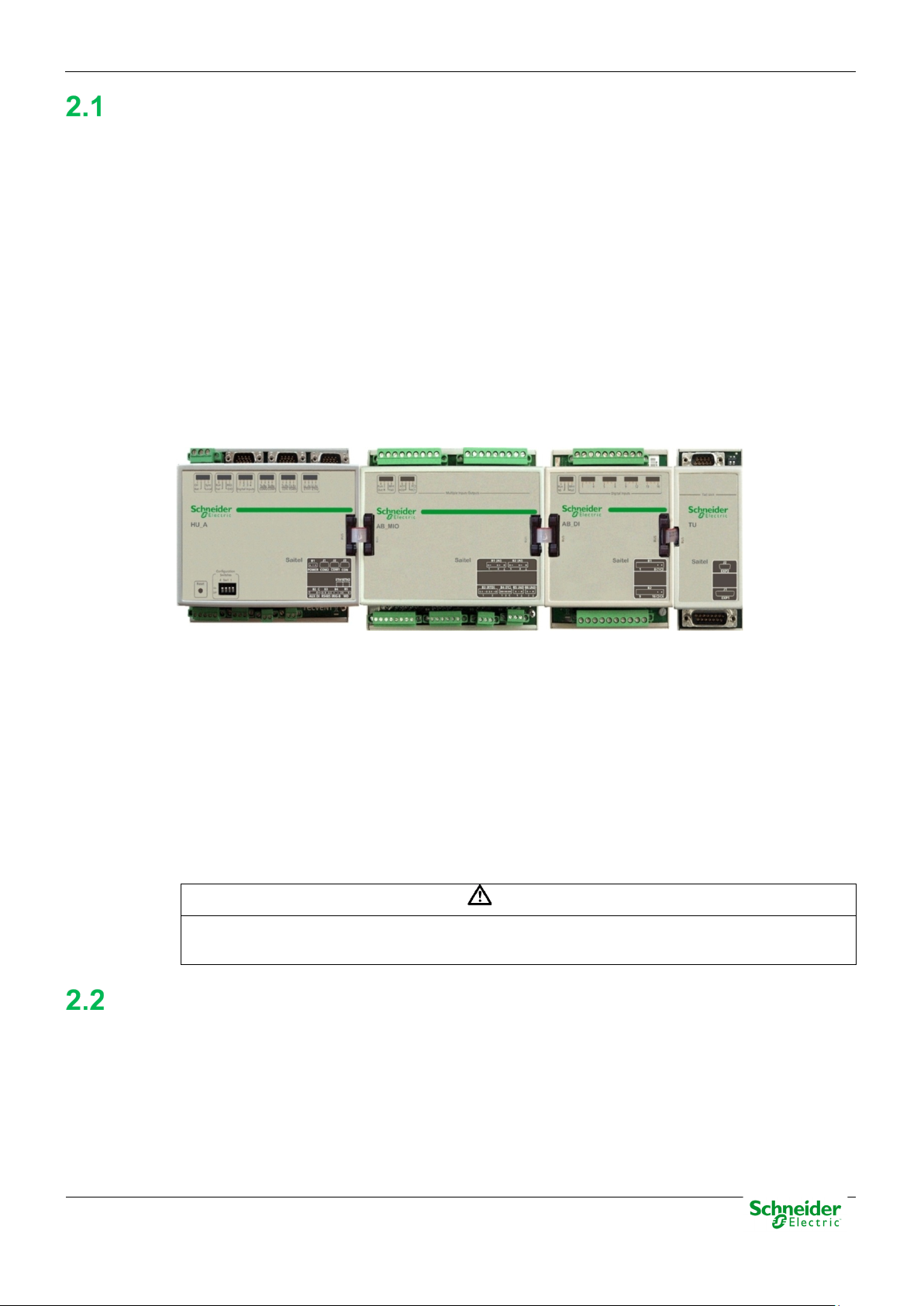
The diagram below illustrates the functional blocks integrated in the AB_AI module:
Figure 7 – Functional block diagram
Analog Inputs
Interfaces
The AB_AI has two terminal blocks labeled as B1 and B2 which allow the connection of 8 analog
inputs (4 per terminal block). The main features of these inputs are:
• Differential type.
• By default, all signals are ready for voltage, but they can be configured for currents using an
external resistor (250 Ω).
• 8-channel multiplexing.
• 16-bits sigma-delta converter.
• Accuracy better than 0.1% at 25 ºC.
• Protections against overvoltage.
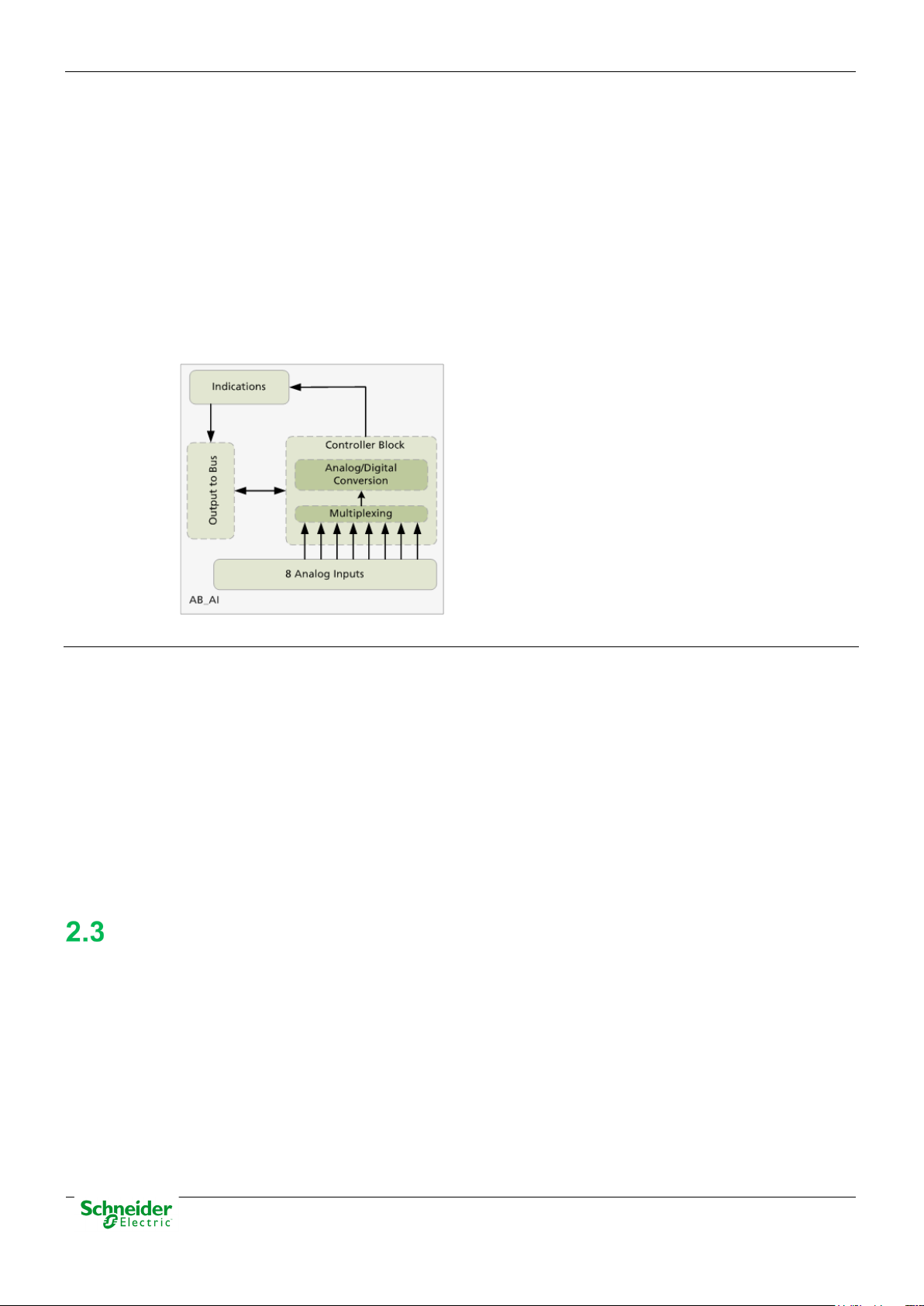
Following interfaces are available in this module:
• 2 removable terminal block to connect one analog input.
• 4 LED indicators.
Figure 8 – AB_AI Module
Pag 18
Page 19
User Manual – AB_AI
20/03/2020
R&D Digital Seville
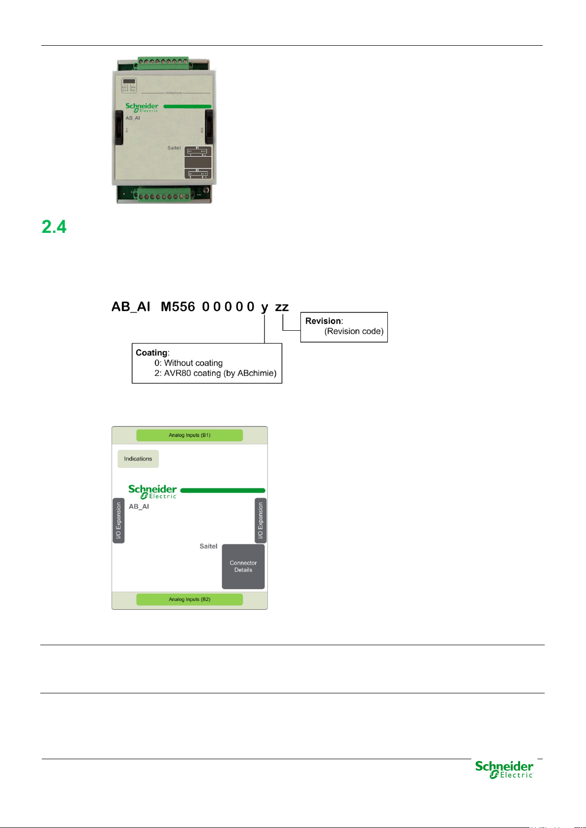
Hardware Architecture
The following P/N describes all available ordering options for this module:
Figure 9 – AB_AI P/N description.
Indicators
The following figure illustrates the AB_AI hardware blocks diagram:
Figure 10 – AB_AI - Hardware block diagram
There are 4 LED indicators on the module’s front panel which provide information about the module
and the features
Analog Inputs (B1 and B2)
There are 4 analog inputs in each terminal. The first 8 pins (from left to right) are related to 4
analog inputs and the last one is used for ground connection.
Pag 19
Page 20

20/03/2020
User Manual – AB_AI
R&D Digital Seville
3 Physical Mounting & Installing
Pag 20
Page 21

User Manual – AB_AI
20/03/2020
R&D Digital Seville
Content
3 PHYSICAL MOUNTING & INSTALLING ................................................................ 20
ITB INSTALLATION ................................................................................................. 22
HANDLING ...................................................................................................... 22
LOCATION IN THE ITB ..................................................................................... 22
POWER SUPPLY REQUIREMENTS .................................................................... 22
MOUNTING PROCEDURE ................................................................................. 22
WIRING AB_AI ...................................................................................................... 23
WIRING RECOMMENDATIONS .......................................................................... 24
ANALOG INPUT CONNECTION .......................................................................... 24
LED INDICATORS ................................................................................................... 25
Pag 21
Page 22

20/03/2020
User Manual – AB_AI
R&D Digital Seville
DANGER
Depending on the devices connected to the module AB_AI, could exist hazard of electric
WARNING
Electrostatic discharges may damage semi-conducive devices within the module.
WARNING
It is important to assure that handling is always done while the ITB elements are unpowered.
ITB installation
Handling
chock, electric arc or burns. For any of these cases, follow these instructions:
• Only qualified operator should install this equipment. Such work should be performed only
after reading this entire set of instructions and checking the technical characteristics of the
device.
• NEVER work alone.
• Turn off all power supplying this equipment before working on or inside it. Consider all
sources of power, including the possibility of back feeding.
• Always use a properly rated voltage sensing device to confirm that all power is off.
• Start by connecting the device to the protective ground and to the functional ground.
• Screw tight all terminals, even those not in use.
Failure to follow these instructions will result in death or serious injury.
To avoid electrostatic damage, the following precautions must be strictly followed:
• Do not touch the bus connector pins.
• If unused, keep the modules in the antistatic bag.
Location in the ITB
Saitel DR modules cannot be placed at any position in the ITB. Some of them, such as the head
unit, the termination (TU or BT), the expansion (XU) and the communications module (AB_SER)
must be installed in a specific position in the ITB.
All AB_AI modules will always be placed between two termination blocks. The type of termination
block will depend on the row position within the ITB (HU, TU, XU or BT).
Power Supply Requirements
The main power is supplied by the HU through the bus. The maximum power requirement for each
AB_AI module is:
1
• Main power supply: Basic consumption
Mounting Procedure
All Saitel DR modules have a DIN-rail bracket at the rear side that allows mounting on a DIN rail.
1
Basic consumption and Maximum current per signal values are indicated in the technical specifications table at
the end of this manual.
Pag 22
Page 23

User Manual – AB_AI
20/03/2020
R&D Digital Seville
Figure 11 – Mount bracket on DIN rail.
The mounting procedure is described below:
• Switch off the power supply.
• Attach the module’s rear bracket on the upper DIN rail.
• Press the lower front panel gently until a click confirms that the bracket is fit on the rail.
• Verifying the module is anchored firmly to the rail, although lateral movement is possible.
Figure 12 –
Saitel DR module on a DIN rail.
The module is dismounted from the DIN rail as follows:
• Switch off the power supply.
• If necessary, disconnect the bridge(s) connecting the module to the system bus.
• Holding the module by the front panel, push the upper metal tab downward. The user can also pull the tab down
using for example a screwdriver as shown in the next figure.
• Figure 13 – Remove module.
•
•
• Pressing the tab, remove the module from the lower DIN rail.
• Once detached, the module can be removed easily.
Wiring AB_AI
The AB_AI analog inputs are differential, so there is no common terminal. Each terminal block
includes 4 pairs of signals which correspond to the 4 analog inputs.
Pag 23
Page 24

20/03/2020
User Manual – AB_AI
R&D Digital Seville
INFORMATION
Current inputs require a 250Ω resistor and a 0.1% precision between the two input
terminals.
This figure illustrates the pins arrangement in the AB_AI screw terminals:
Figure 14 – B1 and B2 terminal blocks wiring.
Wiring Recommendations
The following table shows several wiring recommendations for signals and polarization:
Analog inputs 7 mm
Analog Input Connection
Both B1 and B2 have 4 terminals for signals. The field inputs are voltage-free NO (Normally open)
contacts.
Figure 15 – B1 and B2 terminal blocks wiring.
2.5 mm²
13 AWG
0.5 Nm Copper
Type of wire
The 8 signals wiring in each terminal block is described below:
Figure 16 – Analog inputs wiring.
Pag 24
Page 25

User Manual – AB_AI
20/03/2020
R&D Digital Seville
LED
Status
Description
Recommended action
LED Indicators
The AB_AI module has the following indicators on the front panel:
Figure 17 – LED indicators.
Run
Out R
Fail
AB_AI LED provide the following information to the operator:
Table 1 - AB_AI - LED indicators meaning
Module working properly.
Module not in acquisition mode.
A signal is out of range. Check the range of the signals
Signals are in range.
Module not configured or in abnormal state.
No fault has been detected in configuration or
hardware.
Failure in EEPROM.
The module wasn’t included into the
configuration, the module doesn't have an
address or according to the loaded
configuration, the type of the module is wrong.
Check the configuration loaded in the HU. The
module must be addressed and with the
correct type (AB_AI).
Mnt
The module is in maintenance (Flashing,
addressing, ...)
The module is in operation.
Pag 25
Page 26

20/03/2020
User Manual – AB_AI
R&D Digital Seville
4 Configuration & Maintenance
Pag 26
Page 27

User Manual – AB_AI
20/03/2020
R&D Digital Seville
Content
4 CONFIGURATION & MAINTENANCE .................................................................... 26
ITB CONFIGURATION .............................................................................................. 28
AB_AI CONFIGURATION ........................................................................................ 30
INFORMATION OF LOCAL ACQUISITION ............................................................. 31
AB_AI SIGNALS .............................................................................................. 32
LOCAL ACQUISITION COORDINATES ................................................................ 32
INFORMATION IN THE TABLE ANALOG .............................................................. 33
SIGNAL CALIBRATION ............................................................................................ 34
SIGNAL CALIBRATION USING A BASIC HU ........................................................ 34
SIGNAL CALIBRATION USING A HU_A OR HU_AF ............................................ 36
SIGNAL CALIBRATION USING A HUE ................................................................ 37
MAINTENANCE OF MODULE VIA WEB ..................................................................... 39
WEBAPP VS WEBTOOL .................................................................................. 39
USING WEBAPP ............................................................................................. 39
USING WEBTOOL ........................................................................................... 45
FIRMWARE UPDATE ............................................................................................... 49
Pag 27
Page 28

20/03/2020
User Manual – AB_AI
R&D Digital Seville
INFORMATION
To perform the operations described in this chapter, the user must be familiar with the Easergy
ITB configuration
Builder tool. Otherwise, please refer to the tool's manual.
In the Workspace of Easergy Builder, create a new RTU using button or pressing right button
of the mouse in an empty area of the rtus tree:
Figure 18 – Adding a new RTU.
Pressing button next to the graphical ITB, you can add, remove or change the I/O modules
included on the default configuration.
The user needs understand some basic concepts about Saitel DR before configuring the
acquisition:
• An ITB is a set of acquisition blocks connected to a CPU (HU).
• An Acquisition Block or AB is a Saitel DR input/output module.
• Each acquisition block is allocated to a unique address in the ITB, the Node Number; this
number identifies both the module and its type.
• The procedure AAP (Automatic Addressing Procedure) is performed by the operator
every time an AB module is added, deleted, replaced or moved inside the ITB. It can be
launched manually or automatically depending on the configuration switches of the HU
(consult user manual of the HU).
Figure 19 – ITB.
Pag 28
Page 29

User Manual – AB_AI
20/03/2020
R&D Digital Seville
The number between parentheses next to each module's name is the node number. You can
select an AB and use buttons to change its physical position.
When “Auto Address” box is checked (by default), if you reorder, add or delete an AB, all
addresses are automatically recalculated matching their physical position in the rail. Address
number 1 is assigned to the AB closest to the HU module (for HU_AF or HU_BI, address number 1
will be attached to the HU itself).
If “Auto Address” box is unchecked, modules will retain the allocated address, ignoring any
changes made. If rechecked, the following message will appear:
Figure 20 – Auto Address.
Select an AB (click on the AB image) and use button to remove it. Use button to add a new
AB. Select the type of AB in the following window:
Figure 21 – Adding an AB module.
If “Auto Address” is checked, you can add several AB at one time. This window allows selecting
the quantity of modules to be added. If “Auto Address” in unchecked, you only can add one AB
each time and you have to select the address to be assigned.
To create a new configuration, select RTU in the tree and pulse right button of the mouse or use
button.
Figure 22 – Adding a configuration.
Pag 29
Page 30

20/03/2020
User Manual – AB_AI
R&D Digital Seville
If the field "Create acquisition points defined in the RTU" is marked, all points of the local
acquisition of the acquisition blocks included in the default acquisition configuration associated with
the RTU will be included in coreDb.
For example, if a HUe has an ITB with an AB_AI module, if "Create acquisition points defined in
the RTU", 8 analog inputs signals will be included in the Analog table.
Finally, the new configuration will appear in the RTUs tree.
Access to the configuration edition clicking on the configuration name in the tree:
Figure 23 – Configuration edition
Double click on the claq Device open the window to configure/modify the ITB.
Selecting the module AB_AI, you can configure each field signal
Figure 24 – Changing the ITB configuration.
Other buttons in this window are explained in the user manual of Easergy Builder.
AB_AI Configuration
The local acquisition Device for Saitel DR is named “claq”. The main functionality of the Local
Acquisition Device Controller is supporting the communication between the inputs and the outputs
managed by the acquisition blocks and coreDb points.
The first step to configure the acquisition settings is to assure that the ITB in the graphical interface
is according to the system. Each module must be addressed according its position in the ITB.
Pag 30
Page 31

User Manual – AB_AI
20/03/2020
R&D Digital Seville
INFORMATION
The graphical interface does not take into account if the ITB is assembled in one or multiple
rows. The modules should always be added in the adequate order, regardless the number of
TU-XU modules that we have installed.
Figure 25 – Configuring local acquisition for Saitel DR.
Information of Local Acquisition
The following figure shows the relationship between the field information received by the AB_AI
module and the related points in coreDb:
Figure 26 – Field signals and points in coreDb.
Pag 31
Page 32

20/03/2020
User Manual – AB_AI
R&D Digital Seville
AB_AI signals
The following figure shows the configuration panel when the ITB is composed by an HUe and one
AB_AI module with address 1:
Figure 27 – AB_AI field signals.
Select the module in the ITB and all its field signals are shown (marked in red).
The first position of each row corresponds with the signal’s description (AI_PNT_1 ... AI_PNT_8).
In coreDb, each signal will be identified using its coordinate. (see paragraph 3.2.2).
Each signal has the following associated information:
• EMin: Minimum value expressed in field units (from -32768 to 32767).
• EMax: Maximum value expressed in field units (from -32768 to 32767).
• Rng: Voltage range expressed in engineering units (0/5 V, -5/5 V, 0/20 mA, -20/20 mA, and
4/20 mA).
• Filt: Mobile measuring filter (expressed as a percentage value, 0 - total filtering and 100 - no
filtering).
• Zero: Zero cancellation (expressed in scaled values)
Local Acquisition Coordinates
Each digital input is identified in coreDb by a name (it is stored in the field Description), but this
name is only used for information purpose. coreDb uses the signal’s coordinate in order to identify
a field signal.
A claq coordinate is a numerical identifier of 10 digits with the following structure:
Where:
• 1: First digit of the coordinate. In local acquisition signals, it must always be 1.
• XXX: Number that identifies the acquisition block. For the HUe signals, it will always be 000.
For the rest of the ABs, this number will correspond with the address of the module.
1XXXYYZZZZ
Pag 32
Page 33

User Manual – AB_AI
20/03/2020
R&D Digital Seville
• YY: Type of signal. For digital input could be:
o 02: Simple digital input.
o 03: Count.
o 07: Double digital input.
• ZZZZ: Position of the signal in the module.
Information in the Table Analog
Each AB_AI signal is associated to a coreDb register in the analog table using its claq coordinate
as source:
Figure 28 – Information of analogical inputs in CoreDb.
These points and other diagnostic points (D001_COMM_DIAG and D001_HW_DIAG) can be
created automatically when the module is included in the ITB, but they can be created manually
using the claq’s wizard.
In order to include a point manually, please create a new point, select claq as Source Device, click
right-button on the field Source Device and select Launch Point wizard:
Figure 29 – Point wizard.
Pag 33
Page 34

20/03/2020
User Manual – AB_AI
R&D Digital Seville
INFORMATION
Select the module in which it wants to create these points and then select the point to be created.
Only not created point will be shown in the list.
The following point can be added for a AB_AI module:
• Status, Source Coordinates:
o Diagnostics point:
• Analog, Source Coordinates:
o Analog Inputs: Analog inputs, depend on the configuration performed.
Signal Calibration
The AB_AI analog inputs are calibrated in factory. Nevertheless, the user may calibrate each signal
to meet the environment requirements.
COMM_DIAG: Status of the communication with the HU. 0 “Communication
FAIL”, 1 “Communication OK”.
HW_DIAG: Hardware diagnostic. 0 No problem detected, 1 Problem
detected in the hardware.
• The user must assure that the calibration device is similar to the device recommended by
Schneider Electric, in particular the calibrator Fluke 725. The device should be able to generate
voltages ranging from 0V to 10V with a precision lower than 0.1%.
• Signal calibration can be performed in the field, while the ITB is under a normal data acquisition
state. During calibration, all modules will operate normally, except for the module under calibration.
The calibration method depends on the HU type which controls the ITB. If the CPU is an advanced
HU (HU_A, HU_AF), Saitel Webtool is used to calibrate. If the CPU is a Hue, Saitel WebApp is
used. When the CPU module is a basic HU (HU_B), the calibration process is performed using the
console.
The calibration is done separately for each channel.
Signal Calibration Using a Basic HU
1. The user needs to connect the PC to the HU module through the CON port (console channel).
For further details about the connection, please refer to the CPU manual.
2. For each analog input, the user must execute the “claqCalAi N C” command, where N refers
tclao the AB_AI module's number within the ITB (can be obtained by entering the “claqShow”
command in the console) and C refers to the signal number within the module, where
1<=C<=8.
3. After executing the calibration command, for example on the 2
(signal 2) of the module number 1, the following message will appear:
nd
signal of the B1 terminal block
4. When the calibrator is connected to terminals AI2+ (red cable) and AI2- (black cable), the
system will wait for it to supply 0V. Then, the user needs to press any key. Subsequently, the
system asks the user to wait while specific calculations are made.
5. Once a 0V level is registered, the system requests a 5V level voltage to be injected and to
press any key:
Pag 34
Page 35

User Manual – AB_AI
20/03/2020
R&D Digital Seville
NOTICE
6. The system will repeat the operations and calculations for this voltage level. Once finished, it
will display a message to inform that the analog input has been calibrated:
The calibration values depend on the signal range assigned in the configuration tool (see section
3.2).
For example, if the input 1 of the AB_AI module, which is in the position 1, is configured in the
range 0/20 mA, the messages exchanged with the user during the calibration process are:
In the case of calibrating current inputs, it will be necessary to place a 250Ω resistor between the
positive and the negative pin, so that by injecting current with the calibrator, the voltage between
the two input terminals is lower than 5V.
Factory calibration values can be restored individually for each signal at any time. To do so,
execute the “claqRestCalAi N C” command, where N refers to the module number and C refers to
the signal number in the module. For example, to restore the factory values for the previous signal
(input 1), follow the procedure below:
• It should be noted that even if the signal is configured for current (0/20 mA), the factory
calibration is done for voltage values, and these are the retrieved values. Therefore, the resistor
tolerances, which convert current to voltage, are not calibrated.
• Schneider Electric recommends a 250Ω resistor with 0.1% tolerance in order to maximize the
resolution of the analog to digital converter
Pag 35
Page 36

20/03/2020
User Manual – AB_AI
R&D Digital Seville
Signal Calibration Using a HU_A or HU_AF
If the CPU is a HU_A or HU_AF, to calibrate AB_AI, Saitel WebTool must be used.
In WebTool, go to Bins section and click on “claq”. You will see a table with the correspondent
signals.
Figure 30 – Saitel WebTool Menu.
For example, following picture shows a tab corresponding to an AB_AI module.
Figure 31 – Claq Device in Saitel WebTool.
To calibrate a specific AB_AI module, press “Calibrate” button on the table. Then, the following
screen appears:
Figure 32 – AB_AI module calibration.
Each input must be calibrated separately, by pressing the “Start” button which is associated to
each signal in the “Calibration” column.
Pag 36
Page 37

User Manual – AB_AI
20/03/2020
R&D Digital Seville
When calibration starts, the following message is shown:
When the calibrator is connected to terminals AI1+ (red cable) and AI1- (black cable), the system
will wait for the calibrator to supply 0 V. Then, press “Ok”. Subsequently, the system asks the user
to wait while the input is calibrated for 0 V.
Then, the following message is shown:
As described for the previous step, supply 5 V through the calibrator and then press “Ok”. The
system will start the calibration for this voltage level.
When the operation finishes, the following message will appear:
The calibration values depend on the signal range assigned in Easergy Builder.
Factory calibration values can be restored at any time for individual signals. To do so, press the
“Restore” button associated to the channel in the table. You will be prompted to confirm or cancel
the operation.
Signal Calibration Using a HUe
If the CPU is a HUe, to calibrate AB_AI, Saitel WebApp must be used. The recommended web
browser is Google Chrome (version 67.0.3396.99).
In WebApp, go to Maintenance section and click in “Acquisition”. You will see a table with the
correspondent signals. If the permissions set for the user allows it, these points van be calibrated.
Figure 33 – Saitel WebApp Menu.
Pag 37
Page 38

20/03/2020
User Manual – AB_AI
R&D Digital Seville
For example, following picture shows a tab corresponding to a AB_AI module. All its signals are
displayed with the value and quality information.
Figure 34 – AB_AI module calibration.
To start the calibration of an analog input, just click on the “calibrate” button for the signal to
calibrate. A window will pop with the instruction that the user must follow. Please take into account
that if the point has no good quality or it is blocked, calibration will not start.
Press “Yes” to continue or “No” to cancel the process.
If the analog point cannot be calibrated, following message will be shown:
Pag 38
Page 39

User Manual – AB_AI
20/03/2020
R&D Digital Seville
INFORMATION
WebApp has been designed to work only with cybersecurity brick. At now, it can be used only
Maintenance of Module via WEB
WebApp Vs WebTool
WebApp and Webtool are remote user interfaces for consulting, monitoring and maintenance
tasks. Once the username and password have been entered, you can access to the main window
and, depending on the web tool, several sections are available.
with HUe. HU_A and HU_AF use Webtool, while HU_B doesn’t allow a remote connection using
a webserver.
When use WebApp, the following message is shown previously to access the tool:
Figure 35 – Disclaimer information.
Please, read this information and take it into account.
In this manual, only the information about AB_AI is shown. For more information about these tools,
please, consult the user manual for each one.
Using WebApp
Saitel WebApp has an access control that allows differentiating the users who are able to connect.
To get the window access, please write https://< CPU IP address> in the navigation address bar.
Figure 36 – Access screen
Write the Username and Password in orfer to access the webAppp’s mains window:
Pag 39
Page 40

20/03/2020
User Manual – AB_AI
R&D Digital Seville
This screen contains 5 menus:
• Home
Home tab
• Monitoring & Control
• Diagnostic
• Maintenance
• Settings
Select Home in the main toolbar and the following information is shown.
Figure 37 – Home view.
Pag 40
Page 41

User Manual – AB_AI
20/03/2020
R&D Digital Seville
S
ome of this information can be filled in by the user.
• Device Information. It is possible to add the names of the operators who have used or
configured the equipment or a specific custom note that can be viewed each time a connectio
i
s established to this RTU. This information can be changed using button “Edit”, next to “Devic
i
nformation”.
• Location. The GPS coordinates for the RTU location (place, latitude, longitude, and altitude)
should be entered here by the installer. Location is not set automatically. The image must
i
ncluded manually by clicking button on the map.
be
n
e
• Image associated to the RTU. It could be useful to include a location map corresponding to t
G
PS coordinates. Use button on the graphic zone to do it.
• Notes. This zone allows the user to include notes that are shown to other users. Use butt
• Factory information: This zone shows the manufacturer, model and the version of t
software loaded on the HU module. Using button next to the text “Factory Information”, it is
also possible to include an image of the particular RTU or CPU for identification purposes.
This screen contains other menus:
• Monitoring & Control
• Diagnostic
• Maintenance
• Settings
This manual only includes relevant information for AB_AI. For more information about webApp,
please, consult the webApp user manual.
Monitoring and Control
This menu is used to monitor and control the information regarding to system status and coreDb
points.
t
oo add new notes.
he
on
he
Select “Monitoring & control System information” and the following information the system is
displayed or not depending on whether the corresponding monitoring point was included or not in
coreDb. In the following image, for each data, the supervision point that must be included in
coreDb is indicated in a blue square.
Pag 41
Page 42

20/03/2020
User Manual – AB_AI
R&D Digital Seville
Figure 38 – Monitoring and Control view – System information
Please take into account that the correspondent supervision points must be installed, otherwise,
you will see a warning like the one in the example above (PLC information not available).
For an AB_AI module, the showed points are the followings:
Figure 39 – Monitoring and Control – Status.
Figure 40 – Monitoring and Control – Analog.
Pag 42
Page 43

User Manual – AB_AI
20/03/2020
R&D Digital Seville
For all types of points, each page has the same format. If the user locks the signal and click in
in the “value” column, the value of the correspondent signal can be changed.
If the user locks the signal and click in in the “quality” column, the value of the correspondent
signal can be changed.
Each code of quality bit has a different meaning. See next tables to know the description of each
one.
Table 2 - Local quality bits
Values (Hexadecimal) Description
0x00000000 OK
Pag 43
Page 44

20/03/2020
User Manual – AB_AI
R&D Digital Seville
NOTICE
If more than one error is detected for a signal, the hexadecimal value monitored for quality bits
been a carry on a counter or a roll-over. The value 0x00000003 would appear monitored.
Values (Hexadecimal) Description
0x00000001 There has been an overflow
0x00000002 There has been a carry on a counter or a roll-over.
0x00000004 There has been a counter adjustment.
0x00000008 Excessive changes in a digital input.
0x00000010 Locked Point (blocked)
0x00000020 Point manually replaced (manual)
0x00000040 The point has not yet been written into the database (No refresh)
0x00000080 Invalid value (Error)
0x00000100 The value of the item has exceeded Highest Limit Alarm.
0x00000200
The value of the item has exceeded High Limit Alarm.
0x00000400 The value of the point has fallen down of Low Limit Alarm.
0x00000800
The value of the point has fallen down of Lowest Limit Alarm.
0x00001000 Invalid time.
Table 3 - Quality bits from the Device
Values (Hexadecimal) Description
0x00000000 OK
0x00010000
0x00020000
0x00040000
0x00080000
0x00100000
0x00200000
There has been an overflow.
There has been a carry on a counter or a roll-over.
There has been a counter adjustment.
Excessive changes in a digital input.
Locked Point.
Point manually replaced.
0x00400000
0x00800000
The point has not yet been written into the database.
Invalid value.
0x10000000 Invalid time.
will result from the sum of all. For example:
0x00000001 indicates that an overflow has occurred and 0x00000002 indicates that there has
Pag 44
Page 45

User Manual – AB_AI
20/03/2020
R&D Digital Seville
Using WebTool
Saitel Webtool is the tool used for maintenance and monitoring of Saitel RTUs which is supplied
with the baseline software platform. The values of all the coreDb signals in real-time can be
monitored through the Saitel Webtool as well as the quality data related to these values.
Saitel Webtool has an access control that allows differentiating the users who are able to connect.
To get the window access, please write https://< CPU IP address> in the navigation address bar.
If the browser has been correctly configured, and the remote equipment is connected to the PC,
the login window will prompt:
Figure 41 – Login window of Saitel Webtool.
nce the username and the password are introduced in the login window, the main workspace is
O
displayed:
Figure 42 – Initial screen of Saitel Webtool.
This window shows:
• Information about the user who opened the session (Login: admin).
• Button “Exit” in order to close the current session.
• It is possible to select the language through the field “Language”.
• The main menu is located on the left side of the screen. Each button gives access to all t
nformation of the RTU:
i
he
o Information: General information about the CPU configuration.
Pag 45
Page 46

20/03/2020
User Manual – AB_AI
R&D Digital Seville
o Monitoring: Gives access to the coreDb tables and the values for each register
and field.
o Bins: Gives access to the devices that have been configured in the RTU.
Information
o Network configuration: Gives information about the physical devices an
r
ooters.
Clicking Information on the main menu, you can see general information about the system.
The following real-time information can be monitored on this menu:
• System’s Configuration
• Hardware Status
• Synchronization Status
• Software Versions
• Figure 43 – Information section
d
Monitoring
The top area of the screen includes the following information for any signal type (go to “Monitoring
Status”, “Monitoring Command”, “Monitoring Analog” or “Monitoring Setpoint”):
For each kind of modules, the information will be included in different tables. In the case of the
AB_AI module, the information for the acquisition points can be found in the Status and Analog
screen.
In the status table, two signals are automatically created.
COMM_DIAG: CPU diagnosis communication variable. 0 the module cannot communicat
w
ith the CPU. 1 the module is communicating properly with the CPU.
e
HW_DIAG: Auto diagnosis hardware variable. 0 the module is correct. 1 the module has some
hardware problem.
Figure 44 – Status monitoring screen.
Pag 46
Page 47

User Manual – AB_AI
20/03/2020
R&D Digital Seville
NOTICE
If the value of the quality bit associated to the signal is “Unrefreshed” (0x00000040) or “Invalid”
(0x00000080), the signal value will be “???”.
In the analog table, the analog acquisition points can be monitored.
Figure 45 – Analog monitoring screen.
The information available for all types of signals is the following:
• Point name: Signal's name in coreDb.
• Value: Current value of the signal. This value is retrieved from the signal’s source and it is
updated in Saitel Webtool according to the refresh period specified in the RT field.
• QF: Current quality flags of the value displayed for this signal
Clinking in “Set”, the value and the quality flag can be modified.
Figure 46 – Set Value screen.
Pag 47
Page 48

20/03/2020
User Manual – AB_AI
R&D Digital Seville
Each code of quality bit has a different meaning. See next tables to know the description of each
one.
Table 4 - Local quality bits
Values (Hexadecimal) Description
0x00000000 OK
0x00000001 There has been an overflow
0x00000002 There has been a carry on a counter or a roll-over.
0x00000004 There has been a counter adjustment.
0x00000008 Excessive changes in a digital input.
0x00000010 Locked Point (blocked)
0x00000020 Point manually replaced (manual)
0x00000040 The point has not yet been written into the database (No refresh)
0x00000080 Invalid value (Error)
0x00000100 The value of the item has exceeded Highest Limit Alarm.
0x00000200
The value of the item has exceeded High Limit Alarm.
0x00000400 The value of the point has fallen down of Low Limit Alarm.
0x00000800
The value of the point has fallen down of Lowest Limit Alarm.
0x00001000 Invalid time.
Table 5 - Quality bits from the Device
Values (Hexadecimal) Description
0x00000000 OK
0x00010000
0x00020000
There has been an overflow.
There has been a carry on a counter or a roll-over.
Pag 48
Page 49

User Manual – AB_AI
20/03/2020
R&D Digital Seville
NOTICE
If more than one error is detected for a signal, the hexadecimal value monitored for quality bits
been a carry on a counter or a roll-over. The value 0x00000003 would appear monitored.
0x00040000
0x00080000
0x00100000
0x00200000
0x00400000
0x00800000
0x10000000 Invalid time.
will result from the sum of all. For example:
0x00000001 indicates that an overflow has occurred and 0x00000002 indicates that there has
Firmware Update
There has been a counter adjustment.
Excessive changes in a digital input.
Locked Point.
Point manually replaced.
The point has not yet been written into the database.
Invalid value.
Once the ITB is configured, the HU module (HU_A or HU_B) already knows the type of acquisition
blocks that are been installed and their corresponding addresses.
To update the software of the AB_AI module, you need:
• A console connection with the HU.
• AB_AI module must be correctly addressed and working fine in the ITB (LED Run must be
blinking).
• AB_AI.bin file with the new version. This file must be available in the flash folder of the HU. If
not, you can contact Schneider Electric in order to ask for it. Use an SFTP client and transfer
this binary file into the HU flash folder.
The console tool can be executed using any commercial tool for serial or SSH connection. In this
manual, PuTTy software is used.
Open a serial connection as follow:
Figure 47 – Putty configuration.
Pag 49
Page 50

20/03/2020
User Manual – AB_AI
R&D Digital Seville
INFORMATION
If the baseline includes the cybersecurity brick, you need to login in the console with Installer.
for more information.
Module
File
Command
Description
INFORMATION
Console commands are case-sensitive, and quotation marks must be included.
SSH connection via Ethernet can be used too. More information about the console use in the HU
user manual. In the following picture, HUe is used as CPU:
Figure 48 – SSH connection.
No other user has permissions to execute this operation. Please, consult the HU user manual
If the file AB_AI.bin is available in the flash folder, use one of the following commands to upgrade
the software of AB_AI modules:
Table 6 – Upgrading AB_AI software.
All modules *.bin claqUpgrade “all” It updates all the acquisition AB
addressed in the ITB. You need to
use the adequate file for each block.
By position AB_AI.bin claqUpgrade “<position>” It updates the module AB_AI with
the <position> address.
AB_AI AB_AI.bin claqUpgrade “all AB_AI” It updates all the AB_AI modules
installed in the ITB.
Pag 50
Page 51

User Manual – AB_AI
20/03/2020
R&D Digital Seville
After running the command, the console will show some messages indicating the process status.
Finally, if no problem is found, we will have updated the firmware of the modules.
Pag 51
Page 52

20/03/2020
User Manual – AB_AI
R&D Digital Seville
5 Technical Specifications Table
Pag 52
Page 53

User Manual – AB_AI
20/03/2020
R&D Digital Seville
• ±20 mA / 0 - 20 mA / 4 - 20 mA
Ordering Options
CE Mark
LVD – Low Voltage Directive
Directive 2014/35/UE
EMC – Electromagnetic Compatibility
Directive 2014/30/UE
RoHS 2
Directive 2011/65/EU, according to RD 219/2013
Equipment
Verification of Lead, Cadmium, Mercury, Chrome
and Bromine
Cold - EN 60068-2-1:2007
-20ºC during 16h (100h)
Dry heat - EN 60068-2-2:2007
+80ºC during 16h (100h)
Damp heat - EN 60068-2-30:2005
25-60ºC with 95%RH during 24h
Features
Hardware Signal type. Differential
Input type Voltage from factory
Current, using an external resistor (250 Ω)
Converter 16-bits sigma-delta
Accuracy Better than 0.1% at 25 ºC
Input impedance 200 kΩ
Voltage tolerance in common mode > 15 V
Field connection. Terminal / Flat ribbon.
Consumption 0.6 W
Weight 427 g
Dimensions 129 x 94 x 60 mm
Protection Overvoltage
Software Processing Digital filtering.
Scaling to engineering units.
Range limits detection.
Value change detection.
Zero value cancellation.
Common mode rejection ratio. 90 dB
Parameterization Configurable range by channel:
• ±5 V
DC
/ 0 - 5 VDC.
Standards, Directives and
harmonized norms.
WEEE – Waste Electrical and Electronic
RoHS Directive 2011/65/UE
Environmental tests
Directive 2012/19/UE according to RD 110/2015
Pag 53
Page 54

20/03/2020
User Manual – AB_AI
R&D Digital Seville
EMC Directive
EN 60870-2-1 (1996)
IEC/TS 61000-6-5 (2015)
EN 55022:2006 + A1:2007
From 30 to 1000 MHz (Class A)
EN 55022:2006 + A1:2007
From 0.15 to 30 MHz (Class A)
EN 61000-4-2:2009
By air ±8 kV and by contact ±6 kV (Level 3)
EN 61000-4-3:2006 + A2:2010
From 80 to 2700 MHz (Level 3).
Power port: ±4 kV, 5kHz.
I/O ports: ±4 kV 5kHz (Level 4).
Power: ±4 kV symmetric and asymmetric (Level 4)
I/O: ±4 kV CM, ±2 kV DM
EN 61000-4-6:1996 + A1:2001
10 V
RMS
0.15-80MHz 80% AM (Level 3).
EN 61000-4-8:2010.
100 A/m, 1000 A/m 3s (Level 4).
EN 61000-4-16:1998
30V 50Hz, 300V 50Hz 1s (Level 4).
EN 61000-4-18:2007 + A1:2010
Tests according to
Emission
Immunity
Radiated emissions
Conducted emissions
Electrostatic discharges (ESD)
Radiated, radio-frequency, electromagnetic field
Fast transients common mode
EN61000-4-4:2012
Surges, line to line and line to ground
EN 61000-4-5:2006
RF common mode
Power frequency magnetic field
Power frequency common mode disturbances
Damped Oscillatory wave
Communications ports: ±4 kV 5kHz and 2.5kHz.
Power: ±4 kV, 5kHz.
Communications: ±4 kV CM, ±2 kV DM (Level 4).
Power, Communications and I/O:
1kV DM, 2.5kV CM (Level 4), (f=1MHz)
Pag 54
Page 55

User Manual – AB_AI
20/03/2020
R&D Digital Seville
Index of Figures
Figure 1 – Barrier of protection for elements with dangerous voltages. ....................................................................... 9
Figure 2 – Yellow and Green cable for earthing. ........................................................................................................ 10
Figure 3 – Terminal for functional earth (EMC). ......................................................................................................... 11
Figure 4 – Example of earthing for EMC. ................................................................................................................... 11
Figure 5 – Technical label. .......................................................................................................................................... 13
Figure 6 – Saitel DR. .................................................................................................................................................. 17
Figure 7 – Functional block diagram........................................................................................................................... 18
Figure 8 – AB_AI Module ............................................................................................................................................ 18
Figure 9 – AB_AI P/N description. .............................................................................................................................. 19
Figure 10 – AB_AI - Hardware block diagram ............................................................................................................ 19
Figure 11 – Mount bracket on DIN rail. ....................................................................................................................... 23
Figure 12 – Saitel DR module on a DIN rail. .............................................................................................................. 23
Figure 13 – Remove module. ..................................................................................................................................... 23
Figure 14 – B1 and B2 terminal blocks wiring. ........................................................................................................... 24
Figure 15 – B1 and B2 terminal blocks wiring. ........................................................................................................... 24
Figure 16 – Analog inputs wiring. ............................................................................................................................... 24
Figure 17 – LED indicators. ........................................................................................................................................ 25
Figure 18 – Adding a new RTU. ................................................................................................................................. 28
Figure 19 – ITB. .......................................................................................................................................................... 28
Figure 20 – Auto Address. .......................................................................................................................................... 29
Figure 21 – Adding an AB module. ............................................................................................................................. 29
Figure 22 – Adding a configuration. ............................................................................................................................ 29
Figure 23 – Configuration edition ................................................................................................................................ 30
Figure 24 – Changing the ITB configuration. ............................................................................................................. 30
Figure 25 – Configuring local acquisition for Saitel DR. ............................................................................................ 31
Figure 26 – Field signals and points in coreDb. ........................................................................................................ 31
Figure 27 – AB_AI field signals. .................................................................................................................................. 32
Figure 28 – Information of analogical inputs in CoreDb. ............................................................................................ 33
Figure 29 – Point wizard. ............................................................................................................................................ 33
Figure 30 – Saitel WebTool Menu. ............................................................................................................................. 36
Figure 31 – Claq Device in Saitel WebTool. ............................................................................................................... 36
Figure 32 – AB_AI module calibration. ....................................................................................................................... 36
Figure 33 – Saitel WebApp Menu. .............................................................................................................................. 37
Figure 34 – AB_AI module calibration. ....................................................................................................................... 38
Figure 35 – Disclaimer information. ............................................................................................................................ 39
Figure 36 – Access screen ......................................................................................................................................... 39
Figure 36 – Home view. .............................................................................................................................................. 40
Figure 38 – Monitoring and Control view – System information ................................................................................. 42
Pag 55
Page 56

20/03/2020
User Manual – AB_AI
R&D Digital Seville
Figure 39 – Monitoring and Control – Status. ............................................................................................................. 42
Figure 36 – Monitoring and Control – Analog. ............................................................................................................ 42
Figure 41 – Login window of Saitel Webtool. ............................................................................................................. 45
Figure 42 – Initial screen of Saitel Webtool. ............................................................................................................... 45
Figure 43 – Information section .................................................................................................................................. 46
Figure 44 – Status monitoring screen. ........................................................................................................................ 46
Figure 45 – Analog monitoring screen. ....................................................................................................................... 47
Figure 46 – Set Value screen. .................................................................................................................................... 47
Figure 47 – Putty configuration. .................................................................................................................................. 49
Figure 48 – SSH connection. ...................................................................................................................................... 50
Pag 56
Page 57

User Manual – AB_AI
20/03/2020
R&D Digital Seville
Index of Tables
Table 1 - AB_AI - LED indicators meaning ................................................................................................................. 25
Table 2 - Local quality bits .......................................................................................................................................... 43
Table 3 - Quality bits from the Device ........................................................................................................................ 44
Table 4 - Local quality bits .......................................................................................................................................... 48
Table 5 - Quality bits from the Device ........................................................................................................................ 48
Table 6 – Upgrading AB_AI software. ........................................................................................................................ 50
Pag 57
Page 58

20/03/2020
User Manual – AB_AI
R&D Digital Seville
Glossary
A
A: Ampere.
AAP: Automatic Addressing Procedure.
AB: Saitel DR Acquisition Block.
AB_AC: Direct measurements Acquisition Block.
AB_AI: Analog Inputs Acquisition Block.
AB_AO: Analog Outputs Acquisition Block.
AB_DI: Digital Inputs Acquisition Block.
AB_DIDO: Digital Inputs and Outputs Acquisition Blocks.
AB_DO: Digital Outputs Acquisition Blocks.
AB_MIO: Multiple Inputs and Outputs Acquisition Block.
AB_SER: Communication module for expansion.
AC: Alternate Current.
AI: Analog Input.
AO: Analog Output.
AWG: American Wire Gauge.
B
Bps: Bits per second.
C
ºC: Celsius degree.
COM: Puerto de comunicaciones.
CPU: Central Processing Unit.
CTS: Clear to Send.
D
DC: Direct Current.
DI: Digital Input.
DIN: Deutsches Institut für Normung.
DO: Digital Output.
DRAM: Dynamic Random Access Memory.
E
EMC: ElectroMagnetic Compatibility.
EPROM: Erasable Programmable Read Only Memory
Pag 58
Page 59

User Manual – AB_AI
20/03/2020
R&D Digital Seville
F
FTP: File Transfer Protocol.
G
g: Gram.
GPS: Global Positioning System.
H
HU: Head Unit. Saitel DR CPU.
HU_A: Saitel DR Advanced Head Unit.
HU_AF: Saitel DR Advanced Head Unit with acquisition.
HU_B: Saitel DR Basic Head Unit.
HUe: Saitel DR High-Performance Head Unit.
Hz: Hertz.
I
IED: Intelligent Electronic Device.
I/O: Input / Output.
IRIG: Inter Range Instrumentation Group.
IRIG-B: Mode B of the standard IRIG.
ISO 9001: International standard for Quality Systems.
ITB: Intelligent Terminal Block.
K
KB: Kilobyte.
kHz: Kilohertz.
L
LAN: Local Area Network.
LED: Light Emitting Diode.
M
mA: Milliampere.
MHz: Megahertz.
MB: Megabyte.
Mbps: Megabits per second.
m: Meter.
mm: Millimeter.
ms: Millisecond.
Pag 59
Page 60

20/03/2020
User Manual – AB_AI
R&D Digital Seville
N
N/A: Non-Application.
P
PC: Personal Computer.
PPS: Pulses per Second.
PS: Power Supply.
PWR: Power.
R
RAM: Random Access Memory.
RS-232: Communication standard.
RS-485: Multipoint differential Bus.
RTDB: Real Time DataBase.
RTS: Request To Send.
RTU: Remote Terminal Unit.
Rx: Reception
S
s: Second.
SCADA: Supervisory Control And Data Acquisition.
SNTP: Simple Network Time Protocol.
SRAM: Static Random Access Memory.
T
TCP/IP: Transmission Control Protocol/Internet Protocol.
TFTP: Trivial File Transfer Protocol.
TU: Terminal Unit.
Tx: Transmission.
V
VAC: Volt of Alternate Current.
VDC: Volt of Direct Current.
W
W: Watt.
X
XU: Expansion Unit.
Pag 60
Page 61

R&D Digital Seville
Printed in:
Monday, April 6, 2020
S
chneider Electric
C/ Charles Darwin s/n
Parque Científico y Tecnológico de la Cartuja
Seville, Spain
20 All rights reserved. The information contained in this document is
©20
confidential and is owned by Schneider Electric. It cannot be copied or distributed
in any way, unless there is express written authorization by Schneider Electric.
Although this information was verified at the time of publication, may be subject to change without notice.
556-USR-01 03/2020
SE-M
 Loading...