

Page 1

Modicon M258
EIO0000004159 09/2020
Modicon M258
Logic Controller
Hardware Guide
09/2020
EIO0000004159.00
www.schneider-electric.com
Page 2

The information provided in this documentation contains general descriptions and/or technical
characteristics of the performance of the products contained herein. This documentation is not
intended as a substitute for and is not to be used for determining suitability or reliability of these
products for specific user applications. It is the duty of any such user or integrator to perform the
appropriate and complete risk analysis, evaluation and testing of the products with respect to the
relevant specific application or use thereof. Neither Schneider Electric nor any of its affiliates or
subsidiaries shall be responsible or liable for misuse of the information contained herein. If you
have any suggestions for improvements or amendments or have found errors in this publication,
please notify us.
You agree not to reproduce, other than for your own personal, noncommercial use, all or part of
this document on any medium whatsoever without permission of Schneider Electric, given in
writing. You also agree not to establish any hypertext links to this document or its content.
Schneider Electric does not grant any right or license for the personal and noncommercial use of
the document or its content, except for a non-exclusive license to consult it on an "as is" basis, at
your own risk. All other rights are reserved.
All pertinent state, regional, and local safety regulations must be observed when installing and
using this product. For reasons of safety and to help ensure compliance with documented system
data, only the manufacturer should perform repairs to components.
When devices are used for applications with technical safety requirements, the relevant
instructions must be followed.
Failure to use Schneider Electric software or approved software with our hardware products may
result in injury, harm, or improper operating results.
Failure to observe this information can result in injury or equipment damage.
© 2020 Schneider Electric. All rights reserved.
2 EIO0000004159 09/2020
Page 3

Table of Contents
Safety Information. . . . . . . . . . . . . . . . . . . . . . . . . . . . . . 5
About the Book . . . . . . . . . . . . . . . . . . . . . . . . . . . . . . . . 7
Chapter 1 TM5 System General Rules for Implementing . . . . . . . . 13
Installation and Maintenance Requirements . . . . . . . . . . . . . . . . . . . .
Wiring Best Practices . . . . . . . . . . . . . . . . . . . . . . . . . . . . . . . . . . . . .
TM5 Environmental Characteristics. . . . . . . . . . . . . . . . . . . . . . . . . . .
Chapter 2 Modicon M258 Logic Controller Features. . . . . . . . . . . . 27
About the Modicon M258 Logic Controller . . . . . . . . . . . . . . . . . . . . .
Controller Description . . . . . . . . . . . . . . . . . . . . . . . . . . . . . . . . . . . . .
Controller Common Characteristics. . . . . . . . . . . . . . . . . . . . . . . . . . .
Real Time Clock (RTC) . . . . . . . . . . . . . . . . . . . . . . . . . . . . . . . . . . . .
Chapter 3 Modicon M258 Logic Controller Installation . . . . . . . . . . 39
First Startup . . . . . . . . . . . . . . . . . . . . . . . . . . . . . . . . . . . . . . . . . . . . .
Chapter 4 TM258LD42DT . . . . . . . . . . . . . . . . . . . . . . . . . . . . . . . . 41
General Description. . . . . . . . . . . . . . . . . . . . . . . . . . . . . . . . . . . . . . .
Characteristics of the Controller Power Distribution Module . . . . . . . .
Chapter 5 TM258LD42DT4L . . . . . . . . . . . . . . . . . . . . . . . . . . . . . . 49
General Description. . . . . . . . . . . . . . . . . . . . . . . . . . . . . . . . . . . . . . .
Characteristics of the Controller Power Distribution Module . . . . . . . .
Chapter 6 TM258LF42DT . . . . . . . . . . . . . . . . . . . . . . . . . . . . . . . . 57
General Description. . . . . . . . . . . . . . . . . . . . . . . . . . . . . . . . . . . . . . .
Characteristics of the Controller Power Distribution Module . . . . . . . .
Chapter 7 TM258LF42DT4L . . . . . . . . . . . . . . . . . . . . . . . . . . . . . . 65
General Description. . . . . . . . . . . . . . . . . . . . . . . . . . . . . . . . . . . . . . .
Characteristics of the Controller Power Distribution Module . . . . . . . .
Chapter 8 TM258LF66DT4L . . . . . . . . . . . . . . . . . . . . . . . . . . . . . . 73
General Description. . . . . . . . . . . . . . . . . . . . . . . . . . . . . . . . . . . . . . .
Characteristics of the Controller Power Distribution Module . . . . . . . .
Chapter 9 TM258LF42DR . . . . . . . . . . . . . . . . . . . . . . . . . . . . . . . . 81
General Description. . . . . . . . . . . . . . . . . . . . . . . . . . . . . . . . . . . . . . .
Characteristics of the Controller Power Distribution Module . . . . . . . .
Chapter 10 Power Distribution Wiring Diagram. . . . . . . . . . . . . . . . . 89
Wiring Diagram for External Power Supplies . . . . . . . . . . . . . . . . . . .
14
17
23
28
30
31
34
39
42
46
50
54
58
62
66
70
74
78
82
86
89
EIO0000004159 09/2020 3
Page 4

Chapter 11 Integrated Communication Ports . . . . . . . . . . . . . . . . . . . 91
Ethernet Port . . . . . . . . . . . . . . . . . . . . . . . . . . . . . . . . . . . . . . . . . . . .
CAN Port . . . . . . . . . . . . . . . . . . . . . . . . . . . . . . . . . . . . . . . . . . . . . . .
USB Programming Port . . . . . . . . . . . . . . . . . . . . . . . . . . . . . . . . . . . .
USB Host Port . . . . . . . . . . . . . . . . . . . . . . . . . . . . . . . . . . . . . . . . . . .
Serial Line Port. . . . . . . . . . . . . . . . . . . . . . . . . . . . . . . . . . . . . . . . . . .
92
96
100
102
104
Chapter 12 PCI Slots . . . . . . . . . . . . . . . . . . . . . . . . . . . . . . . . . . . . . 109
PCI Slots . . . . . . . . . . . . . . . . . . . . . . . . . . . . . . . . . . . . . . . . . . . . . . .
109
Chapter 13 Embedded Expert I/O. . . . . . . . . . . . . . . . . . . . . . . . . . . . 111
Expert I/O. . . . . . . . . . . . . . . . . . . . . . . . . . . . . . . . . . . . . . . . . . . . . . .
Fast Inputs Characteristics. . . . . . . . . . . . . . . . . . . . . . . . . . . . . . . . . .
Regular Inputs . . . . . . . . . . . . . . . . . . . . . . . . . . . . . . . . . . . . . . . . . . .
Fast Outputs. . . . . . . . . . . . . . . . . . . . . . . . . . . . . . . . . . . . . . . . . . . . .
112
117
120
122
Chapter 14 Embedded Regular I/O. . . . . . . . . . . . . . . . . . . . . . . . . . . 125
Digital DI6DE . . . . . . . . . . . . . . . . . . . . . . . . . . . . . . . . . . . . . . . . . . . .
Digital DI12DE . . . . . . . . . . . . . . . . . . . . . . . . . . . . . . . . . . . . . . . . . . .
Digital DO12TE . . . . . . . . . . . . . . . . . . . . . . . . . . . . . . . . . . . . . . . . . .
Analog AI4LE . . . . . . . . . . . . . . . . . . . . . . . . . . . . . . . . . . . . . . . . . . . .
Relay DO6RE. . . . . . . . . . . . . . . . . . . . . . . . . . . . . . . . . . . . . . . . . . . .
126
130
134
139
143
Chapter 15 Connecting the Modicon M258 Logic Controller to a PC . 149
Connecting the Controller to a PC . . . . . . . . . . . . . . . . . . . . . . . . . . . .
Glossary . . . . . . . . . . . . . . . . . . . . . . . . . . . . . . . . . . . . . . . . .
Index . . . . . . . . . . . . . . . . . . . . . . . . . . . . . . . . . . . . . . . . .
149
151
161
4 EIO0000004159 09/2020
Page 5

Safety Information
Important Information
NOTICE
Read these instructions carefully, and look at the equipment to become familiar with the device
before trying to install, operate, service, or maintain it. The following special messages may appear
throughout this documentation or on the equipment to warn of potential hazards or to call attention
to information that clarifies or simplifies a procedure.
EIO0000004159 09/2020 5
Page 6

PLEASE NOTE
Electrical equipment should be installed, operated, serviced, and maintained only by qualified
personnel. No responsibility is assumed by Schneider Electric for any consequences arising out of
the use of this material.
A qualified person is one who has skills and knowledge related to the construction and operation
of electrical equipment and its installation, and has received safety training to recognize and avoid
the hazards involved.
QUALIFICATION OF PERSONNEL
Only appropriately trained persons who are familiar with and understand the contents of this
manual and all other pertinent product documentation are authorized to work on and with this
product.
The qualified person must be able to detect possible hazards that may arise from parameterization,
modifying parameter values and generally from mechanical, electrical, or electronic equipment.
The qualified person must be familiar with the standards, provisions, and regulations for the
prevention of industrial accidents, which they must observe when designing and implementing the
system.
INTENDED USE
The products described or affected by this document, together with software, accessories, and
options, are programmable logic controllers (referred to herein as “logic controllers”), intended for
industrial use according to the instructions, directions, examples, and safety information contained
in the present document and other supporting documentation.
The product may only be used in compliance with all applicable safety regulations and directives,
the specified requirements, and the technical data.
Prior to using the product, you must perform a risk assessment in view of the planned application.
Based on the results, the appropriate safety-related measures must be implemented.
Since the product is used as a component in an overall machine or process, you must ensure the
safety of persons by means of the design of this overall system.
Operate the product only with the specified cables and accessories. Use only genuine accessories
and spare parts.
Any use other than the use explicitly permitted is prohibited and can result in unanticipated
hazards.
6 EIO0000004159 09/2020
Page 7
About the Book
At a Glance
Document Scope
The purpose of this document is to:
show you how to install and operate your controller,
show you how to connect the controller to a programming device equipped with EcoStruxure
Machine Expert software
help you understand how to interface the controller with I/O modules, HMI and other devices
help you become familiar with the controller features.
NOTE: Read and understand this document and all related documents
installing, operating or maintaining your controller.
Users should read through the entire document to understand all its features.
(see page 8)
before
Validity Note
This document has been updated for the release of EcoStruxure
TM
Machine Expert V1.2.5.
The technical characteristics of the devices described in the present document also appear online.
To access the information online, go to the Schneider Electric home page
https://www.se.com/ww/en/download/
.
The characteristics that are described in the present document should be the same as those
characteristics that appear online. In line with our policy of constant improvement, we may revise
content over time to improve clarity and accuracy. If you see a difference between the document
and online information, use the online information as your reference.
EIO0000004159 09/2020 7
Page 8

Related Documents
Title of Documentation Reference Number
Modicon M258 Logic Controller Programming Guide
Modicon TM5 Flexible System - System Planning and Installation
Guide
Modicon TM5 Digital I/O Modules Hardware Guide
Modicon TM5 Analog I/O Modules Hardware Guide
Modicon TM5 Expert (High Speed Counter) Modules Hardware
Guide
Modicon TM5 Transmitter and Receiver Modules Hardware Guide
EIO0000004135 (Eng)
EIO0000004136 (Fre)
EIO0000004137 (Ger)
EIO0000004138 (Spa)
EIO0000004139 (Ita)
EIO0000004140 (Chs)
EIO0000003161 (ENG)
EIO0000003162 (FRE)
EIO0000003163 (GER)
EIO0000003164 (SPA)
EIO0000003165 (ITA)
EIO0000003166 (CHS)
EIO0000003197 (ENG)
EIO0000003198 (FRE)
EIO0000003199 (GER)
EIO0000003200 (SPA)
EIO0000003201 (ITA)
EIO0000003202 (CHS)
EIO0000003203 (ENG)
EIO0000003204 (FRE)
EIO0000003205 (GER)
EIO0000003206 (SPA)
EIO0000003207 (ITA)
EIO0000003208 (CHS)
EIO0000003209 (ENG)
EIO0000003210 (FRE)
EIO0000003211 (GER)
EIO0000003212 (SPA)
EIO0000003213 (ITA)
EIO0000003214 (CHS)
EIO0000003215 (ENG)
EIO0000003216 (FRE)
EIO0000003217 (GER)
EIO0000003218 (SPA)
EIO0000003219 (ITA)
EIO0000003220 (CHS)
8 EIO0000004159 09/2020
Page 9

Title of Documentation Reference Number
TM5 PCI Communication Modules Hardware Guide
Modicon M258 Logic Controller Instruction Sheet
You can download these technical publications and other technical information from our website
at https://www.se.com/ww/en/download/ .
Product Related Information
HAZARD OF ELECTRIC SHOCK, EXPLOSION OR ARC FLASH
Disconnect all power from all equipment including connected devices prior to removing any
covers or doors, or installing or removing any accessories, hardware, cables, or wires except
under the specific conditions specified in the appropriate hardware guide for this equipment.
Always use a properly rated voltage sensing device to confirm the power is off where and when
indicated.
Replace and secure all covers, accessories, hardware, cables, and wires and confirm that a
proper ground connection exists before applying power to the unit.
Use only the specified voltage when operating this equipment and any associated products.
Failure to follow these instructions will result in death or serious injury.
EIO0000003173 (ENG)
EIO0000003174 (FRE)
EIO0000003175 (GER)
EIO0000003176 (SPA)
EIO0000003177 (ITA)
EIO0000003178 (CHS)
BBV56040
DANGER
DANGER
POTENTIAL FOR EXPLOSION
Only use this equipment in non-hazardous locations, or in locations that comply with Class I,
Division 2, Groups A, B, C and D.
Do not substitute components which would impair compliance to Class I, Division 2.
Do not connect or disconnect equipment unless power has been removed or the location is
known to be non-hazardous.
Do not use the USB port(s), if so equipped, unless the location is known to be non-hazardous.
Failure to follow these instructions will result in death or serious injury.
EIO0000004159 09/2020 9
Page 10
WARNING
LOSS OF CONTROL
The designer of any control scheme must consider the potential failure modes of control paths
and, for certain critical control functions, provide a means to achieve a safe state during and
after a path failure. Examples of critical control functions are emergency stop and overtravel
stop, power outage and restart.
Separate or redundant control paths must be provided for critical control functions.
System control paths may include communication links. Consideration must be given to the
implications of unanticipated transmission delays or failures of the link.
Observe all accident prevention regulations and local safety guidelines.
Each implementation of this equipment must be individually and thoroughly tested for proper
1
operation before being placed into service.
Failure to follow these instructions can result in death, serious injury, or equipment damage.
1
For additional information, refer to NEMA ICS 1.1 (latest edition), "Safety Guidelines for the
Application, Installation, and Maintenance of Solid State Control" and to NEMA ICS 7.1 (latest
edition), "Safety Standards for Construction and Guide for Selection, Installation and Operation of
Adjustable-Speed Drive Systems" or their equivalent governing your particular location.
WARNING
UNINTENDED EQUIPMENT OPERATION
Only use software approved by Schneider Electric for use with this equipment.
Update your application program every time you change the physical hardware configuration.
Failure to follow these instructions can result in death, serious injury, or equipment damage.
10 EIO0000004159 09/2020
Page 11

Terminology Derived from Standards
The technical terms, terminology, symbols and the corresponding descriptions in this manual, or
that appear in or on the products themselves, are generally derived from the terms or definitions
of international standards.
In the area of functional safety systems, drives and general automation, this may include, but is not
limited to, terms such as
safety, safety function, safe state, fault, fault reset, malfunction, failure
error, error message, dangerous
Among others, these standards include:
Standard Description
IEC 61131-2:2007 Programmable controllers, part 2: Equipment requirements and tests.
ISO 13849-1:2015 Safety of machinery: Safety related parts of control systems.
EN 61496-1:2013 Safety of machinery: Electro-sensitive protective equipment.
ISO 12100:2010 Safety of machinery - General principles for design - Risk assessment and risk
EN 60204-1:2006 Safety of machinery - Electrical equipment of machines - Part 1: General
ISO 14119:2013 Safety of machinery - Interlocking devices associated with guards - Principles
ISO 13850:2015 Safety of machinery - Emergency stop - Principles for design
IEC 62061:2015 Safety of machinery - Functional safety of safety-related electrical, electronic,
IEC 61508-1:2010 Functional safety of electrical/electronic/programmable electronic safety-
IEC 61508-2:2010 Functional safety of electrical/electronic/programmable electronic safety-
IEC 61508-3:2010 Functional safety of electrical/electronic/programmable electronic safety-
IEC 61784-3:2016 Industrial communication networks - Profiles - Part 3: Functional safety
2006/42/EC Machinery Directive
2014/30/EU Electromagnetic Compatibility Directive
2014/35/EU Low Voltage Directive
General principles for design.
Part 1: General requirements and tests.
reduction
requirements
for design and selection
and electronic programmable control systems
related systems: General requirements.
related systems: Requirements for electrical/electronic/programmable
electronic safety-related systems.
related systems: Software requirements.
fieldbuses - General rules and profile definitions.
,
, etc.
EIO0000004159 09/2020 11
Page 12

In addition, terms used in the present document may tangentially be used as they are derived from
other standards such as:
Standard Description
IEC 60034 series Rotating electrical machines
IEC 61800 series Adjustable speed electrical power drive systems
IEC 61158 series Digital data communications for measurement and control – Fieldbus for use in
industrial control systems
Finally, the term
hazards, and is defined as it is for a
2006/42/EC
(
zone of operation
) and
ISO 12100:2010
may be used in conjunction with the description of specific
hazard zone
or
danger zone
in the
Machinery Directive
.
NOTE: The aforementioned standards may or may not apply to the specific products cited in the
present documentation. For more information concerning the individual standards applicable to the
products described herein, see the characteristics tables for those product references.
12 EIO0000004159 09/2020
Page 13

Modicon M258
Rules for Implementing
EIO0000004159 09/2020
TM5 System General Rules for Implementing
Chapter 1
TM5 System General Rules for Implementing
What Is in This Chapter?
This chapter contains the following topics:
Installation and Maintenance Requirements 14
Wiring Best Practices 17
TM5 Environmental Characteristics 23
Topic Page
EIO0000004159 09/2020 13
Page 14

Rules for Implementing
Installation and Maintenance Requirements
Before Starting
Read and understand this chapter before beginning the installation of your TM5 System.
The use and application of the information contained herein require expertise in the design and
programming of automated control systems. Only you, the user, machine builder or integrator, can
be aware of all the conditions and factors present during installation and setup, operation, and
maintenance of the machine or process, and can therefore determine the automation and
associated equipment and the related safeties and interlocks which can be effectively and properly
used. When selecting automation and control equipment, and any other related equipment or
software, for a particular application, you must also consider any applicable local, regional or
national standards and/or regulations.
Pay particular attention in conforming to any safety information, different electrical requirements,
and normative standards that would apply to your machine or process in the use of this equipment.
NOTICE
ELECTROSTATIC DISCHARGE
Store all components in their protective packaging until immediately before assembly.
Never touch exposed conductive parts such as contacts or terminals.
Failure to follow these instructions can result in equipment damage.
Disconnecting Power
All options and modules should be assembled and installed before installing the control system on
a mounting rail, onto a mounting plate or in a panel. Remove the control system from its mounting
rail, mounting plate or panel before disassembling the equipment.
HAZARD OF ELECTRIC SHOCK, EXPLOSION OR ARC FLASH
Disconnect all power from all equipment including connected devices prior to removing any
covers or doors, or installing or removing any accessories, hardware, cables, or wires except
under the specific conditions specified in the appropriate hardware guide for this equipment.
Always use a properly rated voltage sensing device to confirm the power is off where and when
indicated.
Replace and secure all covers, accessories, hardware, cables, and wires and confirm that a
proper ground connection exists before applying power to the unit.
Use only the specified voltage when operating this equipment and any associated products.
Failure to follow these instructions will result in death or serious injury.
14
DANGER
EIO0000004159 09/2020
Page 15
Programming Considerations
UNINTENDED EQUIPMENT OPERATION
Only use software approved by Schneider Electric for use with this equipment.
Update your application program every time you change the physical hardware configuration.
Failure to follow these instructions can result in death, serious injury, or equipment damage.
Operating Environment
POTENTIAL FOR EXPLOSION
Only use this equipment in non-hazardous locations, or in locations that comply with Class I,
Division 2, Groups A, B, C and D.
Do not substitute components which would impair compliance to Class I, Division 2.
Do not connect or disconnect equipment unless power has been removed or the location is
known to be non-hazardous.
Do not use the USB port(s), if so equipped, unless the location is known to be non-hazardous.
Failure to follow these instructions will result in death or serious injury.
Rules for Implementing
WARNING
DANGER
WARNING
UNINTENDED EQUIPMENT OPERATION
Install and operate this equipment according to the conditions described in the Environmental
Characteristics.
Failure to follow these instructions can result in death, serious injury, or equipment damage.
NOTE: Individual I/O modules may differ in terms of operating temperature de-ratings or other
important environmental characteristics. For the specific information, refer to the hardware guide
for your particular module.
EIO0000004159 09/2020 15
Page 16

Rules for Implementing
Installation Considerations
UNINTENDED EQUIPMENT OPERATION
Use appropriate safety interlocks where personnel and/or equipment hazards exist.
Install and operate this equipment in an enclosure appropriately rated for its intended
environment and secured by a keyed or tooled locking mechanism.
Use the sensor and actuator power supplies only for supplying power to the sensors or
actuators connected to the module.
Power line and output circuits must be wired and fused in compliance with local and national
regulatory requirements for the rated current and voltage of the particular equipment.
Do not use this equipment in safety-critical machine functions unless the equipment is
otherwise designated as functional safety equipment and conforming to applicable regulations
and standards.
Do not disassemble, repair, or modify this equipment.
Do not connect any wiring to reserved, unused connections, or to connections designated as
No Connection (N.C.).
Failure to follow these instructions can result in death, serious injury, or equipment damage.
NOTE: JDYX2 or JDYX8 fuse types are UL-recognized and CSA approved.
WARNING
16
EIO0000004159 09/2020
Page 17

Wiring Best Practices
Introduction
There are several rules that must be followed when wiring the TM5 System.
Wiring Rules
HAZARD OF ELECTRIC SHOCK, EXPLOSION OR ARC FLASH
Disconnect all power from all equipment including connected devices prior to removing any
covers or doors, or installing or removing any accessories, hardware, cables, or wires except
under the specific conditions specified in the appropriate hardware guide for this equipment.
Always use a properly rated voltage sensing device to confirm the power is off where and when
indicated.
Replace and secure all covers, accessories, hardware, cables, and wires and confirm that a
proper ground connection exists before applying power to the unit.
Use only the specified voltage when operating this equipment and any associated products.
Failure to follow these instructions will result in death or serious injury.
The following rules must be applied when wiring the TM5 System:
I/O and communication wiring must be kept separate from the power wiring. Route these 2 types
of wiring in separate cable ducting.
Verify that the operating conditions and environment are within the specification values.
Use proper wire sizes to meet voltage and current requirements.
Use copper conductors only.
Use twisted pair, shielded cables for analog, expert, or fast I/O and TM5 bus signals.
Use twisted pair, shielded cables for encoder, networks and fieldbus (CAN, serial, Ethernet).
Rules for Implementing
DANGER
EIO0000004159 09/2020 17
Page 18
Rules for Implementing
Use shielded, properly grounded cables for all analog and high-speed inputs or outputs and
communication connections. If you do not use shielded cable for these connections,
electromagnetic interference can cause signal degradation. Degraded signals can cause the
controller or attached modules and equipment to perform in an unintended manner.
UNINTENDED EQUIPMENT OPERATION
Use shielded cables for all fast I/O, analog I/O and communication signals.
Ground cable shields for all analog I/O, fast I/O and communication signals at a single point
Route communication and I/O cables separately from power cables.
Failure to follow these instructions can result in death, serious injury, or equipment damage.
1
Multipoint grounding is permissible if connections are made to an equipotential ground plane
dimensioned to help avoid cable shield damage in the event of power system short-circuit currents.
Refer to the section Grounding the TM5 System to ground the shielded cables.
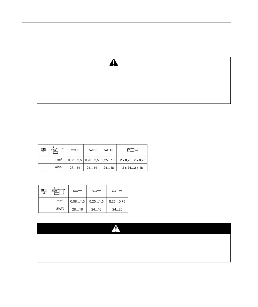
This table provides the wire sizes to use with the removable spring terminal blocks (TM5ACTB06,
TM5ACTB12, TM5ACTB12, TM5ACTB12PS, TM5ACTB32):
WARNING
1
.
18
This table provides the wire sizes to use with the TM5ACTB16 terminal blocks:
DANGER
FIRE HAZARD
Use only the correct wire sizes for the maximum current capacity of the I/O channels and power
supplies.
Failure to follow these instructions will result in death or serious injury.
EIO0000004159 09/2020
Page 19
The spring clamp connectors of the terminal block are designed for only one wire or one cable end.
Two wires to the same connector must be installed with a double wire cable end to help prevent
loosening.
LOOSE WIRING CAUSES ELECTRIC SHOCK
Do not insert more than one wire per connector of the spring terminal blocks unless using a
double wire cable end (ferrule).
Failure to follow these instructions will result in death or serious injury.
TM5 Terminal Block
Inserting an incorrect terminal block into the electronic module can cause unintended operation of
the application and/or damage the electronic module.
ELECTRIC SHOCK OR UNINTENDED EQUIPMENT OPERATION
Connect the terminal blocks to their designated location.
Failure to follow these instructions will result in death or serious injury.
Rules for Implementing
DANGER
DANGER
NOTE: To help prevent a terminal block from being inserted incorrectly, ensure that each terminal
block and electronic module is clearly and uniquely coded.
EIO0000004159 09/2020 19
Page 20

Rules for Implementing
TM5 Strain Relief Using Cable Tie
There are 2 methods to reduce the stress on cables:
The terminal blocks have slots to attach cable ties. A cable tie can be fed through this slot to
secure cables and wires to reduce stress between them and the terminal block connections.
After grounding the TM5 System by means of the grounding plate TM2XMTGB, wires can be
bundled and affixed to the grounding plate tabs using wire ties to reduce stress on the cables.
The following table provides the size of the cable tie and presents the two methods to reduce the
stress on the cables:
Cable Tie
Size
Thickness 1.2 mm (0.05 in.) maximum 1.2 mm (0.05 in.)
Width 4 mm (0.16 in.) maximum 2.5...3 mm (0.1...0.12 in.)
Mounting
illustration
Terminal Block TM2XMTGB Grounding Plate
WARNING
ACCIDENTAL DISCONNECTION FROM PROTECTIVE GROUND (PE)
Do not use the TM2XMTGB Grounding Plate to provide a protective ground (PE).
Use the TM2XMTGB Grounding Plate only to provide a functional ground (FE).
Failure to follow these instructions can result in death, serious injury, or equipment damage.
20
EIO0000004159 09/2020
Page 21

Protecting Outputs from Inductive Load Damage
Depending on the load, a protection circuit may be needed for the outputs on the controllers and
certain modules. Inductive loads using DC voltages may create voltage reflections resulting in
overshoot that will damage or shorten the life of output devices.
INDUCTIVE LOADS
Use an appropriate external protective circuit or device to reduce the risk of inductive direct
current load damage.
Failure to follow these instructions can result in death, serious injury, or equipment damage.
If your controller or module contains relay outputs, these types of outputs can support up to
240 Vac. Inductive damage to these types of outputs can result in welded contacts and loss of
control. Each inductive load must include a protection device such as a peak limiter, RC circuit or
flyback diode. Capacitive loads are not supported by these relays.
RELAY OUTPUTS WELDED CLOSED
Always protect relay outputs from inductive alternating current load damage using an
appropriate external protective circuit or device.
Do not connect relay outputs to capacitive loads.
Failure to follow these instructions can result in death, serious injury, or equipment damage.
Rules for Implementing
WARNING
WARNING
Protective circuit A: this protection circuit can be used for both AC and DC load power circuits.
C Value from 0.1 to 1 μF
R Resistor of approximately the same resistance value as the load
EIO0000004159 09/2020 21
Page 22
Rules for Implementing
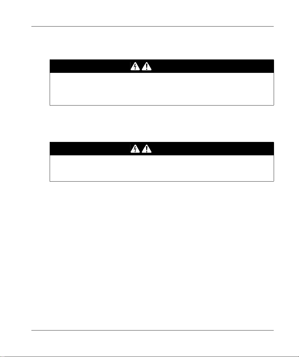
Protective circuit B: this protection circuit can be used for DC load power circuits.
Use a diode with the following ratings:
Reverse withstand voltage: power voltage of the load circuit x10.
Forward current: more than the load current.
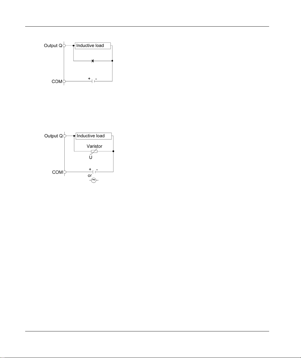
Protective circuit C: this protection circuit can be used for both AC and DC load power circuits.
22
In applications where the inductive load is switched on and off frequently and/or rapidly, ensure
that the continuous energy rating (J) of the varistor exceeds the peak load energy by 20 % or more.
EIO0000004159 09/2020
Page 23

Rules for Implementing
TM5 Environmental Characteristics
Enclosure Requirements
TM5 components are designed as Zone B, Class A industrial equipment according to IEC/CISPR
Publication 11. If they are used in environments other than those described in the standard, or in
environments that do not meet the specifications in this manual, your ability to meet
electromagnetic compatibility requirements in the presence of conducted and/or radiated
interference may be reduced.
The TM5 components meet European Community (CE) requirements for open equipment as
defined by EN61131-2. You must install them in an enclosure designed for the specific
environmental conditions and to minimize the possibility of unintended contact with hazardous
voltages. The enclosure should be constructed of metal to improve the electromagnetic immunity
of your TM5 System. The enclosure should, and in the case of UL compliance, must, have a keyed
locking mechanism to minimize unauthorized access.
Environmental Characteristics
This equipment meets UL and CSA standards and carry both certification marks. In addition, it is
certified as CE compliant. This equipment is intended for use in a Pollution Degree 2 industrial
environment.
The table below provides the general environmental characteristics:
Characteristic Minimum Specification Tested Range
Standard IEC61131-2 –
Agencies UL 508
CSA 22.2 No. 142-M1987
CSA 22.2 No. 213-M1987
Ambient operating temperature – Horizontal
–Vertical
Storage temperature – -25...70 °C (-13...158 °F)
Relative humidity – 5...95% (non-condensing)
Degree of pollution IEC60664 2
Degree of protection IEC61131-2 IP20
Corrosion immunity None –
Operating altitude – 0...2000 m (0...6.560 ft.)
Storage altitude – 0...3000 m (0...9.842 ft.)
NOTE: The tested ranges may indicate values beyond that of the IEC Standard. However, our internal standards
define what is necessary for industrial environments. In all cases, we uphold the minimum specification if indicated.
–
0...55 °C (32...131 °F)
installation
0...50 °C (32...122 °F)
installation
EIO0000004159 09/2020 23
Page 24
Rules for Implementing
Characteristic Minimum Specification Tested Range
Vibration resistance – Mounted on a
DIN rail
Mechanical shock resistance –
Connection
type
Connector insertion/removal cycles – 50
Removable spring
terminal block
––
147 m/s
2
(15 gn) for a duration of 11 ms
3.5 mm (0.138 in.) fixed
amplitude from 5...8.4 Hz
2
9.8 m/s
(1 gn) fixed
acceleration from
8.4...150 Hz
NOTE: The tested ranges may indicate values beyond that of the IEC Standard. However, our internal standards
define what is necessary for industrial environments. In all cases, we uphold the minimum specification if indicated.
NOTE: Replacement of the battery in the controllers other than with the type specified in this
documentation may present a risk of fire or explosion.
For more details on the procedures for replacing lithium batteries, refer to the RTC chapter
(see page 35)
.
WARNING
IMPROPER BATTERY CAN PROVOKE FIRE OR EXPLOSION
Replace battery only with identical type: Renata Type CR2477M.
Failure to follow these instructions can result in death, serious injury, or equipment damage.
24
EIO0000004159 09/2020
Page 25

Rules for Implementing
Electromagnetic Susceptibility
The following table provides the TM5 System electromagnetic susceptibility specifications:
Characteristic Minimum Specification Tested Range
Electrostatic discharge IEC/EN 61000-4-2 8 kV (air discharge), criteria B
Electromagnetic fields IEC/EN 61000-4-3 10 V/m (80 MHz...2 GHz), criteria A
Fast transients burst IEC/EN 61000-4-4 Power lines: 2 kV, criteria B
Surge immunity 24 Vdc circuit IEC/EN 61000-4-5 1 kV in common mode, criteria B
Surge immunity 230 Vac circuit IEC/EN 61000-4-5 2 kV in common mode, criteria B
Induced electromagnetic field IEC/EN 61000-4-6 10 V
Conducted emission EN 55011 (IEC/CISPR11) 150...500 kHz, quasi peak 79 dB (µV)
Radiated emission EN 55011 (IEC/CISPR11) 30...230 MHz, 10 m@40 dB (µV/m)
Criteria A Uninterrupted operation during test.
Criteria B Brief interruption during the test allowed.
(1) Applies for TM5SE1IC20005 and TM5SE1MISC20005.
4 kV (contact discharge), criteria B
10 V/m (80 MHz...2.7 GHz)
(1)
I/O: 1 kV, criteria B
Shielded cable: 1 kV, criteria B
Repetition rate: 5 and 100 KHz
0.5 kV in differential mode, criteria B
1 kV in differential mode, criteria B
(0.15...80 MHz), criteria A
eff
500 kHz...30 MHz, quasi peak 73 dB (µV)
230 MHz...1 GHz, 10 m@47 dB (µV/m)
NOTE: The tested ranges may indicate values beyond that of the IEC Standard. However, our internal standards
define what is necessary for industrial environments. In all cases, we uphold the minimum specification if indicated.
EIO0000004159 09/2020 25
Page 26

Rules for Implementing
26
EIO0000004159 09/2020
Page 27

Modicon M258
Modicon M258 Logic Controller Features
EIO0000004159 09/2020
Modicon M258 Logic Controller Features
Chapter 2
Modicon M258 Logic Controller Features
Introduction
This chapter describes the features of the Modicon M258 Logic Controller.
What Is in This Chapter?
This chapter contains the following topics:
About the Modicon M258 Logic Controller 28
Controller Description 30
Controller Common Characteristics 31
Real Time Clock (RTC) 34
Topic Page
EIO0000004159 09/2020 27
Page 28

Modicon M258 Logic Controller Features
About the Modicon M258 Logic Controller
Overview
The Schneider Electric Modicon M258 Logic Controller is a controller with a variety of features.
The Software configuration is described in the EcoStruxure Machine Expert Programming Guide.
Key Features
The EcoStruxure Machine Expert software supports the following IEC61131-3 programming
languages for use with these controllers:
IL: Instruction List
LD: Ladder Diagram
ST: Structured Text
FBD: Function Block Diagram
SFC: Sequential Function Chart
EcoStruxure Machine Expert software can also be used to program these controllers using CFC
(Continuous Function Chart) language.
The controllers support the following fieldbuses and network capabilities:
CANopen Master
Ethernet
Serial Line
The controllers support the following functions and I/O types:
Expert functions (counting, reflex outputs...)
Embedded I/Os
The controllers support up to 21 application program tasks with the following limits:
4 cyclic tasks: one is configured by default (MAST)
1 freewheeling task
8 software event driven tasks
8 hardware event driven tasks
28
EIO0000004159 09/2020
Page 29

Controller Range
TM258LD42DT
(see page 41)
TM258LD42DT4L
(see page 49)
TM258LF42DT
(see page 57)
TM258LF42DT4L
(see page 65)
TM258LF66DT4L
(see page 73)
TM258LF42DR
(see page 81)
TM258LD42DT
(see page 41)
TM258LD42DT4L
(see page 49)
TM258LF42DT
(see page 57)
TM258LF42DT4L
(see page 65)
TM258LF66DT4L
(see page 73)
TM258LF42DR
(see page 81)
Modicon M258 Logic Controller Features
PCI CAN USB A USB Pgr Ethernet Serial Line
00 1 1 1 1
20 1 1 1 1
01 1 1 1 1
21 1 1 1 1
21 1 1 1 1
21 1 1 1 1
Embedded Expert I/O Embedded Regular I/O
Fast Inputs Fast
Outputs
2x 5 2 2 1x 12 12 0
2x 5 2 2 1x 12 12 4
2x 5 2 2 1x 12 12 0
2x 5 2 2 1x 12 12 4
2x 5 2 2 2x 12 12 4
2x 5 2 2 2x 6 6 Relays 0
Regular
Inputs
Digital
Inputs
Digital
Outputs
Analog Inputs
EIO0000004159 09/2020 29
Page 30
Modicon M258 Logic Controller Features
CAN0
BATTERY (RTC)
MBS
Ethernet
Pgr Port
Host
MS
Eth NS
BATTERY
APP1
APP0
Eth LA
Eth ST
USB Host
MBS COM
CAN0 STS
RS485 / RS232
112
1
122
2
132
3
142
4
152
5
162
6
112
1
122
2
132
3
142
4
152
5
162
6
112
1
122
2
132
3
142
4
152
5
162
6
112
1
122
2
132
3
142
4
152
5
162
6
112
1
122
2
132
3
142
4
152
5
162
6
112
1
122
2
132
3
142
4
152
5
162
6
112
1
122
2
132
3
142
4
152
5
162
6
112
1
122
2
132
3
142
4
152
5
162
6
TM258
TM258LF42DT
EthMAC Address : xx-xx-xx-xx-xx-xx
PULL PULL
1
9 811
32 4 5114
76
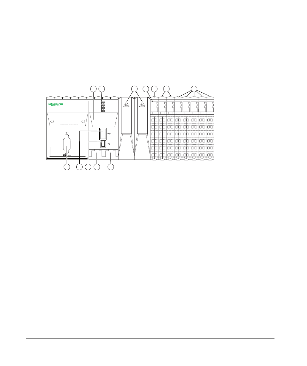
Controller Description
Overview
The Modicon M258 Logic Controller and its range are described below.
Physical Description
1 LED Status
2 PCI slots (depending on the controller reference)
3 Controller Power Distribution Module (CPDM)
4 Expert I/O (Embedded)
5 Regular I/O (Embedded)
6 USB A port (Host)
7 USB programming port (Pgr Port)
8 Ethernet port (Ethernet)
9 Serial Line port (MBS)
11 CANopen port (CAN0)
14 Real Time Clock battery (Battery (RTC))
30
EIO0000004159 09/2020
Page 31

Controller Common Characteristics
Overview
The common characteristics for all the Modicon M258 Logic Controllers are described below.
Programming
Use the EcoStruxure Machine Expert software to program the controller.
UNINTENDED EQUIPMENT OPERATION
Only use software approved by Schneider Electric for use with this equipment.
Update your application program every time you change the physical hardware configuration.
Failure to follow these instructions can result in death, serious injury, or equipment damage.
EcoStruxure Machine Expert is a professional, efficient and open OEM software solution that helps
you develop, configure and commission the entire machine in a single environment (including logic,
motor control, HMI and related network automation functions).
All information about EcoStruxure Machine Expert is included in the global EcoStruxure Machine
Expert software help system.
Modicon M258 Logic Controller Features
WARNING
Memory
The following table describes the different kinds of memory:
Memory type Size Used
RAM 64 Mbytes To execute the application.
Flash 128 Mbytes To save program and data in case of a power
outage.
Embedded Communication features
The four kinds of ports on the controller front panel are:
Ethernet port
CAN ports
USB ports
Serial Line Port
For more details, refer to the chapter Integrated Communication Ports
EIO0000004159 09/2020 31
(see page 91)
.
Page 32

Modicon M258 Logic Controller Features
PCI
The communication electronic module range includes:
RS232 connection electronic modules
RS485 connection electronic modules (for Serial Line and Profibus DP)
Controller Power Distribution Module (CPDM)
The controller power distribution module is divided into 3 power circuits:
24 Vdc Embedded expert modules power
24 Vdc Main power (for controller, fieldbus and TM5 power bus)
24 Vdc I/O power segment
There is no configuration necessary for this module.
Embedded Expert Input/Output
The controller base provides:
2 Embedded Expert I/O modules (DM72F0 and DM72F1) each with:
5 fast inputs
2 regular inputs
2 fast outputs
Embedded Regular Input/Output
The Embedded Regular I/O may include, depending on the controller range:
digital input electronic modules
digital output electronic modules
analog input electronic modules
relay output electronic modules
Every digital and analog electronic module channel has a status LED.
32
EIO0000004159 09/2020
Page 33

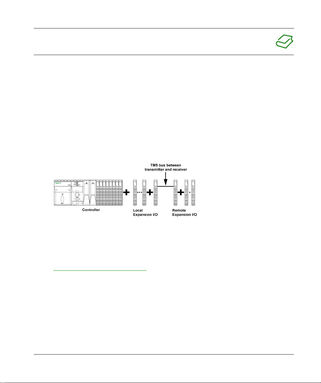
Expansion Modules
You can expand the number of I/Os for your controller by adding expansion I/O slices. The
following table lists the different types of electronic modules available to create expansion I/O
slices:
Reference Description
TM5C•• Compact I/O modules
TM5SD•• Digital modules
TM5SA•• Analog modules
TM5SPS•• Power distribution modules
TM5SE•• Specialized expansion modules
TM5SBE•• Transmitter and receiver modules
TM5SPD•• Common Distribution Module
TM5SD000 Dummy module
Modicon M258 Logic Controller Features
EIO0000004159 09/2020 33
Page 34

Modicon M258 Logic Controller Features
Real Time Clock (RTC)
Overview
These controllers include an RTC to provide system date and time information, and to support
related functions requiring a real-time clock. To continue to keep time when power is removed, a
non-rechargeable but replaceable battery is delivered with the controller. A battery LED indicates
if the battery charge is low or the battery absent.
The following table shows how RTC drift is managed:
RTC characteristics Description
RTC drift Less than 30 seconds per month without any user calibration at 25°C (77°F).
RTC drift with user logic
assistance
RTC Battery
The controller has one RTC battery.
In the event of a power outage, the backup battery will retain the time of the controller.
The table below shows the characteristics of the RTC battery:
Use In the event of a transient power outage, the battery will power the RTC.
Backup Time At least 1.5 years at 45°C max (113°F). At higher temperatures, the time is
reduced.
Battery Monitoring
Features
Replaceable Yes.
Controller RTC Battery
Type
Yes.
Type BBCV2, Renata Type CR2477M.
Less than or equal to 6 seconds per month with user calibration through
application software when the controller is in RUN mode.
34
EIO0000004159 09/2020
Page 35

Installing and Replacing the RTC battery
While lithium batteries are preferred due to their slow discharge and long life, they can present
hazards to personnel, equipment and the environment and must be handled properly.
EXPLOSION, FIRE, OR CHEMICAL BURNS
Replace with identical battery type.
Follow all the instructions of the battery manufacturer.
Remove all replaceable batteries before discarding unit.
Recycle or properly dispose of used batteries.
Protect battery from any potential short-circuit.
Do not recharge, disassemble, heat above 100 °C (212 °F), or incinerate.
Use your hands or insulated tools to remove or replace the battery.
Maintain proper polarity when inserting and connecting a new battery.
Failure to follow these instructions will result in death or serious injury.
To install or replace the RTC battery, follow these steps:
Step Action
1 Remove all power from your controller.
2 Slide out the battery holder of the controller:
Modicon M258 Logic Controller Features
DANGER
EIO0000004159 09/2020 35
Page 36

Modicon M258 Logic Controller Features
+
Step Action
3 Remove the battery from the battery holder:
2
4 Insert the new battery into the battery holder in accordance with the polarity
markings on the battery:
1
5 Replace the battery holder on the controller and verify that the latch clicks into place.
6 Re-apply power to the Modicon M258 Logic Controller.
NOTE: If you do nott apply power to the Modicon M258 Logic Controller
immediately, the external backup battery life might be significantly reduced.
7 Set the internal clock. For further details on the internal clock, please refer to RTC
Library.
36
EIO0000004159 09/2020
Page 37

Modicon M258 Logic Controller Features
NOTE: Replacement of the battery in the controllers other than with the type specified in this
documentation may present a risk of fire or explosion.
WARNING
IMPROPER BATTERY CAN PROVOKE FIRE OR EXPLOSION
Replace battery only with identical type: Renata Type CR2477M.
Failure to follow these instructions can result in death, serious injury, or equipment damage.
EIO0000004159 09/2020 37
Page 38

Modicon M258 Logic Controller Features
38
EIO0000004159 09/2020
Page 39

Modicon M258
Modicon M258 Logic Controller I nstallation
EIO0000004159 09/2020
Modicon M258 Logic Controller I nstallation
Chapter 3
Modicon M258 Logic Controller Installation
First Startup
Overview
This procedure helps you through the installation and startup of your controller.
Startup Procedure
Step Action Comment
1 Unpack your controller and check the contents of the package. Contents of package: Instruction
Sheet, Controller, Terminal blocks to
be mounted on the controller, RTC
battery in a separate bag
2 Choose an appropriate cabinet and DIN rail and install them. Refer to the Modicon Flexible TM5
3 Plug your controller on the DIN rail.
4 Connect your PCI expansion modules to the controller. Refer to the PCI Slots
5 Connect the expansion I/O slices (optional). Refer to the Modicon Flexible TM5
6 Connect your devices to the inputs and outputs. Refer to Modicon TM5 Analog I/O
7 Connect the external 24 Vdc power source(s) Controller Power
Distribution Module (CPDM) and any optional Power Distribution
Modules (PDM).
8 Connect your controller to the PC.
NOTE: EcoStruxure Machine Expert must be installed on the PC.
9 Verify all connections. —
10 Apply power. —
11 Login to your controller. —
12 Create an application. —
13 Load your application into the controller. —
System - System Planning and
Installation Guide.
(see page 109)
System - System Planning and
Installation Guide.
Modules Hardware Guide and Modicon
TM5 Digital I/O Modules Hardware
Guide.
Refer to CPDM Wiring Diagram
(see page 89)
.
Refer to Connecting the Controller to a
(see page 149)
PC
.
.
EIO0000004159 09/2020 39
Page 40

Modicon M258 Logic Controller Installation
Step Action Comment
14 Create your boot application. —
15 Run the application. —
40
EIO0000004159 09/2020
Page 41

Modicon M258
TM258LD42DT
EIO0000004159 09/2020
TM258LD42DT
Chapter 4
TM258LD42DT
Introduction
This chapter describes the TM258LD42DT controller.
What Is in This Chapter?
This chapter contains the following topics:
General Description 42
Characteristics of the Controller Power Distribution Module 46
Topic Page
EIO0000004159 09/2020 41
Page 42

TM258LD42DT
RS485 / RS232
General Description
Overview
The following illustration describes the different components of the TM258LD42DT:
TM258LF42DT
EthMAC Address : xx-xx-xx-xx-xx-xx
TM258
Eth LA
Eth ST
Eth NS
USB Host
MBS COM
CAN0 STS
Host
Pgr Port
MBS
16
BATTERY (RTC)
MS
BATTERY
APP0
APP1
Ethernet
31 41 42 51 52
112
112
1
122
122
2
132
132
3
142
142
4
152
152
5
162
162
6
235 4
112
1
122
2
132
3
142
4
152
5
162
6
112
1
122
2
132
3
142
4
152
5
162
6
112
1
122
2
132
3
142
4
152
5
162
6
1
2
3
4
5
6
N° Designation / Description Refer to
1 LED status Status LEDs
2 Ethernet port / Type RJ45 Ethernet Port
3 Serial line / Type RJ45 (RS232 or RS485) Serial Line Port
4 USB programming port / For terminal connection to a programming
USB Programming Port
PC (EcoStruxure Machine Expert)
5 USB host / For memory key management USB Host Port
6 Battery RTC Battery
31 Controller Power Distribution Module / For connecting external
power supplies
41 Embedded Expert I/O modules / 5 fast inputs, 2 regular inputs, 2
fast outputs
42
Controller Power Distribution Module
(see page 32)
Embedded Expert I/O
51 Embedded Regular Input module / 12 digital inputs Digital DI12DE
52 Embedded Regular Output module / 12 digital outputs Digital DO12TE
42
(see page 43)
(see page 92)
(see page 104)
(see page 100)
(see page 102)
(see page 34)
(see page 111)
(see page 130)
(see page 134)
EIO0000004159 09/2020
Page 43

Status LEDs
MS
Eth NS
BATTERY
APP1
APP0
Eth LA
Eth ST
USB Host
MBS COM
CAN0 STS
General Description
The following table describes the controller status LEDs:
Marking Description LED
MS Module status Green / Red See MS status LED below
BATTERY Battery status Red On when RTC battery needs to be
APP0 Application LEDs Green / Red Managed by user application
APP1
The following table describes the MS status LED:
TM258LD42DT
Color Description
replaced
Status LED Controller State Prg Port
Communication
Application
Execution
Flashing green / red BOOTING No No
Flashing red INVALID OS Restricted No
Single flash green EMPTY Yes No
Green ON RUNNING Yes Yes
3 flash green RUNNING with Breakpoint Yes Restricted
Flashing green STOPPED Restricted No
Single flash red HALT Yes No
Rapid flashing red REBOOT after a hardware error has
Yes No (Empty)
been detected
Red ON HALT after system error detected No No
OFF No power No No
Green / with single flash
red
RUNNING with external error
detected
Yes Yes
Or different Boot Project
Or no Boot Project
Flashing green / with
single flash red
EIO0000004159 09/2020 43
STOPPED with external error
detected
Restricted No
Page 44

TM258LD42DT
NOTE: For further details on controller states, refer to the Operating Mode discussion in the
Programming Guide for your particular controller.
For further details on the following LEDs:
Eth LA, Eth ST and Eth NS, please refer to Ethernet Port - Status LEDs
USB Host, please refer to USB Host Port - Status LED
MBS COM, please refer to Serial Line Port - Status LED
CAN0 STS, please refer to CAN Port - Status LED
Identifying the logic controller
The following illustration shows the LEDs on the front panel display:
The LEDs flash when the logic controller is being identified. For more information, refer to
EcoStruxure Machine Expert Programming Guide.
Controller States
The following table describes the controller states:
State Description
BOOTING The controller executes the boot firmware and its own internal self tests. It
INVALID_OS The Operating System is not valid. The controller can not execute an
EMPTY The user application is not valid or a hardware error has been detected. The
RUNNING The controller executes the application.
STOPPED The controller has a valid application that is stopped.
HALT The controller has detected an application or system error and has ceased
(see page 94)
(see page 103)
(see page 107)
(see page 99)
does not execute the application nor does it communicate. It then checks the
checksum of the firmware and user application.
application. Communications are restricted.
controller does not execute the application but it can communicate.
application execution.
.
.
.
.
44
NOTE: For further details on controller states, refer to the Operating Mode discussion in the
Programming Guide for your particular controller.
EIO0000004159 09/2020
Page 45

Dimensions
RS485 / RS232
85
3.35
The following illustration describes the external dimensions of the controller:
mm
in.
The following table describes the weight of the TM258LD42DT:
Weight
TM258LD42DT 500 g (17.6 oz)
TM258LF42DT
EthMAC Address : xx-xx-xx-xx-xx-xx
TM258
Eth LA
Eth ST
Eth NS
USB Host
MBS COM
CAN0 STS
Host
Pgr Port
MBS
175
6.89
BATTERY (RTC)
MS
BATTERY
APP0
APP1
Ethernet
112
122
132
142
152
162
112
1
122
2
132
3
142
4
152
5
162
6
112
1
122
2
132
3
142
4
152
5
162
6
TM258LD42DT
112
112
1
1
122
122
2
2
132
132
3
3
142
142
4
4
152
152
5
5
162
162
6
6
1
99
2
3.9
3
4
5
6
EIO0000004159 09/2020 45
Page 46

TM258LD42DT
POWER
Exp.
Ctrl
I/O
Characteristics of the Controller Power Distribution Module
The Controller Power Distribution Module (CPDM) has three 24 Vdc power connections:
Main power (Ctrl)
Expert I/O power (Exp.)
24 Vdc I/O Power Segment power (I/O)
The state of these three power connections is indicated by a set of LEDs on the CPDM:
46
The following table describes the CPDM LED display:
LEDs Color Status Description
Exp (Expert I/O power) Green On 24 Vdc applied
Ctrl (Main power) Green On 24 Vdc applied
I/O (24 Vdc I/O Power Segment
power)
Green On 24 Vdc applied
The Main power serves the TM5 power bus, the Serial Line port, the USB port, any PCI modules
that may be installed, and power for the controller electronics.
The Expert I/O power serves the Expert I/O module inputs and outputs, the power for the
embedded Encoder port, and power for the Expert I/O module electronics.
The 24 Vdc I/O power segment power serves the Regular I/O modules inputs and outputs, as well
as providing power to the first segment of the 24 Vdc I/O Power segment for any optional I/O slices
of the local configuration.
EIO0000004159 09/2020
Page 47

TM258LD42DT
CPDM Power Consumption Overview
The following table shows the power characteristics of the TM258LD42DT:
Rated voltage CPDM 24 Vdc
Voltage range CPDM 20.4...28.8 Vdc
Main power Minimum current (no external loads) 0.3 A
Maximum current including the following loads: 0.8 A
Embedded Expert
modules power
24 Vdc I/O power
segment
Current for TM5 bus power when adding
expansion modules
Current for serial line when connected
devices consume power
Current for USB Host when connected
devices consume power
Inrush current Time < 70 µs 100 A max.
70 ... 2000 µs 3 A max.
Internal protection No see note 1
Minimum current (no external loads) 0.04 A
Maximum current including the following loads: 0.9 A
Current for Expert Inputs 0...0.1 A
Current for Expert Outputs 0...0.8 A
Inrush current Time < 150 µs 50 A max.
Internal protection No see note 1
Maximum current (depending on the modules on the segment) 10 A max.
Inrush current
(depending on the
modules on the
segment)
Internal protection No see note 1
Time < 500 µs 25 A max.
0...0.1 A
0...0.05 A
0...0.1 A
1
Add external fuse as specified in the wiring diagrams.
Refer to the chapter
Example 1: Current Consumed by a Local Configuration
for further details on
power consumption.
EIO0000004159 09/2020 47
Page 48

TM258LD42DT
48
EIO0000004159 09/2020
Page 49

Modicon M258
TM258LD42DT4L
EIO0000004159 09/2020
TM258LD42DT4L
Chapter 5
TM258LD42DT4L
Introduction
This chapter describes the TM258LD42DT4L controller.
What Is in This Chapter?
This chapter contains the following topics:
General Description 50
Characteristics of the Controller Power Distribution Module 54
Topic Page
EIO0000004159 09/2020 49
Page 50

TM258LD42DT4L
BATTERY (RTC)
MBS
Ethernet
Pgr Port
Host
MS
Eth NS
BATTERY
APP1
APP0
Eth LA
Eth ST
USB Host
MBS COM
CAN0 STS
RS485 / RS232
112
1
122
2
132
3
142
4
152
5
162
6
1
121
122
2
132
3
142
4
152
5
162
6
1
121
122
2
132
3
142
4
152
5
162
6
1
121
122
2
132
3
142
4
152
5
162
6
1
121
122
2
132
3
142
4
152
5
162
6
1
121
122
2
132
3
142
4
152
5
162
6
TM258
TM258LF42DT
EthMAC Address : xx-xx-xx-xx-xx-xx
PULL
PULL
31 41 42 51 52 53
235 4
1
6
General Description
Overview
The following illustration shows the different components of the TM258LD42DT4L:
N° Designation Refer to
1 LED status Status LEDs
2 Ethernet port / Type RJ45 Ethernet Port
3 Serial line / Type RJ45 (RS232 or RS485) Serial Line Port
4 USB programming port / For terminal connection to a programming
USB Programming Port
PC (EcoStruxure Machine Expert)
5 USB host / For memory key management USB Host Port
6 Battery RTC Battery
31 Controller Power Distribution Module / For connecting external
power supplies
41 Embedded Expert I/O module / 5 fast inputs, 2 regular inputs, 2 f ast
42
51 Embedded Regular Input module / 12 digital inputs Digital DI12DE
outputs
52 Embedded Regular Output module / 12 digital outputs Digital DO12TE
53 Embedded Regular Input module / 4 analog inputs (12 bits) Analog AI4LE
50
Controller Power Distribution Module
(see page 32)
Embedded Expert I/O
(see page 51)
(see page 92)
(see page 104)
(see page 102)
(see page 34)
(see page 130)
(see page 139)
(see page 100)
(see page 111)
(see page 134)
EIO0000004159 09/2020
Page 51

Status LEDs
MS
Eth NS
BATTERY
APP1
APP0
Eth LA
Eth ST
USB Host
MBS COM
CAN0 STS
General Description
The following table describes the controller status LEDs:
Marking Description LED
MS Module status Green / Red See MS status LED below
BATTERY Battery status Red On when RTC battery needs to be
APP0 Application LEDs Green / Red Managed by user application
APP1
The following table describes the MS status LED:
TM258LD42DT4L
Color Description
replaced
Status LED Controller State Prg Port
Communication
Application
Execution
Flashing green / red BOOTING No No
Flashing red INVALID OS Restricted No
Single flash green EMPTY Yes No
Green ON RUNNING Yes Yes
3 flash green RUNNING with Breakpoint Yes Restricted
Flashing green STOPPED Restricted No
Single flash red HALT Yes No
Rapid flashing red REBOOT after a hardware error has
Yes No (Empty)
been detected
Red ON HALT after system error detected No No
OFF No power No No
Green / with single flash
red
RUNNING with external error detected
Or different Boot Project
Yes Yes
Or no Boot Project
Flashing green / with
STOPPED with external error detected Restricted No
single flash red
EIO0000004159 09/2020 51
Page 52

TM258LD42DT4L
NOTE: For further details on controller states, refer to the Operating Mode discussion in the
Programming Guide for your particular controller.
For further details on the following LEDs:
Eth LA, Eth ST and Eth NS, please refer to Ethernet Port - Status LEDs
USB Host, please refer to USB Host Port - Status LED
MBS COM, please refer to Serial Line Port - Status LED
CAN0 STS, please refer to CAN Port - Status LED
Identifying the logic controller
The following illustration shows the LEDs on the front panel display:
The LEDs flash when the logic controller is being identified. For more information, refer to
EcoStruxure Machine Expert Programming Guide.
Controller States
The following table describes the controller states:
State Description
BOOTING The controller executes the boot firmware and its own internal self tests. It
INVALID_OS The Operating System is not valid. The controller can not execute an
EMPTY The user application is not valid or a hardware error has been detected. The
RUNNING The controller executes the application.
STOPPED The controller has a valid application that is stopped.
HALT The controller has detected an application or system error and has ceased
(see page 94)
(see page 103)
(see page 107)
(see page 99)
does not execute the application nor does it communicate. It then checks the
checksum of the firmware and user application.
application. Communications are restricted.
controller does not execute the application but it can communicate.
application execution.
.
.
.
.
52
NOTE: For further details on controller states, refer to the Operating Mode discussion in the
Programming Guide for your particular controller.
EIO0000004159 09/2020
Page 53

Dimensions
85
3.35
The following illustration shows the external dimensions of the controller:
mm
in.
The following table describes the weight of the TM258LD42DT4L:
Weight
TM258LD42DT4L 770 g (24.7 oz)
TM258LF42DT
EthMAC Address : xx-xx-xx-xx-xx-xx
TM258
Eth LA
Eth ST
Eth NS
USB Host
MBS COM
CAN0 STS
Host
Pgr Port
MBS
RS485 / RS232
BATTERY (RTC)
MS
BATTERY
APP0
APP1
Ethernet
237,5
9.36
PULL PULL
112
122
132
142
152
162
112
1
122
2
132
3
142
4
152
5
162
6
TM258LD42DT4L
112
112
112
1
1
1
122
122
122
2
2
2
132
132
132
3
3
3
142
142
142
4
4
4
152
152
152
5
5
5
162
162
162
6
6
6
112
1
122
2
132
3
142
4
152
5
162
6
1
99
2
3.9
3
4
5
6
EIO0000004159 09/2020 53
Page 54

TM258LD42DT4L
POWER
Exp.
Ctrl
I/O
Characteristics of the Controller Power Distribution Module
The Controller Power Distribution Module (CPDM) has three 24 Vdc power connections:
Main power (Ctrl)
Expert I/O power (Exp.)
24 Vdc I/O Power Segment power (I/O)
The state of these three power connections is indicated by a set of LEDs on the CPDM:
54
The following table describes the CPDM LED display:
LEDs Color Status Description
Exp (Expert I/O power) Green On 24 Vdc applied
Ctrl(Main power) Green On 24 Vdc applied
I/O(24 Vdc I/O Power Segment
power)
Green On 24 Vdc applied
The Main power serves the TM5 power bus, the Serial Line port, the USB port, any PCI modules
that may be installed, and power for the controller electronics.
The Expert I/O power serves the Expert I/O module inputs and outputs, the power for the
embedded Encoder port, and power for the Expert I/O module electronics.
The 24 Vdc I/O power segment power serves the Regular I/O modules inputs and outputs, as well
as providing power to the first segment of the 24 Vdc I/O Power segment for any optional I/O slices
of the local configuration.
EIO0000004159 09/2020
Page 55

TM258LD42DT4L
CPDM Power Consumption Overview
The following table shows the power characteristics of the TM258LD42DT4L:
Rated voltage CPDM 24 Vdc
Voltage range CPDM 20.4...28.8 Vdc
Main power Minimum current (no external loads) 0.3 A
Maximum current including the following loads: 1.2 A
Embedded Expert
modules power
24 Vdc I/O power
segment
Current for TM5 bus power when adding
expansion modules
Current for serial line when connected
devices consume power
Current for USB Host when connected
devices consume power
Current for optional PCI modules when
connected devices consume power
Inrush current Time < 70 µs 100 A max.
70...2000 µs 3 A max.
Internal protection No see note 1
Minimum current (no external loads) 0.04 A
Maximum current including the following loads: 0.9 A
Current for Expert Inputs 0...0.1 A
Current for Expert Outputs 0...0.8 A
Inrush current Time < 150 µs 50 A max.
Internal protection No see note 1
Maximum current (depending on the modules on the segment) 10 A max.
Inrush current
(depending on the
modules on the
segment)
Internal protection No see note 1
Time < 500 µs 25 A max.
0...0.1 A
0...0.05 A
0...0.1 A
Refer to your specific PCI
module
1
Add external fuse as specified in the wiring diagrams.
Refer to the chapter
Example 1: Current Consumed by a Local Configuration
for further details on
power consumption.
EIO0000004159 09/2020 55
Page 56

TM258LD42DT4L
56
EIO0000004159 09/2020
Page 57

Modicon M258
TM258LF42DT
EIO0000004159 09/2020
TM258LF42DT
Chapter 6
TM258LF42DT
Introduction
This chapter describes the TM258LF42DT controller.
What Is in This Chapter?
This chapter contains the following topics:
General Description 58
Characteristics of the Controller Power Distribution Module 62
Topic Page
EIO0000004159 09/2020 57
Page 58

TM258LF42DT
CAN0
BATTERY (RTC)
MBS
Ethernet
Pgr Port
Host
MS
Eth NS
BATTERY
APP1
APP0
Eth LA
Eth ST
USB Host
MBS COM
CAN0 STS
RS485 / RS232
112
1
122
2
132
3
142
4
152
5
162
6
112
1
122
2
132
3
142
4
152
5
162
6
112
1
122
2
132
3
142
4
152
5
162
6
112
1
122
2
132
3
142
4
152
5
162
6
112
1
122
2
132
3
142
4
152
5
162
6
TM258
TM258LF42DT
EthMAC Address : xx-xx-xx-xx-xx-xx
31 41 42 51 52
237 5 4
16
General Description
Overview
The following illustration shows the different components of the TM258LF42DT:
N° Designation / Description Refer to
1 LED status Status LEDs
2 Ethernet port / Type RJ45 Ethernet Port
3 Serial line / Type RJ45 (RS232 or RS485) Serial Line Port
4 USB programming port /For terminal connection to a programming PC
(EcoStruxure Machine Expert)
5 USB host / For memory key management USB Host Port
6 Battery RTC Battery
7 CAN 0 port / Male D-Sub 9 CANopen Master CAN Port
31 Controller Power Distribution Module / For connecting external power
supplies
41 Embedded Expert I/O modules / 5 fast inputs, 2 regular inputs, 2 fast
outputs
42
51 Embedded Regular Input module / 12 digital inputs Digital DI12DE
52 Embedded Regular Output module / 12 digital outputs Digital DO12TE
58
USB Programming Port
(see page 100)
Controller Power Distribution
Module
Embedded Expert I/O
(see page 111)
(see page 59)
(see page 92)
(see page 104)
(see page 102)
(see page 34)
(see page 96)
(see page 32)
(see page 130)
(see page 134)
EIO0000004159 09/2020
Page 59

Status LEDs
MS
Eth NS
BATTERY
APP1
APP0
Eth LA
Eth ST
USB Host
MBS COM
CAN0 STS
General Description
The following table describes the controller status LEDs:
Marking Description LED
MS Module status Green / Red See MS status LED below
BATTERY Battery status Red On when RTC battery needs to be
APP0 Application LEDs Green / Red Managed by user application
APP1
The following table describes the MS status LED:
TM258LF42DT
Color Description
replaced
Status LED Controller State Prg Port
Communication
Application
Execution
Flashing green / red BOOTING No No
Flashing red INVALID OS Restricted No
Single flash green EMPTY Yes No
Green ON RUNNING Yes Yes
3 flash green RUNNING with Breakpoint Yes Restricted
Flashing green STOPPED Restricted No
Single flash red HALT Yes No
Rapid flashing red REBOOT after a hardware error has
Yes No (Empty)
been detected
Red ON HALT after system error detected No No
OFF No power No No
Green / with single flash
red
RUNNING with external error
detected
Yes Yes
Or different Boot Project
Or no Boot Project
Flashing green / with
single flash red
EIO0000004159 09/2020 59
STOPPED with external error
detected
Restricted No
Page 60

TM258LF42DT
NOTE: For further details on controller states, refer to the Operating Mode discussion in the
Programming Guide for your particular controller.
For further details on the following LEDs:
Eth LA, Eth ST and Eth NS, please refer to Ethernet Port - Status LEDs
USB Host, please refer to USB Host Port - Status LED
MBS COM, please refer to Serial Line Port - Status LED
CAN0 STS, please refer to CAN Port - Status LED
Identifying the logic controller
The following illustration shows the LEDs on the front panel display:
The LEDs flash when the logic controller is being identified. For more information, refer to
EcoStruxure Machine Expert Programming Guide.
Controller States
The following table describes the controller states:
State Description
BOOTING The controller executes the boot firmware and its own internal self tests. It
INVALID_OS The Operating System is not valid. The controller can not execute an
EMPTY The user application is not valid or a hardware error has been detected. The
RUNNING The controller executes the application.
STOPPED The controller has a valid application that is stopped.
HALT The controller has detected an application or system error and has ceased
(see page 94)
(see page 103)
(see page 107)
(see page 99)
does not execute the application nor does it communicate. It then checks the
checksum of the firmware and user application.
application. Communications are restricted.
controller does not execute the application but it can communicate.
application execution.
.
.
.
.
60
NOTE: For further details on controller states, refer to the Operating Mode discussion in the
Programming Guide for your particular controller.
EIO0000004159 09/2020
Page 61

Dimensions
85
3.35
The following illustration shows the external dimensions of the controller:
mm
in.
The following table describes the weight of the TM258LF42DT:
Weight
TM258LF42DT 550 g (19.4 oz)
TM258LF42DT
EthMAC Address : xx-xx-xx-xx-xx-xx
CAN0
TM258
6.89
Eth LA
Eth ST
Eth NS
USB Host
MBS COM
CAN0 STS
BATTERY (RTC)
Host
Pgr Port
MBS
RS485 / RS232
175
MS
BATTERY
APP0
APP1
Ethernet
112
122
132
142
152
162
112
1
122
2
132
3
142
4
152
5
162
6
112
1
122
2
132
3
142
4
152
5
162
6
TM258LF42DT
112
112
1
1
122
122
2
2
132
132
3
3
142
142
4
4
152
152
5
5
162
162
6
6
1
99
2
3.9
3
4
5
6
EIO0000004159 09/2020 61
Page 62

TM258LF42DT
POWER
Exp.
Ctrl
I/O
Characteristics of the Controller Power Distribution Module
The Controller Power Distribution Module (CPDM) has three 24 Vdc power connections:
Main power (Ctrl)
Expert I/O power (Exp.)
24 Vdc I/O Power Segment power (I/O)
The state of these three power connections is indicated by a set of LEDs on the CPDM:
62
The following table describes the CPDM LED display:
LEDs Color Status Description
Exp (Expert I/O power) Green On 24 Vdc applied
Ctrl (Main power) Green On 24 Vdc applied
I/O (24 Vdc I/O Power Segment
power)
Green On 24 Vdc applied
The Main power serves the TM5 power bus, the Serial Line port, the USB port, any PCI modules
that may be installed, and power for the controller electronics.
The Expert I/O power serves the Expert I/O module inputs and outputs, the power for the
embedded Encoder port, and power for the Expert I/O module electronics.
The 24 Vdc I/O power segment power serves the Regular I/O modules inputs and outputs, as well
as providing power to the first segment of the 24 Vdc I/O Power segment for any optional I/O slices
of the local configuration.
EIO0000004159 09/2020
Page 63

TM258LF42DT
CPDM Power Consumption Overview
The following table shows the power characteristics of the TM258LF42DT:
Rated voltage CPDM 24 Vdc
Voltage range CPDM 20.4...28.8 Vdc
Main power Minimum current (no external loads) 0.3 A
Maximum current including the following loads: 0.8 A
Embedded Expert
modules power
24 Vdc I/O power
segment
Current for TM5 bus power when adding
expansion modules
Current for serial line when connected
devices consume power
Current for USB Host when connected
devices consume power
Inrush current Time < 70 µs 100 A max.
70...2000 µs 3 A max.
Internal protection No see note 1
Minimum current (no external loads) 0.04 A
Maximum current including the following loads: 0.9 A
Current for Expert Inputs 0...0.1 A
Current for Expert Outputs 0...0.8 A
Inrush current Time < 150 µs 50 A max.
Internal protection No see note 1
Maximum current (depending on the modules on the segment) 10 A max.
Inrush current
(depending on the
modules on the
segment)
Internal protection No see note 1
Time < 500 µs 25 A max.
0...0.1 A
0...0.05 A
0...0.1 A
1
Add external fuse as specified in the wiring diagrams.
Refer to the chapter
Example 1: Current Consumed by a Local Configuration
for further details on
power consumption.
EIO0000004159 09/2020 63
Page 64

TM258LF42DT
64
EIO0000004159 09/2020
Page 65

Modicon M258
TM258LF42DT4L
EIO0000004159 09/2020
TM258LF42DT4L
Chapter 7
TM258LF42DT4L
Introduction
This chapter describes the TM258LF42DT4L controller.
What Is in This Chapter?
This chapter contains the following topics:
General Description 66
Characteristics of the Controller Power Distribution Module 70
Topic Page
EIO0000004159 09/2020 65
Page 66

TM258LF42DT4L
CAN0
BATTERY (RTC)
MBS
Ethernet
Pgr Port
Host
MS
Eth NS
BATTERY
APP1
APP0
Eth LA
Eth ST
USB Host
MBS COM
CAN0 STS
RS485 / RS232
112
1
122
2
132
3
142
4
152
5
162
6
112
1
122
2
132
3
142
4
152
5
162
6
112
1
122
2
132
3
142
4
152
5
162
6
112
1
122
2
132
3
142
4
152
5
162
6
112
1
122
2
132
3
142
4
152
5
162
6
112
1
122
2
132
3
142
4
152
5
162
6
TM258
TM258LF42DT
EthMAC Address : xx-xx-xx-xx-xx-xx
PULLPULL
31 41 42 51 52 53
237 5 4
16
General Description
Overview
The following illustration shows the different components of the TM258LF42DT4L:
N° Designation / Description Refer to
1 LED status Status LEDs
2 Ethernet port / Type RJ45 Ethernet Port
3 Serial line / Type RJ45 (RS232 or RS485) Serial Line Port
4 USB programming port /For terminal connection to a
USB Programming Port
programming PC (EcoStruxure Machine Expert)
5 USB host / For memory key management USB Host Port
6 Battery RTC Battery
7 CAN 0 Port / Male Sub-D 9 CANopen Master CAN Port
31 Controller Power Distribution Module / For connecting external
power supplies
41 Embedded Expert I/O modules / 5 fast inputs, 2 regular inputs,
2 fast outputs
42
51 Embedded Regular Input module / 12 digital inputs Digital DI12DE
52 Embedded Regular Output module / 12 digital outputs Digital DO12TE
53 Embedded Regular Input module / 4 analog inputs (12-bits) Analog AI4LE
66
Controller Power Distribution Module
(see page 32)
Embedded Expert I/O
(see page 67)
(see page 92)
(see page 104)
(see page 102)
(see page 34)
(see page 96)
(see page 130)
(see page 134)
(see page 139)
(see page 100)
(see page 111)
EIO0000004159 09/2020
Page 67

Status LEDs
MS
Eth NS
BATTERY
APP1
APP0
Eth LA
Eth ST
USB Host
MBS COM
CAN0 STS
General Description
The following table describes the controller status LEDs:
Marking Description LED
MS Module status Green / Red See MS status LED below
BATTERY Battery status Red On when RTC battery needs to be
APP0 Application LEDs Green / Red Managed by user application
APP1
The following table describes the MS status LED:
TM258LF42DT4L
Color Description
replaced
Status LED Controller State Prg Port
Communication
Application
Execution
Flashing green / red BOOTING No No
Flashing red INVALID OS Restricted No
Single flash green EMPTY Yes No
Green ON RUNNING Yes Yes
3 flash green RUNNING with Breakpoint Yes Restricted
Flashing green STOPPED Restricted No
Single flash red HALT Yes No
Rapid flashing red REBOOT after a hardware error
Yes No (Empty)
has been detected
Red ON HALT after system error detected No No
OFF No power No No
Green / with single flash
red
RUNNING with external error
detected
Yes Yes
Or different Boot Project
Or no Boot Project
Flashing green / with
single flash red
EIO0000004159 09/2020 67
STOPPED with external error
detected
Restricted No
Page 68

TM258LF42DT4L
NOTE: For further details on controller states, refer to the Operating Mode discussion in the
Programming Guide for your particular controller.
For further details on the following LEDs:
Eth LA, Eth ST and Eth NS, please refer to Ethernet Port - Status LEDs
USB Host, please refer to USB Host Port - Status LED
MBS COM, please refer to Serial Line Port - Status LED
CAN0 STS, please refer to CAN Port - Status LED
Identifying the logic controller
The following illustration shows the LEDs on the front panel display:
The LEDs flash when the logic controller is being identified. For more information, refer to
EcoStruxure Machine Expert Programming Guide.
Controller States
The following table describes the controller states:
State Description
BOOTING The controller executes the boot firmware and its own internal self tests. It
INVALID_OS The Operating System is not valid. The controller can not execute an
EMPTY The user application is not valid or a hardware error has been detected. The
RUNNING The controller executes the application.
STOPPED The controller has a valid application that is stopped.
HALT The controller has detected an application or system error and has ceased
(see page 94)
(see page 103)
(see page 107)
(see page 99)
does not execute the application nor does it communicate. It then checks the
checksum of the firmware and user application.
application. Communications are restricted.
controller does not execute the application but it can communicate.
application execution.
.
.
.
.
68
NOTE: For further details on controller states, refer to the Operating Mode discussion in the
Programming Guide for your particular controller.
EIO0000004159 09/2020
Page 69

Dimensions
85
3.35
The following illustration shows the external dimensions of the controller:
mm
The following table describes the weight of the TM258LF42DT4L:
Weight
TM258LF42DT4L 770 g (24.7 oz)
TM258LF42DT4L
BATTERY (RTC)
MS
BATTERY
APP0
APP1
Ethernet
237,5
9.36
PULL PULL
112
122
132
142
152
162
112
1
122
2
132
3
142
4
152
5
162
6
112
1
122
2
132
3
142
4
152
5
162
6
112
1
122
2
132
3
142
4
152
5
162
6
1
2
3
4
5
6
112
122
132
142
152
162
112
1
122
2
132
3
142
4
152
5
162
6
1
99
2
3.9
3
4
5
6
in.
Eth LA
Eth ST
Eth NS
USB Host
MBS COM
CAN0 STS
TM258
TM258LF42DT
EthMAC Address : xx-xx-xx-xx-xx-xx
CAN0
Host
Pgr Port
MBS
RS485 / RS232
EIO0000004159 09/2020 69
Page 70

TM258LF42DT4L
POWER
Exp.
Ctrl
I/O
Characteristics of the Controller Power Distribution Module
The Controller Power Distribution Module (CPDM) has three 24 Vdc power connections:
Main power (Ctrl)
Expert I/O power (Exp.)
24 Vdc I/O Power Segment power (I/O)
The state of these three power connections is indicated by a set of LEDs on the CPDM:
70
The following table describes the CPDM LED display:
LEDs Color Status Description
Exp (Expert I/O power) Green On 24 Vdc applied
Ctrl (Main power) Green On 24 Vdc applied
I/O (24 Vdc I/O Power Segment
power)
Green On 24 Vdc applied
The Main power serves the TM5 power bus, the Serial Line port, the USB port, any PCI modules
that may be installed, and power for the controller electronics.
The Expert I/O power serves the Expert I/O module inputs and outputs, the power for the
embedded Encoder port, and power for the Expert I/O module electronics.
The 24 Vdc I/O power segment power serves the Regular I/O modules inputs and outputs, as well
as providing power to the first segment of the 24 Vdc I/O Power segment for any optional I/O slices
of the local configuration.
EIO0000004159 09/2020
Page 71

TM258LF42DT4L
CPDM Power Consumption Overview
The following table shows the power characteristics of the TM258LF42DT4L:
Rated voltage CPDM 24 Vdc
Voltage range CPDM 20.4...28.8 Vdc
Main power Minimum current (no external loads) 0.3 A
Maximum current including the following loads: 1.2 A
Embedded Expert
modules power
24 Vdc I/O power
segment
Current for TM5 bus power when adding
expansion modules
Current for serial line when connected
devices consume power
Current for USB Host when connected
devices consume power
Current for optional PCI modules when
connected devices consume power
Inrush current Time < 70 µs 100 A max.
70...2000 µs 3 A max.
Internal protection No see note 1
Minimum current (no external loads) 0.04 A
Maximum current including the following loads: 0.9 A
Current for Expert Inputs 0...0.1 A
Current for Expert Outputs 0...0.8 A
Inrush current Time < 150 µs 50 A max.
Internal protection No see note 1
Maximum current (depending on the modules on the segment) 10 A max.
Inrush current
(depending on the
modules on the
segment)
Internal protection No see note 1
Time < 500 µs 25 A max.
0...0.1 A
0...0.05 A
0...0.1 A
Refer to your specific PCI
module
1
Add external fuse as specified in the wiring diagrams.
Refer to the chapter
Example 1: Current Consumed by a Local Configuration
for further details on
power consumption.
EIO0000004159 09/2020 71
Page 72

TM258LF42DT4L
72
EIO0000004159 09/2020
Page 73

Modicon M258
TM258LF66DT4L
EIO0000004159 09/2020
TM258LF66DT4L
Chapter 8
TM258LF66DT4L
Introduction
This chapter describes the TM258LF66DT4L controller.
What Is in This Chapter?
This chapter contains the following topics:
General Description 74
Characteristics of the Controller Power Distribution Module 78
Topic Page
EIO0000004159 09/2020 73
Page 74

TM258LF66DT4L
General Description
Overview
The following illustration shows the different components of the TM258LF66DT4L:
16
31 41 42 51 52 53 54 55
PULL
112
122
132
142
152
162
112
1
122
2
132
3
142
4
152
5
162
6
112
1
122
2
132
3
142
4
152
5
162
6
112
1
122
2
132
3
142
4
152
5
162
6
112
1
122
2
132
3
142
4
152
5
162
6
TM258LF42DT
EthMAC Address : xx-xx-xx-xx-xx-xx
CAN0
TM258
Eth LA
Eth ST
Eth NS
USB Host
MBS COM
CAN0 STS
BATTERY (RTC)
Host
Pgr Port
MBS
RS485 / RS232
MS
BATTERY
APP0
APP1
PULL
Ethernet
237 5 4
N° Designation / Description Refer to
1 LED status Status LEDs
2 Ethernet port / Type RJ45 Ethernet Port
(see page 75)
(see page 92)
3 Serial line / Type RJ45 (RS232 or RS485) Serial Line Port
4 USB programming port / For terminal connection to a programming
USB Programming Port
PC (EcoStruxure Machine Expert)
5 USB host / For memory key management USB Host Port
6 Battery RTC Battery
7 CAN 0 Port / Male Sub-D 9 CANopen Master CAN Port
31 Controller Power distribution Module / For connecting external
power supplies
41 Embedded Expert I/O modules / 5 fast inputs, 2 regular inputs,
2 fast outputs
42
Controller Power Distribution Module
(see page 32)
Embedded Expert I/O
(see page 34)
(see page 96)
51 Embedded Regular Input modules / 12 digital inputs Digital DI12DE
52
53 Embedded Regular Output modules / 12 digital outputs Digital DO12TE
54
55 Embedded Regular Input module / 4 analog inputs (12-bits) Analog AI4LE
112
112
1
122
2
132
3
142
4
152
5
162
6
112
1
122
2
132
3
142
4
152
5
162
6
1
122
2
132
3
142
4
152
5
162
6
(see page 104)
(see page 100)
(see page 102)
(see page 111)
(see page 130)
(see page 134)
(see page 139)
1
2
3
4
5
6
74
EIO0000004159 09/2020
Page 75

Status LEDs
MS
Eth NS
BATTERY
APP1
APP0
Eth LA
Eth ST
USB Host
MBS COM
CAN0 STS
General Description
The following table describes the controller status LEDs:
Marking Description LED
MS Module status Green / Red See MS status LED below
BATTERY Battery status Red On when RTC battery needs to be
APP0 Application LEDs Green / Red Managed by user application
APP1
The following table describes the MS status LED:
TM258LF66DT4L
Color Description
replaced
Status LED Controller State Prg Port
Communication
Application
Execution
Flashing green / red BOOTING No No
Flashing red INVALID OS Restricted No
Single flash green EMPTY Yes No
Green ON RUNNING Yes Yes
3 flash green RUNNING with Breakpoint Yes Restricted
Flashing green STOPPED Restricted No
Single flash red HALT Yes No
Rapid flashing red REBOOT after a hardware error has
Yes No (Empty)
been detected
Red ON HALT after system error detected No No
OFF No power No No
Green / with single flash
red
RUNNING with external error
detected
Yes Yes
Or different Boot Project
Or no Boot Project
Flashing green / with
single flash red
EIO0000004159 09/2020 75
STOPPED with external error
detected
Restricted No
Page 76

TM258LF66DT4L
NOTE: For further details on controller states, refer to the Operating Mode discussion in the
Programming Guide for your particular controller.
For further details on the following LEDs:
Eth LA, Eth ST and Eth NS, please refer to Ethernet Port - Status LEDs
USB Host, please refer to USB Host Port - Status LED
MBS COM, please refer to Serial Line Port - Status LED
CAN0 STS, please refer to CAN Port - Status LED
Identifying the logic controller
The following illustration shows the LEDs on the front panel display:
The LEDs flash when the logic controller is being identified. For more information, refer to
EcoStruxure Machine Expert Programming Guide.
Controller States
The following table describes the controller states:
State Description
BOOTING The controller executes the boot firmware and its own internal self tests. It
INVALID_OS The Operating System is not valid. The controller can not execute an
EMPTY The user application is not valid or a hardware error has been detected. The
RUNNING The controller executes the application.
STOPPED The controller has a valid application that is stopped.
HALT The controller has detected an application or system error and has ceased
(see page 94)
(see page 103)
(see page 107)
(see page 99)
does not execute the application nor does it communicate. It then checks the
checksum of the firmware and user application.
application. Communications are restricted.
controller does not execute the application but it can communicate.
application execution.
.
.
.
.
76
NOTE: For further details on controller states, refer to the Operating Mode discussion in the
Programming Guide for your particular controller.
EIO0000004159 09/2020
Page 77

Dimensions
85
3.35
The following illustration shows the external dimensions of the controller:
mm
in.
The following table describes the weight of the TM258LF66DT4L:
Weight
TM258LF66DT4L 800 g (28.2 oz)
TM258LF42DT
EthMAC Address : xx-xx-xx-xx-xx-xx
CAN0
TM258
Eth LA
Eth ST
Eth NS
USB Host
MBS COM
CAN0 STS
Host
Pgr Port
MBS
RS485 / RS232
BATTERY (RTC)
MS
BATTERY
APP0
APP1
Ethernet
262,5
10.34
PULL PULL
112
122
132
142
152
162
1
2
3
4
5
6
112
122
132
142
152
162
1
2
3
4
5
6
112
122
132
142
152
162
1
2
3
4
5
6
112
122
132
142
152
162
1
2
3
4
5
6
112
122
132
142
152
162
112
1
122
2
132
3
142
4
152
5
162
6
TM258LF66DT4L
112
112
1
1
1
122
122
2
3
4
5
6
132
142
152
162
99
2
3.9
3
4
5
6
2
132
3
142
4
152
5
162
6
EIO0000004159 09/2020 77
Page 78

TM258LF66DT4L
POWER
Exp.
Ctrl
I/O
Characteristics of the Controller Power Distribution Module
The Controller Power Distribution Module (CPDM) has three 24 Vdc power connections:
Main power (Ctrl)
Expert I/O power (Exp.)
24 Vdc I/O Power Segment power (I/O)
The state of these three power connections is indicated by a set of LEDs on the CPDM:
78
The following table describes the CPDM LED display:
LEDs Color Status Description
Exp (Expert I/O power) Green On 24 Vdc applied
Ctrl (Main power) Green On 24 Vdc applied
I/O (24 Vdc I/O Power Segment
power)
Green On 24 Vdc applied
The Main power serves the TM5 power bus, the Serial Line port, the USB port, any PCI modules
that may be installed, and power for the controller electronics.
The Expert I/O power serves the Expert I/O module inputs and outputs, the power for the
embedded Encoder port, and power for the Expert I/O module electronics.
The 24 Vdc I/O power segment power serves the Regular I/O modules inputs and outputs, as well
as providing power to the first segment of the 24 Vdc I/O Power segment for any optional I/O slices
of the local configuration.
EIO0000004159 09/2020
Page 79

TM258LF66DT4L
CPDM Power Consumption Overview
The following table shows the power characteristics of the TM258LF66DT4L:
Rated voltage CPDM 24 Vdc
Voltage range CPDM 20.4...28.8 Vdc
Main power Minimum current (no external loads) 0.3 A
Maximum current including the following loads: 1.2 A
Embedded Expert
modules power
24 Vdc I/O power
segment
Current for TM5 bus power when adding
expansion modules
Current for serial line when connected
devices consume power
Current for USB Host when connected
devices consume power
Current for optional PCI modules when
connected devices consume power
Inrush current Time < 70 µs 100 A max.
70...2000 µs 3 A max.
Internal protection No see note 1
Minimum current (no external loads) 0.04 A
Maximum current including the following loads: 0.9 A
Current for Expert Inputs 0...0.1 A
Current for Expert Outputs 0...0.8 A
Inrush current Time < 150 µs 50 A max.
Internal protection No see note 1
Maximum current (depending on the modules on the segment) 10 A max.
Inrush current
(depending on the
modules on the
segment)
Internal protection No see note 1
Time < 500 µs 25 A max.
0...0.1 A
0...0.05 A
0...0.1 A
Refer to your specific PCI
module
1
Add external fuse as specified in the wiring diagrams.
Refer to the chapter
Example 1: Current Consumed by a Local Configuration
for further details on
power consumption.
EIO0000004159 09/2020 79
Page 80

TM258LF66DT4L
80
EIO0000004159 09/2020
Page 81

Modicon M258
TM258LF42DR
EIO0000004159 09/2020
TM258LF42DR
Chapter 9
TM258LF42DR
Introduction
This chapter describes the TM258LF42DR controller.
What Is in This Chapter?
This chapter contains the following topics:
General Description 82
Characteristics of the Controller Power Distribution Module 86
Topic Page
EIO0000004159 09/2020 81
Page 82

TM258LF42DR
CAN0
BATTERY (RTC)
MBS
Ethernet
Pgr Port
Host
MS
Eth NS
BATTERY
APP1
APP0
Eth LA
Eth ST
USB Host
MBS COM
CAN0 STS
RS485 / RS232
112
1
122
2
132
3
142
4
152
5
162
6
112
1
122
2
132
3
142
4
152
5
162
6
112
1
122
2
132
3
142
4
152
5
162
6
112
1
122
2
132
3
142
4
152
5
162
6
112
1
122
2
132
3
142
4
152
5
162
6
112
1
122
2
132
3
142
4
152
5
162
6
112
1
122
2
132
3
142
4
152
5
162
6
112
1
122
2
132
3
142
4
152
5
162
6
TM258
TM258LF42DT
EthMAC Address : xx-xx-xx-xx-xx-xx
PULLPULL
31 41 42 51 52 53 54 55
237 5 4
1
6
General Description
Overview
The following illustration shows the different components of the TM258LF42DR:
N° Designation / Description Refer to
1 LED status Status LEDs
2 Ethernet port / Type RJ45 Ethernet Port
3 RS485 port / Type RJ45 (RS232 or RS485) Serial Line Port
4 USB programming port / For terminal connection to a programming
PC (EcoStruxure Machine Expert)
5 USB host / For memory key management USB Host Port
6 Battery RTC Battery
7 CAN 0 Port / Male Sub-D 9 CANopen Master CAN Port
31 Controller Power Distribution Module / For connecting external
41 Embedded Expert I/O modules / 5 fast inputs, 2 regular inputs, 2 fast
42
51 Embedded Regular Input modules / 6 digital inputs Digital DI12DE
52
53 Embedded Regular Output modules / 6 relay outputs Relay DO6RE
54
82
power supplies
outputs
USB Programming Port
Controller Power Distribution Module
(see page 32)
Embedded Expert I/O
(see page 96)
(see page 83)
(see page 92)
(see page 104)
(see page 100)
(see page 102)
(see page 34)
(see page 111)
(see page 130)
(see page 143)
EIO0000004159 09/2020
Page 83

Status LEDs
MS
Eth NS
BATTERY
APP1
APP0
Eth LA
Eth ST
USB Host
MBS COM
CAN0 STS
General Description
The following table describes the controller status LEDs:
Marking Description LED
MS Module status Green / Red See MS status LED below
BATTERY Battery status Red On when RTC battery needs to be
APP0 Application LEDs Green / Red Managed by user application
APP1
The following table describes the MS status LED:
TM258LF42DR
Color Description
replaced
Status LED Controller State Prg Port
Communication
Application
Execution
Flashing green / red BOOTING No No
Flashing red INVALID OS Restricted No
Single flash green EMPTY Yes No
Green ON RUNNING Yes Yes
3 flash green RUNNING with Breakpoint Yes Restricted
Flashing green STOPPED Restricted No
Single flash red HALT Yes No
Rapid flashing red REBOOT after a hardware error has
Yes No (Empty)
been detected
Red ON HALT after system error detected No No
OFF No power No No
Green / with single flash
red
RUNNING with external error
detected
Yes Yes
Or different Boot Project
Or no Boot Project
Flashing green / with
single flash red
EIO0000004159 09/2020 83
STOPPED with external error
detected
Restricted No
Page 84

TM258LF42DR
NOTE: For further details on controller states, refer to the Operating Mode discussion in the
Programming Guide for your particular controller.
For further details on the following LEDs:
Eth LA, Eth ST and Eth NS, please refer to Ethernet Port - Status LEDs
USB Host, please refer to USB Host Port - Status LED
MBS COM, please refer to Serial Line Port - Status LED
CAN0 STS, please refer to CAN Port - Status LED
Identifying the logic controller
The following illustration shows the LEDs on the front panel display:
The LEDs flash when the logic controller is being identified. For more information, refer to
EcoStruxure Machine Expert Programming Guide.
Controller States
The following table describes the controller states:
State Description
BOOTING The controller executes the boot firmware and its own internal self tests. It
INVALID_OS The Operating System is not valid. The controller can not execute an
EMPTY The user application is not valid or a hardware error has been detected. The
RUNNING The controller executes the application.
STOPPED The controller has a valid application that is stopped.
HALT The controller has detected an application or system error and has ceased
(see page 94)
(see page 103)
(see page 107)
(see page 99)
does not execute the application nor does it communicate. It then checks the
checksum of the firmware and user application.
application. Communications are restricted.
controller does not execute the application but it can communicate.
application execution.
.
.
.
.
84
NOTE: For further details on controller states, refer to the Operating Mode discussion in the
Programming Guide for your particular controller.
EIO0000004159 09/2020
Page 85

Dimensions
85
3.35
The following illustration shows the external dimensions of the controller:
mm
in.
The following table describes the weight of the TM258LF42DR:
Weight
TM258LF42DR 800 g (28.2 oz)
TM258LF42DT
EthMAC Address : xx-xx-xx-xx-xx-xx
CAN0
TM258
Eth LA
Eth ST
Eth NS
USB Host
MBS COM
CAN0 STS
Host
Pgr Port
MBS
RS485 / RS232
BATTERY (RTC)
MS
BATTERY
APP0
APP1
Ethernet
262,5
10.34
PULL PULL
112
122
132
142
152
162
1
2
3
4
5
6
112
122
132
142
152
162
1
2
3
4
5
6
112
122
132
142
152
162
1
2
3
4
5
6
112
122
132
142
152
162
1
2
3
4
5
6
112
122
132
142
152
162
112
1
122
2
132
3
142
4
152
5
162
6
TM258LF42DR
112
112
1
1
1
122
122
2
3
4
5
6
132
142
152
162
99
2
3.9
3
4
5
6
2
132
3
142
4
152
5
162
6
EIO0000004159 09/2020 85
Page 86

TM258LF42DR
POWER
Exp.
Ctrl
I/O
Characteristics of the Controller Power Distribution Module
The Controller Power Distribution Module (CPDM) has three 24 Vdc power connections:
Main power (Cutler)
Expert I/O power (Expo.)
24 Vdc I/O Power Segment power (I/O)
The state of these three power connections is indicated by a set of LEDs on the CPDM:
86
The following table describes the CPDM LED display:
LEDs Color Status Description
Expo (Expert I/O power) Green On 24 Vdc applied
Ctrl (Main power) Green On 24 Vdc applied
I/O (24 Vdc I/O Power Segment
power)
Green On 24 Vdc applied
The Main power serves the TM5 power bus, the Serial Line port, the USB port, any PCI modules
that may be installed, and power for the controller electronics.
The Expert I/O power serves the Expert I/O module inputs and outputs, the power for the
embedded Encoder port, and power for the Expert I/O module electronics.
The 24 Vdc I/O power segment power serves the Regular I/O modules inputs and outputs, as well
as providing power to the first segment of the 24 Vdc I/O Power segment for any optional I/O slices
of the local configuration.
EIO0000004159 09/2020
Page 87

TM258LF42DR
CPDM Power Consumption Overview
The following table shows the power characteristics of the TM258LF42DR:
Rated voltage CPDM 24 Vdc
Voltage range CPDM 20.4...28.8 Vdc
Main power Minimum current (no external loads) 0.3 A
Maximum current including the following loads: 1.3 A
Embedded Expert
modules power
24 Vdc I/O power
segment
Current for TM5 bus power when adding
expansion modules
Current for serial line when connected
devices consume power
Current for USB Host when connected
devices consume power
Current for optional PCI modules when
connected devices consume power
Inrush current Time < 70 µs 100 A max.
70...2000 µs 3 A max.
Internal protection No see note 1
Minimum current (no external loads) 0.04 A
Maximum current including the following loads: 0.9 A
Current for Expert Inputs 0...0.1 A
Current for Expert Outputs 0...0.8 A
Inrush current Time < 150 µs 50 A max.
Internal protection No see note 1
Maximum current (depending on the modules on the segment) 10 A max.
Inrush current
(depending on the
modules on the
segment)
Internal protection No see note 1
Time < 500 µs 25 A max.
0...0.1 A
0...0.05 A
0...0.1 A
Refer to your specific PCI
module
1
Add external fuse as specified in the wiring diagrams.
Refer to the chapter
Example 1: Current Consumed by a Local Configuration
for further details on
power consumption.
EIO0000004159 09/2020 87
Page 88

TM258LF42DR
88
EIO0000004159 09/2020
Page 89

Modicon M258
Power Distribution Wiring Diagram
EIO0000004159 09/2020
Power Distribution Wiring Diagram
Chapter 10
Power Distribution Wiring Diagram
Wiring Diagram for External Power Supplies
Wiring Diagram
NOTE: Connect the 0 Vdc power circuits together and to the functional ground (FE) of your system
to meet the EMC requirements.
DANGER
HAZARD OF ELECTRIC SHOCK, EXPLOSION, OVERHEATING AND FIRE
Do not connect the modules directly to line voltage.
Use only isolating PELV systems according to IEC 61140 to supply power to the modules.
Connect the 0 Vdc of the external power supplies to FE (Functional Earth/ground).
Failure to follow these instructions will result in death or serious injury.
The following illustration shows the wiring diagram of the Controller Power Distribution Module
(CPDM):
1 Internal electronics
2 24 Vdc I/O power segment integrated into the bus bases
3 External fuse, Type T slow-blow, 3 A 250 V
4 External fuse, Type T slow-blow, 2 A 250 V
5 External fuse, Type T slow-blow, 10 A max., 250 V
PS1/PS2 External isolated power supply 24 Vdc
Exp Embedded expert I/O power
Ctrl Main power
I/O I/O Power Segment power
EIO0000004159 09/2020 89
Page 90

Power Distribution Wiring Diagram
NOTE: The assigned fuse values have been specified for the maximum current characteristics of
the controller or expansion I/O and associated commons. You may have other considerations that
are applicable based on the unique types of input and output devices you connect, or conformance
to local, national or applicable certification regulations and standards, and you should size your
fuses accordingly.
FIRE HAZARD
Use only the correct wire sizes for the maximum current capacity of the I/O channels and
power supplies.
For relay output (2 A) wiring, use conductors of at least 0.5 mm
rating of at least 80 °C (176 °F).
For common conductors of relay output wiring (7 A), or relay output wiring greater than 2 A,
use conductors of at least 1.0 mm2 (AWG 16) with a temperature rating of at least 80 °C
(176 °F).
Failure to follow these instructions will result in death or serious injury.
DANGER
2
(AWG 20) with a temperature
90
EIO0000004159 09/2020
Page 91

Modicon M258
Integrated Communication Ports
EIO0000004159 09/2020
Integrated Communication Ports
Chapter 11
Integrated Communication Ports
What Is in This Chapter?
This chapter contains the following topics:
Ethernet Port 92
CAN Port 96
USB Programming Port 100
USB Host Port 102
Serial Line Port 104
Topic Page
EIO0000004159 09/2020 91
Page 92

Integrated Communication Ports
Ethernet Port
Overview
The following illustration shows the location of the Ethernet port of the controller:
TM258
TM258LF42DT
EthMAC Address : xx-xx-xx-xx-xx-xx
CAN0
Characteristics
The following table describes the different Ethernet characteristics:
Eth LA
Eth ST
Eth NS
USB Host
MBS COM
CAN0 STS
BATTERY (RTC)
Host
Pgr Port
MBS
RS485 / RS232
MS
BATTERY
APP0
APP1
Ethernet
PULL PULL
112
122
132
142
152
162
1
2
3
4
5
6
112
122
132
142
152
162
112
1
122
2
132
3
142
4
152
5
162
6
112
1
122
2
132
3
142
4
152
5
162
6
1
2
3
4
5
6
112
122
132
142
152
162
112
1
122
2
132
3
142
4
152
5
162
6
112
1
122
2
132
3
142
4
152
5
162
6
112
1
122
2
132
3
142
4
152
5
162
6
1
2
3
4
5
6
92
Characteristic Description
Standard Ethernet
Connector type RJ45
Baud rate Supports Ethernet "10BaseT" and "100BaseTX" with auto-
negotiation
Auto-crossover MDI / MDIX
Protocol supported
IP address negotiation type
supported
EcoStruxure Machine Expert Protocol
Modbus Client/server
Ethernet IP device
FTP server
HTTP server
SNMP
DHCP
BOOTP
Configured IP
Supplied current No
EIO0000004159 09/2020
Page 93

Pin Assignment
The following illustration shows the Ethernet connector pins:
The following table describes the Ethernet connector pins:
Pin N° Signal
1TD+
2TD-
3RD+
4-
5-
6RD-
7-
8-
Integrated Communication Ports
For more information, please refer to Ethernet User Guide
(see page 8)
.
NOTE: The controller supports the MDI/MDIX auto-crossover cable function. It is not necessary to
use special Ethernet crossover cables to connect devices directly to this port (connections without
an Ethernet hub or switch).
EIO0000004159 09/2020 93
Page 94

Integrated Communication Ports
MS
Eth NS
BATTERY
APP1
APP0
Eth LA
Eth ST
USB Host
MBS COM
CAN0 STS
Status LEDs
The following illustration shows the LEDs on the front panel display:
The following table describes the Ethernet status LEDs:
Marking Description LED
Eth LA Ethernet Activity Green / Yellow See Ethernet status LED below
Eth ST Ethernet Status Green / Red
Eth NS Ethernet Network
Status
The following table describes the Ethernet status LED:
LED Status Description
Eth LA Off No link
Flashing green / yellow Power up testing. 3 flashes
Solid green Link at 100 Mbit/s
Solid yellow Link at 10 Mbit/s
Flashing green Activity at 100 Mbit/s
Flashing yellow Activity at 10 Mbit/s
Eth ST Off No cable connected, no IP address obtained
Flashing green / red Power up testing. 3 flashes
Solid green Port is connected and an IP address obtained
3 flashes green No cable connected, but the card has an IP address
4 flashes green Duplicated IP address detected
5 flashes green The card is performing a BOOTP or DHCP sequence
6 flashes green The configured IP is invalid. The default IP is used instead.
Color Description
Green / Red
94
EIO0000004159 09/2020
Page 95

Integrated Communication Ports
LED Status Description
Eth NS Off The device does not have an IP address or is powered off
Flashing green / red Power up testing. 3 flashes
Solid green The device has at least one established connection
Rapid flashing green The device has not established connections but has obtained an IP
address
Rapid flashing red One or more of the connections in which this device is the target has
timed out.
Solid red The device has detected that its IP address is already in use. The
controller Ethernet port can not communicate using this IP address.
EIO0000004159 09/2020 95
Page 96

Integrated Communication Ports
CAN0
BATTERY (RTC)
MBS
Ethernet
Pgr Port
Host
MS
Eth NS
BATTERY
APP1
APP0
Eth LA
Eth ST
USB Host
MBS COM
CAN0 STS
RS485 / RS232
112
1
122
2
132
3
142
4
152
5
162
6
112
1
122
2
132
3
142
4
152
5
162
6
112
1
122
2
132
3
142
4
152
5
162
6
112
1
122
2
132
3
142
4
152
5
162
6
112
1
122
2
132
3
142
4
152
5
162
6
112
1
122
2
132
3
142
4
152
5
162
6
112
1
122
2
132
3
142
4
152
5
162
6
112
1
122
2
132
3
142
4
152
5
162
6
TM258
TM258LF42DT
EthMAC Address : xx-xx-xx-xx-xx-xx
PULL
PULL
CAN Port
Overview
The following illustration shows the location of the CAN port of the controller:
Capabilities
The protocol and function supported by the CAN port is CANopen.
96
EIO0000004159 09/2020
Page 97

Characteristics
The following table describes the CAN characteristics:
Characteristic Description
Standard
Connector type Sub-D9, 9 pins male
Protocol supported CANopen
CAN bus format CAN2.0A
CAN power distribution No
Maximal cable length See Transmission Speed and Cable - CANopen
Isolation
Bit rate
Line termination
NOTE:
1
Part 1 and Part 2 of ISO 11898:2002 are equivalent to ISO 11898:1993.
2
The isolation of the electronic module is 500 Vac RMS between the electronics powered by TM5
power bus and the part powered by 24 Vdc I/O power segment connected to the module. In
practice, the TM5 electronic module is installed in the bus base, and there is a bridge between TM5
power bus and 24 Vdc I/O power segment. The two power circuits reference the same functional
ground (FE) through specific components designed to reduce effects of electromagnetic
interference. These components are rated at 30 Vdc or 60 Vdc. This effectively reduces isolation
of the entire system from the 500 Vac RMS.
3
A resistor (R) is needed on each end of the CAN field bus.
4
Maximum cable length is described in the following table:
CAN-CIA(ISO 11898-2:2002 Part 2)
Hardware Setup Manual
See note
See table below
No. See note
2
4
3
Integrated Communication Ports
1
Baud rate 1 Mbit/s 800 Kbit/s 500 Kbit/s 250 Kbit/s 125 Kbit/s 50 Kbit/s 20 Kbit/s 10 Kbit/s
Maximum
cable
length
EIO0000004159 09/2020 97
m 4 25 100 250 500 1000 2500 5000
ft. 13.12 82.02 328.08 820.20 1640.41 3280.83 8202.07 16404.15
Page 98

Integrated Communication Ports
1
5
6
9
Pin Assignment
The following illustration describes the pins of the CAN port:
The following table describes the pins of the CAN port:
PIN N° Signal Description
1 N.C. Reserved
2 CAN_L CAN_L bus Line (Low)
3 CAN_GND CAN 0 Vdc
4 N.C. Reserved
5CAN_SHLDN.C.
6GND0Vdc
7 CAN_H CAN_H bus Line (High)
8 N.C. Reserved
9 N.C. Reserved
N.C.: No Connection.
The shield is connected to pin 6, the 0 Vdc pin.
NOTE: Pin 9 is not connected internally. The controller does not provide power on CAN_V+.
WARNING
UNINTENDED EQUIPMENT OPERATION
Do not connect wires to unused terminals and/or terminals indicated as “No Connection (N.C.)”.
Failure to follow these instructions can result in death, serious injury, or equipment damage.
98
EIO0000004159 09/2020
Page 99

Status LEDs
MS
Eth NS
BATTERY
APP1
APP0
Eth LA
Eth ST
USB Host
MBS COM
CAN0 STS
The following illustration shows the LED on the front panel display:
The following table describes the CAN status LED:
Marking Description LED
CAN0 STS CAN 0 port status Green / Red See CAN0 STS status LED below
The following table describes the CAN0 STS status LED when the CAN 0 port is used as CANopen
master:
CAN0 STS LED CANopen Status Description
OFF No CANopen
Single flash red /
with green ON
Double flash red /
with green ON
Red ON Bus off The CANopen bus is stopped
Green ON The CANopen bus is operational
Color Description
configured
Acceptable detected
error limit threshold
has been reached
Node Guarding or
Heartbeat event
Integrated Communication Ports
CANopen is not active in the application
The controller has detected that the maximum
number of error frames has been reached or
exceeded.
The controller has detected either a Node
Guarding or Heartbeat exception for the
CANopen master or slave device.
For further details, please refer to the CANopen Hardware Setup Manual.
EIO0000004159 09/2020 99
Page 100

Integrated Communication Ports
CAN0
BATTERY (RTC)
MBS
Ethernet
Pgr Port
Host
MS
Eth NS
BATTERY
APP1
APP0
Eth LA
Eth ST
USB Host
MBS COM
CAN0 STS
RS485 / RS232
112
1
122
2
132
3
142
4
152
5
162
6
112
1
122
2
132
3
142
4
152
5
162
6
112
1
122
2
132
3
142
4
152
5
162
6
112
1
122
2
132
3
142
4
152
5
162
6
112
1
122
2
132
3
142
4
152
5
162
6
112
1
122
2
132
3
142
4
152
5
162
6
112
1
122
2
132
3
142
4
152
5
162
6
112
1
122
2
132
3
142
4
152
5
162
6
TM258
TM258LF42DT
EthMAC Address : xx-xx-xx-xx-xx-xx
PULL PULL
USB Programming Port
Overview
The following illustration shows the location of the USB mini-B programming port of the controller:
The USB Mini-B Port is the programming port you can use to connect a PC with a USB host port
using EcoStruxure Machine Expert soft ware. Usi ng a t ypic al USB cable, this connection is suitable
for quick updates of the program or short duration connections to perform maintenance and inspect
data values. It is not suitable for long-term connections such as commissioning or monitoring
without the use of specially adapted cables to help minimize electromagnetic interference.
100
WARNING
UNINTENDED EQUIPMENT OPERATION OR INOPERABLE EQUIPMENT
You must use a shielded USB cable such as a BMX XCAUSBH0•• secured to the functional
ground (FE) of the system for any long-term connection.
Do not connect more than one controller or bus coupler at a time using USB connections.
Do not use the USB port(s), if so equipped, unless the location is known to be non-hazardous.
Failure to follow these instructions can result in death, serious injury, or equipment damage.
EIO0000004159 09/2020
 Loading...