

Page 1

Modicon M172 Logic Co ntroller
EIO0000002015 02/2020
Modicon M172 Logic Controller
Hardware Guide
Original instructions
02/2020
EIO0000002015.04
www.schneider-electric.com
Page 2

The information provided in this documentation contains general descriptions and/or technical characteristics of the performance of the products contained herein. This documentation is not intended as a
substitute for and is not to be used for determining suitability or reliability of these products for specific user
applications. It is the duty of any such user or integrator to perform the appropriate and complete risk
analysis, evaluation and testing of the products with respect to the relevant specific application or use
thereof. Neither Schneider Electric nor any of its affiliates or subsidiaries shall be responsible or liable for
misuse of the information contained herein. If you have any suggestions for improvements or amendments
or have found errors in this publication, please notify us.
You agree not to reproduce, other than for your own personal, noncommercial use, all or part of this
document on any medium whatsoever without permission of Schneider Electric, given in writing. You also
agree not to establish any hypertext links to this document or its content. Schneider Electric does not grant
any right or license for the personal and noncommercial use of the document or its content, except for a
non-exclusive license to consult it on an "as is" basis, at your own risk. All other rights are reserved.
All pertinent state, regional, and local safety regulations must be observed when installing and using this
product. For reasons of safety and to help ensure compliance with documented system data, only the
manufacturer should perform repairs to components.
When devices are used for applications with technical safety requirements, the relevant instructions must
be followed.
Failure to use Schneider Electric software or approved software with our hardware products may result in
injury, harm, or improper operating results.
Failure to observe this information can result in injury or equipment damage.
© 2020 Schneider Electric. All rights reserved.
2 EIO0000002015 02/2020
Page 3

Table of Contents
Safety Information. . . . . . . . . . . . . . . . . . . . . . . . . . . . . . . . . . . . . . . . . . . . 7
About the Book . . . . . . . . . . . . . . . . . . . . . . . . . . . . . . . . . . . . . . . . . . . . . . 9
Part I Overview. . . . . . . . . . . . . . . . . . . . . . . . . . . . . . . . . . . . . . . . . . . . . .
Chapter 1 M172 Range Overview . . . . . . . . . . . . . . . . . . . . . . . . . . . . . . . . . . . . . . . . 15
Modicon M172 Logic Controller Offer Overview . . . . . . . . . . . . . . . . . . . . . . . . . . . . . . . . . .
Controller Range Overview . . . . . . . . . . . . . . . . . . . . . . . . . . . . . . . . . . . . . . . . . . . . . . . . . .
Expansion Modules Range Overview . . . . . . . . . . . . . . . . . . . . . . . . . . . . . . . . . . . . . . . . . .
Communication Modules Range Overview . . . . . . . . . . . . . . . . . . . . . . . . . . . . . . . . . . . . . .
Remote Display Range Overview . . . . . . . . . . . . . . . . . . . . . . . . . . . . . . . . . . . . . . . . . . . . .
Accessories . . . . . . . . . . . . . . . . . . . . . . . . . . . . . . . . . . . . . . . . . . . . . . . . . . . . . . . . . . . . . .
Part II Global Features . . . . . . . . . . . . . . . . . . . . . . . . . . . . . . . . . . . . . . . .
Chapter 2 Before Starting . . . . . . . . . . . . . . . . . . . . . . . . . . . . . . . . . . . . . . . . . . . . . . 27
Before Starting. . . . . . . . . . . . . . . . . . . . . . . . . . . . . . . . . . . . . . . . . . . . . . . . . . . . . . . . . . . .
Chapter 3 Wiring Best Practices . . . . . . . . . . . . . . . . . . . . . . . . . . . . . . . . . . . . . . . . . 31
Wiring Best Practices . . . . . . . . . . . . . . . . . . . . . . . . . . . . . . . . . . . . . . . . . . . . . . . . . . . . . .
Chapter 4 Installation. . . . . . . . . . . . . . . . . . . . . . . . . . . . . . . . . . . . . . . . . . . . . . . . . . 37
TM172•••07• / TM172•••18• Controllers Mounting Positions . . . . . . . . . . . . . . . . . . . . . . . . .
TM172•••28•• / TM172•••42•• Controllers Mounting Positions. . . . . . . . . . . . . . . . . . . . . . . .
TM172E••R Expansion Modules Mounting Positions . . . . . . . . . . . . . . . . . . . . . . . . . . . . . .
Controllers and Expansion Modules Clearances. . . . . . . . . . . . . . . . . . . . . . . . . . . . . . . . . .
Top Hat Section Rail (DIN Rail) . . . . . . . . . . . . . . . . . . . . . . . . . . . . . . . . . . . . . . . . . . . . . . .
Controllers and Expansion Modules Installation . . . . . . . . . . . . . . . . . . . . . . . . . . . . . . . . . .
TM172DCLWT•• Remote Display Installation . . . . . . . . . . . . . . . . . . . . . . . . . . . . . . . . . . . .
TM172DCLF• Remote Display Installation . . . . . . . . . . . . . . . . . . . . . . . . . . . . . . . . . . . . . .
Part III Controllers and Expansion Modules . . . . . . . . . . . . . . . . . . . . . . . . .
Chapter 5 Environmental Characteristics . . . . . . . . . . . . . . . . . . . . . . . . . . . . . . . . . . 53
Environmental Characteristics. . . . . . . . . . . . . . . . . . . . . . . . . . . . . . . . . . . . . . . . . . . . . . . .
Chapter 6 TM172P•••••• / TM172O••••• Controllers Description . . . . . . . . . . . . . . . . . 55
TM172P•G07R . . . . . . . . . . . . . . . . . . . . . . . . . . . . . . . . . . . . . . . . . . . . . . . . . . . . . . . . . . .
TM172P••18• / TM172O••18• . . . . . . . . . . . . . . . . . . . . . . . . . . . . . . . . . . . . . . . . . . . . . . . .
TM172P••28•• / TM172O••28R . . . . . . . . . . . . . . . . . . . . . . . . . . . . . . . . . . . . . . . . . . . . . . .
TM172P••42•• / TM172O••42R . . . . . . . . . . . . . . . . . . . . . . . . . . . . . . . . . . . . . . . . . . . . . . .
Chapter 7 TM172E••R Expansion Modules Description . . . . . . . . . . . . . . . . . . . . . . . 67
TM172E12R . . . . . . . . . . . . . . . . . . . . . . . . . . . . . . . . . . . . . . . . . . . . . . . . . . . . . . . . . . . . .
TM172E28R . . . . . . . . . . . . . . . . . . . . . . . . . . . . . . . . . . . . . . . . . . . . . . . . . . . . . . . . . . . . .
Chapter 8 Electrical Characteristics and Wiring Diagrams . . . . . . . . . . . . . . . . . . . . . 73
8.1 Power Supply . . . . . . . . . . . . . . . . . . . . . . . . . . . . . . . . . . . . . . . . . . . . . . . . . . . . . . . . . . . .
Power Supply . . . . . . . . . . . . . . . . . . . . . . . . . . . . . . . . . . . . . . . . . . . . . . . . . . . . . . . . . . . .
8.2 Digital Input . . . . . . . . . . . . . . . . . . . . . . . . . . . . . . . . . . . . . . . . . . . . . . . . . . . . . . . . . . . . . .
Fast Digital Inputs . . . . . . . . . . . . . . . . . . . . . . . . . . . . . . . . . . . . . . . . . . . . . . . . . . . . . . . . .
Regular Digital Inputs . . . . . . . . . . . . . . . . . . . . . . . . . . . . . . . . . . . . . . . . . . . . . . . . . . . . . .
8.3 Digital Output. . . . . . . . . . . . . . . . . . . . . . . . . . . . . . . . . . . . . . . . . . . . . . . . . . . . . . . . . . . . .
High voltage Relay SPST Digital Output . . . . . . . . . . . . . . . . . . . . . . . . . . . . . . . . . . . . . . . .
High Voltage Solid-State Relay Digital Output . . . . . . . . . . . . . . . . . . . . . . . . . . . . . . . . . . .
High voltage Relay SPDT Digital Output . . . . . . . . . . . . . . . . . . . . . . . . . . . . . . . . . . . . . . . .
13
16
17
19
20
21
23
25
27
31
38
39
40
41
42
45
47
48
51
53
56
58
61
64
68
70
75
75
78
79
80
82
83
86
87
EIO0000002015 02/2020 3
Page 4

8.4 Analog Inputs . . . . . . . . . . . . . . . . . . . . . . . . . . . . . . . . . . . . . . . . . . . . . . . . . . . . . . . . . . . . .
Analog Inputs . . . . . . . . . . . . . . . . . . . . . . . . . . . . . . . . . . . . . . . . . . . . . . . . . . . . . . . . . . . . .
NTC Analog Input. . . . . . . . . . . . . . . . . . . . . . . . . . . . . . . . . . . . . . . . . . . . . . . . . . . . . . . . . .
Resistive Analog Input . . . . . . . . . . . . . . . . . . . . . . . . . . . . . . . . . . . . . . . . . . . . . . . . . . . . . .
Current Analog Input . . . . . . . . . . . . . . . . . . . . . . . . . . . . . . . . . . . . . . . . . . . . . . . . . . . . . . .
Voltage Analog Input . . . . . . . . . . . . . . . . . . . . . . . . . . . . . . . . . . . . . . . . . . . . . . . . . . . . . . .
Analog Input Used as Digital Input. . . . . . . . . . . . . . . . . . . . . . . . . . . . . . . . . . . . . . . . . . . . .
8.5 Analog Outputs . . . . . . . . . . . . . . . . . . . . . . . . . . . . . . . . . . . . . . . . . . . . . . . . . . . . . . . . . . .
Analog Outputs . . . . . . . . . . . . . . . . . . . . . . . . . . . . . . . . . . . . . . . . . . . . . . . . . . . . . . . . . . .
PWM Open Collector Outputs . . . . . . . . . . . . . . . . . . . . . . . . . . . . . . . . . . . . . . . . . . . . . . . .
Low Voltage (SELV) Analog Outputs . . . . . . . . . . . . . . . . . . . . . . . . . . . . . . . . . . . . . . . . . . .
Analog Current Output . . . . . . . . . . . . . . . . . . . . . . . . . . . . . . . . . . . . . . . . . . . . . . . . . . . . . .
Current ON/OFF Current Output . . . . . . . . . . . . . . . . . . . . . . . . . . . . . . . . . . . . . . . . . . . . . .
8.6 Communication . . . . . . . . . . . . . . . . . . . . . . . . . . . . . . . . . . . . . . . . . . . . . . . . . . . . . . . . . . .
CAN Expansion Bus Port. . . . . . . . . . . . . . . . . . . . . . . . . . . . . . . . . . . . . . . . . . . . . . . . . . . .
RS-485 Serial Ports . . . . . . . . . . . . . . . . . . . . . . . . . . . . . . . . . . . . . . . . . . . . . . . . . . . . . . . .
USB Serial Ports . . . . . . . . . . . . . . . . . . . . . . . . . . . . . . . . . . . . . . . . . . . . . . . . . . . . . . . . . .
Ethernet Port . . . . . . . . . . . . . . . . . . . . . . . . . . . . . . . . . . . . . . . . . . . . . . . . . . . . . . . . . . . . .
8.7 Memory . . . . . . . . . . . . . . . . . . . . . . . . . . . . . . . . . . . . . . . . . . . . . . . . . . . . . . . . . . . . . . . . .
Memory . . . . . . . . . . . . . . . . . . . . . . . . . . . . . . . . . . . . . . . . . . . . . . . . . . . . . . . . . . . . . . . . .
8.8 RTC (Real-Time Clock) . . . . . . . . . . . . . . . . . . . . . . . . . . . . . . . . . . . . . . . . . . . . . . . . . . . . .
RTC (Real-Time Clock) . . . . . . . . . . . . . . . . . . . . . . . . . . . . . . . . . . . . . . . . . . . . . . . . . . . . .
Chapter 9 User Interface. . . . . . . . . . . . . . . . . . . . . . . . . . . . . . . . . . . . . . . . . . . . . . . . 119
TM172PD••••• / TM172OD•••• User Interface . . . . . . . . . . . . . . . . . . . . . . . . . . . . . . . . . . . .
Part IV Remote Display . . . . . . . . . . . . . . . . . . . . . . . . . . . . . . . . . . . . . . . . .
Chapter 10 Environmental Characteristics . . . . . . . . . . . . . . . . . . . . . . . . . . . . . . . . . . . 123
Environmental Characteristics . . . . . . . . . . . . . . . . . . . . . . . . . . . . . . . . . . . . . . . . . . . . . . . .
Chapter 11 TM172DCL•••• Remote Display Description. . . . . . . . . . . . . . . . . . . . . . . . . 125
TM172DCLWT••. . . . . . . . . . . . . . . . . . . . . . . . . . . . . . . . . . . . . . . . . . . . . . . . . . . . . . . . . . .
TM172DCLF• . . . . . . . . . . . . . . . . . . . . . . . . . . . . . . . . . . . . . . . . . . . . . . . . . . . . . . . . . . . . .
Chapter 12 Electrical Characteristics and Wiring Diagrams . . . . . . . . . . . . . . . . . . . . . . 129
Power Supply . . . . . . . . . . . . . . . . . . . . . . . . . . . . . . . . . . . . . . . . . . . . . . . . . . . . . . . . . . . . .
Embedded Sensors . . . . . . . . . . . . . . . . . . . . . . . . . . . . . . . . . . . . . . . . . . . . . . . . . . . . . . . .
RS-485 Modbus Serial Port . . . . . . . . . . . . . . . . . . . . . . . . . . . . . . . . . . . . . . . . . . . . . . . . . .
Part V Parameters. . . . . . . . . . . . . . . . . . . . . . . . . . . . . . . . . . . . . . . . . . . . .
Chapter 13 Parameters. . . . . . . . . . . . . . . . . . . . . . . . . . . . . . . . . . . . . . . . . . . . . . . . . . 135
Overview . . . . . . . . . . . . . . . . . . . . . . . . . . . . . . . . . . . . . . . . . . . . . . . . . . . . . . . . . . . . . . . .
Controller Parameter Table . . . . . . . . . . . . . . . . . . . . . . . . . . . . . . . . . . . . . . . . . . . . . . . . . .
Expansion Module Parameters Table . . . . . . . . . . . . . . . . . . . . . . . . . . . . . . . . . . . . . . . . . .
Display Color Touchscreen Parameters Table . . . . . . . . . . . . . . . . . . . . . . . . . . . . . . . . . . .
Part VI Commissioning. . . . . . . . . . . . . . . . . . . . . . . . . . . . . . . . . . . . . . . . . .
Chapter 14 EcoStruxure Machine Expert - HVAC software . . . . . . . . . . . . . . . . . . . . . . 167
General Description . . . . . . . . . . . . . . . . . . . . . . . . . . . . . . . . . . . . . . . . . . . . . . . . . . . . . . . .
Chapter 15 Controller Connection Types . . . . . . . . . . . . . . . . . . . . . . . . . . . . . . . . . . . . 169
First Commissioning. . . . . . . . . . . . . . . . . . . . . . . . . . . . . . . . . . . . . . . . . . . . . . . . . . . . . . . .
Connection with a PC Through Modbus SL/USB. . . . . . . . . . . . . . . . . . . . . . . . . . . . . . . . . .
Connection with a USB Memory Key . . . . . . . . . . . . . . . . . . . . . . . . . . . . . . . . . . . . . . . . . . .
Connection with a PC Through Ethernet . . . . . . . . . . . . . . . . . . . . . . . . . . . . . . . . . . . . . . . .
Chapter 16 Expansion and Remote Display Connection Types . . . . . . . . . . . . . . . . . . . 175
Connection Expansion Module and Remote display with a PC . . . . . . . . . . . . . . . . . . . . . . .
Chapter 17 BIOS Update . . . . . . . . . . . . . . . . . . . . . . . . . . . . . . . . . . . . . . . . . . . . . . . . 177
Controller Update BIOS . . . . . . . . . . . . . . . . . . . . . . . . . . . . . . . . . . . . . . . . . . . . . . . . . . . . .
Appendices . . . . . . . . . . . . . . . . . . . . . . . . . . . . . . . . . . . . . . . . . . . . . . . . . . . . . .
89
90
93
94
95
96
97
98
99
100
101
102
103
104
105
109
111
112
115
115
117
117
119
121
123
126
127
130
131
132
133
136
138
152
161
165
167
170
172
173
174
175
177
179
4 EIO0000002015 02/2020
Page 5

Appendix A Appendices . . . . . . . . . . . . . . . . . . . . . . . . . . . . . . . . . . . . . . . . . . . . . . . . . 181
NTC 10k beta 3435 Resistance Temperature Table . . . . . . . . . . . . . . . . . . . . . . . . . . . . . . .
NTC 10k-2 beta (25/50) 3977 Resistance Temperature Table . . . . . . . . . . . . . . . . . . . . . . .
Pt1000 Resistance Temperature Table. . . . . . . . . . . . . . . . . . . . . . . . . . . . . . . . . . . . . . . . .
Glossary . . . . . . . . . . . . . . . . . . . . . . . . . . . . . . . . . . . . . . . . . . . . . . . . . . . . .
Index . . . . . . . . . . . . . . . . . . . . . . . . . . . . . . . . . . . . . . . . . . . . . . . . . . . . .
182
184
186
189
193
EIO0000002015 02/2020 5
Page 6

6 EIO0000002015 02/2020
Page 7
Safety Information
Important Information
NOTICE
Read these instructions carefully, and look at the equipment to become familiar with the device before
trying to install, operate, service, or maintain it. The following special messages may appear throughout
this documentation or on the equipment to warn of potential hazards or to call attention to information that
clarifies or simplifies a procedure.
PLEASE NOTE
Electrical equipment should be installed, operated, serviced, and maintained only by qualified personnel.
No responsibility is assumed by Schneider Electric for any consequences arising out of the use of this
material.
A qualified person is one who has skills and knowledge related to the construction and operation of
electrical equipment and its installation, and has received safety training to recognize and avoid the
hazards involved.
Qualification of Personnel
Only appropriately trained persons who are familiar with and understand the contents of this manual and
all other pertinent product documentation are authorized to work on and with this product.
The qualified person must be able to detect possible hazards that may arise from parameterization,
modifying parameter values and generally from mechanical, electrical, or electronic equipment. The
qualified person must be familiar with the standards, provisions, and regulations for the prevention of
industrial accidents, which they must observe when designing and implementing the system.
EIO0000002015 02/2020 7
Page 8

Intended Use
The products described or affected by this document, together with software, accessories, and options, are
controllers, intended for commercial HVAC machines according to the instructions, directions, examples,
and safety information contained in the present document and other supporting documentation.
The product may only be used in compliance with all applicable safety regulations and directives, the
specified requirements, and the technical data.
Prior to using the product, you must perform a risk assessment in view of the planned application. Based
on the results, the appropriate safety-related measures must be implemented.
Since the product is used as a component in an overall machine or process, you must ensure the safety
of persons by means of the design of this overall system.
Operate the product only with the specified cables and accessories. Use only genuine accessories and
spare parts.
Any use other than the use explicitly permitted is prohibited and can result in unanticipated hazards.
Prohibited Use
Any use other than that expressed above under Permitted use is strictly prohibited.
The relay contacts supplied are of an electromechanical type and subject to wear. Functional safety
protection devices, specified in international or local standards, must be installed externally to this device.
Liability and Residual Risks
The liability of Schneider Electric is limited to the proper and professional use of this product under the
guidelines contained in the present and other supporting documents, and does not extend to damages
caused by (but not limited to):
Unspecified installation/use and, in particular, in contravention of the safety requirements of established
legislation or specified in this document;
Use on equipment which does not provide adequate protection against electrocution, water and dust in
the actual installation conditions;
Use on equipment in which dangerous components can be accessed without the use of specific tools;
Installation/use on equipment which does not comply with established legislation and standards.
Disposal
The appliance (or the product) must be disposed of separately in compliance with the local standards in
force on waste disposal.
8 EIO0000002015 02/2020
Page 9
At a Glance
Document Scope
Validity Note
Related Documents
About the Book
This document describes the Modicon M172 Logic controllers, expansion modules, remote displays, and
accessories, including installation and wiring information.
NOTE: Read and understand this document and all related documents
(seepage9)
operating, or maintaining your controller.
This document has been updated for the release of EcoStruxure Machine Expert - HVAC V1.2.
For product compliance and environmental information (RoHS, REACH, PEP, EOLI, etc.), go to
www.schneider-electric.com/green-premium
.
The technical characteristics of the devices described in the present document also appear online. To
access the information online, go to the Schneider Electric home page
https://www.se.com/ww/en/download/
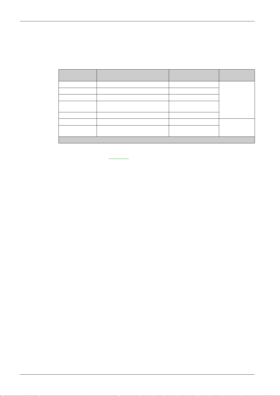
Title of documentation Reference number
EcoStruxure Machine Expert - HVAC software - Operating Guide
TM172 Optimized & Performance 7/18 IO Instruction Sheet
TM172 Performance 28/42 IO Instruction Sheet
TM172 Optimized & Performance Isolated 28/42 IO Instruction Sheet
TM172 Optimized & Performance Expansion 12/28 IO Instruction Sheet
TM172DCLW••• Display Color Touchscreen Instruction Sheet
TM172DCLF• Display Color Touchscreen Flush Mounting Instruction Sheet
.
EIO0000003412 (ENG)
QGH90428
NHA87740
PHA83703
QGH26895
QGH26896
PHA38669
before installing,
You can download these technical publications and other technical information from our website at
www.schneider-electric.com/en/download
.
EIO0000002015 02/2020 9
Page 10
Product Related Information
HAZARD OF ELECTRIC SHOCK, EXPLOSION OR ARC FLASH
Disconnect all power from all equipment including connected devices prior to removing any covers or
doors, or installing or removing any accessories, hardware, cables, or wires except under the specific
conditions specified in the appropriate hardware guide for this equipment.
Always use a properly rated voltage sensing device to confirm the power is off where and when
indicated.
Replace and secure all covers, accessories, hardware, cables, and wires and confirm that a proper
ground connection exists before applying power to the unit.
Use only the specified voltage when operating this equipment and any associated products.
Failure to follow these instructions will result in death or serious injury.
This equipment has been designed to operate outside of any hazardous location, and exclusive of
applications that generate, or have the potential to generate, hazardous atmospheres. Only install this
equipment in zones known to be free, at all times, of hazardous atmospheres.
POTENTIAL FOR EXPLOSION
Install and use this equipment in non-hazardous locations only.
Do not install and use this equipment in applications capable of generating hazardous atmospheres,
such as those applications employing flammable refrigerants.
Failure to follow these instructions will result in death or serious injury.
DANGER
DANGER
For information concerning the use of control equipment in applications capable of generating hazardous
materials, consult your local, regional, or national standards bureau or certification agency.
WARNING
LOSS OF CONTROL
The designer of any control scheme must consider the potential failure modes of control paths and,
for certain critical control functions, provide a means to achieve a safe state during and after a path
failure. Examples of critical control functions are emergency stop and overtravel stop, power outage
and restart.
Separate or redundant control paths must be provided for critical control functions.
System control paths may include communication links. Consideration must be given to the
implications of unanticipated transmission delays or failures of the link.
Observe all accident prevention regulations and local safety guidelines.
Each implementation of this equipment must be individually and thoroughly tested for proper operation
1
before being placed into service.
Failure to follow these instructions can result in death, serious injury, or equipment damage.
1
For additional information, refer to NEMA ICS 1.1 (latest edition), "Safety Guidelines for the Application,
Installation, and Maintenance of Solid State Control" and to NEMA ICS 7.1 (latest edition), "Safety
Standards for Construction and Guide for Selection, Installation and Operation of Adjustable-Speed Drive
Systems" or their equivalent governing your particular location.
WARNING
UNINTENDED EQUIPMENT OPERATION
Only use software approved by Schneider Electric for use with this equipment.
Update your application program every time you change the physical hardware configuration.
Failure to follow these instructions can result in death, serious injury, or equipment damage.
10 EIO0000002015 02/2020
Page 11
Terminology Derived from Standards
The technical terms, terminology, symbols and the corresponding descriptions in this manual, or that
appear in or on the products themselves, are generally derived from the terms or definitions of international
standards.
In the area of functional safety systems, drives and general automation, this may include, but is not limited
to, terms such as
message, dangerous
Among others, these standards include:
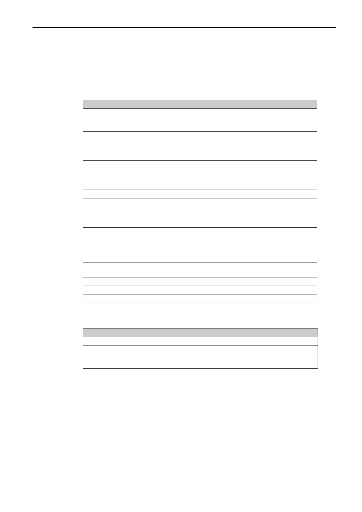
Standard Description
IEC 61131-2:2007 Programmable controllers, part 2: Equipment requirements and tests.
ISO 13849-1:2015 Safety of machinery: Safety related parts of control systems.
EN 61496-1:2013 Safety of machinery: Electro-sensitive protective equipment.
ISO 12100:2010 Safety of machinery - General principles for design - Risk assessment and risk
EN 60204-1:2006 Safety of machinery - Electrical equipment of machines - Part 1: General
ISO 14119:2013 Safety of machinery - Interlocking devices associated with guards - Principles
ISO 13850:2015 Safety of machinery - Emergency stop - Principles for design
IEC 62061:2015 Safety of machinery - Functional safety of safety-related electrical, electronic,
IEC 61508-1:2010 Functional safety of electrical/electronic/programmable electronic safety-
IEC 61508-2:2010 Functional safety of electrical/electronic/programmable electronic safety-
IEC 61508-3:2010 Functional safety of electrical/electronic/programmable electronic safety-
IEC 61784-3:2016 Industrial communication networks - Profiles - Part 3: Functional safety
2006/42/EC Machinery Directive
2014/30/EU Electromagnetic Compatibility Directive
2014/35/EU Low Voltage Directive
safety, safety function, safe state, fault, fault reset, malfunction, failure, error, error
, etc.
General principles for design.
Part 1: General requirements and tests.
reduction
requirements
for design and selection
and electronic programmable control systems
related systems: General requirements.
related systems: Requirements for electrical/electronic/programmable
electronic safety-related systems.
related systems: Software requirements.
fieldbuses - General rules and profile definitions.
In addition, terms used in the present document may tangentially be used as they are derived from other
standards such as:
Standard Description
IEC 60034 series Rotating electrical machines
IEC 61800 series Adjustable speed electrical power drive systems
IEC 61158 series Digital data communications for measurement and control – Fieldbus for use in
Finally, the term
zone of operation
is defined as it is for a
ISO 12100:2010
.
industrial control systems
may be used in conjunction with the description of specific hazards, and
hazard zone
or
danger zone
in the
Machinery Directive (2006/42/EC
) and
NOTE: The aforementioned standards may or may not apply to the specific products cited in the present
documentation. For more information concerning the individual standards applicable to the products
described herein, see the characteristics tables for those product references.
EIO0000002015 02/2020 11
Page 12

12 EIO0000002015 02/2020
Page 13

Modicon M172 Logic Controller
Overview
EIO0000002015 02/2020
Overview
Part I
Overview
EIO0000002015 02/2020 13
Page 14

Overview
14
EIO0000002015 02/2020
Page 15
Modicon M172 Logic Controller
M172 Range Overview
EIO0000002015 02/2020
M172 Range Overview
Chapter 1
M172 Range Overview
What Is in This Chapter?
This chapter contains the following topics:
Modicon M172 Logic Controller Offer Overview 16
Controller Range Overview 17
Expansion Modules Range Overview 19
Communication Modules Range Overview 20
Remote Display Range Overview 21
Accessories 23
Topic Page
EIO0000002015 02/2020 15
Page 16

M172 Range Overview
Modicon M172 Logic Controller Offer Overview
General Description
Modicon M172 Logic Controller are suitable for customized applications designed to control simple or
complex machines:
Air/water-cooled chiller
Rooftop unit
Heat pump
Compressor rack
Ventilation unit
The M172 offer is made of:
Controllers
Expansion modules
Communication modules
Remote displays
Accessories
Programming Software
In association with the controllers hardware, the EcoStruxure Machine Expert - HVAC development tool is
available to program and customize applications.
You can download EcoStruxure Machine Expert - HVAC - Programming Software for Modicon M171M172 Logic Controllers from
The use of several programming languages in accordance with IEC 61131-3 regulations (programming
standard for industrial control), makes it possible to develop new algorithms or entire programs easily,
which can then be uploaded to the M172 controllers via a PC and a Programming cable, helping to provide
confidentiality with appropriate security.
For more information, refer to Connection Types
(see page 17)
(see page 19)
(see page 20)
(see page 21)
(see page 23)
Schneider-electric web site download center
(seepage169)
.
.
16
EIO0000002015 02/2020
Page 17
Controller Range Overview
Type Code
Controller type code:
Type code description
TM172PDG42R TM172 P D G 42 R I
Product family TM172
Complementary
product family
Physical feature B = Blind
Embedded
Communication
Number of I/O 7
Digital output type R = Relays
Power supply
isolation
(1) Only for 28 and 42 I/O
(1)
M172 Range Overview
P = Performance
O = Optimized
D = Built-in Display
G = RS-485 and Ethernet based communication
protocols
M = RS-485 based communication protocols
18
28
42
S = Solid State Relays
(SSR) and Relays
I = Power
Supply
Isolated
EIO0000002015 02/2020 17
Page 18
M172 Range Overview
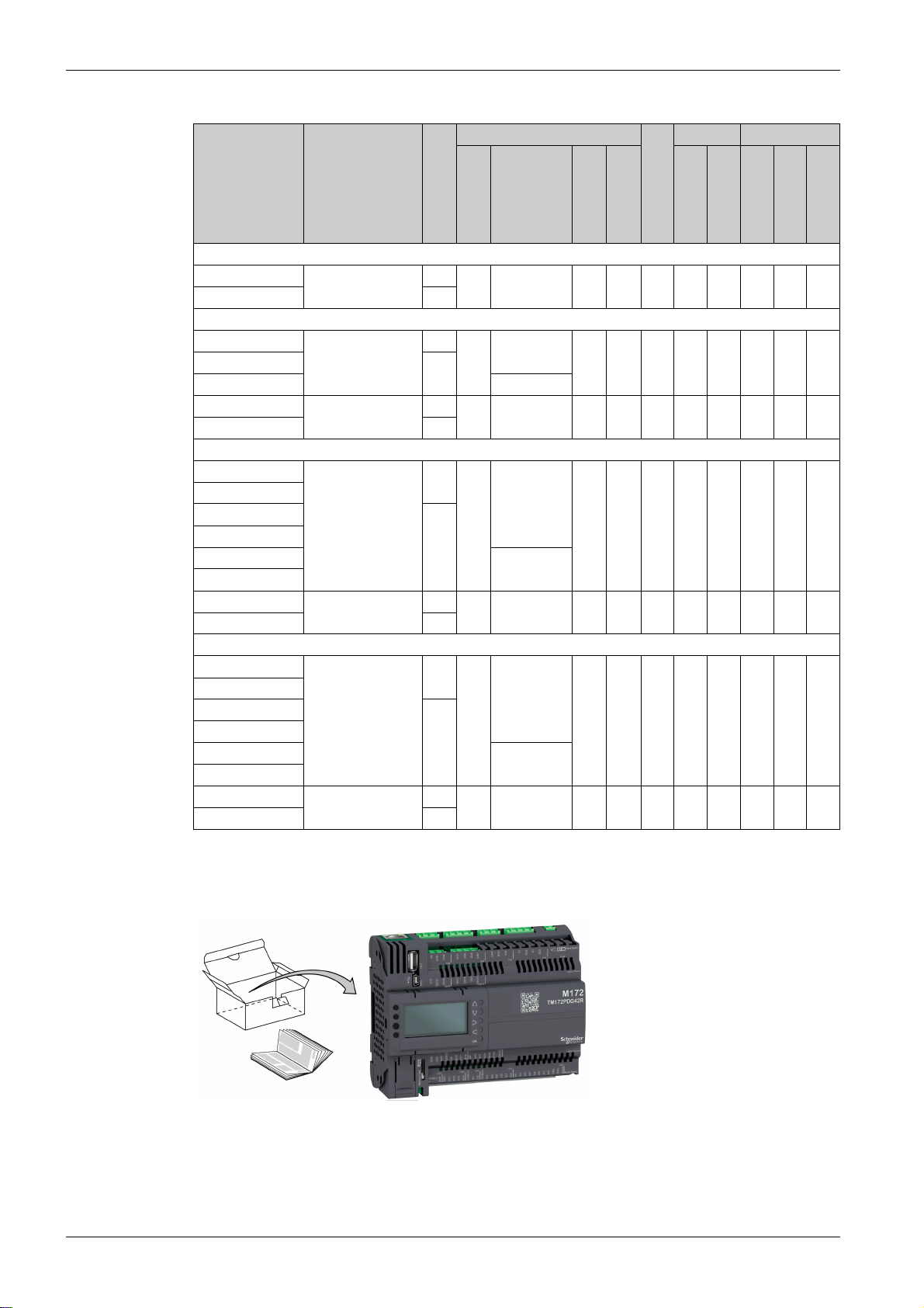
Controllers References
Reference Complementary
product family
Display
7 Inputs/Outputs
TM172PBG07R Performance - 2 3 2 0 ✓ ✓ ✓ ✓ ✓ ✓
TM172PDG07R ✓
18 Inputs/Outputs
TM172PBG18R Performance - 2 6 8 2 ✓ ✓ ✓ ✓ ✓ ✓
TM172PDG18R ✓
TM172PDG18S 4 + 2 SSR
TM172OBM18R Optimized - 2 6 8 2 - - ✓ ✓ - ✓
TM172ODM18R ✓
28 Inputs/Outputs
TM172PBG28R Performance - 8 8 8 4 ✓ ✓ ✓ ✓ ✓ ✓
TM172PBG28RI
TM172PDG28R ✓
TM172PDG28RI
TM172PDG28S 6 + 2 SSR
TM172PDG28SI
TM172OBM28R Optimized - 8 8 8 4 - - ✓ ✓ - ✓
TM172ODM28R ✓
42 Inputs/Outputs
TM172PBG42R Performance - 12 12 12 6 ✓ ✓ ✓ ✓ ✓ ✓
TM172PBG42RI
TM172PDG42R ✓
TM172PDG42RI
TM172PDG42S 10 + 2 SSR
TM172PDG42SI
TM172OBM42R Optimized - 12 12 12 6 - - ✓ ✓ - ✓
TM172ODM42R ✓
(see page 56)
(see page 58)
(see page 61)
(see page 64)
Inputs/Outputs
DI DO AI AO
USB Communication
Micro SD card
USB A
USB Mini-B
2 RS-485
1 Ethernet
1 CAN Exp. bus
The controller runs on 24 Vac/dc power supply.
TM172P•••••• / TM172O••••• Delivery Content
NOTE: Terminal blocks are not provided with the logic controllers and must be ordered separately
(see page 23)
18
EIO0000002015 02/2020
Page 19
Expansion Modules Range Overview
Type Code
Expansion module type code:
Type code description
TM172E28R TM172E 28 R
Product family TM172E
Number of I/O 12
Digital output type R = Relays
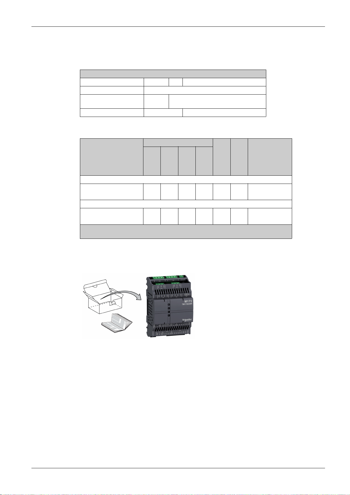
Expansion Modules References
Reference Inputs/Outputs
12 Inputs/Outputs
TM172E12R 2 6 4 - ✓ ✓
28 Inputs/Outputs
TM172E28R 6 10 10 2 ✓ ✓
(1) For service only.
(2) Also compatible with TM171P controller range.
(see page 68)
(see page 70)
28
DI DO AI AO
1 CAN Exp. bus
(1)
Compatible
controllers
1 TTL
TM172P••••••
TM172O•••••
TM172P••••••
TM172O•••••
M172 Range Overview
(2)
(2)
(2)
(2)
The expansion modules run on 24 Vac/dc power supply.
TM172E••R Delivery Content
NOTE: Terminal blocks are not provided with the expansion modules and must be ordered separately
(see page 23)
EIO0000002015 02/2020 19
Page 20
M172 Range Overview
Communication Modules Range Overview
Overview
This section presents communication modules.
Communication Modules References
Reference Description Terminal type Compatible
TM171ACAN CAN 2 screw terminal blocks TM172P••••••
TM171ALON LonWorks 1 screw terminal block
TM171AMB Modbus SL (RS-485) 2 screw terminal blocks
TM171ARS232 RS-232 serial link, Relay output 1 SUB-D 9
TM171ARS485 Modbus SL, and BACnet MS/TP 2 screw terminal blocks
TM171AETH Ethernet, Modbus TCP, and BACnet/IP 1 RJ45
TM171AETHRS485 Ethernet, Modbus TCP, BACnet/IP,
Modbus SL, and BACnet MS/TP
(1) Also compatible with TM171P controller range.
For further information about communication modules, refer to the Modicon M171A Communication
Modules Instruction Sheet
EAV96007
controllers
TM172O•••••
1 screw terminal block
TM172O•••••
1 RJ45
2 screw terminal blocks
(1)
(1)
.
20
EIO0000002015 02/2020
Page 21
Remote Display Range Overview
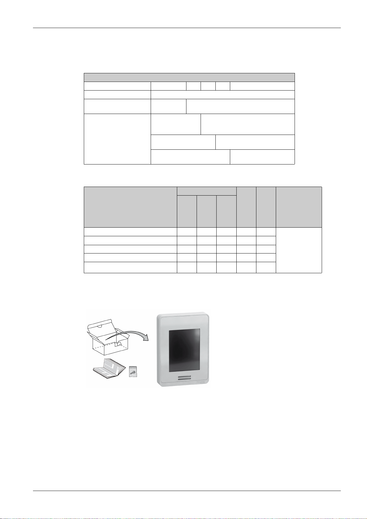
Type Code
Remote display type code:
Type code description
TM172DCLWTHP TM172DCL W T H P
Product family TM172DCL
Mounting type W = Vertical mounting
Characteristics G = Gray color
Remote Displays References
M172 Range Overview
F = Flush mounting
W = White color
T = Temperature sensor
None
H = Relative humidity sensor
None
P = Presence sensor (PIR)
Reference Embedded sensors
TM172DCLWT
TM172DCLWTH
TM172DCLWTHP
TM172DCLFG
TM172DCLFW
The remote displays run on 24 Vac/dc power supply.
TM172DCLWT•• Delivery Content
(see page 126)
(see page 126)
(see page 126)
(see page 127)
(see page 127)
Compatible
controllers
Temperature
✓ - - ✓ ✓ TM172P••••••
✓✓ - ✓✓
✓✓✓✓✓
---✓✓
---✓✓
Humidity
Presence
1 RS-485
1 USB Micro-B
TM172O•••••
TM171P•••••
TM171O•••••
Third-party
Modbus SL
devices
EIO0000002015 02/2020 21
Page 22

M172 Range Overview
TM172DCLF• Delivery Content
22
EIO0000002015 02/2020
Page 23

Accessories
Overview
This section describes the accessories and sensors.
Mounting and Wiring Accessories References
Description Use Reference
TM172DCLF• vertical surface support
for display
12 clips-on lock To install the TM172•••••• controllers
Screw terminal blocks for wiring of controllers and
expansion modules
USB cable type A / Mini-B 1.8 m (5.9 ft) To connect a PC to a TM172••••••
DIN adapter for current transducer 3240202000 To install the current transducer on a
(see page 32)
M172 Range Overview
Gray To install a TM172DCLF• on a vertical
White TM172ABKPW
3 m (9.84 ft) TCSXCNAMUM3P
surface
and the expansion modules on a
panel surface
For TM172P•G07R
For TM172•••18•
For TM172•••28••
For TM172•••42••
For TM172E12R
For TM172E28R
controller
DIN Rail Top Hat
(see page 46)
(see page 56)
(see page 58)
(see page 61)
(see page 64)
(see page 68)
(see page 70)
(see page 172)
TM172ABKPG
TM172AP12PM
TM172ASCTB07
TM172ASCTB18
TM172ASCTB28
TM172ASCTB42
TM172ASCTB12E
TM172ASCTB28E
BMXXCAUSBH018
3240301000
Sensors References
Description Cable length Reference
NTC IP68 5x20 mm (0.79 in.) -50+110°C (122…+230°F) Gray
NTC IP67 6x15 mm (0.591 in.) -50…+110°C (-122…+230°F) Gray 1.5 m (4.9 ft) TM1STNTCRN61515
NTC FAST IP67 4x40 mm (1.57 in.) -50+110°C (-122…+230°F) Gray 1.5 m (4.9 ft) TM1STNTCSF44015
NTC IP68 6x20 mm (0.79 in.) -50+110°C (-122…+230°F) Gray 1.5 m (4.9 ft) TM1STNTCSN62015
NTC IP68 6x20 mm (0.79 in.) TPE with strap Gray 1.5 m (4.9 ft) TM1STNTCTN62015
NTC for inside air -40...+60°C (-40...+140°F) Wall mounting - TM1STNTCWN75750
Pt1000 IP68 6x20 mm (0.79 in.) -50…+110°C (-122…+230°F) Green 1.5 m (4.9 ft) TM1STPTTSN52015
Pt1000 IP68 5x20 mm (0.79 in.) -50…+110°C (-122…+230°F) Green 1.5 m (4.9 ft) TM1STPTTSN62015
Humidity Probe Outdoor Wall mounting
4...20 mA (%RH)
Humidity and Temperature Probe Outdoor Wall mounting
4...20 mA (%RH) + NTC (Temp)
Humidity and Temperature Probe Outdoor Wall mounting
4...20 mA (%RH) + 4...20 mA (Temp)
Humidity and Temperature Probe Outdoor Wall mounting,
Dewpoint Calculation
Modbus SL RS485
NTC Temperature Probe Outdoor Wall mounting - TM1STNTCW69755
8 pieces 1.5 m (4.9 ft) TM1STNTCRN52015
100 pieces TM1STNTCRN5201P
5 pieces 3 m (9.8 ft) TM1STNTCRN52030
50 pieces TM1STNTCRN5203P
4 pieces 5 m (16.4 ft) TM1STNTCRN52050
25 pieces TM1STNTCRN5205P
3 m (9.8 ft) TM1STNTCRN61530
5 m (16.4 ft) TM1STNTCRN61550
3 m (9.8 ft) TM1STNTCSF44030
3 m (9.8 ft) TM1STNTCSN62030
5 m (16.4 ft) TM1STNTCSN62050
3 m (9.8 ft) TM1STNTCTN62030
3 m (9.8 ft) TM1STPTTSN52030
5 m (16.4 ft) TM1STPTTSN52050
3 m (9.8 ft) TM1STPTTSN62030
- TM1SHC4
-TM1SHTCN4
-TM1SHTCC4
TM1SHTM4
EIO0000002015 02/2020 23
Page 24

M172 Range Overview
24
EIO0000002015 02/2020
Page 25

What Is in This Part?
Modicon M172 Logic Controller
Global Features
EIO0000002015 02/2020
Global Features
Part II
Global Features
This part contains the following chapters:
Chapter Chapter Name Page
2 Before Starting 27
3 Wiring Best Practices 31
4 Installation 37
EIO0000002015 02/2020 25
Page 26

Global Features
26
EIO0000002015 02/2020
Page 27
Before Starting
Before Starting
Modicon M172 Logic Controller
Before Starting
EIO0000002015 02/2020
Before Starting
Chapter 2
Before Starting
Read and understand this chapter before beginning the installation of your system.
Pay particular attention in conforming to any safety information, different electrical requirements, and
normative standards that would apply to your machine or process in the use of this equipment.
The use and application of the information contained herein require expertise in the design and
programming of automated control systems. Only you, the user, machine builder or integrator, can be
aware of all the conditions and factors present during installation and setup, operation, and maintenance
of the machine or process, and can therefore determine the automation and associated equipment and the
related safeties and interlocks which can be effectively and properly used. When selecting automation and
control equipment, and any other related equipment or software, for a particular application, you must also
consider any applicable local, regional or national standards and/or regulations.
Disconnecting Power
WARNING
REGULATORY INCOMPATIBILITY
Ensure that all equipment applied and systems designed comply with all applicable local, regional, and
national regulations and standards.
Failure to follow these instructions can result in death, serious injury, or equipment damage.
All options and modules should be assembled and installed before installing the control system on a
mounting rail, onto a mounting plate or in a panel. Remove the control system from its mounting rail,
mounting plate or panel before disassembling the equipment.
DANGER
HAZARD OF ELECTRIC SHOCK, EXPLOSION OR ARC FLASH
Disconnect all power from all equipment including connected devices prior to removing any covers or
doors, or installing or removing any accessories, hardware, cables, or wires except under the specific
conditions specified in the appropriate hardware guide for this equipment.
Always use a properly rated voltage sensing device to confirm the power is off where and when
indicated.
Replace and secure all covers, accessories, hardware, cables, and wires and confirm that a proper
ground connection exists before applying power to the unit.
Use only the specified voltage when operating this equipment and any associated products.
Failure to follow these instructions will result in death or serious injury.
Programming Considerations
The products described in this manual have been designed and tested using Schneider Electric
programming, configuration, and maintenance software products.
WARNING
UNINTENDED EQUIPMENT OPERATION
Only use software approved by Schneider Electric for use with this equipment.
Update your application program every time you change the physical hardware configuration.
Failure to follow these instructions can result in death, serious injury, or equipment damage.
EIO0000002015 02/2020 27
Page 28
Before Starting
Operating Environment
This equipment has been designed to operate outside of any hazardous location, and exclusive of
applications that generate, or have the potential to generate, hazardous atmospheres. Only install this
equipment in zones known to be free, at all times, of hazardous atmospheres.
For information concerning the use of control equipment in applications capable of generating hazardous
materials, consult your local, regional, or national standards bureau or certification agency.
DANGER
POTENTIAL FOR EXPLOSION
Install and use this equipment in non-hazardous locations only.
Do not install and use this equipment in applications capable of generating hazardous atmospheres,
such as those applications employing flammable refrigerants.
Failure to follow these instructions will result in death or serious injury.
WARNING
UNINTENDED EQUIPMENT OPERATION
Install and operate this equipment according to the conditions described in the Environmental
Characteristics.
Failure to follow these instructions can result in death, serious injury, or equipment damage.
28
EIO0000002015 02/2020
Page 29
Installation Considerations
UNINTENDED EQUIPMENT OPERATION
Use appropriate safety interlocks where personnel and/or equipment hazards exist.
Install and operate this equipment in an enclosure appropriately rated for its intended environment and
secured by a keyed or tooled locking mechanism.
Use the sensor and actuator power supplies only for supplying power to the sensors or actuators
connected to the module.
Power line and output circuits must be wired and fused in compliance with local and national regulatory
requirements for the rated current and voltage of the particular equipment.
Do not use this equipment in safety-critical machine functions unless the equipment is otherwise
designated as functional safety equipment and conforming to applicable regulations and standards.
Do not disassemble, repair, or modify this equipment.
Do not connect any wiring to unused connections, or to connections designated as No Connection
(N.C.).
Failure to follow these instructions can result in death, serious injury, or equipment damage.
NOTE: JDYX2 or JDYX8 fuse types are UL-recognized and CSA approved.
The M172 controllers are intended for Top Hat Section Rail (DIN rail) mounting, panel mounting, or wall
mounting.
Care must be taken to avoid damage from electrostatic sources when handling this equipment. In particular
exposed connectors and, in some cases, exposed printed circuit boards are exceptionally vulnerable to
electrostatic discharge.
Before Starting
WARNING
WARNING
UNINTENDED EQUIPMENT OPERATION DUE TO ELECTROSTATIC DISCHARGE DAMAGE
Keep equipment in the protective conductive packaging until you are ready to install the equipment.
Only install equipment in approved enclosures and / or locations that prevent casual access and
provide electrostatic discharge protection.
Use a conductive wrist strap or equivalent field force protective device attached to an earth ground
when handling sensitive equipment.
Always discharge yourself by touching a grounded surface or approved antistatic mat before handling
the equipment.
Failure to follow these instructions can result in death, serious injury, or equipment damage.
For more information about enclosures, refer to the definition found in IEC 1000-4-2.
EIO0000002015 02/2020 29
Page 30

Before Starting
30
EIO0000002015 02/2020
Page 31

Modicon M172 Logic Controller
Wiring Best Practices
EIO0000002015 02/2020
Wiring Best Practices
Chapter 3
Wiring Best Practices
Wiring Best Practices
Wiring Best Practices
The following information describes the wiring guidelines and associated best practices to be respected
when using a Modicon M172 Logic Controller.
HAZARD OF ELECTRIC SHOCK, EXPLOSION OR ARC FLASH
Disconnect all power from all equipment including connected devices prior to removing any covers or
doors, or installing or removing any accessories, hardware, cables, or wires except under the specific
conditions specified in the appropriate hardware guide for this equipment.
Always use a properly rated voltage sensing device to confirm the power is off where and when
indicated.
Replace and secure all covers, accessories, hardware, cables, and wires and confirm that a proper
ground connection exists before applying power to the unit.
Use only the specified voltage when operating this equipment and any associated products.
Failure to follow these instructions will result in death or serious injury.
DANGER
WARNING
LOSS OF CONTROL
The designer of any control scheme must consider the potential failure modes of control paths and,
for certain critical control functions, provide a means to achieve a safe state during and after a path
failure. Examples of critical control functions are emergency stop and overtravel stop, power outage
and restart.
Separate or redundant control paths must be provided for critical control functions.
System control paths may include communication links. Consideration must be given to the
implications of unanticipated transmission delays or failures of the link.
Observe all accident prevention regulations and local safety guidelines.
Each implementation of this equipment must be individually and thoroughly tested for proper operation
before being placed into service.
Failure to follow these instructions can result in death, serious injury, or equipment damage.
1
For additional information, refer to NEMA ICS 1.1 (latest edition), "Safety Guidelines for the Application,
Installation, and Maintenance of Solid State Control" and to NEMA ICS 7.1 (latest edition), "Safety
Standards for Construction and Guide for Selection, Installation and Operation of Adjustable-Speed Drive
Systems" or their equivalent governing your particular location.
1
EIO0000002015 02/2020 31
Page 32

Wiring Best Practices
Wiring Guidelines
The following rules must be applied when wiring M172 offer product range:
I/O and communication wiring must be kept separate from the power wiring. Route these two types of
wiring in separate cable ducting.
Verify that the operating conditions and environment are within the specification values.
Use proper wire sizes to meet voltage and current requirements.
Use copper conductors (required).
Use twisted pair, shielded cables for analog, and/or fast I/O.
Use twisted pair, shielded cables for networks, and fieldbus.
Use shielded, properly grounded cables for all analog and high-speed inputs or outputs and
communication connections. If you do not use shielded cable for these connections, electromagnetic
interference can cause signal degradation. Degraded signals can cause the controller or attached modules
and equipment to perform in an unintended manner.
WARNING
UNINTENDED EQUIPMENT OPERATION
Use shielded cables for all fast I/O, analog I/O and communication signals.
Ground cable shields for all analog I/O, fast I/O and communication signals at a single point
Route communication and I/O cables separately from power cables.
Failure to follow these instructions can result in death, serious injury, or equipment damage.
1
.
1
Multipoint grounding is permissible if connections are made to an equipotential ground plane dimensioned
to help avoid cable shield damage in the event of power system short-circuit currents.
NOTE: Surface temperatures may exceed 60 °C (140 °F). Route primary wiring (wires connected to power
mains) separately and apart from secondary wiring (extra low voltage wiring coming from intervening
power sources). If that is not possible, double insulation is required such as conduit or cable gains.
Rules for Screw Terminal Block
The following table presents the cable types and wire sizes for a 5.08 mm (0.20 in.) or 5.00 mm (0.197 in.)
pitch screw terminal block:
The following table presents the cable types and wire sizes for a 3.81 mm (0.15 in.) or 3.50 mm (0.14 in.)
pitch screw terminal block:
32
The use of copper conductors is required.
EIO0000002015 02/2020
Page 33

LOOSE WIRING CAUSES ELECTRIC SHOCK
Tighten connections in conformance with the torque specifications.
Failure to follow these instructions will result in death or serious injury.
FIRE HAZARD
Use only the recommended wire sizes for the current capacity of the I/O channels and power supplies.
For relay output wiring up to 2 A, use conductors of at least 0.5 mm² (AWG 20) with a temperature
rating of at least 80 °C (176 °F).
For relay output wiring of 3 A, use conductors of at least 1.5 mm² (AWG 16) with a temperature rating
of at least 80 °C (176 °F).
For common conductors of relay output wiring of 9 A, or relay output wiring greater than 3 A, use
conductors of at least 2.0 mm² (AWG 12) with a temperature rating of at least 80 °C (176 °F).
Failure to follow these instructions can result in death, serious injury, or equipment damage.
Protecting Outputs from Inductive Load Damage
Depending on the load, a protection circuit may be needed for the relay outputs. Inductive loads using DC
voltages may create voltage reflections resulting in overshoot that will damage or shorten the life of output
devices.
Wiring Best Practices
DANGER
WARNING
CAUTION
OUTPUT CIRCUIT DAMAGE DUE TO INDUCTIVE LOADS
Use an appropriate external protective circuit or device to reduce the risk of inductive direct current load
damage.
Failure to follow these instructions can result in injury or equipment damage.
Choose a protection circuit from the following diagrams according to the power supply used. Connect the
protection circuit to the outside of the controller or relay output module.
If your controller or module contains relay outputs, these types of outputs can support up to 240 Vac.
Inductive damage to these types of outputs can result in welded contacts and loss of control. Each
inductive load must include a protection device such as a peak limiter, RC circuit or flyback diode.
Capacitive loads are not supported by these relays.
WARNING
RELAY OUTPUTS WELDED CLOSED
Always protect relay outputs from inductive alternating current load damage using an appropriate
external protective circuit or device.
Do not connect relay outputs to capacitive loads.
Failure to follow these instructions can result in death, serious injury, or equipment damage.
Protective circuit A: this protection circuit can be used for both AC and DC load power circuits.
C Value from 0.1 to 1 μF
R Resistor of approximately the same resistance value as the load
EIO0000002015 02/2020 33
Page 34

Wiring Best Practices
Protective circuit B: this protection circuit can be used for DC load power circuits.
Use a diode with the following ratings:
Reverse withstand voltage: power voltage of the load circuit x 10.
Forward current: more than the load current.
Protective circuit C: this protection circuit can be used for both AC and DC load power circuits.
In applications where the inductive load is switched on and off frequently and/or rapidly, verify that the
continuous energy rating (J) of the varistor exceeds the peak load energy by 20 % or more.
NOTE: Place protection devices as close to the load as possible.
Special Handling Considerations
Care must be taken to avoid damage from electrostatic sources when handling this equipment. In particular
exposed connectors and, in some cases, exposed printed circuit boards are exceptionally vulnerable to
electrostatic discharge.
UNINTENDED EQUIPMENT OPERATION DUE TO ELECTROSTATIC DISCHARGE DAMAGE
Keep equipment in the protective conductive packaging until you are ready to install the equipment.
Only install equipment in approved enclosures and / or locations that prevent casual access and
provide electrostatic discharge protection.
Use a conductive wrist strap or equivalent field force protective device attached to an earth ground
when handling sensitive equipment.
Always discharge yourself by touching a grounded surface or approved antistatic mat before handling
the equipment.
Failure to follow these instructions can result in death, serious injury, or equipment damage.
WARNING
34
EIO0000002015 02/2020
Page 35

Analog Inputs-Probes
Wiring Best Practices
Temperature probes have no connection polarity and can be extended using a normal bipolar cable.
The extension of the probes wiring influences the electromagnetic compatibility (EMC) of the instrument
Verify the polarity for probes which have a specific connection polarity.
NOTICE
INOPERABLE EQUIPMENT
Verify all wiring connections before applying power.
Failure to follow these instructions can result in equipment damage.
Do not power any connected devices that are externally powered without also applying power to the M172.
NOTICE
INOPERABLE EQUIPMENT
Ensure that the controller has power applied when applying power to other connected and externally
powered devices.
Failure to follow these instructions can result in equipment damage.
Signal leads (probes, digital inputs, communication, and the electronic supply) must be routed separately
from power cables.
EIO0000002015 02/2020 35
Page 36

Wiring Best Practices
36
EIO0000002015 02/2020
Page 37

Modicon M172 Logic Controller
Installation
EIO0000002015 02/2020
Installation
Chapter 4
Installation
What Is in This Chapter?
This chapter contains the following topics:
TM172•••07• / TM172•••18• Controllers Mounting Positions 38
TM172•••28•• / TM172•••42•• Controllers Mounting Positions 39
TM172E••R Expansion Modules Mounting Positions 40
Controllers and Expansion Modules Clearances 41
Top Hat Section Rail (DIN Rail) 42
Controllers and Expansion Modules Installation 45
TM172DCLWT•• Remote Display Installation 47
TM172DCLF• Remote Display Installation 48
Topic Page
EIO0000002015 02/2020 37
Page 38

Installation
TM172•••07• / TM172•••18• Controllers Mounting Positions
Correct Mounting Position
TM172•••07• / TM172•••18• controllers must be mounted horizontally on a vertical plane as shown in the
figure below:
Incorrect Mounting Position
TM172•••07• / TM172•••18• controllers cannot be mounted neither vertically, nor horizontally backward:
38
EIO0000002015 02/2020
Page 39

TM172•••28•• / TM172•••42•• Controllers Mounting Positions
Correct Mounting Position
TM172•••28•• / TM172•••42•• controllers should be mounted horizontally on a vertical plane as shown in
the figure below:
Acceptable Mounting Position
TM172•••28R• / TM172•••42R• controllers can be mounted horizontally upward with a temperature
derating (maximum ambient temperature: 60 °C (140 °F)).
TM172PDG28SI / TM172PDG42SI controllers can be mounted horizontally upward with a temperature
derating (maximum ambient temperature: 55 °C (131 °F)).
Installation
Incorrect Mounting Position
TM172•••28•• / TM172•••42•• controllers cannot be mounted neither vertically, nor horizontally backward:
TM172PDG28S / TM172PDG42S controllers cannot be mounted horizontally upward:
EIO0000002015 02/2020 39
Page 40

Installation
TM172E••R Expansion Modules Mounting Positions
Correct Mounting Position
TM172E••R expansion modules must be mounted horizontally on a vertical plane or horizontally upward
as shown in the figure below:
Incorrect Mounting Position
TM172E••R expansion modules cannot be mounted neither vertically, nor horizontally backward:
40
EIO0000002015 02/2020
Page 41

Controllers and Expansion Modules Clearances
Minimum Clearances
UNINTENDED EQUIPMENT OPERATION
Place devices dissipating the most heat at the top of the cabinet and ensure adequate ventilation.
Avoid placing this equipment next to or above devices that might cause overheating.
Install the equipment in a location providing the minimum clearances from all adjacent structures and
equipment as directed in this document.
Install all equipment in accordance with the specifications in the related documentation.
Failure to follow these instructions can result in death, serious injury, or equipment damage.
TM172•••••• controllers and expansion modules have been designed as IP20 products and must be
installed in an enclosure appropriately rated for its intended environment and secured by a keyed or tooled
locking mechanism .
There are 3 types of clearances between:
The M172 device and the sides of the cabinet (including the panel door).
The M172 device terminal blocks and the wiring ducts. This distance reduces electromagnetic
interference between the controller and the wiring ducts.
The M172 device and other heat generating devices installed in the same cabinet.
The following figure shows the minimum clearances that apply to TM172•••••• references:
Installation
WARNING
EIO0000002015 02/2020 41
Page 42

Installation
Top Hat Section Rail (DIN Rail)
Dimensions of Top Hat Section Rail (DIN Rail)
You can mount the controller and expansion module on a 35 mm (1.38 in.) top hat section rail (DIN rail). It
can be attached to a smooth mounting surface or suspended from a EIA rack or mounted in a NEMA
cabinet.
Symmetric Top Hat Section Rails (DIN Rail)
The following illustration and table show the references of the top hat section rails (DIN rail) for the wallmounting range:
Reference Type Rail length (B)
NSYSDR50A A 450 mm (17.71 in.)
NSYSDR60A A 550 mm (21.65 in.)
NSYSDR80A A 750 mm (29.52 in.)
NSYSDR100A A 950 mm (37.40 in.)
The following illustration and table show the references of the symmetric top hat section rails (DIN rail) for
the metal enclosure range:
Reference Type Rail length (B-12 mm)
NSYSDR60 A 588 mm (23.15 in.)
NSYSDR80 A 788 mm (31.02 in.)
NSYSDR100 A 988 mm (38.89 in.)
NSYSDR120 A 1188 mm (46.77 in.)
42
EIO0000002015 02/2020
Page 43

Installation
The following illustration and table shows the references of the symmetric top hat section rails (DIN rail) of
2000 mm (78.74 in.):
Reference Type Rail length
NSYSDR200
NSYSDR200D
1
2
1 Unperforated galvanized steel
2 Perforated galvanized steel
A 2000 mm (78.74 in.)
A
EIO0000002015 02/2020 43
Page 44

Installation
Double-Profile Top Hat Section Rails (DIN Rail)
The following illustration and table show the references of the double-profile top hat section rails (DIN rails)
for the wall-mounting range:
Reference Type Rail length (B)
NSYDPR25 W 250 mm (9.84 in.)
NSYDPR35 W 350 mm (13.77 in.)
NSYDPR45 W 450 mm (17.71 in.)
NSYDPR55 W 550 mm (21.65 in.)
NSYDPR65 W 650 mm (25.60 in.)
NSYDPR75 W 750 mm (29.52 in.)
The following illustration and table show the references of the double-profile top hat section rails (DIN rail)
for the floor-standing range:
Reference Type Rail length (B)
NSYDPR60 F 588 mm (23.15 in.)
NSYDPR80 F 788 mm (31.02 in.)
NSYDPR100 F 988 mm (38.89 in.)
NSYDPR120 F 1188 mm (46.77 in.)
44
EIO0000002015 02/2020
Page 45

Controllers and Expansion Modules Installation
Overview
This section describes how to install and remove a TM172•••••• controller or expansion module from a top
hat section rail (DIN rail).
Installing on a Top Hat Section Rail (DIN Rail)
The following procedure describes how to install a controller or an expansion module on a top hat section
rail (DIN rail):
Step Action
1 Move the two spring docking devices to their standby position (use a screwdriver to press
against the relative compartments).
2 Position the top groove of the controller or the expansion modules on the top edge of the Top
Hat Section Rail (DIN rail).
3 Press the assembly against the Top Hat Section Rail (DIN rail).
4 Press the spring docking devices to put them into the locked position.
Installation
Removing from a Top Hat Section Rail (DIN Rail)
The following procedure describes how to remove a controller or an expansion module from a top hat
section rail (DIN rail):
Step Action
1 Remove the power from the controller or the expansion module.
2 Insert a flat screwdriver into the spring docking devices.
3 Pull down the spring docking device to move it to its standby position.
4 Pull the controller or the expansion module from the top hat section rail (DIN rail) from the
bottom.
EIO0000002015 02/2020 45
Page 46

Installation
Panel Installation
To install the controllers and expansion modules on a panel you must use clip-on locks.
NOTE: Upper clip-on locks are not provided with the logic controllers and must be ordered separately
(see page 23)
. Only one additional upper clip-on lock is necessary for TM172P•G07R, TM172•••18•, and
TM172E••R.
The following procedure shows how to install a TM172•••28•• or a TM172•••42•• controller on a panel using
the clip-on locks. The same procedure shall be followed for the TM172P•••••• / TM172O••••• / TM172E••R:
Step Action
1 Install the 2 upper clip-on locks
2 Move the 2 lower clip-on locks to their standby position
Mounting Holes Layout
3 Secure the device in position with 4 screws.
Refer to the mounting holes layout
TM172•••07•
TM172•••18•
TM172E••R
TM172•••28••
TM172•••42••
(see page 46)
.
46
EIO0000002015 02/2020
Page 47

TM172DCLWT•• Remote Display Installation
TM172DCLWT•• Panel installation
The TM172DCLWT•• remote display can be mounted horizontally or vertically on a vertical wall.
TM172DCLWT•• display incorporates a temperature sensor. To function correctly, air must circulate
through the product to accurately determine the temperature.
INACCURATE TEMPERATURE MEASUREMENT
Mount the TM172DCLWT•• in an upright, vertical (portrait) position when using the temperature sensor.
Failure to follow these instructions can result in equipment damage.
The following graphic and procedure explain how to install TM172DCLWT•• remote display on a wall:
Installation
NOTICE
Mounting Holes Layout
Mounting holes layout for TM172DCLWT••:
Step Action
1 Open unit by pulling on bottom side of the display(1)
2 Ensure correct side of base faces up
3 Pull cables 150 mm (5.90 in.) out from wall
4 Align base and mark location of two mounting holes on wall or panel (2)
5 Install anchors in wall (3)
6 Insert cable in central hole of base
7 Place rear cover on the wall and align it with mounting holes (4)
8 Insert screws in mounting holes on each side of base (5)
9 Strip each wire 6 mm (0.24 in.) from end
10 Insert each wire according to wiring chart
11 Gently push excess wiring back into hole
12 Gently align cover to top of base and snap in place from bottom (6)
13 Install the isolated screw connection for securing the plastic housing (7)
(see page 31)
EIO0000002015 02/2020 47
Page 48

Installation
TM172DCLF• Remote Display Installation
TM172DCLF• Wiring
The TM172DCLF• remote display must be wired prior to the mounting phase.
The following procedure explain how to wire a TM172DCLF• remote display:
Step Action
1 Open unit by pulling on bottom side of the display
2 Insert cable in central hole of base
3 Strip each wire 6 mm (0.24 in.) from end
4 Insert each wire according to wiring chart
5 Gently align cover to top of base and snap in place.
6 Install the 4 isolated screws connection for securing the plastic housing
(see page 31)
TM172DCLF• Panel Installation
The TM172DCLF• remote display can be mounted horizontally or vertically on a vertical panel.
The following procedure explain how to install a TM172DCLF• remote display on a panel:
Step Action
1 Make a hole using the mounting hole layout.
2 Pull cables 150 mm (5.90 in.) out from hole.
3 Wire the unit according to the wiring procedure.
4 Insert the unit in the hole (1).
5 Secure it with 4 panel mounting locks provided (2)(3).
48
EIO0000002015 02/2020
Page 49

TM172DCLF• Vertical Surface Installation
The TM172DCLF• remote display can be mounted horizontally or vertically on a vertical surface using
TM172ABKPG or TM172ABKPW accessory.
The following procedure explain how to install TM172DCLF• remote display on a vertical surface:
Step Action
1 Place the TM172ABKP• accessory.
2 Ensure correct side of TM172ABKP• faces up.
3 Pull cables 150 mm (5.90 in.) out from vertical surface if necessary.
4 Align TM172ABKP• and mark location of two mounting holes on the vertical surface.
5 Drill holes in the vertical surface (1).
6 Pull cables 150 mm (5.90 in.) out from a hole of TM172ABKP•.
7 Place TM172ABKP• on the vertical surface and align it with mounting holes.
8 Insert screws in mounting holes on each side of TM172ABKP• (2).
9 Wire the unit according to the wiring procedure.
10 Gently push excess wiring back into hole.
11 Gently snap in place TM172DCLF• into TM172ABKP• (3).
Installation
TM172DCLF• Top Hat Section Rail (DIN Rail) Installation
The TM172DCLF• remote display can be mounted horizontally on a top hat section rail (DIN rail).
The following procedure describes how to install a TM172DCLF• remote display on a top hat section rail
(DIN rail):
Step Action
1 Wire the unit according to the wiring procedure.
2 Position the top groove of the remote display on the top edge of the Top Hat Section Rail (DIN
rail) (1).
3 Press the assembly against the Top Hat Section Rail (DIN rail) (2) up to the locked position (3).
EIO0000002015 02/2020 49
Page 50

Installation
Mounting Holes Layout
Mounting hole layout for TM172DCLF•: with seals: without seals:
Mounting holes layout for TM172ABKPG or TM172ABKPW:
50
EIO0000002015 02/2020
Page 51

What Is in This Part?
Modicon M172 Logic Controller
Controllers and Expansion Modules
EIO0000002015 02/2020
Controllers and Expansion Modules
Part III
Controllers and Expansion Modules
This part contains the following chapters:
Chapter Chapter Name Page
5 Environmental Characteristics 53
6 TM172P•••••• / TM172O••••• Controllers Description 55
7 TM172E••R Expansion Modules Description 67
8 Electrical Characteristics and Wiring Diagrams 73
9 User Interface 119
EIO0000002015 02/2020 51
Page 52

Controllers and Expansion Modules
52
EIO0000002015 02/2020
Page 53

Modicon M172 Logic Controller
Environmental
EIO0000002015 02/2020
Environmental Characteristics
Chapter 5
Environmental Characteristics
Environmental Characteristics
Technical Data
The Modicon M172 Logic Controller offer components meet European Community (CE) requirements for
open equipment. You must install them in an enclosure or other location designed for the specific
environmental conditions and to minimize the possibility of unintended contact with hazardous voltages.
Use metal enclosures to improve the electromagnetic immunity of your M172 system. This equipment
meets CE requirements as indicated in the following tables.
UNINTENDED EQUIPMENT OPERATION
Do not exceed any of the rated values specified within this chapter.
Failure to follow these instructions can result in death, serious injury, or equipment damage.
WARNING
Controller and Expansion Modules Specifications
Characteristics Specification
The product complies with the
following harmonized
Standards
Construction of control Electronic automatic
Purpose of control Operating control
Mounting Top Hat Section Rail (DIN rail) ✓
Type of action 1.B ✓
Type of disconnection or
suspension for each circuit
Pollution degree 2 (normal) ✓
Over-voltage category II ✓
Rated impulse voltage 2500 V ✓
Period of electric stress on the
insulating parts
TM172E12R
TM172E28R
TM172PDG28S / TM172PDG42S
TM172P•G18R / TM172O•M18R
TM172O••28R
TM172PDG18S
TM172P•G07R
EN 60730-1 / EN 60730-2-9 ✓
Incorporated Control
(non-safety-related)
Optional panel mounting (with
accessories
1.Y -✓-✓-✓-✓-
Micro disconnection ✓
Long period, EN 60730 ✓
TM172O••42R
TM172PDG28SI
TM172PBG28RI / TM172PDG28RI
✓
✓
✓
TM172PDG42SI
TM172P•G28R / TM172P•G42R
TM172PBG42RI / TM172PDG42RI
EIO0000002015 02/2020 53
Page 54

Environmental
Characteristics Specification
TM172P•G07R
TM172PDG18S
TM172O••28R
TM172PDG28SI
TM172O••42R
TM172PDG42SI
TM172E12R
TM172E28R
TM172P•G28R / TM172P•G42R
TM172PBG42RI / TM172PDG42RI
TM172PDG28S / TM172PDG42S
Power supply 24 Vac (+/- 10 %) 50 Hz /
TM172P•G18R / TM172O•M18R
TM172PBG28RI / TM172PDG28RI
-✓
60 Hz
20…38 Vdc
(non-isolated)
24 Vac (+/- 10 %) 50 Hz /
✓60 Hz
20…38 Vdc
(isolated)
Power Consumption 20 VA / 10 W ✓ - ✓ -
21 VA / 11 W - ✓ -
23 VA / 12 W - ✓ -
24 VA / 15 W - ✓
25 VA / 14 W - ✓ -
35 VA / 15 W - ✓ -
Insulation class II ✓
Ambient operating temperature -20…55 °C (-4…131 °F) - ✓ - ✓ -
Ambient operating humidity
(2)
✓
(1)
-
-20…60 °C (-4…140 °F) ✓ -
-20…65 °C (-4…149 °F) -
✓
5…95 % ✓
✓
(2)
-
✓
(1)
-
-✓
✓
(3)
-
(non-condensing)
Ambient storage temperature -30…70 °C (-22…158 °F) ✓
Ambient storage humidity
5…95 % ✓
(non-condensing)
Temperature for ball pressure
125 °C (257 °F) ✓ - ✓
test
Insulation material group IIIa ✓
Fire-resistance category D ✓
Software class and structure A ✓
Digital outputs Refer to the label on the
✓
device
Degree of protection by
IP20 ✓
enclosure
(1) Limited to 55°C (131°F), if mounted other than horizontally on vertical plane.
(2) Limited to 60°C (140°F), if mounted other than horizontally on vertical plane.
(3) Limited to 60°C (140°F), if DO8 is active or if mounted other than horizontally on vertical plane.
54
EIO0000002015 02/2020
Page 55

Modicon M172 Logic Controller
TM172P•••••• / TM172O••••• Contro llers Description
EIO0000002015 02/2020
TM172P•••••• / TM172O••••• Controllers Description
Chapter 6
TM172P•••••• / TM172O••••• Controllers Description
What Is in This Chapter?
This chapter contains the following topics:
TM172P•G07R 56
TM172P••18• / TM172O••18• 58
TM172P••28•• / TM172O••28R 61
TM172P••42•• / TM172O••42R 64
Topic Page
EIO0000002015 02/2020 55
Page 56

TM172P•••••• / TM172O••••• Controllers Description
TM172P•G07R
Overview
Reference Description
TM172PBG07R M172 Performance Blind 7 I/Os Isolated
TM172PDG07R M172 Performance Display 7 I/Os Isolated
Physical Description
The following illustration presents the TM172P•G07R controller:
Number Name Description
1 CN6 DO3 High voltage relay digital output 250 Vac 3 A SPDT
CN9 DO1…DO2 High voltage relay digital output 250 Vac 3 A SPST
2 CN10 24 Vac/dc isolated power supply
3 CN5 Power out +24 Vdc power out for analog inputs, max current 100mA
+5 Vdc power out for ratiometric analog inputs, max current 40 mA
AI1…AI2 Analog inputs are configurable as
NTC resistive input or digital input
Current analog input
Voltage analog input
PTC resistive input
4 - Clip-on lock
6 CN3 DI1…DI2 Fast digital input, pulse/frequency counter up 2 kHz, opto-isolated
8 CN1 RS-485 serial port-2
CN19 RS-485 serial port-1
9 CN18 CAN expansion bus master
10 - Micro SD memory card slot
11 - Service battery door
12 -
13 - Communication module connector
14 -
15 -
16 CN16 USB type Mini-B female for PC connection
17 CN17 USB type A female for a mass storage device (FAT32)
18 CN20 Ethernet Modbus TCP/IP or BACnet IP
(1) Only for TM172•D•••••.
(2) 0-5 V Ratiometric: ratiometric range is 0.5 V to 4.5 V. Maximum current at +5 Vdc is 40 mA.
User interface - Display
User interface - LEDs
User interface - Keys
(see page 37)
(see page 109)
(see page 109)
(see page 117)
(see page 119)
(see page 119)
(see page 119)
(see page 75)
(see page 90)
(see page 105)
(see page 115)
(1)
(see page 20)
(1)
(1)
(see page 111)
(see page 111)
(see page 112)
(see page 87)
(see page 83)
:
(2)
(see page 79)
56
NOTE: The controller is delivered without removable screw terminal blocks
(see page 23)
EIO0000002015 02/2020
.
Page 57

TM172P•••••• / TM172O••••• Controllers Description
NOTICE
INOPERABLE EQUIPMENT
Configure the analog inputs and outputs, and related parameters, according to the physical types of
resources connected.
Failure to follow these instructions can result in equipment damage.
For more details, refer to analog inputs configuration
(see page 99)
For more information about the wiring, refer to wiring best practices
Dimension
Mounting Holes Layout
(seepage90)
.
and analog outputs configuration
(see page 31)
.
EIO0000002015 02/2020 57
Page 58

TM172P•••••• / TM172O••••• Controllers Description
TM172P••18• / TM172O••18•
Overview
Reference Description
TM172PBG18R M172 Performance Blind 18 I/Os Isolated
TM172PDG18R M172 Performance Display 18 I/Os Isolated
TM172PDG18S M172 Performance Display 18 I/Os 2 SSR Isolated
TM172OBM18R M172 Optimized Blind 18 I/Os Isolated
TM172ODM18R M172 Optimized Display 18 I/Os Isolated
58
EIO0000002015 02/2020
Page 59

Physical Description
TM172P•••••• / TM172O••••• Controllers Description
The following illustration presents the TM172•••18• controller:
Number Name Description
1 CN6 DO3 High voltage relay digital output 250 Vac 3 A SPDT
CN9 DO1…DO2 High voltage relay digital output 250 Vac 3 A SPST
CN15 DO4…DO5
TM172•••••R•: High voltage relay digital output 250 Vac 3 A SPST
TM172PDG18S: High voltage SSR digital output 240 Vac 0.2 A
DO6 High voltage relay digital output 250 Vac 3 A SPST
2 CN10 24 Vac/dc isolated power supply
(see page 75)
(see page 87)
(see page 83)
(see page 83)
3 CN5 Power out +24 Vdc power out for analog inputs, max current 100mA
+5 Vdc power out for ratiometric analog inputs, max current 40 mA
AI1…AI2 Analog inputs are configurable as
CN13 AI3…AI8
4 - Clip-on lock
NTC resistive input or digital input
Current analog input
Voltage analog input
PTC resistive input
(see page 37)
(see page 90)
:
6 CN3 DI1…DI2 Fast digital input, pulse/frequency counter up 2 kHz, opto-isolated
7 CN11 AO1…AO2 Low voltage SELV analog outputs, configurable as
Current modulation analog output
Current ON/OFF analog output
Voltage modulation analog output
PWM open collector
8 CN1 RS-485 serial port-2
CN19 RS-485 serial port-1
9 CN18 CAN expansion bus master
10 -
Micro SD memory card slot
11 - Service battery door
12 -
User interface - Display
13 - Communication module connector
14 -
15 -
User interface - LEDs
User interface - Keys
16 CN16 USB type Mini-B female for PC connection
17 CN17
18 CN20
USB type A female for a mass storage device (FAT32)
Ethernet Modbus TCP/IP or BACnet IP
(see page 109)
(see page 109)
(see page 105)
(see page 115)
(see page 117)
(see page 119)
(see page 119)
(see page 119)
(3)
(1)
(see page 20)
(1)
(1)
(see page 111)
(see page 112)
(see page 111)
(3)
(see page 99)
(3)
(1) Only for TM172•D•••••.
(2) 0-5 V Ratiometric: ratiometric range is 0.5 V to 4.5 V. Maximum current at +5 Vdc is 40 mA.
(3) Only for TM172P••••••.
(see page 83)
(see page 86)
(2)
(see page 79)
:
NOTE: The controller is delivered without removable screw terminal blocks
EIO0000002015 02/2020 59
(see page 23)
.
Page 60

TM172P•••••• / TM172O••••• Controllers Description
INOPERABLE EQUIPMENT
Configure the analog inputs and outputs, and related parameters, according to the physical types of
resources connected.
Failure to follow these instructions can result in equipment damage.
NOTICE
For more details, refer to analog inputs configuration
(see page 99)
For more information about the wiring, refer to wiring best practices
Dimension
Mounting Holes Layout
(seepage90)
.
and analog outputs configuration
(see page 31)
.
60
EIO0000002015 02/2020
Page 61

TM172P•••••• / TM172O••••• Controllers Description
TM172P••28•• / TM172O••28R
Overview
Reference Description
TM172PBG28R M172 Performance Blind 28 I/Os
TM172PBG28RI M172 Performance Blind 28 I/Os Isolated
TM172PDG28R M172 Performance Display 28 I/Os
TM172PDG28RI M172 Performance Display 28 I/Os Isolated
TM172PDG28S M172 Performance Display 28 I/Os 2 SSR
TM172PDG28SI M172 Performance Display 28 I/Os 2 SSR Isolated
TM172OBM28R M172 Optimized Blind 28 I/Os Isolated
TM172ODM28R M172 Optimized Display 28 I/Os Isolated
Physical Description
The following illustration presents the TM172P••28•• controller:
TM172P••28• controller: TM172P••28•I / TM172O••28R controller:
Number Name Description
1 CN6 DO8
TM172P••28•: High voltage relay digital output 250 Vac 1 A SPDT
(see page 87)
TM172P••28•I / TM172O••28R: High voltage relay digital output 250 Vac 3 A
(see page 87)
SPDT
CN7 DO5…DO7 High voltage relay digital output 250 Vac 3 A SPST
CN8 DO3…DO4
CN9 DO1…DO2
TM172•••••R•: High voltage relay digital output 250 Vac 3 A SPST
(see page 83)
(see page 83)
TM172•••••S•: High voltage SSR digital output 240 Vac 0.5 A
2 CN10 24 Vac/dc power supply
(1) Only for TM172•D•••••.
(2) 0-5 V Ratiometric: ratiometric range is 0.5 V to 4.5 V. Maximum current at +5 Vdc is 50 mA.
(3) Only for TM172P••••••.
EIO0000002015 02/2020 61
(see page 75)
(see page 86)
Page 62

TM172P•••••• / TM172O••••• Controllers Description
Number Name Description
3 CN5 Power out +24 Vdc power out for analog inputs, max current 150mA
AI1…AI8 Analog inputs are configurable as
4 - Clip-on lock
5 CN4 DI3…DI8 Regular digital input opto-isolated
6 CN3 DI1…DI2 Fast digital input, pulse/frequency counter up 2 kHz, opto-isolated
7 CN2 AO1…AO2 Low voltage (SELV) analog outputs 0…10 Vdc
AO3…AO4 Low voltage SELV analog outputs, configurable as
8 CN1 RS-485 serial port-2
CN19 RS-485 serial port-1
9 CN18 CAN expansion bus master
10 -
11 - Service battery door
12 -
13 - Communication module connector
14 -
15 -
16 CN16 USB type Mini-B female for PC connection
17 CN17
18 CN20
(1) Only for TM172•D•••••.
(2) 0-5 V Ratiometric: ratiometric range is 0.5 V to 4.5 V. Maximum current at +5 Vdc is 50 mA.
(3) Only for TM172P••••••.
Micro SD memory card slot
User interface - Display
User interface - LEDs
User interface - Keys
USB type A female for a mass storage device (FAT32)
Ethernet Modbus TCP/IP or BACnet IP
+5 Vdc power out for ratiometric analog inputs, max current 50 mA
(see page 90)
NTC resistive input or digital input
Current analog input
Voltage analog input
PTC resistive input
:
(see page 37)
(see page 80)
(see page 101)
(see page 99)
Current modulation analog output
Current ON/OFF analog output
Voltage modulation analog output
PWM open collector
(see page 109)
(see page 109)
(see page 105)
(see page 115)
(3)
(see page 117)
(see page 119)
(1)
(see page 20)
(see page 119)
(see page 119)
(1)
(1)
(see page 111)
(3)
(see page 112)
(see page 111)
(3)
(2)
(see page 79)
:
NOTE: The controller is delivered without removable screw terminal blocks
(see page 23)
.
NOTICE
INOPERABLE EQUIPMENT
Configure the analog inputs and outputs, and related parameters, according to the physical types of
resources connected.
Failure to follow these instructions can result in equipment damage.
For more details, refer to analog inputs configuration
(see page 99)
.
For more information about the wiring, refer to wiring best practices
(seepage90)
and analog outputs configuration
(see page 31)
.
62
EIO0000002015 02/2020
Page 63

Dimension
Mounting Holes Layout
TM172P•••••• / TM172O••••• Controllers Description
EIO0000002015 02/2020 63
Page 64

TM172P•••••• / TM172O••••• Controllers Description
TM172P••42•• / TM172O••42R
Overview
Reference Description
TM172PBG42R M172 Performance Blind 42 I/Os
TM172PBG42RI M172 Performance Blind 42 I/Os Isolated
TM172PDG42R M172 Performance Display 42 I/Os
TM172PDG42RI M172 Performance Display 42 I/Os Isolated
TM172PDG42S M172 Performance Display 42 I/Os 2 SSR
TM172PDG42SI M172 Performance Display 42 I/Os 2 SSR Isolated
TM172OBM42R M172 Optimized Blind 42 I/Os Isolated
TM172ODM42R M172 Optimized Display 42 I/Os Isolated
Physical Description
The following illustration presents the TM172•••42•• controller:
TM172P••42• controller: TM172P••42•I / TM172O••42R controller:
64
EIO0000002015 02/2020
Page 65

TM172P•••••• / TM172O••••• Controllers Description
Number Name Description
1 CN6 DO8
TM172P••42•: High voltage relay digital output 250 Vac 1 A SPDT
(see page 87)
TM172P••42•I / TM172O••42R: High voltage relay digital output 250 Vac 3 A
SPDT
(see page 87)
CN7 DO5…DO7 High voltage relay digital output 250 Vac 3 A SPST
(see page 83)
CN8 DO3…DO4
CN9 DO1…DO2
TM172•••••R•: High voltage relay digital output 250 Vac 3 A SPST
(see page 83)
TM172•••••S•: High voltage SSR digital output 240 Vac 0.5 A
CN14 DO12 TM172P••42•: High voltage relay digital output 250 Vac 1 A SPDT
(see page 86)
(see page 87)
TM172P••42•I / TM172O••42R: High voltage relay digital output 250 Vac 3 A
SPDT
(see page 87)
CN15 DO9…DO11 High voltage relay digital output 250 Vac 3 A SPST
2 CN10 24 Vac/dc power supply
3 CN5 Power out
(see page 75)
+24 Vdc power out for analog inputs, max current 150 mA
+5 Vdc power out for ratiometric analog inputs, max current 50 mA
AI1…AI8 Analog inputs are configurable as
NTC resistive input or digital input
Current analog input
Voltage analog input
PTC resistive input
(see page 90)
(see page 83)
(3)
(2)(3)
:
CN13 AI9…AI12 Identical to CN5.
Power out
4 - Clip-on lock
5 CN4 DI3…DI8 Regular digital input opto-isolated
(see page 37)
(see page 80)
CN12 DI9…DI12
6 CN3 DI1…DI2 Fast digital input, pulse/frequency counter up 2 kHz, opto-isolated
7 CN2 AO1…AO2 Low voltage (SELV) analog outputs 0…10 Vdc
AO3…AO4 Low voltage SELV analog outputs, configurable as
Current modulation analog output
Current ON/OFF analog output
Voltage modulation analog output
PWM open collector
CN11 AO5…AO6 Low voltage (SELV) analog outputs 0…10 Vdc
8 CN1 RS-485 serial port-2
CN19 RS-485 serial port-1
9 CN18 CAN expansion bus master
10 -
Micro SD memory card slot
11 - Service battery door
12 -
User interface - Display
13 - Communication module connector
14 -
15 -
User interface - LEDs
User interface - Keys
16 CN16 USB type Mini-B female for PC connection
17 CN17
18 CN20
USB type A female for a mass storage device (FAT32)
Ethernet Modbus TCP/IP or BACnet IP
(see page 109)
(see page 109)
(see page 105)
(see page 115)
(see page 117)
(see page 119)
(see page 119)
(see page 119)
(4)
(1)
(see page 20)
(1)
(1)
(see page 111)
(see page 112)
(see page 101)
(see page 99)
(see page 101)
(see page 111)
(4)
(4)
(see page 79)
:
(1) Only for TM172•D•••••.
(2) 0-5 V Ratiometric: ratiometric range is 0.5 V to 4.5 V. Maximum current at +5 Vdc is 50 mA.
(3) The maximum current value is the sum between the maximum currents supplied by the corresponding terminals in
the CN5 connector and in the CN13 connector.
(4) Only for TM172P••••••.
NOTE: The controller is delivered without removable screw terminal blocks
EIO0000002015 02/2020 65
(see page 23)
.
Page 66

TM172P•••••• / TM172O••••• Controllers Description
INOPERABLE EQUIPMENT
Configure the analog inputs and outputs, and related parameters, according to the physical types of
resources connected.
Failure to follow these instructions can result in equipment damage.
NOTICE
For more details, refer to analog inputs configuration
(see page 99)
For more information about the wiring, refer to wiring best practices
Dimension
Mounting Holes Layout
(seepage90)
.
and analog outputs configuration
(see page 31)
.
66
EIO0000002015 02/2020
Page 67

Modicon M172 Logic Controller
TM172E••R Expansion Modules Description
EIO0000002015 02/2020
TM172E••R Expansion Modules Description
Chapter 7
TM172E••R Expansion Modules Description
What Is in This Chapter?
This chapter contains the following topics:
TM172E12R 68
TM172E28R 70
Topic Page
EIO0000002015 02/2020 67
Page 68

TM172E••R Expansion Modules Description
TM172E12R
Physical Description
The following illustration presents the TM172E12R expansion module:
Number Name Description
1 CN4 DO4…DO6 High voltage relay digital output 250 Vac 3 A SPST
CN5 DO1…DO3
2 CN6 24 Vac/dc non-isolated power supply
3 CN3 Power out +24 Vdc power out for analog inputs, max current 125mA
+5 Vdc power out for ratiometric analog inputs, max current 50 mA
AI1…AI4 Analog inputs are configurable as
4 - Clip-on lock
5 CN2 DI1…DI2 Fast digital input, pulse/frequency counter up 2 kHz, opto-isolated
6 - CAN configuration 6-position DIP switches
9 CN1 CAN expansion bus slave
13 - TTL Port (Service only)
(1) 0-5 V Ratiometric: ratiometric range is 0.5 V to 4.5 V. Maximum current at +5 Vdc is 50 mA.
NTC resistive input or digital input
Current analog input
Voltage analog input
PTC resistive input
(see page 37)
(see page 105)
(see page 75)
(see page 90)
(see page 106)
NOTE: The expansion module is delivered without removable screw terminal blocks
(see page 83)
(1)
:
(see page 79)
(see page 23)
NOTICE
INOPERABLE EQUIPMENT
Configure the analog inputs and outputs, and related parameters, according to the physical types of
resources connected.
Failure to follow these instructions can result in equipment damage.
.
68
For more details, refer to analog inputs configuration
(see page 99)
.
(seepage90)
For more information about the wiring, refer to wiring best practices
and analog outputs configuration
(see page 31)
.
EIO0000002015 02/2020
Page 69

Dimension
Mounting Holes Layout
TM172E••R Expansion Modules Description
EIO0000002015 02/2020 69
Page 70

TM172E••R Expansion Modules Description
TM172E28R
Physical Description
The following illustration presents the TM172E28R expansion module:
Number Name Description
1 CN4 DO4…DO6 High voltage relay digital output 250 Vac 3 A SPST
(see page 83)
CN5 DO1…DO3
CN10 DO9…DO10
CN11 DO7…DO8
2 CN6 24 Vac/dc non-isolated power supply
3 CN3 Power out
+24 Vdc power out for analog inputs, max current 125 mA
+5 Vdc power out for ratiometric analog inputs, max current 50 mA
AI1…AI4 Analog inputs are configurable as
NTC resistive input or digital input
Current analog input
Voltage analog input
PTC resistive input
(see page 75)
(see page 90)
(2)
(1)(2)
:
CN9 AI5…AI10 Identical to CN3.
Power out
4 - Clip-on lock
5 CN2 DI1…DI2 Fast digital input, pulse/frequency counter up 2 kHz, opto-isolated
CN8 DI3…DI6 Regular digital input opto-isolated
6 - CAN configuration 6-position DIP switches
7 CN7 AO1…AO2 Low voltage SELV analog outputs, configurable as
9 CN1 CAN expansion bus slave
(see page 37)
(see page 106)
Current modulation analog output
Current ON/OFF analog output
Voltage modulation analog output
PWM open collector
(see page 105)
(see page 80)
(see page 99)
(see page 79)
:
13 - TTL Port (Service only)
(1) 0-5 V Ratiometric: ratiometric range is 0.5 V to 4.5 V. Maximum current at +5 Vdc is 50 mA.
(2) The maximum current value is the sum between the maximum currents supplied by the corresponding terminals in
the CN3 connector and in the CN9 connector.
70
NOTE: The expansion module is delivered without removable screw terminal blocks
(see page 23)
EIO0000002015 02/2020
.
Page 71

TM172E••R Expansion Modules Description
NOTICE
INOPERABLE EQUIPMENT
Configure the analog inputs and outputs, and related parameters, according to the physical types of
resources connected.
Failure to follow these instructions can result in equipment damage.
For more details, refer to analog inputs configuration
(see page 99)
For more information about the wiring, refer to wiring best practices
Dimension
Mounting Holes Layout
(seepage90)
.
and analog outputs configuration
(see page 31)
.
EIO0000002015 02/2020 71
Page 72

TM172E••R Expansion Modules Description
72
EIO0000002015 02/2020
Page 73

Modicon M172 Logic Controller
Electrical Characteristics and Wiring Diagrams
EIO0000002015 02/2020
Electrical Characteristics and Wiring Diagrams
Chapter 8
Electrical Characteristics and Wiring Diagrams
From time to time, new input modules, output modules, or other devices are made available that are not
documented in the present documentation. For information on new devices, contact your local Schneider
Electric representative.
NOTICE
INOPERABLE EQUIPMENT
Update the controller firmware to the latest version every time you install a newly released Input/Output
expansion module or other device to this equipment.
Failure to follow these instructions can result in equipment damage.
NOTE: For more information on how to update the controller firmware, contact your local Schneider
Electric representative.
Applying incorrect current or voltage levels on TM172P••07• / TM172P••18• / TM172O••18• / TM172P••28•I
/ TM172O••28R / TM172P••42•I / TM172O••42R controllers and TM172E••R expansion modules inputs
and outputs could damage the electronic circuitry. Further, connecting a current input device to an analog
input configured for voltage, and vice versa, could damage the electronic circuitry.
NOTICE
INOPERABLE EQUIPMENT
Do not apply current above 30 mA to the analog inputs of the expansion module.
Do not apply voltages above 24 Vdc and less than -7 Vdc to the analog inputs of the expansion
module.
Do not mismatch the applied signal with the analog input configuration.
Failure to follow these instructions can result in equipment damage.
Applying incorrect current or voltage levels on TM172P••28•• / TM172P••42•• controllers analog inputs and
outputs could damage the electronic circuitry. Further, connecting a current input device to an analog input
configured for voltage, and vice versa, could damage the electronic circuitry.
NOTICE
INOPERABLE EQUIPMENT
Do not apply current above 25 mA to the analog inputs of the controller or Input/Output expansion
module.
Do not apply voltages above 11 Vdc to the analog inputs of the controller or Input/Output expansion
module.
Do not mismatch the applied signal with the analog input configuration.
Failure to follow these instructions can result in equipment damage.
EIO0000002015 02/2020 73
Page 74

Electrical Characteristics and Wiring Diagrams
What Is in This Chapter?
This chapter contains the following sections:
Section Topic Page
8.1 Power Supply 75
8.2 Digital Input 78
8.3 Digital Output 82
8.4 Analog Inputs 89
8.5 Analog Outputs 98
8.6 Communication 104
8.7 Memory 115
8.8 RTC (Real-Time Clock) 117
74
EIO0000002015 02/2020
Page 75

Power Supply
Section 8.1
Power Supply
Power Supply
Controllers and Expansion Modules Power Supply
References Power supply characteristics Maximum power
TM172P•G07R controller Isolated 24 Vac (+/- 10 %) - 50/60 Hz 20 VA
TM172P•G18• / TM172O•M18R
controllers
TM172P••28•I / TM172O••28R
controllers
TM172P••42•I / TM172O••42R
controllers
TM172P••28• / TM172P••42•
controllers
TM172E12R expansion module 24 Vac (+/- 10 %) - 50/60 Hz 20 VA
TM172E28R expansion module 24 Vac (+/- 10 %) - 50/60 Hz 24 VA
Electrical Characteristics and Wiring Diagrams
consumption
20…38 Vdc 10 W
24 Vac (+/- 10 %) - 50/60 Hz 21 VA
20…38 Vdc 11 W
24 Vac (+/- 10 %) - 50/60 Hz 23 VA
20…38 Vdc 12 W
24 Vac (+/- 10 %) - 50/60 Hz 25 VA
20…38 Vdc 14 W
Non-isolated 24 Vac (+/- 10 %) - 50/60 Hz 35 VA
20…38 Vdc 15 W
20…38 Vdc 10 W
20…38 Vdc 15 W
Power supply wiring diagram:
24 Vac 24 Vdc
(1) Type T fuse 2 A.
Pitch of the terminal block Cabling length
3.50 mm (0.14 in.) 10 m (32.8 ft)
NOTICE
INOPERABLE EQUIPMENT
Do not connect a power cable longer than 10 m (32.8 ft).
Failure to follow these instructions can result in equipment damage.
For more information about the wiring, refer to Best wiring practices
(see page 31)
The power supplies for the TM172P••••••, TM172O•••••, and TM172E••R must be rated Safety Extra Low
Voltage (SELV) according to IEC 61140. These sources of power are isolated between the electrical input
and output circuits of the power supply as well as simple separation from ground (earth), PELV, and other
SELV systems.
.
EIO0000002015 02/2020 75
Page 76

Electrical Characteristics and Wiring Diagrams
GROUND LOOP CAUSING ELECTRIC SHOCK AND/OR INOPERABLE EQUIPMENT
Do not connect the 0 V power supply/transformer connection supplying this equipment to any external
ground (earth) connection.
Do not connect any 0 V or ground (earth) of the sensors and actuators connected to this equipment to
any external ground connection.
If necessary, use separate power supplies/transformers to power sensors or actuators isolated from
this equipment.
Failure to follow these instructions will result in death or serious injury.
In all cases, if the specified voltage range is not maintained, the products may not function as intended.
Use appropriate safety interlocks and voltage monitoring circuits.
POTENTIAL OF OVERHEATING AND FIRE
Do not connect the equipment directly to line voltage.
Use only isolating SELV, Class 2 power supplies / transformers to supply power to this equipment.
Failure to follow these instructions can result in death, serious injury, or equipment damage.
DANGER
WARNING
76
EIO0000002015 02/2020
Page 77

Electrical Characteristics and Wiring Diagrams
Power Supply and Field bus Wiring Restriction For Non Isolated Controllers and Expansion Modules
TM172P••28• / TM172P••42• / TM172E••R power supply inputs are not isolated. If you connect the GND
connection of the RS-485 network or the CAN expansion bus across multiple controllers, you must use
separate, isolated power supplies. Alternatively, if you are interconnecting the equipment to a single power
supply, do not connect the RS-485 or CAN GND signal. Pay special attention when connecting serial lines.
Miswiring may lead to inoperable equipment.
CAN network example with separate power lines:
CAN network example with common power line and GND signal not connected:
NOTE: TM172P•G07R / TM172•••18• / TM172O••28R / TM172O••42R / TM172P••28•I / TM172P••42•I
power supply inputs are isolated. GS connection of the RS-485 network or the GND connection of the CAN
expansion bus across multiple controllers must be connected regardless of the power supply type and
wiring.
EIO0000002015 02/2020 77
Page 78

Electrical Characteristics and Wiring Diagrams
Digital Input
Section 8.2
Digital Input
Digital Inputs
This table presents the digital inputs of controllers and expansion modules:
Description
Fast digital inputs
Regular digital inputs
These devices have analog inputs that can be configured as dry contact digital inputs. For more details,
refer to the configuration of analog inputs
NOTE: The commons COM_DI are not internally connected together.
What Is in This Section?
This section contains the following topics:
Fast Digital Inputs 79
Regular Digital Inputs 80
(see page 79)
(see page 80)
TM172P•G07R
TM172•••18R
TM172•••18S
TM172•••28R•
TM172•••28S•
TM172•••42R•
TM172•••42S•
TM172E12R
222222222
- - - 6 6 10 10 - 4
(seepage90)
Topic Page
.
TM172E28R
78
EIO0000002015 02/2020
Page 79

Fast Digital Inputs
Overview
Characteristics
Electrical Characteristics and Wiring Diagrams
If fast digital inputs are used as regular digital inputs, refer to regular digital inputs wiring diagram
(see page 80)
.
The table indicates the digital inputs characteristics:
Characteristic Value
Used as fast input Used as regular input
Type Digital input
Power draw (maximum) 5 mA
Working voltage +0…38 Vdc +0…38 Vdc
Pulse detection minimum length Positive pulse 0.15 ms Positive or negative pulse:
Maximum frequency measurement 2 kHz -
Logic type Digital inputs work in
positive logic
Level 1 +20…38 Vdc +20…38 Vdc
Level 0 +0…4 Vdc +0…4 Vdc
0…24 Vac +/-10 % 50/60 Hz
TM172P••07• / TM172•••18•: 40 ms
TM172•••28•• / TM172•••42••: 20 ms
TM172E28R: 40 ms
Digital inputs work in positive or negative
logic
24 Vac +/-10 % 50/60 Hz
0…3 Vac 50/60 Hz
Logic type description
Logic type Active state
Positive logic Output supplies current (source output)
Negative logic Output draws current (sink output)
Wiring Diagram Example
TM172•••07• / TM172•••18• / TM172•••28•• / TM172•••42•• (CN3) fast digital input:
Pitch of the terminal block Cabling length
3.50 mm (0.14 in) 10 m (32.808 ft)
For more information about the wiring, refer to Best wiring practices
Related Devices and Connectors
The table indicates the related devices and connectors
Current flows to the input (sink input)
Current flows from the input (source input)
(see page 31)
.
Related Device Connector Label Description
TM172•••07•
TM172•••18•
TM172•••28••
TM172•••42••
TM172E••R CN2
EIO0000002015 02/2020 79
CN3 COM-DI Common for digital inputs 1…2
DI1…DI2 Regular digital inputs 1…2
Page 80

Electrical Characteristics and Wiring Diagrams
Regular Digital Inputs
Characteristics
The table indicates the digital inputs characteristics:
Characteristic Value
Type Digital input
Power draw (maximum) 5 mA
Working voltage +0…38 Vdc
Pulse detection minimum length
Logic type Digital inputs work in positive logic
Level 1 +20…38 Vdc
Level 0 +0…4 Vdc
0…24 Vac +/-10 % 50/60 Hz
TM172•••28••/TM172•••42•• positive or negative pulse
DI3…DI4: 20 ms
DI5…DI8: 40 ms
TM172•••42•• positive or negative pulse
DI9…DI12: 40 ms
TM172E28R positive pulse
DI3…DI6: 40 ms
TM172•••28••/TM172•••42••: Digital inputs work in positive or
negative logic
TM172E28R: Digital inputs work in positive logic
24 Vac +/-10 % 50/60 Hz
0…3 Vac 50/60 Hz
Logic type description
Logic type Active state
Positive logic Output supplies current (source output)
Negative logic Output draws current (sink output)
Wiring Diagram Example
TM172•••28•• / TM172•••42•• (CN4) regular digital input:
Pitch of the terminal block Cabling length
3.50 mm (0.14 in) 10 m (32.808 ft)
For more information about the wiring, refer to Best wiring practices
Current flows to the input (sink input)
Current flows from the input (source input)
(see page 31)
.
80
EIO0000002015 02/2020
Page 81

Related Devices and Connectors
The table indicates the related devices and connectors
Electrical Characteristics and Wiring Diagrams
Related
Device
TM172•••28••
TM172•••42••
TM172•••42•• CN12 COM-DI Common for digital inputs 9…12
TM172E28R CN8 COM-DI Common for digital inputs 3…6
Connector Label Description
CN4 COM-DI Common for digital inputs 3…8
DI3…DI8 Regular digital inputs 3…8
DI9…DI12 Regular digital inputs 9…12
DI3…DI6 Regular digital inputs 3…6
EIO0000002015 02/2020 81
Page 82

Electrical Characteristics and Wiring Diagrams
Digital Output
Section 8.3
Digital Output
Digital Output
This table presents the digital outputs of controllers and expansion modules:
Description
High voltage relay SPST digital output
High voltage Solid-state relay digital output
High voltage relay SPDT digital output
These devices have analog outputs that can be configured as low voltage (SELV), open collector outputs.
For more details, refer to the configuration of analog outputs
NOTE: The commons Cx are not internally connected together.
(see page 83)
(see page 86)
(see page 87)
TM172P•G07R
TM172•••18R
TM172•••18S
TM172•••28R•
TM172•••28S•
TM172•••42R•
TM172•••42S•
TM172E12R
TM172E28R
2 5 3 7 5108 610
--2-2-2- -
1111122- -
(see page 90)
.
What Is in This Section?
This section contains the following topics:
High voltage Relay SPST Digital Output 83
High Voltage Solid-State Relay Digital Output 86
High voltage Relay SPDT Digital Output 87
Topic Page
82
EIO0000002015 02/2020
Page 83

High voltage Relay SPST Digital Output
Characteristics
The table indicates the digital outputs characteristics:
Characteristic Value
Maximum voltage 250 Vac
Maximum current 3 A resistive load, 2 FLA / 12 LRA
Minimum switching capacity 100 mA / 5 Vdc
Electrical durability conforming to UL60730 100 000 cycles, 3 A at 250 Vac
Wiring Diagram Example
TM172•••28•• (CN7) SPST relay output:
Electrical Characteristics and Wiring Diagrams
Pitch of the terminal block
5.00 mm (0.197 in)
For more information about the wiring, refer to Best wiring practices
(see page 31)
.
EIO0000002015 02/2020 83
Page 84

Electrical Characteristics and Wiring Diagrams
Related Devices and Connectors
The table indicates the related devices and connectors
Related Device Connector Label Description
TM172•••07•
TM172•••18•
TM172•••18R CN15 C4 Common for output relay 4
TM172•••18S CN15 C6 Common for output relay 6
CN9 C12 Common for output relays 1…2
Maximum current: 6 A
DO1…DO2 Output relays 1…2
Maximum current: 3 A
C5 Common for output relay 5
Maximum current: 3 A
C6 Common for output relay 6
Maximum current: 3 A
DO4…DO6 Output relays 4…6
Maximum current: 3 A
DO6 Output relay 6
NOTE: DO4 and DO5 are SSR
outputs
(see page 86)
.
TM172•••28••
TM172•••42••
TM172•••28R•
TM172•••42R•
TM172•••42•• CN15 C91011 Common for output relays 9…11
TM172E••R CN5 C123 Common for output relays 1…3
CN7 C567 Common for output relays 5…7
Maximum current: 9 A
DO5…DO7 Output relays 5…7
CN8 C34 Common for output relays 3…4
Maximum current: 6 A
DO3…DO4 Output relays 3…4
CN9 C1 Common for output relay 1
Maximum current: 3 A
C2 Common for output relay 2
Maximum current: 3 A
DO1…DO2 Output relays 1…2
Maximum current: 9 A
DO9…DO11 Output relays 9…11
Maximum current: 9 A
DO1…DO3 Output relays 1…3
84
CN4 C456 Common for output relays 4…6
Maximum current: 9 A
DO4…DO6 Output relays 4…6
EIO0000002015 02/2020
Page 85

Electrical Characteristics and Wiring Diagrams
Related Device Connector Label Description
TM172E28R CN11 C78 Common for output relays 7…8
Maximum current: 6 A
DO7…DO8 Output relays 7…8
CN10 C910 Common for output relays 9…10
Maximum current: 6 A
DO9…DO10 Output relays 9…10
EIO0000002015 02/2020 85
Page 86

Electrical Characteristics and Wiring Diagrams
High Voltage Solid-State Relay Digital Output
Characteristics
The table indicates the SSR output characteristics:
Characteristic Value
Nominal voltage 75…240 Vac
Maximum current 0.2 A 0.5 A
Switching rate range 45…65 Hz
Minimum switching capacity 20 mA
Wiring Diagram Example
TM172•••28S• (CN9) SSR output:
TM172•••18S TM172•••28S•
TM172•••42S•
Pitch of the terminal block
5.00 mm (0.197 in)
For more information about the wiring, refer to Best wiring practices
Related Devices and Connectors
The table indicates the related devices and connectors
Related Device Connector Label Description
TM172•••18S CN15 C4 Common for SSR output 4
TM172•••28S•
TM172•••42S•
(see page 31)
Maximum current: 0.2 A
C5 Common for SSR output 5
Maximum current: 0.2 A
DO4…DO5 SSR Outputs 4…5
.
NOTE: DO6 is not an SSR output.
(see page 84)
CN9 C1 Common for SSR output 1
Maximum current: 0.5 A
C2 Common for SSR output 2
Maximum current: 0.5 A
DO1…DO2 SSR Outputs 1…2
86
EIO0000002015 02/2020
Page 87

High voltage Relay SPDT Digital Output
Characteristics
The table indicates the digital outputs characteristics:
Characteristic Value
TM172•••07•
TM172•••18•
TM172P••28•I
TM172P••42•I
TM172O••28R
TM172O••42R
Maximum voltage 250 Vac 240 Vac
Maximum current 3 A resistive load,
NO contact: 2.2 FLA / 13.2 LRA
Minimum switching
capacity
Electrical durability
conforming to UL60730
300 mA, resistive load 300 mA, resistive load
100 000 cycles 100 000 cycles
Electrical Characteristics and Wiring Diagrams
TM172P••28•
TM172P••42•
-20…55 °C (-4…131 °F): 3 A resistive load
-20…60 °C (-4…140 °F): 1 A resistive load
-20…65 °C (-4…149 °F): 1 A resistive load if
DO8 is inactive
Wiring Diagram Example
TM172•••28•• / TM172•••42•• (CN6) SPDT relay output:
Pitch of the terminal block
5.00 mm (0.197 in)
For more information about the wiring, refer to Best wiring practices
(see page 31)
.
EIO0000002015 02/2020 87
Page 88

Electrical Characteristics and Wiring Diagrams
Related Devices and Connectors
The table indicates the related devices and connectors
Related Device Connector Label Description
TM172•••07•
TM172•••18•
CN6 C3 Common for output relay 3
Maximum current: 3 A
DO3 Output relay3 - Normally open
DO3- Output relay 3 - Normally closed
TM172•••28••
TM172•••42••
CN6 C8 Common for output relay 8
Maximum current: 3 A
(1)(2)
DO8 Output relay 8 - Normally open
DO8- Output relay 8 - Normally closed
TM172•••42•• CN14 C12 Common for output relay 12
Maximum current: 3 A
(1)
DO12 Output relay 12 - Normally open
DO12- Output relay 12 - Normally closed
(1) TM172P••28• / TM172P••42•: The maximum current is limited to 1 A if the ambient temperature exceeds 55 °C
(131 °F).
(2) TM172P••28• / TM172P••42•: The ambient temperature must not exceed 60 °C (140 °F) if DO8 is active.
88
EIO0000002015 02/2020
Page 89

Analog Inputs
Section 8.4
Analog Inputs
Analog Inputs
This table presents the analog inputs of controllers and expansion modules:
Description
Configurable analog inputs or digital input. 288881212410
What Is in This Section?
This section contains the following topics:
Analog Inputs 90
NTC Analog Input 93
Resistive Analog Input 94
Current Analog Input 95
Voltage Analog Input 96
Analog Input Used as Digital Input 97
Electrical Characteristics and Wiring Diagrams
TM172P•G07R
TM172•••18R
TM172•••18S
TM172•••28R•
TM172•••28S•
TM172•••42R•
TM172•••42S•
TM172E12R
TM172E28R
Topic Page
EIO0000002015 02/2020 89
Page 90

Electrical Characteristics and Wiring Diagrams
Analog Inputs
Overview
Controllers analog inputs are identified as AI1…AIx.
The inputs are configurable in pairs, AI1- AI2 is the first pair, AI3-AI4 is the second pair, and so on, up to
the last pair. Both AIs of a pair must be configured in order to belong to the same type group.
Using the parameter Cfg_Aix, an analog input AIx can be configured to acquire a signal by a physical
resource (probe, digital input, voltage/current signal) as specified in the following table:
Type group
NTC resistive input
(see page 93)
or
Digital input
Current input
(see page 97)
(see page 95)
Voltage input 0…10 Vdc
Cfg_Aix
0 NTC (NK103), 10 kΩ at 25 °C, BETA value 3977
1 Digital input
2 NTC (103AT-2), 10 kΩ at 25 °C, BETA value 3435
7
3 4…20 mA
11 0…20 mA
40…10Vdc
Description
hΩ (NTC)
(1)
(see page 96)
Voltage input 0…5 Vdc
(see page 96)
Resistive input
(see page 94)
(1) Resistance value read, expressed in 0.1 kΩ, for a resistance applied to the input using the controller in
NTC configuration, for example creating a divider with pull-up resistance of 10 kΩ. The resistance range
for the hΩ(NTC) configuration is up to 150 kΩ.
(2) Resistance value read, expressed in 0.01 kΩ, for a resistance applied to the input using the controller in
Pt1000 configuration, that is, creating a divider with pull-up resistance (1.5 kΩ for TM172P•G07R /
TM172•••18•, 2 kΩ for other device references). The resistance range for the daΩ (Pt1000) configuration
is up to 3 kΩ.
5 0…5 Vdc Ratiometric
10 0…5 Vdc
6 Pt1000
8
9 PTC (KTY81)
daΩ (Pt1000)
(2)
The analog inputs configured as digital inputs are not isolated.
NOTICE
INOPERABLE EQUIPMENT
Only use voltage free type inputs on analog inputs configured as digital inputs.
Failure to follow these instructions can result in equipment damage.
90
EIO0000002015 02/2020
Page 91

Compatibility in Pairs
Electrical Characteristics and Wiring Diagrams
Parameters by pair
Pairs Parameter Set
Pair #1
Pair #2
Pair #3
Pair #4
Pair #5
Pair #6
Cfg_Ai1 Cfg_Ai2
Cfg_Ai3 Cfg_Ai4
Cfg_Ai5 Cfg_Ai6
Cfg_Ai7 Cfg_Ai8
Cfg_Ai9 Cfg_Ai10
Cfg_Ai11 Cfg_Ai12
NOTE: The all pairs are available for TM172•••42••. Depending on the analog inputs of the device, not all
pairs are available, refer to the Related Devices and Connectors
(see page 92)
.
Compatibility table for a pair of AIs:
Example for pair #1
012 345 67891011
NTC (NK103)
Digital input
NTC (103AT-2)
4…20 mA
0 NTC (NK103) ✓ ✓ ✓ - - - - ✓ - - - 1 Digital input ✓ ✓ ✓ - - - - ✓ - - - -
2NTC (103AT-2) ✓✓✓----✓----
3 4…20 mA - - - ✓ - - - - - - - ✓
40…10Vdc ----✓-------
5 0…5 Vdc Ratiometric - - - - - ✓ - - - - ✓ -
6 Pt1000 - - - - - - ✓ - ✓ ✓ - -
Cfg_Ai2
7hΩ (NTC) ✓✓✓----✓----
8 daΩ (Pt1000) - - - - - - ✓ - ✓ ✓ - -
9PTC (KTY81) ------✓-✓✓--
10 0…5 Vdc - - - - - ✓ - - - - ✓ -
11 0…20 mA - - - ✓ - - - - - - - ✓
Cfg_Ai1
0…10 Vdc
0…5 Vdc Ratiometric
Pt1000
hΩ (NTC)
daΩ (Pt1000)
PTC (KTY81)
0…5 Vdc
0…20 mA
Applying not allowed configuration produces the error number 8003h on the field value of both probes
(unsigned decimal: 32771 / signed decimal: -32765).
Voltage Analog Inputs or Current Analog Inputs Configuration
According to the physical resources wired (voltage signal or current signal), inputs must be configured
using the related parameters.
Analog inputs type can be configured as specified in the following table:
Parameter Description Range Default value
FullScaleMin_AIx
FullScaleMax_AIx
Calibration_AIx
Analog input AIx start of scale value
Analog input AIx full scale value
Analog input AIx differential
-9999…+9999 0
-9999…+9999 1000
-1000…+1000 0
Note:
Type of probe configured Minimum full scale AIx Maximum full scale AIx
0/4…20 mA current probe 0/4 mA 20 mA
0…10 Vdc voltage probe 0 Vdc 10 Vdc
0…5 Vdc ratiometric probe 10 % (0.5 Vdc) 90 % (4.5 Vdc)
0…5 Vdc probe 0 Vdc 5 Vdc
For details on the values and characteristics of parameters, refer to the Parameters
EIO0000002015 02/2020 91
(see page 135)
.
Page 92

Electrical Characteristics and Wiring Diagrams
Related Devices and Connectors
The table indicates the related devices and connectors
Related
Connector Label Description
Device
TM172•••07•
CN5
TM172•••18•
TM172•••18• CN13
TM172•••28••
CN5
TM172•••42••
TM172•••42•• CN13
TM172E••R CN3
24 Vdc +24 Vdc power out for analog inputs, max current 100 mA
5 Vdc +5 Vdc power out for ratiometric analog inputs, max current 40 mA
GND 0 V signal ground
AI1…AI2 Analog inputs 1… 2 or dry contact digital inputs
GND 0 V signal ground
AI3…AI8 Analog inputs 3… 8 or dry contact digital inputs
24 Vdc
5Vdc
+24 Vdc power out for analog inputs, max current 150 mA
+5 Vdc power out for ratiometric analog inputs, max current 50 mA
(1)
GND 0 V signal ground
AI1…AI8 Analog inputs 1… 8 or dry contact digital inputs
24 Vdc
5Vdc
+24 Vdc power out for analog inputs, max current 150 mA
+5 Vdc power out for ratiometric analog inputs, max current 50 mA
(1)
GND 0 V signal ground
AI9…AI12 Analog inputs 9…12 for dry contact digital inputs
(1)
(1)
24 Vdc
5Vdc
+24 Vdc power out for analog inputs, max current 125 mA
+5 Vdc power out for ratiometric analog inputs, max current 50 mA
GND 0 V signal ground
AI1…AI4 Analog inputs 1…4 or dry contact digital inputs
TM172E28R CN9
24 Vdc
5Vdc
+24 Vdc power out for analog inputs, max current 125mA
+5 Vdc power out for ratiometric analog inputs, max current 50 mA
GND 0 V signal ground
AI5…AI10 Analog inputs 5…10 or dry contact digital inputs
(1) The maximum current value is the sum between the maximum currents supplied by the corresponding terminals in
the base board connector and in the upper board connector.
TM172DCLWT•• Display Embedded Analog Inputs Parameters
The temperature and humidity sensors analog input are embedded in the display.
The parameters related to the analog inputs are listed in the following table:
Parameter Description Range
Temp_UM
Calibration_NTC
Calibration_RH
Unit of temperature measurement
NTC differential
RH percentage differential
(1)
(1)
(1)
(1)
Value 0: °C
Value 1: °F
-18.0…+18.0
Unit: 0.1 °C or °F
-1000…+1000
Unit: 0.1 %RH
92
For details on the values and characteristics of parameters, refer to the Parameters
(see page 161)
EIO0000002015 02/2020
.
Page 93

NTC Analog Input
Characteristics
Electrical Characteristics and Wiring Diagrams
Using the parameter Cfg_Aix, an analog input AIx can be configured to acquire a signal by a physical
resource (probe, digital input, voltage/current signal) as specified in the following table:
Cfg_Aix
0 NTC (NK103)
2 NTC (103AT-2)
7hΩ (NTC) 0…150kΩ
Wiring Diagram Example
TM172•••28•• / TM172•••42•• CN5 NTC input connection:
Description Accuracy Range Accuracy Resolution Input Impedance
10 kΩ at 25 °C
BETA value 3977
10 kΩ at 25 °C
BETA value 3435
TM172P••07•
TM172•••18•
TM172•••28••
TM172•••42••
TM172E••R 0…70 kΩ +/-1 kΩ
-40…+137 °C (-40…+278.6 °F)
-40…+110 °C
(-40…+230 °F)
+110…+137 °C
(+230…+278.6 °F)
-50…+110 °C
(-58…+230 °F)
0…75 kΩ +/-0.85 kΩ 0.1 kΩ 10 kΩ
75…150 kΩ +/-2.4 kΩ
0…150 kΩ +/-0.85 kΩ
70…120 kΩ +/-2.5 kΩ
120…150 kΩ +/-6 kΩ
+/-1 °C
(+/-1.8 °F)
+/-1.9 °C
(+/-3.42 °F)
+/-1 °C
(+/-1.8 °F)
0.1 °C
(0.18 °F)
0.1 °C
(0.18 °F)
10 kΩ
10 kΩ
Pitch of the terminal block Cabling length
3.50 mm (0.14 in) 10 m (32.808 ft)
For more information about the wiring, refer to wiring best practices
EIO0000002015 02/2020 93
(see page 31)
.
Page 94

Electrical Characteristics and Wiring Diagrams
Resistive Analog Input
Characteristics
Using the parameter Cfg_Aix, an analog input AIx can be configured to acquire a signal by a physical
resource (probe, digital input, voltage/current signal) as specified in the following table:
Cfg_Aix
6 Pt1000 -200…+850 °C (-328…+1562 °F)
8 daΩ (Pt1000) 0…3 kΩ +/-25 Ω 10 Ω 1.5 kΩ
9 PTC (KTY81) -55…+150 °C (-67…+302 °F)
Description Accuracy Range Accuracy Resolution Input Impedance
TM172P••07•
TM172•••18•
TM172•••28••
TM172•••42••
TM172E••R -200…-100 °C
TM172P••07•
TM172•••18•
TM172•••28••
TM172•••42••
TM172E••R -55…+135 °C
-200…-100 °C
(-328…-148 °F)
-100…-51 °C
(-148…-59.8 °F)
-50…+100 °C
(-58…+212 °F)
+101…+400 °C
(+213.8…+752 °F)
+400…+850 °C
(+753.8…+1562 °F)
(-328…-148 °F)
-100…-50 °C
(-148…-58 °F)
-50…+200 °C
(-58…+392 °F)
+200…+600 °C
(+392…+1112 °F)
+600…+850 °C
(+1112…+1562 °F)
-55…+150 °C
(-67…+302 °F)
(-67…+275 °F)
+135…+150 °C
(+275…+302 °F)
+/-10 °C
(+/-18 °F)
+/-2.5 °C
(+/-4.5 °F)
+/-1.5 °C
(+/-2.7 °F)
+/-2.4 °C
(+/-4.32 °F)
+/-10 °C
(+/-18 °F)
+/-5 °C
(+/-9 °F)
+/-3 °C
(+/-5.4 °F)
+/-1.5 °C
(+/-2.7 °F)
+/-15 °C
(+/-27 °F)
+/-30 °C
(+/-54 °F)
+/-1.1 °C
(+/-1.98 °F)
+/-1.1 °C
(+/-1.98 °F)
+/-3.1 °C
(+/-5.58 °F)
0.1 °C
(+/-0.18 °F)
0.1 °C
(+/-0.18 °F)
0.1 °C
(0.18 °F)
0.1 °C
(0.18 °F)
1.5 kΩ
TM172P••07•
TM172•••18•
2 kΩ
TM172•••28••
TM172•••42••
2kΩ
TM172P••07•
TM172•••18•
2 kΩ
TM172•••28••
TM172•••42••
TM172E••R
1.5 kΩ
TM172P••07•
TM172•••18•
2 kΩ
TM172•••28••
TM172•••42••
2kΩ
Wiring Diagram Example
TM172•••28•• / TM172•••42•• CN5 Pt1000 (AI5 and AI6) inputs connection:
Pitch of the terminal block Cabling length
3.50 mm (0.14 in) 10 m (32.808 ft)
For more information about the wiring, refer to wiring best practices
94
(see page 31)
.
EIO0000002015 02/2020
Page 95

Current Analog Input
Characteristics
Using the parameter Cfg_Aix, an analog input AIx can be configured to acquire a signal by a physical
resource (probe, digital input, voltage/current signal) as specified in the following table:
Electrical Characteristics and Wiring Diagrams
Cfg_Aix
3 4…20 mA -9999…9999
11 0…20 mA 0…4 mA
Wiring Diagram Example
TM172•••28•• / TM172•••42•• (CN5) current input connection:
You can power the transducer from the M172 (5 Vdc or 24 Vdc) or with an external supply.
For more information, refer to transducer technical data sheet.
Description Range Accuracy Range Resolution Input
Impedance
Default: 0…1000
4…20 mA
+/-1 % full range + 1 digit
+/-2 % full range + 1 digit
4…20 mA
+/-1 % full range + 1 digit
1 digit <150 Ω
Pitch of the terminal block Cabling length
3.50 mm (0.14 in) 10 m (32.808 ft)
For more information about the wiring, refer to wiring best practices
(see page 31)
.
EIO0000002015 02/2020 95
Page 96

Electrical Characteristics and Wiring Diagrams
Voltage Analog Input
Characteristics
Using the parameter Cfg_Aix, an analog input AIx can be configured to acquire a signal by a physical
resource (probe, digital input, voltage/current signal) as specified in the following table:
Cfg_Aix
4 0…10 Vdc -9999…9999
10 0…5 Vdc -9999…9999
50…5Vdc
Wiring Diagram Example
TM172•••28•• / TM172•••42•• (CN5) voltage input connection:
Description Range Accuracy Range Resolution Input Impedance
Ratiometric
Default: 0…1000
Default: 0…1000
-9999…9999
Default: 0…1000
0…10 Vdc
+/-1 % full range + 1 digit
0…5 Vdc
+/-1 % full range + 1 digit
10 % 5 Vdc…90 % 5 Vdc
+/-1 % full range + 1 digit
1 digit >10 kΩ
TM172•••07•
TM172•••18•
TM172•••28••
TM172•••42••
>20 kΩ
TM172E••R
1 digit >20 kΩ
TM172•••07•
TM172•••18•
TM172•••28••
TM172•••42••
>60 kΩ
TM172E••R
1 digit >20 kΩ
TM172•••07•
TM172•••18•
TM172•••28••
TM172•••42••
>60 kΩ
TM172E••R
96
TM172•••28•• / TM172•••42•• (CN5) 0-5V ratiometric voltage input connection:
Pitch of the terminal block Cabling length
3.50 mm (0.14 in) 10 m (32.808 ft)
For more information about the wiring, refer to wiring best practices
(see page 31)
.
EIO0000002015 02/2020
Page 97

Analog Input Used as Digital Input
Characteristics
Using the parameter Cfg_Aix, an analog input AIx can be configured to acquire a signal by a physical
resource (probe, digital input, voltage/current signal) as specified in the following table:
Electrical Characteristics and Wiring Diagrams
Cfg_Aix
1
(1) The analog inputs configured as digital inputs are not isolated.
The use of an external power supply with the dry contact digital inputs can result in equipment damage.
INOPERABLE EQUIPMENT
Do not apply external power supply to the dry contact digital inputs of the device.
Failure to follow these instructions can result in equipment damage.
Wiring Diagram Example
TM172•••28•• / TM172•••42•• (CN5) analog input used as digital input connection:
Pitch of the terminal block Cabling length
3.50 mm (0.14 in) 10 m (32.808 ft)
Description Range Accuracy Range Accuracy Resolution Input Impedance
(1)
Digital input
-- - - 10kΩ
NOTICE
For more information about the wiring, refer to wiring best practices
(see page 31)
.
EIO0000002015 02/2020 97
Page 98

Electrical Characteristics and Wiring Diagrams
Analog Outputs
Section 8.5
Analog Outputs
Analog Outputs
This table presents the analog outputs of controllers and expansion modules:
Description
Low voltage (SELV) analog outputs, or
Open Collector PWM outputs
Low voltage (SELV) analog outputs - - - 2 2 4 4 - -
What Is in This Section?
This section contains the following topics:
Analog Outputs 99
PWM Open Collector Outputs 100
Low Voltage (SELV) Analog Outputs 101
Analog Current Output 102
Current ON/OFF Current Output 103
TM172P•G07R
TM172•••18R
TM172•••18S
TM172•••28R•
TM172•••28S•
TM172•••42R•
TM172•••42S•
TM172E12R
TM172E28R
-222222 - 2
Topic Page
98
EIO0000002015 02/2020
Page 99

Analog Outputs
Overview
Electrical Characteristics and Wiring Diagrams
Analog outputs are identified as AO1…AOx.
Analog outputs by device reference:
Device references Non-configurable analog outputs Configurable analog outputs
TM172•••18• - AO1, AO2
TM172•••28•• AO1, AO2 AO3, AO4
TM172•••42•• AO1, AO2, AO5, and AO6
TM172E28R - AO1, AO2
Devices are equipped with low voltage analog output (SELV) 0…10 Vdc
Using the parameter Cfg_AOx, configurable analog outputs AOx can be configured to provide a signal to
a physical resource as specified in the following table:
Cfg_AOx
0 Current modulation 4…20 mA
1 Current ON/OFF
2 Voltage modulation 0…10 Vdc
3 PWM open collector
Related Devices and Connectors
The table indicates the related devices and connectors
Related Device Connector Label Description
TM172•••18• CN11 GND 0 V signal ground
TM172•••28••
TM172•••42••
TM172•••42•• CN11 GND 0 V signal ground
TM172E28R CN7 GND 0 V signal ground
(see page 101)
Description
(see page 102)
(see page 103)
(see page 101)
(see page 100)
AO1…AO2 Analog outputs 1…2
CN2 GND 0 V signal ground
AO1…AO4 Analog outputs 1…4
AO5…AO6 Analog outputs 5…6
AO1…AO2 Analog outputs 1…2
EIO0000002015 02/2020 99
Page 100

Electrical Characteristics and Wiring Diagrams
PWM Open Collector Outputs
Characteristics
PWM open collector (configurable polarity) configurable analog output characteristics:
Analog output Frequency
Duty cycle
Range Accuracy Resolution
AO1, AO2
TM172•••18•
TM172E28R
AO3, AO4
TM172P••28•I
TM172P••42•I
TM172O••28R
TM172O••42R
AO3, AO4 30 mA
TM172P••28•
TM172P••42•
0…2000 Hz
0.0…100.0 %
1Hz
0.1 %
1Hz
0.1 %
Maximum
Sink Current
50 mA 24 Vdc
Analog outputs in PWM mode can be configured as specified in the following table:
Parameter Description Range
PWM_frequency_AO1_AO2
PWM_frequency_AO3_AO4
PWM_polarity_AO1_AO2
PWM_polarity_AO3_AO4
PWM Frequency 0…2000 Hz
PWM Polarity
0 = Reversed
1 = Direct
0…1
Maximum
Supplies
Voltage
NOTE: The polarity and the frequency are common for the 2 configurable analog outputs of each device.
For details on the values and characteristics of the parameters, refer to Parameters
Wiring Diagram Example
TM172•••28•• / TM172•••42•• (CN2) open collector PWM analog input (AO3) connection:
(1) Third-party actuator (for example: fan module) or external relay
Pitch of the terminal block Cabling length
3.50 mm (0.14 in) 10 m (32.808 ft)
For more information about the wiring, refer to wiring best practices
(see page 31)
(see page 135)
.
.
100
EIO0000002015 02/2020
 Loading...