

Page 1
Potter Electric Signal Company
DPS-50
DIFFERENTIAL PRESSURE
SWITCH
UL Listed and CSA Approved
Maximum Rated Pressure: 250 PSI
Maximum Working Pressure: 180 PSI
Pressure Connections: Brass 1/4-18NPT Female
Adjustable Differential Pressure Range:
8-50 PSID (Increasing Differential Pressure)
Factory Setting: 20 PSID (Increasing Differential
Pressure)
Differential Proof Pressure: 180 PSID
(Maximum allowable pressure difference across
high/low pressure ports.)
Enclosure: NEMA Type 1 (For indoor use only)
Formed sheet metal with powdercoat finish.
Not for use in hazardous locations)
DPS-50 Stock No. 1340001
GENERAL
The Model DPS-50 is a differential pressure switch
used to monitor the difference in pressure between
two pressure sources. A change in pressure between the high and low pressure ports greater than
the differential pressure setting (8-50 PSID range)
will reposition the switch mechanism to open or
close a single electrical circuit by means of a snapaction electrical switch. This control device is
designed for applications sensing air, water or any
Switch Contacts: Snap-Action SPDT (Form C) Switch
22 Amps at 125/250/480 VAC
Conduit Entrance: Opening for 1/2" conduit
Motor Rating: 120VAC 240VAC
Horsepower: 1/2 1
AC F.L.A.: 9.8 8.0
AC L.R.A.: 58.8 48.0
Pilot Duty Rating: 125VA, 120/240 VAC
Ambient Temperature Range: -40°/180° F (-40°/82°C)
Media Temperature Range: 32°/250° F (0°/121°C)
CAUTION: This device is not intended for applica-
tions in explosive environments.
fluid not harmful to brass or silicone and not classified as a hazardous fluid.
This control device is designed for use only as an
operating control. Where an operating control failure
would result in personal injury and/or loss of property, it is the responsibility of the installer to add
devices (safety, limit controls) that protect against,
or systems (alarm, supervisory systems) that warn
of control failure.
PRINTED IN USA
MFG. #5401034 - REV B
6/97
PAGE 1 OF 4
Page 2
DPS-50
DIFFERENTIAL PRESSURE
SWITCH
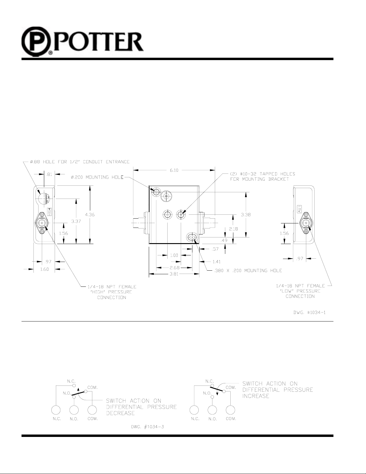
MOUNTING AND INSTALLATION
The Model DPS-50 may be mounted in any position on a flat surface by two screws or bolts through the
holes in back of the case, or by use of the universal mounting bracket in an area protected from the weather.
Locate switch where vibration, shock and ambient temperature fluctuations are mimimal. Be sure to connect
the high pressure source to the port labeled “HIGH” and the low pressure source to the port labeled “LOW”.
To avoid damage to the control, always hold a wrench on the wrench flats of the pressure ports when tightening pressure connections. Never tighten the pressure connections by turning the control into the fitting.
FIG. 1
WIRING
Use properly rated temperature supply wire for the anticipated service temperature.
Make all electrical connections in accordance with the National Electrical Code and local regulations.
Route wire under switch bracket to avoid interfering with switch actuation mechanism. (See Fig. 3)
FIG. 2
PRINTED IN USA PAGE 2 OF 4
MFG. #5401034 - REV B
6/97
Page 3

DPS-50
DIFFERENTIAL PRESSURE
SWITCH
ADJUSTMENTS
The differential pressure operating point of the switch can be adjusted to any point between 8 and 50 PSID
by using the “sight-set” calibrated scale and turning the adjustment knob to the left to raise the differential
pressure actuation point, and turning to the right to lower the differential actuation point. The scale is
calibrated for increasing differential pressure settings. The repeatability of the set operating pressure is
typically ±1% of the differential pressure range (±.5 PSI). The change in set operating pressure due to
change in ambient temperature is typically less than 1% (based on the differential pressure range) per
50°F. For best setting accuracy, make the final adjustment with a pressure gauge and the actual working
pressure encountered in the application.
FIG. 3
DIFFERENTIAL PRESSURE
SETTING ADJUSTMENT. TURN
KNOB TO THE LEFT TO RAISE
THE DIFFERENTIAL PRESSURE
ACTUATION POINT AND TURN
THE KNOB TO THE RIGHT TO
LOWER THE DIFFERENTIAL
PRESSURE ACTUATION POINT.
1/4 -18 NPT FEMALE
“LOW” PRESSURE
CONNECTION
1/4 -18 NPT FEMALE
“HIGH” PRESSURE
CONNECTION
ROUTE WIRE UNDER SWITCH
BRACKET TO AVOID INTERFERING WITH SWITCH ACTUATION
MECHANISM
SNAP-ACTION SPDT SWITCH
GROUND SCREW
.88 DIA HOLE FOR 1/2" CONDUIT
CONNECTION
)DISP(EGNARLAITNEREFFIDELBATSUJDA
GNISAERCED
ERUSSERPLAITNEREFFID
.NIM.XAM.NIM.XAM
6448056-2
PRINTED IN USA PAGE 3 OF 4
MFG. #5401034 - REV B
GNISAERCNI
ERUSSERPLAITNEREFFID
6/97
)ISP(DNABDAEDLACIPYT
)TESEROTEGNAHCLAITNEREFFID(
Page 4

DPS-50
DIFFERENTIAL PRESSURE
SWITCH
Potter Model DPS-50 Monitors Condition Of Pipeline Liquid Filter
In a typical liquid filter installation, a clean filter element will have a rated pressure drop for a given operating line
pressure and rate of flow. As the filter accumulates particulate, the resistance to flow increases and the pressure drop
increases until the level is reached when the filter element must be cleaned or replaced. Differential pressure switch
Model DPS-50 senses the differential pressure increase and actuates an alarm or signal light.
LOW
DPS-50
HIGH
DIRECTION OF FLOW
FILTER
Proof Of Flow Application In A Water Chiller System
On a proof of flow application in a water chiller system, if ice builds up inside water chiller, or if tubes become restricted, differential pressure across chiller increases. Differential pressure switch Model DPS-50 senses the differential
pressure increase and actuates an alarm or signal light.
DPS-50
OUTLET EXHUAST
WATER CONNECTED
TO LOW PRESSURE
CONNECTION OF
INLET SUPPLY
WATER CONNECTED
TO HIGH PRESSURE
CONNECTION OF
THE DPS-50
CHILLER
THE DPS-50
PRINTED IN USA PAGE 4 OF 4
MFG. #5401034 - REV B
6/97
 Loading...