

Page 1
CompactNSX
DOCA0140EN-01 01/2020
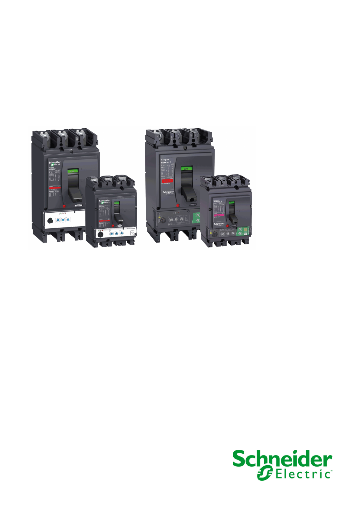
Compact NSX
Circuit Breakers and Switch-Disconnectors 100630 A
User Guide
01/2020
DOCA0140EN-01
www.se.com
Page 2

The information provided in this documentation contains general descriptions and/or technical character
istics of the performance of the products contained herein. This documentation is not intended as a
substitute for and is not to be used for determining suitability or reliability of these products for specific user
applications. It is the duty of any such user or integrator to perform the appropriate and complete risk
analysis, evaluation and testing of the products with respect to the relevant specific application or use
thereof. Neither Schneider Electric nor any of its affiliates or subsidiaries shall be responsible or liable for
misuse of the information contained herein. If you have any suggestions for improvements or amendments
or have found errors in this publication, please notify us.
You agree not to reproduce, other than for your own personal, noncommercial use, all or part of this
document on any medium whatsoever without permission of Schneider Electric, given in writing. You also
agree not to establish any hypertext links to this document or its content. Schneider Electric does not grant
any right or license for the personal and noncommercial use of the document or its content, except for a
non-exclusive license to consult it on an "as is" basis, at your own risk. All other rights are reserved.
All pertinent state, regional, and local safety regulations must be observed when installing and using this
product. For reasons of safety and to help ensure compliance with documented system data, only the
manufacturer should perform repairs to components.
When devices are used for applications with technical safety requirements, the relevant instructions must
be followed.
Failure to use Schneider Electric software or approved software with our hardware products may result in
injury, harm, or improper operating results.
Failure to observe this information can result in injury or equipment damage.
© 2020 Schneider Electric. All rights reserved.
-
2 DOCA0140EN-01 01/2020
Page 3

Table of Contents
Safety Information. . . . . . . . . . . . . . . . . . . . . . . . . . . . . . . . . . . . . . . . . . . . 5
About the Book . . . . . . . . . . . . . . . . . . . . . . . . . . . . . . . . . . . . . . . . . . . . . . 7
Chapter 1 Compact NSX Circuit Breakers . . . . . . . . . . . . . . . . . . . . . . . . . . . . . . . . . 9
1.1 Compact NSX Circuit Breaker Presentation . . . . . . . . . . . . . . . . . . . . . . . . . . . . . . . . . . . . .
Compact NSX Range . . . . . . . . . . . . . . . . . . . . . . . . . . . . . . . . . . . . . . . . . . . . . . . . . . . . . .
Operating the Circuit Breaker . . . . . . . . . . . . . . . . . . . . . . . . . . . . . . . . . . . . . . . . . . . . . . . .
EcoStruxure Power Commission Software . . . . . . . . . . . . . . . . . . . . . . . . . . . . . . . . . . . . . .
De-Energizing the Circuit Breaker . . . . . . . . . . . . . . . . . . . . . . . . . . . . . . . . . . . . . . . . . . . . .
Environmental Conditions . . . . . . . . . . . . . . . . . . . . . . . . . . . . . . . . . . . . . . . . . . . . . . . . . . .
1.2 Circuit Breaker With Toggle Handle . . . . . . . . . . . . . . . . . . . . . . . . . . . . . . . . . . . . . . . . . . .
Front Face Description . . . . . . . . . . . . . . . . . . . . . . . . . . . . . . . . . . . . . . . . . . . . . . . . . . . . .
Opening, Closing, and Resetting the Circuit Breaker . . . . . . . . . . . . . . . . . . . . . . . . . . . . . .
Testing the Circuit Breaker . . . . . . . . . . . . . . . . . . . . . . . . . . . . . . . . . . . . . . . . . . . . . . . . . .
Locking the Circuit Breaker . . . . . . . . . . . . . . . . . . . . . . . . . . . . . . . . . . . . . . . . . . . . . . . . . .
1.3 Circuit Breaker With Rotary Handle. . . . . . . . . . . . . . . . . . . . . . . . . . . . . . . . . . . . . . . . . . . .
Front Face Description . . . . . . . . . . . . . . . . . . . . . . . . . . . . . . . . . . . . . . . . . . . . . . . . . . . . .
Opening, Closing, and Resetting the Circuit Breaker . . . . . . . . . . . . . . . . . . . . . . . . . . . . . .
Testing a Circuit Breaker With Direct Rotary Handle . . . . . . . . . . . . . . . . . . . . . . . . . . . . . .
Locking a Circuit Breaker With Direct Rotary Handle . . . . . . . . . . . . . . . . . . . . . . . . . . . . . .
Testing a Circuit Breaker With Extended Rotary Handle. . . . . . . . . . . . . . . . . . . . . . . . . . . .
Locking a Circuit Breaker With Extended Rotary Handle . . . . . . . . . . . . . . . . . . . . . . . . . . .
1.4 Motor-Operated Circuit Breakers. . . . . . . . . . . . . . . . . . . . . . . . . . . . . . . . . . . . . . . . . . . . . .
Front Face Description . . . . . . . . . . . . . . . . . . . . . . . . . . . . . . . . . . . . . . . . . . . . . . . . . . . . .
Opening, Closing, and Resetting a Circuit Breaker With Motor Mechanism . . . . . . . . . . . . .
Opening, Closing, and Resetting Circuit Breakers With Communicating Motor Mechanism.
Locking the Circuit Breaker . . . . . . . . . . . . . . . . . . . . . . . . . . . . . . . . . . . . . . . . . . . . . . . . . .
Chapter 2 Compact NSX Installation Accessories . . . . . . . . . . . . . . . . . . . . . . . . . . . 53
Plug-in Circuit Breaker. . . . . . . . . . . . . . . . . . . . . . . . . . . . . . . . . . . . . . . . . . . . . . . . . . . . . .
Withdrawable Circuit Breaker . . . . . . . . . . . . . . . . . . . . . . . . . . . . . . . . . . . . . . . . . . . . . . . .
Accessories . . . . . . . . . . . . . . . . . . . . . . . . . . . . . . . . . . . . . . . . . . . . . . . . . . . . . . . . . . . . . .
Chapter 3 Compact NSX Electrical Auxiliary Devices . . . . . . . . . . . . . . . . . . . . . . . . . 65
Electrical Auxiliary Device Summary . . . . . . . . . . . . . . . . . . . . . . . . . . . . . . . . . . . . . . . . . . .
Indication Contacts . . . . . . . . . . . . . . . . . . . . . . . . . . . . . . . . . . . . . . . . . . . . . . . . . . . . . . . .
SDx Module . . . . . . . . . . . . . . . . . . . . . . . . . . . . . . . . . . . . . . . . . . . . . . . . . . . . . . . . . . . . . .
SDTAM Module (Micrologic 2 M and 6 E-M). . . . . . . . . . . . . . . . . . . . . . . . . . . . . . . . . . . . .
BSCM Breaker Status Control Module . . . . . . . . . . . . . . . . . . . . . . . . . . . . . . . . . . . . . . . . .
NSX Cord . . . . . . . . . . . . . . . . . . . . . . . . . . . . . . . . . . . . . . . . . . . . . . . . . . . . . . . . . . . . . . .
Insulated NSX Cord. . . . . . . . . . . . . . . . . . . . . . . . . . . . . . . . . . . . . . . . . . . . . . . . . . . . . . . .
Control Auxiliaries . . . . . . . . . . . . . . . . . . . . . . . . . . . . . . . . . . . . . . . . . . . . . . . . . . . . . . . . .
Chapter 4 Compact NSX Trip Units. . . . . . . . . . . . . . . . . . . . . . . . . . . . . . . . . . . . . . . 85
4.1 Fault Currents and Trip Units . . . . . . . . . . . . . . . . . . . . . . . . . . . . . . . . . . . . . . . . . . . . . . . .
Applications . . . . . . . . . . . . . . . . . . . . . . . . . . . . . . . . . . . . . . . . . . . . . . . . . . . . . . . . . . . . . .
Fault Currents in Electrical Distribution . . . . . . . . . . . . . . . . . . . . . . . . . . . . . . . . . . . . . . . . .
Protection Against Overcurrents in Electrical Distribution . . . . . . . . . . . . . . . . . . . . . . . . . . .
Protection Against Ground Faults . . . . . . . . . . . . . . . . . . . . . . . . . . . . . . . . . . . . . . . . . . . . .
Protection for Motor-Feeders. . . . . . . . . . . . . . . . . . . . . . . . . . . . . . . . . . . . . . . . . . . . . . . . .
10
11
17
19
20
22
24
25
26
28
29
31
32
34
36
37
40
42
44
45
47
50
51
54
58
64
66
70
71
74
76
79
81
83
86
87
88
89
91
93
DOCA0140EN-01 01/2020 3
Page 4

4.2 TM-D, TM-G Thermal-Magnetic and MA Magnetic Trip Units . . . . . . . . . . . . . . . . . . . . . . . .
Thermal-Magnetic Trip Unit Summary . . . . . . . . . . . . . . . . . . . . . . . . . . . . . . . . . . . . . . . . . .
TM-D Thermal-Magnetic Trip Unit for 1P and 2P Circuit Breakers . . . . . . . . . . . . . . . . . . . .
TM-D Thermal-Magnetic Trip Unit for 3P and 4P Circuit Breakers up to 63 A. . . . . . . . . . . .
TM-D Thermal-Magnetic Trip Unit for 3P and 4P Circuit Breakers from 80 A to 250 A . . . .
TM-G Thermal-Magnetic Trip Unit . . . . . . . . . . . . . . . . . . . . . . . . . . . . . . . . . . . . . . . . . . . .
MA Magnetic Trip Unit . . . . . . . . . . . . . . . . . . . . . . . . . . . . . . . . . . . . . . . . . . . . . . . . . . . . . .
4.3 Vigi Earth-Leakage Protection Module. . . . . . . . . . . . . . . . . . . . . . . . . . . . . . . . . . . . . . . . . .
Vigi Earth-Leakage Protection Module. . . . . . . . . . . . . . . . . . . . . . . . . . . . . . . . . . . . . . . . . .
4.4 Micrologic Electronic Trip Units . . . . . . . . . . . . . . . . . . . . . . . . . . . . . . . . . . . . . . . . . . . . . . .
Characteristics of Micrologic Electronic Trip Units . . . . . . . . . . . . . . . . . . . . . . . . . . . . . . . . .
Micrologic 2 Electronic Trip Units. . . . . . . . . . . . . . . . . . . . . . . . . . . . . . . . . . . . . . . . . . . . . .
Micrologic 4 Electronic Trip Units. . . . . . . . . . . . . . . . . . . . . . . . . . . . . . . . . . . . . . . . . . . . . .
Micrologic 1.3 M Electronic Trip Unit . . . . . . . . . . . . . . . . . . . . . . . . . . . . . . . . . . . . . . . . . . .
Micrologic 2 M Electronic Trip Unit. . . . . . . . . . . . . . . . . . . . . . . . . . . . . . . . . . . . . . . . . . . . .
Micrologic 2 G Electronic Trip Unit. . . . . . . . . . . . . . . . . . . . . . . . . . . . . . . . . . . . . . . . . . . . .
Micrologic 2 AB and 4 AB Electronic Trip Units . . . . . . . . . . . . . . . . . . . . . . . . . . . . . . . . . .
Chapter 5 Maintenance Interfaces for Micrologic Trip Units . . . . . . . . . . . . . . . . . . . . . 137
Micrologic Maintenance Interfaces. . . . . . . . . . . . . . . . . . . . . . . . . . . . . . . . . . . . . . . . . . . . .
Pocket Battery . . . . . . . . . . . . . . . . . . . . . . . . . . . . . . . . . . . . . . . . . . . . . . . . . . . . . . . . . . . .
Stand-Alone USB Maintenance Interface . . . . . . . . . . . . . . . . . . . . . . . . . . . . . . . . . . . . . . .
USB Maintenance Interface Connected to a PC . . . . . . . . . . . . . . . . . . . . . . . . . . . . . . . . . .
Chapter 6 Compact NSX Circuit Breakers Operation . . . . . . . . . . . . . . . . . . . . . . . . . 147
Commissioning. . . . . . . . . . . . . . . . . . . . . . . . . . . . . . . . . . . . . . . . . . . . . . . . . . . . . . . . . . . .
Maintaining the Circuit Breaker During Operation . . . . . . . . . . . . . . . . . . . . . . . . . . . . . . . . .
Responding to a Trip . . . . . . . . . . . . . . . . . . . . . . . . . . . . . . . . . . . . . . . . . . . . . . . . . . . . . . .
Troubleshooting . . . . . . . . . . . . . . . . . . . . . . . . . . . . . . . . . . . . . . . . . . . . . . . . . . . . . . . . . . .
Appendices . . . . . . . . . . . . . . . . . . . . . . . . . . . . . . . . . . . . . . . . . . . . . . . . . . . . . .
Appendix A Wiring Diagrams. . . . . . . . . . . . . . . . . . . . . . . . . . . . . . . . . . . . . . . . . . . . . . 161
Fixed Circuit Breakers . . . . . . . . . . . . . . . . . . . . . . . . . . . . . . . . . . . . . . . . . . . . . . . . . . . . . .
Plug-in / Withdrawable Circuit Breakers. . . . . . . . . . . . . . . . . . . . . . . . . . . . . . . . . . . . . . . . .
Motor Mechanism. . . . . . . . . . . . . . . . . . . . . . . . . . . . . . . . . . . . . . . . . . . . . . . . . . . . . . . . . .
SDx Module With Micrologic 2, 4, 5, 6, and 7 Trip Unit . . . . . . . . . . . . . . . . . . . . . . . . . . . . .
SDTAM Module With Micrologic M . . . . . . . . . . . . . . . . . . . . . . . . . . . . . . . . . . . . . . . . . . . .
Appendix B Additional Characteristics. . . . . . . . . . . . . . . . . . . . . . . . . . . . . . . . . . . . . . . 177
Compact NSX100-250 - Distribution Protection. . . . . . . . . . . . . . . . . . . . . . . . . . . . . . . . . . .
Compact NSX100-250 - Motor-Feeder Protection . . . . . . . . . . . . . . . . . . . . . . . . . . . . . . . . .
Compact NSX400-630 - Distribution Protection. . . . . . . . . . . . . . . . . . . . . . . . . . . . . . . . . . .
Compact NSX400-630 - Motor-Feeder Protection . . . . . . . . . . . . . . . . . . . . . . . . . . . . . . . . .
Compact NSX100-630 - Reflex Tripping . . . . . . . . . . . . . . . . . . . . . . . . . . . . . . . . . . . . . . . .
Compact NSX100-630 - Limitation Curves . . . . . . . . . . . . . . . . . . . . . . . . . . . . . . . . . . . . . .
Index . . . . . . . . . . . . . . . . . . . . . . . . . . . . . . . . . . . . . . . . . . . . . . . . . . . . . .
96
97
99
100
101
104
106
108
108
111
112
118
122
127
129
132
134
138
139
141
144
148
153
155
157
159
162
165
170
172
174
178
184
185
186
187
188
191
4 DOCA0140EN-01 01/2020
Page 5
Safety Information
Important Information
NOTICE
Read these instructions carefully, and look at the equipment to become familiar with the device before
trying to install, operate, service, or maintain it. The following special messages may appear throughout
this documentation or on the equipment to warn of potential hazards or to call attention to information that
clarifies or simplifies a procedure.
PLEASE NOTE
Electrical equipment should be installed, operated, serviced, and maintained only by qualified personnel.
No responsibility is assumed by Schneider Electric for any consequences arising out of the use of this
material.
A qualified person is one who has skills and knowledge related to the construction and operation of
electrical equipment and its installation, and has received safety training to recognize and avoid the
hazards involved.
DOCA0140EN-01 01/2020 5
Page 6

CYBERSECURITY SAFETY NOTICE
POTENTIAL COMPROMISE OF SYSTEM AVAILABILITY, INTEGRITY, AND CONFIDENTIALITY
Change default passwords at first use to help prevent unauthorized access to device settings,
controls, and information.
Disable unused ports/services and default accounts to help minimize pathways for malicious
attackers.
Place networked devices behind multiple layers of cyber defenses (such as firewalls, network
segmentation, and network intrusion detection and protection).
Use cybersecurity best practices (for example, least privilege, separation of duties) to help prevent
unauthorized exposure, loss, modification of data and logs, or interruption of services.
Failure to follow these instructions can result in death, serious injury, or equipment damage.
WARNING
6 DOCA0140EN-01 01/2020
Page 7
At a Glance
Document Scope
Validity Note
Related Documents
About the Book
The aim of this guide is to provide users, installers and maintenance personnel with the technical
information needed to operate Compact NSX circuit breakers and switch-disconnectors in compliance with
the IEC/EN standards.
This guide applies to Compact NSX circuit breakers and switch-disconnectors.
The information contained in this guide is likely to be updated at any time. Schneider Electric strongly
recommends that you have the most recent and up-to-date version available on
electric.com
Title of Documentation Reference Number
Compact NSX & NSXm Catalogue LVPED217032EN
Compact NSX Micrologic 5/6/7 Electronic Trip Units - User Guide DOCA0141EN
Compact NSX - Modbus Communication Guide DOCA0091EN
Enerlin'X IO - Input/Output Application Module for One IEC Circuit
Breaker - User Guide
Enerlin'X IFE - Ethernet Interface for One IEC Circuit Breaker - User
Guide
ULP System (IEC Standard) - User Guide DOCA0093EN
.
DOCA0141ES
DOCA0141FR
DOCA0141ZH
DOCA0091ES
DOCA0091FR
DOCA0091ZH
DOCA0055EN
DOCA0055ES
DOCA0055FR
DOCA0055ZH
DOCA0084EN
DOCA0084ES
DOCA0084FR
DOCA0084ZH
DOCA0093ES
DOCA0093FR
DOCA0093ZH
www.schneider-
You can download these technical publications and other technical information from our website at
https://www.se.com/ww/en/download/ .
Trademark Notice
All trademarks are owned by Schneider Electric Industries SAS or its affiliated companies.
DOCA0140EN-01 01/2020 7
Page 8

8 DOCA0140EN-01 01/2020
Page 9

CompactNSX
Compact NSX Circuit Breakers
DOCA0140EN-01 01/2020
Compact NSX Circuit Break ers
Chapter 1
Compact NSX Circuit Breakers
What Is in This Chapter?
This chapter contains the following sections:
Section Topic Page
1.1 Compact NSX Circuit Breaker Presentation 10
1.2 Circuit Breaker With Toggle Handle 24
1.3 Circuit Breaker With Rotary Handle 31
1.4 Motor-Operated Circuit Breakers 44
DOCA0140EN-01 01/2020 9
Page 10

Compact NSX Circuit Breakers
CompactNSX Circuit Breaker Presentation
Section 1.1
Compact NSX Circuit Breaker Presentation
What Is in This Section?
This section contains the following topics:
Compact NSX Range 11
Operating the Circuit Breaker 17
EcoStruxure Power Commission Software 19
De-Energizing the Circuit Breaker 20
Environmental Conditions 22
Topic Page
10
DOCA0140EN-01 01/2020
Page 11

Compact NSX Range
Description
The Compact NSX alternating current (AC) range consists of
Circuit breakers and switch-disconnectors operating on alternating current:
1-pole circuit breakers from 16 to 250 A, up to 240 Vac
2-pole circuit breakers from 16 to 160 A, up to 690 Vac
3 and 4-pole circuit breakers and switch-disconnectors from 16 to 630 A, up to 690 Vac
A set of standard accessories and auxiliaries shared with the Compact NSX DC range
The Compact NSX range covers the following applications:
Electrical distribution protection
Special protection for receivers (for example, motors, transformers) or generators
The Compact NSX range is compliant with the following standards:
IEC/EN 60947-2 for circuit breakers
IEC/EN 60947-3 for switch-disconnectors
IEC/EN 60947-2 and IEC/EN 60947-4-1 for motor protection circuit breakers
UL 60947-4-1 for motor protection circuit breakers
CSA-C22.2 No.60947-4-1-14 for motor protection circuit breakers
Convention
In this guide, the term
circuit breaker
Compact NSX Circuit Breakers
covers circuit breakers and switch-disconnectors.
DOCA0140EN-01 01/2020 11
Page 12
Compact NSX Circuit Breakers
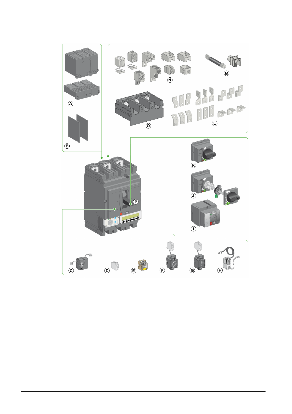
Fixed Circuit Breaker
12
A Sealable terminal shields
B Interphase barriers
C BSCM module
D Indication contact
E Voltage release
F SDTAM module
G SDx module
H NSX cord
I Motor mechanism
J Extended rotary handle
K Direct rotary handle
L Terminal extensions
M Rear connectors
N Cable connectors
O One-piece spreader
P Toggle handle
DOCA0140EN-01 01/2020
Page 13
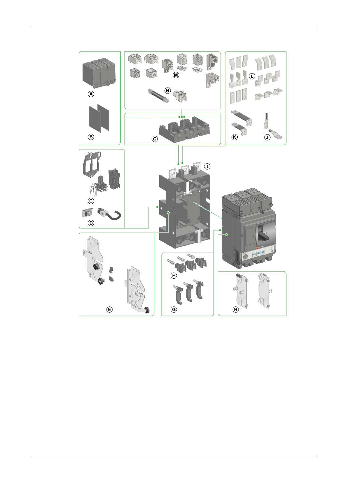
Withdrawable or Plug-in Circuit Breaker
Compact NSX Circuit Breakers
A Sealable long terminal shields for plug-in base
B Interphase barriers
C Automatic withdrawable auxiliary connector
D Manual auxiliary connector
E Chassis side plate for withdrawable circuit breaker
F Power connections
G Power connections for circuit breaker with Vigi module
H Circuit-breaker side plate
I Circuit-breaker plug-in base
J Lugs
K Rear connectors
L Terminal extensions
M Cable connectors
N Rear connectors
O Adapter
DOCA0140EN-01 01/2020 13
Page 14
Compact NSX Circuit Breakers
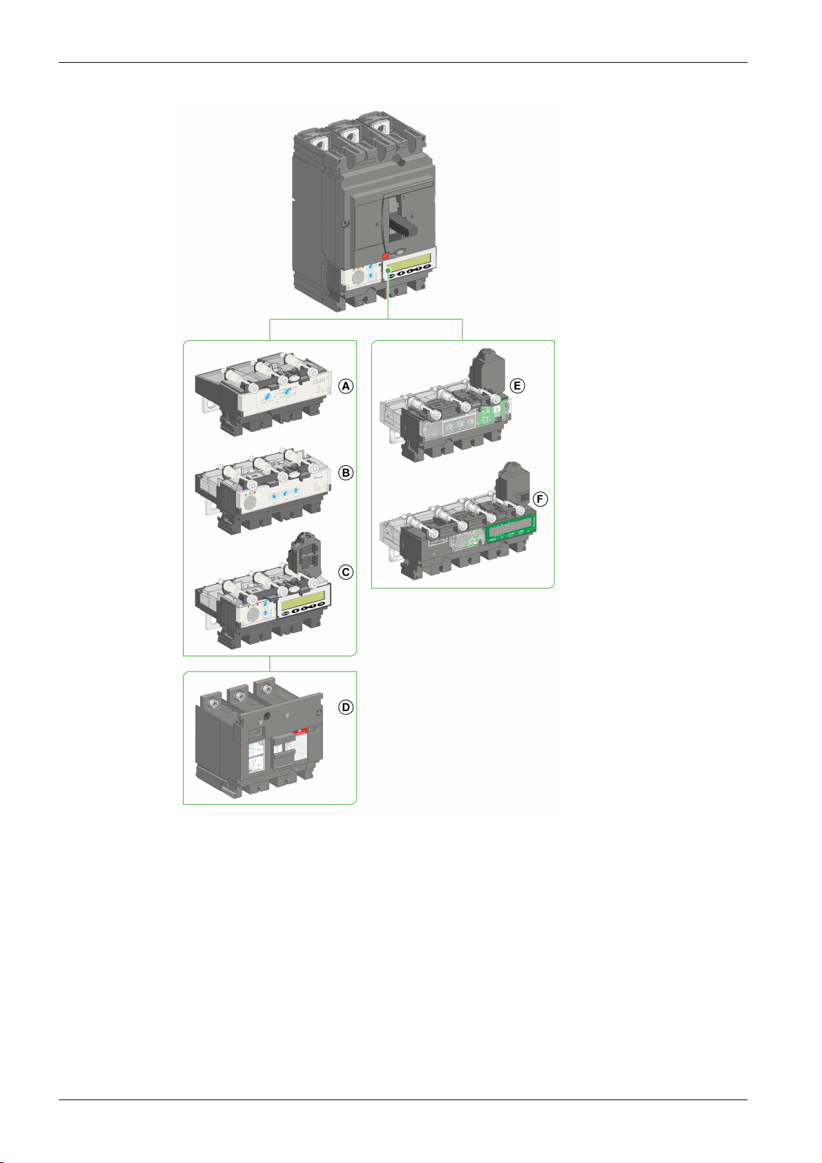
Trip Units and Trip Unit Accessories
14
A TM-D, TM-G, or MA trip unit
B Micrologic 1 or 2 trip unit
C Micrologic 5 or 6 trip unit
D Vigi module for additional earth-leakage
protection
E Micrologic 4 trip unit with earth-leakage
protection
F Micrologic 7 trip unit with earth-leakage
protection
DOCA0140EN-01 01/2020
Page 15
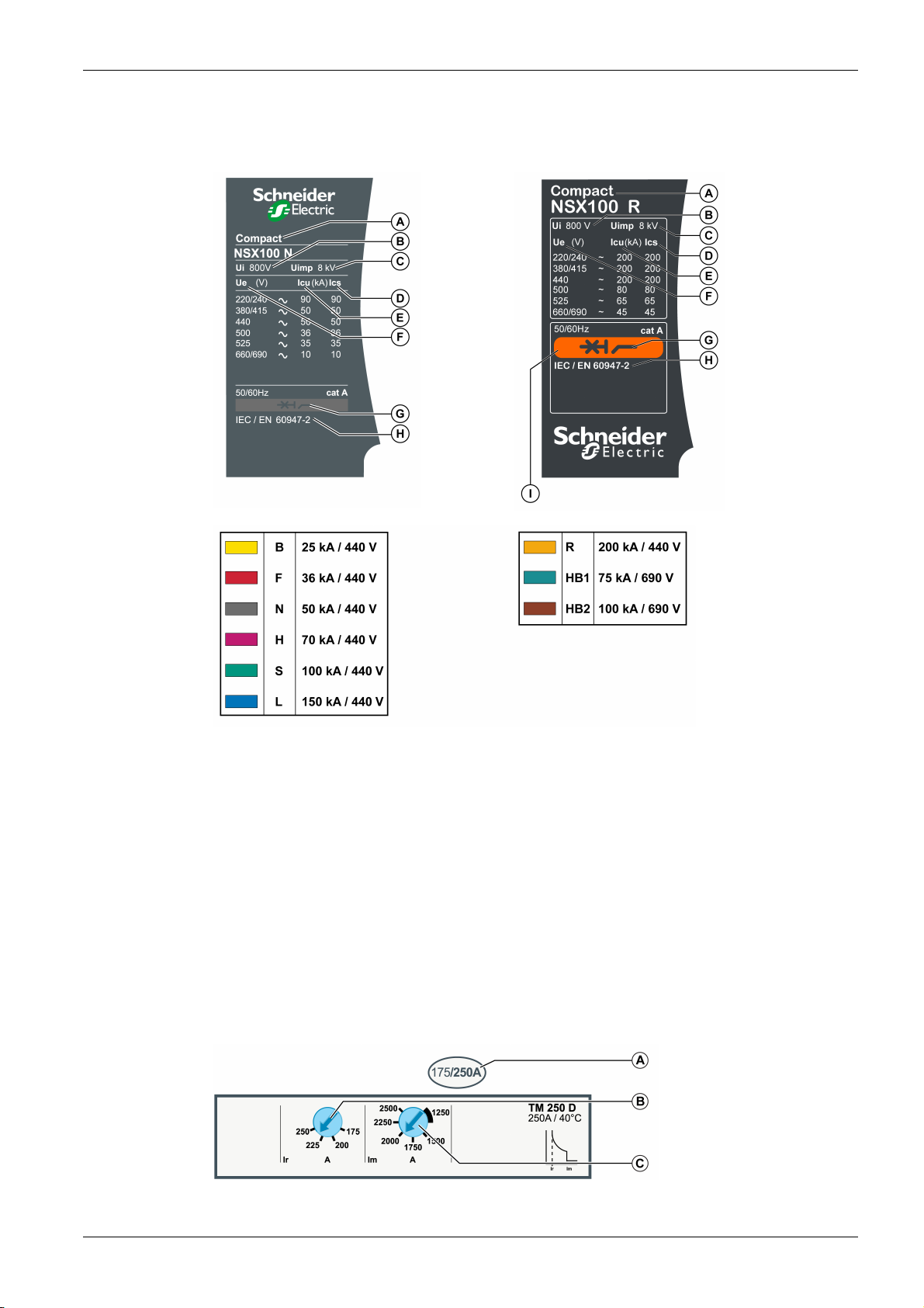
Identification
Compact NSX Circuit Breakers
The faceplate on the front of the circuit breaker identifies the circuit breaker and its characteristics.
The faceplate depends on the breaking performances:
Dial Settings
A Device size and rated current
B Ui: rated insulation voltage
C Uimp: rated impulse withstand voltage
D Ics: rated service short-circuit breaking capacity
E Icu: rated ultimate short-circuit breaking capacity
F Ue: rated operational voltage
G Type of device: circuit breaker or switch-disconnector, suitable for isolation
H Standards
I Color code indicating breaking performance
NOTE: R, HB1, and HB2 breaking performances are not compatible with Micrologic 4 and 7 trip units.
NOTE: For extended rotary handles, open the door to view the faceplate label.
The dial positions on the front of the trip unit set the circuit breaker pickup settings.
Example 1: TM-D thermal-magnetic trip unit
A Setting range for TM-D
thermal-magnetic trip unit
B Adjustment dial for the
thermal protection pickup Ir
C Adjustment dial for the
magnetic protection pickup
Im (for TM-D 200/250 only)
DOCA0140EN-01 01/2020 15
Page 16
Compact NSX Circuit Breakers
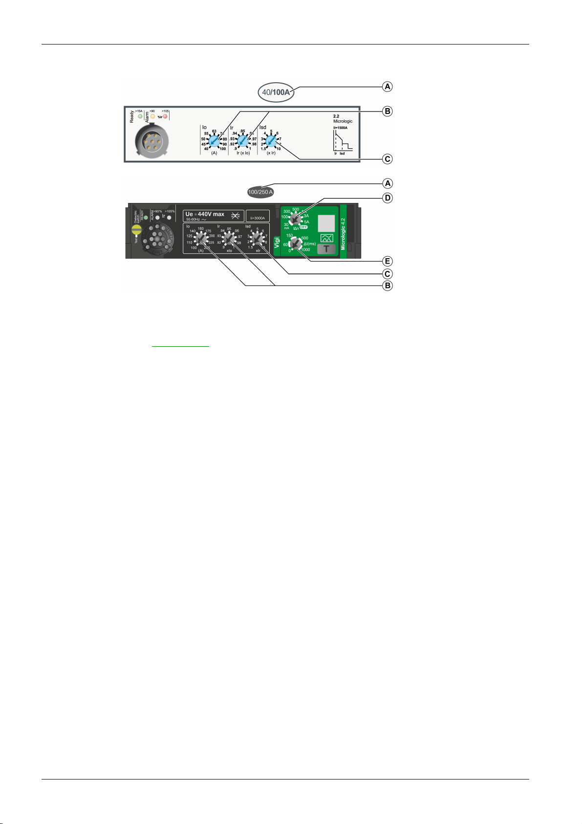
Example 2: Micrologic 2 and Micrologic 4 electronic trip units
Trip Unit Settings
For Micrologic 5, 6, and 7 electronic trip units, read all settings on the display unit. For more information,
refer to
A Trip unit adjustment range
B Adjustment dials for the
long-time protection pickup
Io and Ir
C Adjustment dial for the
short-time protection pickup
Isd
D Adjustment dial for the
earth-leakage current
pickup IΔn
E Adjustment dial for the
earth-leakage time delay Δt
DOCA0141EN, Compact NSX Micrologic 5/6/7 Electronic Trip Units - User Guide
.
16
DOCA0140EN-01 01/2020
Page 17
Compact NSX Circuit Breakers
Operating the Circuit Breaker
Circuit Breaker Operating Control Accessories
The following table shows the operating control accessories compatible with the Compact NSX circuit
breakers. For more information, refer to
Operating control accessory NSX100 NSX160 NSX250 NSX400 NSX630
1P 2P 3P/4P 1P 2P 3P/4P 1P 2P 3P/4P 3P/4P 3P/4P
Toggle handle ✔ ✔ ✔ ✔ ✔ ✔ ✔ – ✔ ✔ ✔
Rotary handle – – ✔ – – ✔ – – ✔ ✔ ✔
Motor mechanism – – ✔ – – ✔ – – ✔ ✔ ✔
Communicating motor
mechanism
––✔ ––✔ ––✔ ✔ ✔
Handle Position
The handle position indicates the state of the circuit breaker:
Toggle handle Rotary handle Motor mechanism
Compact NSX & NSXm Catalogue
.
I (ON): Circuit breaker closed.
Closed manually.
O (OFF): Circuit breaker open.
Opened manually.
Trip or Tripped: Circuit breaker tripped.
Tripped by the protection (trip unit or trip auxiliaries), the push-to-trip button, or the
USB maintenance interface.
Load Indication
Circuit breakers equipped with a Micrologic trip unit provide precise information of the state of the circuit
breaker or the installation. This information can be used for the management and maintenance of the
installation.
For example, if the pre-alarm or alarm indicator is lit, performing load shedding may prevent tripping due
to circuit breaker overload.
A The Ready LED (green) blinks slowly when the electronic trip unit is ready to provide protection.
B The overload pre-alarm LED (orange) shows a steady light when the load exceeds 90% of the Ir setting.
C The overload alarm LED (red) shows a steady light when the load exceeds 105% of the Ir setting.
I (ON): Circuit breaker closed (in Auto or Manu
mode).
O (OFF): Circuit breaker open or tripped (in
Auto or Manu mode).
Remote Indication
Information is available remotely:
From the indication contacts
By using a communication network
These indication auxiliaries can be installed on site.
For more information about the remote indication and communication options, refer to the summary tables
of auxiliaries
User Guide
DOCA0140EN-01 01/2020 17
(see page 66)
.
and to
DOCA0141EN, Compact NSX Micrologic 5/6/7 Electronic Trip Units -
Page 18
Compact NSX Circuit Breakers
Remote Electrical Stop Command
The remote electrical stop command can be given by electrical control auxiliaries regardless of the control
type in use.
To obtain a remote electrical stop command, use:
An MX shunt trip release, or
An MN undervoltage trip release, or
An MN undervoltage trip release with time-delay unit (the time-delay unit overcomes the problem of
micro-cuts).
For more information about the electrical control auxiliaries, refer to the relevant topic
NOTE: It is advisable to test operation of the remote electrical stop commands at regular intervals (every
six months).
(seepage83)
.
18
DOCA0140EN-01 01/2020
Page 19

Compact NSX Circuit Breakers
EcoStruxure Power Commission Software
Overview
EcoStruxure
EcoStruxure Power Commission software helps you to manage a project as part of testing, commissioning,
and maintenance phases of the project life cycle. The innovative features in it provide simple ways to
configure, test, and commission the smart electrical devices.
EcoStruxure Power Commission software automatically discovers the smart devices and allows you to add
the devices for an easy configuration. You can generate comprehensive reports as part of Factory
Acceptance Test and Site Acceptance Test to replace your heavy manual work. Additionally, when the
panels are under operation, any change of settings made can be easily identified by a yellow highlighter.
This indicates the difference between the project and device values, and hence provides a system
consistency during the operation and maintenance phase.
EcoStruxure Power Commission software enables the configuration of the following circuit breakers,
modules, and accessories:
Circuit breaker ranges Modules Accessories
Masterpact MTZ circuit breakers
Masterpact NT/NW circuit breakers
Compact NS circuit breakers
PowerPact P- and R-frame circuit breakers
Compact NSX circuit breakers
PowerPact H-, J- and L-frame circuit
breakers
(1) For FDM121 display, only the firmware and language download are supported.
TM
Power Commission is the new name of Ecoreach software.
Micrologic X control unit
Communication interface modules: IFM
interface, IFE interface, IFE server, and EIFE
interface
ULP modules: IO module
Micrologic trip units
Communication interface modules: BCM
module, CCM module, BCM ULP module, IFM
interface, IFE interface, IFE server
ULP modules: IO module, FDM121 display
Micrologic trip units
Communication interface modules: BSCM
(1)
module, IFM interface, IFE interface, IFE server
ULP modules: IO module, FDM121 display
(1)
M2C output module
M2C and M6C output modules
SDTAM and SDx output modules
Key Features
For more information, refer to the
EcoStruxure Power Commission Online Help
EcoStruxure Power Commission software is available at
www.se.com
.
EcoStruxure Power Commission software performs the following actions for the supported devices and
modules:
Create projects by device discovery
Save the project in the EcoStruxure Power Commission cloud for reference
Upload settings to the device and download settings from the device
Compare the settings between the project and the device
Perform control actions in a secured way
Generate and print the device settings report
Perform a communication wiring test on the entire project and generate and print test report
View the communication architecture between the devices in a graphical representation
View the measurements, logs, and maintenance information
Export Waveform Capture on Trip Event (WFC)
View the status of device and IO module
View the alarm details
Buy, install, remove, or retrieve the Digital Modules
Check the system firmware compatibility status
Update to the latest device firmware
Perform force trip and automatic trip curve tests
DOCA0140EN-01 01/2020 19
Page 20
Compact NSX Circuit Breakers
De-Energizing the Circuit Breaker
Isolation Capacity
Compact NSX circuit breakers offer positive contact indication and are suitable for isolation in accordance
with standards IEC/EN 60947-1 and 2. The O (OFF) position of the actuator is sufficient to isolate the
circuit breaker concerned.
The following marking on the faceplate label indicates that the circuit breaker is capable of isolation:
To confirm this capability, standards IEC/EN 60947-1 and 2 require specific shock withstand tests.
Compact NSX circuit breakers can be locked in the O (OFF) position to allow work to be carried out with
the power off in accordance with installation rules. The circuit breaker can only be locked in the open
position if the circuit breaker is in the O (OFF) position.
NOTE: Locking a Compact NSX circuit breaker in the open position is sufficient to isolate the circuit
breaker.
The locks depend on the type of actuator:
For circuit breakers with toggle handles, refer to the locking accessories
For circuit breakers with rotary handles, refer to how to lock the circuit breaker with direct rotary handle
(see page 37)
For circuit breakers with motor mechanisms, refer to how to lock the circuit breaker
Maintenance and Servicing Work on Installation
and how to lock the circuit breaker with extended rotary handle
(see page 29)
(see page 42)
(see page 51)
.
.
.
HAZARD OF ELECTRIC SHOCK, EXPLOSION, OR ARC FLASH
Apply appropriate personal protective equipment (PPE) and follow safe electrical work practices. See
NFPA 70E or CSA Z462 or local equivalent.
This equipment must only be installed and serviced by qualified electrical personnel.
Turn off all power supplying this equipment before working on or inside equipment.
Always use a properly rated voltage sensing device to confirm that power is off.
Replace all devices, doors, and covers before turning on power to this equipment.
Repair the installation immediately if an insulation fault occurs during operation.
Failure to follow these instructions will result in death or serious injury.
Turn off all power supplying the equipment before working on or inside equipment. For a partial powering
down of the installation, the installation and safety rules require clearly labeling and isolating the feed being
worked on.
Maintenance Work Following Fault Trip
HAZARD OF CLOSING ON ELECTRICAL FAULT
Do not close the circuit breaker again without first inspecting and, if necessary, repairing the downstream
electrical equipment.
Failure to follow these instructions can result in death, serious injury, or equipment damage.
DANGER
WARNING
20
The fact that a protection has tripped does not remedy the cause of the fault detected on the downstream
electrical equipment.
The following table describes the procedure to be followed after a fault trip:
Step Action
1 Isolate the feed before inspecting the downstream electrical equipment.
2 Look for the cause of the detected fault.
3 Inspect and, if necessary, repair the downstream equipment.
4 Inspect the equipment in the event of a short-circuit trip.
5 Close the circuit breaker again.
DOCA0140EN-01 01/2020
Page 21
For more information about troubleshooting and restarting following a fault, refer to what to do in the event
of a trip
Checking the Settings
Checking settings does not require any particular precautions. The checks must be carried out by a
qualified person.
Testing the Circuit Breaker
HAZARD OF NUISANCE TRIPPING
Protection tests must be done by qualified electrical personnel.
Failure to follow these instructions can result in injury or equipment damage.
When testing circuit breaker trip mechanisms, precautions must be taken:
To avoid disrupting operations.
To avoid inappropriate actions or tripping of alarms.
For example, tripping the circuit breaker with the push-to-trip button or the LTU test software can lead to
inappropriate fault indications or corrective actions (such as switching to a replacement power source).
(see page 155)
Compact NSX Circuit Breakers
.
CAUTION
Setting the Trip Unit
WARNING
HAZARD OF NUISANCE TRIPPING OR FAILURE TO TRIP
Protection setting adjustments must be done by qualified electrical personnel.
Failure to follow these instructions can result in death, serious injury, or equipment damage.
Modifying trip unit settings requires a thorough knowledge of the installation and safety rules.
DOCA0140EN-01 01/2020 21
Page 22
Compact NSX Circuit Breakers
Environmental Conditions
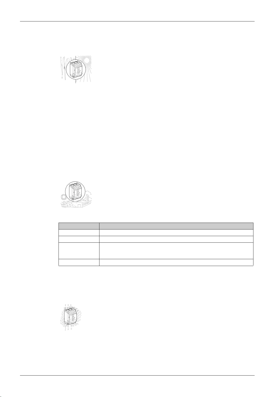
Ambient Temperature
The ambient temperature refers to the temperature of the air immediately surrounding the circuit breaker.
Operation temperature
–25 to +70 °C (–13 to +158 °F): Normal operating temperature
NOTE: The minimum operating temperature for the earth-leakage fault indicator on the Micrologic 4
trip unit is -15 °C (5°F). Between -15 and -5 °C (5 and 23 °F), and when operating the device with an
earth leakage fault and a very low load compared to the trip unit rating In, the earth leakage indicator
may not work correctly (fault indication or reset).
–35 to –25 °C (–31 to –13 °F): Commissioning possible
Storage temperature
–50 to +85 °C (–58 to +185 °F): Without Micrologic trip unit
–40 to +85 °C (–40 to +185 °F): With liquid crystal Micrologic trip unit
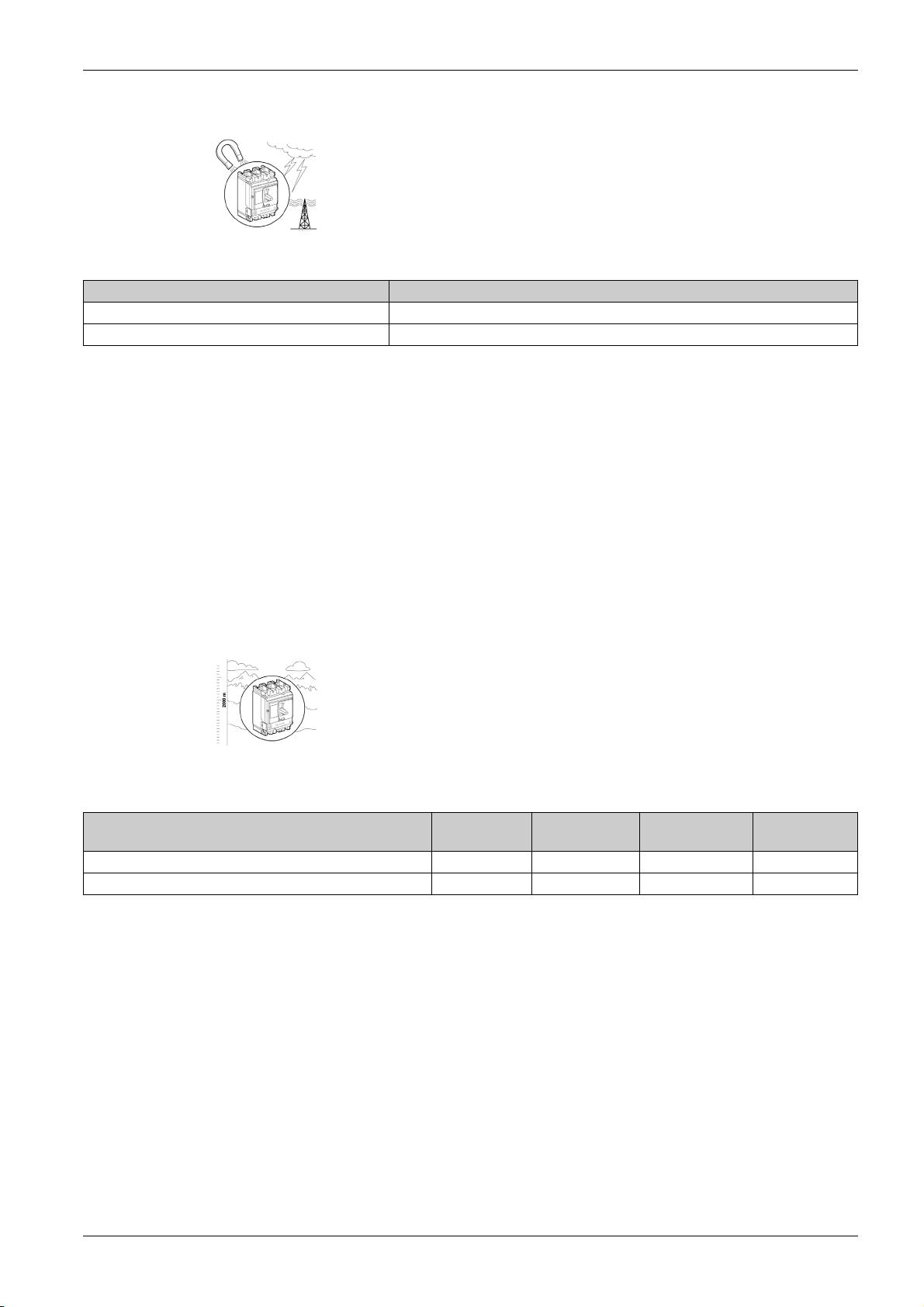
Extreme Atmospheric Conditions
Compact NSX circuit breakers are designed to operate in industrial atmospheres as defined in standard
IEC/EN 60947-2 for the highest level of pollution (level 3).
They are tested for extreme storage conditions according to the following standards:
Standard Title
IEC/EN 60068-2-2 Dry heat, severity level +85 °C (+185 °F)
IEC/EN 60068-2-1 Dry cold, severity level –55 °C (–67 °F)
IEC/EN 60068-2-30 Damp heat, cyclic
IEC/EN 60068-2-52 Salt-mist test
To obtain the best use from the circuit breakers, install them in properly ventilated switchboards where
excessive dust is not a problem.
Vibration
Compact NSX circuit breakers are tested against vibration.
temperature +55 °C (+131 °F)
relative humidity 95 %
22
Conformity tests are carried out in accordance with standard IEC/EN 60068-2-6 at the levels of severity
required by the merchant shipping regulatory bodies (IACS, Veritas, Lloyd namely):
2 Hz to 13.2 Hz with an amplitude of +/- 1 mm (+/- 0.04 in)
13.2 Hz to 100 Hz at a constant acceleration of 0.7 g
DOCA0140EN-01 01/2020
Page 23
Electromagnetic Disturbances
Compact NSX circuit breakers are immune to electromagnetic disturbance.
They comply with the requirements of the electromagnetic compatibility (EMC) standard:
Standard Title
IEC/EN 60947-2 appendixes F and J Overcurrent protection tests
IEC/EN 60947-2 appendixes B and J Specific tests for earth-leakage protection
Check for compliance with EMC standards by testing for immunity to:
Overvoltages produced by the operation of electromagnetic switchgear.
Overvoltages produced by atmospheric disturbance that pass through the electrical network (for
example, lightning).
The use of apparatus emitting radio waves (such as radio transmitters, walkie-talkies, or radar).
Electrostatic discharges produced by the operators themselves.
Conformity with EMC standards as described above helps to ensure that:
The circuit breaker operates correctly in a disturbed environment:
Without nuisance tripping.
In accordance with the trip time.
There is no disturbance to any type of industrial or commercial environment.
Compact NSX Circuit Breakers
Altitude
Compact NSX circuit breakers are designed to operate within specification at altitudes of up to 2,000 m
(6,600 ft).
Above 2,000 m (6,600 ft) modifying the characteristics of the surrounding air (dielectric strength, cooling
capacity) causes derating as follows:
Altitude (m/ft) < 2,000 m
(6,600 ft)
Maximum operating voltage (V) 690 590 520 460
Rated thermal current (A) at 40 °C (104 °F) In 0.96 x In 0.93 x In 0.9 x In
3,000 m
(9,800 ft)
4,000 m
(13,000 ft)
5,000 m
(16,500 ft)
DOCA0140EN-01 01/2020 23
Page 24

Compact NSX Circuit Breakers
Circuit Breaker With Toggle Handle
Section 1.2
Circuit Breaker With Toggle Handle
What Is in This Section?
This section contains the following topics:
Front Face Description 25
Opening, Closing, and Resetting the Circuit Breaker 26
Testing the Circuit Breaker 28
Locking the Circuit Breaker 29
Topic Page
24
DOCA0140EN-01 01/2020
Page 25
Front Face Description
Front Face
Compact NSX Circuit Breakers
A Faceplate
B Toggle handle for opening, closing, and resetting
C Push-to-trip button
D Trip unit setting range
E Trip unit
F Trip unit adjustment dials
For more information about trip units, refer to the related description
(see page 85)
.
DOCA0140EN-01 01/2020 25
Page 26
Compact NSX Circuit Breakers
Opening, Closing, and Resetting the Circuit Breaker
Opening and Closing Locally
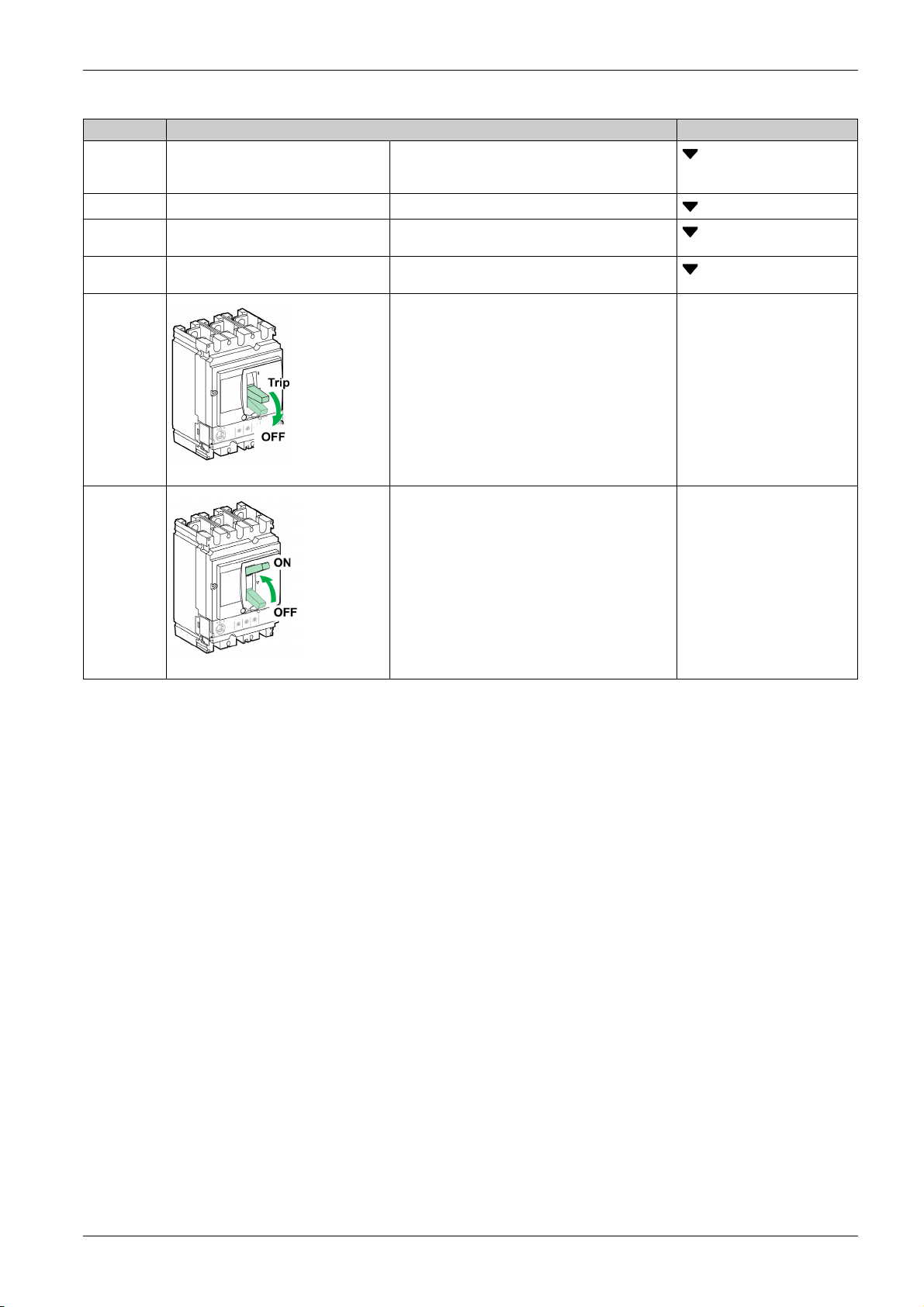
To close the circuit breaker, move the toggle handle from the O(OFF) position to the I(ON) position.
To open the circuit breaker, move the toggle handle from the I(ON) position to the O (OFF) position.
Resetting After a Trip on Electrical Fault
The circuit breaker has tripped on electrical fault, the toggle handle has moved from the I(ON) position to
the Trip position.
WARNING
HAZARD OF CLOSING ON ELECTRICAL FAULT
Do not close the circuit breaker again without first inspecting and, if necessary, repairing the downstream
electrical equipment.
Failure to follow these instructions can result in death, serious injury, or equipment damage.
The fact that a circuit breaker has tripped does not remedy the cause of the fault detected on the
downstream electrical equipment.
26
DOCA0140EN-01 01/2020
Page 27
Compact NSX Circuit Breakers
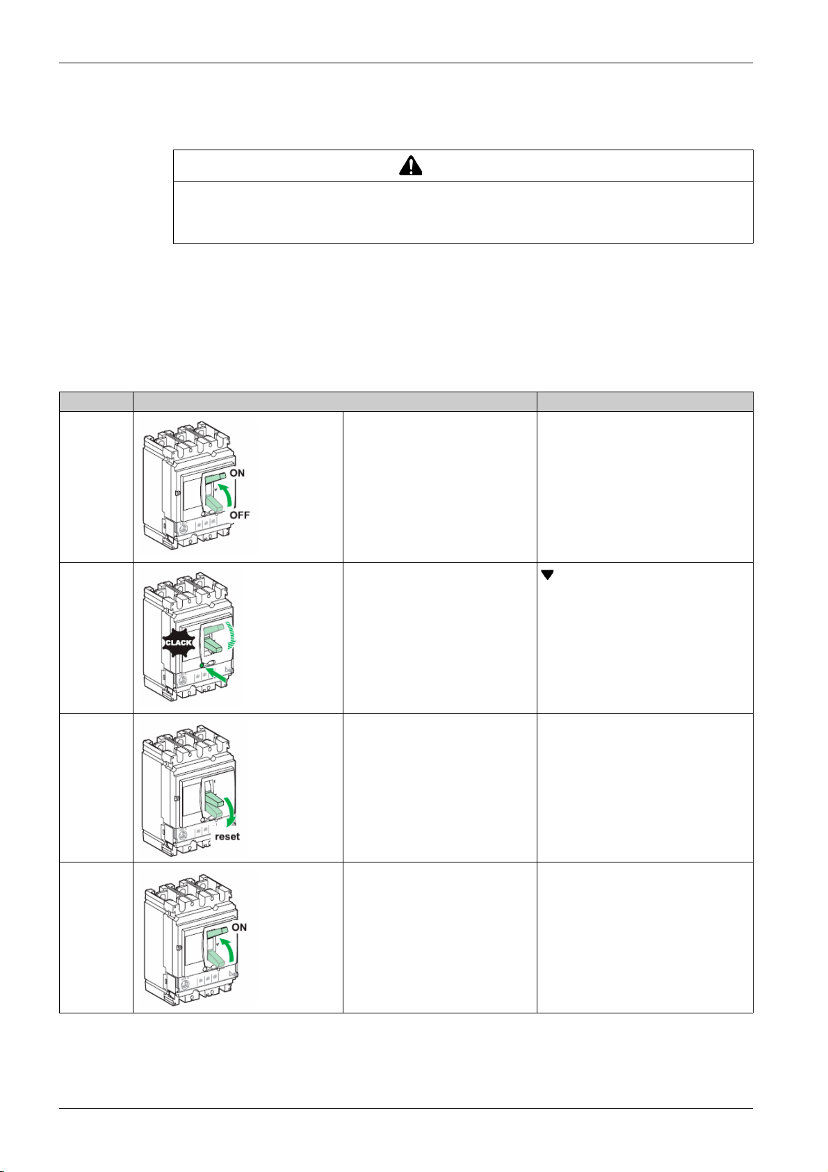
To reset after a fault trip:
Step Action Position
1 – Isolate the feed (refer to maintenance and servicing
work on installation
inspecting the downstream electrical equipment.
2 – Look for the cause of the detected fault.
3 – Inspect and, if necessary, repair the downstream
equipment.
4 – Inspect the equipment in the event of a short-circuit
trip.
5 Reset the circuit breaker by moving the toggle
handle to O(OFF).
(see page 20)
) before
O (OFF)
6 Close the circuit breaker by moving the toggle
handle to I(ON).
I(ON)
DOCA0140EN-01 01/2020 27
Page 28
Compact NSX Circuit Breakers
Testing the Circuit Breaker
Push-to-Trip Procedure
CAUTION
HAZARD OF NUISANCE TRIPPING
Circuit breaker tests must only be done by qualified electrical personnel.
Failure to follow these instructions can result in injury or equipment damage.
When testing the trip mechanism take precautions against:
Disrupting operations
Activating inappropriate alarms
Triggering unwanted actions
For example, tripping the circuit breaker with the push-to-trip button can lead to inappropriate fault
indications or corrective actions (such as switching to an alternate power source).
Follow these steps to test the trip mechanism:
Step Action Position
1 Close the circuit breaker. I (ON)
2 Press the push-to-trip button to trip the
circuit breaker.
3 Move the toggle handle to the
O(OFF) position to reset the circuit
breaker.
4 Move the toggle handle to the I(ON)
position to close the circuit breaker.
O(OFF)
I(ON)
28
DOCA0140EN-01 01/2020
Page 29
Locking the Circuit Breaker
Locking Accessories
HAZARD OF ELECTRIC SHOCK, EXPLOSION, OR ARC FLASH
When the circuit breaker toggle handle is locked in the (O) OFF position, always use a properly rated
voltage sensing device to confirm that power is off before working on equipment.
Failure to follow these instructions will result in death or serious injury.
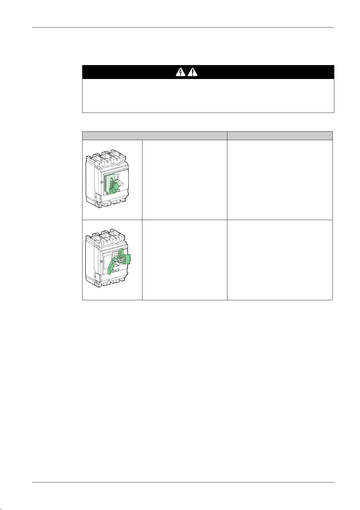
Use locking accessories to lock the toggle handle in the I(ON) or O (OFF) position.
Accessory Padlocks
Compact NSX Circuit Breakers
DANGER
Accessory that is part of the case Use up to 3 padlocks (not supplied) 5–8 mm
(0.2–0.3 in) in diameter
Accessory that is detachable Use up to 3 padlocks (not supplied) 5–8 mm
NOTE: Locking the toggle handle in the I(ON) position does not disable the circuit breaker protection
functions. If there is an electrical fault, the circuit breaker trips without altering its performance. When
unlocked, the toggle handle moves to the Trip position. To return the circuit breaker to service, refer to how
to open, close, and reset the circuit breaker
(see page 26)
(0.2–0.3 in) in diameter
.
DOCA0140EN-01 01/2020 29
Page 30
Compact NSX Circuit Breakers
Sealing Accessories
Use sealing accessories to prevent circuit breaker operations.
Seal Prohibited operations
Escutcheon mounting screw
Dismantling the escutcheon
Accessing the auxiliaries
Dismantling the trip unit
Transparent protective cover
Altering trip unit settings
Accessing the test port for the trip
units
Mounting screw for terminal shields Accessing the power connection
(protection against direct contact)
30
DOCA0140EN-01 01/2020
Page 31

Circuit Breaker With Rotary Handle
Section 1.3
Circuit Breaker With Rotary Handle
What Is in This Section?
This section contains the following topics:
Front Face Description 32
Opening, Closing, and Resetting the Circuit Breaker 34
Testing a Circuit Breaker With Direct Rotary Handle 36
Locking a Circuit Breaker With Direct Rotary Handle 37
Testing a Circuit Breaker With Extended Rotary Handle 40
Locking a Circuit Breaker With Extended Rotary Handle 42
Compact NSX Circuit Breakers
Topic Page
DOCA0140EN-01 01/2020 31
Page 32

Compact NSX Circuit Breakers
Front Face Description
Front Face with Direct Rotary Handle
The circuit breaker operating controls, operation indicators, settings, and locking mechanisms for the direct
rotary handle are on the front of the circuit breaker.
There are two models of rotary handle:
Black handle for standard applications
Red handle on yellow bezel for machine control applications
A Faceplate
B Direct rotary handle for opening, closing, and
resetting
C Push-to-trip button
D Trip unit
E Trip unit adjustment dials
For more information about trip units, refer to the related description
(see page 85)
.
32
DOCA0140EN-01 01/2020
Page 33

Front Face with Extended Rotary Handle
For circuit breakers with an extended rotary handle:
The circuit breaker operating controls are on the door escutcheon.
The operation indicators and settings are only accessible when the door is open
The locking mechanisms are on the circuit breaker (optional) and on the door escutcheon (door closed)
(see page 42)
.
There are two models of extended rotary handle:
Black handle for standard applications
Red handle on yellow bezel for machine control applications
Cabinet door open Cabinet door closed
Compact NSX Circuit Breakers
A Faceplate
B Open door shaft operator
C Push-to-trip button
D Trip unit
E Trip unit adjustment dials
F Extended rotary handle for opening, closing, and resetting
For more information about trip units, refer to the related description
(see page 85)
.
DOCA0140EN-01 01/2020 33
Page 34

Compact NSX Circuit Breakers
Opening, Closing, and Resetting the Circuit Breaker
Opening and Closing Locally
To close the circuit breaker, turn the rotary handle clockwise from the O (OFF) position to the I(ON)
position.
To open the circuit breaker, turn the rotary handle counterclockwise from the I(ON) position to the
O(OFF) position.
Resetting After a Trip on Electrical Fault
The circuit breaker has tripped on electrical fault, the rotary handle has moved from the I(ON) position to
the Trip position.
WARNING
HAZARD OF CLOSING ON ELECTRICAL FAULT
Do not close the circuit breaker again without first inspecting and, if necessary, repairing the downstream
electrical equipment.
Failure to follow these instructions can result in death, serious injury, or equipment damage.
The fact that a circuit breaker has tripped does not remedy the cause of the fault detected on the
downstream electrical equipment.
To reset after a fault trip:
Step Action Position
1 – Isolate the feed
equipment.
2 – Look for the cause of the detected fault. Trip
3 – Inspect and, if necessary, repair the downstream equipment. Trip
4 – Inspect the equipment in the event of a short-circuit trip. Trip
(see page 20)
before inspecting the downstream electrical
Trip
34
DOCA0140EN-01 01/2020
Page 35

Compact NSX Circuit Breakers
Step Action Position
5 Reset the circuit breaker by turning the rotary handle counterclockwise from
O(OFF)
the Trip position to O(OFF).
6 Close the circuit breaker by turning the rotary handle clockwise to I(ON). I(ON)
DOCA0140EN-01 01/2020 35
Page 36

Compact NSX Circuit Breakers
Testing a Circuit Breaker With Direct Rotary Handle
Push-to-Trip Procedure
CAUTION
HAZARD OF NUISANCE TRIPPING
Circuit breaker tests must only be done by qualified electrical personnel.
Failure to follow these instructions can result in injury or equipment damage.
When testing the trip mechanism, take precautions against:
Disrupting operations
Activating inappropriate alarms
Triggering unwanted actions
For example, tripping the circuit breaker with the push-to-trip button can lead to inappropriate fault
indications or corrective actions (such as switching to an alternate power source).
Follow these steps to test the trip mechanism:
Step Action Comment
1 Close the circuit breaker. I (ON)
2 Press the push-to-trip button: the
circuit breaker trips.
3 Turn the rotary handle
counterclockwise to the O(OFF)
position. The circuit breaker is open.
4 Turn the rotary handle clockwise from
the O(OFF) position to the I(ON)
position. The circuit breaker is closed.
Trip
O(OFF)
I (ON)
36
DOCA0140EN-01 01/2020
Page 37

Locking a Circuit Breaker With Direct Rotary Handle
Locking Accessories
Lock handle with up to three padlocks (not supplied) or a keylock.
Accessory Padlocks
Padlocking (standard) only in the O(OFF) position. Lock handle with up to three padlocks (not
supplied) with shackle diameters of 5–8 mm (0.2–
0.3 in).
Compact NSX Circuit Breakers
Padlocking (after modification to the rotary handle
during installation) in the two positions I(ON) and
O(OFF).
Keylocking with a Profalux® or Ronis® lock
(optional).
The circuit breaker can be locked in the O(OFF)
position only or in the O(OFF) and I(ON) position,
depending on the bolt chosen.
Lock handle with up to three padlocks (not
supplied) with shackle diameters of 5–8 mm (0.2–
0.3 in).
A Profalux or Ronis lock can be installed on site.
Keylocking can be used at the same time as
padlocking.
NOTE: Locking the rotary handle in the I(ON) position does not disable the circuit breaker protection
functions. If there is an electrical fault, the circuit breaker still trips. When unlocked, the handle moves to
the Trip position. To return the circuit breaker to service, follow the resetting instructions
(see page 34)
.
Door Locking (MCC Function)
Further options are offered with the direct rotary handle in the MCC function.
When the circuit breaker is in the I(ON) position, the direct rotary handle locks the door in the closed
position.
DOCA0140EN-01 01/2020 37
Page 38

Compact NSX Circuit Breakers
HAZARD OF ELECTRIC SHOCK, EXPLOSION, OR ARC FLASH
Only qualified persons are authorized to disable the door lock.
Failure to follow these instructions will result in death or serious injury.
Temporarily disable this lock to open the door when the circuit breaker is in the I(ON) position.
Disabling this lock requires modifying the rotary handle. Refer to the instruction sheets on the Schneider
Electric website:
GHD16292AA
GHD16320AA
If the lock has been disabled, the following direct rotary handle functions are inoperative:
Door locking
Preventing the circuit breaker from being closed when the door is open
DANGER
, Direct rotary handle for Compact NSX100-250
, Direct rotary handle for Compact NSX400-630
Preventing Circuit Breaker Closing When the Door Is Open
The door locking device can also help to prevent the direct rotary handle from being moved to the I(ON)
position when the door is open.
Sealing Accessories
Use sealing accessories to prevent circuit breaker operations.
Seal Prohibited operations
Escutcheon mounting screw
Transparent protective cover
Dismantling the escutcheon
Accessing the auxiliaries
Dismantling the trip unit
Altering trip unit settings
Accessing the test port for the trip units
38
DOCA0140EN-01 01/2020
Page 39

Compact NSX Circuit Breakers
Seal Prohibited operations
Mounting screw for terminal shields Accessing the power connection (protection
against direct contact)
DOCA0140EN-01 01/2020 39
Page 40

Compact NSX Circuit Breakers
Testing a Circuit Breaker With Extended Rotary Handle
Push-to-Trip Procedure
CAUTION
HAZARD OF NUISANCE TRIPPING
Circuit breaker tests must only be done by qualified electrical personnel.
Failure to follow these instructions can result in injury or equipment damage.
When testing the trip mechanism take precautions against:
Disrupting operations
Activating inappropriate alarms
Triggering unwanted actions
For example, tripping the circuit breaker with the push-to-trip button can lead to inappropriate fault
indications or corrective actions (such as switching to an alternate power source).
There is no push-to-trip button on the door of a circuit breaker with a front extended rotary handle. To check
the trip mechanism, the door must first be opened.
Follow these steps to test the trip mechanism:
Step Action Position
1 Switch the circuit breaker to the open O(OFF) position. Open the door. O(OFF)
2 Turn the circuit breaker from the O(OFF) position to the I(ON) position,
using one of the following tools:
An open door shaft operator (LV426937).
A flat wrench, taking care not to damage the extension shaft or its
surface treatment.The extension shaft is a hollow rectangular
tube,15 x 10 mm (0.59 x 0.39 in).
The circuit breaker is ready for the test.
3 Press the push-to-trip button. The circuit breaker trips. Trip
4 Use a special tool (refer to step 2) to turn the extension shaft
counterclockwise and switch the circuit breaker from the Trip position to
the O(OFF) position. The circuit breaker is in the open position.
I(ON)
O(OFF)
40
DOCA0140EN-01 01/2020
Page 41

Compact NSX Circuit Breakers
Step Action Position
5 Close the door. –
DOCA0140EN-01 01/2020 41
Page 42

Compact NSX Circuit Breakers
Locking a Circuit Breaker With Extended Rotary Handle
Locking Accessories
The extended rotary handle offers several locking functions to:
Prevent the rotary handle being operated.
Prevent the door being opened.
Some locking functions can be disabled on different adaptations.
The handle can be locked with up to three padlocks (not supplied) or keylock.
Accessory Padlocks
Padlocking (standard) in the O (OFF) position.
Padlocking the rotary handle in the O(OFF)
position does not prevent the door from
opening.
Lock rotary handle with up to three padlocks
(not supplied) with shackle diameters of 5–
8 mm (0.2–0.3 in).
Padlocking (after modification to the rotary
handle during installation) in the two positions
I(ON) and O(OFF).
There is a choice of two options when locking
the rotary handle in the I(ON) position:
Standard with the door opening locked.
As an option, door is not interlocked, and
locking the rotary handle does not stop the
door from opening.
Keylocking with a Profalux® or Ronis® lock
(optional).
The lock is mounted on the case inside the
switchboard.
Lock the circuit breaker in the O(OFF) position
only or in the O(OFF) and I(ON) positions
depending on the bolt chosen.
Lock rotary handle with up to three padlocks
(not supplied) with shackle diameters of 5–
8 mm (0.2–0.3 in).
A Profalux or Ronis lock can be installed on
site. Keylocking can be used at the same time
as padlocking.
NOTE: Locking the rotary handle in the I(ON) position does not disable the circuit breaker protection
functions. If there is an electrical fault, the circuit breaker still trips. When unlocked, the rotary handle
moves to the Trip position. To return the circuit breaker to service, follow the resetting instructions
(see page 34)
.
Door Locking (MCC Function)
The extended rotary handle locks the door in the I(ON) position as standard.
42
DOCA0140EN-01 01/2020
Page 43

Compact NSX Circuit Breakers
DANGER
HAZARD OF ELECTRIC SHOCK, EXPLOSION, OR ARC FLASH
Only qualified persons are authorized to disable the door lock.
Failure to follow these instructions will result in death or serious injury.
Temporarily disable this lock to open the door when the circuit breaker is in the I(ON) position.
Disabling this lock requires modifying the rotary handle. Refer to the instruction sheets on the Schneider
Electric website:
GHD16292AA
GHD16320AA
Example: An application includes a circuit breaker for a switchboard incoming supply and several receiver
circuit breakers with extended rotary handles installed behind the same door. Locking the door with a single
rotary handle (incoming supply circuit breaker) simplifies maintenance work on the switchboard.
, Extended rotary handle for Compact NSX100-250
, Extended rotary handle for Compact NSX400-630
Key-Operated Locking Procedure
Keylocking can be done with circuit breaker in either the O (OFF) position or the I(ON) position.
Step Action (circuit breaker in the O (OFF) position) Action (circuit breaker in the I (ON) position)
1 Open the door. Open the door by disabling the door locking device if necessary.
2 Use the keylock mounted on the case inside the switchboard to
lock the rotary handle.
3 Close the door. Close the door, disabling the door locking device if necessary.
Use the keylock mounted on the case inside the switchboard to
lock the rotary handle.
Sealing Accessories
The sealing accessories for circuit breakers with extended rotary handles are identical to those for circuit
breakers with direct rotary handles
(see page 37)
.
DOCA0140EN-01 01/2020 43
Page 44

Compact NSX Circuit Breakers
Motor-Operated Circuit Breakers
Section 1.4
Motor-Operated Circuit Breakers
What Is in This Section?
This section contains the following topics:
Front Face Description 45
Opening, Closing, and Resetting a Circuit Breaker With Motor Mechanism 47
Opening, Closing, and Resetting Circuit Breakers With Communicating Motor Mechanism 50
Locking the Circuit Breaker 51
Topic Page
44
DOCA0140EN-01 01/2020
Page 45

Front Face Description
Front Face
The main controls, operation indicators, settings, and locking mechanisms are on the front of an
electrically-operated circuit breaker (with motor mechanism).
Compact NSX Circuit Breakers
A Faceplate
B Charging handle
C Keylocking in O(OFF) position (option available for Compact NSX400-630 only)
D Sealing accessory
E Main contacts position indicator
F Spring-charged and ready-to-close indicator
G Padlocking in O(OFF) position
H Closing (I(ON)) and opening (O(OFF)) pushbuttons
I Manual/automatic operating mode selector
J Trip unit
Main Contacts Position Indicator
Indicator Description
NOTE: Use the SD or SDE auxiliary contact to distinguish the Trip position from the O (OFF) position.
Spring-Charged and Ready-to-Close Indicator
Indicator Description
The circuit breaker is closed.
The circuit breaker is open or tripped.
Closing spring charged
Closing spring discharged
NOTE: The closing spring only provides the necessary energy for circuit breaker closing. The circuit
breaker mechanism supplies the energy for tripping.
DOCA0140EN-01 01/2020 45
Page 46

Compact NSX Circuit Breakers
Manu/Auto Selector
The Manu/Auto button selects the operating mode:
In automatic operating mode, only electrical commands are executed.
In manual operating mode, all electrical commands are disabled.
46
DOCA0140EN-01 01/2020
Page 47

Opening, Closing, and Resetting a Circuit Breaker With Motor Mechanism
Introduction
The motor mechanism can open and close a circuit breaker remotely with electrical commands. There are
many applications:
Automation of electrical distribution to optimize operating costs
Normal/standby source changeover: changes over to a replacement source to improve continuity of
service
Load shedding/reconnection to optimize tariff-based contracts
CAUTION
HAZARD OF REPEATED CLOSING ON ELECTRICAL FAULT
Do not modify the wiring diagrams for the motor mechanism.
Failure to follow these instructions can result in injury or equipment damage.
Compact NSX Circuit Breakers
Wire the motor mechanism in strict accordance with the motor mechanism wiring diagram in the Appendix
(see page 161)
.
In automatic operating mode, wiring the SDE contact helps to prevent the circuit breaker from resetting
automatically on an electrical fault. For more information about the SDE contact, refer to the indication
contacts
(seepage70)
.
Manual Operation: Opening, Closing, and Resetting Locally
Move the selector to the Manu position.
Cycle of operation:
Manual Operation Description
Check that the spring-charged indicator is on charged (A). If not, reset the circuit breaker.
Step Action Comment
1
Close the circuit breaker by pressing the closing pushbutton .
2 Open the circuit breaker by pressing the opening pushbutton .When the circuit breaker is open:
3 Reset the circuit breaker: recharge the closing spring by operating
the charging handle (eight times).
DOCA0140EN-01 01/2020 47
When the circuit breaker is closed:
The contact position indicator (B) changes to
I(ON).
The spring-charged indicator (C) changes to
discharged.
The contact position indicator (D) changes to
O(OFF).
The spring-charged indicator (E) stays on
discharged.
When the circuit breaker is ready to be closed:
The contact position indicator (F) stays on
O(OFF).
The spring-charged indicator (A) changes to
charged.
Page 48

Compact NSX Circuit Breakers
Automatic Operation: Opening, Closing, and Resetting Remotely
Move the selector to the Auto position.
Cycle of operation:
Automatic Operation Description
Step Action Comment
1 Close the circuit breaker by sending a close (ON) command. When the circuit breaker is closed:
2 Open the circuit breaker by sending an open (OFF) command. When the circuit breaker is open:
3 Recharge the stored energy control by using one of the three reset
modes, depending on the wiring diagram:
Automatic reset
Remote reset by using the pushbutton
Manual reset by operating the charging handle
The contact position indicator (A) changes to
I(ON).
The spring-charged indicator (B) changes to
discharged.
The contact position indicator (C) changes to
O(OFF).
The spring-charged indicator (D) stays on
discharged.
The circuit breaker is ready to be closed:
The contact position indicator (E) stays on
O(OFF).
The spring-charged indicator (F) changes to
charged.
Resetting After a Trip on Electrical Fault
Resetting after a trip on electrical fault can only be done locally. When operating in automatic mode, return
to manual operation to reset the circuit breaker.
HAZARD OF CLOSING ON ELECTRICAL FAULT
Do not close the circuit breaker again without first inspecting and, if necessary, repairing the downstream
electrical equipment.
Failure to follow these instructions can result in death, serious injury, or equipment damage.
The fact that a protection has tripped the circuit breaker does not remedy the cause of the fault detected
on the downstream electrical equipment.
WARNING
48
DOCA0140EN-01 01/2020
Page 49

Compact NSX Circuit Breakers
To reset after a fault trip:
Step Action
1 Isolate the feed
(see page 20)
2 With selector on Manu, operate the charging handle 8 times to reset the circuit breaker in ready-to-close position.
Result: The spring-charged indicator changes to charged (B) and the internal mechanism goes from the Trip position to the
O(OFF) position (A).
3 Lock the circuit breaker.
4 Look for the cause of the detected fault.
5 Inspect and, if necessary, repair the downstream equipment.
6 Inspect the equipment in the event of a short-circuit trip.
7 Reset and close the circuit breaker.
before inspecting the downstream electrical equipment.
DOCA0140EN-01 01/2020 49
Page 50

Compact NSX Circuit Breakers
Opening, Closing, and Resetting Circuit Breakers With Communicating Motor Mechanism
Introduction
Manage the communicating motor mechanism with the communication network.
For this function, it is necessary to:
Install a Breaker Status Control Module (BSCM)
Use a communicating motor mechanism.
(see page 77)
and the NSX cord
(see page 79)
Connect the BSCM module to the communication network with the NSX cord:
To receive closing, opening, and reset commands.
To transmit the circuit breaker states: O(OFF), I(ON), Tripped by SDE.
NOTE: The communicating motor mechanism has a specific reference. For more information, refer to
Compact NSX & NSXm Catalogue
The BSCM module can be configured using EcoStruxure Power Commission software.
.
(see page 19)
The schematic for the communicating motor mechanism in the BSCM module can be configured. It must
be created in strict accordance with the simplified schematic shown in the appendix
(see page 170)
CAUTION
HAZARD OF REPEATED CLOSING ON ELECTRICAL FAULT
Do not modify the wiring diagrams for the motor mechanism.
Failure to follow these instructions can result in injury or equipment damage.
.
.
Manual Operation: Opening, Closing, and Resetting Locally
The process is the same as the standard motor mechanism.
Automatic Operation: Opening, Closing, and Resetting Remotely
The process is the same as the standard motor mechanism.
Resetting After a Trip on Electrical Fault
Without modifying the factory configuration, the process is the same as the standard motor mechanism
(see page 48)
.
Reconfiguration of the BSCM module using EcoStruxure Power Commission software
authorizes remote resetting after a trip on electrical fault on a circuit breaker with communicating motor
mechanism.
(see page 78)
50
DOCA0140EN-01 01/2020
Page 51

Locking the Circuit Breaker
Locking Accessories
DANGER
HAZARD OF ELECTRIC SHOCK, EXPLOSION, OR ARC FLASH
When the circuit breaker toggle handle is locked in the (O) OFF position, always use a properly rated
voltage sensing device to confirm that power is off before working on equipment.
Failure to follow these instructions will result in death or serious injury.
Lock the mechanism with up to three padlocks (not supplied) or a keylock.
Both locking methods can be used at the same time.
Step Action Comment Result
1 Switch the circuit breaker to the
O (OFF) position.
2 Pull out the tab –
–
Compact NSX Circuit Breakers
3 Lock the tab using:
Up to three padlocks 5-8 mm (0.2-
0.3 in) in diameter.
A keylock (optional).
The circuit breaker is locked.
No commands in Auto mode or
Manu mode are executed.
Sealing Accessories
Use sealing accessories to prevent circuit breaker operations.
Seal Prohibited operations
Motor mechanism mounting screw
Transparent cover for the motor
mechanism
Dismantling the escutcheon
Accessing the auxiliaries
Dismantling the trip unit
Accessing the manual/automatic
selector (depending on its position,
manual operation
(1)
operation is disabled).
, or automatic
Transparent protective cover for the trip
units
Altering any settings and accessing the
test port.
(1) In this case no local operations are possible.
DOCA0140EN-01 01/2020 51
Page 52

Compact NSX Circuit Breakers
Seal Prohibited operations
Mounting screw for terminal shields Accessing the power connection
(protection against direct contact)
(1) In this case no local operations are possible.
52
DOCA0140EN-01 01/2020
Page 53

CompactNSX
CompactNSX Installation Accessories
DOCA0140EN-01 01/2020
Compact NSX Instal lation Accessories
Chapter 2
Compact NSX Installation Accessories
What Is in This Chapter?
This chapter contains the following topics:
Plug-in Circuit Breaker 54
Withdrawable Circuit Breaker 58
Accessories 64
Topic Page
DOCA0140EN-01 01/2020 53
Page 54

Compact NSX Installation Accessories
Plug-in Circuit Breaker
Introduction
Plug-in base circuit breakers make it possible to:
Extract and/or rapidly replace the circuit breaker without having to touch the connections on the base
Allow for the addition of future circuits by installing bases that will be equipped with a circuit breaker at
a later date
Isolate the power circuits when the circuit breaker is mounted on or through a panel. It acts as a barrier
for the connections of the plug-in base. Insulation is made complete by the mandatory short terminal
shields on the circuit breaker
The following types of circuit breaker can be installed in a plug-in base:
3P and 4P circuit breakers
Circuit breakers with toggle handle, direct rotary handle, or extended rotary handle
Motor-operated circuit breakers
Circuit breakers with Vigi module
The plug-in circuit breaker is made up of the fixed circuit breaker and a plug-in kit, which includes:
Plug-in base
Power connections
Short terminal shields
Safety trip interlock
Disconnecting the Circuit Breaker
(see page 56)
.
DANGER
HAZARD OF ELECTRIC SHOCK, EXPLOSION, OR ARC FLASH
Apply appropriate personal protective equipment (PPE) and follow safe electrical work practices. See
NFPA 70E, CSA Z462, NOM-029-STPS, or local equivalent.
This equipment must only be installed and serviced by qualified electrical personnel.
The circuit breaker must be in the O (OFF) position.
Do not use tools to disconnect or connect the circuit breaker.
Failure to follow these instructions will result in death or serious injury.
Follow this procedure to disconnect the circuit beaker:
Step Action
1 Switch the circuit breaker to the O(OFF) position.
2 Remove both mounting screws.
54
DOCA0140EN-01 01/2020
Page 55

Step Action
3 Pull out the circuit breaker, keeping it horizontal.
NOTE:
The auxiliary circuits automatically disconnect because of the connectors located on the base and at
the rear of the circuit breaker.
Open the circuit breaker before disconnecting it. If the circuit breaker is in the closed I(ON) position
when disconnecting, a pre-trip mechanism trips the circuit breaker before the pins are disconnected.
Connecting the Circuit Breaker
Compact NSX Installation Accessories
DANGER
HAZARD OF ELECTRIC SHOCK, EXPLOSION, OR ARC FLASH
Apply appropriate personal protective equipment (PPE) and follow safe electrical work practices. See
NFPA 70E, CSA Z462, NOM-029-STPS, or local equivalent.
This equipment must only be installed and serviced by qualified electrical personnel.
The circuit breaker must be in the O (OFF) position.
Do not use tools to disconnect or connect the circuit breaker.
Failure to follow these instructions will result in death or serious injury.
Follow this procedure to connect the circuit beaker:
Step Action
1 Switch the circuit breaker to the O(OFF) position.
2 Connect the circuit breaker.
DOCA0140EN-01 01/2020 55
Page 56

Compact NSX Installation Accessories
Step Action
3 Replace both mounting screws. Tighten the screws to a
NOTE:
The auxiliary circuits automatically connect because of the connectors located on the base and at the
rear of the circuit breaker.
Open the circuit breaker before connecting it. If the circuit breaker is in the closed I(ON) position when
connecting, the pre-trip mechanism trips the circuit breaker before the pins are connected.
Protection Against Direct Contact With Power Circuits
The following table shows plug-in circuit breaker configurations with the corresponding protection indices
(IP):
torque of 2.5 N•m (22.1 lb-in).
Configuration Protection
index
IP20 Built-in plug-in base:
IP40 Built-in plug-in base and circuit breaker with terminal shields.
Description
Without circuit breaker
With circuit breaker without terminal shields
56
IP40 Plug-in base with adapter, terminal shields and blanking plate without
circuit breaker:
The adapter enables the use of all the connection accessories of the
fixed circuit breaker. It is required to equip the plug-in circuit breaker
with long and short terminal shields and interphase barriers.
Terminal shields are mandatory for plug-in circuit breakers. Short
terminal shields are supplied in the plug-in kit. They can be replaced by
long terminal shields available as an option.
The blanking plate is not supplied by Schneider Electric.
DOCA0140EN-01 01/2020
Page 57

Compact NSX Installation Accessories
Configuration Protection
index
IP40 Plug-in base with adapter and terminal shields, and circuit breaker with
For more information about configurations and installation, consult the instruction sheets on the Schneider
Electric website:
GHD16276AA
GHD16316AA
, Plug-in base for Compact NSX100-250
, Plug-in base for Compact NSX400-630
Description
terminal shields.
DOCA0140EN-01 01/2020 57
Page 58

Compact NSX Installation Accessories
Withdrawable Circuit Breaker
Introduction
In addition to the advantages provided by a plug-in base, installation of the circuit breaker on a chassis
facilitates handling. Withdrawable chassis circuit breakers offer three positions, with transfer from one to
the other after mechanical unlocking:
Connected: the power circuits are connected.
Disconnected: the power circuits are disconnected, the circuit breaker can be operated to check
auxiliary operation.
Removed: the circuit breaker is free and can be removed from the chassis.
The following types of circuit breaker can be installed in a chassis:
3P and 4P circuit breakers
Circuit breakers with toggle handle, direct rotary handle, or extended rotary handle
Motor-operated circuit breakers
Circuit breakers with Vigi module
The withdrawable circuit breaker is made up of:
The fixed circuit breaker
A plug-in kit
Two chassis side plates for the plug-in base
Two chassis side plates for the circuit breaker
Disconnecting the Circuit Breaker
DANGER
HAZARD OF ELECTRIC SHOCK, EXPLOSION, OR ARC FLASH
Apply appropriate personal protective equipment (PPE) and follow safe electrical work practices. See
NFPA 70E, CSA Z462, NOM-029-STPS, or local equivalent.
This equipment must only be installed and serviced by qualified electrical personnel.
The circuit breaker must be in the O (OFF) position.
Do not use tools to disconnect or connect the circuit breaker.
Failure to follow these instructions will result in death or serious injury.
Follow this procedure to disconnect the circuit breaker:
Step Action
1 Switch the circuit breaker to the O(OFF)
2 Move both locking levers down as far as
position.
they can go.
58
DOCA0140EN-01 01/2020
Page 59

Compact NSX Installation Accessories
Step Action
3 Push down both operating handles at the
same time until you hear a double-click from
the locking levers (as the locking levers
return to their original position).
The circuit breaker is disconnected.
NOTE:
The auxiliary circuits can be:
Automatically disconnected because of the connectors located on the chassis and at the rear of the
circuit breaker.
Left connected for a circuit breaker with a manual auxiliary connector.
Open the circuit breaker before disconnecting it. If the circuit breaker is in the closed I(ON) position
when disconnecting, a safety mechanism ensures that the poles open automatically by tripping the
circuit breaker before the pins disconnect.
Removing the Circuit Breaker
HAZARD OF ELECTRIC SHOCK, EXPLOSION, OR ARC FLASH
Apply appropriate personal protective equipment (PPE) and follow safe electrical work practices. See
NFPA 70E, CSA Z462, NOM-029-STPS, or local equivalent.
This equipment must only be installed and serviced by qualified electrical personnel.
The circuit breaker must be in the O (OFF) position.
Do not use tools to disconnect or connect the circuit breaker.
Failure to follow these instructions will result in death or serious injury.
Follow this procedure to remove the circuit breaker:
Step Action
1 Move both locking levers down.
DANGER
2 Push down both operating handles as far as
DOCA0140EN-01 01/2020 59
the next notch.
Page 60

Compact NSX Installation Accessories
Step Action
3 Remove the circuit breaker, keeping it
Connecting the Circuit Breaker
HAZARD OF ELECTRIC SHOCK, EXPLOSION, OR ARC FLASH
Apply appropriate personal protective equipment (PPE) and follow safe electrical work practices. See
NFPA 70E, CSA Z462, NOM-029-STPS, or local equivalent.
This equipment must only be installed and serviced by qualified electrical personnel.
The circuit breaker must be in the O (OFF) position.
Do not use tools to disconnect or connect the circuit breaker.
Failure to follow these instructions will result in death or serious injury.
horizontal.
DANGER
Follow this procedure to connect the circuit breaker:
Step Action
1 Switch the circuit breaker to the open
O(OFF) position.
Move both operating handles down to the
low position on the chassis.
Push in the circuit breaker until the locking
levers clicks.
2 Move both locking levers forward.
60
DOCA0140EN-01 01/2020
Page 61

Step Action
3 Raise both locking levers at the same time.
NOTE: Open the circuit breaker before connecting it. If the circuit breaker is in the closed I(ON) position
when connecting, a mechanism opens the poles automatically by tripping the circuit breaker before the
pins connect.
Withdrawable Circuit Breaker Protection Against Direct Contact With Power Circuits
The following table shows withdrawable circuit breaker configurations with the corresponding protection
indices (IP):
Compact NSX Installation Accessories
Configuration Protection
index
IP20 Built-in chassis:
IP40 Built-in chassis and circuit breaker with terminal shields.
Description
Without circuit breaker
With circuit breaker without terminal shields
IP40 Chassis with adapter, terminal shields and blanking plate without circuit
breaker:
The adapter enables the use of all the connection accessories of the
withdrawable circuit breaker. It is required to equip the withdrawable
circuit breaker with long and short terminal shields and interphase
barriers.
Terminal shields are mandatory for withdrawable circuit breakers. Short
terminal shields are supplied in the plug-in kit. They can be replaced by
long terminal shields available as an option.
The blanking plate is not supplied by Schneider Electric.
DOCA0140EN-01 01/2020 61
Page 62

Compact NSX Installation Accessories
Configuration Protection
index
IP40 Chassis with adapter and terminal shields, and circuit breaker with terminal
Description
shields.
For more information about configurations and installation, consult the instruction sheets on the Schneider
Electric website:
GHD16277AA
GHD16317AA
, Chassis side plates for Compact NSX100-250
, Chassis side plates for Compact NSX400-630
Auxiliary Circuit Test with Circuit Breaker Disconnected (Optional)
The auxiliary circuit test function is possible with circuit breakers which have manual auxiliary connectors.
In the disconnected position, operate the circuit breaker (by the actuator or push-to-trip button) to check
whether the auxiliary circuits are working correctly.
Disconnect the manual auxiliary connector (if the circuit breaker has one) before removing the circuit
breaker.
Carriage Switches (Optional)
Two changeover contacts can be installed on the chassis:
A Connected-position carriage switch (CE)
B Disconnected-position carriage switch (CD)
For more information about contact operation, refer to control auxiliaries
Carriage switches, in conjunction with the IO module, provide the chassis management function, which is
used to:
Record and check the position of the moving part of the withdrawable circuit breaker in the chassis
Provide information about preventive maintenance actions
Notify the remote controller about the position of the withdrawable circuit breaker.
For more information about the chassis management function, refer to
Input/Output Application Module for One IEC Circuit Breaker - User Guide
(seepage83)
.
DOCA0055EN, Enerlin'X IO -
,
62
DOCA0140EN-01 01/2020
Page 63

Locking the Chassis
Compact NSX Installation Accessories
The operating handle can be locked with up to four padlocks (not supplied) or keylock.
Illustration Description
Lock the circuit breaker in disconnected position using up to four padlocks (not
supplied) with a shackle diameter of 5–8 mm (0.2–0.3 in) to prevent connection.
Lock the circuit breaker using a keylock (optional) in the connected position
when the locking kit accessory is installed.
Lock the circuit breaker using a keylock (optional) in the disconnected position
when the locking kit accessory is installed.
For more information about the accessory offer, refer to
Compact NSX & NSXm Catalogue
.
DOCA0140EN-01 01/2020 63
Page 64

Compact NSX Installation Accessories
Accessories
Accessories for Compact NSX Circuit Breakers
A comprehensive accessory offer is available for Compact NSX circuit breakers. Accessories can be
installed on site to improve safety and ease of operation.
Sealed boot for the toggle handle, providing
IP43 protection on the front
For more information about the accessory offer, refer to
Terminal Shields with Precut Grids
1 Cutting a grid
2 Adjusting the size of the grid
3 Inserting the grid in the terminal shield
Terminal shields with precut grids simplify the onsite connection of circuit breakers regardless of the
number of conductors to be connected. The procedure for installing precut guides is described in the
following instruction sheets on the Schneider Electric website:
GHD16242AA
GHD16243AA
Short or long terminal shields, providing IP40
protection
, Compact NSX100–250
, Compact NSX400–630
Flexible interphase barriers improving
isolation between power connections
Compact NSX & NSXm Catalogue
.
64
DOCA0140EN-01 01/2020
Page 65

CompactNSX
CompactNSX Electrical Auxiliary Devices
DOCA0140EN-01 01/2020
CompactNSX Electrical Auxiliary Devices
Chapter 3
Compact NSX Electrical Auxiliary Devices
What Is in This Chapter?
This chapter contains the following topics:
Electrical Auxiliary Device Summary 66
Indication Contacts 70
SDx Module 71
SDTAM Module (Micrologic 2 M and 6 E-M) 74
BSCM Breaker Status Control Module 76
NSX Cord 79
Insulated NSX Cord 81
Control Auxiliaries 83
Topic Page
DOCA0140EN-01 01/2020 65
Page 66

Compact NSX Electrical Auxiliary Devices
Electrical Auxiliary Device Summary
Electrical Auxiliary Devices
The following table shows the electrical auxiliary devices that can be added to the Compact NSX circuit
breakers. For more information, refer to
Electrical auxiliary device NSX100 NSX160 NSX250 NSX400 NSX630
1P 2P 3P/4P 1P 2P 3P/4P 1P 3P/4P 3P/4P 3P/4P
OF or SD auxiliary contact – ✔ ✔ – ✔ ✔ – ✔ ✔ ✔
SDE auxiliary contact – – ✔ – – ✔ – ✔ ✔ ✔
SDx module ––✔ ––✔ –✔ ✔ ✔
SDTAM module – – ✔ – – ✔ – ✔ ✔ ✔
MN undervoltage trip release – ✔ ✔ – ✔ ✔ – ✔ ✔ ✔
MX shunt trip release – ✔ ✔ – ✔ ✔ – ✔ ✔ ✔
BSCM breaker status control
mode
NSX cord ––✔ ––✔ –✔ ✔ ✔
––✔ ––✔ –✔ ✔ ✔
Slots for Electrical Auxiliary Devices on Compact NSX100/160 2P Circuit Breakers
The following table shows the possible slots for electrical auxiliary devices mounted in the case. Only one
auxiliary device can be installed per slot. For more information, refer to
Compact NSX & NSXm Catalogue
Compact NSX & NSXm Catalogue
.
.
Name Slot
A B C
OF1 ✔ – –
SD – ✔ –
MN – – ✔
MX – – ✔
Slots for Electrical Auxiliary Devices on Compact NSX100-250 3P/4P Circuit Breakers
The following table shows the possible slots for electrical auxiliary devices mounted in the case. Only one
auxiliary device can be installed per slot. For more information, refer to
Compact NSX & NSXm Catalogue
.
66
DOCA0140EN-01 01/2020
Page 67

Compact NSX Electrical Auxiliary Devices
Name Slot Comments
A B C D E F
Standard remote indication and control auxiliaries
OF1 ✔ – – – – – For all trip unit types and control types (toggle handle, rotary
OF2 –––✔––
SD –✔––––
SDE ––✔–––
SDV – – – – – ✔ Indication contact in Vigi module
MN – – – – ✔ – For all trip unit types and control types (toggle handle, rotary
MX ––––✔–
Remote indication on communication network
BSCM – – ✔ ✔ – – For connection of the BSCM module to the communication
NSX cord –✔––––
NSX cord – – – ✔ – – For connection of the Micrologic 5, 6, and 7 trip units to the
Specific remote indication with Micrologic trip units
SDx ✔ – – – ✔ – Including SDV for Micrologic 4 and 7 trip units.
SDTAM ✔ – – – ✔ – Only for circuit breakers with a Micrologic 2 M or 6 E-M trip unit
24 Vdc power supply terminal block – – – ✔ – – Only for Micrologic 5, 6, and 7 trip units.
handle, or motor mechanism).
handle, or motor mechanism).
network.
communication network when no BSCM module is installed.
designed to protect motors.
NOTE: It is not possible to install all the accessories at the same time on one trip unit. For example, the
SDx remote indication option cannot be installed at the same time as an MN or MX release and the
OF1 contact.
Slots for Electrical Auxiliary Devices on Compact NSX400-630 3P/4P Circuit Breakers
Compact NSX400-630 circuit breakers are exclusively equipped with Micrologic trip units.
The following table shows the possible slots for the electrical auxiliary devices mounted in the case. For
more information, refer to
Name Slot Comments
A B C D E F G H I
Standard remote indication and control auxiliaries
OF1 ––✔––––––
OF2 – ✔ – – – – – – – For all trip unit types and control types
OF3 ✔––––––––
OF4 ––––––✔––
SD ––––––––✔
SDE –––––––✔–
SDV – – – – – ✔ – – – Indication contact in Vigi module
Compact NSX & NSXm Catalogue
.
(toggle handle, rotary handle, or motor
mechanism).
DOCA0140EN-01 01/2020 67
Page 68

Compact NSX Electrical Auxiliary Devices
Name Slot Comments
A B C D E F G H I
MN – – – – ✔ – – – – For all trip unit types and control types
MX ––––✔––––
(toggle handle, rotary handle, or motor
mechanism).
Remote indication on communication network
BSCM – – – – – – ✔ ✔ – For connection of the BSCM module to the
NSX cord ––––––✔––
communication network.
NSX cord – – – – – – – – ✔ For connection of the Micrologic 5, 6, and 7
trip units to the communication network
when no BSCM module is installed.
Specific remote indication with Micrologic trip units
SDx – – – ✔ ✔ – – – – Including SDV for Micrologic 4 and 7 trip
units.
SDTAM –––✔✔–––––
24 Vdc power supply terminal
– – – – – – ✔ – – Only for Micrologic 5, 6, and 7 trip units.
block
NOTE: It is not possible to install all the accessories at the same time on one trip unit. For example, the
SDx remote indication option cannot be installed at the same time as an MN or MX release.
Operation of the Auxiliary Indication Contacts
The following table shows the position of the indication contacts (or outputs) relative to the position of the
actuator and main contacts.
Position of the actuator and the main contacts
ON
Tripped by: OFF
MN/MX
PT
(1)
Trip unit
(2)
L S or So I R G
Name Position of indication contacts
OF ✔––––––––
SD – ✔✔✔✔✔✔✔–
SDE –––✔✔✔✔✔–
SDV ––––––✔––
SDx outputs
(3)
SD2SDT –––✔–––––
SD4PAL –––✔–––––
SDG–––––––✔–
SDV ––––––✔––
SDTAM outputs
SD2 Early
SD4 Contactor control
make/break
SDT
–––✔✔–––––
✔: Contact closed, ✔✔: Early-make output (400 ms)
(1) PT: Push-to-trip
(2) L: Long-time protection
S or So: Short-time protection
I: Instantaneous protection
R: Vigi protection (earth-leakage)
G: Ground-fault protection
(3) SDx output assignment can be customized for Micrologic 5, 6, and 7 trip units, by using EcoStruxure Power Commission software.
68
DOCA0140EN-01 01/2020
Page 69

Compact NSX Electrical Auxiliary Devices
NOTE: The indication auxiliary (changeover) contacts are represented in the switchboard by the state of
the Normally Open (NO) contact.
The state of the NO contact is open:
for OF contacts when the circuit breaker is in the O(OFF) position.
for SD, SDE, and SDV contacts when the associated function is not active.
Sequence chart of the OF contacts relative to the main contacts
A Main contacts
B Position of OF changeover contacts
DOCA0140EN-01 01/2020 69
Page 70

Compact NSX Electrical Auxiliary Devices
Indication Contacts
Introduction
One indicator contact model provides OF, SD, SDE, and SDV indication functions. The position of the
contact inside the case determines the function.
Indication contacts are either under the front face of the circuit breaker, under the motor mechanism, or in
the rotary handle. Installation is in a compartment isolated from the power circuits. There are two types:
Standard contact
Low-level contact
Standard and Low-Level Contacts
Standard and low-level contacts are the common point changeover type.
NC Normally Closed contact
NO Normally Open contact
The following table describes the operation of standard and low-level volt-free contacts:
Name Definition
OF auxiliary
Changeover: The NO contact is normally open when the circuit breaker is in the O(OFF) position.
contact
SD auxiliary
contact
SDE auxiliary
contact
SDV auxiliary
contact
Trip indication: The SD contact indicates that the circuit breaker has tripped due to:
Long-time protection
Short-time protection
Ground-fault protection
Earth-leakage protection (trip by Micrologic 4 or 7 trip unit, or by Vigi module)
Operation of the MX or MN voltage releases
Operation of the push-to-trip button
Connecting/Disconnecting the circuit breaker
Manually opening the motor mechanism
Electrical fault indication: The SDE contact indicates that the circuit breaker has tripped on an electrical fault due to:
Long-time protection
Short-time protection
Ground-fault protection
Earth-leakage protection (trip by Micrologic 4 or 7 trip unit, or by Vigi module)
Earth-leakage fault indication: The SDV contact indicates that the circuit breaker has tripped due to an earth-leakage fault
detected by the earth-leakage protection of the Vigi module.
NOTE: Use the SDx module to indicate an earth-leakage fault detected by a Micrologic 4 or 7 or Micrologic 4 AL or 7 AL trip
unit.
70
DOCA0140EN-01 01/2020
Page 71

SDx Module
Introduction
Description
Compact NSX Electrical Auxiliary Devices
An SDx module can be used with Compact NSX circuit breakers equipped with Micrologic trip units.
The SDx module receives data from the trip unit through an optical link:
For Micrologic 2 trip units, one output (non-configurable) for remote monitoring of the thermal trip alarm
For Micrologic 4 trip units, two outputs (non-configurable) for remote monitoring of:
The thermal trip alarm
The earth-leakage trip alarm
For Micrologic 5, 6, and 7, two outputs (configurable) for remote monitoring of alarms
Installation
A Output terminal block
B SDx module
The slots used to install the SDx module depend on the circuit breaker type.
Compact NSX100-250 Compact NSX400-630
The SDx module cannot be installed at the same time as an MN/MX release and OF contact.
DOCA0140EN-01 01/2020 71
Page 72

Compact NSX Electrical Auxiliary Devices
Connection
Connect the SDx module and the outputs in strict accordance with the wiring diagram.
Micrologic 2 Micrologic 4
Micrologic 5 Micrologic 6 Micrologic 7
The characteristics of the SDx module outputs are:
Voltage: 24–415 Vac/Vdc
Current:
Active outputs: 80 mA maximum
Idle outputs: 0.25 mA
Output Assignment Factory Setting
The functions offered by the SDx module outputs depend on the type of trip unit installed with the module
Micrologic Output 1 (SD2/OUT1) Output 2 (SD4/OUT2)
2 Thermal fault indication alarm (SDT) Not available
4 Thermal fault indication alarm (SDT) Earth-leakage fault indication alarm (SDV)
5 Thermal fault indication alarm (SDT) Long-time pre-alarm (PAL Ir).
6 Thermal fault indication alarm (SDT) Ground-fault indication alarm (SDG)
7 Thermal fault indication alarm (SDT) Earth-leakage fault indication alarm (SDV)
Alarm activated as soon as the current in the load
reaches 90% Ir.
NOTE: Outputs SDT, SDG, and SDV return automatically to their initial state when the circuit breaker
closes.
72
DOCA0140EN-01 01/2020
Page 73

Reconfiguring the SDx Module Outputs
Use EcoStruxure Power Commission software to reconfigure the assignment of SDx output 1 (SD2/OUT1)
and output 2 (SD4/OUT2), when they are used with Micrologic 5, 6, and 7 trip units.
For more information about the list of alarms and configuration options using EcoStruxure Power
Commission software, refer to
.
Guide
The operating mode of the outputs can be configured:
Without latching
With latching (the return to the initial state takes place by acknowledging the latched output using the
communication network or the Micrologic keypad)
Time-delayed without latching (the return to the initial state takes place at the end of the time delay)
Forced to the closed state (the return to the initial state takes place by acknowledging the latched output
using the communication network or the Micrologic keypad)
Forced to the open state (the return to the initial state takes place by acknowledging the latched output
using the communication network or the Micrologic keypad)
Compact NSX Electrical Auxiliary Devices
DOCA0141EN, Compact NSX Micrologic 5/6/7 Electronic Trip Units - User
DOCA0140EN-01 01/2020 73
Page 74

Compact NSX Electrical Auxiliary Devices
SDTAM Module (Micrologic 2 M and 6 E-M)
Introduction
An SDTAM module can be used with circuit breakers with a Micrologic 2 M or 6 E-M trip unit designed to
protect motors.
The SDTAM module receives data from the Micrologic trip unit through an optical link and makes available
two outputs assigned to manage tripping due to overload.
Description
A Output terminals
B SDTAM module
C Operating mode adjustment dial
Installation
Connection
The slots used to install the SDTAM module depend on the circuit breaker type.
Compact NSX100-250 Compact NSX400-630
The SDTAM module cannot be installed at the same time as an MN/MX release and OF contact.
Connect the SDTAM module and the two outputs in strict accordance with the wiring diagram.
74
The characteristics of the SDTAM module outputs are:
Voltage: 24–415 Vac/Vdc
Current:
Active outputs: 80 mA maximum
Idle outputs: 0.25 mA
DOCA0140EN-01 01/2020
Page 75

Output Assignment
Contactor Control
Compact NSX Electrical Auxiliary Devices
Output 1 (SD2/OUT1): normally open, indicates thermal faults.
Output 2 (SD4/OUT2): normally closed, opens the contactor KM.
Outputs are activated 400 ms before the circuit breaker trips in the case of:
Long-time protection
Phase-unbalance protection
Locked rotor protection (Micrologic 6 E-M)
Undercurrent protection (Micrologic 6 E-M)
Contactor control by the output 2 signal (SD4/OUT2) optimizes continuity of service and provides the
following additional benefits:
Lower risk of motor deterioration.
Activation of the output indicates that the application is not working normally. Abnormal operation is not
the result of an anomaly or internal fault in the motor-feeder.
The cause of this abnormal operation can be temporary (for example, a voltage drop causing an overly
long starting time).
When the cause of the overload or unbalance has disappeared, the equipment can be powered up again.
NOTE: To control a contactor with a consumption exceeding 80 mA, it is necessary to provide an interface
(RBN or RTBT relay).
Operating Mode
The SDTAM module incorporates an operating mode adjustment dial:
To return the outputs to their initial state following activation:
Manual (SDTAM dial in the OFF position) after canceling the module power supply
Automatic (SDTAM dial on one of the time delay adjustment settings) following a time delay (set from 1
to 15 minutes to allow for the motor cooling time).
DOCA0140EN-01 01/2020 75
Page 76

Compact NSX Electrical Auxiliary Devices
BSCM Breaker Status Control Module
Introduction
The BSCM Breaker Status Control Module can be used to send the following data via the communication
network:
Circuit breaker states from OF, SD, and SDE auxiliary contacts
Control instructions for the communicating motor mechanism (if present): opening, closing, and
resetting
Information to assist the operator: storage of the last 10 events
Use the BSCM module with all Compact NSX circuit breakers equipped with thermal-magnetic and
Micrologic electronic trip units and with all Compact NSX switch-disconnectors.
Installation of the BSCM module requires:
The NSX cord
Pre-installation of the communicating motor mechanism (if present)
For more information about integrating Compact NSX circuit breaker communication functions, refer to:
DOCA0093EN, ULP System (IEC Standard) - User Guide
DOCA0091EN, Compact NSX - Modbus Communication Guide
Description
Marker Data medium Data transmitted Comments
A BSCM module
microswitches
B Connector for the NSX cord Communication network and state of SD
C Connector for the
Micrologic 5, 6, or 7 trip
units
D Connector for the
communicating motor
mechanism
State of OF and SDE contacts The BSCM module takes the place of the auxiliary
contacts in the OF and SDE slots.
The NSX cord goes in the SD slot instead of the
contact through the microswitch on the
NSX cord
Communication network Only with Micrologic 5, 6, or 7 trip units
Controlling the communicating motor
mechanism
Status of the communicating motor
mechanism
auxiliary contact.
Use the connector supplied with the communicating
motor mechanism.
76
DOCA0140EN-01 01/2020
Page 77

Installing the BSCM Module
The slots used to install the BSCM module depend on the circuit breaker type.
Compact NSX100-250 Compact NSX400-630
A BSCM module
B NSX cord
The BSCM module cannot be installed at the same time as an OF contact or the SDE contact.
The BSCM module can be installed on site.
Connecting the BSCM Module
To install the BSCM module:
Plug in the module.
Connect the 4 connectors.
Compact NSX Electrical Auxiliary Devices
Setting Up the BSCM Module
Setting up the BSCM module on the communication network requires no addressing.
LED Indication on BSCM Module
The LED on the BSCM module is only visible when the front of the case is removed. Use the LED indication
on the BSCM module to confirm that the BSCM module is working during commissioning or maintenance
operations.
ULP LED Mode Action
Nominal None
Conflict Remove extra ULP
Degraded Replace BSCM module
Test None
Non-critical
firmware
discrepancy
Non-critical
hardware
discrepancy
Configuration
discrepancy
Critical firmware
discrepancy
Critical hardware
discrepancy
Stop Replace BSCM module
module
at the next maintenance
operation
Upgrade firmware at the
next maintenance
operation
Replace BSCM module
at the next maintenance
operation
Install missing features
Use EcoStruxure Power
Commission software to
check the firmware and
hardware compatibility
and follow the
recommended actions
Power off Check power supply
DOCA0140EN-01 01/2020 77
Page 78

Compact NSX Electrical Auxiliary Devices
Data Provided by the BSCM Module
Configuration Information Can be
reset
All circuit breakers with BSCM module Count of the total number of times the circuit breaker opens and closes (count of
Circuit breakers with BSCM module and
communicating motor mechanism
(1) The user can modify the content of the counter if, for example, the BSCM module is installed or replaced during operation.
(2) Overshooting the threshold results in a medium priority alarm. To acknowledge the alarm, modify the content of the counter or the value
of the threshold.
OF contact operations).
This counter (totalizer) cannot be reset.
Count of the total number of times the circuit breaker opens and closes (count of
OF contact operations)
Maximum number of times the circuit breaker can open and close
Count of the number of fault trips by the circuit breaker (count of SD contact
operations)
Count of the number of electrical fault trips by the circuit breaker (count of SDE
contact operations)
Count of the number of times the communicating motor mechanism opens
Count of the number of times the communicating motor mechanism closes
Maximum number of times the communicating motor mechanism closes
Count of the number of times the communicating motor mechanism resets
(1)
(1)
(2)
(1)
(2)
No
Yes
Yes
Yes
Yes
(1)
No
(1)
Yes
Yes
(1)
Yes
Configuring the BSCM Module
To configure the BSCM module, use a PC running EcoStruxure Power Commission software and
connected to the USB maintenance interface.
The USB maintenance interface must be connected:
To the RJ45 connector of a ULP module (for example, IFM Modbus-SL interface).
To the test port of Micrologic 5, 6, and 7 trip units.
With EcoStruxure Power Commission software, you can configure:
The maximum number of times the circuit breaker can open and close.
The maximum number of times the communicating motor mechanism can close.
The reset mode of the communicating motor mechanism.
Configuring the Resetting of the Communicating Motor Mechanism
HAZARD OF REPEATED CLOSING ON ELECTRICAL FAULT
Reconfiguring of the BSCM Breaker Status Control Module must be done only by qualified electrical
personnel.
Failure to follow these instructions can result in injury or equipment damage.
The reset mode of the communicating motor mechanism can be configured using the EcoStruxure Power
Commission software:
Enable Reset even if SDE to authorize resetting of the mechanism using the communication network
even after an electrical fault trip.
Enable Automatic Reset to authorize automatic resetting after tripping by the MN, MX trip release, or
push-to-trip button.
Enable Reset even if SDE and Enable Automatic Reset to authorize automatic resetting even after an
electrical fault trip.
CAUTION
78
DOCA0140EN-01 01/2020
Page 79

NSX Cord
Introduction
Description
Compact NSX Electrical Auxiliary Devices
The NSX cord connects a circuit breaker to the communication network.
The NSX cord can be used:
By itself for communicating measurements and settings (only with Micrologic 5, 6, and 7 trip units)
Or with a BSCM module:
For communicating measurements and settings (only with Micrologic 5, 6, and 7 trip units)
For communicating states (with standard and advanced trip units)
For more information about integrating Compact NSX circuit breaker communication functions, refer to:
DOCA0093EN, ULP System (IEC Standard) - User Guide
DOCA0091EN, Compact NSX - Modbus Communication Guide
The NSX cord consists of a junction box, a cable equipped with an RJ45 connector, and a cable equipped
with a screw terminal block.
No. Data medium Data transmitted Comments
A NSX cord microswitch State of SD contact The NSX cord goes into the SD slot instead of the
auxiliary contact.
B Cable equipped with an RJ45 connector for
connection to a ULP module.
C Internal link to the Micrologic 5, 6, or 7 trip unit
or the BSCM module
Communication network Three cable lengths are available: 0.3 m (9.84 ft),
1.3 m (4.27 ft), and 3 m (14.7 ft).
Communication network With the BSCM module, the NSX cord also
transmits the circuit breaker states.
The NSX cord also provides the 24 Vdc power supply:
For the Micrologic 5, 6, or 7 trip unit (without BSCM module)
For the BSCM module (when this module is installed)
Installation
The slots used to install the NSX cord depend on the circuit breaker type.
NSX cord used alone NSX cord and BSCM module
Compact NSX100-250 Compact NSX400-630 Compact NSX100-250 Compact NSX400-630
A NSX cord
B BSCM module
The NSX cord cannot be installed at the same time as the SD contact.
The NSX cord can be installed on site.
DOCA0140EN-01 01/2020 79
Page 80

Compact NSX Electrical Auxiliary Devices
Communication with the NSX Cord
The NSX cord connects to the following ULP modules:
IFM or IFE communication interface
FDM121 display
IO module
The figure below illustrates the connections from the NSX cord to the IFM Modbus-SL interface
Example 1: Connection of the IFM interface to
the Micrologic 5, 6, or 7 trip unit
Example 2: Connection of the IFM interface to
the BSCM module
A IFM Modbus-SL interface for one circuit breaker
B NSX cord
C Micrologic 5, 6, or 7 trip unit
D BSCM module
Example 3: Connection of the IFM interface to
the BSCM module and the Micrologic 5, 6, or
7 trip unit
80
DOCA0140EN-01 01/2020
Page 81

Insulated NSX Cord
Introduction
For system voltage greater than 480 Vac, an insulated variant of the NSX cord needs to be used,
terminated by an electronic module with a female RJ45 connector. A ULP cord must be used to connect
the insulated NSX cord electronic module to a ULP module.
The reference for the insulated NSX cord is LV434204.
The insulated NSX cord electronic module must be supplied with 24 Vdc in order to guarantee isolation of
the ULP system.
Electronic Module Characteristics
The following table summarizes the electronic module characteristics:
Characteristic Value
Dimensions 27 x 27 x 27 mm
Mounting On DIN rail
Degree of protection of the installed module
Operating temperature -25 to +70 °C
Power supply voltage 24 Vdc -20%/+10% (19.2–26.4 Vdc)
Consumption
Compact NSX Electrical Auxiliary Devices
On the front panel (wall-mounted enclosure): IP40
On the connections (behind the enclosure door): IP20
Typical: 20 mA/24 Vdc at 20 °C
Maximum: 30 mA/19.2 Vdc at 60 °C
DOCA0140EN-01 01/2020 81
Page 82

Compact NSX Electrical Auxiliary Devices
Insulated NSX Cord Connection
The NSX cord connects to a ULP module:
IFM or IFE communication interface
FDM121 display
IO module
The figure below illustrates the connections from the insulated NSX cord to the Modbus-SL interface for
one circuit breaker:
A IFM Modbus-SL interface for one circuit breaker
B RJ45 male/male ULP cable
C Insulated ULP module for system voltage greater than 480 Vac
D Insulated ULP cord for system voltage greater than 480 Vac
E Connector for Compact NSX circuit breaker internal connection
82
DOCA0140EN-01 01/2020
Page 83

Control Auxiliaries
Control and Indication Contacts Installed Outside the Circuit Breaker
Control and indication contacts installed outside the case are contacts for specific applications. Refer to
Compact NSX & NSXm Catalogue
CAM contacts Early-operation contacts
Install in the rotary handle:
Early-make contacts (CAF1, CAF2) actuate before the poles close when a circuit breaker
manual command is given.
The early-break changeover contact (CAO1) actuates before the poles open when a
circuit breaker manual command is given.
Carriage switches Connected (CE)/Disconnected (CD) carriage switches
Install on the chassis to indicate the position of the circuit breaker in the chassis:
A Connected position carriage switch (CE)
B Disconnected position carriage switch (CD)
Operation of connected/disconnected carriage switches
.
Compact NSX Electrical Auxiliary Devices
CE Connected position carriage switch
CD Disconnected position carriage switch
Voltage Trip Releases
Use voltage trip releases to trip circuit breakers deliberately using an electrical signal. Install these
auxiliaries in the case under the front face.
The characteristics of these auxiliaries comply with the recommendations of the standard IEC/EN 60947-2.
MN MN undervoltage trip release
This release:
Trips the circuit breaker when the voltage is less than 0.35 times the rated voltage Un. If the voltage is between
0.35 and 0.7 times the rated voltage Un, tripping is possible but not guaranteed. Above 0.7 times the rated
voltage Un, tripping is impossible.
Closes the circuit breaker again once the voltage reaches 0.85 times the rated voltage.
Use this type of trip release for fail-safe emergency stops.
Time-delay unit Time-delay unit for MN undervoltage trip release
The time-delay unit eliminates nuisance tripping of an undervoltage trip release due to transient voltage dips lasting
< 200 ms.
There are two types of time-delay units: adjustable or fixed.
MX MX shunt trip release
This release trips the circuit breaker when the voltage exceeds 0.7 times the rated voltage Un.
DOCA0140EN-01 01/2020 83
Page 84

Compact NSX Electrical Auxiliary Devices
84
DOCA0140EN-01 01/2020
Page 85

CompactNSX
Compact NSX - Trip Units
DOCA0140EN-01 01/2020
CompactNSX Trip Units
Chapter 4
Compact NSX Trip Units
What Is in This Chapter?
This chapter contains the following sections:
Section Topic Page
4.1 Fault Currents and Trip Units 86
4.2 TM-D, TM-G Thermal-Magnetic and MA Magnetic Trip Units 96
4.3 Vigi Earth-Leakage Protection Module 108
4.4 Micrologic Electronic Trip Units 111
DOCA0140EN-01 01/2020 85
Page 86

Compact NSX - Trip Units
Fault Currents and Trip Units
Section 4.1
Fault Currents and Trip Units
What Is in This Section?
This section contains the following topics:
Applications 87
Fault Currents in Electrical Distribution 88
Protection Against Overcurrents in Electrical Distribution 89
Protection Against Ground Faults 91
Protection for Motor-Feeders 93
Topic Page
86
DOCA0140EN-01 01/2020
Page 87

Applications
The Two Main Types of Application Requiring Protection
Compact NSX circuit breaker trip units offer protection for all applications due to the great flexibility of their
settings.
Two types of application are taken into consideration:
Electrical distribution protection
Special protection for receivers (for example, motors, transformers) or generators
Compact NSX - Trip Units
DOCA0140EN-01 01/2020 87
Page 88

Compact NSX - Trip Units
Fault Currents in Electrical Distribution
The Fault Current Types
There are four types of fault current, divided into two categories:
The overcurrent category:
Overload currents
Short-circuit currents
The ground fault category:
Low intensity ground faults
High intensity ground faults
The Overcurrent Category
The main characteristics and associated risks are described below:
Overload currents:
These are mainly due to problems with excessive loads on receivers. For example, operating too many
consumers in a workshop at the same time (lighting, heating, power) can bring about an electrical
distribution overload.
The main risks from overload currents are gradual deterioration in equipment, or a fire.
Short-circuit currents:
These can be due to deterioration in the plant or within a receiver. For example, a short-circuit between
two phases in the winding of a motor being operated in severe conditions (vibration, damp and/or
corrosive atmosphere).
The risks associated with short-circuit currents are the instantaneous deterioration of equipment, a fire,
or even an explosion due to the high energy level at the site of the short-circuit.
The Ground Fault Category
Ground faults can be due to abnormal aging of the plant, of a load or conductors, that have deteriorated in
damp conditions.
The intensity of such fault currents depends on the ground connection diagram used. These currents can
be:
Very low in value, that is, well below the rated feed current in the TT system (these are known as
leakage currents or residual ground fault currents).
High in value, that is, identical to a short-circuit current in the TN-S system (these are known as ground
fault currents).
Whatever the value of ground leakage currents, they present a very grave risk of electrocution or fire.
88
DOCA0140EN-01 01/2020
Page 89

Protection Against Overcurrents in Electrical Distribution
Compact NSX Circuit Breaker Overcurrent Trip Units
Compact NSX circuit breaker trip units are designed to handle overcurrents (overload currents and shortcircuit currents) and in certain cases, ground fault currents.
Pickup adjustments are calculated relative to the downstream circuit to be protected.
Time delay adjustments are calculated in relation to the protection management (coordination).
NOTE: The protection plan is based on coordination of the protections - and in particular on discrimination.
This can be achieved by time delays (time-related discrimination) while complying with ammeter- and
power-related discrimination rules.
There are two types of trip unit:
Thermal-magnetic trip units for Compact NSX100-250 circuit breakers
Micrologic electronic trip units for Compact NSX100-630 circuit breakers
Standard Settings for Overcurrent Protections
Standard IEC/EN 60947-2 states the trip characteristics at the circuit breaker limits.
The following table summarizes the recommendations of standard IEC/EN 60947-2 for the circuit breaker
protection function:
Protection function Setting recommendations
Long-time protection
Short-time protection Short-time protection is
Instantaneous protection Instantaneous protection is
Long-time protection of the
No trip for a current below 105% of Ir
Trip in less than two hours for a current equal to:
120% of Ir for an electronic trip unit
130% of Ir for a thermal-magnetic trip unit
For a higher fault current, the trip time is inversely proportional to the fault current value.
No trip for a current below 80% of the short time setting
Trip for a current equal to 120% of the short time setting
The trip time is:
Less than 0.2 s for a short time protection with no time delay
Equal to the value of the time delay tsd for a protection with time delay
No trip for a current below 80% of the instantaneous setting
Trip for a current equal to 120% of the instantaneous setting
The trip time is less than 0.2 s.
inverse time
definite time
definite time
type (with I 2t constant):
:
:
Compact NSX - Trip Units
The Neutral Conductor
The installation rules closely define the type of protection to be used having regard to:
Potential overcurrents (overloads and short-circuits).
Conductors to be protected.
Simultaneous cutoff of all conductors including the neutral conductor (multi-pole breaking).
NOTE: All three of the phase conductors must be protected at all times. The neutral conductor (if it is
distributed and identical to the phases in size, that is, full neutral) is normally protected by the phase
protection.
DOCA0140EN-01 01/2020 89
Page 90

Compact NSX - Trip Units
Description of the Neutral Protection
The neutral must have specific protection if:
It is reduced in size compared to the phases.
Nonlinear loads generating third order harmonics and multiples thereof are installed.
It may be necessary to cut off the neutral for functional reasons (multiple source diagram) or safety reasons
(working with power off).
To summarize, the neutral conductor can be:
Non-distributed (3P).
Distributed, not cut off and not protected (3P).
Distributed, not cut off but protected (3P with ENCT option). Refer to
Micrologic 5/6/7 Electronic Trip Units - User Guide
Distributed, cut off and protected (4P).
.
DOCA0141EN, Compact NSX
Compact NSX trip units are suitable for all protection types.
Compact NSX Possibilities Neutral protection
3P 3P, 3D None
3P + ENCT 3P, 3D None
3P, 3D + N/2 Half neutral
3P, 3D + N Full neutral
3P, 3D + OSN
(1)
4P 4P, 3D None
4P, 3D + N/2 Half neutral
4P, 4D Full neutral
4P, 4D + OSN
(1)
(1) OSN (OverSized Neutral) protection is used when high third harmonic (and multiples of the third harmonic) currents are present. OSN
protection is installed on Micrologic 5, 6, and 7 trip units. Refer to
Guide
.
DOCA0141EN, Compact NSX Micrologic 5/6/7 Electronic Trip Units - User
P: Breaking pole, D: Pole protected by the trip unit, N: Neutral protection.
Oversized neutral
Oversized neutral
90
DOCA0140EN-01 01/2020
Page 91

Protection Against Ground Faults
Introduction
Protection against ground faults is provided by:
Earth-leakage protection in the case of low intensity fault currents (fault current limitation is linked to
ground connection diagram TT or TN-S). Earth-leakage protection is provided by:
Earth-leakage protection embedded in Micrologic 4 and 7 trip units.
Vigi earth-leakage protection module added to the circuit breaker.
Ground-fault protection embedded in Micrologic 6 trip units in the case of high intensity fault currents
(this protection can be used only with ground connection diagram TN-S)
Embedded Earth-Leakage Protection
Earth-leakage protection is embedded within the Micrologic 4 and 7 trip units.
The maximum value of IΔn depends on the circuit breaker frame size:
Circuit breaker frame size 100 - 250 400 - 630
Maximum value IΔn 5 A 10 A
The range provides two types of device:
Trip devices trip on an earth-leakage fault
Alarm devices measure and signal an earth-leakage fault without tripping:
On the front face
Through the SDx output contact
The following illustrations show the two types of Micrologic 4 trip units:
Compact NSX - Trip Units
Micrologic 4 trip Micrologic 4 alarm
For more information about Micrologic 7, refer to
Trip Units - User Guide
Earth-Leakage Protection with Vigi Module
The Vigi module is external to the trip unit and is designed to provide earth-leakage protection for the
following situations:
For system voltages up to 550 Vac
For breaking capacity over 150 kA
For IΔn, pickup can be set over 10 A (Vigi MB only)
The module can be installed on Compact NSX circuit breakers with Micrologic 2 and 5 trip units.
Vigi module installed on a Compact NSX circuit breaker
DOCA0141EN, Compact NSX Micrologic 5/6/7 Electronic
.
Ground-Fault Protection
Ground-fault protection is embedded in Micrologic 6 trip units. For more information, refer to
DOCA0141EN, Compact NSX Micrologic 5/6/7 Electronic Trip Units - User Guide
DOCA0140EN-01 01/2020 91
.
Page 92

Compact NSX - Trip Units
Setting the Earth-Leakage Protection
Installation standards require or recommend particular sensitivity and trip time values for earth-leakage
protection:
Type of protection IΔn Δt Installation standards
Protection against direct contact ≤ 30 mA
Fire protection ≤ 300 mA or ≤
500 mA
Protection against indirect contact IΔn ≤ 1 s Lowest possible recommended values of IΔn and Δt (the value
(1) Value of Δt for a fault current ≥ 10 IΔn
≤ 40 ms
≤ 40 ms
(1)
(1)
Required
Required if necessary
of IΔn depends on the ground resistance)
Setting the Ground-Fault Protection
Installation standards (in particular the NEC - National Electrical Code - defining installation rules in the
USA) require or recommend the pickup and trip time values for ground-fault protection.
Location Ig tg NEC
On the incoming supply to the low voltage
distribution (and for In > 1,000 A)
Downstream of the low voltage distribution Ig – Lowest possible recommended values for Ig
≤ 1,200 A – Required
≤ 3,000 A ≤ 1 s Required
92
DOCA0140EN-01 01/2020
Page 93

Protection for Motor-Feeders
Structure of a Motor-Feeder
Direct-on-line starting is the most widely used type of motor-feeder.
The direct-on-line starting motor-feeder can comprise up to four different items of switchgear providing one
or more functions. It must also incorporate the specific characteristics of the application.
A Switchgear for short-circuit protection
B Control gear
C Switchgear for overload protection
D Switchgear for ground-fault protection
E Characteristic t = f(I) of an asynchronous D.O.L. starting motor
F Starting phase
G Current peak on activation
Compact NSX - Trip Units
Characteristics Defined by Standard IEC/EN 60947-4-1
A motor-feeder must satisfy the general rules of standard IEC/EN 60947-4-1, in particular the rules
concerning the protection of contactors and motor-feeders.
In the matter of protection, this standard defines:
Coordination of motor-feeder protections
Thermal relay trip classes
Insulation coordination
Coordination According to Standard IEC/EN 60947-4-1
Two types of coordination are allowed: type 1 coordination or type 2 coordination.
In type 1 coordination, deterioration of the contactor and relay is accepted under the two following
conditions:
The contactor or starter does not represent a danger to people or installations.
The starter can operate correctly when parts have been repaired or replaced.
In type 2 coordination, some slight welding of the contactor or starter contacts is allowed if, following
type 2 coordination tests:
They are easy to separate
The control and protection switchgear functions then work without the need for repair
To ensure type 2 coordination, standard IEC/EN 60947-4-1 lays down three Id fault current tests intended
to check that the equipment behaves correctly in overload and short-circuit conditions.
1 Overload zone Id < 10 In
2 Impedant short-circuit zone 10 In < Id < 50 In
3 Short-circuit zone Id > 50 In
DOCA0140EN-01 01/2020 93
Page 94

Compact NSX - Trip Units
Thermal Relay Trip Classes
The four thermal relay trip classes are 5, 10, 20 and 30 (values correspond to the maximum relay trip time
in seconds at 7.2 In).
Standard trip time values
Class 1.05 In 1.2 In 1.5 In 7.2 In
5 t > 2 hours t > 2 hours t < 2 minutes 0.5 s ≤ t ≤ 5 s
10 t > 2 hours t > 2 hours t < 4 minutes 4 s ≤ t ≤ 10 s
20 t > 2 hours t > 2 hours t < 8 minutes 6 s ≤ t ≤ 20 s
30 t > 2 hours t > 2 hours t < 12 minutes 9 s ≤ t ≤ 30 s
Classes 5 and 10 are most commonly used. Classes 20 and 30 concern applications in which motor
starting conditions are difficult.
Additional Protection
Depending on the application and the operating constraints, additional protection may be required
concerning:
Phase unbalance or phase loss
Locked rotor
Undercurrent
Long starts
Compact NSX Motor Circuit Breakers
Compact NSX motor circuit breakers incorporate MA thermal-magnetic trip units and Micrologic type M
electronic trip units.
Protection functions by trip unit type
Protection
Overloads – – ✔ ✔
Short-circuits ✔ ✔ ✔ ✔
Insulation faults (ground-fault
protection)
Phase unbalance or phase loss – – ✔ ✔
Locked rotor – – – ✔
Undercurrent – – – ✔
Long starts – – – ✔
Trip unit type
MA Micrologic 1.3MMicrologic 2 M Micrologic 6 E-M
––– ✔
94
The protection against insulation faults in the Micrologic 6 E-M trip unit is the ground-fault protection type.
Type 1 and 2 coordination tests have been carried out with motor-feeder components in respect of all
Compact NSX motor circuit breakers.
DOCA0140EN-01 01/2020
Page 95

Trip classes by trip unit type
Class MA Micrologic 1.3 M Micrologic 2 M Micrologic 6 E-M
5––✔✔
10 – – ✔ ✔
20 – – ✔ ✔
30 –––✔
Trip Unit Long-Time Protection
The pickup setting Ir for trip unit long-time protection is expressed in amperes:
This value corresponds to the operating current used in the motor application
The maximum Ir setting corresponds to the trip unit rating In
Compact NSX - Trip Units
Trip unit type
DOCA0140EN-01 01/2020 95
Page 96

Compact NSX - Trip Units
TM-D, TM-G Thermal-Mag netic and MA Ma gnetic Trip Units
Section 4.2
TM-D, TM-G Thermal-Magnetic and MA Magnetic Trip Units
What Is in This Section?
This section contains the following topics:
Thermal-Magnetic Trip Unit Summary 97
TM-D Thermal-Magnetic Trip Unit for 1P and 2P Circuit Breakers 99
TM-D Thermal-Magnetic Trip Unit for 3P and 4P Circuit Breakers up to 63 A 100
TM-D Thermal-Magnetic Trip Unit for 3P and 4P Circuit Breakers from 80 A to 250 A 101
TM-G Thermal-Magnetic Trip Unit 104
MA Magnetic Trip Unit 106
Topic Page
96
DOCA0140EN-01 01/2020
Page 97

Compact NSX - Trip Units
Thermal-Magnetic Trip Unit Summary
Introduction
Thermal-magnetic trip units are designed to provide protection for distribution or for specific applications.
Identification Type of protection
TM-D Thermal-magnetic trip unit
TM-G Thermal-magnetic trip unit with low pickup (for protecting generators, very long feeds)
MA Magnetic-only trip unit (for example, for protecting motors, transformers)
The following table shows the trip units compatible with the Compact NSX circuit breakers. For more
information, refer to
Trip units Built-in / Interchangeable NSX100 NSX160 NSX250 NSX400 NSX630
NA (switch-disconnector) Built-in – – – – – – – ✔ ✔
TM-D Built-in ✔✔– ✔✔– – – –
TM-D Interchangeable – – ✔ – – ✔ – – –
TM-AC Built-in ––– ––– – ✔ ✔
TM-AC Interchangeable – – ✔ – – ✔ ✔ – –
TM-G Interchangeable – – ✔ – – ✔ ✔ – –
MA Interchangeable – – ✔ – – ✔ ✔ – –
Compact NSX & NSXm Catalogue
1P 2P 3P/4P 1P 2P 3P/4P 3P/4P 3P/4P 3P/4P
.
Protections and Settings of Thermal-Magnetic Trip Units
The adjustment dials are on the front of the trip units:
Item Parameter Description
A – Trip unit setting range: minimum setting/maximum setting.
Trip unit rating In corresponds to the maximum value of the setting
range.
B Ir Thermal protection pickup ✔ ✔ –
C tr Thermal protection time delay O O –
D Im Magnetic protection pickup ✔/O O ✔
E tm Magnetic protection time delay O O O
(1) Functions:
✔: Adjustable
O: Non-adjustable
✔/O: Adjustable or non-adjustable according to the trip unit rating
–: Not present
(1)
Type
TM-D TM-G MA
OOO
DOCA0140EN-01 01/2020 97
Page 98

Compact NSX - Trip Units
Upgradeability of Thermal-Magnetic Trip Units
HAZARD OF DESTRUCTION OF THE MICROLOGIC TRIP UNIT
It is mandatory to use snap-off screws LV429513 to install a Micrologic trip unit.
Failure to follow these instructions can result in death, serious injury, or equipment damage.
Upgradeability of trip units depends on the circuit breaker type:
For 1 or 2 poles, trip units are built-in.
For 3 or 4 poles, trip units are interchangeable.
NOTE: In Compact NSX circuit breakers with R, HB1, and HB2 breaking performances, the trip units are
not interchangeable.
Onsite swapping of trip units is simple and reliable:
No connections to make
No special tools (for example, calibrated torque wrench)
Compatibility of trip units provided by mechanical cap
Torque limited screw provides proper mounting (see drawing below)
WARNING
Sealing the Protection
The design of the trip units limits the risk of incorrect tightening or oversights. The simplicity of the swapping
process means that it is easy to make the necessary adjustments as operation and maintenance
processes evolve.
NOTE: When the trip unit has been mounted by this means, the trip unit can still be removed: the screw
head is accessible. When a trip unit is reinstalled after being removed, it is mandatory to use torque limiting
snap-off screws LV429513 for the reinstallation.
The transparent cover on thermal-magnetic trip units can be sealed to prevent modification of the
protection settings:
98
DOCA0140EN-01 01/2020
Page 99

Compact NSX - Trip Units
TM-D Thermal-Magnetic Trip Unit for 1P and 2P Circuit Breakers
Introduction
The TM-D thermal-magnetic trip unit for 1P/2P circuit breakers up to 160 A are built-in trip units.
They are designed for AC and DC general-purpose applications.
The TM-D built-in 1P/2P trip units provide:
fixed thermal threshold
fixed magnetic pickup
Setting the Thermal Protection
The thermal protection pickup Ir cannot be adjusted and equals the value shown below:
Trip unit rating In (A) at 40 °C (104 °F) 16 20 25 32 40 50 63 80 100 125 160
Fixed Pickup Ir (A) at 40 °C (104 °F) 16 20 25 32 40 50 63 80 100 125 160
Setting the Magnetic Protection
The magnetic protection pickup cannot be adjusted and equals the value shown below:
Trip unit rating In (A)
Fixed pickup Im (A) +/– 20%
Marked AC value
True DC value 260 260 400 400 700 700 700 800 1,000 1,200 1,250
(1) TM-D 1P/2P trip units are marked with AC values. A correction coefficient is required to obtain the DC pickup values indicated.
(1)
16 20 25 32 40 50 63 80 100 125 160
190 190 300 300 500 500 500 640 800 1,000 1,250
DOCA0140EN-01 01/2020 99
Page 100

Compact NSX - Trip Units
TM-D Thermal-Magnetic Trip Unit for 3P and 4P Circuit Breakers up to 63 A
Introduction
The TM-D thermal-magnetic trip unit for 3P/4P circuit breakers up to 63 A are interchangeable trip units.
They are designed for AC and DC general-purpose applications.
The TM-D interchangeable 3P/4P trip units provide:
adjustable thermal threshold
fixed magnetic pickup
Description
The setting range and adjustment dials are on the front of the trip unit.
A Setting range for TM-D thermal-magnetic 3P/4P trip unit
B Adjustment dial for the thermal protection pickup Ir
Setting the Thermal Protection
The thermal protection pickup Ir is set by a 4-setting dial.
Turning the thermal protection adjustment dial (A) modifies the trip curve as shown (B).
The table below shows the values of the pickup Ir (in amperes) for thermal protection (values indicated on
the dial) with respect to every trip unit rating, relative to the position of the dial Ir.
Trip unit rating In (A) at 40 °C (104 °F) 16 25 32 40 50 63
Pickup Ir (A) at 40 °C (104 °F) 11 18 22 28 35 44
13 20 26 32 40 50
14 23 29 36 45 57
16 25 32 40 50 63
Setting the Magnetic Protection
The magnetic protection pickup cannot be adjusted and equals the value shown below:
Trip unit rating In (A)
Fixed pickup Im (A) +/– 20%
Marked AC value
True DC value 260 400 550 700 700 700
(1) TM-D 3P/4P trip units up to 63 A are marked with AC values. A correction coefficient is required to obtain the DC pickup values indicated.
(1)
16 25 32 40 50 63
190 300 400 500 500 500
100
DOCA0140EN-01 01/2020
 Loading...