

Page 1

Catalog
03
ALTIVAR® 58 TRX
AC DRIVES
File 8806 / 8839 / 8998
CONTENTS
Description Page
Drives Product Support and Contacts . . . . . . . . . . . . . . . . . . . . . . . . . . . . . . . . . . . .2
®
58 TRX AC Drives . . . . . . . . . . . . . . . . . . . . . . . . . . . . . . . . . . . . . . . . . . . . .3
Altivar
Class 8839 58M Enclosed AC Drives. . . . . . . . . . . . . . . . . . . . . . . . . . . . . . . . . . . 143
Class 8839 Econoflex™ AC Drives. . . . . . . . . . . . . . . . . . . . . . . . . . . . . . . . . . . . .185
Class 8998 Motor Control Centers . . . . . . . . . . . . . . . . . . . . . . . . . . . . . . . . . . . . .211
Page 2

DRIVES PRODUCT SUPPORT AND CONTACTS
Drives Product Support Group Customer Information Center
The Product Support Group is available 24
hours a day, 365 days a y ear . W e will w ork with
you ov er the telephone to d iagnose applicatio n
or product problems and to advise the correct
course of action.
Telephone: 919-266-8600
Fax: 919-217-6508
E-mail: drivepsg@SquareD.com
Field Services Customer Literature Center
Square D Field Services is committed to
providing quality on-site service. No matter
how routine or complex the task, we have the
engineering and technic al e xpertise to pro vide
service for any manufacturer’s equipment.
Our coordination center will respond to your
requests 24 hours a day, seven days a week.
Simply call our toll-free number to arrange onsite service.
Serving all Square D authorized distributors
and customers in the U.S., Monday through
Friday, 8:00 a.m. to 8:00 p.m. EST.
Telephone: 888-SquareD (1-888-778-2733)
To obtain hard copy support literature for your
product or application needs, contact the
Square D Customer Literature Center.
Telephone: 800-392-8781
Fax: 800-824-7151
Telephone: 800-634-2003
T raining Square D Website
Square D offers a variety of instructor-led and
self-paced skill enhancing an d product trainin g
programs for our employees, distributors,
customers, and suppliers. For more
informat ion, call the Square D Or ganization al
Development Department.
Visit the vi rtual work zone at the Square D
website to quic kly find and downloa d technica l
literature and mark eting collateral. The web site
offers a variety of solutions for your drive
applications. It includes software tools, new
product information, and product selection
information.
Telephone: 847-397-2600
Web Address: http://www.SquareD.com
Conditions of Sale Square D/Schneider Electric Sales Offices
Refer to the Digest. Visit www.SquareD.com for the location of the
sales office nearest you.
2
© 2000–2003 Schneider Electric All Rights Reserved
09/2003
Page 3

Altivar 58 TRX AC Drives
09/2003
ATV58 TRX Fam10827Retouced. ti f
Altivar
®
58 TRX AC Drives
Contents
DESCRIPTION PAGE
PRODUCT OVERVIEW . . . . . . . . . . . . . . . . . . . . . . . . . . . . . . . . . . . . . . . . . . . . . . . . . . . . . . . . 4
USER INTERFACE OPTIONS AND ACCESSORIES . . . . . . . . . . . . . . . . . . . . . . . . . . . . . . . . . 5
ATV58 TRX TYPE H DRIVE CONTROLLERS . . . . . . . . . . . . . . . . . . . . . . . . . . . . . . . . . . . . . . . 7
ATV58 TRX TYPE E DRIVE CONTROLLERS . . . . . . . . . . . . . . . . . . . . . . . . . . . . . . . . . . . . . . 12
ATV58 TRX TYPE F DRIVE CONTROLLERS . . . . . . . . . . . . . . . . . . . . . . . . . . . . . . . . . . . . . . 13
ATV58 TRX TYPE N DRIVE CONTROLLERS . . . . . . . . . . . . . . . . . . . . . . . . . . . . . . . . . . . . . . 14
ATV58 TYPE FVC DRIVE CONTROLLERS . . . . . . . . . . . . . . . . . . . . . . . . . . . . . . . . . . . . . . . 15
TERMINAL LOCATIONS FOR ATV58 TRX TYPE H AND TYPE FVC DRIVES . . . . . . . . . . . . 18
DESCRIPTION OF POWER TERMINALS . . . . . . . . . . . . . . . . . . . . . . . . . . . . . . . . . . . . . . . . . 20
CONDUIT CONNECTIONS FOR TYPE E AND TYPE F DRIVE CONTROLLERS . . . . . . . . . . 20
DESCRIPTION OF CONTROL TERMINALS . . . . . . . . . . . . . . . . . . . . . . . . . . . . . . . . . . . . . . . 21
DESCRIPTION OF ATV58 TYPE FVC CONTROL TERMINALS . . . . . . . . . . . . . . . . . . . . . . . 22
KEYPAD DISPLAY . . . . . . . . . . . . . . . . . . . . . . . . . . . . . . . . . . . . . . . . . . . . . . . . . . . . . . . . . . . 23
POWERSUITE OPTION . . . . . . . . . . . . . . . . . . . . . . . . . . . . . . . . . . . . . . . . . . . . . . . . . . . . . . . 25
MAGELIS TERMINAL . . . . . . . . . . . . . . . . . . . . . . . . . . . . . . . . . . . . . . . . . . . . . . . . . . . . . . . . . 25
SUMMARY OF USER INTERFACE OPTIONS . . . . . . . . . . . . . . . . . . . . . . . . . . . . . . . . . . . . . 26
I/O EXTENSION CARDS . . . . . . . . . . . . . . . . . . . . . . . . . . . . . . . . . . . . . . . . . . . . . . . . . . . . . . 26
COMMUNICATION OPTIONS . . . . . . . . . . . . . . . . . . . . . . . . . . . . . . . . . . . . . . . . . . . . . . . . . . 32
VENTILATION KITS . . . . . . . . . . . . . . . . . . . . . . . . . . . . . . . . . . . . . . . . . . . . . . . . . . . . . . . . . . 33
CONDUIT ENTRY KITS . . . . . . . . . . . . . . . . . . . . . . . . . . . . . . . . . . . . . . . . . . . . . . . . . . . . . . . 33
DYNAMIC BRAKING RESISTOR KITS . . . . . . . . . . . . . . . . . . . . . . . . . . . . . . . . . . . . . . . . . . . 34
ELECTROMAGNETIC COMPATIBILITY (EMC) KITS . . . . . . . . . . . . . . . . . . . . . . . . . . . . . . . . 38
RFI FILTERS . . . . . . . . . . . . . . . . . . . . . . . . . . . . . . . . . . . . . . . . . . . . . . . . . . . . . . . . . . . . . . . 38
LINE REACTORS . . . . . . . . . . . . . . . . . . . . . . . . . . . . . . . . . . . . . . . . . . . . . . . . . . . . . . . . . . . . 39
MOTOR PROTECTING OUTPUT FILTERS . . . . . . . . . . . . . . . . . . . . . . . . . . . . . . . . . . . . . . . 39
MACRO-CONFIGURATION PROGRAMMING . . . . . . . . . . . . . . . . . . . . . . . . . . . . . . . . . . . . . 40
DRIVE CONTROLLER IDENTIFICATION SCREEN: . . . . . . . . . . . . . . . . . . . . . . . . . . . . . . . . . 40
DISPLAY PARAMETERS . . . . . . . . . . . . . . . . . . . . . . . . . . . . . . . . . . . . . . . . . . . . . . . . . . . . . . 41
ADJUSTMENT PARAMETERS . . . . . . . . . . . . . . . . . . . . . . . . . . . . . . . . . . . . . . . . . . . . . . . . . 42
DRIVE AND MOTOR CONFIGURATION PARAMETERS . . . . . . . . . . . . . . . . . . . . . . . . . . . . . 44
DRIVE CONTROL PARAMETERS . . . . . . . . . . . . . . . . . . . . . . . . . . . . . . . . . . . . . . . . . . . . . . 49
CONFIGURABLE I/O FUNCTIONS . . . . . . . . . . . . . . . . . . . . . . . . . . . . . . . . . . . . . . . . . . . . . . 50
FUNCTION COMPATIBILITY . . . . . . . . . . . . . . . . . . . . . . . . . . . . . . . . . . . . . . . . . . . . . . . . . . . 52
ASSIGNMENT OF LOGIC INPUTS (LIx) . . . . . . . . . . . . . . . . . . . . . . . . . . . . . . . . . . . . . . . . . . 53
ASSIGNMENT OF ANALOG INPUTS (AIx) . . . . . . . . . . . . . . . . . . . . . . . . . . . . . . . . . . . . . . . . 57
ASSIGNMENT OF ANALOG INPUTS (AIx) WITH ANALOG I/O EXTENSION CARD . . . . . . . 60
ASSIGNMENT OF LOGIC OUTPUTS (R2 OR LOx) . . . . . . . . . . . . . . . . . . . . . . . . . . . . . . . . . 61
ASSIGNMENT OF ANALOG OUTPUTS (AOx) . . . . . . . . . . . . . . . . . . . . . . . . . . . . . . . . . . . . . 63
FAULT MANAGEMENT PARAMETERS . . . . . . . . . . . . . . . . . . . . . . . . . . . . . . . . . . . . . . . . . . 65
ADDITIONAL FUNCTIONALITY PROVIDED IN THE ATV58 TYPE FVC DRIVE . . . . . . . . . . . 68
ATV58 TYPE FVC ADJUSTMENT PARAMETERS . . . . . . . . . . . . . . . . . . . . . . . . . . . . . . . . . . 69
ATV58 TYPE FVC ANALOG INPUTS . . . . . . . . . . . . . . . . . . . . . . . . . . . . . . . . . . . . . . . . . . . . 72
ATV58 TYPE FVC ANALOG OUTPUTS . . . . . . . . . . . . . . . . . . . . . . . . . . . . . . . . . . . . . . . . . . 73
ATV58 TYPE FVC LOGIC OUTPUTS . . . . . . . . . . . . . . . . . . . . . . . . . . . . . . . . . . . . . . . . . . . . 73
PARAMETER SUMMARY . . . . . . . . . . . . . . . . . . . . . . . . . . . . . . . . . . . . . . . . . . . . . . . . . . . . . 74
MENU OVERVIEW . . . . . . . . . . . . . . . . . . . . . . . . . . . . . . . . . . . . . . . . . . . . . . . . . . . . . . . . . . . 76
COMMUNICATION PARAMETERS . . . . . . . . . . . . . . . . . . . . . . . . . . . . . . . . . . . . . . . . . . . . . . 78
POWER SECTION CONSTRUCTION INFORMATION . . . . . . . . . . . . . . . . . . . . . . . . . . . . . . . 92
PERFORMANCE INFORMATION (CONSTANT TORQUE RATED PRODUCTS) . . . . . . . . . . 95
SPEED REGULATION (CONSTANT TORQUE RATED PRODUCTS) . . . . . . . . . . . . . . . . . . . 97
INSTALLATION RECOMMENDATIONS. . . . . . . . . . . . . . . . . . . . . . . . . . . . . . . . . . . . . . . . . . . 97
WIRING RECOMMENDATIONS . . . . . . . . . . . . . . . . . . . . . . . . . . . . . . . . . . . . . . . . . . . . . . . 100
ATV58 TRX TYPE H SPECIFICATIONS . . . . . . . . . . . . . . . . . . . . . . . . . . . . . . . . . . . . . . . . . 115
ATV58 TRX TYPE FVC SPECIFICATIONS . . . . . . . . . . . . . . . . . . . . . . . . . . . . . . . . . . . . . . . 118
DIMENSIONS . . . . . . . . . . . . . . . . . . . . . . . . . . . . . . . . . . . . . . . . . . . . . . . . . . . . . . . . . . . . . . 120
WEIGHTS . . . . . . . . . . . . . . . . . . . . . . . . . . . . . . . . . . . . . . . . . . . . . . . . . . . . . . . . . . . . . . . . . 126
SELECTION . . . . . . . . . . . . . . . . . . . . . . . . . . . . . . . . . . . . . . . . . . . . . . . . . . . . . . . . . . . . . . . 127
SUGGESTED SPECIFICATIONS FOR ATV58 TRX TYPE H CONTROLLERS . . . . . . . . . . . 137
© 2000–2003 Schneider Electric All Rights Reserved
3
Page 4

Altivar
®
58 TRX AC Drives
Product Overview
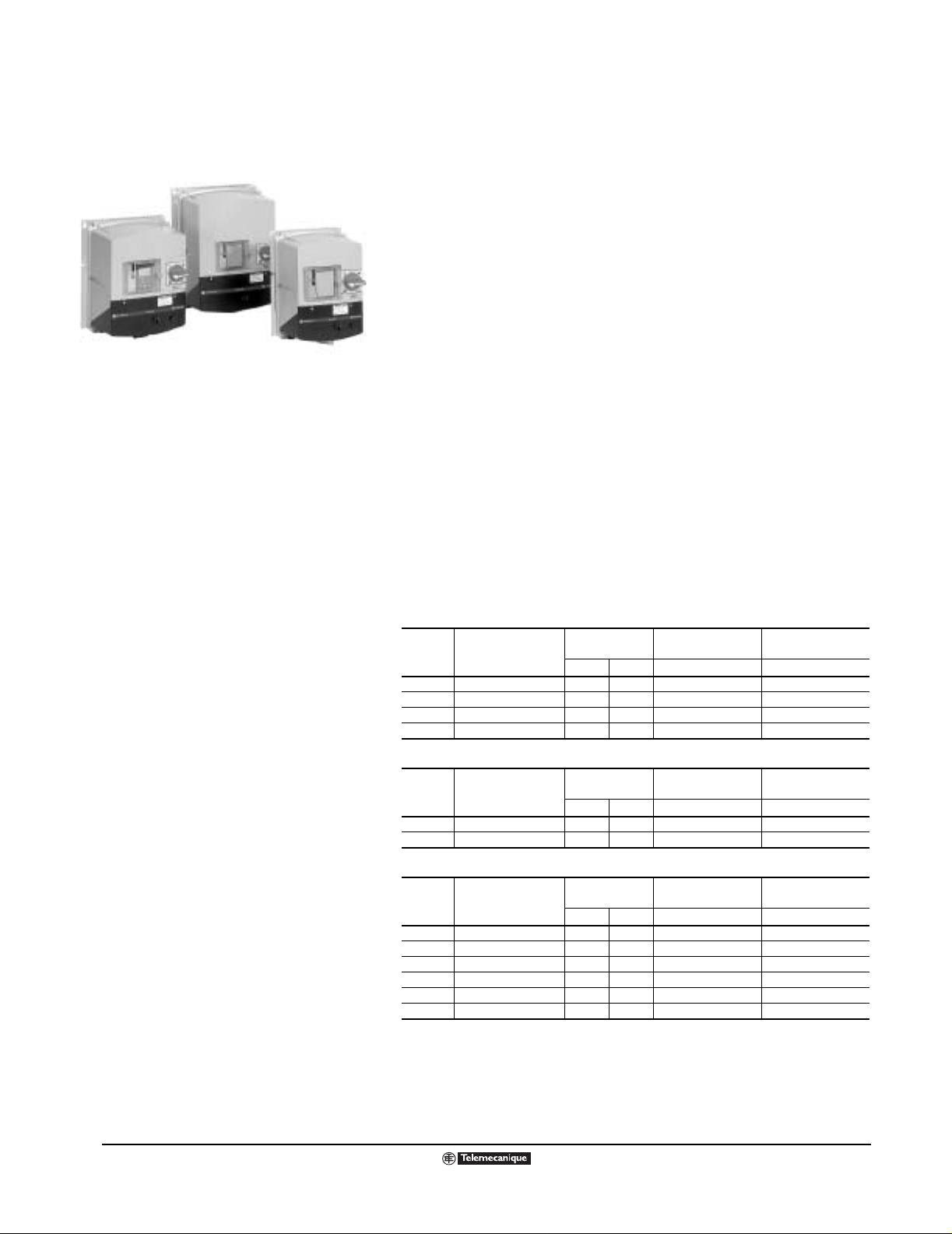
ATV58 TRX Type H Product Famil y
PRODUCT OVERVIEW
Altivar® 58 (ATV58) TRX AC driv e control lers off er superior p erformance in a
compact package. A TV58 TRX d rive contr ollers are d esign ed for modularity,
allowing you to customize the product to your exact needs. A variety of
multilingual operator interface options, I/O extension cards, communication
ATV58 TRX Fam10827R etouced.tif
cards, and hardware options are available.
ATV58 TRX drive controllers incorporate sensorless flux vector control for
three-phase asynchronous squirrel cage AC motors. They are available in
the follow ing confi gur ations:
•Type H
•Type FVC
•Type E
•Type F
•Type N
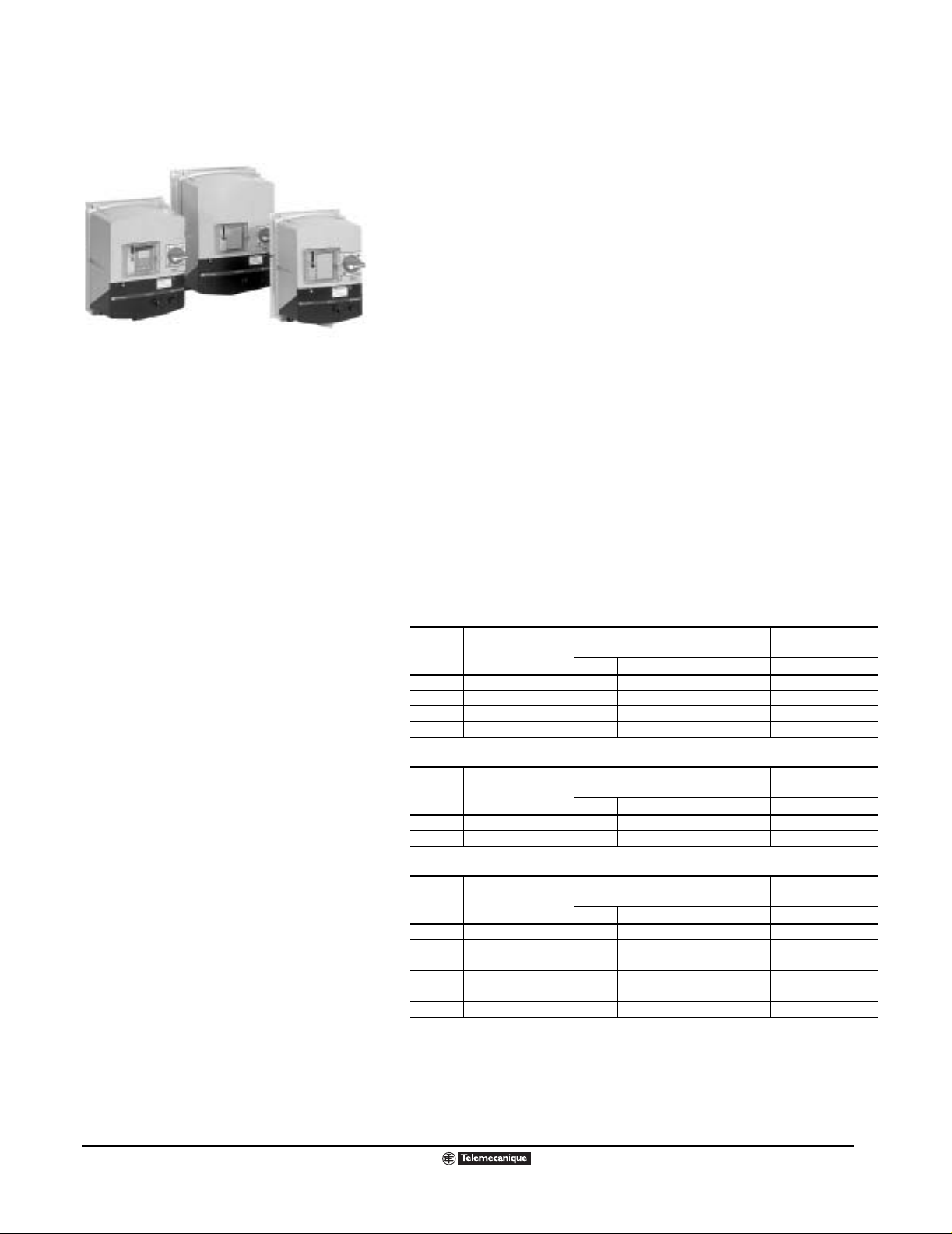
The ATV58 TRX Type H drive controller can be used in variable torque or
ATV58Family.tif
constant torque appl ications . Ea ch ATV58 TRX drive controlle r inco rporates
random switching frequency modulation to reduce motor noise. For variable
torque applications, the ATV58 TRX Type H controller includes features for
additional energy savings and quiet motor operation. For constant torque
applications, the ATV58 TRX Type H drive co ntrolle r f eature s a 1:100 sp eed
range with excellent torque performance through the entire range.
ATV58 Type FVC Product Family
ATV58 TRX Type E and Type F Product
Family
The ATV58 Type FVC drive controller offers the highest level of AC drive
performance. It is for use in constant torque applications requiring a 1:1000
speed range and torque at ze ro sp eed, or where respons e time to a change
in load is critical t o the application.
The Type H and Type FVC drive controlle rs ca n be m ounted in an encl osure
integrating othe r equipment, or wa ll-mounted using the o ptional conduit en try
kits.
TypeEF_Family.tif
The Type E, Type F, and Type N configurations offer a packaged product
ready to mount in a variety of environments.
• The ATV58 TRX Type E drive controller is Type 1 rated and has an
integrated output contactor.
• The ATV58 TRX Type F drive controller is Type 12 rated and contains
integrated line fuses.
• The ATV58 TRX Type N drive controller is Type 4/4X rated.
Each ATV58 TRX drive controller has an integrated RS-485 port. This port
has a variety of uses to fit your application requirements, including:
®
• Use as a multidrop Modbus
TypeN_Family.tif
• Connection for a keypad
port
• Connection for Magelis® termi n als
• Connection of PC or Pocket PC commissioning software
ATV58 TRX Type N Product Famil y
4
© 2000–2003 Schneider Electric All Rights Reserved
09/2003
Page 5

keypad photo.tif
Keypad Display (Left) and
Remote Mounting Kit (Right)
Altivar
®
58 TRX AC Drives
User Interface Options and Accessories
USER INTERFACE OPTIONS AND ACCESSORIES
Keypad Display
The operator keypad display can be mounted directly to the drive or
connected via a remote mountin g kit. It can be us ed to ope rate the drive, or
to display, configure, and adjust parameters. It can also be used to upload
and download configu rations.
OpInterfaceNew.tif
PowerSuite™ Software
®
PC Conn Kit.tif
This Windows
configure, and adjust parameters as well as upload and download
configurations . It can also be used to operate the driv e and vie w fau lt history .
The software may be used in a stand-alone mode to create or modify a
configuration and transfer it to an ATV58 TRX drive controller.
-based PC and Pocket PC software can be used to display,
PowerSuite Software
I/O Option Boards
IO_cards.tif
I/O Option Bo ards
A variety of optio n boards are a vailab le to e xpand th e I/O to match the n eeds
of the installation. The option boards mount internally without requiring
additional panel space.
Communication Option Boards
ComCards.tif
Individual communication cards are available to integrate the ATV58 TRX
drive controll er into many indus trial a nd building autom ati on co mmunication
protocols. Th ese all ow the user to control, a djust , and obt ain the status of an
ATV58 TRX drive controller. The communication card mounts internally
without requiring additional space.
Communication Option Boar ds
09/2003
© 2000–2003 Schneider Electric All Rights Reserved
5
Page 6

Altivar
®
58 TRX AC Drives
User Interface Options and Accessories
VentKits.tif
Ventilation Kits
CondEntKits.tif
Ventilation Kits
Ventilation fan kits are available for packaging the drive in a smaller
enclosure. The ve ntilation f an is p ow ered inte rnally and mo unts on top o f the
ATV58 TRX drive controller without requiring additional panel space.
Conduit Entrance Kits
Conduit entrance kits are available for wall-mount applications. The kits
attach to the bottom of the ATV58 TRX drive controller a nd are pro vide d with
multiple conduit knockouts.
Conduit Entrance Kits
Dynamic Braking Resistor Kits
Dynamic Braking Resistor Kits
Dynamic braking resistors packaged in Type 1 enclosures are available for
applications requiring fast cycle times. These kits mount separately.
DynBrake.tif
6
© 2000–2003 Schneider Electric All Rights Reserved
09/2003
Page 7

ATV58 TRX Type H Product Family
The ATV58 TRX series of adjustable
frequency AC drive controllers is a
Transparent Ready
TM
product line
providing extended functionality and an
extended hor sep o wer range for the ATV58
AC drive family. The ATV58 TRX series
includes an analog output, expanded
firmware capabilities, and a horsepower
range up to 500 hp. As a Transparent
Ready product equipped with an Ethernet
communication card, the ATV58 TRX
product line can be configured, controlled,
monitored, and diagnosed o ver an Ethernet
network with a standar d Web browser. No
special software or drivers are needed.
Altivar
®
58 TRX AC Drives
Type H Drive Controllers
ATV58 TRX TYPE H DRIVE CONTROLLERS
Features
The ATV58 TRX Type H drives are used for controlling three-phase
asynchronous motors ranging from:
• 1 to 350 hp CT (1 to 500 hp VT), 400/460 Vac, three-phase input
ATV58 TRX Fam10827Retouced.tif
• 0.5 to 7.5 hp CT (0.5 to 30 hp VT), 208/230 Vac, single-phase input
• 2 to 40 hp CT (2 to 50 hp VT), 208/230 Vac, three-phase input
The ATV58 TRX Type H drive controller uses the latest in AC drive
technology. Power modules are used on the entire product family. The
modules contain insulated gate bipolar transistors (IGBTs) to produce a
pulse width modulated (PWM) output waveform to the motor. The power
modules minimize part count and improve reliability.
The T y pe H drive controllers integrate third-ge neration senso rless flux vector
control for three-phase asynchronous squirrel cage AC motors. This allows
the drive cont roller to deliv er needed tor que with ex cellent dynamic response
over a wide speed range.
ATV58 TRX Type H drive controllers are capable of:
• Producing transient torque of 200% (±10%) of nominal motor torque for
2 seconds
• Producing transient torque of 170% (±10%) of nominal motor torque for
60 seconds
• Producing 160% of rated motor torque at 0.6 Hz with encoder feedback,
or at 1 Hz without tachometer or encoder feedback (open loop)
• Regulating rated motor speed within 1% without tachometer or encoder
feedbac k, or with in ±0.02 % with an enco der f eed bac k ci rcuit (op tion ca rd)
Each Type H drive controller has a selectable switching frequency that can
be adjusted to ma tch th e appli catio n requi rement s. The s wi tch ing fre quenc y
can be programmed to fold back in the event of excessive heat. The drive
controller reverts back to the programmed choi ce upon reac hing the normal
thermal state.
09/2003
In addition, each 1 5 hp (CT) to 5 0 hp (VT) 208/2 30 V ac Type H controller and
each 25 hp (CT) to 100 hp (VT) 400/460 V ac Ty pe H contro ller includ es a line
reactor integrated into the heatsink plenum. The line reactor improves
reliability and reduces input currents to the drive controller.
Most A TV58 TRX drive controllers are avai lable with an in tegrated EMC fil ter.
This filter reduc es conduct ed and rad iated em issions, and comp lies with IEC
product standards IEC 61800-3 and EN 61800-3 for drive controllers.
Compliance with these standards meets the requirements of the European
directive on EMC .
Configuration tools, operator interfaces, I/O extension options, and
communication options are shared throughout the product range.
© 2000–2003 Schneider Electric All Rights Reserved
7
Page 8

Altivar
®
58 TRX AC Drives
Type H Drive Controllers
Ratings
ATV58 TRX Type H drive controllers may be rated for constant torque (CT), variable torque (VT), and
variable torque low noise (VTLN) applications .
• CT applications usually require 100% of motor-rated torque through the entire speed range, high
transient torque capability, and speed regulation.
• VT applications , such as c entrifugal f ans an d centrifugal pu mps, do not require high tr ansient to rque
capability. Thi s typically al lows a d rive to be r ated f or additional h orsepow er and additio nal current as
compared to the constant torque rating.
• VTLN applications, such as centrifugal fans and centrifugal pumps, do not require high transient
torque capability. However , this r ating use s a higher s witch ing frequen cy f or quieter mo tor oper ation.
As a result, the drive ma y be rated at th e same horsepow er and current as the cons tant torque rating ,
particularly at large horsepower sizes.
The 125–500 hp driv e controll ers are listed in this cat alog with r atings typi cally use d for VT application s.
With proper selection, this range of controllers can also be used in CT applications, such as
compressors, conveyors, and extruders, where high performance is not required at low speeds. The
125–500 hp product ratings in this catalog are for applications that require 100% rated torque down to
6 Hz. If the application req uires more than 1 10% trans ient torque for on e minute , selec t the approp riate
horsepower product. For assistance with selecting the proper AC drive controller for constant torque
applications, co nsu lt your local Square D drives special is t.
Application information is also available in product data bulletin SC100, Adjustable Frequency
Controllers Application Guide, available at www.SquareD.com, or the NEMA Standards Publication:
Application Guide For AC Adjustable Speed Drive Systems.
▼ Refer to page 127 for a
complete list of catalog
numbers. An “X” in the
catalog number indicates that
the product does not hav e an
internal EMC filter. If an
internal EMC filter is required,
delete the “X” from the
catalog number.
■ When these drive controllers
are used with a single-phase
input, a line reactor (3%
minimum) must be used.
Ratings for ATV58 TRX Type H Constant Torque; 208/230 Vac, Single-Phase Input with 3-Phase Output;
Switching Frequency at 4 kHz
Frame Size
1 ATV58HU09M2ZU 0.37 0.5 2.3 3.1 42
1 ATV58HU18M2ZU 0.75 1 4.1 5.6 64
2 ATV58HU29M2ZU 1.5 2 7.8 10.6 107
2 ATV58HU41M2ZU 2.2 3 11 15.0 156
3 ATV58HU72M2ZU
4 ATV58HU90M2ZU
4 ATV58HD12M2ZU
Ratings for ATV58 TRX Type H Variable Torque, Low Noise; 208/230 Vac, Single-Phase Input with 3-Phase Output;
Switching Frequency: ATV58HU09M2–D12M2 at 8 kHz; ATV58HD16M2–D46M2 at 4 KHz
Frame Size
1 ATV58HU09M2ZU 0.37 0.5 2.5 2.8 42
1 ATV58HU18M2ZU 0.75 1 4.8 5.3 64
2 ATV58HU29M2ZU 1.5 2 7.8 8.6 107
2 ATV58HU41M2ZU 2.2 3 11 12.1 156
3 ATV58HU72M2ZU
4 ATV58HU90M2ZU
4 ATV58HD12M2ZU
6 ATV58HD16M2XZU
6 ATV58HD23M2XZU
7 ATV58HD28M2XZU
7 ATV58HD33M2XZU
7 ATV58HD46M2XZU
Drive Controller
Catalog Number
Drive Controller
Catalog Number
Motor Po wer
208/230 Vac
▼
kW HP A A W
■
■
■
3 4 13.7 18.6 160
4 5 18.2 24.8 176
5.5 7.5 24.2 32.9 204
Motor Power
208/230 Vac
▼
kWHPAAW
■
■
■
3 4 14.3 15.7 160
4 5 17.5 19.3 176
5.5 7.5 25.3 27.8 204
■
7.5 10 30.8 33.9 323
■
11 15 46.2 50.8 550
■
15 20 60 66.0 745
■
18.5 25 75 82.5 895
■
22 30 88 96.8 900
Rated
Output Current
Rated
Output Current
Transient
Output Current
Transient
Output Current
Total Dissipated
Power at Rated Load
Total Dissipated
Power at Rated Load
8
© 2000–2003 Schneider Electric All Rights Reserved
09/2003
Page 9

Altivar
Type H Drive Controllers
Ratings for ATV58 TRX Type H Constant Torque
208/230 Vac, 3-Phase Input with 3-Phase Output
Switching Frequency: ATV58HU29M2–D23M2 at 4 kHz, ATV58HD28M2–D46M2 at 2 kHz
®
58 TRX AC Drives
▼ Refer to page 127 for a
complete list of catalog
numbers. An “X” in the
catalog number indicates that
the product does not hav e an
internal EMC filter. If an
internal EMC filter is required,
delete the “X” from the
catalog number.
▼ Refer to page 127 for a
complete list of catalog
numbers. An “X” in the
catalog number indicates that
the product does not hav e an
internal EMC filter. If an
internal EMC filter is required,
delete the “X” from the
catalog number.
Frame Size
2 ATV58HU29M2ZU 1.5 2 7.8 10.6 107
2 ATV58HU41M2ZU 2.2 3 11 15 160
3 ATV58HU54M2ZU 3 4 13.7 18.6 190
3 ATV58HU72M2ZU 4 5 18.2 24.8 240
4 ATV58HU90M2ZU 5.5 7.5 24.2 32.9 255
4 ATV58HD12M2ZU 7.5 10 31 42.2 350
6 ATV58HD16M2XZU 11 15 47 63.9 745
6 ATV58HD23M2XZU 15 20 60 81.6 895
7 ATV58HD28M2XZU 18.5 25 75 102 900
7 ATV58HD33M2XZU 22 30 88 119.7 1030
7 ATV58HD46M2XZU 30 40 116 157.8 1315
Ratings for ATV58 TRX Type H Variable Torque
208/230 Vac, 3-Phase Input with 3-Phase Output
Drive Controller
Catalog Number
Motor Power
208/230 V
▼
kW HP A A W
Rated
Output Current
Transient
Output Current
Total Dissipated
Power at Rated Load
Switching Frequency: ATV58HU29M2–D23M2 at 4 kHz, ATV58HD28M2–D46M2 at 2 kHz
Frame Size
2 ATV58HU29M2ZU 1.5 2 7.5 8.3 107
2 ATV58HU41M2ZU 2.2 3 10.6 11.7 158
3 ATV58HU54M2ZU 3 4 14.3 15.7 190
3 ATV58HU72M2ZU 4 5 16.7 18.4 198
4 ATV58HU90M2ZU 5.5 7.5 24.2 26.6 235
4 ATV58HD12M2ZU 7.5 10 30.8 33.9 323
6 ATV58HD16M2XZU 11 15 46.2 50.1 550
6 ATV58HD16M2XZU 15 20 60 66 745
6 ATV58HD23M2XZU 18.5 25 75 82.5 895
7 ATV58HD28M2XZU 22 30 88 96.8 900
7 ATV58HD33M2XZU 30 40 116 127.6 1030
7 ATV58HD46M2XZU 37 50 143 157.3 1315
Drive Controller
Catalog Number
Motor Power
208/230 Vac
▼
kW HP A A W
Rated
Output Current
Transient
Output Current
Total Dissipated
Power at Rated Load
▼ Refer to page 127 for a
complete list of catalog
numbers. An “X” in the
catalog number indicates that
the product does not hav e an
internal EMC filter. If an
internal EMC filter is required,
delete the “X” from the
catalog number.
09/2003
Ratings for ATV58 TRX Type H Variable Torque, Low Noise
208/230 Vac, 3-Phase Input with 3-Phase Output
Switching Frequency: ATV58HU29M2–D23M2 at 8 kHz, ATV58HD28M2–D46M2 at 4 kHz
Frame Size
2 ATV58HU29M2ZU 1.5 2 7.5 8.3 107
2 ATV58HU41M2ZU 2.2 3 10.6 11.7 158
3 ATV58HU54M2ZU 3 4 14.3 15.7 190
3 ATV58HU72M2ZU 4 5 16.7 18.4 198
4 ATV58HU90M2ZU 5.5 7.5 24.2 26.6 235
4 ATV58HD12M2ZU 7.5 10 30.8 33.9 323
6 ATV58HD16M2XZU 11 15 46.2 50.1 745
6 ATV58HD23M2XZU 15 20 60 66 890
7 ATV58HD28M2XZU 18.5 25 75 82.5 980
7 ATV58HD33M2XZU 22 30 88 96.8 975
7 ATV58HD46M2XZU 30 40 116 127.6 1215
Drive Controller
Catalog Number
Motor Power
208/230 V
▼
kW HP A A W
Rated Output
Current
Transient
Output Current
Total Dissipated
Power at Rated Load
© 2000–2003 Schneider Electric All Rights Reserved
9
Page 10

Altivar
®
58 TRX AC Drives
Type H Drive Controllers
Ratings for ATV58 TRX Type H Constant Torque
400 /460 Vac, 3-Phase Input with 3-Phase Output
Switching Frequency: ATV58HU18N4–D46N4 at 4 kHz, ATV58HD54N4–D79N4 at 2 kHz
▼ Refer to page 127 for a
complete list of catalog
numbers. An “X” in the
catalog number indicates that
the product does not hav e an
internal EMC filter. If an
internal EMC filter is required,
delete the “X” from the
catalog number.
▼ Refer to page 127 for a
complete list of catalog
numbers. An “X” in the
catalog number indicates that
the product does not hav e an
internal EMC filter. If an
internal EMC filter is required,
delete the “X” from the
catalog number.
Frame Size
2 ATV58HU18N4ZU 0.75 1 2.3 3.1 57
2 ATV58HU29N4ZU 1.5 2 4.1 5.6 97
2 ATV58HU41N4ZU 2.2 3 5.8 7.9 120
3 ATV58HU54N4XZU 3 4 7.8 10.6 170
3 ATV58HU72N4XZU 4 5 10.5 14.3 210
3 ATV58HU90N4XZU 5.5 7.5 13 17.7 295
4 ATV58HD12N4XZU 7.5 10 17.6 23.9 360
4 ATV58HD16N4XZU 11 15 24.2 32.9 480
5 ATV58HD23N4XZU 15 20 33 44.9 590
6 ATV58HD28N4XZU 18.5 25 40.7 55.4 421
6 ATV58HD33N4XZU 22 30 48.4 65.8 491
6 ATV58HD46N4XZU 30 40 66 89.8 625
7 ATV58HD54N4XZU 37 50 79.2 107.7 677
7 ATV58HD64N4XZU 45 60 93.5 127.2 837
7 ATV58HD79N4XZU 55 75 115.5 157.1 1090
Ratings for ATV58 TRX Type H Variable Torque, Low Noise
400/460 Vac, 3-Phase Input with 3-Phase Output
Drive Controller
Catalog Number
Motor Power
400/460 Vac
▼
kWHPAAW
Rated
Output Current
Transient
Output Current
Total Dissipated
Power at Rated Load
Switching Frequency: ATV58HU18N4–D46N4 at 8 kHz, ATV58HD54N4–D79N4 at 4 kHz
Frame Size
2 ATV58HU18N4ZU 0.75 1 2.1 2.3 57
2 ATV58HU29N4ZU 1.5 2 3.4 3.7 97
2 ATV58HU41N4ZU 2.2 3 4.8 5.3 119
3 ATV58HU54N4XZU — 5 7.6 8.4 209
3 ATV58HU72N4XZU — 7.5 11 12.1 291
3 ATV58HU90N4XZU — 10 14 15.4 352
4 ATV58HD12N4XZU — 15 21 23.1 472
4 ATV58HD16N4XZU — 20 27 29.7 584
5 ATV58HD23N4XZU — 25 34 37.4 654
6 ATV58HD28N4XZU 18.5 25 34 37.4 502
6 ATV58HD33N4XZU 22 30 40 44 584
6 ATV58HD46N4XZU 30 40 52 57.2 714
7 ATV58HD54N4XZU 37 50 65 71.5 732
7 ATV58HD64N4XZU 45 60 77 84.7 904
7 ATV58HD79N4XZU 55 75 96 105.6 1183
Drive Controller
Catalog Number
Motor Power
400/460 Vac
▼
kWHPAAW
Rated
Output Current
Transient
Output Current
Total Dissipated
Power at Rated Load
10
© 2000–2003 Schneider Electric All Rights Reserved
09/2003
Page 11

Altivar
®
58 TRX AC Drives
Type H Drive Controllers
Ratings for ATV58 TRX Type H Variable Torque
400/460 Vac, 3-Phase Input with 3-Phase Output
Switching Frequency: ATV58HU18N4–D23N4 at 8 kHz, ATV58HD28N4-D46N4 at 4 kHz, ATV58HD54N4–C33N4X at 2 kHz
▼ Refer to page 127 for a
complete list of catalog
numbers. An “X” in the
catalog number indicates that
the product does not hav e an
internal EMC filter.
■ The ATV58HD28N4 is rated
for 8 kHz operation at 25 hp.
Frame Size
2 ATV58HU18N4ZU 0.75 1 2.1 2.3 57
2 ATV58HU29N4ZU 1.5 2 3.4 3.7 97
2 ATV58HU41N4ZU 2.2 3 4.8 5.3 119
3 ATV58HU54N4XZU 3 4 6.2 6.8 170
3 ATV58HU72N4XZU 4 5 7.6 8.4 209
3 ATV58HU90N4XZU 5.5 7.5 11 12.1 291
4 ATV58HD12N4XZU 7.5 10 14 15.4 352
4 ATV58HD16N4XZU 11 15 21 23.1 472
5 ATV58HD23N4XZU 15 20 27 29.7 584
6 ATV58HD28N4XZU
6 ATV58HD28N4XZU 22 30 40 44 618
6 ATV58HD33N4XZU 30 40 52 57.2 713
6 ATV58HD46N4XZU 37 50 65 71.5 770
7 ATV58HD54N4XZU 45 60 77 84.7 987
7 ATV58HD64N4XZU 55 75 96 105.6 1075
7 ATV58HD79N4XZU 75 100 124 136.4 1439
8 ATV58HC10N4XZU 90 125 156 172 2250
9 ATV58HC13N4XZU 110 150 180 198 2750
9 ATV58HC15N4XZU 132 200 240 264 3300
9 ATV58HC19N4XZU 160 250 302 332 4000
10 ATV58HC23N4XZU 200 300 361 397 5000
10 ATV58HC25N4XZU 220 350 414 455 5500
10 ATV58HC28N4XZU 250 400 477 525 6250
10 ATV58HC31N4XZU 280 450 515 567 7000
10 ATV58HC33N4XZU 315 500 590 649 7875
Drive Controller
Catalog Number
Motor Power
400/460 Vac
▼
kW HP A A W
■
18.5 25 34 37.4 474
Rated
Output Current
Transient
Output Current
Total Dissipated
Power at Rated Load
09/2003
© 2000–2003 Schneider Electric All Rights Reserved
11
Page 12
Altivar
®
58 TRX AC Drives
Type E Drive Controllers
ATV58 TRX Type E Product Family
ATV58 TRX TYPE E DRIVE CONTROLLERS
The ATV58 TRX family of adjustable-frequency AC drive controllers is used
to control three-phase async hronous motors . The ATV58 TRX T ype E model
contains an ATV58 TRX T ype H driv e controller p ackaged i n a compact , T y pe
1 enclosure. It is for use in mechanic al ro om s , OEM eq uipment, and fac tory
floor applications . Th e f oll owi ng Type E drive controller mod els are a v aila b le:
ATV58NEMAb_w no back.tif
• 1 to 7½ hp (0.75 to 5.5 kW), 400/460 Vac, three-phase input
• ½ to 3 hp (0.37 to 2.2 kW), 200/240 Vac, single-phase input
• 2 to 3 hp (1.5 to 2.2 kW), 200/240 Vac, three-phase input
Each ATV58 TRX Type E drive controller contains:
• A GV2 manual motor starter, ATV58 TRX drive controller, and an output
contactor
• A three-position selector switch wired for “RUN FORWARD”
• A manual speed potentiometer mounted on the front of the enclosure
• Space for two additional 16-mm operators
• Four conduit openings that are closed with plugs
• A transparent plastic door for viewing the status LEDs and a separatelysupplied keypad
All ATV58 TRX communication and I/O options can be used in the Type E
controllers. The Type E drive controllers c an be used on constant or vari able
torque applications. The ratings are shown in the tables below.
200 Vac -10% / 240 Vac +10% at 50/60 Hz ±5%, Single-Phase Input with 3-Phase Output
Rated
Frame
Size
1 ATV58EU09M2ZU 0.37 0.5 2.3 3.1
1 ATV58EU18M2ZU 0.75 1 4.1 5.6
2 ATV58EU29M2ZU 1.5 2 7.8 10.6
3 ATV58EU41M2ZU
200 Vac -10% / 240 Vac +10% at 50/60 Hz ±5%, 3-Phase Input with 3-Phase Output
Frame
Size
2 ATV58EU29M2ZU 1.5 2 7.8 10.6
3 ATV58EU41M2ZU 2.2 3 11 15
400 Vac -10% / 460 Vac +10% at 50/60 Hz ±5%, 3-Phase Input with 3-Phase Output
Frame
Size
2 ATV58EU18N4ZU 0.75 1 2.3 3.1
2 ATV58EU29N4ZU 1.5 2 4.1 5.6
2 ATV58EU41N4ZU 2.2 3 5.8 7.9
3 ATV58EU54N4ZU 3 – 7.8 10.6
3 ATV58EU72N4ZU 4 5 10.5 14.3
3 ATV58EU90N4ZU 5.5 7.5 13 17.7
▲ For dimensions, see page 122; for wiring diagrams, see pages 109 and 110.
▼ Power indicated is for a switching frequency between 0.5 and 4 kHz, and at steady state. For switching
◆ For 60 seconds.
■ A line reactor (3% minimum) must be used with this drive controller.
Drive Controller
▲
Catalog Number
Drive Controller
▲
Catalog Number
Drive Controller
▲
Catalog Number
frequency between 8 and 16 kHz, use the next largest size drive control ler . (F or examp le, f or 2 hp, ord er driv e
controller ATV58EU41M2ZU.) If the duty cycle (t hat is, the drive controller run t i me) does not exceed 60% (36
second maximum for a 60 second cycle), this is not necessary.
Motor Power
kW HP A A
■
2.2 3 11 15
Motor Power
kW HP A A
Motor Power
kW HP A A
▼
Output Current
Rated
▼
Output Current
Rated
▼
Output Current
Transient
Output Current
Transient
Output Current
Transient
Output Current
◆
◆
◆
12
© 2000–2003 Schneider Electric All Rights Reserved
09/2003
Page 13
Altivar
®
58 TRX AC Drives
Type F Drive Controllers
ATV58 TRX TYPE F DRIVE CONTROLLERS
The ATV58 TRX family of adjustable-frequency AC drive controllers is used
to control three-phase asynchronous motors. ATV58 TRX Type F models
contain an ATV58 TRX Type H drive controller packaged in a compact Type
12 enclosure. They are for use in mech anical rooms, OEM equipment, and
factory floor applications requiring a local load break switch and input line
ATV58NEMAb_w no back.tif
fusing. Th e following models are available:
• 1 to 7.5 hp (0.75 to 5.5 kW), 400/460 Vac, three-phase input
• ½ to 3 hp (0.37 to 2.2 kW), 200/240 Vac, single-phase input
• 2 to 3 hp (1.5 to 2.2 kW), 200/240 Vac, three-phase input
ATV58 TRX Type F Product Family
Each ATV58 TRX Type F drive controller contains:
• A Vario load break switch, input li ne fuses, and an ATV58 TRX drive
controller
• Start Stop push buttons
• A manual speed potentiometer mounted on the front of the enclosure
• Space for one additional 16-mm operator
• Four conduit openings that are closed with plugs
• A transparent plastic door to allow viewing of status LEDs and a
separately supplied keypad
All ATV58 TRX communications and I/O options can be used in the Type F
drive controllers. The Type F drive controllers can be used on constant or
variable torque applications. The ratings are shown in the tables below.
200 Vac -10% / 240 Vac +10% at 50/60 Hz ±5%, Single-Phase Input with 3-Phase Output
Rated
Frame
Size
1 ATV58EU09M2FZU 0.37 0.5 2.3 3.1
1 ATV58EU18M2FZU 0.75 1 4.1 5.6
2 ATV58EU29M2FZU 1.5 2 7.8 10.6
3 ATV58EU41M2FZU
200 Vac -10% / 240 Vac +10% at 50/60 Hz ±5%, 3-Phase Input with 3-Phase Output
Frame
Size
2 ATV58EU29M2FZU 1.5 2 7.8 10.6
3 ATV58EU41M2FZU 2.2 3 11 15
400 Vac -10% / 460 Vac +10% at 50/60 Hz ±5%, 3-Phase Input with 3-Phase Output
Frame
Size
2 ATV58EU18N4FZU 0.75 1 2.3 3.1
2 ATV58EU29N4FZU 1.5 2 4.1 5.6
2 ATV58EU41N4FZU 2.2 3 5.8 7.9
3 ATV58EU54N4FZU 3 – 7.8 10.6
3 ATV58EU72N4FZU 4 5 10.5 14.3
3 ATV58EU90N4FZU 5.5 7.5 13 17.7
▲ For dimensions, see page 122; for wiring diagrams, see pages 111 and 112.
▼ Power indicated is for a switching frequency between 0.5 and 4 kHz, and at steady state. For switching
◆ For 60 seconds.
■ A line reactor (3% minimum) must be used with this drive controller.
Drive Controller
▲
Catalog Number
Drive Controller
▲
Catalog Number
Drive Controller
▲
Catalog Number
frequency between 8 and 1 6 kH z, use t he n e xt l arge st size drive controller. (For example, for 2 hp, order drive
controller A TV58EU41M2F ZU.) If the duty cycle (that is , the drive co ntroller run time) does not e xceed 60% (36
second maximum for a 60 second cycle), this is not necessary.
Motor Pow er
kW HP A A
■
2.2 3 11 15
Motor Pow er
kW HP A A
Motor Pow er
kW HP A A
▼
Output Current
Rated
▼
Output Current
Rated
▼
Output Current
Transient
Output Current
Transient
Output Current
Transient
Output Current
◆
◆
◆
09/2003
© 2000–2003 Schneider Electric All Rights Reserved
13
Page 14

Altivar
®
58 TRX AC Drives
Type N Drive Controllers
ATV58 TRX Type N Pr odu ct F am il y
ATV58 TRX TYPE N DRIVE CONTROLLERS
The ATV58 TRX family of adjustable-frequency AC drive controllers is used
to control three-phase asynchronous motors .The ATV58 TRX T ype N models
contain an ATV58 TRX Type H drive controller packaged in a Type 4/4x
stainless steel enc losure . The y a re for use in food and b e v er age wa sh-do w n
applications. The Type N drive controller was tested f or co rrosion resis tance
ATV58NEMA4Xb_w no back.tif
per UL-50 and exceeds this standard. The UL-50 corrosion test was
conducted using ASTM B117-1985.
The following models are available:
• 1 to 10 hp (0.75 to 7.5 kW), 400/460 Vac, 3-phase input.
• ½ to 3 hp (0.37 to 2.2 kW), 208/230 Vac, single-phase input.
• ½ to 5 hp (0.37 to 4.0 kW), 208/230 Vac, 3-phase input.
Each Type N driv e co ntroll er is furnished with f o ur cond uit open ings th at are
closed with Type 4/4x plugs. The drive is available with a keypad mounted
behind a transparen t boot to allo w view ing and oper ation of the k eyp ad while
maintaining the Type 4/4x rating. If a keypad is not required, a closing plate
can be installed to maintain the Type 4/4x rating. All ATV58 TRX
communication and I/O options can be used in the Type N controllers. The
Type N drive controllers can be used on constant or variable torque
applications. The ratings are shown in the tables below.
208 to 230 Vac, Single-Phase Input with 3-Phase Output
Rated Output
Frame
Size
1 ATV58NU09M2• 0.37 0.5 2.3 3.1
1 ATV58NU18M2• 0.75 1 4.1 5.6
2 ATV58NU29M2• 1.5 2 7.8 10.6
2ATV58NU41M2•■2.2 3 11 15
208 to 230 Vac, 3-Phase Input with 3-Phase Output
Frame
Size
2 ATV58NU29M2• 1.5 2 7.8 10.6
2ATV58NU41M2• 2.2311 15
3 ATV58NU54M2• 3 – 13.7 18.6
3 ATV58NU72M2• 4 5 18.2 24.7
400 to 460 Vac, 3-Phase Input with 3-Phase Output
Frame
Size
2 ATV58NU18N4• 0.75 1 2.3 3.1
2 ATV58NU29N4• 1.5 2 4.1 5.6
2 ATV58NU41N4• 2.2 3 5.8 7.9
3 ATV58NU54N4• 3 – 7.8 10.6
3 ATV58NU72N4• 4 5 10.5 14.3
3 ATV58NU90N4• 5.5 7.5 13 17.7
4 ATV58ND12N4• 7.5 10 17.6 24
▲ Complete the catalog number by entering K U f or ATV58 Type N drive controllers with factory-installed keypad,
❋ Power indicated is for a switching frequency between 0.5 and 4 kHz, and at steady state. For switching
◆ For 60 seconds.
■ When these drive controllers are used with a single-phase input, a line reactor (3% minimum) must be used.
Drive Controller
Catalog Number
Drive Controller
Catalog Number
Drive Controller
Catalog Number
or ZU for controllers without a fa ctory-installed keypad. F or dimensions, see page 122 ; for wiring diagram s, see
page 108.
frequency between 8 and 16 kHz, derate the drive controller by one horsepower size (for example, for ½ hp,
order drive controller ATV58NU18M2). If the duty cycle (i.e., drive controller run time) does not exceed 60%
(36 second maximum for a 60 second cycle), derating is not required for operation above 8 kHz.
Motor Power
▲
kW HP A A
Motor Power
▲
kW HP A A
Motor Power
▲
kW HP A A
❋
Current
Rated Output
❋
Current
Rated
❋
Output Current
Transient Output
◆
Current
Transient Output
◆
Current
Transient Output
◆
Current
14
© 2000–2003 Schneider Electric All Rights Reserved
09/2003
Page 15

ATV58 Type FVC Product Family
The ATV58 Type FVC series of adjustable
frequency AC drive controllers is a
Transparent ReadyTM product line
providing extended functionality. The
A TV58 T ype FVC series includes an analog
output, expanded firmware capabilities,
and a horsepower range up to 75 hp. As a
Transparent Ready product equipped with
an Ethernet communication card, the
ATV58 Type FVC product line can be
configured, controlled, monitored, and
diagnosed ov er an Ethernet network with a
standard Web br owser. No sp ecial software
or drivers are needed.
Altivar
®
58 TRX AC Drives
Type FVC Drive Controllers
ATV58 TYPE FVC DRIVE CONTROLLERS
Features
The ATV58 Type FVC family of adjusta ble freque ncy A C drive con trollers are
used for controlling three-phase asynchronous motors ranging from
ATV 58F ami l y.ti f
1 to 75 hp (constant torque), 400/460 Vac, 3-phase input.
The ATV58 TRX operator interfaces, configuration tools, I/O extension
options, and communication options are shared throughout the product
range, except the general purpose option card which is not for use with the
ATV58 Type FVC controllers.
The ATV58 Type FVC driv e con troller uses the l atest in A C driv e te chnol og y.
Intelligent Power Modul es ( IPMs ) are use d on th e en tire prod uct family. The
IPMs contain insulated gate bipolar transistors (IGBTs) to produce a pulse
width modulated (PWM) output waveform to the motor. IPMs minimize part
count and improve reliability.
The ATV58 Type FVC drive controller integrates fourth-generation
sensorless flux vector control for 3-phase asynchronous squirrel cage AC
motors. This allows the drive controller to deliver needed torque with
excellent dynamic response over a wide speed range.
ATV58 Type FVC drive controllers are capable of:
• Producing transi ent torque of 2 00% (typical value ±10%) of nominal m otor
torque for 2 seconds
• Producing transi ent torque of 1 70% (typical value ±10%) of nominal m otor
torque for 60 seconds
• Producing 160% of rated motor torque at 0 Hz with encoder feedback
(closed loop) or at 0 .5 Hz w it hou t ta ch om ete r or enc od er feedback (open
loop)
• Regulating rated motor speed within 1% without tachometer or encoder
feedback or within ±0.01% with an encoder feedback circuit
09/2003
Every Type FVC drive c ontroller h as selectab le s w itching freque ncy that c an
be adjusted to match the appli cation nee ds. The swi tching freq uency can be
programmed to f ol d-bac k in the e vent of ex cess iv e h eat. Th e d rive contro ller
reverts back to the programmed choice upon reaching the normal thermal
state.
In addition, each 25 hp to 75 hp 40 0/46 0 Vac dri ve controller include s a li ne
reactor integrated into the heatsink plenum. This line reactor improves
product reliability and reduces input currents to the drive controller.
Every ATV58 Type FVC drive controller is supplied with an integrated EMC
filter. This filter reduces conducted and radiated emissions, and complies
with IEC product standards IEC 61800-3 and EN 61800-3 for drive
controllers. Compli ance wi th the se st and ards mee ts the req uirements of th e
European directive on EMC.
© 2000–2003 Schneider Electric All Rights Reserved
15
Page 16

Altivar
®
58 TRX AC Drives
Type FVC Drive Controllers
Applications
The ATV58 Type FVC product is recommended in place of the ATV58 TRX Type H drive controllers in
the following applications:
• Applications that require encoder feedback and the installation of an I/O extension card or a
communication card
• Applications that require PID regulation of a process loop
• Applications requiring improved open loop torque performance at low speed
• Applications requiring high torque performance at low speed with encoder feedback
• Applications requiring holding torque at zero speed
The A TV58 Type FVC product has th e follo wing hardw are not supplied with the ATV58 TRX Type H base
product:
• Differential analog input, +/- 10 Vdc (+10 Vdc supplied from drive)
• RS422 encoder input, 5 V (max. frequency input: 200 kHz)
• Encoder power supply (5 V, 200 mA)
• A keypad is supplied with the drive controller
The A TV58 Type FVC product has the follow ing software f eatures not supplied with the A TV58 TRX Type
H base product:
• Faster motor control algorithm in open loop and closed loop
• PID regulator with trim input
• Motor pre-fluxing options; continuous or by logic input
• Ability to customize the shape of the acceleration and deceleration ramps. Selectable acceleration
and deceleration ram p inc rem ents are 0.1seconds or 0.01 seconds.
• Ability to use +/- speed trim around a speed reference input
• PI and IP mode of operation f or matching init ial response tim e vs.ability to sup press speed o versh oot
• Variable torque macro has been removed. No variable torque ratings.
The ATV58 Type FVC drive controller is rated for Constant Torque (CT) applications. Constant To rque
applications usually require motor-rated torque through the entire speed range, high transient torque
capability, and precise speed regulation.
16
© 2000–2003 Schneider Electric All Rights Reserved
09/2003
Page 17

Altivar
Type FVC Drive Controllers
Ratings
Ratings for ATV58 Type FVC Constant Torque
400 /460 Vac, 3-Phase Input with 3-Phase Output
Switching Frequency: ATV58FHU18N4–D46N4 at 4 kHz, ATV58FHD54N4–D79N4 at 2 kHz
®
58 TRX AC Drives
Frame Size
2 ATV58FHU18N4KU 0.75 1 2.3 3.1 57
2 ATV58FHU29N4KU 1.5 2 4.1 5.6 97
2 ATV58FHU41N4KU 2.2 3 5.8 7.9 120
3 ATV58FHU54N4KU 3 4 7.8 10.6 170
3 ATV58FHU72N4KU 4 5 10.5 14.3 210
3 ATV58FHU90N4KU 5.5 7.5 13 17.7 295
4 ATV58FHD12N4KU 7.5 10 17.6 23.9 360
4 ATV58FHD16N4KU 11 15 24.2 32.9 480
5 ATV58FHD23N4KU 15 20 33 44.9 590
6 ATV58FHD28N4KU 18.5 25 40.7 55.4 421
6 ATV58FHD33N4KU 22 30 48.4 65.8 491
6 ATV58FHD46N4KU 30 40 66 89.8 625
7 ATV58FHD54N4KU 37 50 79.2 107.7 677
7 ATV58FHD64N4KU 45 60 93.5 127.2 837
7 ATV58FHD79N4KU 55 75 115.5 157.1 1090
Drive Controller
Catalog Number
Motor Power
400/460 Vac
kW HP A A W
Rated
Output Current
Transient
Output Current
Total Dissipated
Power at Rated Load
09/2003
© 2000–2003 Schneider Electric All Rights Reserved
17
Page 18

Altivar
®
58 TRX AC Drives
Terminal Locations for Type H and Type FVC Drives
TERMINAL LOCATIONS FOR ATV58 TRX TYPE H AND TYPE FVC DRIVES
NOTE: These illustrations show
the locations of the majo r terminal
groups.
FrameSize1.eps
FrameSize23.eps
FrameSize45.eps
Control Terminals
Frame Size 1 Frame Sizes 2 and 3
Ground Terminal
Power Terminals
FrameSize6.eps
Ground Terminal
Control Terminals
Power Terminals
Control Terminals
Control Terminals
Ground Terminal
Frame Sizes 4 and 5
Power Terminals
Control Terminals
FrameSize7.eps
Frame Size 6
18
© 2000–2003 Schneider Electric All Rights Reserved
Power Terminals
Ground Terminal
Power Terminals
Ground Terminal
Frame Size 7
09/2003
Page 19

Terminal Locations for Type H and Type FVC Drives
TERMINAL LOCATIONS FOR ATV58 TRX TYPE H DRIVES
Altivar
®
58 TRX AC Drives
Dwg1Conn.eps
DANGER
Control Terminals
Ground Terminals
T/L3
S/L2
R/L1
PB PA PC
P0
R/L1
S/L2
T/L3 U/T1
PA
V/T2 W/T3
Power Terminals
PA PO
Ground Terminals
Frame Size 8 Frame Size 9
PB U/T1 V/T2 W/T3
PC
Dwg2Conn.eps
Control Terminals
Power Terminals
09/2003
R/L1 S/L2 T/L3
PC
PB PO
Power Terminals
Frame Size 10
Ground Terminals
PA
PA
Dwg3Conn.eps
Control Terminals
U/T1
V/T2
W/T3
© 2000–2003 Schneider Electric All Rights Reserved
19
Page 20

Altivar
®
58 TRX AC Drives
Description of Power Terminals
ATV58*U09M2 - U18M2
L1 L2 + – U V W
ATV58*U29M2 - D12M2
ATV58*U18N4 - D23N4
L1 L2 L3 PA PB U V W
ATV58*D16M2 - D46M2
ATV58*U28N4 - D79N4
L1 L2 L3 PA PB U V W
ATV58HC10N4X
L1 L2 L3
ATV58HC13N4X–C19N4X
L1
L2 L3
PA
(+)
PC
(–)
PA
+
U
–
PC
PA
(–)
(+)
VW
UV
W
PowrTermsNew.eps
DESCRIPTION OF POWER TERMINALS
As shown in the drawing to the left, the ATV58 TRX power term inal
arrangements differ from model to model. The locations of the power
terminals are shown on pages 18–19. The following tables describe the
characteristics of the power terminals and list maximum wire sizes and
tightening torques for the various ATV58 TRX models.
Function of Power Terminals
Terminal Function Found On
Ground terminal (2 provided on some mod els). All A T V58 TRX models.
L1
L2
L3 All models except U09M2• and U18M2•
+
–
PA
PB
U
V
W
K13
K14
Input power.
Connection for DB module. Models U09M2• and U18M2•.
Connection for DB resistor.
Output connections to motor. All models.
N.O. auxiliary contact on controller’s output
contactor. Maximum rating is 10 A at 600 Vac.
All models.
All models except U09M2•, U18M2•, and
C10N4–C33N4.
ATV58EU09M2ZU – U90N4FZ4.
ATV58HC23N4X–C33N4X
L2 L3
L1
PC
(–)
ATV58Exxxxxxx
1
J2B
4
J2A
L3
ATV58EU09M2ZU and ATV58EU18M2ZU
(single-phase input only)
1
J2B
*
J2A
L3
* L3 is not used
PA
PA
UV
(+)
2345678
V W K13K14 PA
U
32
1
L2 L1
2345678
V W K13K14 +
U
32
1
L2 L1
PB
W
–
ATV58 TRX Power Terminals
Power Terminal Wire Size and Torque
Type FVC, Type H, and Type N Models
U09M2, U18M2 14 (1.5) 5.0 (0.55)
U29M2, U41M2, U18N4, U29N4, U41N4 8 (6) 7.5 (0.85)
U54M2, U72M2, U54N4, U72N4, U90N4 8 (6) 7.5 (0.85)
U90M2, D12M2, D12N4, D16N4, D23N4 6 (10) 20 (2.25)
D16M2, D23M2, D28N4, D33N4, D46N4 2/0 (35) 88 (10)
D28M2, D33M2, D46M2, D54N4, D64N4, D79N4 4/0 (70) 170 (19)
C10N4X–C19N4X 500 MCM 375 (42)
C23N4X–C33N4X Supply crimp style lugs to fit selected wire size.
Maximum Wire Size
AWG (mm2)
Type E and Type F Models
All models 10 (4) 5.0 (0.55)
◆ 75 °C copper.
◆
Torque
lb-in (N•m)
CONDUIT CONNECTIONS FOR TYPE E AND TYPE F
DRIVE CONTROLLERS
The ATV58 TRX Type E and Type F drive controllers are furnished with four
conduit openings at the bottom of the device. The conduit openings are
closed with Type 1 rated plugs. The holes are intended for input and output
power wiring, control wiring, and connection to e xternal components su ch as
DB resistors or line reactors . To m aintain the enclosure rating, do not remo ve
the plugs from unused conduit holes. Conduit holes are pre-drilled for the
conduit listed in the table belo w.
Type E and Type F Models Conduit Hole Size C onduit Size Hub Catalog No.
ATV58EU09M2ZU
ATV58EU18M2ZU
All other ATV58 Type E and Type F
Drive Controllers
7/8 inch 1/2 inch 25211-16102
1 and 3/32 inch 3/4 inch 25211-24102
20
© 2000–2003 Schneider Electric All Rights Reserved
Flexible conduit must be used up to the drive controller to facilitate removal
of the terminal block cover. A minimum of 2 feet is recommended.
09/2003
Page 21
R2A
R2C
AO1
COM
R1A
R1B
R1C
AI1
+10
ATV58 TRX Control Terminals
Altivar
®
58 TRX AC Drives
Description of Control Terminals
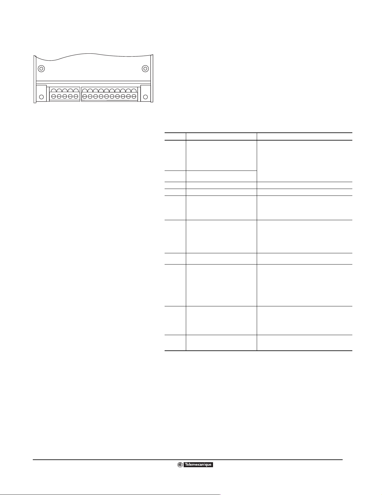
DESCRIPTION OF CONTROL TERMINALS
All ATV58 TRX Type E, Type F, Type H, and Type N models have the same
control terminals, sho wn in th e figu re to the left. The locations of the control
Terminal.eps
LI1
LI2
AI2
LI3
LI4
+24
S
termin als varies from model to model as shown on pa ges 18 and 19.
The control terminal strip contains two pu ll-apart terminal bloc ks, on e f or the
relay outpu ts a nd o ne for the low- level inputs and outp uts. The S terminal is
used for the s hield con nection. Max imum wi re size for a ll control t erminals is
14 AWG (1.5 mm
2
). Tightening torque is 3.5 lb-in (0.4 N•m). The
characteristics of the control terminals are shown in the table below.
Terminal Function Characteristics
R1A to R1C is a N.O. contact. When the
R1A
R1B
R1C
R2A
R2C
S Shield connection
COM Common for logic and analog inputs
AO1
AI1
+10
AI2
LI1
LI2
LI3
LI4
+24 Power supply for logic inputs
drive controller is powered with no fault,
the contact is closed.
R1B to R1C is a N.C. contact. When the
drive controller is powered with no fault,
the contact is open.
N.O. programmable relay R2
Analog current output
X–Y mA analog output, with X and Y
programmable from 0–20 mA.
Factory setting: 0–20 mA.
Analog input 1 (voltage)
Used for speed reference input
Supply for reference potentiometer
(1 to 10 kΩ)
Programmable analog input
Used for speed reference input or
feedback, depending on configuration.
Programmable logic inputs
Function depends on configuration.
Min.: 10 mA, 24 Vdc
Max. inductive load: 1.5 A for 250 Vac and 30 Vdc
Max. resistive load: 5 A for 250 Vac or 30 Vdc
Maximum load impedance = 500 Ω
Resolution: 0.04 mA (9 bits)
Linearity: +/- 0.1 mA
Accuracy: +/- 0.2 mA
The analog output is updated every 2 mS, maximum.
0 to 10 Vdc, Impedance = 30 kΩ
Frequency resolution analog reference:
(high speed/1024) Hz (10 bit)
Accuracy ±1%, linearity ±0.5% of the maximum output
frequency
Sampling time: 5 ms
Optically isolated
10 V ± 1%, protected against short circuits and overloads
10 mA maximum
X to Y mA, with X and Y being programmable from
0 to 20 mA (factory setting: 0 to 20 mA)
Impedance = 100 Ω
Frequency resolution analog reference:
(high speed/1024) Hz (10 bit)
Accuracy ±1%, linearity ±0.5% of the maximum output
frequency
Sampling time: 5 ms
Optically isolated
Supplied by +24 Vdc
State 0 if < 5 V, state 1 if > 11 V
Vmax = 30 V
Impedance = 3.5 kΩ
Sampling time: 5 ms
Optically isolated
+24 V protected against short circuits and overloads
Minimum 20 V, maximum 30 V
200 mA maximum
09/2003
© 2000–2003 Schneider Electric All Rights Reserved
21
Page 22

Altivar
®
58 TRX AC Drives
Description of Type FVC Control Terminals
DESCRIPTION OF ATV58 TYPE FVC CONTROL TERMINALS
The A TV58 Type FVC control terminals are shown belo w . The location o f the control terminal strip varies
from model to model. See page 18.
The control terminal strip contains f our pull-apa rt terminal blocks , one for th e relay outputs and three f or
the low-level inputs and outputs. The S terminals are used to connect shield wires of multi-conductor
control cables f o r the low l ev el i nputs , outputs , and enco der . Maximum wire siz e f or all cont rol terminals
is 16 AWG (1.5 mm
terminals are shown in the table below.
2
). Tightening torque is 2.2 lb-in (0.25 N•m). The characteristics of the control
LI 1
LI 2
R1A
R1B
R1C
R2A
R2C
COM
AI 1A
AI1B
+ 10
AI 2
S S
Shielding connection screw for
analog I/O and logic inputs
A01
LI 3
LI 4
+ 24
AA-BB-5 V
0 V
Shielding connection
screw for encoder
cable
Function of Termi nals
Terminals Function Electrical Characte ri sti cs
R1A
R1B
R1C
R2A
R2C
COM Common for logic and
AI1A
AI1B
+ 10 Supply for reference
AI2 Programmable analog input • Input 0-20 MA, programmable for X-Y mA by configuring X and Y (0 to 20).
AO1 Programmable analog
LI1
LI2
LI3
LI4
+ 24 Power supply for logic inputs • Voltage + 24 V protected against short circuits and overload, minimum 18 V,
A
AB
B-
+ 5 V
0 V
R1A to R1C is a N.O.
contact. When the drive
controller is powered w ith no
fault, the contact is closed.
R1B to R1C is a N.C.
contact. When the drive
controller is powered w ith no
fault, the contact is open.
N.O. contact of R2
programmable relay
analog inputs
Differential analog input • ± 10V, impedance 40 kΩ in differential mode, 20 kΩ in common mode.
potentiometer (1 to 10 kΩ)
output
Programmable logic inputs
function depends on
configuration
Encoder inputs • For Incremental optical encoder with RS422-compatible differential outputs.
Power supply for encoder • Voltage 5 V (maximum 5.5 V) protected against short circuits and overloads.
• Minimum switching capacity: 10mA for 24 Vdc.
• Maximum switching capacity on inductive load: 1.5 A for 250 V Vac (cos ϕ 0.4) and
30 Vdc (L/R 7 ms).
• Maximum response time: 20 ms.
• Maximum permissible voltage ± 30 V.
• Resolution 11 bits + sign.
• Accuracy ± 0.5% of maximum value.
• Linearity ± 0.2% of maximum value.
• Sampling time 2 ms maximum.
• Voltage + 10 V (-0 + 10%) 10 mA maximum protected against short circuits and
overloads.
• Impedance 100 Ω.
• Maximum permissible current 50 mA.
• Resolution 0.02 mA.
• Accuracy ± 1% of maximum value.
• Linearity ± 5% of maximum value.
• Sampling time 2 ms maximum.
• Output 0-20 MA, programmable for X-Y mA by configuring X and Y (0 to 20).
• Load impedance 500 Ω maximum.
• Resolution 0.02 mA.
• Accuracy ± 1% of maximum value.
• Linearity ± 5% of maximum value.
• Sampling time 2 ms maximum.
• Impedance 3.5 kΩ.
• Power supply + 24 V (maximum 30 V).
• State 0 if < 5 V, state 1 if > 11V.
• Sampling time 2 ms maximum.
maximum 30 V.
• Maximum current 120 mA.
• Impedance 330 Ω.
• Maximum 5000 pulses/rev., minimum 100 pulses/rev.
• Maximum frequency 200 kHZ at high speed (HSP).
• Maximum current 200 mA.
arrange of terms copy.eps
22
© 2000–2003 Schneider Electric All Rights Reserved
09/2003
Page 23

KeypadFront.eps
LOC PROG
ESC
Top row
Four 7-segment LCDs
16-character LCD display
(shows messages in plain
language)
Thumbscrew to secure
unit to the drive controller
ENT
RUN
STOP
RESET
FWD
REV
The Front of the Keypad Display Showing
the LCDs and Command Keys
Command keys
Altivar
®
58 TRX AC Drives
Keypad Display
KEYPAD DISPLAY
The backlit keypad display is shown to the left.
• The four 7-s egmen t LCDs display codes , par amet er v alu es , and run-tim e
data. They are readable from a distance of three feet.
• The 16-character LCD display defines in plain language the name of the
parameter being view ed, adju sted, as signed, o r configu red. Thi s line a lso
describes fault messages.
• The top row provides the following status information:
When flashing, this indicates the commanded direction of
motor rotation. When steady, it indicates the actual direction of
motor rotation.
LOC
PROG
The functions of the keys are explained below:
This indicates when the drive controller is in keypad
command mode.
This appears when the access co ntrol s witch (located on th e rear
of the unit, see the figure t o the low er left) i s in partial loc k position
or total unloc k position when “PROG ” is flashing, a parameter was
modified but not yet saved.
Press to move within menus or among the parameters, or to
adjust a displayed value up or down.
ESC
ENT
Press to return to the previous menu, or abandon an adjustment
in progress and return to the original value.
Press to select a menu, or validate and save a choice
or adjustment.
If command by the keypad is selected, the following keys are active:
FWD
REV
RUN
STOP
RESET
Press to change direction of motor rotation.
Press to start the motor.
Press to stop the motor or reset a fault. The STOP key can also
stop the drive controller in terminal block command mode.
09/2003
© 2000–2003 Schneider Electric All Rights Reserved
23
Page 24

t
ps
OGUE
E
U
ON
al
p
CRO-CO
ON
SC
o
ge
ge
D
d
d
n
Altivar
®
58 TRX AC Drives
Keypad Display
KeypadRear.eps
Connector:
- for direct connection to drive controller
- for remote mounting, the keypad can be
connected using a cable provided in kit
VW3A58103
Locked Position: Display only; adjustment and
configuration parameters are not accessible
Partial Lock Position: Adjustment parameters accessible
Total Unlock Position: Adjustment and configuration
parameters accessible
The Back of the Keypad Display Showing
the Access Control Switch and Connector
Subsequen
Power-U
Power-U
DIAL
DISPLAYOF
MA
IDENTIFICATI
Initi
NFIGURATI
Power, volta
Choice
f langua
Configuration File Storage
The keypad can store four configuration files. This is useful for configuring
multiple drives and verifying configurations.
Access Control
On the back of the keypad display is a three-position, access control switch
and a connector (see th e figure to the left). Ac cess ma y also be co ntrolled b y
using an access code.
The switch setting can deter unwanted tampering with adjustment and/or
configuration pa rame ters . PR OG is d isplayed in th e uppe r right-han d corner
of the display when the switch is in partial lock position or total unlock
position.
The follo wing section des cribes the oper ations allow ed for th e various acc ess
control switch settings.
Accessing Menus
When a keypad display is the user interface, access is controlled by the
three-position switch on the back of the keypad.
• With the switch in the locked position, the user can:
— Select the dialog language
— Display the macro-configuration
— Identify the ATV58 TRX drive controlle r
— Display the state of the controller, the electrical values, and the fault
register
• With the switch in the partially locked position, the user can:
— Perform the operations possible when the switch is in locked position
— Modify settings
MenuFlow.eps
• With the switch in the total unlock position, the user can:
— Perform the oper ations po ssib le whe n the s witch i s in loc ked or partial
locked positi ons
— Change the macro-configuration
— Modify the motor power
— Modify all configuration parameters
— Enable control via the keypad display buttons
— Store, load, or protect the parameter files
When a PC is the user interface, no access restrictions exist unless an
access code is c on fig ured (in which case , the access code m u st be entered
DISPLAY MOD
MEN
E
isplaye
uring operatio
to perform any actions.)
Menu Structure
24
© 2000–2003 Schneider Electric All Rights Reserved
09/2003
Page 25

POWERSUITE OPTION
Altivar
®
58 TRX AC Drives
PowerSuite™ Software Option and Magelis® Terminal
PowerSuite software is a Windows®-based program providing an intuitive, graphical user interface for
the Altivar 11, Altiv ar 28, and Alt ivar 58 TRX driv e controllers , and Altistart
®
48 softstart controllers. The
software is designed to run on:
®
• Any PC using the Microsoft
Windows 95, Windows 98, Windows NT®, or Windows XP® operating
system
PowersuiteScreen150.eps
®
Jornada® 520 or 540 series Pocket PC (PPC) using the Windows CE V3.0 operating system
•HP
®
• HP Jornada 560 series PPC or Compaq
iP A Q™ 3800 and 39 00 series PPC, usi ng the Windows CE
V3.0 2002 operating system. PowerSuite V1.5 or later is needed for iPAQ PPCs.
The PowerSuite commissioning software allows you to:
• Create, modify, and store controller configurations
• Transfer data to and from the controller
• Print a hard copy of the controller configuration for reference
In addition, for ATV28, ATV58, and ATS48 controllers:
• Operate the controller to verify proper commissioning
• Display and view run time data
• Display and view faults and fault history
When using the PC software, no access restrictions exist unless an access code has been configured.
MAGELIS TERMINAL
The Magelis terminal offers a unique solution for upgrading the user interface to one drive or multiple
drives. The Mag elis terminal can be used to conne ct up to 8 drive controllers via a Modbus RS-485
multi-drop link. The Magelis terminal can be used with ATV28 and ATV58 TRX drive controllers. The
display is 240 x 64 pixel monochrome matrix backlit display.
The Magelis terminal has a factory loaded HMI application.This is easily modified with the XBT-L1003
software package to customize and configure the display. The terminal can be used to monitor, make
adjustments to , and diagnose th e drive controller . Driv e status, opera ting parameters , and I/O status can
be viewed.
09/2003
The terminal requires a 24 Vdc power supply. A cable, (XBTZ908) is included for connection to a
TSXSCA62 tap. The ATV58 TRX drive can be connected to the tap with the RS-485 Connection Kit
(VW3A58306U) cable.
© 2000–2003 Schneider Electric All Rights Reserved
25
Page 26

Altivar
®
58 TRX AC Drives
Summary of User Interface Options and I/O Extension Cards
SUMMARY OF USER INTERFACE OPTIONS
The following table lists the various user interface options and provides a catalog number for ordering.
User Interface Option Description Catalog Number
Keypad Display This plug-in terminal is inserted into a slot on the front panel of the ATV58 TRX controller. VW3A58101U
Kit for Remote Location of
Keypad Display
PowerSuite Software PowerSuite commissioning software on CD VW3A8104
PC Connection Kit
PPC Connection Kit
RS-485 Connection Kit
Magelis Terminal This option is used with RS-485 connection kit. A cable, XBT2908 is included in the kit. XBTHM017010A8
This kit may be used to locate the keypad display remotely (for example, on the door of the
enclosure). The kit includes a 3-meter (9.8 foot) cable with connectors; a translucent protective
cover for the keypad; and seals and screws for IP65 mounting on an enclosure door.
Includes the following to connect a PC to an ATV11, ATV28, ATV58, or AT S48 controller:
• 1 m cable with RJ45 connectors
• RS-232 to RS-485 adapter with RJ45 and DB9 female connectors
• RJ45 to DB9 adapter for use with an ATV58 controller
• Cable adapter for use with an ATV11 controller, VW3A11301
Includes the follo wing to co nnect a Jornada or i PAQ PPC to a n ATV11, ATV 28, ATV58, or ATS48
controller:
• 1/2 m cable with RJ45 connectors
• RS-232 to RS-485 adapter with RJ45 and DB9 female connectors
• RJ45 to DB9 adapter for use with an ATV58 controller
• Cable adapter for use with an ATV11 controller, VW3A11301
This kit allows RS-485 multidrop serial link connection to PLCs, man-machine terminals. It is
connected in place of the keypad display, and therefore prevents the use of the keypad display
at the same time that the ATV58 TRX controller is connected to PLCs . The kit includes a 3-meter
(9.8 foot) cable with one male 9-pin SUB-D connector and one male 15-pin SUB-D connector;
and a manual.
VW3A58103
VW3A8106
VW3A8111
VW3A58306U
I/O Extension Cards
I/O EXTENSION CARDS
Overview of I/O Extension Cards
The ATV58 TRX controller can be specially adapted for certain applications by installing an I/O
IO_cards.tif
extension card. One I/O extens io n ca rd ca n be m oun ted into the ATV58 TRX drive controller. Space is
already provided in the controller for the c ard; no retrofitt ing or additio nal panel spa ce is require d. Three
models are available:
• I/O Extension Card with Analog Input (VW3A58201 U).
• I/O Extension Card with Encoder Inputs (VW3A58202U).
• Pump Switching Option Card (VW3A58210U).
If these I/O extension cards do not meet your needs, Schneider Electric can design and supply
customer-specific I/O extension cards, incorporating both hardware functions (I/O) and software
functions.
A 115 Vac logic input module (VW3A58275U) is available for applications requiring 115 Vac control
circuits.
The following sections describe the I/O options in greater detail.
26
© 2000–2003 Schneider Electric All Rights Reserved
09/2003
Page 27

COM
AI 3A
AI 3B
+ 10
- 10AOLI 5
LI 6
+ 24
Terminals for the I/O Extension Card
with Analog Inputs
LO
LO+
Altivar
®
58 TRX AC Drives
I/O Extension Cards
I/O Extension Card with Analog Inputs (VW3A58201U)
This model inclu des tw o 24 Vd c logic inputs , one 24 Vdc o pen collec tor logic
output, one 0 to 20 mA X-Y co nfigur ab l e analo g outp ut, and one bi polar ±1 0
V ac ana log input. The analog i npu t m ay be used for speed correction w ith a
AnalogIOTerms.eps
tachogenerator, f or f eed bac k of the PI fun ction, f o r proce ssing of PT C mo tor
protection probes, or for summing the frequency reference.
The figure to the left sho ws the location of the terminals for this I/O ca rd. The
following tables describe the terminal functions and characteristics. See
page 50 for a summary of configurable I/O functions.
Functions and Characteristics of Terminals
Terminal Function Characteristics
COM Common for analog inputs and outputs 0 V
AI3A Differential analog input
AI3B Differential analog input
+10 Supply for analog inputs + 10 V, Is = 10 mA maximum
-10 Supply for analog inputs - 10 V, Is = 10 mA maximum
AO Analog output
LI5
LI6
+24 Supply for logic inputs +24 V, Is = 200 mA maximum
LO Logic output Open collector output
LO+ Supply for logic output +24 V supply, Is = 20 mA maximum
◆ The 200 mA is the sum of the current supplied by the +24 on the control board and
the +24 on the I/O extension card.
Logic inputs
Specifications
Protected against short circuits and overloads
Available internal supplies
Logic Inputs LI
Logic Output LO
Analog Output AO
Analog Input AI
◆ The 200 mA is the sum of the current supplied by the +24 on the control board and
the +24 on the I/O extension card.
1 output +10 V ± 1%, Is = 10 mA maximum
1 output -10 V ±1%, Is = 10 mA maximum
1 output +24 V (20 V min., 30 V max.), Is = 200 mA maximum
2 reassignable logic inputs. Impedance = 3.5 kΩ. Compatible with level 1 PLCs
according to IEC 65A-68. Maximum shielded cable length: 330 ft (100 m).
Supply: +24 Vac (11 V min., 30 V max.)
State 0 if < 5 V, state 1 if > 11 V.
The logic inputs are sampled every 5 ms, maximum.
1 reassignable open collec tor logic output , compati ble wi th le vel 1 P LCs accordi ng to
IEC 65A-68.
Supply: +24 V (12 V min., 30 V max.),
maximum current = 20 mA with internal source or 200 mA with external source.
The logic output is updated every 5 ms, maximum.
1 reassignable 0 - 20 mA analog output, (x - y configurable).
Maximum load impedance = 500 Ω.
Resolution: 0.04 mA (9 bits)
Linearity: ± 0.1 mA
Accuracy: ± 0.2 mA
The analog output is updated every 5 ms, maximum.
1 reassignable 0 ± 10 V bipolar differential input.
Impedance = 30 kΩ. Adjustable gain.
Maximum allowable voltage: ± 30 V
Freq. reference resolution: 0.1 Hz for 100 Hz (0.1% of max. freq.), 10 bits plus sign.
Accuracy: ± 0.5%
Linearity: ± 0.2% of the maximum output frequency
The analog input is sampled every 5 ms, maximum.
Maximum length of shielded cable: 66 ft (20 m)
If configured for thermal sensors, use 750 Ω maximum at 20 °C (68 °F)
(three 250 Ω sensors in series).
± 10 V, impedance = 30 kΩ
0 - 20 mA, (x - y configurable)
Load impedance = 500 Ω maximum
2 logic inputs
Impedance = 3.5 kΩ
Supplied by +24 V
◆
◆
09/2003
© 2000–2003 Schneider Electric All Rights Reserved
27
Page 28

Altivar
®
58 TRX AC Drives
I/O Extension Cards
COMAA –BB –AOLI 5
Terminals for the I/O Extension Card
with Encoder Inputs
LI 6
+ 24
LO
LO+
I/O Extension Card with Encoder Inputs (VW3A58202U)
This card includes two 24 Vdc logic inputs, one 24 Vdc open collector logic
output, one 0 to 20 mA X-Y configurab le anal og output, and A+, A–, B+, B–
inputs which ma y be used for s pe ed co rrec tio n w i th a n i nc rem en tal enc od er
DigitalIOTerms.eps
or with an inductive or photoelectric sensor.
The figure to the left sh ows the locat ion of the terminals f or this I/O card, while
the tables below describe the terminals. See page 50 for a summary of
configurable I/O functions.
Functions and Characteristics of Terminals
Terminal Function Characteristics
COM Common
A
A–
B
B–
AO Analog output
LI5
LI6
+24 Supply for logic inputs +24 V, Is = 200 mA maximum
LO Logic output Open collector output
LO+ Supply for logic output +24 V supply, Is = 20 mA maximum
◆ The 200 mA is the sum of the current supplied by the +24 on the control board and
the +24 on the I/O extension card.
Incremental logic inputs
Logic inputs
0 V
At the same potential as COM on the
main control board.
Nominal voltage 24 Vdc,
Input impedance 785 Ω ±10%
0 - 20 mA, (x - y configurable)
Max. Load impedance = 500 Ω
2 logic inputs
Impedance = 3.5 kΩ
Supplied by +24 V
Specifications
Protected against short circuits and overloads
Available in ternal supplies
Logic Inputs LI
Logic Output LO
Analog Output AO
Logic Inputs A, A-, B, B-
◆ The 200 mA is the sum of the current supplied by the +24 on the control board and
the +24 on the I/O extension card.
1 output +10 V ± 1%, Is = 10 mA maximum
1 output -10 V ±1%, Is = 10 mA maximum
1 output +24 V (20 V min., 30 V max.), Is = 200 mA maximum
2 reassignable logic inputs. Impedance = 3.5 kΩ. Compatible with level 1 PLCs
according to IEC 60065A-68. Maximum shielded cable length: 330 ft (100 m).
Supply: +24 Vac (11 V min., 30 V max.)
State 0 if < 5 V, state 1 if > 11 V.
The logic inputs are sampled every 2 ms, maximum.
1 reassignable open collector lo gic outpu t, compatib le with le v el 1 PLCs accord ing to
IEC 60065A-68.
Supply: +24 V (12 V min., 30 V max.),
maximum current = 20 mA with internal source or 200 mA with external source.
The logic output is updated every 2 ms, maximum.
1 reassignable 0 - 20 mA analog output, (x - y configurable).
Maximum load impedance = 500 Ω.
Resolution: 0.04 mA (9 bits)
Linearity: ± 0.1 mA
Accuracy: ± 0.2 mA
The analog output is updated every 2 ms, maximum.
For incremental encoder (TTL, line driver, push pull) or open collector type
(NPN detector, three-wire inductive, or photoelectric sensor).
Nominal voltage: 24 Vdc (19.2 to 30 V).
Input impedance: 785 Ω ±10%.
Maximum signal frequency: 33 kHz with motor operating at drive controller high
speed setting (HSP).
It is preferable to use an external 24 V external supply for the incremental encoder.
◆
◆
28
© 2000–2003 Schneider Electric All Rights Reserved
09/2003
Page 29

Altivar
®
58 TRX AC Drives
I/O Extension Cards
Pump Switching Option Card (VW3A58210U)
The pump swi tching option card can control a complet e pumping i nstall ation
using a single ATV58 TRX drive controller. It provides:
• Constant pressure in the system whatever the flow rate
• A simple method for installing and diagnosing the installation using the
ATV58 TRX drive controller
The pump switching option card can operate up to four fixed speed pumps
and one variable speed pump (the variable speed pump cannot provide the
full flow range required on its ow n). A PI regulator is used f or drive control a nd
a pressure sensor is required to provide system feedback.
To prevent uneven wear of the pumps, the card allows pump switching
according to opera ting time . The v ariable speed pump can be incl uded in the
swapping procedure.
Application Example (with 3 auxiliary pumps and one variable pump)
In this examp le, the aux iliary pumps are s witched o n and off accor ding to the
flow rate required by the installation. The variable pump is controlled to
compensate for any flow rate variations.
VW3A58210
card
PV: variable pump
P1, P2, P3: auxiliary pumps
M, M1, M2, M3: motors
Flow rate
demand
Control of auxiliary pumps
PVMATV58
PV
P1 P1 P1
PV
PV
P2 P2
2310
P1M1 P2M2 P3M3
PV
P3
CourbeFonctionnement1.eps
Number of pumps required
4
Pressure
measurement
Flow rate at
constant
pressure
The ATV58 drive controller controls the pumps via logic outputs DO1, DO2,
DO3 etc., depending on the operating mode programmed.
The logic inputs indicate the state of the pumps.
• If LI = 1, the pump is ready to start and used in the automatic sequencin g.
• If LI = 0, the pump is not ready and will not be used in the automatic
sequencing.
3PompesFixes.eps
09/2003
Internal elapsed timers are used to k e ep tra c k of th e accum ulate d oper ati ng
time of each pump.
© 2000–2003 Schneider Electric All Rights Reserved
29
Page 30

Altivar
®
58 TRX AC Drives
I/O Extension Cards
VW3A58210
COM
AI3A
AI3B
-10
+10AOCOMDI
DO1
DO2
DO3
DI5
DI6
Terminals for the
Pump Switching Option Card
DI7
DO4
DO+
The following ta ble describes the functions and characteristics of the pump
switching option card control terminals.
Function Characteristics
Available DC Power Supplies
+10 and -10
Terminal Locations.eps
Digital Logic Inputs
DI5, DI6, DI7
Logic Outputs
DO1, DO2, DO3, DO4
Analog Output
AO
Analog Input
AI3A, AI3B
COM
COM DI
External Logic Output Power
DO+
[1] Maximum wire size capacity 1.5 mm2 (AWG 14).
Recommended tightening torque is 3.54 lb-in (0.4 N•m).
Protected against short circuits and overloads
2 outputs, +10 Vdc and -10 Vdc
Maximum current = 10 mA each
3 reassignable logic inputs . Impe dance = 3.5 kΩ. Compatible with
Level 1 PLCs according to IEC 60065A-68. Maximum shielded
cable length: 330 ft (100 m).
Supply: +24 V (11 V min., 30 V max.)
State 0 if < 5 V, state 1 if > 11 V.
The logic inputs are sampled every 2 ms, maximum.
4 reassignable open col lector logi c outpu t, co mpatible with Lev el 1
PLCs according to IEC 60065A-68.
Supply: +24 V (12 V min., 30 V max.),
maximum current = 200 mA each with external source.
The logic output is updated every 2 ms, maximum.
1 reassignable 0
Maximum load impedance = 500 Ω.
Resolution: 0.04 mA (9 bits)
Linearity: ± 0.1 mA
Accuracy: ± 0.2 mA
The analog output is updated every 2 ms, maximum.
1 reassignable, ±10 V bipolar differential input.
Input Impedance: AI3A to AI3B > 300 kΩ.
AI3A to COM ≅ 30 kΩ
AI3B to COM > 600 kΩ
Maximum allowable voltage: ± 30 V.
Frequency reference resolution: 0.1 Hz for 100 Hz (0.1% of
maximum frequency), 10 bits plus sign.
Accuracy: ± 0.5%.
Linearity: ± 0.2% of the maximum output frequency.
The analog input is sampled every 2 ms, maximum.
Maximum length of shielded cable: 66 ft (20 m).
0 Vdc
Common for analog input signal
0 Vdc
Common for logic inputs, logic outputs, and analog output
Input: +24 Vdc nominal (12 Vdc min., 30 Vdc max.)
Maximum current = 200 mA per logic output.
–20 mA analog output
NOTE: There is no +24 Vdc power supply output on this option card;
therefore, it is necessary to connect an external +24 Vdc power source
between terminals DO+ (+) and COMDI (-).
30
© 2000–2003 Schneider Electric All Rights Reserved
09/2003
Page 31

Control terminal strip
Module
terminal block
AO1 COM AI1 +10V AI2 ACI1 ACI2 ACI3 ACI4 ACCOM
AI1
AO1
COM
Top of the logic
input module
DC control wiring
+10V
LI2
LI1
AI2
NOTE: 115 Vac is
present at these five
terminals.
AC control wiring
SW2
LI3
SW3
LI4
SW4
~
+24V
115 V
Altivar
®
58 TRX AC Drives
I/O Extension Cards
115 VAC Logic Input Module (VW3A58275U)
The 115 Vac logic input module, catalog number VW3A58275U, makes it
possible to use ATV58 TRX control terminal poin ts LI1, LI2 , LI3, and LI4 wit h
control circuits that require 115 Vac control. The module insolates the
115 V ac sign als from the 24 Vdc input sig nals of the driv e cont roller terminal
strip, without modifying the other signals.
input wiring.eps
The 115 Vac logic input module is designed for use only on the Type H and
Type N families of ATV58 TRX drive controllers. It requires no special
programming.
Drive controller logic inputs LI1, LI2, LI3, and LI4 retain their functionality
when using this module. These inputs correspond to the module inputs
labeled ACI1, ACI2, ACI3, and ACI4 respectively.
The figure at the left shows typical wiring using four switches, operating on
115 Vac, as inputs to the drive controller. Power is derived from a 115 Vac
power source wi red to the switches , then to i nputs ACI1–A CI4. The 11 5 Vac
common must be connected to the ACCOM terminal on the module.
See the table below for electrical specifications. The module accepts
26–16 AWG (0.14–1.3 mm
2
) wire.
SW1
115 Vac Logic Input Module Typical Wiring
Frequency 47 to 63 Hz
Input Impedance 28 kΩ ±10% @ 25 °C (77 °F)
ACI1
Maximum Allowable
ACI2
Voltage Range
ACI3
Input to Guarantee On
ACI4
State
Input to Guarantee Off
a
State
Storage Temperature -25 to 70 °C (-13 to 158 °F)
a. Coupling can cause voltages higher than 50 Vrms, which can turn the
input on or prevent it from turning off.
0–132 Vrms
90 to 132 Vrms
0 to 50 Vrms
09/2003
© 2000–2003 Schneider Electric All Rights Reserved
31
Page 32

Altivar
®
58 TRX AC Drives
Communication Options
COMMUNICATION OPTIONS
All ATV58 TRX functions are available with the communication options:
• Configuration (acc essi b le in re ad and write mod es): m otor freq uency, motor voltage, ram p profi les , I/
O assignment, etc.
• Adjustments (accessible in read and write modes): DC injection time and amplitude, thermal
Communication
ComCards.tif
Options
protection, speed range, ramp time, current limitation, etc.
• Control (accessi ble in rea d and write modes ): start/stop, braking, frequ ency ref erence, f ault reset , etc.
• Display (a ccessib le in re ad only mode): sp eed contro ller stat us regist er , m otor speed, m otor curre nt,
logic I/O status register, fault register, etc.
• Authorizat ion of local control (via terminal block).
Twelve communication options are available:
• FIPIO (VW3A58301U or VW3A58311 for ATV58 TRX 125–500 hp and Type FVC)
This card is equi pped w ith a mal e 9-pi n SUB- D conn ect or, which will acce pt a T SX FP A CC2 mobil e
connector for ATV58 TRX Type E and Type F models or a TSX FP ACC12 mobile connector for
ATV58 TRX Type H and Type FVC models.
• Modbus Plus (VW3A58302U)
This card is equipped with a female 9-pin SUB-D connector, which will accept a Modbus Plus drop
cable equipped with connectors (reference 990NAD21910 or 990NAD21930) to be connected on a
T-junction box (990NAD23000) for connection to the Modbus Plus main cable (490NAA271••).
• Modbus RTU/Jbus, Modbus ASCII, Uni-Telway (VW3A58303U)
This card is equipped with a female 9-pin SUB-D connector and includes a 3-meter (9.8 foot) cable
equipped with a male 9-pin connector and a male 15-pin connector.
• Interbus-S (VW3A58304 EU)
This card is equipped with two male and female 9-pin SUB-D connectors for connection to cables
equipped with con nec to rs. It is also equipped w ith two screw terminals for a separate 24 Vdc power
supply (200 mA minimum, which must be ordered separately).
• AS-i Bus (VW3A58305)
This card is equipped with a rem ov ab le terminal bl ock . This proto col off ers the low est le v el of c ontrol.
• Profibus DP (VW3A58307U)
This card is equipped with a female 9-pin SUB-D connector for connection to cables equipped with
connectors. The kit contains a set-up diskette for PLC configuration.
• CANopen (VW3A58308)
This card is equipped with a removable five-pin connector.
• Device Net (VW3A58309U)
This card is equipped with a removable five-pin connector. This option card has been tested for
compliance by an ODVA test facility.
• Ethernet Modbus TCP/IP (VW3A58310U)
This card is equipped with a RJ45 connector. The cables and hubs are the same as Schneider
Electric’ s Transparent Fac to ry Ethernet products. The card allow s d irect IP addressing through w eb
pages embedded in the card.
• Lonworks to Modbus Gateway (VW3A58312PU)
This DIN rail mountable gateway is a Lonworks to Modbus protocol converter. The module is
connected point-to-point through the supplied cable to either the ATV58 integrated keypad Modbus
port or to the 9-pin connector on the Modbus option card (VW3A58303U).
• Johnson Controls METASYS N2 (VW3A58354U)
This card allows the ATV58 TRX drive controller to be integrated into an N2 network as an
application-specific controller. It is equipped with a female 9-pin SUB-D connector.
• Siemens P1 Gateway
This gateway is available through third party arrangement.
32
© 2000–2003 Schneider Electric All Rights Reserved
09/2003
Page 33
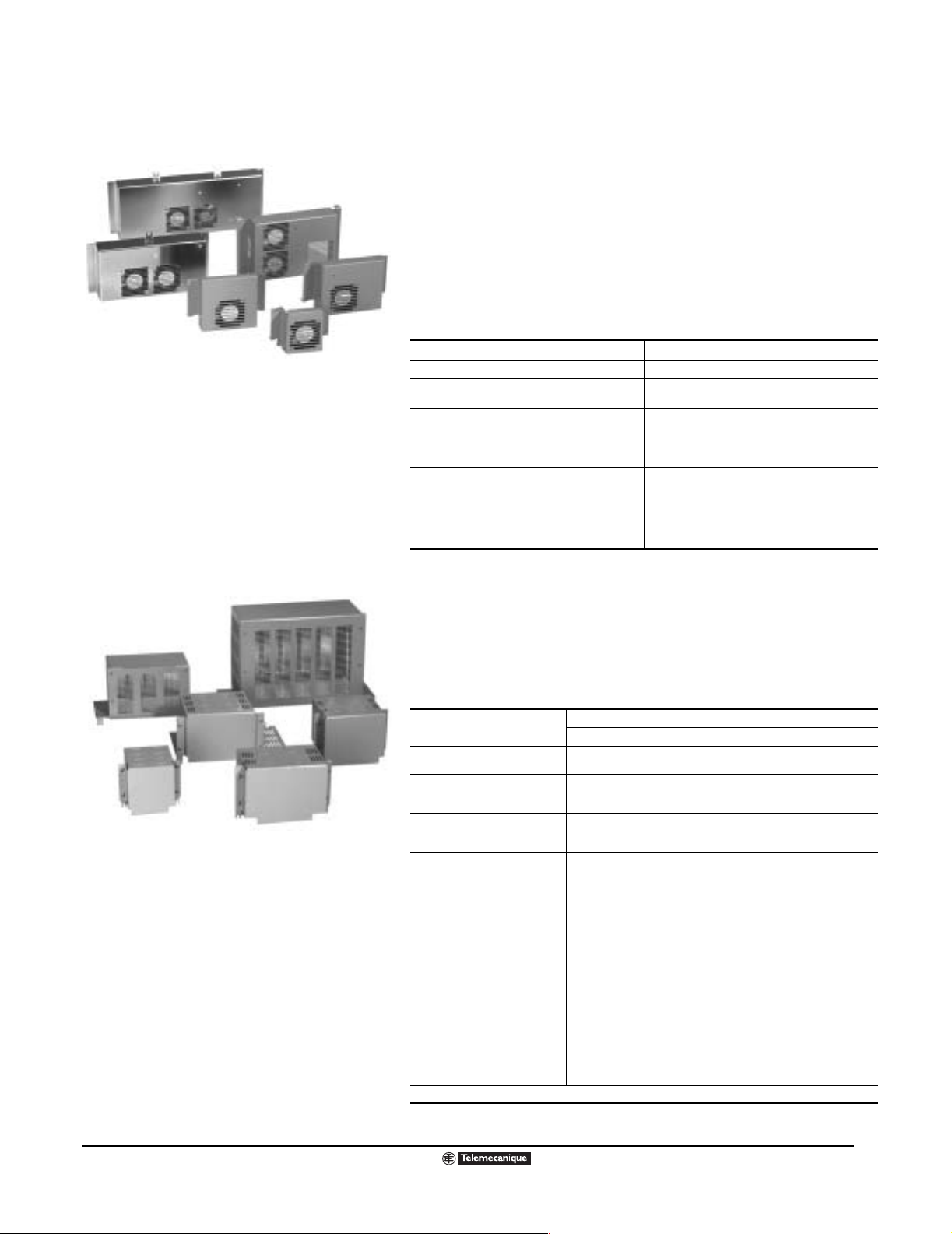
Ventilation Kits
Altivar
®
58 TRX AC Drives
Ventilation Kits and Conduit Entry Kits
VENTILATION KITS
Ventilation kits enable the ATV58 TRX controller to operate at a higher
ambient temperature as, for example, when mounted in an enclosure. The
VentKits.tif
circulation of air around the electronic cards prevents the formation of hot
spots. The f an ki t attaches to the upper p art of the controller, and is po wered
by the drive controller.
A ventilation kit contains the fan assembly, all necessary mounting
accessories, and a power cab le connector t hat plugs into th e power board on
the drive controller.
See page 115 for temperature ratings and page 125 for dimensions.
Ventilation Kit for Catalog Number
ATV58•U09M2, ATV58•U18M2 VW3A58821
ATV58•U29M2, ATV58•U41M2, ATV58•U18N4,
ATV58•U41N4
ATV58•U54M2, ATV58•U72M2,
ATV58•U54N4, ATV58•U72N4, ATV58•U90N4
ATV58•U90M2, ATV58•D12M2,
ATV58•D12N4, ATV58•D16N4, ATV58•D23N4
ATV58HD16M2X, ATV58HD23M2X,
ATV58HD28N4, ATV58HD33N4, ATV58HD46N4,
ATV58HD28N4X, ATV58HD33N4X, ATV58HD46N4X
ATV58HD28M2X, ATV58HD33M2X, ATVHD46M2X,
ATV58HD54N4, ATV58HD64N4, ATV58HD79N4,
ATV58HD54N4X, ATV58HD64N4X, ATV58HD79N4X
VW3A58822
VW3A58823
VW3A58824
VW3A58825
VW3A58826
Conduit Entry Kits
CONDUIT ENTRY KITS
Conduit Entry Kits are for use on wall-mounted drive controllers. A conduit
entry kit attaches to the bo ttom o f th e d riv e a nd provides multiple k nockouts
CondEntKits.tif
to land conduit for po wer and contr ol wire. The av ailabl e kits are shown in the
table below. See page 115 for enclosure ratings and pages 123–124 for
dimensions.
Catalog Number
VW3A58842
VW3A58843
VW3A58844
VW3A58845
VW3A58846
VW3A58847
VW3A58848
VW3A58849
VW3A58850
1 Availability to be announced.
1
1
1
For Drive Controllers
230 Vac 460 Vac
ATV58HU09M2
ATV58HU18M2
ATV58HU29M2
ATV58HU41M2
ATV58HU54M2
ATV58HU72M2
ATV58HU90M2
ATV58HD12M2
ATV58HD16M2
ATV58HD23M2
ATV58HD28M2
ATV58HD33M2
ATV58HD46M2
—
ATV58HU18N4
ATV58HU29N4
ATV58HU41N4
ATV58U54N4
ATV58U72N4
ATV58U90N4
ATV58HD12N4
ATV58HD16N4
ATV58HD23N4
ATV58HD28N4
ATV58HD23N4
ATV58HD46N4
ATV58HD54N4
ATV58HD64N4
ATV58HD79N4
ATV58HC10N4X
ATV58HC13N4X
ATV58HC15N4X
ATV58HC19N4X
ATV58HC23N4X
ATV58HC25N4X
ATV58HC28N4X
ATV58HC31N4X
ATV58HC33N4X
09/2003
© 2000–2003 Schneider Electric All Rights Reserved
33
Page 34

Altivar
®
58 TRX AC Drives
Dynamic Braking Resistor Kits
DYNAMIC BRAKING RESISTOR KITS
The dynamic braki ng res is tor k it al lo w s th e ATV58 TRX drive controllers to func tion in qua dran ts 2 and
4 of the four quadrant speed/torque curve. In these quadrants of motor operation, the motor is
essentially a generator through which energy is transferred from the motor load back to the drive
controller . This res ults in ele v ated DC b us v oltage to t he driv e controller which ma y cause it to shutdo wn
to protect itself. Dynamic braking resistor kits are commonly used to dissipate the excess energy
generated by the motor operating in this mode. The flow of current to the braking resistor is controlled
by the dynamic braking transistor (see the block diagrams on page 92–94).
The following table shows the minimum ohmic value of the resistor that can be used with the
ATV58 TRX drive contro llers . Usi ng lo w er than recom mended values will c ause excessive current flo w,
exceeding the rating of the dynamic braking transistor.
Minimum Ohmic Value of Resistor s
Which Can Be Used with ATV58 TRX Controllers
Model (ATV58) Minimum Resistance Value in Ohms Model (ATV58) Minimum Resistance Value in Ohms
U09M2
U18M2
U29M2
U41M2
U54M2 31 U90N4 47
U72M2 25 D12N4 53
U72M2
D12M2
D16M2X 8 D28N4, D28N4X
D23M2X 8
D28M2X 4 D54N4, D54N4X 8
D33M2X 2.67
D46M2X 2.67
U18N4
75
38 U72N4 57
13
U29N4
U41N4
U54N4
D16N4
D23N4
D33N4, D33N4X
D46N4, D46N4X
D64N4, D64N4X
D79N4, D79N4X
85
19
14
5
The following charts show the motor braking torque capacity of an ATV58 TRX drive controller with a
braking resistor.
Characteristics of Braking Module and Resistors
Braking Torque with Resistor
Constant-Torqu e Applications Varia ble-Torque Applications
%Torque
1
0
0.25
0.50
0.75
1.00
1.25
1.50
1. Continuous braking torque (driving load) load factor = 100%.
2. Maximum transient braking torque (for 60 s).
34
© 2000–2003 Schneider Electric All Rights Reserved
25/30 50/60 75/90 100/120
1
2
Speed (Hz)
%Torque
0.25
HiTorqGraf.eps
0.50
0.75
1.00
1.20
1.25
1.50
1. Continuous braking torque (driving load) load factor = 100%.
2. Maximum transient braking torque (for 60 s).
25/30 50/60 75/90 100/1200Speed (Hz)
1
1
2
LoTorqGraf.eps
09/2003
Page 35

Altivar
®
58 TRX AC Drives
Dynamic Braking Resistor Kits
Calculating Resistor Size
The standard dynamic bra k ing (DB) resistor assemblies are suitable for a wide variety of drive system
stopping applications. However, when the driven machinery may present an overhauling load or large
inertia to the drive system, the suitability of the DB resistor assembly should be checked.
The suitability of a DB resistor assemb ly is determined by analyzing the mech anical system of the driv en
machinery. From the analysis, the following key parameters are computed:
• The peak braking pow er requir ed during stop ping or speed ch anges (Pi). The value of Pi determines
the maximum allowable ohmic value of the DB resistor.
• The amount of power that must be absorbed (P
stopping or speed changes of the drive. The value of P
characteristic of the DB resistor.
• The calculation of dynamic braking power requires V
= 850 V for 460 V drives
•V
db
= 375 V for 230 V drives
V
db
• The aver age po w er that m ust be dissi pated b y the DB resi stor during an entire cy cle of th e mach ine
(P
). The value of Pa determines the required continuous current rating of the DB resistor.
a
The following example illustrates the process:
Given
The application consists of a 5 hp, 460 Vac, 1740 rpm motor (N
inertia of 0.28 lb-ft
2
. The motor is being co ntrolled b y an ATV58HU72N4 operating in t he consta nt
torque mode. The motor is driving a machine with an inertia 10 times that of the motor with no
interposing gear box . The machi ne resistiv e (friction) torq ue is one-ten th of the r ated motor t orque
at full speed. The requ irement is to stop in 5 seconds from r ated speed at a rate of 2 cycles/min ute.
) for a given time (td) by the DB resistors during
d
and td determine the required time-current
d
.
db
= base speed) with a rotor
base
Mechanical System Parameters:
Rated motor torque: T
Machine cycle time: t
= (hp x 5250)/N
n
= (60 seconds)/(two operations per minute) = 30 seconds
c
Machine speed change during deceleration: N
= (5 x 5250)/1740 = 15.1 lb-ft
base
= 1740 rpm - 0 rpm = 1740 rpm
d
Machine deceleration time: td = 5 seconds
Mechanical system resistive (friction) torque: T
Mechanical system overhauling torque: T
Mechanical system combined inertia: J
c
= (15.1 lb-ft)/10 = 1.51 lb-ft
r
= 0.00 lb-ft
o
= 0.28 lb-ft2 + (10) x 0.28 lb-ft2 = 3.08 lb-ft
2
Mechanical system inertial torque for a 5 second deceleration rate (as set by controller
deceleration ramp):
= Jc x (Nd)/(308 x (td)) = 3.08 x 1740/(308 x 5) = 3.48 lb-ft
T
j
Required braking torque from motor: T
= Tj + To - Tr = 3.48 + 0.00 - 1.51 = 1.97 lb-ft
b
NOTE: The required braking torque must not exceed the motor’s ability to produce torque. For
inertial loads, including those depicted in the above examples, the required braking torque must
not exce ed the torque pr oducing abilit y of the dynami c braking un it with the reco mmended br aking
resistor (approximately 1.5 times the motor rated torque for constant torque applications).
For machines that can contin uously ov erhaul the mot or, th e value of o verhau ling torque (To) minus
the resistive torque (T
) must not exceed the motor continuous torque rating at any speed.
r
09/2003
© 2000–2003 Schneider Electric All Rights Reserved
35
Page 36

Altivar
®
58 TRX AC Drives
Dynamic Braking Resistor Kits
DB resistor requirements:
Peak br aking pow er required to d ev elop braking torque (T
= Tb x N
P
i
The braking power that must be absorbed for a time (td) during stopping or speed changing
operation: P
The average braking power that must be dissipated during a machine cycle:
P
= Pd x td/tc = 243 x 5/30 = 40.5 W
a
Capability of VW3A66711 DB resistor assembly for ATV58U72N4 controller:
Peak bra king powe r that can be dev elope d with VW3A66711 DB resi stor assemb ly with controll er
configured for 460 Vac input line operation: P
The braking power that can be absorbed for t
characteristic curve shown on page 37):
= Rdb x ((Multiple of Ir at td) x Ir)2 = 120Ω x (3.5 x 1.0)2 = 1470 W
P
d
Since R
[(Multiple of I
The average braking power that can be dissipated continuously:
= Rdb x (Ir)2 = 120 Ω x (1)2 = 120 W
P
a
For this example, the VW3A66711 DB resistor assembly will work as intended for the application.
) when decelerati ng from a giv en speed
/(7.04) = (1.97 x 1740)/(7.04) = 487 W
base
= 0.5 x Pi = 0.5 x 487 = 243 W for a period of td seconds
d
= (Vdb)2/Rdb = (850 V)2/120 Ω = 6020 W
i
(based on DB resistor hot state current-time
d
limits the peak current tha t can be d ra wn fro m the driv e co ntroll er DC b us , the v al ue of
db
) x Ir] must be limited to no greater than (√ pi/Rdb).
r
b
36
© 2000–2003 Schneider Electric All Rights Reserved
09/2003
Page 37
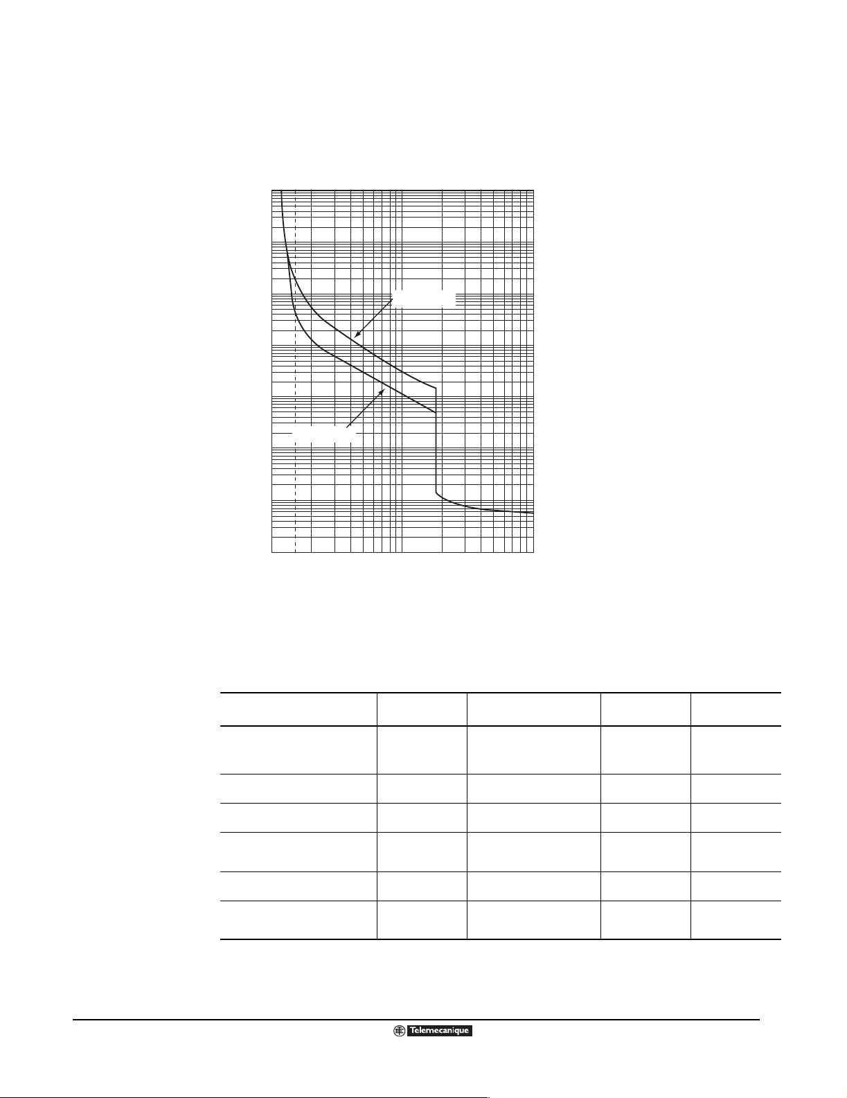
Altivar
®
58 TRX AC Drives
Dynamic Braking Resistor Kits
Current/Time Characteristics for DB Resistor Assemblies
The figure below shows the allowable GV2 trip times as a function of current setting multiples with the
dynamic braking res ist or as se mbly located in a 40 °C (1 04 °F ) am bie nt te mp erature environm ent. See
page 35 for an example of how to calculate resistor size.
10000
DynBrkCurves.eps
1000
100
Cold State
10
Time (s)
1
Hot State
0.1
0.01
0.001
1
1.5
10
100
Multiples of current setting (lr)
The kits in the following table use the thermal protection of a GV2 manual starter and have a Type 1
rating per UL 50. The ins ulati on system is sui tab le f o r use in a Pollution Degree 3 en viron ment (refer to
NEMA ICS-1 Annex A). The package is UL/CSA marked.
DB Kits Technical Specifications
09/2003
Dynamic Braking Kit for:
ATV58•U09M2▼, ATV58•U18M2▼,
ATV58•U18N4, ATV58•U29N4,
ATV58•U41N4, ATV58•U54N4,
ATV58•U72N4
AT V5 8•U2 9M2, ATV5 8•U41 M2,
ATV58•U90N4, ATV58•D12N4
AT V5 8•U5 4M2, ATV5 8•U72 M2,
ATV58•D16N4, ATV58•D23N4
AT V5 8•U9 0M2, ATV5 8•D12 M2,
ATV58•D28N4, ATV58•D33N4,
ATV58•D46N4
AT V5 8•D1 6M2, ATV5 8•D23 M2,
ATV58•D54N4
AT V5 8•D2 8M2, ATV5 8•D33 M2,
AT V5 8•D4 6M2, ATV5 8•D64 N4,
ATV58•D79N4
◆ Current rating of resistor assembly is calculated based on setting of internal overload protective device in assembly, overload setting based on
enclosure overtemperature prote ction, and resistor overload versus time characteristics. Resistor s are r ated for stopping six times rotor inertia of fourpole motor with drive at current limit. Motor inertias are based on NEMA MG-1 14.45.
▼
Requires external braking transistor, VW3A58701.
Ohmic Value
(Rdb)
120 Ω 1.0 A 120 VW3A66711
56 Ω 1.45 A 118 VW3A66712
28 Ω 2.7 A 204 VW3A66713
14 Ω 3.8 A 202 VW3A66714
10 Ω 10.0 A 1000 VW3A66715
5 Ω 14.0 A 980 VW3A66716
Continuous Current Rating
of Assembly
◆
(Ir)
Average Power
(W)
Catalog Number
© 2000–2003 Schneider Electric All Rights Reserved
37
Page 38

Altivar
®
58 TRX AC Drives
EMC Kits and RFI Filters
ELECTROMAGNETIC COMPATIBILITY (EMC) KITS
ATV58 TRX drive controllers are marked with the CE European Community mark.
The ATV58 TRX driv e controll er is considere d to be a componen t. It is neither a machi ne nor a piece of
equipment ready for use in accordance with the European Community directives (machinery directive
or electromagnetic compatibility directive). It is the user’s responsibility to ensure that the machine
meets these standards.
Metal EMC plate kits are available for ATV58 TRX drive controllers to assist in meeting the European
Community EMC directi ves. Th e plate is used f or landing the shield of the shielded cab le. These ki ts are
for integra tors and end-us ers who are incl uding the driv e cont roller as part of a machine to be e xported
to Europe requiring compliance to these directives. When installed as directed in Instruction Bulletin
30072-450-04 (shipp ed with the k it), the requi rement s of EM C Di rective Lev el A will b e me t. To achieve
Level B comp liance , i nstall an external RFI filter (see the following sec tions ). See pag e 125 for EMC kit
dimensions.
EMC Kit Catalog Numbers
For Drive Controllers
ATV58•U09M2, ATV58•U18M2 VW3A58831
ATV58•U29M2, ATV58•U41M2, ATV58•U18N4, ATV58•U29N4, ATV58•U41N4 VW3A58832
ATV58U54M2, ATV58U72M2, ATV58U54N4, ATV58U72N4, ATV58U90N4 VW3A58833
ATV58U90M2, ATV58D12M2, ATV58D12N4, ATV58D16N4, ATV58D23N4 VW3A58834
EMC Kit Catalog
Number
INTERNAL RFI FILTERS
The ATV58 TRX drive controller can be supplied wit h internal radio interf erence supp ression input filters
to comply with the EMC “produ cts” st andards IEC 618 00-3 and EN 6180 0-3 conce rning variab le speed
controllers. Compliance with these standards meets the requirements of the European directive on
EMC.
The follo wing ATV58 TRX controllers are available without input filters for use in situations where EMC
conformity is not necessary:
• ATV58HU54N4 to ATV58HD79N4 drive controllers are available with or without integrated input
filters. If the catalog number includes an “X”, the drive controller does not have an integrated input
filter.
• ATV58HD16M2X to ATV58HD46M2X drive controllers are not available with integrated input filters.
The following ATV58 TRX drive controllers are always supplied with integrated input filters:
•ATV58•U09M2 to ATV58•D12M2 drive controlle r s; and
•ATV58•U18N4 to ATV58•U41N4 drive controllers .
EXTERNAL RFI FILTERS
External RFI input filters are available to meet the strictest requirements. These filters are designed to
reduce conducted emis sions on the m ains s upply to belo w th e limi ts of sta ndards EN 55022 c lass B or
EN 55011 class A. The motor cable must be longer than 5 m (16 feet) for ATV58•U09M2 to
ATV58•D12M2 and ATV58•U18N4 to A TV58• D23N4 control lers, or 25 m (82 f eet) f or ATV58HD28N4 to
ATV58HD79N4 co ntro lle rs .
External RFI filters are mounted beneath ATV58 TRX Type H controllers. They have tapped holes for
mounting the drive controller which the y support. The filters are mounted to the side of A T V58 TRX Type
E controllers.
Because the filter need s a direct path to gr ound to work pro perly, RFI fil ters can onl y be us ed on
wiring systems with a neutral connected directly to ground. Do not use RFI filters on wiring
systems grounded through a high impedance or on systems with an isolated (floating) neutral.
38
© 2000–2003 Schneider Electric All Rights Reserved
09/2003
Page 39

Altivar
®
58 TRX AC Drives
Line Reactors and Output Filters
Wiring systems with a ne utr al connected directly to g rou nd c an be classified in two ways, as TT or TN.
1. TT indicates a neutral wire connected directly to ground. The exposed conductive parts of the
product are connected to grou nd via a separate path.
2. TN indicates a neutral wire connected directly to ground and the exposed conductive parts of the
product are connected to ground via the same path.
Wiring systems grounded through a high impedance or systems with an isolated (floating) neutral can
be referred to as IT. Standard IEC 1800-3, appendix D2.1, states that filters must not be used with IT
mains supplies because they prevent the ground leakage detectors from working reliably. In addition,
the effec tiv ene ss o f th e filt ers on IT m ains suppl ies d epend s on the type of im pedan ce be tw een ne utral
and earth, and is therefore not recomm en ded .
In the case of a machine which must be installed on an IT supply, the solution is to insert an isolation
transformer and operate the machine locally using a TN or TT supply.
Characteristics
Conformity to standards
Degree of protection
Maximum relative
humidity
Ambient air temperature
Operating altitude
Maximum nominal voltage
Operation –10 to 60 °C (14 to 140 °F)
Storage –25 to 70 °C (–13 to 158 °F)
Up to 1000 m (3280 feet) No derating required
Above 1000 m (3280 feet) Derate the current by 1% for each additional 100 m (328 feet)
50/60 Hz single-phase 240 Vac +10%
50/60 Hz 3-phase 500 Vac +10%
EN 133200
IP 21 and IP 41 on upper part
93% with no condensation or dripping water, conforming to IEC 68-2-3
Refer to page 125 for dimensions and to page 132 for selection.
LINE REACTORS
Line reactors can improve protection against line overvoltage surges and reduce input currents to the
drive controller by adding impedance. The additional impedance also reduces the harmonic current
distortion produced by a typical 6-pulse diode rectifier used to convert AC to DC in most drive
controllers. Additional impedance is recommended when the impedance of the power distribution
system is low, such as when the power rating of the system transformer is ten times larger than the
power rating of the driv e controll er . Singl e-phase li ne reactors are av ail able f or sin gle-phase input rat ed
ATV58 TRX Type H drive controllers. See pages 125, 132, and 133 for dimensions and selection.
MOTOR PROTECTING OUTPUT FILTERS
The motor protecti ng output fi lters com bine ind uctance , capac itance , and res istance to f orm a low pas s
filter . They should be considere d for use in applications w here the wiring to the mot or(s ) is lo nge r than
100 ft. (30.5 m). Th ese filte rs lo wer the dv /dt le v els to prevent e x citing th e natura l resonan t frequency o f
the output circuit (drive controller, motor cables, and motor). Motors compliant to NEMA MG1, Part 31
guidelines gener ally do not requ ire the u se of m otor prote cting fi lters. See page 133 f or di mension s and
selection.
09/2003
© 2000–2003 Schneider Electric All Rights Reserved
39
Page 40

Altivar
®
58 TRX AC Drives
Macro-Configuration Programming
MACRO-CONFIGURATION PROGRAMMING
ATV58 TRX drives have a macro-config ur ation menu that can be used to pre-progr am the drive for the
application to simplify configuration. Three options are available:
• Material handling (factory default setting)
• General use
• Variable torque
NOTE: 125–500 hp drive controllers have only the variable torque macro.
Selecting one of the macro-configurations will automatically assign the functions, parameters, and
I/O of the ATV58 TRX controller and option cards (if i nstall ed). Th ese c onfig urati ons c an be mod ified at
any time if necessary. If a confi guration is modi fied, the drive controll er will displa y “customize d” in place
of the name of the macro-configuration previously selected.
The pre-configured functions for each macro-configuration are shown in the table below.
Factory-Configured Functions for the Three Macro-Configurations
Basic I/O
Logic input LI1 Forward Forward Forward
Logic input LI2 Reverse Reverse Reverse
Logic input LI3 2 preset speeds Jog operation Auto-Manual
Logic input LI4 4 preset speeds Freewheel stop/Run permissive
Analog input AI1 Reference summing Reference summing Speed reference 1
Analog input AI2 Reference summing Reference summing Speed reference 2
Analog output AO1 Motor frequency Motor frequency Motor frequency
Relay R1 Drive fault relay Drive fault relay Drive fault relay
Relay R2 Output contactor control Motor thermal state attained Frequency reference attained
Analog or Digital I/O Extension Cards
Logic input LI5 8 preset speeds Fault reset Freewheel stop
Logic input LI6 Fault reset Current limit Ramp switching
Analog input AI3 (analog I/O card)
or
Encoder Inputs (digital I/O card)
Logic output LO Current threshold attained Output contactor control High speed attained
Analog output AO Motor current Motor current Motor current
[1] Factory default setting for 100 hp products and below.
[2] If the Freewheel Stop/Run Permissive function is configured, the drive controller will not start the motor unless the logic input is connected to +24 V.
[3] For 125–500 hp controllers, the factory settings are:
LI3 = fault reset; LI4 = Not assigned; AI1 = Reference summing; AI2 = Reference summing; R2 = Drive running.
Material Handling
Summing speed reference Summing speed reference PI regulator
Speed regulation Speed regulation Speed regulation
[1]
General Use Variable Torque
[3]
[2]
DC injection braking
[3]
[3]
[3]
[3]
DRIVE CONTROLLER IDENTIFICATION SCREEN:
INCREASING POWER RATING FOR VARIABLE TORQUE APPLICATIONS
This screen can always be displayed, and shows the power rating and volt age of th e drive controller. It
can also be used to increase the power rating for variable torqu e appl ic ati ons usi ng 20 8/2 30 Vac drive
controllers of at least 10 hp or 460 Vac drive controllers of 3 to 100 hp.
40
© 2000–2003 Schneider Electric All Rights Reserved
09/2003
Page 41

Altivar
®
58 TRX AC Drives
Display Parameters
DISPLAY PARAMETERS
The Display parameters, described in the following tables, can be viewed in any access level from the
Display Me nu. Use the arrow k eys on the ke ypad displa y or prog rammin g terminal to scroll through this
parameter set. The following parameters can be viewed under Drive State in the Display Menu. They
are used for monitoring drive controller operation.
Parameter STATUS Description
Drive State RDY Drive controller is ready to run.
RUN Drive controller and motor are running in a steady state.
ACC Drive controller is accelerating the motor.
DEC Drive controller is decelerating the motor.
CLI Drive controller is in current limit.
DCB Drive controller is injecting DC current for braking the motor.
NST Drive controller has been commanded to freewheel stop.
OBR Drive controller is decelerating the motor as fast as possible.
The following parameters can also be viewed from the Display Menu.
Parameter Units Description
Reference Frequency Hz
Output Frequency Hz Displays the output frequency being applied to the motor.
Motor Speed rpm Motor speed in RPM based on user specified motor RPM.
Motor Current A Current being drawn by the motor.
Machine S peed ---
Output Power %
Line Voltage Volts Displays the voltage measured at the input of the drive.
Motor Thermal %
Drive Thermal %
Last Fault
Watt-Hour Meter kWh or MWh Displays energy consumed in kWh or MWh when kWh reaches 9999
Run Time Meter hrs Operating time (motor powered) in hours
Displays the frequency the drive con troller is commande d to run. (If u sing the ke ypad to
control the drive, the speed reference can be entered at this screen.)
Value displayed based on user specified scaling factor multiplied by the output
frequency. The scaling factor has a range of 0.01 to 100.
Displays the percent of power the being drawn by the motor.
100% corresponds to nominal current rating of the drive.
Displays the thermal state of the motor.
100% corresponds to nominal motor thermal state.
Displays the thermal state of the drive controller.
100% corresponds to nominal drive controller thermal state.
The following faults can be displayed:
Input phase loss Undervoltage Overvoltage,
Drive overheating Motor overload Overb r aking
Motor phase loss Loss of 4-20mA signal Overcurrent
Motor short circuit Pre-charge fault Loss of RS-485
Motor overheating Thermal senor fault EEPROM fault
Internal fault External fault Overspeed
Speed feedback fault Ramp not followed Config. fault
Communication Network fault Internal comm fault Option removed
09/2003
© 2000–2003 Schneider Electric All Rights Reserved
41
Page 42

(Hz)
SP
0
0
y
.
SP
(Hz)
SP
0
0
y
.
SP
(Hz)
SP
0
0
y
.
SP
(Hz)
t1
t
50/60
0
p
ps
t
(Hz)
50/60
0
t1
p
ps
Altivar
®
58 TRX AC Drives
Adjustment Parameters
ADJUSTMENT PARAMETERS
High
Speed
Low
Speed
0 V
0 mA
x mA
20 mA
10 V
20 mA
y mA
4 mA
Low Speed and
High Speed Diagram
Adjustment parameters can be viewed and modified when the access locking switch on the keypad
display is not loc k ed (se e page 24). Adj ustme nt par amet ers can be mo dified with the motor sto pp ed or
running.
HiLoSpd.eps
Low Speed and High Speed
These frequency limits define the speed r ange permitted, as shown in the graph to the left. Low speed
is adjustable from 0 to t he High Sp eed set tin g and is f acto ry set at 0 Hz. Hig h Speed is adju st ab le from
Low Speed to 500 Hz and is factory set to 50 or 60 Hz, depending on the configuration. The speed
reference inp ut i s sc ale d between Low Spe ed a nd H igh Spe ed. It i s p os sible to modify the s c ali ng wi th
the Low Speed Operation parameter.
Low Speed Operation
The Low Speed Operation parameter determines the two limits, High Speed (HSP) and Low Speed
(LSP), that define the speed range permitted by the machine under actual operating conditions. This
function can be used for all applications. The following table describes the three settings that can be
assigned for this function.
Normal Mode Pedestal Mode Deadband Mode
H
OpSpd_Pdstl.eps
L
1
OpSpd_Nml.eps
H
L
Ref
1
H
L
Ref
1
OpSpd_Dbnd.eps
Ref
LSP (Low Speed): From 0 to HSP, preset at 0. HSP (High Speed): from LSP to FMAX, preset at 50/60 Hz
x: configured from 0 to 20 mA, preset at 4 mA y: configured from 4 to 20 mA, preset at 20 mA
Maximum Frequency
Maximum Frequency is used as a maximum speed clamp. The High Speed setting can not be above
the Maximum Frequency setting. Maximum Frequency is adjustable from 40 to 500 Hz and factory set
to 60 Hz or 72 Hz depending on the 50/60 Hz switch configuration.
Acceleration and Deceleration Ramp Times
The ramp times f or acc eleration and deceler ation are de termined by th e requiremen ts of the appl ication
and the dynamics of the mach ine . The f ollow ing tab le sho ws the accel erat ion and dece leration settings .
Acceleration Deceleration
.e
cc_Ram
Adjustment from 0.05 to 999.9 s, preset at 3 s. Adjustment from 0.05 to 999.9 s, preset at 3 s.
.e
ec_Ram
Electronic Inversion of Output Phase
This parameter can be used to change the direction of motor rotation. This parameter is useful if it is
determined, after the motor wiring has been connected, that the motor is not rotating in the correct
direction.
42
© 2000–2003 Schneider Electric All Rights Reserved
09/2003
Page 43

(Hz)
ce
5 Hz
p
q
p
Altivar
®
58 TRX AC Drives
Adjustment Parameters
Skip Frequency
s
.e
This parameter , al so ref erred to as jump freq uency, allows sup pression of a critic al speed whic h causes
Fre
ki
mechanical resona nc e p hen om ena . Prol ong ed ope ration of the motor withi n a frequency band of 5 Hz
is prohibited. Th e frequ ency band is adjus tab le over the s peed range . A repres entatio n o f this is sho w n
to the left. There are three skip frequency settings.
Skip Frequency
Diagram
Referen
This function is useful f or applica tions in v olving li ght-weig ht machine s, suc h as bu lk product conv e yo rs,
with unbalanced motors. It is also useful for applications involving fans and centrifugal pumps.
Low Speed Run Time Limit
This function, also referred to as a sleep function, is used to stop the motor after running at low speed
for a progr ammed amoun t of time, w ith the run command present and z ero speed ref erence . The length
of run time at low speed is adjustable from 0.1 to 999.9 seconds. The factory setting is 0 s, which
disables this function. The motor will re-start if the frequency reference becomes greater than the low
speed or the run command is cycled.
This function can be used for automatic starting and stopping of pressure-regulated pumps.
IR Compensation
This parameter is used to adjust low-speed torque for optimal performance. Adjust this parameter to
compensate for the resistive voltage drop of the motor stator windings and the conductors connecting
the motor and drive controller.
The factory setting is 100%, with a range of 0 to 150%. (If using special motors such as synchronous
permanent magnet motors, synchronous wound field motors, or synchronous reluctance motors, the
adjustment range can be expanded and is 0 to 800%.)
This parameter is typically used to boost torque performance during low speed operation. If an autotune is performed, adjustment of this parameter is usually not required.
Slip Compensation
This paramete r is us ed to adjus t the slip c ompe nsati on to i mpro v e s peed regulat ion.The factory setting
is 100%, with a range of 0 to 150%.
Induction motors develop torque based on the slip, which is the difference between the speed of the
rotating magnetic field in th e stato r and t he speed of the rotor. As the lo ad inc reases , the sl ip inc rea ses
to produce the n ec es sa ry torque . In applications where the change in s pee d due to s lip i s u ndesirable ,
the slip compensation should be increased. When this parameter is increased, the drive controller will
automatically increase the output frequency. The amount of increase is proportional to the increase of
the load, allowing one setting for the entire speed range.
Gain
This parameter al lows adjustmen t of the drive controll er’s res ponse time to sudden ch anges in the motor
load. The factory setting is 20%, with a range of 0 to 100%.
Decreasing the gain parameter slows the response time of the drive. Increasing the gain parameter
makes the drive respond more quickly. This par am ete r s hou ld b e increased when it is no t de si ra ble for
motor speed to chang e as the moto r load chan ges, su ch as in app licat ions that ha v e f ast cyc le times or
high torqu e requirements.
Stability
This parameter allows adjustment of speed overshoot of the drive controller to sudden changes in the
motor load. The factory setting is 20%, with a range of 0 to 100%.
Increasing the s tability se tting dampen s the ov ershoo t. This par ameter shoul d be adjuste d with the gain
setting to tune t he drive respons e to meet desired performance on applications that have f ast cycle tim es
or high torque requirements.
09/2003
© 2000–2003 Schneider Electric All Rights Reserved
43
Page 44

Altivar
®
58 TRX AC Drives
Drive and Motor Configuration Parameters
DC Current Injection
This parameter allows the driv e t o i nje ct D C cu rrent into the stator, creating a s t ati ona ry magnet ic po le
which brakes the rotor at the end of each stop command when the frequency drops below 0.1 Hz.
This feature is useful when a coasting motor is undesirable at the end of the deceleration ramp. The
factory setting is for this f eature is “en ab led”. T he t ime o f DC cu rrent in jecti on is adjus tab le fro m 0 to 30
seconds, with a factory setting of 0.5 seconds. A continuous setting is also available. If the continuous
setting is selected, the drive controller brakes at the nominal current rating of the drive for 30 seconds,
and then continuously at 50% of rated current. The level of current is adjustable from 10% to 136% of
the drive controller’s constant torque current rating.
DRIVE AND MOTOR CONFIGURATION PARAMETERS
Drive and motor configuration parameters can be viewed and modified only when the access locking
switch on the keypad display is in the total unlock position (see page 24). These parameters can be
modified only when the motor is stopped.
Input Frequency
The controller is e quipped with a tw o-position s witch, whi ch is used to se lect 50 or 6 0 Hz input frequen cy .
Nominal Motor Voltage
This parameter is used to enter the nominal motor voltage given on the motor nameplate.
The factory setting is 230 Vac with a range of 200 to 240 Vac for the ATV58•M2 models. For the
ATV58•N4 models, when the input frequency switch is set to 60 Hz, the factory setting is 460 Vac with
a range of 200 to 500 Vac; when the switch is set to 50 Hz, the nominal motor voltage defaults to
400 Vac with a range of 200 to 500 Vac.
Nominal Motor Frequency
This parameter is used to enter the nominal motor frequen cy given on the moto r nameplate. The f actory
setting is 60 Hz when the input frequency switch is set to 60 Hz. When the switch is set to 50 Hz, the
nominal motor frequency defaults to 50 Hz. The range is 10 to 500 Hz. The nominal motor frequency
setting defines the frequency at which nominal motor voltage is applied to the motor. The parameter
cannot be set above the maximum output frequency setting.
Vac
Voltage profile =
460
60 Hz
Voltage profile =
120 Hz
60 120
Nom-Mot-Freq (catalog).eps
Hz
Nominal Motor Current
This parameter is used to enter the nominal motor current given on the motor nameplate. The factory
setting is 90% of the drive controller’s constant torque current rating. The range for this parameter is
25% to 136% of the constant torque current rating.
Nominal Motor Speed (rpm)
This parameter is used to enter the nominal motor speed (rpm) given on the motor nameplate. The
factory setting depends on the drive controller setting. The range for this parameter is 0 to 9999. This
value should correspond to the full load RPM (that is, this value should incorporate slip).
44
© 2000–2003 Schneider Electric All Rights Reserved
09/2003
Page 45

Altivar
®
58 TRX AC Drives
Drive and Motor Configuration Parameters
Motor Power Factor
This parameter is used to enter the motor power factor given on the motor nameplate. This allows the
drive to provide better current regulation for better motor torque performance. The factory setting
depends on the drive controller rating. The range for this parameter is 0.5 to 1.
Auto Tune
This parameter causes the drive controller to auto tune the connected motor. When Auto Tune is
initiated, the driv e controlle r allows a pu lse of current t o pass to the con nected motor , and m easures and
stores motor st ator resistance and con du cto r re sis ta nce. This allo ws the drive to prov ide be tter current
regulation f or improv ed motor torque perf ormance. A uto T une c an be initiated from the k eypad, b y a logic
input assigned to this function, or over a serial communication link.
Automatic Adaptation of the Deceleration Ramp
This function p rovide s autom atic adap tation of the dece leration ramp i f the progra mmed r amp sett ing is
too low f o r the inertia of the l oa d. This p revents po ssib le f a ulting of th e drive controller du e to e x cess iv e
braking. All appli cations, e xcept those requiring precise stoppin g and those which use braking resisto rs,
may benefit from this function.
The setting of this function is either Yes or No, with the default setting determined by the macroconfiguration. A utomati c adaptati on must be cance lled if the machi ne has position control with stopp ing
on a ramp and a braking resistor installed. If a braking sequence is configured, this function is
automatically dis abled.
Alternate Ramp Switching using Frequency Threshold
Alternate ramp switching allows switching between two sets of acceleration and deceleration ramp
times, with each set being adjusted separately. To switch between the two sets, a frequency threshold
can be defined. (A logic input may also be configured for ramp switching; see page 53.)
Ramp switching is particularly suited for the following:
• Material handling applications that require smooth starting and approach.
• Applications involving fast, steady-state speed correction.
• High-speed lathes with limitation of acceleration and deceleration above certain speeds.
09/2003
© 2000–2003 Schneider Electric All Rights Reserved
45
Page 46

SPHSP
t1
0
0
(Hz)
(Hz)
t2
t2
t
t
(Hz)
(Hz)
SP
P
0
0
t2
t2
t1
t1
t
p
p
t
Altivar
®
58 TRX AC Drives
Drive and Motor Configuration Parameters
Acceleration and Deceleration Ramp Profile
The ramp profile f or a cceleratio n and de celera tion is the g radua l change o f the output fre quency fro m a
speed referenc e f ollowin g a linear or pr edetermined r atio that en able s the r amps to be giv en an S- or Ushaped profile. For th e ATV5 8 TRX controller , the s election of a ramp pro file (line ar , S, o r U) aff ects both
the acceleration and deceleration ramps.
An S-shaped ramp profile ta kes up mechan ical pla y, eliminates jolts, and li mits “non -f ollo wing” of s peed
during rapid transient operation of high-inertia machines. They are particularly suited to applications
involving materials handling, packaging, and personnel transportation.
U-shaped ramp profi les are ideal f or pumping applic ations (installatio ns with centrifugal pum ps and nonreturn valves) because they improve control over valve operation.
The table below provides graphical representations of these two ramp profiles.
S-Shaped Ramp Profile U-Shaped Ramp Profile
H
S_Ramp.eps
s
H
HS
.e
_Ram
The curve coefficient is fixed, with t2 = t1 x 0.6 (t1 is the set ramp time). The curve coefficient is fixed, with t2 = t1 x 0.5 (t1 is the set ramp time)
Torque Limit
A torque limit can be implemented in three ways on constant torque rated products:
• With the Torque Limit parameter. This parameter is factory set at 200% and can be adjusted from 0
to 200% of the drive controller’s constant torque rating.
• With a logic input and an associated torque limit (see Torque Limit by Logic Input).
• With an Analog Input (see Torque Limit by Analog Input).
Current Limit
This parameter can be u sed to limit th e maxim um motor cur rent. Thi s param eter is f actory set at 13 6%,
and can be adjusted from 25% to 136% of the drive controller’s constant-torque output current rating.
Switching Frequency
This function allo ws configura tion of the drive output transi stors’ switc hing frequencies . Refer to the drive
controller rating tab le for contin uous current ratings and ass ociated switchin g frequency . The table bel ow
shows the available switching frequencies by type (parameter SFt) for each ATV58 TRX model.
Configurable Switching Frequenc ies
ATV58 TRX Models LF Type (kHz) HF1, HF2 Type (kHz)
ATV58•U09M2 to ATV58•D12M2
ATV58•U18N4 to ATV58•D23N4
ATV58HD16M2X and ATV58HD23M2X
ATV58HD28N4 to ATV58HD46N4
ATV58HD28M2X to ATV58HD46M2X
ATV58HD54N4 to ATV58HD79N4
ATV58HC10N4X to ATV58HC33N4X 0.5, 1, 2 4
0.5, 1, 2, 4 8, 12, 16
0.5, 1, 2, 4 8, 12
0.5, 1, 2, 4 8
ATV58 TRX drive con trollers hav e an autom atic fea ture that is used if the drive co ntroller is intermittent ly
used at the high end of i ts temperat ure rating and HF1 or HF2 s witchin g frequency ty pe is prog rammed.
In this configur ation, if th e drive controller thermal state goe s abov e 95%, the s witching frequency d rops
into the LF: Low Freq. type range of 2 or 4 kHz depending on the drive controller rating (see the table
above). When the thermal state cools to 70%, the switching frequency returns to the set value.
46
© 2000–2003 Schneider Electric All Rights Reserved
09/2003
Page 47

0
0.5
limit
C
r
r
00%CLI
50%CLI
SP
n
p
Altivar
®
58 TRX AC Drives
Drive and Motor Configuration Parameters
A higher s witching frequency will produce a wavef orm with less harmo nic distortion and allo w the current
regulator in the drive controller to perform better. Cable lengths greater than 330 feet (100 m) may
require adjusting th e switching frequenc y to lower setting s to redu ce the transmission line ph eno me na
that tends to develop in long conductors.
Motor Noise Reduction
When this parameter is enabled, the switching frequency is randomly modulated to avoid audible
resonance from the motor. This parameter is useful in applications where audible motor noise is
undesirable.
Energy Economizer
This function is en abled when the V ariable Torque macro-configuration is selected. When this parameter
is enabled, t he d riv e co ntrol ler optimizes the moto r efficiency by autom ati cal ly adj us tin g the volts/hertz
ratio. The drive controller accelerates the load with a constant volts/hertz ratio. When the reference
speed is attained, th e drive controll er begins low ering the voltage applied until the cu rrent begins to rise.
It operates at th is point until the speed ref ere nce is c hanged. T his par ameter is us eful f or sa ving energ y
in all variable torque applications.
Volts/Hertz Adjustment
This function is a vailabl e in variable torque mode and if the Energ y Economizer functio n is disabled. This
parameter is useful in applications where the user wishes to define the volts/hertz profile manually
instead of having the drive controller perform this function with the Energy Economizer function.
The factory default is set to 20%, with an adjustment range of 0 to 100%.
1
oldai
Hotai
Current Limit
Adaptation Curves
Current Limit Adaptation
s
anLoad.e
This function is available in variable torque mode, and provides for the automatic adaptation of the
current limit according to the speed to avoid a motor overload fault. It is used in applications involving
fans where the load curve of the fan changes with the air density, as shown in the graph to the left.
f/f
H
Special Motor Adaptation
This parameter should be en abled w hen using special mo tors such as s ynchronous permanent magnet
motors, synchronous wound field motors, or synchronous reluctance motors. This parameter should
also be enab led when one driv e is used to cont rol multiple mo tors in parallel. See the Thermal Protection
of Motor belo w for more i nformation. Enab ling this par ameter increases the IR compensat ion adjustment
range from 0 to 8 00%. This param eter ca n also be used in testing whe n a v ery small mo tor is us ed only
to verify proper operation of a drive system wiring and control.
09/2003
© 2000–2003 Schneider Electric All Rights Reserved
47
Page 48

0.7
t
6
5
242036
30
60
50
0.8
0.9 1.0 1.1 1.2 1.3
1.5
e
cold state
0
min
0
s
n
Altivar
®
58 TRX AC Drives
Drive and Motor Configuration Parameters
Thermal Protection of Motor
This function provid es indirect the rmal protection o f the motor b y cont inuous
calculation of its theoretical temp erature rise. The drive controller will fault if
the calculated temperature rise exceeds 118% of the nominal temperature
rise.
For applications using self-cooled or force-cooled motors, the
microprocessor calc ulates the theoretic al temperatur e rise of the motor usi ng
the following elem ents :
• Operating frequency.
• Current drawn b y the mo tor.
• Operating time.
• Maximum ambient temperature of 40 °C (104 °F) around the motor.
The following adjustments may be made:
• 0.25 to 1.36 times the nominal current of the drive controller’s constant-
• Adjust to the nominal current indicated on the motor rating plate.
NOTE: When the drive controller de-energizes, the I
and the cooling effect is calculated.
This function may also be used for specialized applications. Thermal
protection may be customized in the fault configuration menu for:
1
2mi
1mi
1
Thermal Protection Tripping Curves
ThermProt.eps
hot stat
I/I
torque rating, preset at 0.9.
2
t calculation is saved
• Applications with force-cooled motors. See the tripping curves at left for
the nominal frequency 50/60 Hz.
• Inhibiting thermal protection in harsh environments where temperatures
exceed 40 °C (104 °F) around the motor or where there is a risk of the
cooling fins becoming clogged. In these applications, provide direct
thermal protection using PTC thermistor probes built into the motor.
• Protection of motor u sing PTC probes . See “Thermal Protecti on with PTC
Probes” below.
• In the case of motors connected in parallel on the same controller, each
motor starter must be fitted with a thermal overload relay.
Thermal Protection with PTC Probes
This function provi des th ermal protec tion of the mo tor. The functio n must be
assigned to analog input AI3 on the I/O Extension Card with Analog Inputs
and the motor must be equipped with PTC probes.
The maximum resistance of the probe circuit at 20 °C (68 °F) is 750 Ω (3 x
250 Ω probes in series). The probe break and probe short-circuit faults are
monitored.
Thermal Protection of ATV58 TRX Controller
This function pro vides direct thermal protectio n via a thermistor affix ed to the
heatsink, thus ensuring component protection even in the case of faulty
ventilation or excessive ambient temperature. When an overtemperature
condition is sensed, the controller will fault on drive overtemperature.
48
© 2000–2003 Schneider Electric All Rights Reserved
09/2003
Page 49

ATV58 Control Terminals
x
s
p
d
se
0
0
0
0
Motor Frequency
Altivar
®
58 TRX AC Drives
Drive Control Parameters
DRIVE CONTROL PARAMETERS
Drive control par am eters ca n be vie w ed a nd modifie d on ly when the acces s
locking s wi tch on the k e ypa d displ a y is in the t otal unloc k posit ion (se e page
2-wire.eps
24). They can be modified only when the motor is stopped.
Two-W ire Control
LI1 = Forward LIx = Reverse
Two Wire Con trol
ATV58 control terminal
LI1 = Stop LI2 = Forward LIx = Reverse
Three Wire Control
Sto
Forwar
Rever
Three Wire Control Timing
Diagram
The drive controller is factory-configured for two-wire control. The two-wire
control function controls operation direction using maintained contacts.
Depending on whethe r one or two directio ns of operation are required b y the
application, one or two logic inputs must be assigned to this function. An
example of wiring for two-wire control is shown to the left. Three operating
LI
3-wire.eps
modes are possible:
• Detection of the state of logic inputs.
• Detection of a change in the state of logic inputs.
• Detection of the state of logic inputs with Forward operation ha ving priority
over Reverse operation.
Three-Wire Control
The three-wire control function controls operation and stopping direction
using momentary contacts. Depending on whether one or two directions of
operation are required by the application, two or three logic inputs must be
PlusMinusSpd.eps
assigned to this function. An example of wiring for three-wire control is shown
to the left. Three-wire control is appropriate for all types of applications with
one or two operating directio ns.
Reverse Inhibit
This function disables reverse operation. It disables the REV key on the
keypad display and also prohibits reverse operation commanded by the PI
Regulator or Speed Reference Summation functions. Applications such as
those involving pumps, fans, or other applications where reverse operation
may cause mechanical damage may require reverse to be disabled.
Frequency
HSP
LSP
0
XY20
Analog Input 2 Scaling
09/2003
AI 2
(mA)
Analog Input Configuration
This parameter allows Analog Input 2 (AI2) on the drive controller to be
redefined to accept a range of signals. The input can be configured for 0 to
20 mA, 4 to 20 mA, or the minimum value (X) and maximum value (Y) can be
AnalogInp.eps
user assigned by programming X and Y (with 0.1 mA resolution). Reverseacting operati on can also be co nfigure d. F or e xam ple , 20 to 4 mA, whe re 2 0
mA equals low speed and 4mA equals high speed.
Keypad Command
When this parameter is set to Yes, the drive controller can be controlled by
the keypad. The factory default is No. Enabling this parameter allows
operation of the drive controller with the keypad RUN, STOP/RESET, and
FWD/REV ke ys. In this m ode of opera tion, the spe ed ref erence is entered in
hertz or in customer defined units by using the keypad up or down arrow
keys. Also , a l ogic in put confi gured f or F re ewh eel Stop , Fast Stop , or St op by
DC Injection will remain active at the control terminal strip.
Stop Priority
This parameter al lows the ke ypad STOP key to remai n active e ven if the driv e
is being command ed via the termi nal strip or a seri al connecti on. The f actory
default is Yes. If set to No, the keypad STOP key will not be active and the
drive controller will no t stop when it is pressed.
© 2000–2003 Schneider Electric All Rights Reserved
49
Page 50

Altivar
®
58 TRX AC Drives
Configurable I/O Functions
Drive Address
This parameter is us ed t o s et th e a ddress when controlling the drive controller b y a M odbus devic e v ia
the RS-485 port. The baud rate is s elect ab le as 960 0 or 1 9,200 bits/s ec.Th e ra nge o f addre sses is 0 to
31. The fac tory setting is 0, indicat ing that the drive c ontroller is not being c ontrolled v ia the RS -485 port.
Reset Counters
This parameter can be used to reset the watt-hour meter or the run time meter back to zero.
CONFIGURABLE I/O FUNCTIONS
Configurable I/O Functions can be viewed and modified only when the access locking switch on the
keypad display is in the total unlock position (see page 24). These parameters can be modified only
when the motor is stopped.
Default I/O Configurations
Selecting a macro-configuration automatically assigns the inputs and outputs to functions suitable for
the application. The table below shows the drive controller I/O assignment as a function of the macroconfiguration selected.
Factory-Configured Functions for the Three Macro-Configurations
Basic I/O
Logic input LI1 Forward Forward Forward
Logic input LI2 Reverse Reverse Reverse
Logic input LI3 2 preset speeds Jog operation Auto-Manual
Logic input LI4 4 preset speeds Freewheel stop/Run permissive
Analog input AI1 Reference summing Reference summing Speed reference 1
Analog input AI2 Reference summing Reference summing Speed reference 2
Analog output AO1 Motor frequency Motor frequency Motor frequency
Relay R1 Drive fault relay Drive fault relay Drive fault relay
Relay R2 Output contactor control Motor thermal state attained Frequency reference attained
Analog or Digital I/O Extension Cards
Logic input LI5 8 preset speeds Fault reset Freewheel stop
Logic input LI6 Fault reset Current limit Ramp switching
Analog input AI3 (analog I/O card)
or
Encoder Inputs (digital I/O card)
Logic output LO Current threshold attained Output contactor control High speed attained
Analog output AO Motor current Motor current Motor current
[1] Factory default setting for 100 hp products and below.
[2] If the Freewheel Stop/Run Permissive function is configured, the drive controller will not start the motor unless the logic input is connected to +24 V.
[3] For 125–500 hp controllers, the factory settings are:
LI3 = fault reset; LI4 = Not assigned; AI1 = Reference summing; AI2 = Reference summing; R2 = Drive running.
Material Handling
Summing speed reference Summing speed reference PI regulator
Speed regulation Speed regulation Speed regulation
[1]
General Use Variable Torque
[3]
[2]
DC injection braking
[3]
[3]
[3]
[3]
Assignable I/O Functions
The table bel ow sho ws the pos sibl e I/O as signme nts f or the ATV58 TRX T ype H driv e controller and the
optional I/O Extensi on Car ds . Only one I/O e xtens ion c ard or one comm unicati on card ca n be inst alled
in the drive.
The following I/O are on the drive controller.
• Logic Input 1 (LI1) is c onf igu r ed for Run Forward when the drive controller is s et for two wire contr ol
and configured for STOP when the drive controller is set for three wire control.
• Relay Outpu t 1 (R1) is configur ed as a f a ult relay (1 N.O . conta ct and 1 N.C. contact) and can not be
re-assigned.
50
© 2000–2003 Schneider Electric All Rights Reserved
09/2003
Page 51
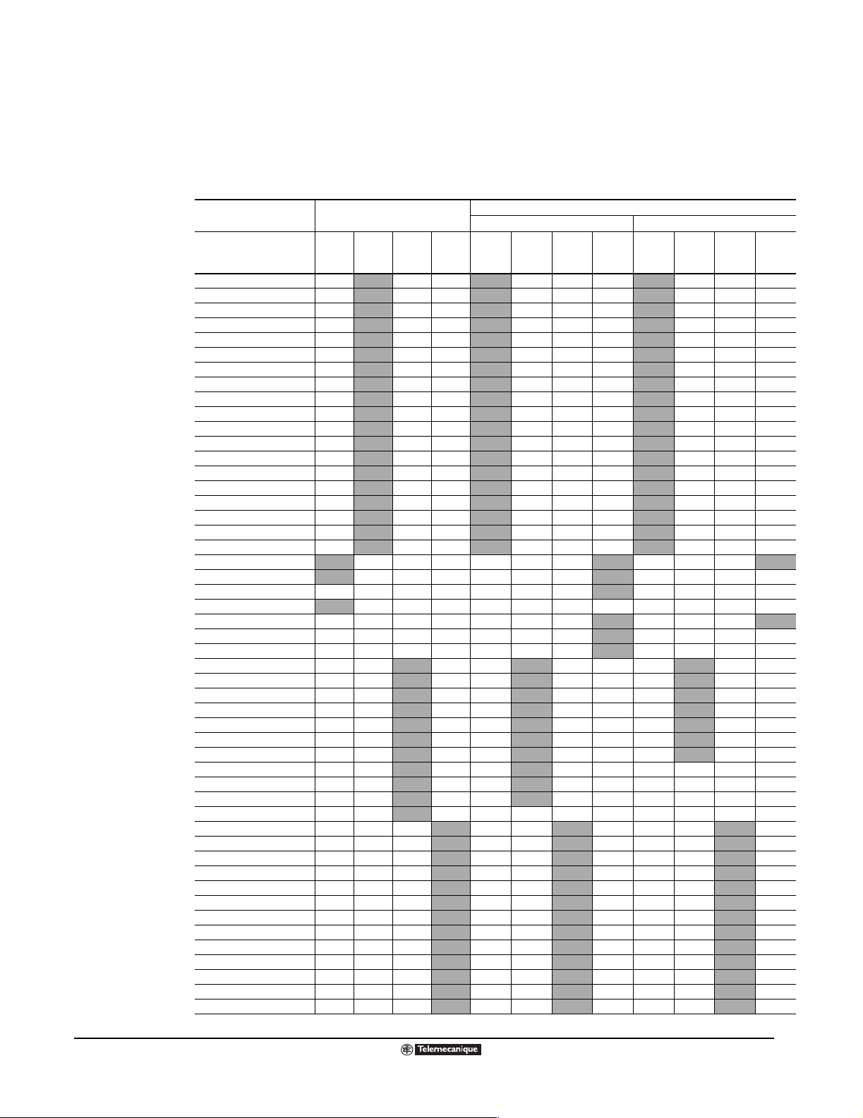
Altivar
®
58 TRX AC Drives
Configurable I/O Functions
• Analog Input 1 (AI1) is configured for 0 to 10 Vdc speed reference input. It is factory-configured to
sum with other analog inputs. AI1 is designated as Speed Reference 1 when Reference Switching
(Hand Auto mode) is configured. AI1 is designated as Set Point Reference when the PI regulator
function is configured.
Possible Assignments
Assignable I/O
on the ATV58 TRX Controller
Function AI2
Reverse Operation
Ramp Switching
Jog Operation
+/– Speed
Setpoint Memory
Preset Speeds
Freewheel Stop
Fast Stop
DC Injection Braking
Motor Switching
Second Torque Limit
Forced Local
Fault Reset
Reference Switching
Auto Tune
PI Auto/Manual
PI Preset Setpoints
External Faults
Torque Limit Switching
Summing Reference
PI Regulator Feedback
PI Manual Speed Reference
Second Speed Reference
Speed Feedback
PTC Motor Probes
Torque Limit (Analog)
Drive Running
Output Contactor Control
Reference Speed Attained
High Speed Attained
Frequency Level Attained
Current Level Attained
Motor Thermal Level Attained
Drive Thermal Level Attained
Loss of Follower (4–20 mA)
Frequency Level 2 Attained
Brake Sequence
Motor Current
Motor Frequency
Ramp Output
Motor Torque
Signed Motor Torque
Signed Ramp
PI Reference
PI Feedback
PI Error
PI Integral
Motor Power
Motor Thermal
Drive Thermal
LI2
LI3
LI4
R2 AO
Assignable I/O with Optional I/O Extension Card
Analog I/O Extension Card Digital I/O Extension Card
LI5
LO AO AI3
LI6
LI5
LI6
LO AO
A+ A–
B+ B–
09/2003
© 2000–2003 Schneider Electric All Rights Reserved
51
Page 52
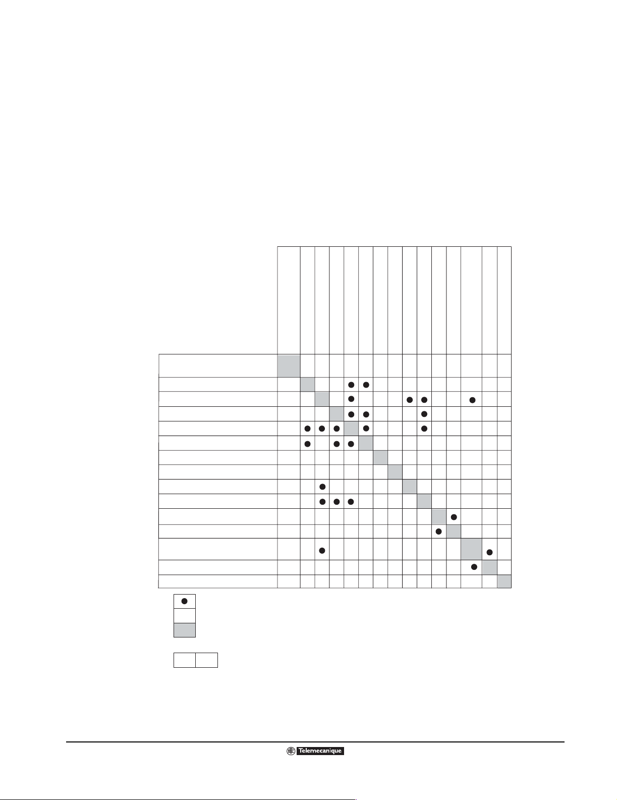
Altivar
®
58 TRX AC Drives
Function Compatibility
FUNCTION COMPATIBILITY
The table belo w shows th e I/O functi ons that are no t compatib le with each other. Any functio n not listed
in this table is compatible with all other functions.
Aside from the particular functions shown in this table, two general priorities exist:
• Stop functions always have priority over Run commands.
• Speed references via logic command always have priority over analog setpoints.
In addition, the choice of functions is limited by:
• The number of controller inputs and outputs to be re-assigned.
• The incompatibility of certain functions with others.
Compatibility Ta ble-add (catalog).eps
Fast stop
Jog
Automatic DC injection braking
Summing inputs
PI Regulator
+Speed/-Speed
Automatic DC injection braking
Summing inputs
PI Regulator
+Speed/-Speed
Reference switching (Auto/manual)
PI regulator with Auto/manual
Freewheel stop
Fast stop
Jog
Preset Speeds
Reverse operation
Inhibit reverse operation
Speed regulation with
tachogenerator or encoder
Torque limitation via AI3
Torque limitation via LI
Incompatible functions
Compatible functions
No significance
Function priority (functions which cannot be active at the same time):
➞
The stop functions have priority over run commands.
The speed references from a logic command have priority over analog references.
Note: An incompatible function must be deselected before the desired function can be programmed.
For example, if preset speeds is programmed, it must be cleared before the +/- speed parameter
can be selected.
The arrow points to the function that has priority.
➞
➞➞
Freewheel stop
Reference switching (Auto/manual)
PI regulator with Auto/manual
Preset Speeds
➞➞
➞➞
➞➞
Reverse operation
Inhibit reverse operation
Speed regulation with
tachogenerator or encoder
Torque limitation via AI3
Torque limitation via LI
52
© 2000–2003 Schneider Electric All Rights Reserved
09/2003
Page 53

d
or
se
t
)
0
ec
cc
ec
SP
q
p
tm
)
d
or
se
g
0
0
Altivar
®
58 TRX AC Drives
Assignment of Logic Inputs (LIx)
ASSIGNMENT OF LOGIC INPUTS (LIx)
The follo wing s ections des cribe the poss ible a ssignments of the L ogic Inputs
f(Hz
H
Acc 2D
1D
A
s
(LIx) on the drive control ler and the optional I/O Extension Cards . Logic Input
Red.e
or
2
1 (LI1) is configured for Run Forw ard w hen the drive controller is set for two
wire control and con figured f or ST OP when the driv e controller is set f or three
1
wire control. In three wire control, Run Forward requires a logic input. Run
Reverse, if used, requires another logic input.
Forwar
Rever
1
LI4
0
Acceleration 1/Deceleration 1: Ad justmen t 0.0 5 to 9 99.9 s, preset at 3 s
Acceleration 2/Deceleration 2: Ad justmen t 0.0 5 to 9 99.9 s, preset at 5 s
t
t
Ramp Switching Timing Diagram
f (Hz
Forwar
Rever
Jo
Jog Speed Timing Diagram
Motor
Frequency
LSP
0
LSP
Forward
2nd action
1st action
Reverse
2nd action
1st action
bb
aaa a a a a
0
0
cc
d
+ Speed Timing Diagram
ATV58 terminal strip
LI1
LIy
LI1: Forward
LIx: Reverse
LIy: +Speed
LIx
a c max. speed reference
+ 24 AIX
bd
Activate a or c, then
activate b or d.
+ Speed Wiring Example
Reverse Operation
A logic input is assigned to reverse the direction of operation. The factory
default is for logic input LI2 to be used to reverse operation. To disable this
function (for example, when using the controller with a single-direction
motor), configure for no assignment or re-assign LI2 to another function.
Alternate Ramp Switching
Alternate ramp switching allows switching between two sets of acceleration
and deceleratio n ramp times, w ith each set being adju sted separately. A logic
input can be assigned to switc h between th e two sets . A frequency thresho ld
may also be configured for ramp switching; see page 45.
Ramp switching is particularly suited for the following:
JogOp.eps
• Material handling appli catio ns that re quire s mooth st arting and approac h.
• Applications involving fast, steady-state speed correction.
• High-speed lathes with limitation of acceleration and deceleration above
certain speeds.
An example of using a logic input (LI4) to switch between two sets of ramps
is shown to the left.
Jog Speed
This function pulses motor operation using minimum ramp times (0.1 s),
limited speed, and delay time between two pulses. To use this function,
assign a logic input to jog. Jog direction is provided b y the oper ating direction
command. This function is particularly appropriate for the following
applications:
• Machines requiring some manual operation during the process.
• Gradual advancement of equipment during a maintenance operation.
The graph to the left portrays a typical jogging operation. The speed
reference adj usts bet ween 0 and 10 Hz (pres et at 10 Hz) and the del a y (tm)
between jog pulses adjusts from 0 to 2 s (preset at 0.5 s).
+Speed double action (catal og).eps
+ Speed
This function is also referred to as the motorized potentiometer function. It
allows the spee d reference to be increased using one logic signal. The speed
is maintained when the + speed input is opened. The maximum speed is
given by the reference applied to the anal og inputs. F or example , connect AI1
to +10 Vdc. To use this function, one or two logic inputs m ust be re-a ssigned.
This function is appropriate for:
• Applications involving centralized control of a machine composed of
several sections operating in one direction.
• Controlling a material handling crane operating in two directions with a
+_- Speed Double Action.eps
pendant control station.
Examples of this function are shown in the illustration to the left.
09/2003
© 2000–2003 Schneider Electric All Rights Reserved
53
Page 54
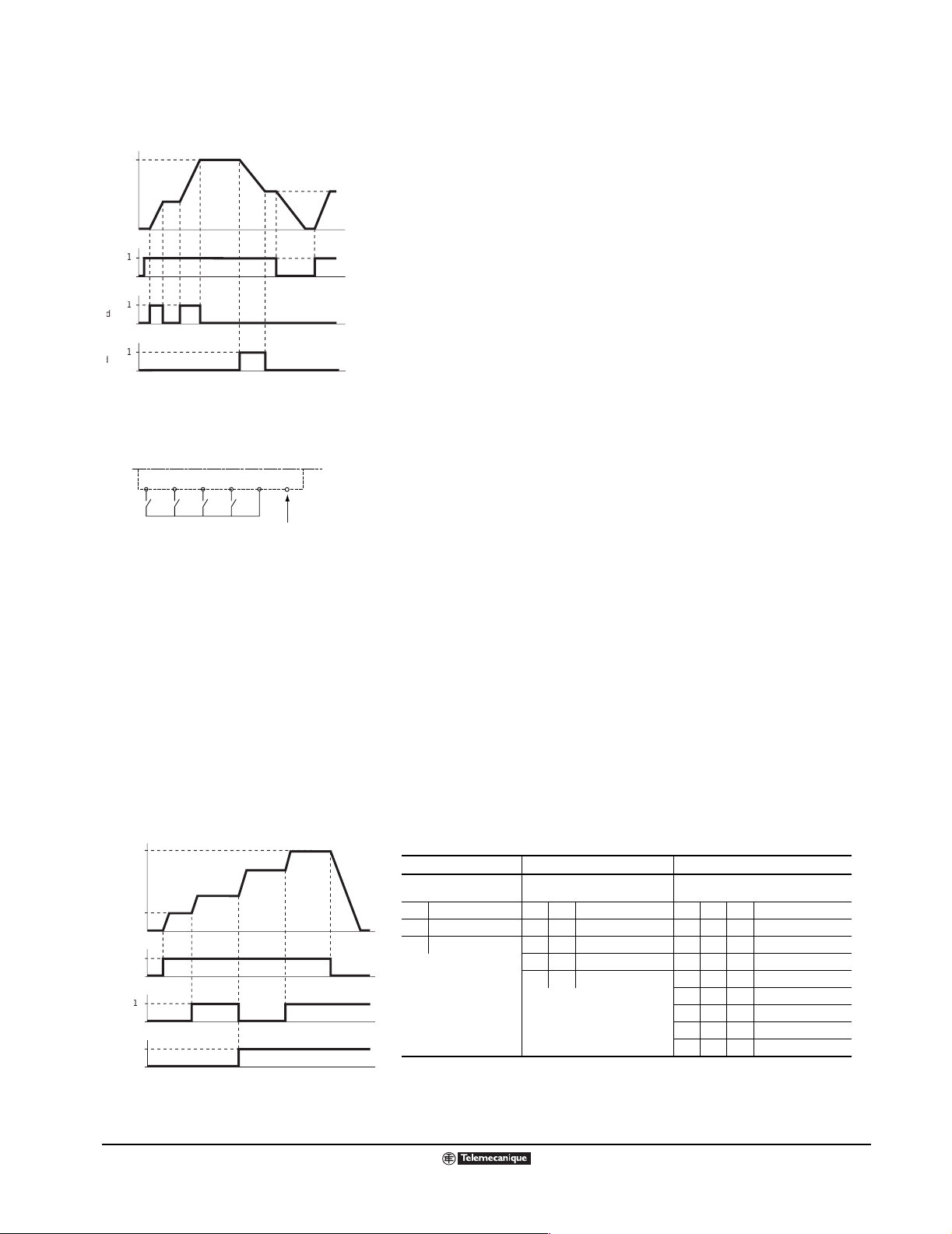
(Hz)
t
t
t
t
d
or
s
e
d
d
Speed
0
0
0
Mi
E
p
SP
)
d
or
se
0
SP
Altivar
®
58 TRX AC Drives
Assignment of Logic Inputs (LIx)
Forwar
Rever
Spee
-
+/- Speed With Saving the Last Reference
Timing Diagram
+/– Speed
s
x1.e
nus
us
This function may also be referred to as the motorized potentiometer
function. It allows the speed reference to be increased or decreased using
one or two logic s ignals , with or w ithout s aving th e last ref ere nce spee d. The
maximum speed is given by the reference applied to the analog inputs. For
example, connect AI1 to +10 Vdc. To use this function, two or three logic
inputs must be re-assigned.
This function is appropriate for:
• Applications involving centralized control of a machine composed of
several sections operating in one direction.
• Controlling a material handling crane operating in two directions with a a
pendant control station.
Two examples of this function are shown at the l eft.
Setpoint Memory
I1: Forward
I2: Reverse
I3: +Speed
I4: -Speed
ATV58 TRX terminal
LI1 LI2 LI3 LI4 +24 AIX
a b A B
Max. speed
+/- Speed Wiring Example
f (Hz
H
L
Forwar
Rever
LI2
LI3 0
1
LI4 0
Preset Speeds Timing Diagram
Activate input
a or b, then
activate input
A or B.
This function is associated with the +/– Speed function, and determines
whether the speed reference level is read and stored upon loss of the Run
signal or the mains supply. The stored reference is applied to the next Run
signal. The function may be set to either Yes (store reference signal) or No
(do not store reference sig nal ).
+Speed_-Speed Wiring (catalog).eps
Preset Speeds
The Preset Speeds function allows switching between 2, 4, or 8 preset
speeds, and requires 1, 2, or 3 logic inputs respectively. The function is
typically used with materials handling and machines with several operating
speeds. A typical example involving four speeds is shown to the left.
In this exam ple , four speeds are obta ined wi th inp uts L I3 and LI 4. At st ate 0,
the speed is LSP or the speed reference depending on the level of analog
inputs AI1 and AI2. The preset speeds may be adjusted from 0.1 Hz to the
maximum frequency. The factory default settings are:
• 1st Speed: LSP or reference.
• 2nd Speed: 5 Hz.
• 3rd Speed: 10 Hz.
• 4th Speed: HSP
Preset Speed Logic
2 Preset Speeds 4 Pres et Speeds 8 Preset Speeds
PresetSpds.eps
Assign LIx to PS2. Assign LIx to PS2, then LIy to PS4.
LIx Speed reference LIy LIx Speed reference LIz LIy LIx Speed reference
0LSP + AI reference00LSP + AI reference000LSP + AI reference
1 HSP 0 1 SP2 0 0 1 SP2
1 0 SP3 0 1 0 SP3
11HSP 011SP4
Assign LIx to PS2, then LIy to PS4, then
LIz to PS8.
100SP5
101SP6
110SP7
111HSP
NOTE: To reassign the logic inputs to a function other than Preset Speeds,
PS8 (LIz) must be cleared, then PS4 (LIy), then PS2 (LIx).
54
© 2000–2003 Schneider Electric All Rights Reserved
09/2003
Page 55

(
)
Altivar
®
58 TRX AC Drives
Assignment of Logic Inputs (LIx)
Hz
123 4
1 = Fast Stop
2 = DC Injection Braking
3 = Normal stop on dec. ramp
4 = Freewheel Stop
Controlled Stop
Diagram
Controlled Stop Functions
The Controlled Stop functions provide alternate stopping methods to the normal drive controller stop.
CntrlStop.eps
Normally , the d rive controll er follo ws the decele ration ra mp on a comm and to stop . To use the Controlled
Stop function, one logi c input (LI) must be assig ned. The input is activ e at state 0 (open) f or a F reewheel
Stop or Fas t Stop, and is activ e at state 1 (closed ) for DC Inje ction Brak ing. These stop requ ests alw ays
have priority over a normal stop or a Run signal. Three controlled stop methods are available:
• Freewheel Stop/Run Permissive
The drive controller output is turned off and the motor coasts to a stop according to the inertia and
resistive torqu e of the loa d. This method i s often used in appl icati ons w here Run Permissive is use d
as an electrical safety device.
•Fast Stop
Braking with decele r atio n ramp time divided by a coefficient adju st able from 1 to 10. This m eth od is
often used for materials handling applications and provides the quickest way to stop without
additional hardware.
• DC Injection Braking
Adjustment of time (0 to 30 s , preset at 0.5 s) and current (10% to 136% o f nominal controll er current
in a high-torque appli cation, pres et at 70%). It is poss ible to s et continu ous brakin g current from 10%
to 100% of nominal motor c urrent (f a ctory setting i s 50%). After 30 s, the curre nt autom atica lly go es
to 50%. This method is often used for app li cat ions invol vi ng fans since it el im ina tes th e ne ed for the
addition of a braking resistor.
Note that after a stop (frequency less than 0.1 Hz), DC Injection Braking may be combined with the
other methods. For this situation, only the current injected after 30 s can be adjusted.
Switching Between Two Motors
This function all o w s a si ngl e drive controller to co ntro l t w o m oto rs w ith di fferent power ratings, on e at a
time. Activ ating this pa rameter auto matically s cales the DC in jection curre nt, brak e release c urrent, and
nominal motor current based on a programmable scaling factor and the larger motor parameters that
have been configured. This function inhibits motor thermal protection of the second motor. External
contactor control f or both mo tors and e xternal motor thermal pro tection f or the seco nd motor is requir ed
for using this function.
Freewheel Stop Below Selectable Frequency
This parameter allows the drive controller to freewheel stop below a programmable frequency. After a
stop command is received and the drive has followed the deceleration ramp to the programmed
frequency, the d rive contro ller output is turned off and the mot or coasts to a stop according to the inertia
and resistive torque of the load.
Torque Limit by Logic Input (Constant Torque Rated Products)
This function allows a logic input to be assigned a second level of torque limit. The associated torque
level is factory set at 200% and is adjustable from 0-200% of the drive controller constant torque rating.
When the assigned lo gic input is closed (set t o state 1) the max imum torqu e is limite d to the configu red
value. This feature can be used in the following type of applications:
• At the end of a material handling cycle when it may be useful to stall the motor as the load meets a
barrier.
• Cut-to-length applic ations with the material stoppe d while main taining some m otor torque to hold the
material.
09/2003
© 2000–2003 Schneider Electric All Rights Reserved
55
Page 56
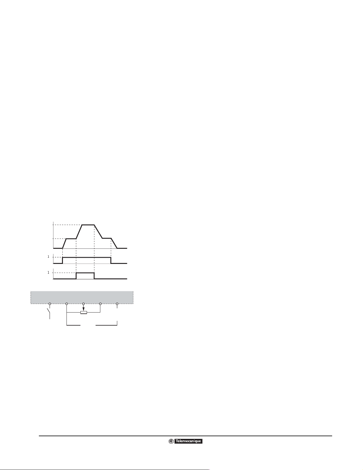
)
d
se
0
p
g
Altivar
®
58 TRX AC Drives
Assignment of Logic Inputs (LIx)
Forced Local
This function allows a logic input to be assigned to force local control of the
drive controller. Configuration of this function is recommended when using
serial communicatio n with the driv e controller . This inpu t is typically wire d into
the Hand and Off positio ns of a Ha nd-Off- A uto se lect or s wit ch wh en use d in
conjunction with se rial communication with the driv e controller . Assigning this
parameter provides terminal block control when the logic in put is closed
(state 1). Initiating this input overrides any commands being received over
the serial communicatio ns link and the driv e controller respon ds to the inputs
given at the co ntrol terminal block . Parame ter data can still be m onitored ov er
the serial communication link.
Fault Reset
This function allows faults to be reset by a logic input assigned to this
function. Two types of reset are available. See page 66 for fault reset types.
External Fault
This function allows a logic input to be assigned to receive an external
contact closure to stop the drive cont roller and motor . The driv e controller wi ll
stop according to the co ntro lle d s top c on f ig ur ati on. This function is us eful in
applications where interloc king of vario us equipm ent and the driv e contro ller
is required.
f (Hz
Forwar
Rever
LIx
Connection Diagram for Reference Switchin
10
+ 24 V
LIx
COM
AI1
+–
Remote
Signal
+
AI2
0-20 mA
4-20 mA
20-4 mA
Reference Switching Timing and Wiring
Diagrams
s
efSwitch.e
Reference Switching (Auto – Manual)
The Reference switching function permits switching between two analog
references by logic command. This function avoids switching of low-level
speed reference signals by other means, and enables the two reference
inputs AI1 and AI2 to be independent. To use this function, one logic input
(LI) must be re-assigned.
This function is typically used for:
• Machines with automatic/manual operation such as pumps
• Automatic c ontrol via a sensor on input AI2, v alidate d by th e logic inp ut at
state 0
• Manual control via potentiometer on input AI1 (local control)
A graphical representation of reference switching and a connection diagram
are shown to the left.
Auto Tune
This parameter causes the driv e controller to auto tun e the connected motor .
When Auto Tune is initiated, the driv e controll er pulses the conn ected mo tor ,
and measures and st ores m otor s tator re sista nce a nd co nducto r re sista nce.
This allows the drive to pro vi de bett er current regu lation for improved motor
torque performance . Auto Tune can be initiated from the keyp ad or by a lo gic
input assigned to this f unctio n. If an o utput c ontact or is us ed, it i s nece ssary
to close the contactor before the auto tune function is initiated.
56
© 2000–2003 Schneider Electric All Rights Reserved
09/2003
Page 57
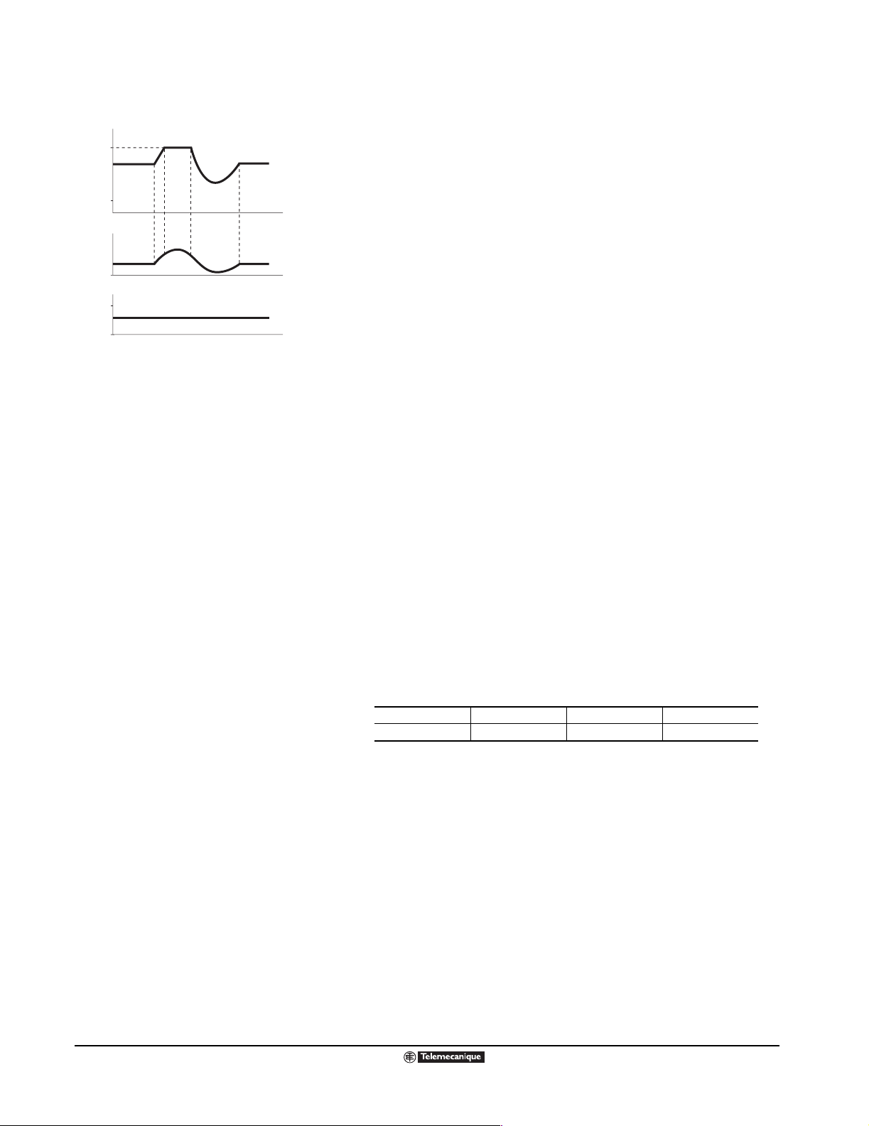
)
SP
SP
0
3
p
p
Altivar
®
58 TRX AC Drives
Assignment of Analog Inputs (AIx)
f (Hz
H
L
AI2 or AI
1
s
uts.e
umIn
Speed Reference Summing Diagram
ASSIGNMENT OF ANALOG INPUTS (AIX)
The following sections describe the possible assignments of the Analog
Inputs (AIx) on the drive controller and the optional I/O Extension Cards.
Speed Reference Summing
Analog input AI2 (and/or analog input AI3 with an I/O e xtension c ard) can be
assigned as a summing in put f or AI1 with peak limiting c orrespo nding to the
speed HSP. This is often used for machines whose speed is controlled by a
correction signal on input AI2.
The figure to the left provides a graphical depiction of summed references.
PI Regulation
The PI Regulation function provides simple regulation of flow rate or pressure
with a setpoint input and a sensor sending a feedback signal to the drive
controller . This fu nction is o ften used f or pump ing and f an appl ications . Note
that the PI Regulation function is not co mpatib le with th e Preset Spe eds and
Jog functions.
The accelerat ion (A CC) and dec eleratio n (dEC) ra mps default to line ar ramp
type even if the ramps had been configured for S ramp or U ramp.
PI regulator can be used with a logic input configured for PI Auto/Manual
mode of operation when the analog option card is used. When the PI
regulator is confi gured and a lo gic input is co nfigured f or PI A uto/Man ual, the
PI regulator function is active in Auto mode and AI3 is used for speed input
in Manual mode.
Logic inputs can be used with the PI regulator to command the drive
controller to run from the analog reference, run at process maximum, or
operate with two other def inable preset setpoints. The configurab le setpoints
can be used to provid e two di ff e rent setp oints f or two di ff e rent proc esses , or
they can be used instead of using AI1 for setpoint input. For example,
providing a setpoint via the logic inputs can eliminate the need for a
potentiometer.
09/2003
Four analog outputs are available to monitor various aspects of the PI
regulator function. See page 63 for more information.
PI Setpoint OPS PI Feedback OPF
PI Error OPE PI Integral Error OPI
© 2000–2003 Schneider Electric All Rights Reserved
57
Page 58

Altivar
®
58 TRX AC Drives
Assignment of Analog Inputs (AIx)
The following figure shows a diagram of the PI Regulator inputs, calculation points, and outputs.
PI setpoint input AI1
or via a configured
setpoint
PI
feedback
Input AI2
PSP
Time constant filter
Manual speed regulation input AI3 (PIM)
FBS
10
Multiplier
PI
inversion
+
PIC
X
±1
–
PI regulator
rPG
rIG
Ramp
if PSP > 0
ACC
dEC
X
AC2
dE2
Run
command
Ramp
PI Auto/man selection by Logic Input (PAU)
The following table provides a descripti on of the inputs to the PI Regulator.
Input Range Description
The setpoint to the PI regulator can be provided from one of three sources:
PI setpoint
PI feedback
Auto / Manual with
manual speed Input
— via analog input, AI1 (AI2 and AI3 can be set to sum with AI1)
— via preset setpoints defined by logic inputs (see Preset setpoints in this table)
— over a communication network
The feedback to the PI regulator can be provided from AI2 (0–20 mA signal) or AI3 (0–10 Vdc
voltage signal).
When the PI regulator is configured and a logic input is configured for Auto / Manual, AI3 is the
speed input in manual mode. The PI regulator function is active in Auto mode. When the logic
input is open, (set to state 0), Manual mode is active and the PI regulator is active.
Auto mode is active when the logic input is closed, (set to state 1). In manual mode AI3 is
enabled and the drive controller responds proportionally to the speed reference at AI3.
Ramp
if PSP = 0
ACC
dEC
Reference
Auto
Man
Preset setpoints
PI Inversion Yes/No
PI proportional gain 0.01–100 PI regulator proportional gain adjusts the scaling of the PI setpoint signal.
PI integral gain 0.01–100 s PI regulator integral gain adjustment.
Time-constant
feedback filter
PI feedback scaling 1.0–100
58
© 2000–2003 Schneider Electric All Rights Reserved
0–100% of
process
maximum
0–10 s
Logic inputs can also be used to provide programmable setpoints. Two or four preset setpoints
require the use of one or two logic inputs respectively.
2 preset setpoints 4 preset setpoints
LIx Reference LIy LIx Reference
01Analog reference
Process max. (HSP)00
PI inversion permits an inverted, or
No, the motor speed increases when the error is positive. If PIC = Yes, the motor speed
decreases when the error is positive.
PSP can be use d to dampen the feed back sig nal. If PSP is set to zero, the ACC and dEC ramps
are active. If PSP is > 0, the AC2/dE2 ramps are active. Adjustment of AC2/dE2 can be used to
refine the response of the PI loop. The dEC ramp is used on stopping.
PI feedback scaling allows adjustment of the maximum value of the PI feedback signal so that
it corresponds to the maximum value of the PI regulator speed reference.
0
Analog reference
1
1
1
PI2 (adjustable)
0
PI3 (adjustable)
1
Process max. (HSP)
reverse-acting, response to the PI setpoint signal. If PIC =
09/2003
Page 59

AA –
COM + 24
r
d
der
d
Altivar
®
58 TRX AC Drives
Assignment of Analog Inputs (AIx)
NOTE: Unlike the
previous assign ments ,
which may be
assigned to either the
analog or digital I/O
extension cards, the
follow i ng as sig nm ents
can only be assigned
to the A+,A–,B+,B–
terminals on the digit al
I/O extension card.
Encoder Speed Feedback
The Encoder Speed Feedback function can be used to improve the speed regulation based on the
encoder f eedback s ignal. It is intended f or use in applic ations in wh ich the loa d on the mo tor is ch anging
but accura te speed reg ulation is critical to the p rocess . The spee d fe edbac k input to the drive controller
is 24 Vdc. A choice of two different types of encoders can be configured as speed feedback: a NPN
sensor type, or a quadrature type encoder.
The NPN sensor type is for use in applications in which the sensor is detecting teeth on a wheel. The
24 Vdc supply on th e option card can be us ed to p o wer the NPN senso r. The qua drature encoders are
usually mounted to the motor shaft. An e xt ernal 24 Vdc pow er supply f or the e ncoder is recom mended.
Selection of the encoder is critical for obtaining desired speed regulation.
The NPN sensor type encoders can improve the speed regulation from ± 1% to ± 0.5% of motor rated
speed. The quadra ture type en coder can i mprov e the speed regulation to ± 0.02% of rated moto r speed
with a 1024 pulse count encoder.
The maximum signal frequency input with this option card is 33 kHz. Higher pulse count encoders
provide greater accuracy. The pu ls e cou nt m u st be co nfigured in the drive contro lle r. Use the following
to assist in selecting an encoder.
1. Determine the maximum allowable pulse count (pulses per revolution, line count, encoder
resolution) with the following formula.
Max. allowable pulse count
33,000 (max. signal frequency)X60 (seconds/minute)
--------------------------------------------------------------------------------------------------------------------------------------------- -=
Motor RPM @ drive controller maximum frequency
2. When selecting an incremental encoder: use an encoder with a pulse count closest to, but not
greater than, the result of the calculation in step 1. This will result in the highest precision.
3. When selecting a NPN sensor , choose a device that will li mit the pulse count to the v alue dete rmined
in step 1. Mechanical play in the toothed wheel or other device will degrade the resulting precision.
4. The maximum pulse frequency of the sensor must not be exceeded. Generally, it is this parameter
that limits precision. As an example, the pulse count of a sensor with a maximum frequency of
2000 Hz on a motor with a top speed of 1800 RPM is:
66 Pulses per revolution
2000 (max. signal frequency)X60 (seconds/minute)
----------------------------------------------------------------------------------------------------------------------------------------------------------=
1800 (Motor RPM @ drive controller maximum frequency)
Example
09/2003
• Motor nominal RPM =1800@ 60 Hz.
• Drive controller maximum frequency = 63 Hz.
• Motor nominal RPM @ 63 Hz = 1800 x (63/60) = 1890
• Maximum pulse count = 33,000 x 60 / 1890 = 1047
• Any pulse count of 1047 or less will work. The higher the pulse count, the higher the feedback
Examples of the speed fee db ack function are shown belo w.
resolution. The nearest standard encod er puls e cou nt les s than the abo ve calculation is 1024.
Example 1: Use of Incremental Speed Feedback in one
operating direction with an inductive sensor or
photoelectric detector. This provides simplified regulation,
but is less accurate at low speed.
Option
ar
enso
Example 2: Use of Incremental Speed Feedback in two
operating directions with an incremental encoder. This
provides more accurate regulation than a NPN sensor.
Option
ar
COM
IncrSpdEx1.eps
Incremental
© 2000–2003 Schneider Electric All Rights Reserved
nco
external 24 VDC
power supply
IncrSpdEx2.eps
0
+ 24 V
59
Page 60

AI3B
AI3A
B
R1 R2
d
r
0
e
f
r
Altivar
®
58 TRX AC Drives
Assignment of Analog Inputs (AIx) With Analog I/O Extension Card
Incremental Speed Reference
This function assigns encoder inputs used for the Encoder Speed Function to the “summing input”
function. It is useful for the following applications requiring speed synchronization of several motors.
ASSIGNMENT OF ANALOG INPUTS (AIx) WITH ANALOG I/O EXTENSION CARD
The follo w in g i s a description of the pos sible assignments o f th e An alo g I npu ts (AIx ) w he n th e opti ona l
Analog I/O Extension Card is added to the ATV58 TRX drive controller.
Tachometer Speed Feedback
The Tachogenerator Speed Feedback function can be used to improve the speed regulation based on
the tachometer feedback signal. It is intended for use in applications in which the load on the motor is
changing but ac curate speed regu lation is critical to the process. The tac hometer can impro ve the speed
regulation from ±1% to ±0.1% of motor rated speed.
The voltage of the tachogenerator at maximum speed must be between 5 and 9 volts. An accurate
setting for adjusting this value can be found in the Adjust menu. If necessary , an e xternal divider bridge
may be used to set this value (as shown to the left).
As an example of setting the value , assume a motor is turning at 1 500 rpm at 50 Hz, the t achogenera tor
is 0.06 V/rpm, and the maximum speed is set at 75 Hz (2250 rpm). Then:
• The maximum voltage is 0.06 x 2250 = 135 Vdc.
• The recommended current for the tachogenerator is 10 mA, so
R1 + R2 = 135/0.01 = 13.5 kΩ.
• The average voltage on the input is 7 V, thus R1 = 7/0.01 = 700 Ω or
680 Ω (nearest standard value).
• R2 = 13.5 – R1 = 13.5 – 0.7 = 12.8 or 12 kΩ (nearest standard value).
• Exact voltage on AI3 = 135 x R1/(R1 + R2) = 135 x 0.68/12.68 = 7.24 V.
Use resistors with suff icien t po w er (2 W minim um ). Exac t scali ng of s peed f eedb ac k is to be perf o rmed
by programming at the time of installation.
Use of a Divider Bridge for Speed Feedback with Tachogenerato
Option
r
SpdFeedbk.eps
Thermo Temperature Probe (PTC)
See the motor protection section on pag e 48.
Torque Limit by Analog Input (on Constant Torque Rated Products)
Analog input AI3 may be assigned to this function to allow the amount of torque to be reduced. An I/O
extension card w ith an alo g i nput must be insta lle d a nd a logic input mu st be as sig ned to torque limit to
use this function. This function is very useful for applications where torque or traction needs to be
corrected. The graph below shows how the torque varies as AI3 varies between 0 and 10 Vdc.
1
TorqRed.eps
If the logic input is at 0, the torque is lim ite d by the setting of the
Torque Limit parameter. If the logic input is at 1, the torque is
limited by the analog input assigned to this function.
Internal Limit o
ATV58 Controlle
60
© 2000–2003 Schneider Electric All Rights Reserved
Torqu
09/2003
Page 61

Altivar
®
58 TRX AC Drives
Assignment of Logic Outputs (R2 or LOx)
ASSIGNMENT OF LOGIC OUTPUTS (R2 OR LOx)
The following is a description of the possible assignments of the Logic Outputs (R2 or LOx) on the
ATV58 TRX drive controller and the optional I/O Extension Cards.
Drive Running
The logic output is hig h (state 1, 24 Vdc nominal) if the motor is dr awing current, or if a run co mmand is
generated with a zero speed reference.
Output Contactor Control
The Output Contactor Control function enables the ATV58 TRX drive controller to control a contactor
located between the drive and the motor. The request to close the contactor is made when the Run
signal is given. The request to open the contactor is made when the Run signal is removed and the
deceleration ramp is completed.
The function is for use in applications where an air gap opening in the motor circuit is required. The
connection method illustrated in the diagram below is required.
This function may also be used:
• For applicat ions i n v olvi ng machi nes w here the oper ation re quires pow er to the m otor to be remo v ed
when there is a stop to prevent any possibility of an untimely restart (for example, a materials
handling carousel where items are put down and then picked up manually).
• T o im plement a driv e controller b ypass circuit and to allow ac ross-the-line o peration of the motor . The
contactor on the drive controller is open in bypass mode to prevent applying line side power to the
output of the drive controller.
LineCont.eps
KM2
U
U1
3 Phase
V
W
KM2 TS
V1
W1
M
TS = Transient suppressor
◆ See Specifications section for
contact or rating s.
R2A
◆
R2C
120 VAC
Wiring Diagram for Output Contactor
Reference Frequency Attained (Speed Attained)
The logic output is high (state 1, 24 Vdc nominal) if the output motor frequency is equal to the speed
reference value.
High Speed Attained
The logic output is high (state 1, 24 Vdc nominal) if the outpu t motor frequency is eq ual to the high-speed
value.
Frequency Threshold Attained
The logic output is hi gh (state 1, 24 Vdc no minal ) if the outpu t motor fre quenc y is g reater tha n or equ al
to the configure d frequen cy thres hold. The frequ ency thr eshold i s f actory set at 50 o r 60 Hz ( depend ing
on the position of the 50/60 Hz switch) and has an adjustable range of low speed to high speed. Two
different levels can be configured to correspond to two logic output assignments.
09/2003
© 2000–2003 Schneider Electric All Rights Reserved
61
Page 62
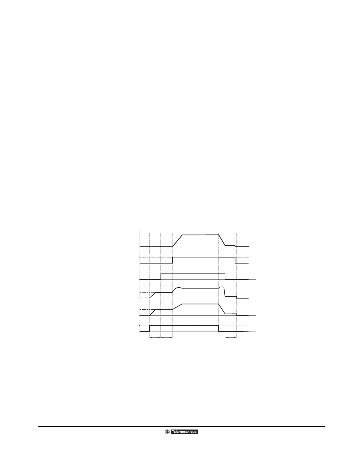
Altivar
®
58 TRX AC Drives
Assignment of Logic Outputs (R2 or LOx)
Current Level Attained
The logic output is high (state 1, 24 Vdc nominal) if the motor current is greater than or equal to the
configured current level. The current level is factory set at 136% and has an adjustable range of 25 to
136% of the drive controller’s constant torque rating.
Motor Thermal Level Attained
The logic output is high (state 1, 24 Vdc nominal) if the motor thermal state is greater than or equal to
the configured motor thermal lev el. The motor th ermal lev el is fac tory set at 100% and has an adjustab le
range of 0 to 118%.
Drive Thermal Level Attained
The logic output is high (state 1, 24 Vdc nominal) if the drive thermal state is greater than or equal to
the configured drive thermal level. The drive thermal level is factory set at 105% and has an adjustable
range of 0–118%
Loss of Follower (4–20 mA Signal)
The logic output is high (sta te 1, 24 Vdc nomin al) if t he signal on the 4–20 mA spee d reference input is
less than 2 mA.
NOTE: Unlike the
previous
assignments, which
may be assigned to
either relay R2 or o ne
of the logic outputs
(LOx), Brake Logic
Command can only
be assigned to relay
R2.
Brake Logic Command
This is a set of parameters that allows control of a mechanical brake by the drive controller.
The brake release is determined by brake release frequency, brak e release current threshold, and brake
release time delay. The bra k e enga ge is det ermined b y th e bra k e enga ge frequ ency and br a k e enga ge
time.
Motor Speed
Brake state
R2 relay
Motor current
Motor frequency
brL
bEn
Increasing or decreasing
1
0
1
0
Ibr
1
0
T bEt
T = non-adjustable delay
brt
Reference
BrakeCom.eps
Parameters accessible in the Adjust menu:
• Brake release frequency (brL).
• Brake release current (Ibr).
• Brake release time (brt).
• Brake engage frequency (bEn).
• Brake engage time (bEt).
62
© 2000–2003 Schneider Electric All Rights Reserved
09/2003
Page 63

ASSIGNMENT OF ANALOG OUTPUTS (AOx)
Altivar
®
58 TRX AC Drives
Assignment of Analog Outputs (AOx)
Max.
Min.
0 mA
4 mA
Minimum
Analog Output
Ranges
20 mA
20 mA
Maximum
The following sections describe the possible assignments of the Analog Outputs (AOx) on the drive
controller and on the o ptional Extensi on Cards. The a nalog output is a cu rrent output. The m inimum and
AnOutGraf.eps
maximum values are configurable, with a range of 0-20 mA, as shown in the graph to the left.
Motor Current
When configured for motor current, the analog output provides a signal proportional to motor current.
The minimum configur ed val ue corresponds to ze ro, w hile the maximum configured v alue of the analog
output corresponds to 200% of the drive controller’s constant-torque rating.
Output Frequency
When configured for output frequency, the analog output provides a signal proportional to motor
frequency estimated by the drive controller. The minimum configured value corresponds to zero, while
the maximum con figured val ue of the analog output corresp onds to the maxim um frequency settin g, not
the high speed setting.
Ramp Output
When configured f or ramp outp ut, th e ana log o utput pro vides a s ignal propo rtional to the freque ncy the
drive controller is commanding the motor to run. The minimum configured value corresponds to zero,
while the maximum configured value of the analog output corresponds to the maximum frequency
setting, not the high speed setting.
Motor Torque
When configured for motor torque, the an alo g out put p rovides a signal proportional to motor to rqu e as
an absolute valu e. The mi nim um config ured v alu e corres ponds to ze ro , w hile the maxim um con figured
value of the analog output corresponds to 200% of the nominal motor torque.
Signed Motor Torque
When configured for signed motor torque, the analog output provides a signal proportional to motor
torque and provid es an ind ication of bra king torque or mot oring torque . The m inim um confi gured v a lue
corresponds to 200% of the br aking torque , while the maxi mum val ue of the analog output corresponds
to 200% of the nomina l motor torque. Zero torque cor r es pon ds t o the a verage torque value ([minimum
value + maximum value] divided by 2).
Signed Ramp
When configured for signed ramp output, the analog output provides a signal proportional to the
frequency the driv e co ntro lle r is co mm an din g the moto r to run in the reverse or f orward direction. Zero
frequency correspon ds to:
(minimum val ue + maximu m value) / 2.
The minimum configured value corresponds to the maximum frequency in the reverse direction, while
the maximum configured value corresponds to the maximum frequency in the forward direction.
PI Setpoint
When configured f or PI setpoint, the analog output pro vides a signal proportional t o the PI setpoint being
provided to the drive controller. The minimum configured value corresponds to the minimum setpoint,
while the maximum configured value corresponds to the maximum setpoint.
PI Feedback
When configured for PI feedback, the analog output provides a signal proportional to the PI feedback
being provided to the drive controller. The minimum configured value corresponds to the minimum
feedback, while the maximum configured value corresponds to the maximum feedback.
09/2003
© 2000–2003 Schneider Electric All Rights Reserved
63
Page 64

Altivar
®
58 TRX AC Drives
Assignment of Analog Outputs (AOx)
PI Error
When configured for PI error, the analog output provides a signal proportional to the PI regulator error
as a percentage of the sensor range being used for the PI feedback, (maximum feedback minus
minimum feedback). The minimum configured value corresponds to – 5%, while the maximum
configured value corresponds to +5%. Zero corresponds to (minimum value + maximum value) / 2.
PI Integral Error
When configured f or PI integ r al erro r , the ana log ou tput pro vi des a s ignal proportional to th e PI inte gr al
error. The minimum configured value corresponds to the low speed setting while the maximum
configured value corresponds to the high-speed setting.
Motor Power
When configured for motor power, the analog output provides a signal proportional to power drawn by
the motor . The min imum configured val ue c orre sp ond s to 0% of the motor nominal motor po wer, wh ile
the maximum configured value corresponds to 200% of the motor nominal motor power.
Motor Thermal State
When configured f or motor th ermal state, the analog output p rovides a si gnal proportional to t he thermal
state of the motor calculat ed b y the driv e con troller. The minim um configu red v alu e corr espon ds to 0%
of the motor thermal state, while the maximum configured value corresponds to 200% of the motor
thermal state.
Drive Thermal State
When configured f or drive thermal sta te, the analog output provid es a signal proportional to the thermal
state of the drive controller. The minimum configured value corresponds to 0% of the drive controller
thermal state, whil e the maxim um c onfigured val ue corres ponds to 200% of the driv e control ler thermal
state.
64
© 2000–2003 Schneider Electric All Rights Reserved
09/2003
Page 65
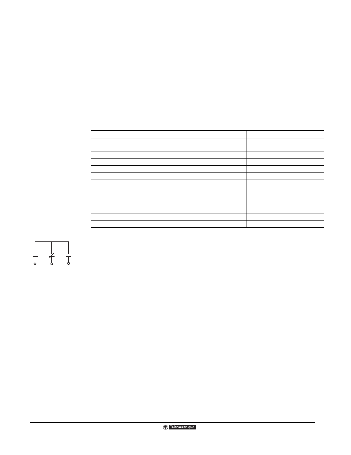
Altivar
®
58 TRX AC Drives
Fault Management Parameters
FAULT MANAGEMENT PARAMETERS
The ATV58 TRX drive is equipped with features that are designed to protect the drive controller and
motor , and to provide p roc es s rela ted information. Un de rsta ndi ng the fault m ana ge ment capabilities o f
the drive controller and determining the proper configuration for the application can enhance the total
system installati on and perf ormance ov er the lif e of the eq uipment. T he f ault mes sages pro vided b y the
drive controller can be divided into three categories:
• Protective f aults are di splay ed when the drive d etects conditions that may da mage the drive c ontroller
and/or motor. The drive controller shuts down to prevent further damage from occurring.
• Drive faults ar e displayed when a problem in the drive needs to be diagnosed.
• Process faults are displayed when a process signal used by the drive controller is interrupted.
Fault Messages
Protective Faults Drive Faults Process Faults
Input phase loss Precharge fault Loss of 4-20 mA signal
Undervoltage EEPROM fault Loss of RS-485
Overvoltage Internal fault External fault
Drive overheating Internal communication fault Speed feedback fault
Motor overload Power rating error Communication network fault
Overbraking Option error
Motor phase loss Option removed
Overcurrent EEPROM checks
Motor short circuit
Motor overheating
Thermal sensor fault
Overspeed
Ramp not followed
Fault Relay.eps
R1A R1B R1C
Fault Relay Diagram
Fault Relay
The fault re lay (R 1) provi des 1 normally op en and 1 normally closed con tact. The rela y is energize d and
the state of the contacts re v erses when th e drive c ontroller is pow ered up and a fa ult is not pres ent. This
relay cannot be re-assigned.
Resetting a Fault
The drive controller can be reset after a fault by one of three methods:
• Turning power to the drive controller off, wait for the LEDs to go off, and apply power.
• Using the reset b utton on t he k e ypa d, if pro gr amme d for local control, or b y a l ogic i nput a ssign ed to
Faul t Reset.
• By the Automatic Restart function if configured.
Automatic Restart
This function permits a utomatic restarting after the driv e controller detects a f ault, provided th at the other
operating func tions are cor rect , a Run com mand is pre sent, and the f aul t has d isapp ear ed. The f acto ry
setting for thi s function is NO . Th e num ber of resta rt attempts and the delay between these attempt s is
selectable.
When the A uto resta rt is selected, t he f ault rela y rema ins ene rgized so that the driv e con troller do es not
signal a f ault f rom a cond ition fro m which it ma y b e ab le to re start. If the f ault h as dis appeared, the drive
controller will att empt to res tart the motor aft er the d ela y time config ured. T he auto restart dela y t ime i s
factory set at 30 seconds and has an adjustable range of 0.1 to 999.9 seconds. If the drive controller
remains fau lte d afte r atte mp ting the co nfigured number of restarts, the fault relay will the n dee ne rgize.
The drive contro ller must be reset b y cycling po wer afte r the cause of the fau lt has been elim inated. The
number of restart attempts is factory set at 5 and has an adjustable range of 0 to 255.
09/2003
© 2000–2003 Schneider Electric All Rights Reserved
65
Page 66

Altivar
®
58 TRX AC Drives
Fault Management Parameters
The faults which allow automatic restarting are:
• Input mains overvoltage • Drive controller thermal overload
• 4-20 mA speed reference loss • DC bus overvoltage
• External fault • Motor phase loss
• Serial link fault
• Motor thermal overlo ad if thermal state is below 100%
• Mains voltage too lo w (for this faul t, the fun ction is alw a ys active, ev e n if it has not bee n conf igured).
In the case of this fault, the controlle r fault relay re mains energized if the function is configur ed, and
the speed reference and the operating direction must be maintained.
Automatic restart is often used in applications where machines or installations are operating
continuously or wi thout supervision and which, wh en re sta rted, pose no ha za rd to eith er eq uip me nt o r
personnel (for example, pumps, fans, etc.).
Fault Reset Type
This function allo ws f ault s to be rese t by logic i nput (LIx), which ca n be re-as signed t o this funct ion. The
starting conditions after reset are the same as those at a normal power-up.
T w o types of reset are a vail able: Type 1 and T ype 2. In Type 1, which is often used for applications wh ere
drive controllers a re difficult to ac cess (for e xample, on moving p arts in materials handling syste ms), the
following faults may be reset:
• Overvoltage • Overspeed
• External fault • Drive contr oller overheati ng
• Motor phase loss • DC bus overvoltage
• Loss of 4-20 mA speed reference • Serial link fault
• Motor overload if thermal state is below 100%
The mains undervolta ge and mains pha se loss f aults wi ll reset autom atically when the supply ret urns to
normal.
In Type 2, all faults are inhib ite d, i nc lud in g th ermal prote ct ion fun cti ons except motor sho rt-circuit. Thi s
type is used in applications involving drive controllers where restart could be vital, such as furnace
conveyors, smoke extraction fans, and machines with hardening products which need to be removed.
Output Phase Loss
The output phase loss detection can be disabled. Factory setting is enabled.
Input Phase Loss
The input phase loss detection can be disabled on three phase devices. Factory setting is enabled.
Loss of Follower
The drive controller can be configured to detect a loss of a 4–20 mA speed reference signal. If so
configured, the following responses to the loss of signal can be selected:
• Immediate fault, stop the motor
• Stop the motor without fault and restart on return of the reference signal
• Stop the motor, deenergize the fault relay, and display loss of 4–20 mA speed reference on the
keypad display
• Continue to run at last t he speed witho ut fault an d follo w the speed ref erence upon re turn of the signal
• Continue to run, b ut at a c onfigu red pre set sp ee d. The adjus tab le r ange for the preset speed is fro m
0 to the high speed setting.
66
© 2000–2003 Schneider Electric All Rights Reserved
09/2003
Page 67

Altivar
®
58 TRX AC Drives
Fault Management Parameters
Automatic Catch of a Spinning Load (Catch-on-the-fly)
This function, also termed a “fl ying start,” is ac tiv e b y de f ault (a lthoug h it is au tomati cally dis ab led i f the
Brake Sequen ce functio n is con figured ). It allo ws the motor to be restarted without a spee d surge after
one of these events:
• Mains power break or simple switch off.
• Fault reset or automatic restart.
• Free w hee l stop or DC injec tion stop w ith log ic input.
• Momentary loss of power downstream of drive cont roller.
On restart, the controller searches for the effective speed of the motor in order to restart on a ramp from
this speed and return to the reference speed. The speed search time can reach 1 s depending on the
initial difference.
This function is often used for applications where the motor speed of a machine does not drop rapidly
after a mains po wer break (machines with high inertia) as well a s fans and pum ps driven b y residual flux.
Controlled Stop on Power Loss
This function can be used to determine how the drive controller will react to a loss of power. Three
configurations are possible:
• Disabled.
The drive controller im medi ately f a ult s in respons e to an input ph ase los s. This is the f a ct ory setting.
• Follow the programmed deceleration ramp until motor stops or undervoltage fault appears.
Use this configuration if a consistent deceleration ramp is more important than maximizing power
loss ride through.
• Maintain DC bus voltage.
With this configuration, DC bus voltage is maintained as long as possible. The ATV58 TRX drive is
designed to ride through power s ags and to pro vide deg raded ope ration do wn to 60% o f nominal lin e
voltage for 500 ms. Longer ride through is possible if there is sufficient kinetic energy generated by
the connected motor load inertia. An undervoltage fault appears after the voltage drops below 60%
of nominal line voltage. This configuration should be used to maximize the ride through time of the
drive controller and to minimize nuisance tripping.
09/2003
© 2000–2003 Schneider Electric All Rights Reserved
67
Page 68

Altivar
®
58 TRX AC Drives
Additional Functionality Provided in the ATV58 Type FVC Drive
ADDITIONAL FUNCTIONALITY PROVIDED IN THE ATV58 TYPE FVC DRIVE
The ATV58 Type FVC drives differ from the ATV58 TRX Type H base product as follows:
• Faster motor control algorithm in open loop and closed loop.
• PID regulator with trim input.
• Motor fluxing options: continuous, by logic input, or on motor starting.
• Ability to customize the shape of acceleration and deceleration ramps.
• Acceleration and deceleration ramp increments selectable as 0.1 or 0.01 seconds.
• Ability to use +/- speed trim around a speed reference input.
• PI mode for applications where initial response time is critical.
• IP mode for applications where suppressing speed overshoot is critical.
• Variable torque macro has been removed. No variable torque ratings.
These functions are described in the following pages.
68
© 2000–2003 Schneider Electric All Rights Reserved
09/2003
Page 69
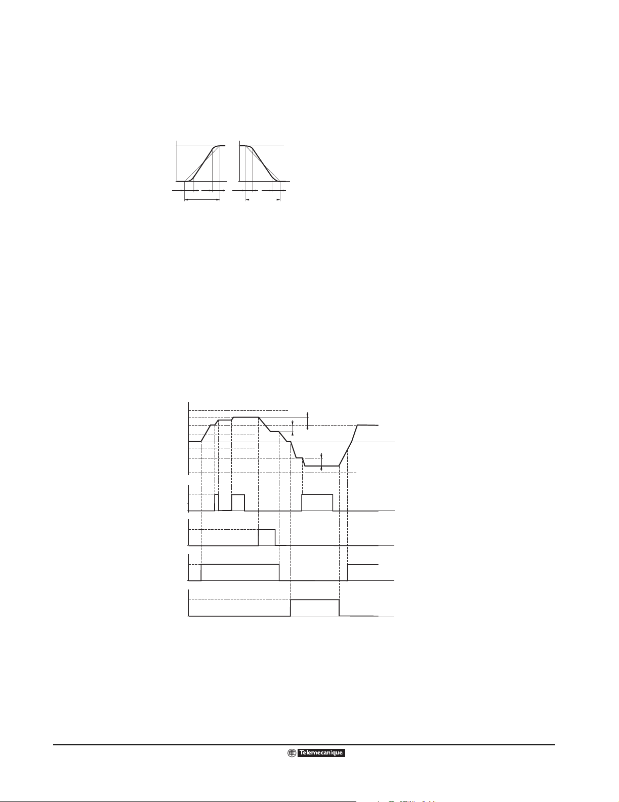
Altivar
®
58 TRX AC Drives
Type FVC Adjustment Parameters
ATV58 TYPE FVC ADJUSTMENT PARAMETERS
Ability to Shape Acceleration and Deceleration Ramps
f (Hz)
0
tA1
tA2 tA3 tA4
ACC or AC2
f (Hz)
tA1: can be set between 0 and 100%
(of ACC or AC2)
tA2: can be set between 0 and (100%
custom ramps copy.eps
- tA1) (of ACC or AC2)
0
t
dEC or dE2
tA3: can be set between 0 and 100%
t
(of dEC or dE2)
tA4: can be set between 0 and (100%
- tA3) (of dEC or dE2)
Parameters tA1, tA2, tA3 and tA4 can
be set in the ADJUST menu
+ Speed/ - Speed Around a Reference:
• When the run command is giv en, t he motor will reach the s peed ref erence fol low ing the accel eration
ramp.
• A pulse on + speed or - speed will change the motor speed. The motor will change speed following
AC2 or DE2.
• If the Speed ref erenc e is chang ed, the ratio b etween the sp eed ref erenc e and th e speed adjuste d by
+ speed or - speed will be constant. This ratio is limited by the parameter (SRP).
• Adjustments around the setpoint using + speed and - speed are made following the AC2 and dE2
ramps.
F : Motor frequency
HSP
Reference
LSP
LSP
Reference
HSP
LI faster
LI slower
LI forward
LI reverse
SRP
SRP
0
SRP
1
0
1t
0
1
0
1
0
+speed-speed.eps
t
t
t
t
t
+ Speed/ - Speed with Single Action Pushbuttons and No Reference Saving: Str = SRE
09/2003
© 2000–2003 Schneider Electric All Rights Reserved
69
Page 70

Altivar
®
58 TRX AC Drives
Type FVC Adjustment Parameters
Speed Loop Modes
Two speed loop modes are available for fine tuning drive controller performance. IP mode is used for
applications in which speed overshoot is not an acceptable response to a change in speed reference.
In this mode, a fix ed filter in the speed ref e renc e li ne imp ro ves noise immu nity and ste ady sta t e sp eed
regulation. PI mode is used in applications that require the fastest response to a change in speed
reference and/or cha nge in motor loadin g.
IP loop: - not possible to exceed reference level
- response time longer than for
the PI loop
Speed
speed reference
motor speed
speed loop modes copy.eps
0
PI loop: - response time very short
- possible to exceed reference level
Speed
0
t
speed reference
motor speed
t
Motor Fluxing Options
Motor fluxing ca n impr ove accelerati on res pons e tim e b y e stab lishi ng m agnetic flux in the m otor be f ore
it receives a run command. There are three motor fluxing options:
• Continuous mode : flux is estab li shed a nd ma intain ed in th e moto r as lon g as p ow er is a pplied to the
drive controller.
• Motor fluxing b y logic input: A logic input is assigned to t he motor fluxin g function. When the assigned
logic input goes high, flux builds in the motor.
• Normal operation: if the lo gic input is not activ e when a run command is gi ve n or if no logic i nput has
been assigned to the function, flux builds in the motor when it starts up. This is the factory setting.
The flux current is equal to 1.5 tim es conf igu red nom ina l mo tor cu rren t unti l ful l flu x is esta blished; it is
then adjusted to the motor no-load current.
Motor fluxing options can be selected in open or closed loop control modes.
Control Mode
This function is used to select open loop or closed loop operation.
70
© 2000–2003 Schneider Electric All Rights Reserved
09/2003
Page 71

Altivar
®
58 TRX AC Drives
Type FVC Adjustment Parameters
PID Regulator
This function is used to regu late a proce ss with a reference and a feedback g iv en by a s ensor. A speed
input gives an initial (or pre dictive) se tpoint fo r start-up. In PID re gulator mode th e ramps are line ar, e ve n
if they are configured diff erently. PID Regulator mod e is activ e if an AI input is assigned to PID Feed back.
Predictive
speed input
PSr
Multiplier
PID
setpoint
PID
feedback
Integral shunting
PrG
Multiplier
PSP PAH
Low-pass filter
ACC
dEC
Linear ramp
++
+Ð
rEO
Offset
PAL
Min / max
alarm
PID
regulator
RPG
RIG
RdG
Error alarm
PEr
Ramp
command
X
AC2
dE2
Run
PLr
PLb
Deadband
f (speed)
PIC
X±1
PID
reversal
+
Auto
Man
PID diagram.eps
+
Reference
Manual setpoint
Auto / man
ACC
dEC
Ramp
PID Regulator parameters:
• Speed Input: digital setpoint via communication link; analog input AI3.
• PID Setpoint: digital setpoint via communication link; 2 or 4 setpoints preset via logic input; analog
Input AI1 (± AI2 ± AI3).
• PID Feedback: analog input AI2 or AI3.
• Manual Setpoint (speed regulation mode): analog input AI3.
• Integral shunting: logic input LI: integral shunted if LIx=1.
• Auto/manual:
— Logic input LI for switc hing operat ion to speed reg ulation (man) if LIx = 1, or PID regulati on (auto)
if LIx = 0.
In automatic mode the following actions are possible:
— Adapt the setpoint input to the process feedback: GAIN (PrG) and OFFSET (rEO).
— Correct PID inversion.
— Adjust the proportional, integral, and derivative gain (RPG, RIG and RdG).
— Use the “alarm” on logic output if a threshold is exceeded (Max. feedback, Min. feedback, and
PID error).
— Assign an analog output for the PID setpoint, PID feedback, and PID error.
— Limit the action of the PID according to the speed, with an adjustable base and ratio:
Speed
09/2003
Deadband
— Apply a ramp to establish the action of the PID on starting (AC2) and stopping (dE2).
— The motor speed is limited between LSP and HSP and is displayed as a percentage.
© 2000–2003 Schneider Electric All Rights Reserved
71
Page 72

Altivar
®
58 TRX AC Drives
Type FVC Analog Inputs
Preset Setpoints for PID Regulator:
2 or 4 preset setpoints require the use of 1 or 2 logic inputs respectively:
LIx Reference LIy LIx Reference
0 Analog reference 0 0 Analog reference
1 Process max 0 1 PI2 (adjustable)
ATV58 TYPE FVC ANALOG INPUTS
Analog Torque Limit:
This function is f or l oad comp ensation , torque o r tra ction correc tion appl ications . It i s av ai labl e only wi th
an I/O extensi on card wi th analog inp ut AI3. The signal appl ied at AI3 oper ates in a l inear f ashion on t he
internal torque limit (parameter TLI in the Drive menu):
If AI3 = 0 V: limit TLI x 0 = 0; If AI3 = 10 V: limit TLI.
Encoder Input Application Function with I/O Extension Card And Encoder Input:
This function pro v ide s spe ed reference summ in g. T he setpoint from the encoder input is summ ed w i th
AI1 (see documentation supplied with the card). Applications include:
• Synchronization of the speed of a number of drive controllers. Parameter PLS on the DRIVE menu
is used to adjust the speed ratio of one motor in relation to that of another.
2 Preset Setpoints 4 Preset Setpoints
Assign: LIx to Pr2 Assign: LIx to Pr2, then LIy to Pr4
1 0 PI3 (adjustable)
1 1 Process max
• Setpoint via encoder.
Encoder Input Application Function with Control Card:
This function prov ides close d loop flux v ector co ntrol with sen sor (inputs A, A-, B, B-). This relates to t he
encoder connected to th e con trol ca rd. It is used for fine speed adjust ments , irres pecti v e of th e state of
the load, and f or c ontrol optim ization (flux v ecto r co ntrol mod e in close d loo p: Ct r = cl osed l oop, DRIVE
menu).
Consistency between the motor frequency and the speed feedback is monitored in the drive controller
fault manag ement system. If there is no enc oder signal (FVC m ode) or if the mo tor frequency an d speed
feedbac k are not co nsist ent, the driv e co ntrolle r giv es a sp eed feedback f au lt and loc k s with code SPF.
During operation, if the diff erence between the motor freq uency and the spe ed feedb ack is grea ter than
5 Hz, the drive controller gives a speed feedback fault and locks with code SPF. If the speed feedback
is greater than 1.2 x maximum frequency, the drive controller gives an overspeed fault with code SOF.
72
© 2000–2003 Schneider Electric All Rights Reserved
09/2003
Page 73

Altivar
®
58 TRX AC Drives
Type FVC Analog and Logic Outputs
ATV58 TYPE FVC ANALOG OUTPUTS
Signed Ramp (Code ORS)
When configured for signed ramp, the analog output provides a signal proportional to the drive
controller’s internal frequency ramp. This output is scaled to indicate rotation direction. AOL
corresponds to the maximum frequency (parameter tFr) in the reverse direction. AOH corresponds to
the maximum freque ncy (parameter tF r) in the f orward direc tion. (AOH + A OL) divided by 2 correspon ds
to zero frequency.
PID Setpoint (Code OPS)
The image of the PID regulato r setpoin t. A OL co rrespon ds to the m inimum setpoi nt. A OH corres ponds
to the maximum setpoint.
PID Feedback (Code OPF)
The image of the PID regulator feedback. AOL corresponds to the minimum feedback. AOH
corresponds to the maximum feedback.
PID Error (Code OPE)
The image of the PID regulator error as a percentage of the sensor range (maximum feedback minus
minimum feedback). AOL correspond to -5%. AOH corresponds to +5%. (AOH plus AOL) divided by 2
corresponds to zero.
PID Integral (Code OPI)
The image of the PID regulator error integral. AOL corresponds to LSP. AOH corresponds to HSP.
ATV58 TYPE FVC LOGIC OUTPUTS
The programmable relay, R2, on the drive controller or the programmable logic output, LO, on an I/O
extension card can be configured for the following additional functions:
PID Error (Code PEE)
Can be assigned to R2 or LO. The logic output is active (state 1) or the relay is energized if the PID
regulator output error is greater than the threshold set by parameter PEr.
PID Feedback Alarm (Code PFA)
Can be assigned to R2 or LO. The logic output is active (state 1) if the PID feedback moves outside the
range set by parameters PAH and PAL.
09/2003
© 2000–2003 Schneider Electric All Rights Reserved
73
Page 74
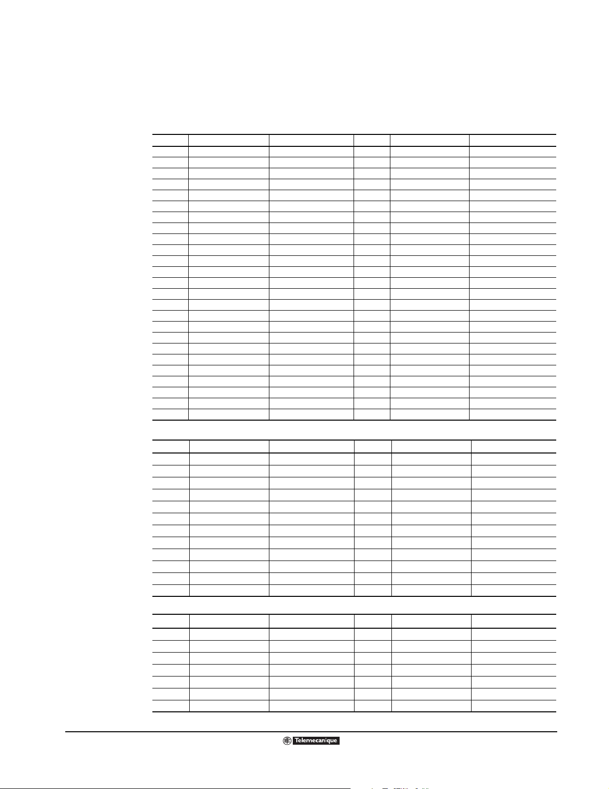
Altivar
®
58 TRX AC Drives
Parameter Summary
PARAMETER SUMMARY
The following tables show the ATV58 TRX Type H configuration parameters. This page can be copied
and used as a worksheet to customize settings for your application.
Adjustment Parameters
Code Fact. Setting Cust. Setting Code Fact. Setting Cust. Setting
ACb no SP6 30 Hz Hz
ACC 3 s s SP7 35 Hz Hz
dEc 3 s s JOG 10 Hz Hz
LSP 0 Hz Hz JGt 0.5 s s
HSP 50 / 60 Hz Hz brL 0 Hz Hz
FLG 20% % Ibr 0 A A
StA 20% % brt 0 s s
ItH 0.9 of I
IdC 0.7 ItH A bEt 0 s s
tdC 0.5 s s FFt 50/60 Hz Hz
SdC Varies A rPG 1
JPF 0 Hz Hz rIG 1 / s / s
JF2 0 Hz Hz PSP 0.0 s s
JF3 0 Hz Hz FbS 0.1
AC2 5 s s PIC no
dE2 5 s s PI2 30% %
tLS no no or s PI3 60% %
USC 1 dtd 105% %
UFr 100% % dtS 1
SLP 100% % Ctd 1.36 of I
PFL 20% % ttd 100% %
SP2 10 Hz Hz tL2 200% %
SP3 15 Hz Hz Ftd 50/60 Hz Hz
SP4 20 Hz Hz F2d 50/60 Hz Hz
SP5 25 Hz Hz
n
A bEn 0 Hz Hz
n
A
Drive Menu Parameters
Code Factory Setting Customer Setting Code Factory Setting Customer Setting
UnS depends on catalog number V Stt STN
FrS 50 / 60 Hz Hz dCF 4
nCr 0.9 of I
nSP depends on catalog number rpm CLI 1.3 6 of I
COS depends on catalog number AdC yes
tUn no PCC 1
tFr 60 / 72 Hz Hz SFt LF
nLd no SFr depends on catalog number kHz
Fdb no nrd yes
Frt 0 Hz Hz SPC no
rPt LIN PGt DET
brA no PLS 1024
n
A tLI 200% %
n
Command Menu Pa rameters
Code Factor y Settin g Customer Setting Code Factory Setti n g Customer Setting
tCC 2 W AOH 20 mA mA
tCt LEL Str no
rln no LCC no
bSP no PSt yes
CrL 4 mA mA Add 0
CrH 20 mA mA tbr 19200
AOL 0 mA mA rPr no
74
© 2000–2003 Schneider Electric All Rights Reserved
09/2003
Page 75

Altivar
®
58 TRX AC Drives
Parameter Summary
Fault Menu Parame ters
Code Fact. Setting Cust. Setting Code Fact. Setting Cust. Setting
Atr no LFL no
nAr 5 LFF 0
tAr 30.0 s FLr no
rSt RSP StP no
OPL yes Sdd no
IPL yes EPL no
tHt ACL
I/O Assignment
Analog
Logic
Inputs
LI1 AI1 r1
LI2 AI2 r2
LI3 AO1
LI4
LI5 AI3 AO
LI6 LO
Customer Setting
Analog
Inputs
Customer Setting
Outputs
and Logic
Outputs
Customer Setting
NOTE: Shaded rows indicate I/O available on extension cards.
09/2003
© 2000–2003 Schneider Electric All Rights Reserved
75
Page 76

Altivar
®
58 TRX AC Drives
Menu Overview
MENU OVERVIEW
Menu 1 – DISPLAY Menu
Parameter Code
Drive State
Steady State
Accelerating
Decelerating
Current Limit
I
n
DC Injection Braking
Freewheel Stop
Braking with Ramp Mod
Frequency Reference
LCU
Frequency Reference
Output Frequency
Motor Speed
Motor Current
Machine Speed
Output Power
Mains Voltage
Motor Thermal
Drive Thermal
Last Fault
Consumption (wH)
Run Time (Hours)
Menu 2 – ADJUST Menu
Parameter Code Factory Setting
Frequency Reference
LCU
Inv. Phases
Acceleration -s
Deceleration -s
Accelerate 2 -s
Decelerate 2 -s
Low Speed -Hz
High Speed -Hz
Gain -%
Stability -%
Thermal Current -A
DC Injection Time -s
DC Injection Curr -A
Cont. DC Injection Curr -A
Jump Freq. -Hz
Jump Freq. 2 -Hz
Jump Freq. 3 -Hz
LSP Time -s
Machine Speed Coeff.
IR Compensation -%
Slip Comp. -%
Preset Sp.2 -Hz
Preset Sp.3 -Hz
Preset Sp.4 -Hz
Preset Sp.5 -Hz
Preset Sp.6 -Hz
Preset Sp.7 -Hz
Frequency Lev.Att -H z
Frequency Lev2.Att -Hz
Torque Limit 2 -%
Current Level Att. -A
Brake Release Lev -Hz
Brake Release I -A
Brake ReleaseTime -s
Brake Engage Lev -Hz
Brake EngageTime -s
Trip Threshold NST -Hz
Tachometer Coeff. *
Jog Freq. -Hz
Jog Delay -s
V/f Profile -%
Thermal Level Att. -%
Pl Prop. Gain
Pl Int. Gain -/s
PI Filter
Pl Coeff
Pl Inversion
PI Preset 2 %
PI Preset 3 %
ATV th. fault
* Requires addition of I/O option card
VW3A58201U (analog) or VW3A58202U (digital)
rdY
rUn
ACC
dEc
CLI
dCb
nSt
Obr
LFr
LCU
FrH
rFr
SPd
LCr
USP
OPr
ULn
tHr
tHd
LFt
APH
rtH
LFr
LCU
ACb
ACC
dEC
AC2
dE2
LSP
HSP
FLG
StA
ItH
tdC
IdC
SdC
JPF
JF2
JF3
tLS
USC
UFr
SLP
SP2
SP3
SP4
SP5
SP6
SP7
Ftd
F2d
tL2
Ctd
brL
Ibr
brt
bEn
bEt
FFt
dtS
JOG
JGt
PFL
ttd
rPG
rIG
PSP
FbS
PIC
PI2
PI3
dtd
0.00
no
3 s
3 s
5 s
5 s
0 Hz
50 / 60 Hz
20%
20%
0.9 In
0.5 s
0.7 ItH
Varies
0 Hz
0 Hz
0 Hz
no
1
100%
100%
10 Hz
15 Hz
20 Hz
25 Hz
30 Hz
35 Hz
50 / 60 Hz
200%
1.36 of I
0 Hz
0 A
0 s
0 Hz
0 s
1
10 Hz
0.5 s
20%
100%
1
1/s
0.0
0.1
no
30%
60%
105%
n
Menu 3 – DRIVE Menu
Parameter Code Factory Setting
Nom. Motor Volt -V
Nom. Motor Freq. -Hz
Nom. Motor Curr -A
Nom. Motor Speed -rpm
Motor CosPhi (power fact.)
Auto Tuning
Max. Frequency -Hz
Energy Economy
I Limit Adapt.
Dec Ramp Adapt
Switch Ramp 2 -Hz
Type of Stop
Standard Stop
Fast Stop
Freewheel
DC Injection
Ramp Type
Linear Ramp
S Ramp
U Ramp
Dec Ramp Coef.
Torque Limit -%
Int. I Limit -%
Auto DC Inj.
Mot. Power Coef.
Switching Freq. Type
Range of 0.5 to 4 kHz
Range of 4 to 16 kHz
High Duty Cycle w/ derat.
Sw. Freq 0.5 to16 -kHz
Noise Reduction
Special Motor
no
yes
PSM (small motor)
PG (feedback sensor)Type *
Incremental Encoder
Detector (pulse or edge)
Num. Pulses *
UnS
FrS
nCr
nSP
CoS
tUn
tFr
nLd
Fdb
brA
Frt
Stt
Stn
FSt
nSt
DCI
rPt
LIn
S
U
dCF
tLI
CLI
AdC
PCC
SFT
LF
HF1
HF2
SFr
nrd
SPC
PGt
InC
dEt
PLS
depends on cat. #
50 / 60 Hz
0.9 of I
n
depends on cat. #
depends on cat. #
no
60 / 72 Hz
no
no
no
0 Hz
Stn
LIn
4
200 %
1.36 of I
n
yes
1
LF
depends on cat. #
depends on cat. #
depends on cat. #
0.5 to 16 kHz
yes
no
dEt
1
Menu 4 – CONTROL Menu
Parameter Code Factory Setting
Terminal Strip Con
Two Wire 2W
Three Wire 3W
Type 2 Wire
No Transition
Low to High Trans.
Forward Input Pri.
Inhibit Reverse
Low Speed Magmt
Linear LSP to HSP
Pedestal Start
Deadband Start
AI2 Min. Ref. -mA
AI2 Max. Ref. -mA
Min. Val. AO mA
Max. Val. AO mA
Reference Memory
No memory
Run Com. removed
Power removed
Keypad Com.
Stop Priority
Drive Address
Bd Rate RS-485
Reset Counters
tCC
2 W
3 W
tCt
LEL
TRN
PFo
rIn
bSP
no
BLS
BNS
CrL
CrH
AOL
AOH
Str
no
RAM
EEP
LCC
PSt
Add
tbr
rpr
2 W
LEL
no
no
4 mA
20 mA
0 mA
20 mA
no
no
yes
0
These diagrams include all parameters that may appear
in the designated menu. The parameters actually visible
on your d rive cont roller de pends on its config uration a nd
the options installed.
76
© 2000–2003 Schneider Electric All Rights Reserved
09/2003
Page 77

Altivar
®
58 TRX AC Drives
Menu Overview
Menu 5– I/O Menu
Parameter Code Factory Setting
LI2 Assign
LI3 Assign
LI4 Assign
LI5 Assign *
LI6 Assign *
Not assigned
RV: Reverse
Switch Ramp2
JOG
+SP: +Speed
-Speed
2 preset Sp
4 preset Sp
8 preset Sp
Freewheel Stop
DC inject
Fast stop
Multi. Motor
TorqueLim2
Forced Local
Fault Reset
Auto/manu
Auto-tune
PI Auto/Man
PI 2 Preset
PI 4 Preset
External flt
Torque Limit by AI
AI2 Assign
AI3 Assign *
Not assigned
Speed ref 2
Summed ref.
PI regulator
PI Manual Ref.*
Tacho feedback *
Therm. Sensor *
Torque Limit *
Encoder feedback *
R2 Assign / LO assign
Not assigned
Drive running
Output contactor
Freq reference attain.
HSP attained
Current level attained
Reference Freq. Attain.
Motor thermal lvl (Attain)
Brake logic
4-20mA loss
F2 attained
ATV th. alarm
AO1 Assign
AO Assign
Not assigned
Motor current
Motor frequency
Output ramp
Motor torque
Signed Torque
Signed Ramp
PI Reference
PI Feedback
PI Error
PI Integral
Motor Power
Motor Thermal
Drive Thermal
LI2
LI3
LI4
LI5
LI6
no
RV
RP2
JOG
SP
-SP
PS2
PS4
PS8
NST
OCI
FSt
CHP
TL2
FLO
rSt
RFC
Atn
PAU
Pr2
Pr4
EDD
tLA
AI2
AI3
no
Fr2
SAI
PIF
PIM
SFb
PtC
AtL
RGI
r2 / LO
no
rUn
OCC
FtA
FLA
CtA
SrA
tSA
bLC
APL
F2A
TAD
AO1
AO
no
OCr
OFr
OrP
trq
Stq
OrS
OPS
OPF
OPE
OPI
OPr
tHr
tHd
Menu 6 – FAULT Menu
Parameter Code Fac tory Setting
Auto Restart
Nb Max Reset
Reset Pause
Reset Type
Partial Reset
Total Reset
Output Phase Loss
Input Phase Loss
Thermal Protection
No motor protection
Self Cooled motor
Force Cooled motor
Loss Follower
Immediate Fault
Restart on Signal Return
Stop and Fault
Run at Preset Speed
Run at last speed
Catch On Fly
Controlled Stop
Phase loss drive trip
Maintain DC Bus
Follow Ramp
Ramp not Followed *
External Fault
Atr
nAr
tAr
rSt
rSP
rSG
OPL
IPL
tHt
no
ACL
FCL
LFL
yes
Stt
LSF
LFF
RLS
FLr
StP
no
MMS
FRP
Sdd
EPL
no
5
30.0 s
RSP
yes
yes
ACL
no
no
no
no
yes
Menu 7 – FILES Menu
Parameter Code Factory Setting
File 1 State
File 2 State
File 3 State
File 4 State
Operation Type
No Operation Req.
Save Configuration
Transfer File to Drive
Return to Factory Set
Password
F1S
F2S
F3S
F4S
FOt
no
StR
REC
Ini
Cod
FREE
FREE
FREE
FREE
no
0000
LANGUAGE Menu
Parameter Code
English
Francais
Deutsch
Espanol
Italiano
LNG
LNG
LNG
LNG
LNG
MACRO-CONFIG Menu
Parameter Code
Hdg: Material Handling
GEn: General Use
VT: Variable Torque
CUS: Customize
CFG
CFG
CFG
CFG
09/2003
* Requires addition of I/O option card VW3A58201U
(analog) or VW3A58202U (digital)
© 2000–2003 Schneider Electric All Rights Reserved
77
Page 78

Altivar
®
58 TRX AC Drives
Communication Parameters
NOTE: Refer to
bulletin
VVDED397058US for
specific address
numbers and more
information.
COMMUNICATION PARAMETERS
(PARAMETERS AVAILABLE VIA THE COMMUNICATION LINK)
The communication link identifies ATV58 TRX drive contr ollers as a series of holding registers. The
tables in this section describe the content of the registers to show what information is available. The
registers are grouped by the following functions and are in numerical order:
• General configur ation registers.
• Drive configuration registers.
• I/O configuration registers.
• Fault con figuration registers .
• Adjustment registers.
• Control registers.
• Display registers.
• Special DRIVECOM registers.
General Configuration Registers
Word Code Units Description Possible Values or Range
W1
or 16#5FE0/1
W3
or 16#5FE0/3
W4
or 16#5FE0/4
W5
or 16#5FE0/5
W6
or 16#5FE0/6
W7
or 16#5FE0/7
W8
or 16#5FE0/8
W9
or 16#5FE0/9
W10
or 16#5FE0/A
W11
or 16#5FE0/B
W12
or 16#5FE0/C
W13
or 16#5FE0/D
W14
or 16#5FE0/E
W15
or 16#5FE0/F
CIC — Incorrect configuration
Upon power up, read CIC:
If CIC = 0: normal
If CIC ≠ 0: malfunction
Write CIC to 0 to return to factory settings.
CFG — Macro-configuration.
CRL 0.1 mA Minimum reference of input AI2 0–200 (0 to 20.0 mA)
CRH 0.1 mA Maximum reference of input AI2 40–200 (4.0 to 20.0 mA)
TCC — 2-wire/3-wire control via terminals. Mo dificati on of
TCT — Type of 2-wire control 0 = LEL: Level detection (0 or 1)
PST — STOP key has priority
STR — Speed reference storage
ADD — Drive address via the standard RS-485 serial link. 0 to 31
ORT — Drive power overrating for variable torque
RIN — Inhibits operation of the motor in the reverse
BSP — Manage low speed operation as a function of the
AOL 0.1 mA Minimum reference of analog output AO and AO1 0 to 200 (0 to 20.0 mA)
AOH 0.1 mA Maximum refe rence of analog output AO and AO1 0 to 200 (0 to 20.0 mA)
Modification of this parameter reassigns other
parameters.
this parameter will reassign the I/O.
(regardless of assigned control mode—i.e.,
terminal strip, keypad, or serial link)
(+/–Speed)
applications
Modifying this parameter returns the following
parameters to the factory settings: UNS, NCR,
NSP, COS, TUN, ITH and IDC.
This parameter can be m odi fied o n ATV58 Type H
controllers when the macro-configuration (CFG,
W3) is set to variable torque (VT). See instruction
bulletin VVDED397047US (latest revision) for a
complete description. For ATV58 Type FVC
models, this parameter is always at 0.
direction (by logic input, analog input, serial
command, or REV key on the keypad display)
analog reference
Bit 0 = 0: Normal rating
Bit 0 = 1: Drive controller rating modified
Bit 1 = 0: Option card detection normal
Bit 1 = 1: Type of option card modified
Bit 2 = 0: Option card detection normal
Bit 2 = 1: Option card removed
Bit 3 = 0: Contents of EEPROM correct
Bit 3 = 1: Contents of EEPROM incorrect
Bits 4 to 15: Reserved
0 = HDG: Material handling
1 = GEN: General use
2 = VT: Variable torque (except Type FVC)
0 = 2W: 2-wire control
1 = 3W: 3-wire control
1 = TRN: Transitio n detection
(switching from 0 to 1 or 1 to 0)
2 = PFO: Transition detection with priority given to forward
over reverse
0 = No
1 = Yes
0 = NO: Reference not saved
1 = RAM: Reference saved in RAM
2 = EEP: Reference saved in EEPROM
3 = SRE: Reference adju stmen t ra nge li mited b y par ame t er
SRP (Type FVC only)
0 = Broadcasting without response
0 = No (high overtorque)
1 = Yes (standard overtorque)
0 = No
1 = Yes
0 = No: Normal
1 = BLS: Peak limiting (deadband)
2 = BNS: Base limiting (pedestal)
78
© 2000–2003 Schneider Electric All Rights Reserved
09/2003
Page 79

Altivar
®
58 TRX AC Drives
Communication Parameters
General Configuration Registers (Continued)
Word Code Units Description Possible Values or Range
W16
or 16#5FE0/10
W17
or 16#5FE0/11
Drive Configuration Registers
Word Code Units Description Possible Values or Range
W50
or 16#5FE1/1
W51
or 16#5FE1/2
W52
or 16#5FE1/3
W53
or 16#5FE1/4
W54
or 16#5FE1/5
W55
or 16#5FE1/6
W56
or 16#5FE1/7
W57
or 16#5FE1/8
W58
or 16#5FE1/9
W59
or 16#5FE1/A
W60
or 16#5FE1/B
[1]
W61
or 16#5FE1/C
W62
or 16#5FE1/D
W63
or 16#5FE1/E
W64
or 16#5FE1/F
W65
or 16#5FE1/10
W66
or 16#5FE1/11
W67
or 16#5FE1/12
W68
or 16#5FE1/13
[1]
W69
or 16#5FE1/14
[1] This parameter does not exist for ATV58 Type FVC drive controllers.
TBR — Communication speed through the RS-485 port 7 = 9600 baud
RPR — Reset kWh or total running time 0 = No
SFT — Switching frequency range.
SFR — PWM switching frequency
TFR 0.1 Hz Maximum output frequency If SFR = 0.5 kHz: 10.0 to 62.0
FRS 0.1 Hz Nominal motor frequency 100–5000 (10.0 to 500.0 Hz)
NCR 0.1 A Nominal motor current 0.25 INV to 1.36 INV
UNS 1 V Nominal motor voltage ATV58•••M2: 200 to 240
NSP 1 rpm Nominal motor speed 0 to 32767
COS 0.01 Motor cosine Phi (power factor) 0.50 to 1.00
TLI 1% Torque limit 0 to 200
TUN — Auto-tune of motor 0 = No: auto-tune not performed
NRD — Motor noise reduction by switching frequency
NLD — Energy saving function
RPT — Type of acceleration and deceleration ramps 0 = LIN: Linear
DCF 1 Deceleration reduction coefficient used with Fast
BRA — Deceleration ramp adaptation 0 = No
FRT 0.1 Hz Ramp switching threshold (switch to AC2 and DE2
BER — Reserved
ADC — Automatic DC injection on stop; or, for Type FVC
PLS 1 Number of pulses per encoder revolution (For
PCC 0.1 Motor power load coefficient (in th e e ven t of mot or
Adjusting this parameter changes the following
parameters to the factory setting:
SFR (W51)•NCR (W54)
NRD (W60)•CLI (W72)
ITH (W258)•IDC (W270)
IBR (W277)•CTD (W282)
(Values 5 and 6 are not on all drive ratings)
modulation
(VT macro only)
Stop: DEC ÷ DCF = Fast Stop ramp
if output frequency > FRT and FRT ≠ 0)
only, if CTR = FVC, zero speed is maintained
encoder feedback
I/O card)
switching)
8 = 19200 baud
1 = APH: Reset to 0 the kWh
2 = RTH: Reset to 0 the total running time
0 =LF: Low frequency
1 =HF1: High frequency without derating.
If th ≥ 95%, switch to 4 kHz.
If th < 70%, return to SFR frequency.
2 =HF2: High frequency with derating by one rating
0 = 0.5 kHz if SFT = LF
1 = 1 kHz if SFT = LF
2 = 2 kHz if SFT = LF
3 = 4 kHz if SFT = LF
4 = 8 kHz if SFT = HF1 or HF2
5 = 12 kHz if SFT = HF1 or HF2
6 = 16 kHz if SFT = HF1 or HF2
If SFR = 1 kHz: 10.0 to 125.0
If SFR = 2 kHz: 10.0 to 250.0
If SFR = 4 kHz: 10.0 to 500.0
If SFR = 8 kHz: 10.0 to 500.0
If SFR = 12 kHz: 10.0 to 500.0
If SFR = 16 kHz: 10.0 to 500.0
(INV = drive controller nominal current)
ATV58•••N4: 200 to 500
ATV58F•••N4: 200 to 500
(value from internal table used).
If written to 0: return to value from table
1 = Yes: auto-tune command
2 = Done: auto-tune performed
0 = No
1 = Yes
0 = No
1 = Yes
1 = S: S-shaped
2 = U: U-shaped
3 = CUS: Customized (Type FVC only)
1 to 10
1 = Yes
0 to HSP
0 = No
1 = Yes
1 to 1024
2 to 10 (0.2 to 1.0)
09/2003
© 2000–2003 Schneider Electric All Rights Reserved
79
Page 80

Altivar
®
58 TRX AC Drives
Communication Parameters
Drive Configuration Registers (Continued)
Word Code Units Description Possible Values or Range
[1]
W70
or 16#5FE1/15
W71
or 16#5FE1/16
W72
or 16#5FE1/17
[1]
W73
or 16#5FE1/18
W74
or 16#5FE1/19
W75
or 16#5FE1/1A
W76
or 16#5FE1/1B
W77
or 16#5FE1/1C
W78
or 16#5FE1/1D
W79
or 16#5FE1/1E
[1] This parameter does not exist for ATV58 Type FVC drive controllers.
SPC — Special motor 0 = No
PGT — Type of motor shaft speed sensor (Indicates the
CLI 0.1 A Internal current limit 0.1 to 1.36 x INV
FDB — Current limit adaptation based on output
FLU — Motor fluxing 0 = FNC: Non-continuous fluxing
CTR — Control mode selection 0 = SVC: Open loop
PGI 1 Number of pulses per encoder revolution (control
SSL — Type of speed loop selection 0 = IP: IP structure
ENC — Check encoder feedback
STT — Type of stop. The type of stop assigned by this
number of signals wired to the en coder f eedbac k I /
O card)
frequency (VT macro only)
card)
Do not write values 0 or 2.
Do not write value 1 if W78 = 2.
parameter is carried out until the motor frequ ency
drops below the setting of paramet er FFT (W313 ),
after which the motor freewheel stops.
1 = Yes
2 = PSM: Use f or v ery small mo tors or fo r open circuit output
voltage testing.
0 = INC: Incremental encoder. A, A–, B, B–, are hard-wired
1 = DET: Detector. Only A is hard-wired
(INV = drive controller nominal current)
0 = No
1 = Yes
1 = FCT: Continuous fluxing
1 = FVC: Closed loop
100 to 5000
1 = PI: PI structure
0 = No: test not performed
1 = Yes: perform the test
2 = Done: test performed
0 = STN: Normal ramp stop
1 = FST: Fast stop
2 = NST: Freewheel stop
3 = DCI: DC injection stop
I/O Configuration Registers
Wor d Code Description Possible Values or Range
W100
or
16#5FE2/1
W101
or
16#5FE2/2
W102
or
16#5FE2/3
W103
or
16#5FE2/4
[1]
LI1 Assignment of
logic input LI1
LI2 Assignment of
logic input LI2
LI3 Assignment of
logic input LI3
LI4 Assignment of
logic input LI4
1 = STP: Stop (if TCC = 3W)
2 = FW: Forward operation (if TCC = 2W)
0 = NO: Not assigned
2 = FW: Forward operation (if TCC = 3W)
3 = RV: Reverse operation
4 = RP2: Ramp switching
5 = JOG: Jog operation
6 = +SP: +Speed
7 = –SP: –Speed
8 = PS2: 2 preset speeds
9 = PS4: 4 preset speeds
10 = PS8: 8 preset speeds
11 = RFC: Reference switching
12 = NST: Freewheel stop
13 = DCI: DC injection stop
0 = NO: Not assigned
3 = RV: Reverse operation
4 = RP2: Ramp switching
5 = JOG: Jog operation
6 = +SP: +Speed
7 = –SP: –Speed
8 = PS2: 2 preset speeds
9 = PS4: 4 preset speeds
10 = PS8: 8 preset speeds
11 = RFC: Reference switching
12 = NST: Freewheel stop
13 = DCI: DC injection stop
14 = FST: Fast stop
0 = NO: Not assigned
3 = RV: Reverse operation
4 = RP2: Ramp switching
5 = JOG: Jog operation
6 = +SP: +Speed
7 = –SP: –Speed
8 = PS2: 2 preset speeds
9 = PS4: 4 preset speeds
10 = PS8: 8 preset speeds
11 = RFC: Reference switching
12 = NST: Freewheel stop
13 = DCI: Injection stop
14 = FST: Fast stop
Values specific to ATV58 Type FVC models
14 = FST: Fast stop
15 = CHP: Motor switching; or open
loop/closed loop switching
16 = TL2: Second torque limit
17 = FLO: Force to local
18 = RST: Clear faults
19 = ATN: Auto tune
20 = SPM: Save reference
21 = FLI: Motor fluxing
22 = PAU: PID auto-man
23 = PIS: PID integral shunting
24 = PR2: 2 preset PID references
26 = TLA: Torque limit by AI
27 = EDD: External fault
15 = CHP: Motor switching; or open loop/
closed loop switching
16 = TL2: Second torque limit
17 = FLO: Force to local
18 = RST: Clear faults
19 = ATN: Auto tune
20 = SPM: Save reference
21 = FLI: Motor fluxing
22 = PAU: PID auto-man
23 = PIS: PID integral shunting
24 = PR2: 2 preset PID references
25 = PR4: 4 preset PID references
26 = TLA: Torque limit by AI
27 = EDD: External fault
15 = CHP: Motor switching; or open loop/
closed loop switching if CTR = FVC
16 = TL2: Second torque limit
17 = FLO: Forced local mode
18 = RST: Fault reset
19 = ATN: Auto tune
20 = SPM: Save reference
21 = FLI: Motor fluxing
22 = PAU: PID auto-man
23 = PIS: PID integral shunting
24 = PR2: 2 preset PID references
25 = PR4: 4 preset PID references
26 = TLA: Torque limit by AI
27 = EDD: External fault
[1]
[1]
[1]
[1]
[1]
[1]
[1]
[1]
[1]
[1]
[1]
[1]
80
© 2000–2003 Schneider Electric All Rights Reserved
09/2003
Page 81

I/O Configuration Registers (Continued)
Word Code Description Possible Values or Range
W104
or
16#5FE2/5
W105
or
16#5FE2/6
W107
or
16#5FE2/8
W108
or
16#5FE2/9
W110
or
16#5FE2/B
W111
or
16#5FE2/C
W112
or
16#5FE2/D
[1]
LI5 Assignment of
logic input LI5
LI6 Assignment of
logic input LI6
AI2 Assignment of
analog input AI2
AI3 Assignment of
analog input AI3
or of encoder
input
(according to
type of I/O card)
R2 Assignment of
relay R2
LO Assignment of
logic output LO
AO Assignment of
analog output
AO
0 = NO: Not assigned
3 = RV: Reverse operation
4 = RP2: Ramp switching
5 = JOG: Jog operation
6 = +SP: +Speed
7 = –SP: –Speed
8 = PS2: 2 preset speeds
9 = PS4: 4 preset speeds
10 = PS8: 8 preset speeds
11 = RFC: Reference switching
12 = NST: Freewheel stop
13 = DCI: Injection stop
14 = FST: Fast stop
0 = NO: Not assigned
2 = FR2: Speed reference 2
3 = SAI: Summing reference
0 = NO: Not assigned
2 = FR2 = Speed reference 2 (125–500 hp only)
3 = SAI: Summing reference
4 = PIF: PI feedback (PI control)
5 = SFB: Tachogenerator feedback
6 = RGI: Encoder feedback (except Type FVC models)
7 = PTC: PTC probes
8 = ATL: Analog torque limit
9 = DAI: Subtracting reference
10 = PIM: manual speed reference of the PID regulator (auto-man)
11 = FPI: speed reference of the PID regulator (predictive reference)
0 = NO: Not assigned
2 = RUN: Drive running
3 = OCC: Downstream contactor control
4 = FTA: Frequency threshold (FTD) reached
5 = FLA: High speed reached
6 = CTA: Current threshold (CTD) reached
7 = SRA: Frequency reference reached
8 = TSA: Thermal threshold (TTD) reached
9 = BLC: Brake sequence
10 = PEE: PID error
11 = PFA: PID feedback alarm
12 = APL: Loss of 4–20 mA follower signal
13 = F2A: 2nd frequency threshold (F2D) reached
14 = TAD: Drive thermal state threshold reached
0 = NO: Not assigned
2 = RUN: Drive running
3 = OCC: Downstream contactor control
4 = FTA: Frequency threshold (FTD) reached
5 = FLA: High speed reached
6 = CTA: Current threshold (CTD) reached
7 = SRA: Frequency reference reached
8 = TSA: Thermal threshold (TTD) reached
10 = PEE: PID error
11 = PFA: PID feedback alarm
12 = APL: Loss of 4–20 mA follower signal
13 = F2A: 2nd frequency threshold (F2D) reached
14 = TAD: Drive thermal state threshold reached
0 = NO: Not assigned
1 = OCR: Motor current
2 = OFR: Motor speed
3 = ORP: Ramp output
4 = TRQ: Motor torque
5 = STQ: Signed motor torque
6 = ORS: Signed ramp output
Values specific to ATV58 Type FVC models
[1]
[1]
Altivar
®
58 TRX AC Drives
Communication Parameters
15 = CHP: Motor switching; or open loop/
closed loop switching if CTR= FVC
16 = TL2: Second torque limit
17 = FLO: Forced local mode
18 = RST: Fault reset
19 = ATN: Auto tune
20 = SPM: Save reference
21 = FLI: Motor fluxing
22 = PAU: PID auto-man
23 = PIS: PID integral shunting
24 = PR2: 2 preset PID references
25 = PR4: 4 preset PID references
26 = TLA: Torque limit by AI
27 = EDD: External fault
4 = PIF: PI feedback (PI control)
8 = ATL: Analog torque limit
9 = DAI: Subtracting reference
[1]
[1]
[1]
7 = OPS: PID reference
8 = OPF: PID feedback
9 = OPE: PID error
10 = OPI: PID integral
11 = OPR: Motor power output
12 = THR: Motor thermal state
13 = THD: Drive thermal state
[1]
[1]
[1]
[1]
[1]
[1]
[1]
[1]
[1]
[1]
[1]
09/2003
© 2000–2003 Schneider Electric All Rights Reserved
81
Page 82

Altivar
®
58 TRX AC Drives
Communication Parameters
I/O Configuration Registers (Continued)
Wor d Code Description Possible Values or Range
W113
or
16#5FE2/E
[1]
Values specific to ATV58 Type FVC models
Fault Configuration Registers
Word Code Description Possible Values or Range
W150
or 16#5FE3/1
W151
or 16#5FE3/2
W152
or 16#5FE3/3
W153
or 16#5FE3/4
W154
or 16#5FE3/5
W155
or 16#5FE3/6
W156
or 16#5FE3/7
W157
or 16#5FE3/8
W158
or 16#5FE3/9
W159
or 16#5FE3/A
W160
or 16#5FE3/B
W161
or 16#5FE3/C
AO1 Assignment of
analog output
AO1
(Only on ATV58
Type FVC drive
controllers)
ATR — Automatic restart
OPL — Motor phase loss
IPL — Input phase loss
THT — Motor thermal protection
LFL — Loss of follower
FLR — Catch a spinning load
STP — Controlled stop on loss of input power
SDD — Ramp not followed
RST — Type of reset
LFF 0.1 Hz Default speed if 4–20 mA follower signal is lost.
EPL Response to external fault input issued by logic
input
ACB Electronic output phase inversion 0 = No
0 = NO: Not assigned
1 = OCR: Motor current
2 = OFR: Motor speed
3 = ORP: Ramp output
4 = TRQ: Motor torque
5 = STQ: Signed motor torque
6 = ORS: Signed ramp output
7 = OPS: PID reference
8 = OPF: PID feedback
9 = OPE: PID error
10 = OPI: PID integral
11 = OPR: Motor power output
12 = THR: Motor thermal state
13 = THD: Drive thermal state
1 = Yes: Immediate fault
3 = LSF: Stop followed by fault indiction
1 = Yes
Adjustment Registers
Word Code Units Description Possible Values or Range
W250
or 16#5FE5/1
W251
or 16#5FE5/2
W252
or 16#5FE5/3
W253
or 16#5FE5/4
W254
or 16#5FE5/5
W255
or 16#5FE5/6
[1]
W256
or 16#5FE5/7
W257
or 16#5FE5/8
W258
or 16#5FE5/9
W259
or 16#5FE5/A
W260
or 16#5FE5/B
W261
or 16#5FE5/C
[1]
This parameter does not exist for ATV58 Type FVC drive controllers.
HSP 0.1 Hz High speed LSP to TFR
LSP 0.1 Hz Low speed 0 to HSP
ACC 0.1 s
DEC 0.1 s
UFR 1% IR compensation
FLG 1% Frequency loop gain 0 to 100
PFL 1% V/F ratio profile 0 to 100 if CFG = VT
STA 1% Frequency loop stability 0 to 100
ITH 0.1 A Current setting for motor thermal protection 0.25 to 1.36
SLP 1% Slip compensation 0 if CFG = VT
AC2 0.1 s
DE2 0.1 s
Acceleration
or
(time between 0 and FRS)
0.01 s
Deceleration
or
(time between FRS and 0)
0.01 s
(adjustment of auto-tune value)
Acceleration 2
or
(time between 0 and FRS)
0.01 s
Deceleration 2
or
(time between FRS and 0)
0.01 s
0: ramp of 0.05 s (special case)
1 to 9999: ramp of 0.1 s to 999.9 s or
0.01 to 99.99. See INR (W291) for Type FVC.
0: ramp of 0.05 s (special case)
1 to 9999: ramp of 0.1 s to 999.9 s or
0.01 to 99.99. See INR (W291) for Type FVC.
0 to 150 if SPC = No
0 to 800 if SPC = Yes
0 if CFG = VT
100 if CFG = HDG or GEN
x INV (drive controller nominal current)
0 to 150 if CFG = HDG or GEN
0: ramp of 0.05 s (special case)
1 to 9999: ramp of 0.1 s to 999.9 s or
0.01 to 99.99. See INR (W291) for Type FVC.
0: ramp of 0.05 s (special case)
1 to 9999: ramp of 0.1 s to 999.9 s or
0.01 to 99.99. See INR (W291) for Type FVC.
82
© 2000–2003 Schneider Electric All Rights Reserved
09/2003
Page 83

Altivar
®
58 TRX AC Drives
Communication Parameters
Adjustment Registers (Continu ed)
Word Code Units Description Possible Values or Range
W262
or 16#5FE5/D
W263
or 16#5FE5/E
W264
or 16#5FE5/F
W265
or 16#5FE5/10
W266
or 16#5FE5/11
W267
or 16#5FE5/12
W268
or 16#5FE5/13
W269
or 16#5FE5/14
W270
or
16#5FE5/15
W271
or 16#5FE5/16
W272
or 16#5FE5/17
[1]
W273
or 16#5FE5/18
W274
or 16#5FE5/19
W275
or 16#5FE5/1A
W276
or 16#5FE5/1B
W277
or 16#5FE5/1C
W278
or 16#5FE5/1D
W279
or 16#5FE5/1E
W280
or 16#5FE5/1F
[1]
W281
or 16#5FE5/20
W282
or 16#5FE5/21
W283
or 16#5FE5/22
W284
or 16#5FE5/23
W285
or 16#5FE5/24
W286
or 16#5FE5/25
W287
or 16#5FE5/26
W288
16#5FE5/27
W289
or 16#5FE5/28
W290
or 16#5FE5/29
W291
or 16#5FE5/2A
W292
or 16#5FE5/2B
W293
or 16#5FE5/2C
[1]
This parameter does not exist for ATV58 Type FVC drive controllers.
JOG 0.1 Hz Jog frequency 0 to 100 (0.0 to 10.0 Hz)
JGT 0.1 s Delay between two consecutive jog operations 0 to 20 (0.0 to 2.0 s)
SP2 0.1 Hz Preset speed 2 LSP to HSP
SP3 0.1 Hz Preset speed 3 LSP to HSP
SP4 0.1 Hz Preset speed 4 LSP to HSP
SP5 0.1 Hz Preset speed 5 LSP to HSP
SP6 0.1 Hz Preset speed 6 LSP to HSP
SP7 0.1 Hz Preset speed 7 LSP to HSP
IDC 0.1 A DC injection current level 0.1 to 1.36
TDC 0.1 s DC injection time (in the case of automatic DC
TLS 0.1 s Low speed (LSP) dwell timer 0 = No: no limit
BRL 0.1 Hz Mechanical brake release threshold 0 to 100 (0.0 to 10.0 Hz)
BEN 0.1 Hz Mechanical brake engage threshold
BRT 0.01 s Mechanical brake release time 0 to 500 (0.00 to 5.00 s)
BET 0.01 s Mechanical brake engage time 0 to 500 (0.00 to 5.00 s)
IBR 0.1 A Mechanical brake release current threshold 0 to 1.36
TL2 1% Second torque limit 0 to 200
RPG 0.01 PI proportional gain 1 to 10000 (0.01 to 100.00)
RIG 0.01/s PI integral gain 1 to 10000 (0.01 to 100.00)
FBS 0.1 PI feedback scale factor 10 to 1000 (1.0 to 100.0)
CTD 0.1 A Motor current threshold for signalling 0.25 to 1.36 x INV
TTD 1% Thermal threshold for signalling 0 to 118
FTD 0.1 Hz Frequency threshold for signalling LSP to HSP
DTS 0.01 Tachogenerator feedback scaling (For I/O card
JPF 0.1 Hz Skip frequency
PIC — Inverts the PI feedback signal 0 = No (normal)
SDC 0.1 A Continuous DC injection braking current level on
USC 0.01 Machine coefficient. Applied to RFR for custom
BIP — Brake release pulse 0 = No: Pulse in the direction requested
INR — Fine increment in the ramp setting s for A CC, DE C,
SRP 1% Range of action around the reference for +/–
TA1 1% Rounding of the start of the acceleration ramp 0 to 100% of ramp time
injection at stop)
Type FVC: Zero speed holding time with CTR =
closed loop
Type FVC: Not significant if
CTR = closed loop
with analog input)
(frequency range: ±2.5Hz)
stopping after 30 s. See TDC (W271)
display of machine speed under Display parame ter
USP (USP = RFR x USC).
AC2, and DE2
speed function
x INV (drive controller nominal current)
0 to 300 = 0.0 s to 30.0 s
301 = CONT: continuous injection
1 to 9999 = time of 0.1 s to 999.9 s
0 to LSP
x INV (drive controller nominal current)
(INV = drive controller nominal current)
100 to 200 (1.00 to 2.00)
0 to HSP
1 = Yes (inverted)
Min: 0.1 x INV
Max: 1.36 x INV
(INV = drive controller nominal current)
1 to 10000 (0.01 to 100.00)
1 = Yes: Always pulse in the ascending direction
0 = 0.1 s
1 = 0.01 s
0 to 50% of the reference
09/2003
© 2000–2003 Schneider Electric All Rights Reserved
83
Page 84

Altivar
®
58 TRX AC Drives
Communication Parameters
Adjustment Registers (Continued)
Word Code Units Description Possible Values or Range
W294
or 16#5FE5/2D
W295
or 16#5FE5/2E
W296
or 16#5FE5/2F
W297
or 16#5FE5/30
W298
or 16#5FE5/31
W299
or 16#5FE5/32
W300
or 16#5FE5/33
W301
or 16#5FE5/34
W302
or 16#5FE5/35
W303
or 16#5FE5/36
W304
or 16#5FE5/37
W305
or 16#5FE5/38
W306
or 16#5FE5/39
W307
or 16#5FE5/3A
W308
or 16#5FE5/3B
W309
or 16#5FE5/3C
W310
or 16#5FE5/3D
W311
or 16#5FE5/3E
W312
or 16#5FE5/3F
W313
or 16#5FE5/40
W314
or 16#5FE5/41
W315
or 16#5FE5/42
W316
or 16#5FE5/43
W317
or 16#5FE5/44
W318
or 16#5FE5/45
[1]
This parameter does not exist for ATV58 Type FVC drive controllers.
TA2 1% Rounding of the end of the acceleration ramp 0 to (100% of ramp time – TA1)
TA3 1% Rounding of the start of the deceleration ramp 0 to 100% of ramp time
TA4 1% Rounding of the end of the deceleration ramp 0 to (100% of ramp time – TA3)
SPG 1% PI type speed loop proportional gain 0 to 1000
SIG 1% PI type speed loop integral gain 0 to 1000
REO — PID regulator reference offset –999 to +999
PAL 1% PID feedback alarm min. threshold 0 to 100%
PAH 1% PID feedback alarm max. threshold 0 to 100%
PER 1% PID error alarm max. threshold 0 to 100%
RDG 0.01 PID regulator derivative gain 0 to 10000 (0 to 100.00)
PSP 0.1 s PID feedback filter time constant 0 to 100 (0 to 10.0)
PSR 1% PID speed input multiplier ratio 0 to 100
PLR 1% PID regulator deadband ratio 0 to 100
PLB 0.1 Hz PID regulator deadband threshold 0 to HSP
PI2 1% 2nd preset PID reference 0 to 100
PI3 1% 3rd preset PID reference 0 to 100
PRG — PID regulator reference gain –999 to +999
JF2 0.1 Hz Skip frequency 2
JF3 0.1 Hz Skip frequency 3
FFT 0.1 Hz Frequency threshold for start of freewheel stop
F2D 0.1 Hz Second frequency threshold for signalling LSP to HSP
DTD 1% Drive thermal state threshold value 0–118%
SP8 0.1 Hz Preset speed 8 (125–500 hp only) LSP to HSP
NAR 1 Number of restart attempts 0–255
TAR s Time between auto restarts 0.1–999.9
± 2.5 Hz around setpoint
± 2.5 Hz around setpoint
during deceleration phase if STT (W79) = STN or
FST
0 to HSP
0 to HSP
0 to HSP
84
© 2000–2003 Schneider Electric All Rights Reserved
09/2003
Page 85
Altivar
®
58 TRX AC Drives
Communication Parameters
Control Registers
Word Code Units Description Possible Values or Range
W400
or 16#5FE7/1
W401
or 16#5FE7/2
W402
or 16#5FE7/3
W403
or 16#5FE7/4
[1]
Parameter is reinitialized at the end of time-out unless bit 14 (NTO) of CMI (W402 or 16#5FE7/3) is set to 1.
[2]
The EEPROM life limit is 100,000 write operations.
CMD — Command word
LFR 0.1 Hz
CMI — Internal control register (application program).
PISP 0.001 PI setpoint in serial link mode.
Serial link frequency reference.
or
Signed in two’s complement.
0.015
If bit 9 of CMI is 0, the resolution of LFR is 0.1 Hz (0–5000 = 0.0 to 500.0 Hz).
Hz
If bit 9 is 1, the resolution of LFR becomes approximately 0.015 Hz per count
(0–32767 = 0 to 500 Hz).
ATV58 Type FVC only.
PISP is used only if an analog input is assigned to PIF: PID feedback. When using PISP, LFR (frequency
reference) and LFRD (speed reference) have no effect on the motor speed. The analog input for PID feedback
remains active in the serial link mode.
[1]
Bit 0 = 0 and Bit 15 = 0: Not ready
[1]
LSP to HSP
[1]
Bit 0 = 1 and Bit 15 = 0: Ready
Bit 1 = 0: Return to “Switch On disabled” status
Bit 1 = 1: No action
Bit 2 = 0 and Bit 15 = 0: E-stop (rapid deceleration)
Bit 2 = 1: No action
Bit 3 = 0 and Bit 15 = 0: DRIVECOM stop command
Bit 3 = 1 and Bit 15 = 0: DRIVECOM run command
Bits 4 to 6: Reserved
Bit 7 = 0: No action
Bit 7 = 1: Reset faults
Bit 8 = 0 and Bit 15 = 1: Activate control via serial link
Bit 8 = 1 and Bit 15 = 1: Deactivate control via serial link
Bits 9 and 10: Reserved
Bit 11 = 0: Normal direction command
Bit 11 = 1: Reverse direction command
Bit 12 = 0: Motor run command (RUN)
Bit 12 = 1: Motor stop command
Bit 13 = 0: No action
Bit 13 = 1: Stop by DC injection command
Bit 14 = 0: No action
Bit 14 = 1: Fast stop command
Bit 15 = 0: DRIVECOM control register
Bit 15 = 1: Non-DRIVECOM control register
[1]
Bit0 = 0: No action
Bit0 = 1: Recall factory settings command. This bit
automatically resets to 0 after accepting the request; but if
CMI is a periodic variable, the PLC program must write it to
0 after the first request has been accepted.
Bit1 = 0: No action
Bit1 = 1: Save configuration/adjustments in EEPROM if
voltage is sufficient (no USF fault present). This bit
automatically resets to 0 after accepting the request; but if
CMI is a periodic variable, the PLC program must write it to
0 after the first request has been accepted.
Bit2 = 0: No action
Bit2 = 1: Recall configuration/adjustm ents in E EPROM. This
bit automatically resets to 0 after accepting the request; but
if CMI is a periodic variable, the PLC program must write it to
0 after the first request has b een accepted. This bit is inactive
if the motor is running.
Bit3 = 0: No action
Bit3 = 1: External fault command (EPF)
Bit4 = 0: No action
Bit4 = 1: Ramp switching command
Bit5 = 0: No action
Bit5 = 1: Motor switching command; or
Open loop/closed loop switching (Type FVC only)
Bit6 = 0: No action
Bit6 = 1: Second torque limit command
Bit7: Leave this bit at 0
Bit8 = 0: Normal speed loop ramps (Type FVC only)
Bit8 = 1: Short-circuiting of speed loop ramps (Type FVC
only)
Bit9 = 0: Resolution of keypad o r serial l ink spe ed re f er ence
(LFR) is 0.1 Hz
Bit9 = 1: Resolution of keypad o r serial l ink spe ed re f er ence
(LFR) is approximately 0.015 Hz
Bits 10 to 11: Reserved
Bit12: Reserved
Bit13 = 0: Drive controller not locked at stop
Bit13 = 1: Drive controller locked at stop
Bit14 (NTO) = 0: Control with communication check
Bit14 (NTO) = 1: Control without communication check
Bit15 = 0: Parameter consistency check
Bit15 = 1: No parameter consistency chec k, drive contro ll er
locked at stop. Switching this bit to 0 revalidates all
parameters.
0 to 10,000
[2]
[2]
09/2003
© 2000–2003 Schneider Electric All Rights Reserved
85
Page 86

Altivar
®
58 TRX AC Drives
Communication Parameters
Monitoring Registers
Wor d Co de Description Possible Valu es or Range
W450
or 16#5FE8/1
W451
or 16#5FE8/2
W452
or 16#5FE8/3
W453
or 16#FE8/4
W454
or 16#5FE8/5
W455
or 16#5FE8/6
W456
or 16#5FE8/7
W457
or 16#5FE8/8
W458
or 16#5FE8/9
FRH Frequency reference (absolute value) Value read
RFR Output frequency applied to the motor (absolute
value)
SPD Motor speed estimated by the drive controller
(absolute value)
LCR Motor current Value read
ULN Line voltage Value read
THR Motor thermal state
(100% = Nominal thermal state, 118% = OLF
threshold)
THD Drive controller thermal state (100% = Nominal
thermal state, 118% = OHF threshold)
LFT Last fault 0 = NOF: No fault saved
ETA Drive controller DRIVECOM status word Bit 0 = 0: Power not ready
Units of 0.1 Hz
Value read
Units of 0.1 Hz or
0.015 Hz
Value read
Units of 1 rpm
Units of 0.1 A
Units of 0.1 V
Value read
Units of 1%
Value read
Units of 1%
1 = INF: Internal fault
2 = EEF: EEPROM memory fault
3 = CFF: Configuration parameters incorrect (on initialization)
4 = CFI: Configuration parameters invalid (if writing a configuration)
5 = SLF: Standard communication link fault (link break)
6 = ILF: Fast communication link fault (link break)
7 = CNF: Fast communication network fault
8 = EPF: External fault
9 = OCF: Overcurrent fault (prolonged ICL)
10 = CRF: P recharge relay fault
11 = SPF: Loss of speed feedback fault
12 = ANF: Ramp not followed fault
13 = LFF: Loss of follower fault (4–20 mA)
14 = TSF: Thermal sensor fault
15 = OTF: Motor overheating fault (thermal sensor)
16 = OHF: Drive controller overheating fault (on heatsink)
17 = OLF: Motor overload fault ( thermal simulati on or thermal se nsor)
18 = OBF: DC bus overvoltage fault
19 = OSF: Input supply overvoltage fault
20 = OPF: Motor phase loss fault
21 = PHF: Input supply phase loss fault (> 1 s)
22 = USF: Input supply undervoltage fault (> 200 ms)
23 = SCF: Motor short circuit fault (motor phase or ground fault)
24 = SOF: Overspeed fault (with speed feedback:
1.11 x HSP; without feedback: 1.2 x TFR)
Bit 0 = 1: Power ready for startup
Bit 1 = 0: Drive controller not ready
Bit 1 = 1: Drive controller ready (RDY)
Bit 2 = 0: DRIVECOM stop
Bit 2 = 1: DRIVECOM run
Bit 3 = 0: No fault
Bit 3 = 1: Fault present (FAI)
Bit 4 = 0: Power present
Bit 4 = 1: Power not present
Bit 5 = 0: E-stop (rapid deceleration) in progress
Bit 5 = 1: No E-stop
Bit 6 = 0: Status ≠ Switching Disabled
Bit 6 = 1: Status = Switching Disabled (freewheel stop)
Bit 7 = 0: Alarm absent
Bit 7 = 1: Alarm present
Bit 8: Reserved
Bit 9 = 0: Forced local active (FLO)
Bit 9 = 1: Forced local inactive
Bit 10 = 0: Speed reference not reached (transient state)
Bit 10 = 1: Speed reference reached (steady state)
Bit 11 = 0: LFRD reference (in rpm) normal (W603 or 16#6042)
Bit 11 = 1: LFRD reference (in rpm) exceeded (> HSP or < LSP)
Bits 12 and 13: Reserved
Bit 14 = 0: No stop from keypad display STOP key
Bit 14 = 1: Stop from keypad display STOP key
Bit 15 = 0: Forward direction of rotation (output frequency)
Bit 15 = 1: Reverse direction of rotation (output frequency)
86
© 2000–2003 Schneider Electric All Rights Reserved
09/2003
Page 87

Altivar
Communication Parameters
Monitoring Registers (Continu ed)
Wor d Code Description Possible Values or Range
W459
or 16#5FE8/A
W460
or 16#5FE8/B
W461
or 16#5FE8/C
ETI Drive controller internal status register no. 1 Bit 0 = 0: Write parameters authorized
ETI2 Drive controller internal status register no. 2 Bit 0 = 0: Drive controller not in factory autotest mode
ETI3 Drive controller internal status register no. 3 Bit 0 = 0: Drive controller power does no t exceed 7.5 kW @ 230 V or 15
Bit 0 = 1: Write parameters not authorized
(EEPROM saving in progress)
Bit 1 = 0: No parameter consistency check,
drive controller locked at stop
Bit 1 = 1: Parameter consistency check
Bit 2 = 0: Fault reset not authorized
Bit 2 = 1: Fault reset authorized
Bit 3 = 0: No motor fluxing in progress (Type FVC only)
Bit 3 = 1: Motor fluxing in progress (Type FVC only)
Bit 4 = 0: Motor stopped
Bit 4 = 1: Motor running
Bit 5 = 0: No DC injection
Bit 5 = 1: DC injection
Bit 6 = 0: Drive controller running in steady state
Bit 6 = 1: Drive controller running in transient state (ACC or DEC)
Bit 7 = 0: No thermal overload alarm
Bit 7 = 1: Thermal overload alarm
Bit 8 = 0: No alarm if excessive braking
Bit 8 = 1: Alarm if excessive braking
Bit 9 = 0: Drive controller not accelerating
Bit 9 = 1: Drive controller accelerating
Bit 10 = 0: Drive controller not decelerating
Bit 10 = 1: Drive controller decelerating
Bit 11 = 0: No current limit alarm
Bit 11 = 1: Current limit alarm
Bit 12: Reserved
Bit 14 = 0, Bit 13 = 0: Control via wired terminal strip
Bit 14 = 0, Bit 13 = 1: Control via keypad display
Bit 14 = 1, Bit 13 = 0: Control via standard serial link
Bit 14 = 1, Bit 13 = 1: Control via fast serial link
Bit 15 = 0: Forward direction of rotation requested (reference)
Bit 15 = 1: Reverse direction of rotation requested (reference)
Bit 0 = 1: Drive controller in factory autotest mode
Bit 1 = 0: Drive controller not in board test mode
Bit 1 = 1: Drive controller in board test mode
Bit 2 = 0: Drive controller not in product test mode
Bit 2 = 1: Drive controller in product test mode (burn-in)
Bit 3 = 0: High speed not reached
Bit 3 = 1: High speed reached
Bit 4 = 0: Speed reference not reached
Bit 4 = 1: Speed reference reached
Bit 5 = 0: Frequency threshold (FTD) not reached
Bit 5 = 1: Frequency threshold (FTD) reached
Bit 6 = 0: Current threshold (CTD) not reached
Bit 6 = 1: Current threshold (CTD) reached
Bit 7 = 0: PID feedback correct (Type FVC only)
Bit 7 = 1: PID feedback exceeded (Type FVC only)
Bit 8 = 0: PID error correct (Type FVC only)
Bit 8= 1: PID error exceeded (Type FVC only)
Bit 9 = 0: 4–20 mA signal OK
Bit 9 = 1: Loss of 4–20 mA signal
Bit 10 = 0: No drive thermal alarm
Bit 10 = 1: Drive thermal alarm
Bits 11 to 15: Reserved
kW @ 400 V
Bit 0 = 1: Drive controller power exceeds 7.5 kW @ 230 V and 15 kW
@ 400 V
Bit 1 = 0: Drive controller po wer doe s not e xceed 30 kW @ 400 V or 15
kW @ 230 V)
Bit 1 = 1: Drive controller power e xceeds 30 kW @ 400 V and 15kW @
230 V
Bit 2 = 0: ATV58 Type H model
Bit 2 = 1: ATV58 Type FVC model
Bit 3 = 0: Overrating not allowed for lower power range model
Bit 3 = 1: Overrating allowed for lower power range model
(50/60 Hz switch on 60 Hz, caliber 3 kW @ 460 V to 15 kW @ 460V,
and CFG = VT)
Bit 4 = 0: No extended VT ratings
Bit 4 = 1: Extended VT ratings
(ETI3 bit 3 = 1 and ORT = 1)
®
58 TRX AC Drives
09/2003
© 2000–2003 Schneider Electric All Rights Reserved
87
Page 88
Altivar
®
58 TRX AC Drives
Communication Parameters
Monitoring Registers (Continued)
Wor d Co de Description Possible Valu es or Range
W462
or 16#5FE8/D
W463
or 16#5FE8/E
W464
or 16#5FE8/F
W465
or 16#5FE8/10
W466
or 16#5FE8/11
W467
or 16#5FE8/12
W468
or 16#5FE8/13
W469
or 16#5FE8/14
W470
or 16#5FE8/15
W471
or 16#5FE8/16
W472
or 16#5FE8/17
W473
or 16#5FE8/18
W474
or 16#5FE8/19
W475
or 16#5FE8/1A
DP1 Past fault no. 1 0 = NOF: No fault saved
EP1 Status during past fault no. 1 Bit 0 = 0: Drive controller not ready
DP2 Past fault no. 2 Same format as DP1 (W462 or 16#5FE8/13)
EP2 Status during past fault no. 2 Same format as EP1 (W463 or 16#5FE8/14)
DP3 Past fault no. 3 Same format as DP1 (W462 or 16#5FE8/13)
EP3 Status during past fault no. 3 Same format as EP1 (W463 or 16#5FE8/14)
DP4 Past fault no. 4 Same format as DP1 (W462 or 16#5FE8/13)
EP4 Status during past fault no. 4 Same format as EP1 (W463 or 16#5FE8/14)
DP5 Past fault no. 5 Same format as DP1 (W462 or 16#5FE8/13)
EP5 Status during past fault no. 5 Same format as EP1 (W463 or 16#5FE8/14)
DP6 Past fault no. 6 Same format as DP1 (W462 or 16#5FE8/13)
EP6 Status during past fault no. 6 Same format as EP1 (W463 or 16#5FE8/14)
DP7 Past fault no. 7 Same format as DP1 (W462 or 16#5FE8/13)
EP7 Status during past fault no. 7 Same format as EP1 (W463 or 16#5FE8/14)
1 = INF: Internal fault
2 = EEF: EEPROM memory fault
3 = CFF: Configuration parameters incorrect (initialization)
4 = CFI: Configuration parameters invalid (if writing a configuration)
5 = SLF: Standard communication link fault (link break)
6 = ILF: Fast communication link fault (link break)
7 = CNF: Fast communication network fault
8 = EPF: External fault
9 = OCF: Overcurrent fault (prolonged ICL)
10 = CRF: P recharge relay fault
11 = SPF: Loss of speed feedback fault
12 = ANF: Ramp not followed fault
13 = LFF: Loss of follower fault (4–20 mA)
14 = TSF: Thermal sensor fault
15 = OTF: Motor overheating fault (thermal sensor)
16 = OHF: Drive controller overheating fault (on heatsink)
17 = OLF: Motor overload fault ( thermal simulati on or thermal se nsor)
18 = OBF: DC bus overvoltage fault
19 = OSF: Input supply overvoltage fault
20 = OPF: Motor phase loss fault
21 = PHF: Input supply phase loss fault (> 1 s)
22 = USF: Input supply undervoltage fault (> 200 ms)
23 = SCF: Motor short circuit fault (phase to earth)
24 = SOF: Overspeed fa ult (w ith spee d f ee dback: 1.11 x HSP; without
feedback: 1.2 x TFR)
Bit 0 = 1: Drive controller ready (RDY)
Bit 1 = 0: E-stop (rapid deceleration) in progress
Bit 1 = 1: E-stop (rapid deceleration) not in progress
Bit 2 = 0: Status ≠ Switching Disabled
Bit 2 = 1: Status = Switching Disabled (freewheel stop)
Bit 3 = 0: Forced local active (FLO)
Bit 3 = 1: Forced local inactive
Bit 4 = 0: Forward rotation (output frequency)
Bit 4 = 1: Reverse rotation (output frequency)
Bit 5 = 0: Motor stopped
Bit 5 = 1: Motor running
Bit 6 = 0: No DC injection
Bit 6 = 1: DC injection
Bit 7 = 0: No therm al overload alarm
Bit 7 = 1: Thermal overload alarm
Bit 8 = 0: No excessive braking alarm
Bit 8 = 1: Excessive braking alarm
Bit 9 = 0: Drive controller not accelerating
Bit 9 = 1: Drive controller accelerating
Bit 10 = 0: Drive controller not decelerating
Bit 10 = 1: Drive controller decelerating
Bit 11 = 0: No current limit alarm
Bit 11 = 1: Current limit alarm
Bit 12: Reserved
Bit 14 = 0, Bit 13 = 0: Control via wired terminal strip
Bit 14 = 0, Bit 13 = 1: Control via keypad display
Bit 14 = 1, Bit 13 = 0: Control via standard serial link
Bit 14 = 1, Bit 13 = 1: Control via fast serial link
Bit 15 = 0: Forward direction of rotation requested (reference)
Bit 15 = 1: Reverse direction of rotation requested (reference)
88
© 2000–2003 Schneider Electric All Rights Reserved
09/2003
Page 89

Altivar
Communication Parameters
Monitoring Registers (Continu ed)
Wor d Code Description Possible Values or Range
W476
or 16#5FE8/1B
W477
or 16#5FE8/1C
Monitoring Registers (Continu ed)
Word Code Units Description Possible Values or Range
W478
or 16#5FE8/1D
W479
or 16#5FE8/1E
W480
or 16#5FE8/1F
W481
or 16#5FE8/20
W482
or 16#5FE8/21
W483
or 16#5FE8/22
W48
or 16#5FE8/23
W485
or 16#5FE8/24
W486
or 16#5FE8/25
W487
or 16#5FE8/26
W488
or 16#5FE8/27
DP8 Past fault no. 8 Same format as DP1 (W462 or 16#5FE8/13)
EP8 Status during past fault no. 8 Same format as EP1 (W463 or 16#5FE8/14)
IOLR — State of logic I/O Bit 0 = State of logic input LI1 (active at 1)
AI1R 0.001 V State of analog input AI1 (actual
AI2R 0.002 mA State of analog input AI2 (actual
AI3R 0.001 V
or
1
AOR 0.002 mA Image of analog output AO Write authorized if AO = No (not assigned) and option car d is other th an
DF1 — Register of active faults no. 1
DF2 — Register of active faults no. 2 (no
PPN — Number of motor pole pairs Value read
CUS — I/O reassigned
OTR 1%
or
0.1%
FRO 0.1 Hz Ramp output (signed) Value read
size calibrated and scaled)
size calibrated and scaled)
Voltage of analog input AI3 or
number of pulses on encoder
input, depending on type of
I/O card
(no fault if bits = 0)
Used only in manufacturing test.
Do not use.
fault if bits = 0)
Used only in manufacturing test.
Do not use.
(Macro-configuration = CUS)
Motor torque Value read
Bit 1 = State of logic input LI2 (active at 1)
Bit 2 = State of logic input LI3 (active at 1)
Bit 3 = State of logic input LI4 (active at 1)
Bit 4 = State of logic input LI5 (active at 1)
Bit 5 = State of logic input LI6 (active at 1)
Bits 6 and 7: Reserved
Bit 8 = State of relay R1 (active at 1)
Bit 9 = State of relay R2 (active at 1)
Write authorized if R2 = No (not assigned)
Bit 10 = State of logic output LO (active at 1)
Write authorized if LO = No (not assigned)
Bit 11 = State of red fault LED (active at 1)
Bit 12 = State of precharge relay (active at 1)
Bit 13 = State of dynamic brake transistor (active at 1)
Bits 14 and 15: Reserved
Value read
Value read
0 to 10000 = 0 to 20 mA
–10000 to +10000 (for VW3A58201U option card)
or
–32768 to 32767 (for VW3A58202U option card)
analog or digital I/O option
0 to 10000 = 0 to 20 mA
Read only if assigned: Value read
Bit 0 = 1: Incorrect calibration constants (INF)
Bit 1 = 1: Unknown drive controller rating (INF)
Bit 2 = 1: Unknown or incompatible option (INF)
Bit 3 = 1: HD (ASIC) initialization incorrect (INF)
Bit 4 = 1: EEPROM control board fault (EEF)
Bit 5 = 1: EEPROM power board fault (EEF)
Bit 6 = 1: Incorrect configuration (CFF)
Bit 7 = 1: Invalid configuration (CFI)
Bit 8 = 1: Standard communication link fault (SLF)
Bit 9 = 1: Fast communication link fault (ILF)
Bit 10 = 1: Fast communication network fault (CNF)
Bit 11 = 1: External fault via standard serial link (EPF)
Bit 12 = 1: External fault via fast serial link (EPF)
Bit 13 = 1: Motor short circuit fault (SCF)
Bit 14 = 1: Precharge relay closure too long (CRF)
Bit 15 = 1: Precharge relay command cut-off (CRF)
Bit 0 = 1: Speed feedback loss fault (SPF)
Bit 1 = 1: Overspeed with speed feedback (SOF)
Bit 2 = 1: Ramp not followed with speed feedback (ANF)
Bit 3 = 1: Overcurrent fault (prolonged ICL) (OCF)
Bit 4 = 1: Loss of follower (4–20 mA) fault (LFF)
Bit 5 = 1: Thermal sensor fault (TSF)
Bit 6 = 1: Motor overheating fault (thermal sensor) (OTF)
Bit 7 = 1: Drive controller overheating fault (OHF)
Bit 8 = 1: Motor overload fault (OLF)
Bit 9 = 1: Fast communication time-out fault (CNF)
Bit 10 = 1: DC bus overvoltage fault (OBF)
Bit 11 = 1: Input supply overvoltage fault (OSF)
Bit 12 = 1: Motor phase loss fault (OPF)
Bit 13 = 1: Input supply phase loss fault (PHF)
Bit 14 = 1: Input supply undervoltage fault (USF)
Bit 15 = 1: Control board power supply fault (INF)
0 = No
1 = Yes
100% corresponds to nominal motor torque
®
58 TRX AC Drives
09/2003
© 2000–2003 Schneider Electric All Rights Reserved
89
Page 90

Altivar
®
58 TRX AC Drives
Communication Parameters
Monitoring Registers (Continued)
Word Code Units Description Possible Values or Range
W489
or 16#5FE8/28
W490
or 16#5FE8/29
W491
or 16#5FE8/2A
W492
or 16#5FE8/2B
W493
or 16#5FE8/2C
W494
or 16#5FE8/2D
W495
or 16#5FE8/2E
Special DRIVECOM Registers
Word Code Units Parameter Name and Description Possible Values or Range
W600
or 16#603F
W601
or 16#6040
W602
or 16#6041
W603
or 16#6042
W604
or 16#6043
W605
or 16#6044
W606
or 16#6046/1
W607 SMIH Reserved 0
W608
or 16#6046/2
W609 SMAH — Reserved 0
[1] For ATV58 Type FVC, if CMI Bit 9 = 0, units are in rpm; if CMI Bit 9 = 1, units are in 0.015 Hz.
USPL 0.01 Lower byte of machine speed Value read
USPH 0.01 Upper byte of machine speed Value read
OPR 1% Output power estimated by the
AO1R 0.002 mA Image of analog output AO1. Write authorized if AO1 = No (not assigned):
UOP 0.1 V Voltage applied to the motor.
APH 1 kWh
or
1 MWh
RTH 1 hr Total motor run time Value read
ERRD — ErrorCode
CMDD — Controlword
ETAD — Statusword
LFRD 1 rpm
FRHD 1 rpm SpeedRef
RFRD 1 rpm
SMIL 1 rpm SpdMinMax
SMAL 1 rpm SpdMinMax
[1]
[1]
drive controller
Exists only on Type FVC models.
Drive power meter (kWh) Value read.
Fault code
Read/Write
Command word—same as parameter CMD
Read/Write
Status word—same as parameter ETA
Write prohibited
SpeedSetP
Speed reference in rpm (ref erence not pe ak
limited)
Read/Write
Ramp output (signed) in rpm
Write prohibited
SpeedActV
Motor speed in rpm
Write prohibited
Minimum speed in 32 bits
Equivalent to LSP (W251), but in rpm
Read/Write
Maximum speed in 32 bits
Equivalent to HSP (W250), but in rpm
Read/Write
Value read
100% corresponds to nominal motor power
0 to 10000 (0 to 20 mA)
Read only if assigned: Value read
Value read
If bit 15 = 0, units are kWh as given by bits 0 to 14.
If bit 15 = 1, units are MWh as given by bits 0 to 14.
16#0 = NOF: No fault
16#1000 = CRF: Pre-charge relay fault
or = OLF: Motor overload (calculation or PTC probes)
or = SOF: Overspeed
16#2310 = OCF: Overcurrent (prolonged LIC)
16#2320 = SCF: Motor short-circuit (phase/earth)
16#3110 = OSF: Line supply overvoltage
16#3120 = USF: Line supply undervoltage (> 200 ms)
16#3130 = PHF: Line supply phase loss (> 1s)
16#3310 = OBF: DC bus overvoltage
or = OPF: Motor phase loss
16#4210 = OHF: Drive overheating (heatsink)
16#4310 = OTF: Motor overheating (PTC probes)
16#5520 = EEF: EEPROM memory fault
16#6100 = INF: Internal fault
16#6300 = CFF: Configuration incorrect (on initialization)
or = CFI: Configuration invalid (if writing a configuration)
16#7300 = ANF: Ramp not followed
or = LFF: Loss of 4–20 mA signal
or = TSF: Thermal sensor fault
16#7310 = SPF: Speed feedback missing or miswired
16#7510 = SLF: Serial link fault—keypad port (link break)
16#7520 = ILF: Fast serial link fault—options port (link break)
or = CNF: Fast serial link communication network fault
16#9000 = EPF: External fault
–32768 to 32767
0 to HSP
LSP to TFR
90
© 2000–2003 Schneider Electric All Rights Reserved
09/2003
Page 91

Altivar
Communication Parameters
Special DRIVECOM Registers (Continued)
Word Code Units Parameter Name and Description Possible V alues or Range
W610
or 16#6048/1
W611 SPAH — Reserved 0
W612
or 16#6048/2
W613
or 16#6049/1
W614 SPDH — Reserved 0
W615
or 16#6049/2
SPAL 1 rpm SpdAcc
SPAT 1 s SpdAcc
SPDL 1 rpm SpdDec
SPDT 1 s S pdDec
Acceleration ramp determined by a speed
variation in rpm via words W610 and W611
(32 bits) plus a time variation in seconds
given by wor d W612 (1 6 bits)
Read/Write
Acceleration ramp determined by a speed
variation in rpm via words W610 and W611
(32 bits) plus a time variation in seconds
given by wor d W612 (1 6 bits)
Read/Write
Deceleration ramp determined by a speed
variation in rpm via words W613 and W614
(32 bits) plus a time variation in seconds
given by wor d W615 (1 6 bits)
Read/Write
Deceleration ramp determined by a speed
variation in rpm via words W613 and W614
(32 bits) plus a time variation in seconds
given by wor d W615 (1 6 bits)
Read/Write
1 to 65535
0 to 65535
1 to 65535
0 to 65535
®
58 TRX AC Drives
09/2003
© 2000–2003 Schneider Electric All Rights Reserved
91
Page 92

Altivar
®
58 TRX AC Drives
Power Section Construction Information
POWER SECTION CONSTRUCTION INFORMATION
Block Diagram for ATV58HU09M2 to ATV58HD12M2 (0.5 to 10 hp, 208/230 Vac) and
ATV58HU18N4 to ATV58HD23N4 (1 to 20 hp, 400/460 Vac)
IGBT
Output
Section
T3
T6
T5
Current
Measurement
U
V
W
T2
L1
L2
L3
Diode
Bridge
Section
+
Optional
EMC
Filter
−
Pre-charge
Relay
Capacitor
Bank
Dynamic
Braking
Transistor
DBT
T1
PA
PB
T4
The block diagram above provides an overview of the construction of the ATV58 TRX drive controller
power section. The drive controllers in the horsepower ranges referenced above are built in five frame
sizes. (See t he dim ensio nal dr a win gs on p ages 1 20 to 1 22.) The v arious fr am e siz es s hare in comm on
many components and technological advances:
• In frame size 1, the diode bridge section and the insulated gate bipolar transistor (IGBT) output
section are integrated into one module. The dynamic braking module is purchased and mounted
separately. All other frame sizes have the dynamic brake switching module internal to the product.
• In frame sizes 2 and 3, the diode bridge section, the IGBT output section, and the dynamic braking
components are integrated into one module.
BlkDiag1.eps
• In frame siz es 4 and 5, the diode bridge section is one module . The IGBT output se ction is in tegrated
into a power module (PM). The dynamic braking transistor is incorporated into the diode bridge
section or the power module, depending on the rating.
• The EMC filter is optional on frame sizes 3, 4, and 5.
Integration reduces the part count and the wiring and connection points required to connect
components. The output section has fault detection and short circuit protection of the output transistors
integrated into the module. The use of these modules eliminates individual gate drive cards and
associated wiring as used by most other manufacturers in this horsepower ran ge. These features
combine to make the Altivar 58 TRX drive fit in a smaller package while improving the reliability of the
product.
92
© 2000–2003 Schneider Electric All Rights Reserved
09/2003
Page 93

Altivar
®
58 TRX AC Drives
Power Section Construction Information
Block Diagram ATV58HD16M2 to ATV58HD46M2 (15 to 40 hp/50 hp VT 208/230 Vac) and
ATV58HD28N4 to ATV58HD79N4 (25 to 75 hp/100 hp VT 400/460 Vac)
L1
L2
L3
Diode
Bridge
Section
+
Optional
−
Integrated
3-Phase
Line Reactor
EMC
Filter
Capacitor
Bank
Dynamic
Braking
Transistor
PA
PB
DBT
T1
T4
IGBT
Output
Section
T3
T6
T5
3-Phase Current
Measurement
U
V
W
T2
The block diagram above provides an overview of the construction of the ATV58 TRX drive controller
power secti on. The d rive c ontrollers in the h orsepo wer r anges ref erenc ed abo ve are b uilt in frame s izes
6 and 7. (See the dimensional drawings on pages 120 to 122.) These two frame sizes share many
components and technological advances:
BlkDiag2.eps
• The option of having an input EMC filter mounted integrally in the product.
• An internally-mounted 3-phase line reactor.
• The diode bridge section consists of three modules each containing a diode and a thyristor. This
advanced diode/thyristor module is ASIC-controll ed to gate on the thyristor to charge the DC bus
when power is initially applied to the unit. Once the DC bus is charged, the thyristor is gated on full
time and acts as a diode. Th is technol ogical adv anc e allow s f or elimina tion of the elec tromechanic al
precharge relay. This improves product reliability and allows for reduced package size.
• The dynamic braking components are incorporated into one module, internally mounted in the
product.
• The output sectio n consists o f six insula ted gate bip olar transi stors (IGB Ts) integr ated into the powe r
module (PM). Frame size 6 integrates the six IGBTs into one power module, while frame size 7
contains three power modules with two integrated IGBTs each.
• Three current sensors are used on the output to monitor the current supplied to the motor. The
feedback from these sensors is used by the motor control algorithms.
Integration reduces the part count and the wiring and connection points required to connect
components. The power modules provide further integration by combining fault detection and short
circuit protection of the output transistors. The use of power modules also eliminates individual gate
drive cards and associated wiring used by most other man ufacturers in this horsepow er range. The drive
also incorporates a laminate d b us netw ork of po we r conductors f or line , DC bu s, an d motor po w er with
connections made w ith sc rews instead of tr aditional cable co nn ectors. These factors combine to ma ke
the product fit in a smaller package while improving the reliability of the product.
09/2003
© 2000–2003 Schneider Electric All Rights Reserved
93
Page 94

Altivar
®
58 TRX AC Drives
Power Section Construction Information
Block Diagram for ATV58HC10N4X to ATV58HC33N4X (125 to 500 hp, 400/460 Vac)
L1
L2
L3
Diode
Bridge
Section
+
−
Pre-charge
Relay
Capacitor
Bank
T1
T4
IGBT
Output
Section
T3
T6
T5
T2
3-Phase Current
Measurement
U
V
W
The block diagram above provides an overview of the construction of the ATV58 TRX drive controller
power sect ion . Th e hors ep o wer ranges of the drives refer enced above a re built in three fr am e s izes, 8,
9, and 10. (See the dimensional drawings on pages 120 to 122.) Common frame sizes share many
components:
• The diode bridge secti on in th ese fr a me siz es c onsis ts of th ree mo dules (fram e siz es 8 and 9) or six
modules (frame size 10). Each module contains a pair of diodes.
BlkDiag3.eps
• There is no dynamic braking transistor built into these frame sizes.
• The output section consists of insulated gate bipolar transistors (IGBTs) integrated into power
modules. These frame sizes contain modules which have two integrated IGBTs each.
• Three current sens ors are used on the output t o monitor the current supp lied to the m otor . The mo tor
control algorithms use the feedback from these sensors.
Integration redu ce s the part count which allows for sma lle r package size while increasing the reliability
of the product. The power modules provide integration by combining fault detection and over current
protection with the transistor. One single gate driver card is used instead of six individual gate driver
cards used by most oth er man ufacturers in this horse po wer range . The se f act ors combine to m ak e the
product fit in a smaller package and improve the reliability of the product.
94
© 2000–2003 Schneider Electric All Rights Reserved
09/2003
Page 95

Altivar
®
58 TRX AC Drives
Performance Information (Constant Torque Rated Products)
PERFORMANCE INFORMATION (CONSTANT TORQUE RATED PR ODUCTS)
Schneider Electric/Square D has made continuous improvements in the algorithms used by the
ATV58 TRX drives to regulate the torque and speed of AC motors. As a result, ATV58 TRX drive
controllers deliver superior speed regulation and torque performance allowing them to be applied in
many applications that formerly used DC drives and DC motors.
Using the ATV58 TRX drive controller and an A C motor in pl ace of a DC driv e and DC m otor can reduce
the installed cost, reduce maintenance costs, and provide improved performance:
• Mounting space is reduced because AC motors have smaller frame sizes and weigh less than DC
motors of equal horsepower.
• Unlike DC mo tors, AC motors are m an ufactured in s tan dard frame sizes, pro v id in g g r e ater flexibility
in motor replacement.
• AC motors are available in TENV (totally enclosed, non-ventilated) frames making them more
suitable for harsh environments.
• AC motors can provide a higher speed range which may eliminate the need for external gearing.
• AC motors ha ve lower roto r ine rtia allowin g a faster response whe n us ed with th e ATV58 TRX drive
controller.
• AC motors ha ve lo wer maintenan ce costs becau se they do not have b rushes or commuta tors like DC
motors.
• The ATV58 TRX drive controller operating in open loop mode may offer sufficient performance
eliminating the installation cost and maintenance of a tachometer or encoder.
• Component cost of the ATV58 TRX drive and AC m ot or is less than a compar a b l e D C d rive and DC
motor.
In open loop mode , the ATV58 TRX drive controll er uses a sensorless v ector control a lgorithm to control
the motor. Option cards are also available that provide connections for tachometer or quadrature
encoder feedback for closed loop operation.
In open loop mode, the ATV58 TRX vector control algorithm provides:
• An improved level of transient torque.
• Improved speed regulation with static and dynamic loading.
• More than rated torque at low speed.
The vector control algorithm separates motor current into two components: the magnetizing current
needed to establ ish the magneti c field, or flux, in the motor and the curre nt that is used to pr oduce motor
torque. This al lo w s the flu x an d th e to rque to be controlled independen tly. The vector control algorithm
uses DC bus v oltage measurem ents, moto r current fe edback , and motor model information as inputs to
control the applie d voltage, phase rotation of the applie d voltage, an d fre que nc y s upp li ed to the motor .
This allows t he ATV58 TRX drive to maintain cons tant flu x in t he mo tor, compensa te f or mo tor slip, and
provide motor torque control.
09/2003
© 2000–2003 Schneider Electric All Rights Reserved
95
Page 96
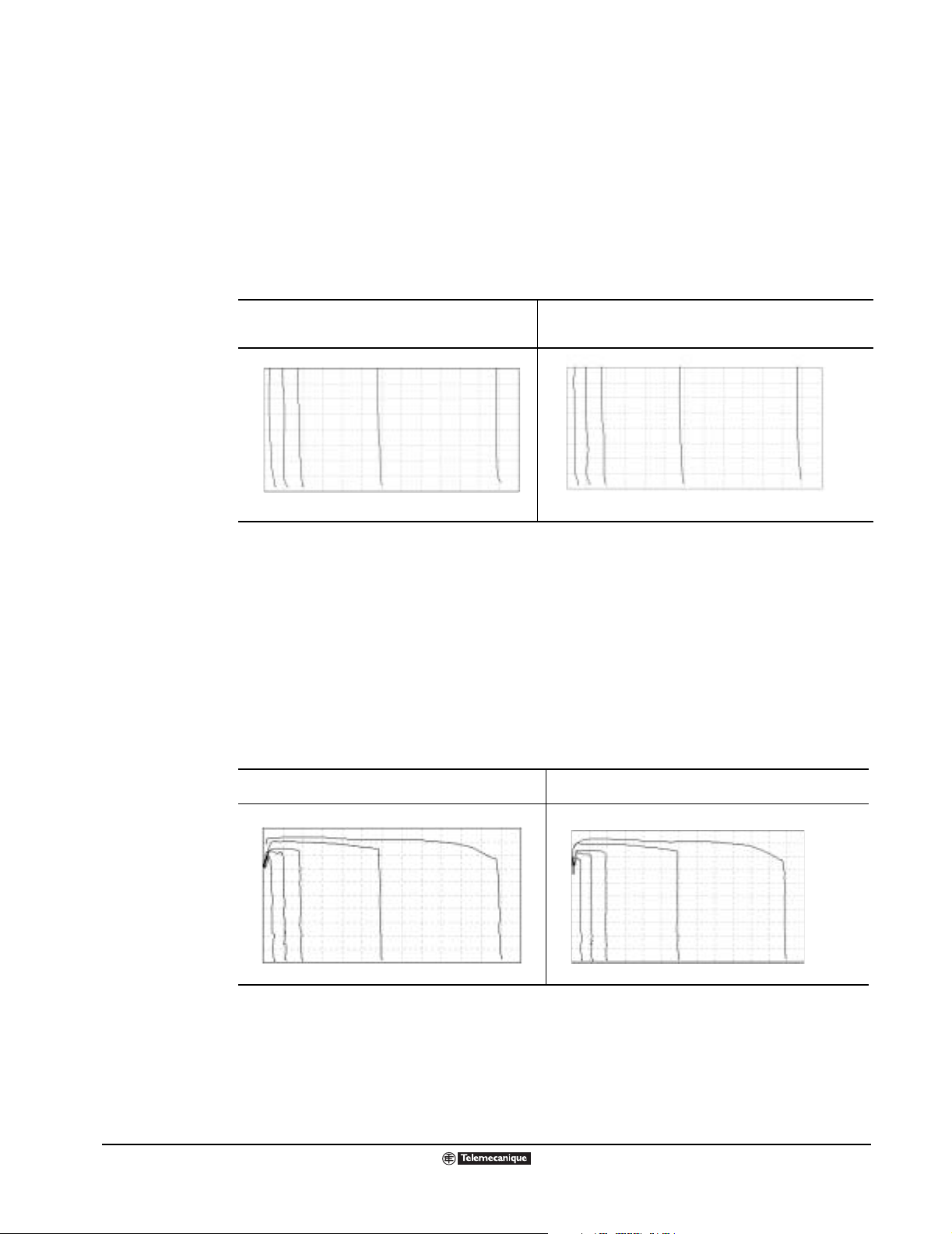
Altivar
®
58 TRX AC Drives
Speed Regulation (Constant Torque Rated Products)
SPEED REGULATION (CONSTANT TORQUE RATED PRODUCTS)
Figures 1 and 2 a re speed /torque pl ots of an ATV58 TRX Type H con troller op erati ng in c onstant t orque
mode with an off-the-shelf AC motor operating in open loop mode (without an encoder or tachometer
feedbac k from the motor) and in closed loop mode (with a 1024 pulse per re v oluti on encod er f ee dbac k
from the motor). To demonstrate the speed regulation capabilities, these plots were generated by
operating the drive from no loa d at z ero speed to ful l load at v a rious spee ds . The autotu ne feature was
configured. The ga in parame ter was adj usted to 50% and the sta bility par ameter w as adjuste d to 50%.
Note the speed regulatio n capability of th e ATV58 TRX drive controller as exhi bited by the portion of the
speed torque curve that is nearly perpendicular to the Y-axis.
Figure 1: ATV58 TRX Type H Controller Open Loop
Speed Regulat ion: 0.5 s T ransi tion fr om No Loa d to 100 %
Load
Percentage of Rated Torque
100%
75%
50%
25%
0%
036 10 20 30 40 50 60 Hz
Figure 2: ATV58 TRX Type H Controller w/ Digital Encoder Card
Speed Regulation: 0.5 s Transition from No Load to 100% Load
Percentage of Rated Torque
100%
75%
TypeHOpnSpd.eps
50%
25%
0%
036 10 20 30 40 50 60Hz
Typ e HEn cSpd .ep s
Maximum Transient Torque
Figures 3 and 4 are speed/torq ue pl ots of an ATV58 TRX Ty pe H driv e c ontro ll er ope rating in constant
torque mode with an off-the-shelf AC motor operating in open loop mode (without an encoder or
tachometer fee dback from the motor) an d in closed loop mode (with a 10 24 pulse per re volution encode r
feedbac k from the motor). To de monstrate th e torque prod ucing capabiliti es, these p lots were gen erated
by operating the drive from no load at z ero speed to maximum transient torque at various speeds. The
autotune fea ture was configured. Th e g ain pa ra me ter was adjusted to 50 % and the stability par a me ter
was adjusted to 50%. The available overtorque is a function of the motor design category. For typical
NEMA Design B motors, the ATV58 TRX controller can deli ver 200% of the nomin al mo tor to rqu e for 2
seconds, and 170% for 60 seconds.
Note the 200% transient torque produced by the ATV58 TRX Type H model, and note the torque
producing capabiliti es at very low speeds.
Figure 3: ATV58 TRX Type H Controller Open Lo op
Maximum Transient Torque
Percentage of Rated Torque
250%
200%
150%
100%
50%
0%
036 10 20 30 40 50 60 Hz
Operation in overspeed:
• In overspeed operation, the voltage no longer increases with the frequency, resulting in reduced
induction in the motor wh ich result s in loss of torque . C onsul t the motor man uf a cturer to en sure tha t
the motor can operate in overspeed.
• For a special motor , the nominal freq uency and the maxi mum frequency ca n be adjusted bet ween 10
and 500 Hz using the keypad display, PowerSuite, or Commissioning software.
96
© 2000–2003 Schneider Electric All Rights Reserved
Figure 4: ATV58 TRX Type H Controller w/ Digital Encoder
Card, Maximum Transient Torque
Percentage of Rated Torque
250%
200%
TypeHOpnTrq.eps
150%
100%
50%
0%
036 10 20 30 40 50 60 Hz
TypeHEncTrq.eps
09/2003
Page 97

h
d d
h
h = 50 mm (2 in) for:
HU09M2 to HU72M2
HU18N4 to HU90N4
HU90M2 to HD12M2
HD12N4 to HD23N4
h = 100 mm (4 in) for:
HD16M2X to HD46M2X
HD28N4 to HD79N4
HD28N4X to HD79N4X
HC10N4X to HC33N4X
Minimum
Clearances
Removing the
Protective Cover
Altivar
®
58 TRX AC Drives
Installation Recommendations
INSTALLATION RECOMMENDATIONS
• The A TV5 8 TRX drive co ntroller must be installed in a suitab le enviro nment. The en vironment ar ound
the drive controller must not exceed pollution degree requirements as defined in NEMA ICS-1
Clearances.eps
Appendix A or EN60664/IEC60664.
• Install the drive controller vertically (±10°) with the power terminals at the bottom. Avoid placing the
drive controller near any heat sources.
• Installation of a disconnect switch between the input line and the drive controller should be in
accordance with national and local codes.
• Overcurrent protection is required. Refer to page 113 for recommended fuses.
• The figure to the left shows the minimum clearances required around each drive controller for
unobstructed air flow. Also, leave at least 0.4 in. (1 0 mm) in front of the dr ive controller. These
clearances should not be used as minimum enclosure size for proper thermal dissipation.
Depending on the ambient temperatures in which the ATV58 TRX controller is used, the clearance
on the sides of the controller (dimension d in the drawing), and the particular ATV58 TRX model,
removal of the protective cover or adding a fan may be required; see the table below for more
information.
Temperature
–10 to +40°C (14 to 104 °F) 40 to 50°C (104 to 122 °F) 50 to 60°C (122 to 140 °F)
Add control card fan kit
VW3A5882• (see page 33 for
more information) and derate
the rated operating current by
2.2% for each °C over 50 °C.
Unacceptable mounting
clearance.
Do not install where the ambient
temperature exceeds 50 °C
(122 °F).
Do not install where the ambient
temperature exceeds 50 °C
(122 °F).
Do not install where the ambient
temperature exceeds 50 °C
(122 °F).
Unacceptable mounting
clearance.
Do not install where the ambient
temperature exceeds 50 °C
(122 °F).
from the top of the controller
(see graphic to th e le ft). Deg ree
of protection becomes IP20.
from the top of the controller
(see graphic to th e le ft). Deg ree
of protection becomes IP20.
clearance.
from the top of the controller
(see graphic to the left). Degree
of protection becomes IP20.
Add control card fan kit
VW3A5882• (see page 33 for
more information).
from the drive (see graphic to
the left). Degree of protection
becomes IP20. Also derate the
rated operating curre nt b y 2.2%
for each °C over 40 °C.
Add control card fan kit
VW3A5882• (see page 33 for
more information) and derate
the rated operating current by
2.2% for each °C over 40 °C.
VW3A5882• (see page 33 for
more information) and derate
the rated operating current by
2.2% for each °C over 40 °C.
Unacceptable mounting
clearance.
temperature exceeds 40 °C
(109 °F).
RemoveCvr.eps
ATV58 TRX Model Dimension d
HU09M2 to HU72M2
HU18N4 to HU90N4
HU90M2 to HD12M2
HD12N4 to HD23N4
HD16M2X to HD46M2X
HD28N4 to HD79N4
HD28N4X to HD79N4X
HC10N4X to HC33N4X < 50 mm (2 in) No special precautions needed. Do not install where the ambient
≥ 50 mm (2 in) No special precautions needed. Remove the protective cover
< 50 mm (2 in) Remove the protective cover
≥ 50 mm (2 in) No special precautions needed. Remove the protective cover
< 50 mm (2 in) Remove the protective cover
≥ 50 mm (2 in) No special precautions needed. Add control card fan kit
< 50 mm (2 in) Unacceptable mounting
09/2003
© 2000–2003 Schneider Electric All Rights Reserved
97
Page 98
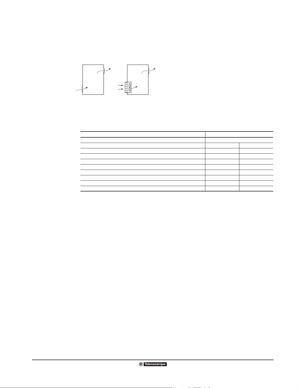
Altivar
®
58 TRX AC Drives
Installation Recommendations
Mounting in a General-Purpose Metal Enclosure
T o ens ure sufficien t air circulation whe n mounting an ATV58 TRX drive in a general-purpose enclos ure,
observe the following:
• Provide ventilation inlets and outlets in the enclosure (see the figure below).
VentEnc.eps
free air flow
with fan and filter
mounted on enclosure
• If the enclosure does not provide sufficient free air flow, install an enclosure ventilation fan with
IP54/NEMA 12 filters to e xhaust he at outside of the enclosure (see the figure abo v e). The enc losure
fan should ha v e a greater fan flow rate tha n the driv e contro ller f an flow rate lis ted in the tab l e belo w.
ATV58 TRX Model Fan Flow Rate
ATV58HU09M2, ATV58U18M2 Non-Ventilated
ATV58HU29M2, ATV58U18N4, ATV58U29N4, ATV58U41N4, ATV58U54N4 36 m3/hour 21 CFM
ATV58HU41M2 47 m3/hour 27.5 CFM
ATV58HU54M2, ATV58U72M2, ATV58U54N4, ATV58U72N4, ATV58U90N4 72 m3/hour 42 CFM
ATV58HU90M2, ATV58D12M2, ATV58D12N4, ATV58D16N4, ATV58D23N4 72 m3/hour 42 CFM
ATV58HD16M2, ATV58D23M2, ATV58D28N4, ATV58D33N4, ATV58D46N4 161 m3/hour 94 CFM
ATV58HD28M2, ATV58D33M2, ATV58D46M2, ATV58D54N4, ATV58D64N4, ATV58D79N4 343 m3/hour 200 CFM
ATV58HC10N4X 600 m3/hour 350 CFM
ATV58HC13N4X, C15N4X, C19N4X 900 m3/hour 525 CFM
ATV58HC23N4X, C25N4X, C28N4X, C31N4X, C33N4X 900 m3/hour 525 CFM
• If there is a possi bility of condensa tion, k eep the control su pply s wi tched on d uring periods wh en the
motor is not running, or install thermostatically controlled strip heaters.
Mounting in a Type 12 or IP54 Metal Enclosure
Certain conditions may require Type 12 or IP54 protection, such as dust, corrosive gas, high humidity
with the risk of condensati on and dripping water. When mou nting in a Type 12 or IP54 enclosure, f o llow
the installation recommendations given on page 97.
If the enclosure is non-ventilated, use a stirring fan to circulate the air inside the enclosure to prevent
hot spots from forming. Wi th a stirring f an, the ma xi mum tem pera ture inside the enclo sure can then be
up to 60 °C (140 °F), althoug h the current mu st be derate d by 2.2% per °C abov e 50 °C . If condens ation
might form within the enclosure, keep the power supply switched on during periods when the motor is
not running, or install thermostatically controlled strip heaters.
98
© 2000–2003 Schneider Electric All Rights Reserved
09/2003
Page 99

Altivar
®
58 TRX AC Drives
Installation Recommendations
Calculating Enclosure Size
The equation f or c alculating Rth (°C/W ), the maxim um all owab le t hermal resi stance of the en closure , is:
T
Max. internal ambient temp. (°C) around drive controller=
o
Rth Thermal resistance of the enclosure (calculated previously)=
K Thermal resistance per square inch of the enclosure.=
i
T
o
P Total power dissipated in enclosure (W)=
Max. external temp. (°C) around enclosure=
2
), of a wall-mounted enclosure generally consists of the sides,
TiT
–
---------------- -
=
Rth
P
Useful heat e xchange surf ace ar ea, S (in
top, and front. The minimum surface area required for a drive controller enclosure is calculated as
follows.
NOTE: Contact enclosure manufacturer for K factors.
K
S
--------- -=
Rth
Consider the following points when sizing the enclosure:
• Use only metallic enclosures since they have good thermal conduction.
• This procedure does not consider radiant or con vected heat loa d from external sources . Do not install
enclosures where external heat sources (such as direct sunlight) can add to enclosure heat load.
• If additional devices are present inside the enclosure, consider the heat load of the devices in the
calculation.
• The actual useful area for convection cooling of t he e nc los ure will vary depending upon th e m eth od
of mounting. The me thod of mounti ng mus t allo w f or fr ee air mo v em ent o v er al l surfaces consider ed
for convection cooling.
The following example illustrates calculation of the enclosure size for an ATV58HU29N4 (2 HP) drive
controller mounted in a Type 12 enclosure.
• Maximum external temperature: T
= 25 °C
o
• Power dissipated inside enclosure: P = 97 W (from ratings tables; see page 10)
• Maximum internal temperature: Ti = 40 °C
• Thermal resistance per square inch of enclosure: K = 186
• Calculate maximum allowable thermal resistance, Rth:
40 °C 25 °C–
Rth
------------------------------------0.16°C/W==
97 W
• Calculate minimum useful heat exchange surface area, S:
186
S
----------- 11 6 2 . 5 i n
==
0.16
2
Useful heat exchange surface area (S) of the proposed wall-mounted enclosure:
• Height: 24 in (610 mm)
• Width: 20 in (508 mm)
• Depth: 12 in (305 mm)
front area top area side area
S2420×()20 12×()224 12×()+ + 1296 in
==
Since the surf ace area of the enclosure i s great er than the mini mum requi red surf ace area (1162 .5 in
2
2
the enclosure is sufficiently large for this particular ATV58 TRX model.
Note that if the selected encl osure did not pro vide the req uired sur fac e area or did not meet ap plication
needs, then the following would need to be considered:
• Use a larger enclosure.
• Add a passive heat exchanger to the enclosure.
• Add an air conditioning unit to the enclosure.
),
09/2003
© 2000–2003 Schneider Electric All Rights Reserved
99
Page 100

Altivar
®
58 TRX AC Drives
Wiring Recommendations
WIRING RECOMMENDATIONS
Good wiring practice requires th e separ ation of c ontrol circ uit wiring from all po wer wiring. P o wer wiring
to the motor must ha v e the m axim um possib le sepa ratio n from all other po we r wiring , whethe r from the
same drive controller or other drive controllers; do not run power and/or control or multiple power
wiring in the same conduit. This separation reduces the possibility of coupling electrical transients
from power circuits into control circuits or from motor power wiring into other power circuits.
Follow the practices below when wiring enclosed ATV58 TRX drive controllers:
• When using metallic conduit, use metal conduit kits; see page 33 for a list of conduit kits.
• Use metallic conduit for all controller wiring.
• Do not run control and power wiring in the same conduit.
• Do not run output wiring from more than one drive in the same conduit.
• Separate metallic condu its carrying po wer w iring or lo w-level contro l wiring b y at leas t 3 in. (76 m m).
• Separate non-metallic conduits or cable trays used to carry power wiring from metallic conduit
carrying low-level control wiring by at least 12 in. (305 mm).
• Whenever power and control wiring cross, the metallic conduits and non-metallic conduits or trays
must cross at right angles.
• Equip all inducti ve ci rcuits near the d rive (rela ys , contactors , solenoid v alv es) with no ise suppresso rs
or connect them to a separate circuit.
Recommendations for Wire Sizing
Refer to NEC Article 430 for the sizing of the branch circuit conductors. All branch circuit components
and equipment (su ch as tra nsf ormers , feeder cab les , disconn ect de vi ces , an d pr otecti v e devices) mus t
be rated for the input current of the ATV58 TRX drive controller or the rated output current, whichever
value is larger. The input current of the controller depends on the impedance of the power
distribution system and the available fault current at the drive input terminals.
Select the input c urrent correspond ing to the a v ailable short circuit curr ent capability (AIC Rating) or the
line impedance pr esent. If t he av ai labl e f ault curren t capabi lity of th e bra nch circui t is limi ted b y fuses or
circuit breake rs (not system impedan ce), use th e av aila ble f aul t current ca pability on the line side of the
fuses or circuit breakers to select the drive controller input current. The input current values for the
variable torque drive controller ratings are based on nomin al NEC ra ted motor cu rrent s . The input
current valu es for the consta nt to rque drive control ler ratings are b as ed on drive con trol le r r at ed output
currents. The tables on the following pages provide input current information to optimally size branch
circuit conductors.
100
© 2000–2003 Schneider Electric All Rights Reserved
09/2003
 Loading...