

Page 1
2354235 11/2008
Altivar 12
Variable speed drives for
asynchronous motors
User manual
05/2010
BBV28581
www.schneider-electric.com
Page 2

Page 3

Contents
Contents ____________________________________________________________________________________________________ 3
Important information __________________________________________________________________________________________ 4
Before you begin______________________________________________________________________________________________ 5
Documentation structure________________________________________________________________________________________ 7
Software enhancements________________________________________________________________________________________ 8
Steps for setting up (also refer to Quick Start) _______________________________________________________________________ 9
Setup - Preliminary recommendations ____________________________________________________________________________ 10
Drive ratings ________________________________________________________________________________________________ 11
Dimensions and weights_______________________________________________________________________________________ 12
Mounting___________________________________________________________________________________________________ 13
Wiring _____________________________________________________________________________________________________ 16
Power terminals _____________________________________________________________________________________________ 20
Control terminals_____________________________________________________________________________________________ 23
Check list __________________________________________________________________________________________________ 29
Factory configuration _________________________________________________________________________________________ 30
Basic functions ______________________________________________________________________________________________ 31
Programming _______________________________________________________________________________________________ 32
Structure of parameter tables___________________________________________________________________________________ 35
Function compatibility table ____________________________________________________________________________________ 36
Reference Mode rEF _________________________________________________________________________________________ 37
Monitoring mode MOn ________________________________________________________________________________________ 38
Configuration Mode ConF______________________________________________________________________________________ 44
Configuration Mode - MyMenu __________________________________________________________________________________ 45
Configuration Mode - Complete menu (FULL) ______________________________________________________________________ 47
Maintenance ________________________________________________________________________________________________ 99
Migration ATV11 - ATV12_____________________________________________________________________________________ 100
Diagnostics and Troubleshooting _______________________________________________________________________________ 107
Application notes ___________________________________________________________________________________________ 113
Applicative notes____________________________________________________________________________________________ 116
Wiring ____________________________________________________________________________________________________ 120
Organization tree ___________________________________________________________________________________________ 121
Parameter index ____________________________________________________________________________________________ 122
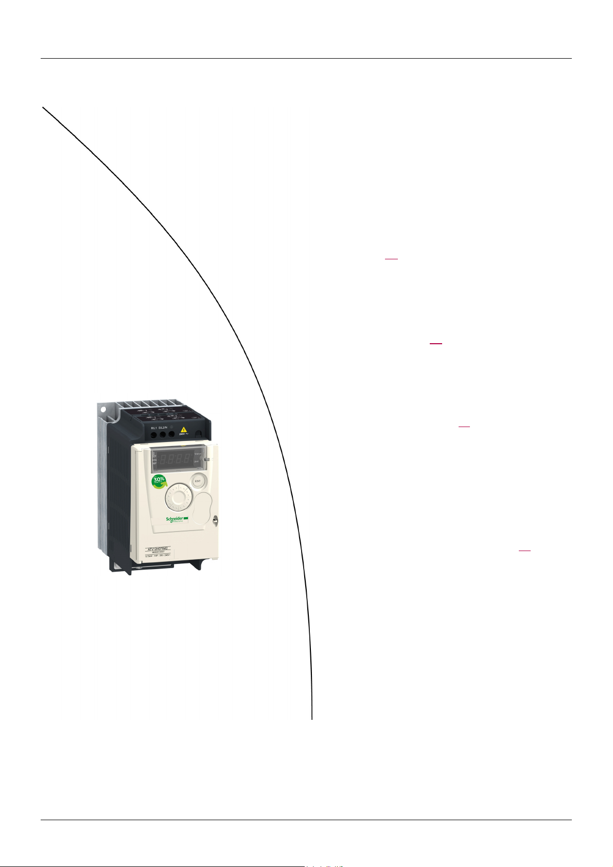
Energy savings
Speed control process regulating enables significant energy savings, particulary with pump and fan applications.
Furthermore some ATV12 functions enable to enhance these savings: [Motor control type] (Ctt) page
(tLS) page
BBV28581 05/2010 3
74 and [PID feedback assignment] (PIF) page 72.
57, [Sleep/wake]
Page 4
Important information
NOTICE
Read these instructions carefully, and look at the equipment to become familiar with the device before trying to install, operate, or maintain
it. The following special messages may appear throughout this documentation or on the equipment to warn of potential hazards or to call
attention to information that clarifies or simplifies a procedure.
The addition of this symbol to a Danger or Warning safety label indicates that an electrical hazard exists, which will result in
personal injury if the instructions are not followed.
This is the safety alert symbol. It is used to alert you to potential personal injury hazards. Obey all safety messages that follow
this symbol to avoid possible injury or death.
DANGER
DANGER indicates an imminently hazardous situation, which, if not avoided, will result in death or serious injury.
WARNING
WARNING indicates a potentially hazardous situation, which, if not avoided, can result in death, serious injury or
equipment damage.
CAUTION
CAUTION indicates a potentially hazardous situation, which, if not avoided, can result in injury or equipment
damage.
CAUTION
CAUTION, used without the safety alert symbol, indicates a potentially hazardous situation which, if not avoided,
can result in equipment damage.
PLEASE NOTE
The word "drive" as used in this manual refers to the controller portion of the adjustable speed drive as defined by NEC.
Electrical equipment should be installed, operated, serviced, and maintained only by qualified personnel. No responsibility is assumed by
Schneider Electric for any consequences arising out of the use of this product.
© 2009 Schneider Electric. All Rights Reserved.
4 BBV28581 05/2010
Page 5

Before you begin
Read and understand these instructions before performing any procedure with this drive.
DANGER
HAZARD OF ELECTRIC SHOCK, EXPLOSION, OR ARC FLASH
• Read and understand this manual before installing or operating the Altivar 12 drive. Installation, adjustment, repair, and maintenance
must be performed by qualified personnel.
• The user is responsible for compliance with all international and national electrical code requirements with respect to grounding of
all equipment.
• Many parts of this drive, including the printed circuit boards, operate at the line voltage. DO NOT TOUCH. Use only electrically
insulated tools.
• DO NOT touch unshielded components or terminal strip screw connections with voltage present.
• DO NOT short across terminals PA/+ and PC/– or across the DC bus capacitors.
• Before servicing the drive:
- Disconnect all power, including external control power that may be present.
- Place a “DO NOT TURN ON” label on all power disconnects.
- Lock all power disconnects in the open position.
- WAIT 15 MINUTES to allow the DC bus capacitors to discharge.
- Measure the voltage of the DC bus between the PA/+ and PC/– terminals to ensure that the voltage is less than 42 Vdc.
- If the DC bus capacitors do not discharge completely, contact your local Schneider Electric representative. Do not repair or
operate the drive.
• Install and close all covers before applying power or starting and stopping the drive.
Failure to follow these instructions will result in death or serious injury.
DANGER
UNINTENDED EQUIPMENT OPERATION
• Read and understand this manual before installing or operating the Altivar 12 drive.
• Any changes made to the parameter settings must be performed by qualified personnel.
Failure to follow these instructions will result in death or serious injury.
WARNING
DAMAGED DRIVE EQUIPMENT
Do not operate or install any drive or drive accessory that appears damaged.
Failure to follow these instructions can result in death, serious injury, or equipment damage.
BBV28581 05/2010 5
Page 6

Before you begin
WARNING
LOSS OF CONTROL
• The designer of any control scheme must
- consider the potential failure modes of control paths and, for certain critical control functions,
- provide a means to achieve a safe state during and after a path failure.
Examples of critical control functions are emergency stop and overtravel stop.
• Separate or redundant control paths must be provided for critical control functions.
• System control paths may include communication links. Consideration must be given to the implications of unanticipated
transmission delays or failures of the link.
Failure to follow these instructions can result in death, serious injury, or equipment damage.
a. For additional information, refer to NEMA ICS 1.1 (latest edition), “Safety Guidelines for the Application, Installation, and Maintenance of
Solid State Control” and to NEMA ICS 7.1 (latest edition), “Safety Standards for Construction and Guide for Selection, Installation and
Operation of Adjustable-Speed Drive Systems.”
a
CAUTION
INCOMPATIBLE LINE VOLTAGE
Before turning on and configuring the drive, ensure that the line voltage is compatible with the supply voltage range shown on the drive
nameplate. The drive may be damaged if the line voltage is not compatible.
Failure to follow these instructions can result in injury or equipment damage.
Using motors in parallel
Set Motor control type Ctt page 57 to Std.
CAUTION
RISK OF DAMAGE TO THE MOTOR
Motor thermal protection is no longer provided by the drive. Provide an alternative means of thermal protection on every motor
Failure to follow these instructions can result in equipment damage
6 BBV28581 05/2010
Page 7

Documentation structure
The following Altivar 12 technical documents are available on the Schneider Electric website (www.schneider-electric.com) as well as on
DVD-ROM (reference VW3A8200).
User manual
This manual describes how to install, commission, operate and program the drive.
Quick Start
The Quick Start describes how to wire and configure the drive to start motor quickly and simply for simple applications. This document is
delivered with the drive.
Modbus Communication manual
This manual describes the assembly, connection to the bus or network, signaling, diagnostics, and configuration of the communicationspecific parameters via the 7-segment LED display.
It also describes the communication services of the Modbus protocol.
This manual includes all Modbus addresses. It explains the operating mode specific to communication (state chart).
ATV12P manual
This manual describes the specific features of ATV12P drives.
BBV28581 05/2010 7
Page 8

Software enhancements
Since it was first marketed, the Altivar ATV 12 has been equipped with additional functions. Software version V1.1 has now been updated
to V1.2. This documentation relates to version V1.2.
The software version appears on the rating plate attached to the side of the drive.
Enhancements made to version V1.2 in comparison to V1.1
• New parameters:
- Sleep threshold Offset SLE. See page 75
- PI feedback supervision threshold LPI. See page 76
- PI feedback supervision function time delay tPI. See page 76
- Maximum frequency detection hysteresis AP0. See page 76
- PI feedback supervision MPI. See page 76
- Fallback speed LFF. See page 76
- Time delay before automatic start for the overload fault FtO. See page 77
- Time delay before automatic start for the underload fault FtU. See page 78
- Selecting the operating mode MdE. See page 78
- Starting frequency of the auxiliary pump FOn. See page 78
- Time delay before starting the auxiliary pump tOn. See page 78
- Ramp for reaching the auxiliary pump nominal speed rOn. See page 78
- Auxiliary pump stopping frequency FOF. See page 78
- Time delay before the auxiliary pump stop command tOF. See page 79
- Ramp for auxiliary pump stopping rOF. See page 79
- Zero flow detection period nFd. See page 79
- Zero flow detection activation threshold FFd. See page 79
- Zero flow detection offset LFd. See page 79
•New menu Pump sub-menu PMP-. See page 77
• New quick REMOTE/LOCAL configuration switching using the embedded buttons. See page 34
.
.
.
.
.
.
.
.
.
.
.
.
.
.
.
.
.
.
. For pumping applications.
.
8 BBV28581 05/2010
Page 9
Steps for setting up (also refer to Quick Start)
1. Receive and inspect the drive
v Check that the part number printed on the label is the same as that on the
purchase order.
v Remove the Altivar from its packaging and check that it has not been damaged
in transit.
2. Check the line voltage
v Check that the line voltage is compatible with the voltage
range of the drive (page 11
3. Mount the drive
v Mount the drive in accordance with the instructions
Steps 2 to 4 must
be performed with
in this document (page 13
v Install any options required.
).
).
the power off.
4. Wire the drive
v Connect the motor, ensuring that its
connections correspond to the voltage.
v Connect the line supply, after making
sure that the power is off.
v Connect the control part.
(page 20)
5. Configure the drive (page 32)
v Apply input power to the drive but
do not give a run command.
v Set the motor parameters
(in Conf mode) only if the factory
configuration of the drive is not
suitable.
v Perform auto-tuning.
6. Start
BBV28581 05/2010 9
Page 10

Setup - Preliminary recommendations
Prior to switching on the drive
DANGER
UNINTENDED EQUIPMENT OPERATION
Ensure that all logic inputs are inactive to help prevent an accidental startup.
Failure to follow these instructions will result in death or serious injury.
Prior to configuring the drive
DANGER
UNINTENDED EQUIPMENT OPERATION
• Read and understand this manual before installing or operating the Altivar 12 drive.
• Any changes made to the parameter settings must be performed by qualified personnel.
• Ensure that all logic inputs are inactive to help prevent an accidental startup when modifying parameters.
Failure to follow these instructions will result in death or serious injury.
Using the drive with motor having a different size
The motor could have different rating than drive. In case of smaller motor, there is no specific calculation. The motor current has to be set
on Motor thermal current ItH parameter page 94
on a 2.2 kW (3 HP) drive) it is necessary to ensure motor current and actual motor power will not pass over nominal power of drive.
. In case of higher size of motor, possible up to 2 sizes (example is using a 4 kW (5.5 HP)
Line contactor
CAUTION
RISK OF DAMAGE TO THE DRIVE
• Avoid operating the contactor frequently to avoid premature aging of the filter capacitors.
• Power cycling must be MORE than 60 seconds.
Failure to follow these instructions can result in equipment damage.
Use with a smaller rated motor or without a motor
• In factory settings mode, Output Phase loss OPL page 94 is active (OPL set to YES). To check the drive in a test or maintenance
environment without having to switch to a motor with the same rating as the drive (particularly useful in the case of high power drives),
deactivate Output Phase loss OPL (OPL set to nO).
•Set Motor control type Ctt page 57
to Std in Motor control menu drC-.
CAUTION
RISK OF DAMAGE TO THE MOTOR
Motor thermal protection will not be provided by the drive if the motor rating current is less than 20% of the rated drive current. Provide
an alternative means of thermal protection.
Failure to follow these instructions can result in equipment damage.
10 BBV28581 05/2010
Page 11

Drive ratings
Single-phase supply voltage: 100…120 V 50/60 Hz
For three Phase Output 200/240 V motors
Motor Line supply (input) Drive (output) Reference
Power indicated
on plate (1)
kW HP A A kVA W A A A
0.18 0.25 6 5 1 18 1.4 2.1 2.3 ATV12H018F1 1C1
0.37 0.5 11.4 9.3 1.9 29 2.4 3.6 4 ATV12H037F1 1C1
0.75 1 18.9 15.7 3.3 48 4.2 6.3 6.9 ATV12H075F1 2C1
Maximum line current Apparent
power
at 100 V at 120 V
Power
dissipated
at nominal
current (1)
Nominal
current
In
Max. transient
current for
60 s 2 s
(2)
Single-phase supply voltage: 200…240 V 50/60 Hz
For three Phase Output 200/240 V motors
Motor Line supply (input) Drive (output) Reference
Power indicated
on plate (1)
kW HPAAkVAW A A A
0.18 0.25 3.4 2.8 1.2 18 1.4 2.1 2.3 ATV12H018M2 1C2
0.37 0.5 5.9 4.9 2 27 2.4 3.6 4 ATV12H037M2 1C2
0.55 0.75 8 6.7 2.8 34 3.5 5.3 5.8 ATV12H055M2 1C2
0.75 1 10.2 8.5 3.5 44 4.2 6.3 6.9 ATV12H075M2 1C2
1.5 2 17.8 14.9 6.2 72 7.5 11.2 12.4 ATV12HU15M2 2C2
2.2 3 24 20.2 8.4 93 10 15 16.5 ATV12HU22M2 2C2
Maximum line current Apparent
power
at 200 V at 240 V
Power
dissipated
at nominal
current (1)
Nominal
current
In
Max. transient
current for
60 s 2 s
(2)
Three-phase supply voltage: 200…240 V 50/60 Hz
For three Phase Output 200/240 V motors
Size
(3)
Size
(3)
Motor Line supply (input) Drive (output) Reference
Power indicated
on plate (1)
kW HPAAkVAWA A A
0.18 0.25 2 1.7 0.7 16 1.4 2.1 2.3 ATV12H018M3 1C3
0.37 0.5 3.6 3 1.2 24 2.4 3.6 4 ATV12H037M3 1C3
0.75 16.3 5.3 2.2 41 4.2 6.3 6.9 ATV12H075M3 1C3
1.5 2 11.1 9.3 3.9 73 7.5 11.2 12.4 ATV12HU15M3 2F3
2.2 3 14.9 12.5 5.2 85 10 15 16.5 ATV12HU22M3 2F3
3 4 19 15.9 6.6 94 12.2 18.3 20.1 ATV12HU30M3 3F3
4 5.5 23.8 19.9 8.3 128 16.7 25 27.6 ATV12HU40M3 3F3
(1)These power ratings are for a switching frequency of 4 kHz, in continuous operation. The
switching frequency is adjustable from 2 to 16 kHz.
Above 4 kHz, the drive will reduce the switching frequency if an excessive temperature rise
occurs. The temperature rise is detected by a probe in the power module. Nonetheless,
derating should be applied to the nominal drive current if continuous operation above 4 kHz
is required:
• 10% derating for 8 kHz
• 20% derating for 12 kHz
• 30% derating for 16 kHz
(3)Size description
possible values
Maximum line current Apparent
power
at 200 V at 240 V
2 F3
physical size 1
1
physical size 2
2
physical size 3
3
possible values
Power
dissipated
at nominal
current (1)
FCFlat
Compact
Nominal
current
In
Max. transient
current for
60 s 2 s
(2)Reference description,
possible values
(2)
example: ATV12HU15M3
ATV12: Altivar 12;
H: product on heatsink;
U15: drive power rating,
see nCU parameter page 41
M3: drive voltage rating,
see UCAL parameter page 41
100 V 1 phase
1
200 V 1 phase
2
200 V 3 phase
3
Size
(3)
;
.
BBV28581 05/2010 11
Page 12
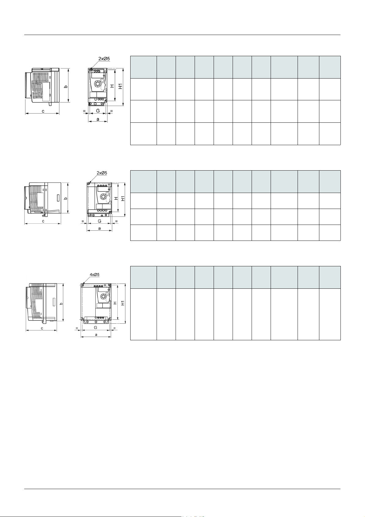
Dimensions and weights
ATV12H018F1, 018M2, 037F1, 037M2, 037M3, 018M2, 018M3, 055M2, 075M2
ATV12H075F1, U15M2, U22M2, U15M3, U22M3
ATV12H
018F1
018M2
018M3
037F1
037M2
037M3
055M2
075M2
075M3
ATV12H
075F1
U15M2
U22M2
U15M3
U22M3
a
mm
(in.)
72
(2.83)
72
(2.83)
72
(2.83)
a
mm
(in.)
105
(4.13)
105
(4.13)
105
(4.13)
b
mm
(in.)
142
(5.59)
130
(5.12)
130
(5.12)
b
mm
(in.)
130
(5.12)
130
(5.12)
130
(5.12)
c
mm
(in.)
102.2
(4.02)60(2.36)
121.2
(4.77)60(2.36)
131.2
(5.17)60(2.36)
c
mm
(in.)
156.2
(6.15)93(3.66)
156.2
(6.15)93(3.66)
131.2
(5.17)93(3.66)
G
mm
(in.)
G
mm
(in.)
H
mm
(in.)
131
(5.16)
120
(4.72)
120
(4.72)
H
mm
(in.)
120
(4.72)
120
(4.72)
120
(4.72)
H1
mm
(in.)
143
(5.63)
143
(5.63)
143
(5.63)
H1
mm
(in.)
142
(5.59)
142
(5.59)
143
(5.63)
Ø
mm
(in.)
2 x 5
(2 x 0.20)
2 x 5
(2 x 0.20)
2 x 5
(2 x 0.20)
Ø
mm
(in.)
2 x 5
(2 x 0.20)
2 x 5
(2 x 0.20)
2 x 5
(2 x 0.20)
For
screws
M4
M4
M4
For
screws
M4
M4
M4
Weight
kg
(lb)
0.7
(1.5)
0.8
(1.8)
0.8
(1.8)
Weight
kg
(lb)
1.3
(2.9)
1.4
(3.1)
1.2
(2.6)
ATV12HU30M3, U40M3
ATV12H
U30M3
U40M3
a
mm
(in.)
140
(5.51)
b
mm
(in.)
170
(6.69)
c
mm
(in.)
141.2
(5.56)
G
mm
(in.)
126
(4.96)
H
mm
(in.)
159
(6.26)
H1
mm
(in.)
184
(7.24)
Ø
mm
(in.)
4 x 5
(2 x 0.20)
For
screws
M4
Weight
kg
(lb)
2.0
(4.4)
12 BBV28581 05/2010
Page 13
Mounting
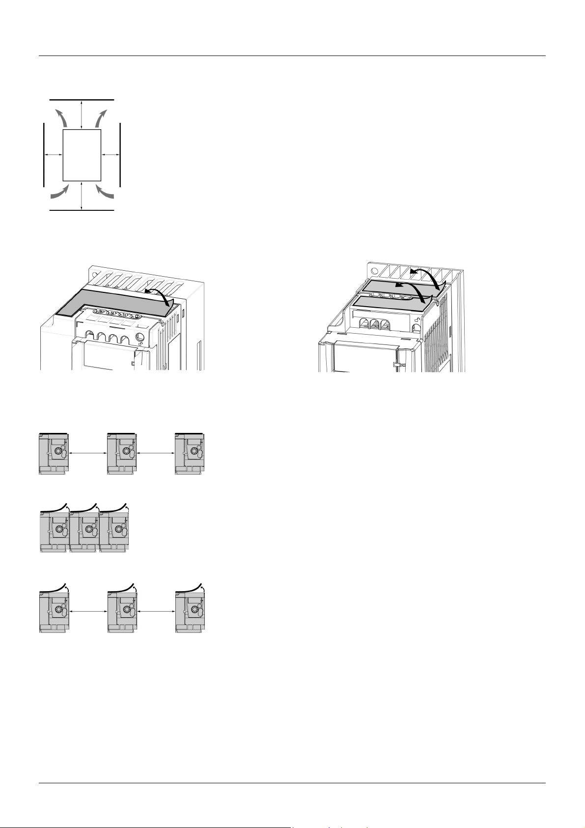
Mounting and temperature conditions
Install the unit vertically, at ± 10°.
Do not place it close to heating elements.
≥ 50 mm
(2 in)
≥ d
≥ 50 mm
(2 in)
Removing the vent cover(s)
Leave sufficient free space to ensure that the air required for cooling purposes can circulate from the bottom to the
top of the unit.
≥ d
Free space in front of unit: 10 mm (0.4 in.) minimum.
We recommend that the drive is installed on a dissipative surface.
Mounting types
Type A mounting
≥ 50 mm
(2 in.)
Type B mounting
Type C mounting
≥ 50 mm
(2 in.)
With these types of mounting, the drive can be used up to an ambient temperature of 50°C (122°F), with a switching frequency of 4 kHz.
Fanless drives need derating.
≥ 50 mm
(2 in.)
≥ 50 mm
(2 in.)
Free space ≥ 50 mm (2 in.) on each side, with vent cover fitted. Mounting type A is
suitable for drive operation at surrounding air temperature less than or equal to 50°C
(122°F).
Drives mounted side-by-side, vent cover should be removed.
Free space ≥ 50 mm (2 in.) on each side. Vent cover should be removed for operation at
surrounding air temperature above 50°C (122°F).
BBV28581 05/2010 13
Page 14
Mounting
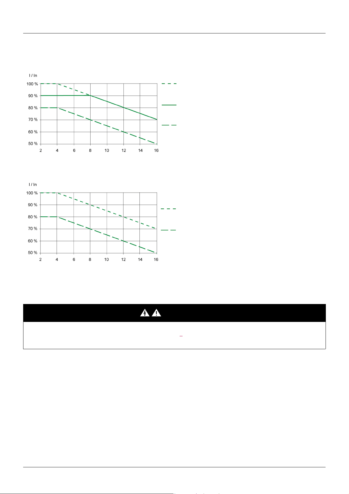
Derating curves
Derating curves for the nominal drive current (In) as a function of temperature, switching frequency and mounting type.
ATV12H0
ATV12HU
ppM2, ATV12H0ppM3, ATV12H018F1 to ATV12H037F1
40°C (104°F) mounting types A and C
50°C (122°F) mounting type C with metal plate
40°C (104°F) mounting type B
60°C (140°F) mounting type C with metal plate
Switching frequency in kHz
ppM2, ATV12H075F1, ATV12HU15M3 to ATV12HU40M3
50°C (122°F) mounting types A, B and C
60°C (140°F) mounting types A, B and C
Switching frequency in kHz
For intermediate temperatures (e.g. 55°C (131°F)), interpolate between two curves.
Bus voltage measurement procedure
DANGER
HAZARD OF ELECTRIC SHOCK, EXPLOSION, OR ARC FLASH
Read and understand the precautions in “Before you begin” on page 5 before performing this procedure.
Failure to follow these instructions will result in death or serious injury.
14 BBV28581 05/2010
Page 15
Mounting
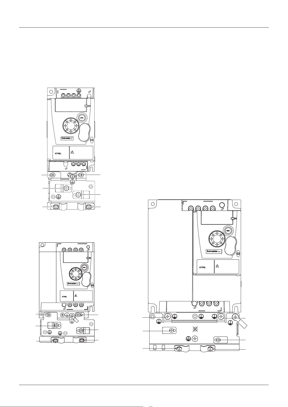
Installing the EMC plates
EMC mounting plate: size 1 VW3A9523, size 2 VW3A9524 or size 3 VW3A9525 to be ordered
separately
Mount the EMC mounting plate to the holes in the ATV12 using the 2 screws supplied, as shown in the drawings below.
Size 1, plate reference VW3A9523:
ATV12H018F1, ATV12H037F1, ATV12P037F1,
ATV12H018M2, ATV12
p0ppM2, ATV12p0ppM3
1. 2 mounting screws
2. 4 x M4 screws for attaching EMC clamps
1
2
2
Size 2, plate reference VW3A9524:
ATV12H075F1, ATV12HU
ATV12
pU22M3
1
2
ppM2, ATV12pU15M3,
1
Size 3, plate reference VW3A9525:
ATV12
2
2
1
2
pU30M3 and ATV12pU40M3
1
2
1
2
BBV28581 05/2010 15
2
2
2
2
Page 16

Wiring
Recommendations
Keep the power cables separate from control circuits with low-level signals (detectors, PLCs, measuring apparatus, video, telephone).
Always cross control and power cables at 90° if possible.
Power and circuit protection
Follow wire size recommendations according to local codes and standards.
Before wiring power terminals, connect the ground terminal to the grounding screws located below the output terminals (see Access to the
motor terminals if you use ring terminals, page 21
.
The drive must be grounded in accordance with the applicable safety standards. ATV12
such the leakage current is over 3.5 mA.
When upstream protection by means of a "residual current device" is required by the installation standards, a type A circuit breaker should
be used for single-phase drives and type B for 3-phase drives. Choose a suitable model incorporating:
• HF current filtering
• A time delay which prevents tripping caused by the load from stray capacitance on power-up. The time delay is not possible for 30 mA
devices. In this case, choose devices with immunity against accidental tripping, for example RCDs with SI type leakage current
protection.
If the installation includes several drives, provide one "residual current device" per drive.
ppppM2 drives have an internal EMC filter, and as
Control
For control and speed reference circuits, we recommend using shielded twisted cables with a pitch of between 25 and 50 mm (1 and 2 in.),
connecting the shield to ground as outlined on page 26
.
Length of motor cables
For motor cable lengths longer than 50 m (164 ft) for shielded cables and longer than 100 m (328 ft) for unshielded cables, please use motor
chokes.
For accessory part numbers, please refer to the catalog.
Equipment grounding
Ground the drive according to local and national code requirements. A minimum wire size of 10 mm² (6 AWG) may be required to meet
standards limiting leakage current.
.
DANGER
HAZARD OF ELECTRIC SHOCK, EXPLOSION, OR ARC FLASH
• The drive panel must be properly grounded before power is applied.
• Use the provided ground connecting point as shown in the figure below.
Failure to follow these instructions will result in death or serious injury.
DANGER
ATV12H075F1, ATV12H075M2 AND ATV12H075M3 - GROUND CONTINUITY HAZARD
An anodized heatsink can create an insulation barrier to the mounting surface. Ensure that you follow the recommended grounding
connections.
Failure to follow these instructions will result in death or serious injury.
• Ensure that the resistance of the ground is one ohm or less.
• When grounding several drives, you must connect each one
directly, as shown in the figure to the left.
• Do not loop the ground cables or connect them in series.
16 BBV28581 05/2010
Page 17

Wiring
WARNING
RISK OF DRIVE DESTRUCTION
• The drive will be damaged if input line voltage is applied to the output terminals (U/T1,V/T2,W/T3).
• Check the power connections before energizing the drive.
• If replacing another drive, verify that all wiring connections to the drive comply with wiring instructions in this manual.
Failure to follow these instructions can result in death, serious injury or equipment damage.
WARNING
INADEQUATE OVERCURRENT PROTECTION
• Overcurrent protective devices must be properly coordinated.
• The Canadian Electrical Code and the National Electrical Code require branch circuit protection. Use the fuses recommended in this
manual, page 121
• Do not connect the drive to a power feeder whose short-circuit capacity exceeds the drive short-circuit current rating listed in this
manual, page 121
Failure to follow these instructions can result in death, serious injury or equipment damage.
.
.
BBV28581 05/2010 17
Page 18
Wiring
A
A
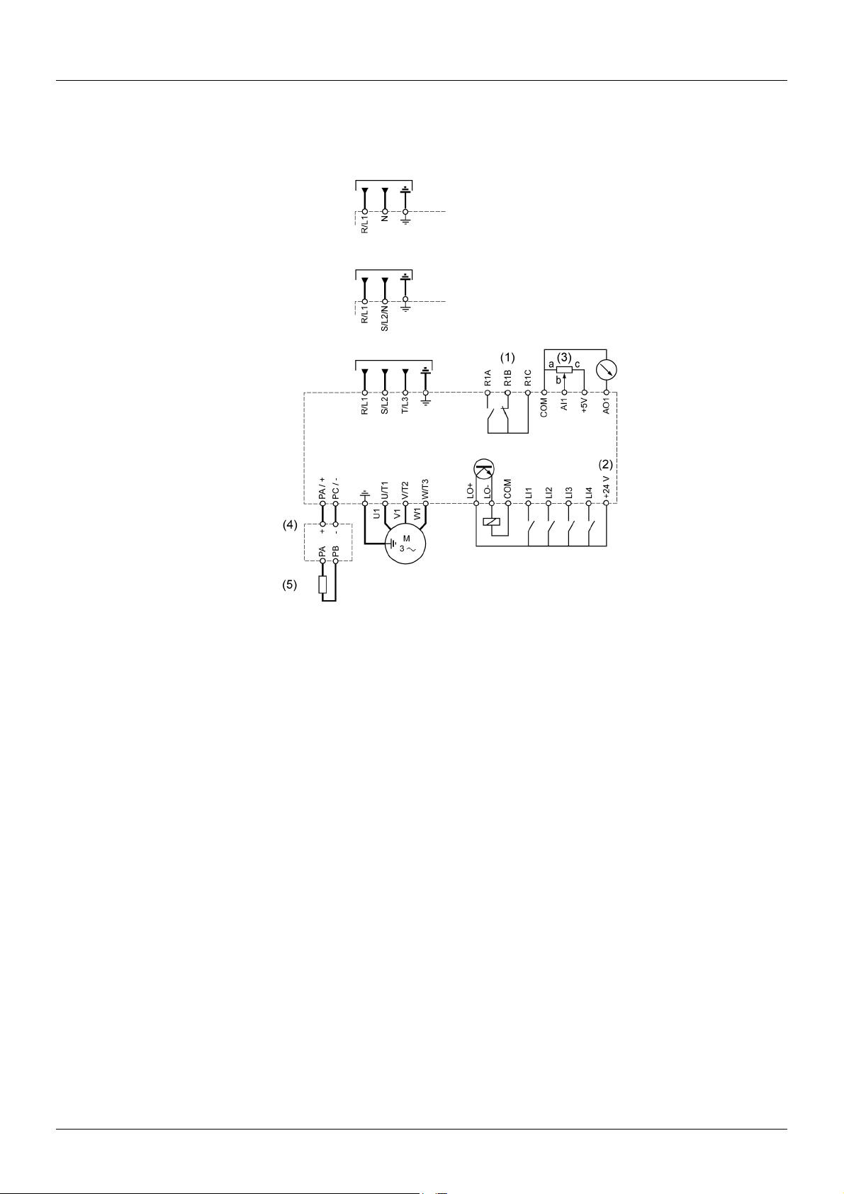
General wiring diagram
ATV12ppppF1
TV12ppppM2
TV12ppppM3
Single-phase supply 100...120 V
Single-phase supply 200...240 V
Three-phase supply 200...240 V
3-phase
motor
Source
(1) R1 relay contacts, for remote indication of the drive status.
(2) Internal + 24 V
use the + 24 V
(3) Reference potentiometer SZ1RV1202 (2.2 k
(4) Optional braking module VW3A7005
(5) Optional braking resistor VW3A7
Note:
• Use transient voltage surge suppressors for all inductive circuits near the drive or coupled to the same circuit (relays, contactors,
solenoid valves, etc).
• The ground terminal (green screw) is located on the opposite side in comparison with its position on the ATV11 (see wiring trap label).
c. If an external source is used (+ 30 V c maximum), connect the 0 V of the source to the COM terminal, and do not
c terminal on the drive.
Ω) or similar (10 kΩ maximum).
ppp or other acceptable resistor. See the possible resistor values in the catalog.
18 BBV28581 05/2010
Page 19
Wiring
Wiring labels
ATV12HpppF1
Input 120 V
Output 240 V
ATV12H
ATV12H
pppM2
Input 240 V
Output 240 V
pppM3
Input 240 V
Output 240 V
BBV28581 05/2010 19
Page 20
Power terminals
Line supply is at the top of the drive, the motor power supply is at the bottom of the drive. The power terminals can be accessed without
opening the wiring trap if you use stripped wire cables.
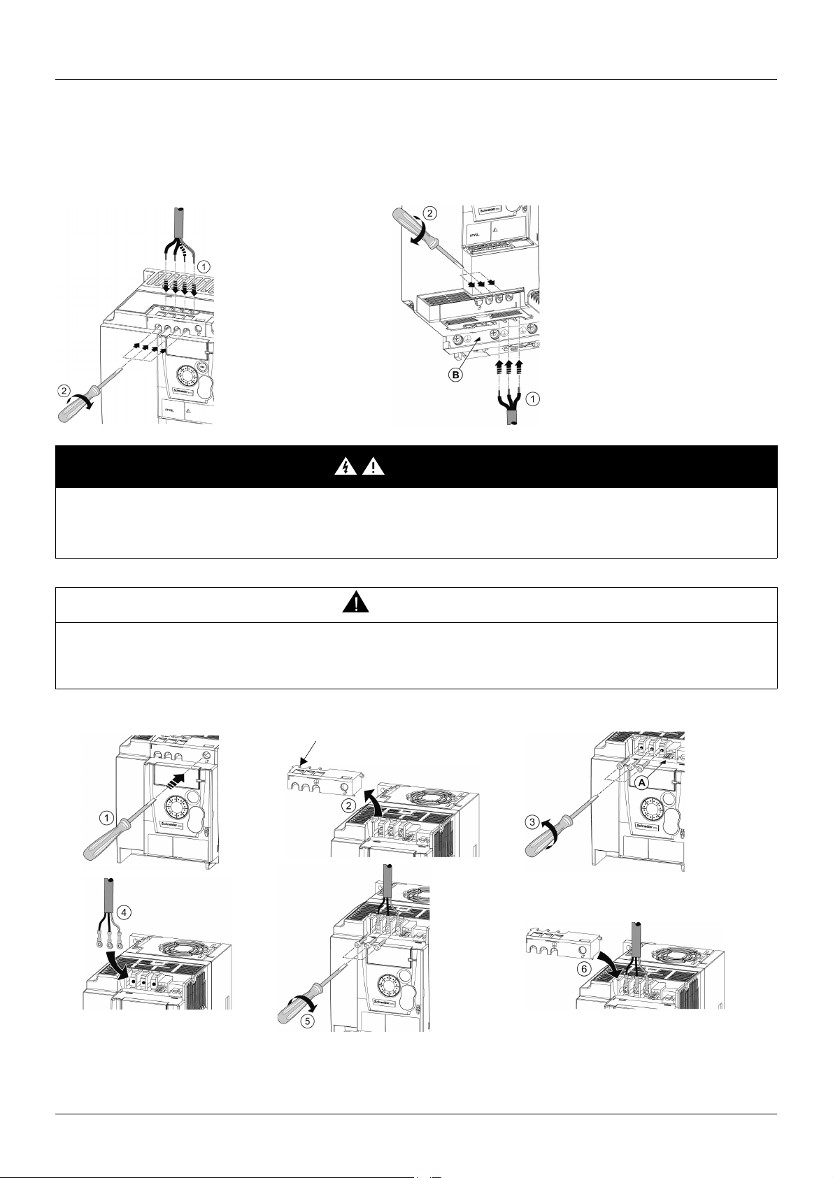
Access to the power terminals
Access to the terminals if you use stripped wire cables
DANGER
HAZARD OF ELECTRIC SHOCK, EXPLOSION, OR ARC FLASH
Replace the wiring trap before applying power.
Failure to follow these instructions will result in death or serious injury.
CAUTION
RISK OF BODY INJURY
Use pliers to remove snap-off of the wiring trap.
Failure to follow these instructions can result in injury or equipment damage.
Access to the line supply terminals to connect ring terminals
Wiring trap
A) IT jumper on ATV12ppppM2
B) Grounding screws located below the output terminals.
20 BBV28581 05/2010
Page 21
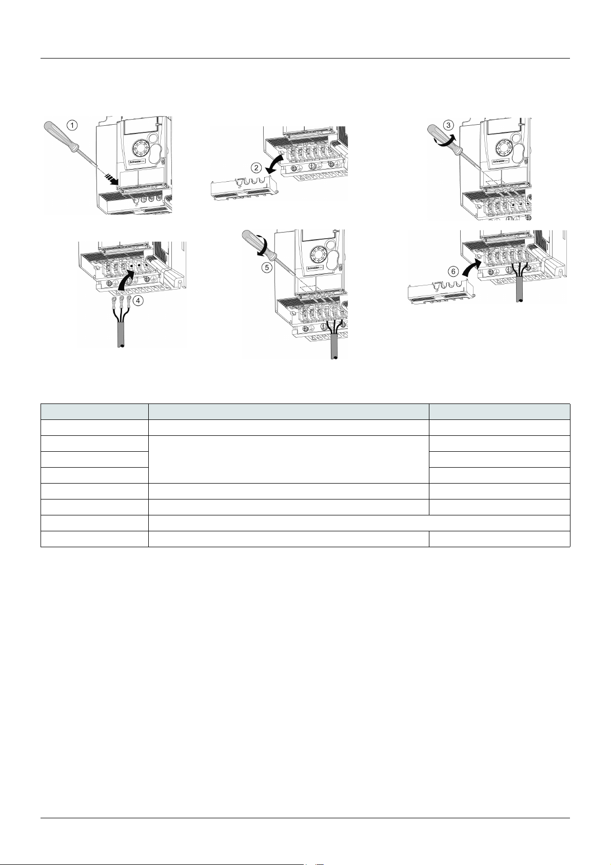
Power terminals
Access to the motor terminals if you use ring terminals
Characteristics and functions of power terminals
Terminal Function For ATV12
t
R/L1 - S/L2/N Power supply 1-phase 100…120 V
R/L1 - S/L2/N 1-phase 200…240 V
R/L1 - S/L2 - T/L3 3-phase 200…240 V
PA/+ + output (dc) to the braking module DC Bus (visible part on wiring trap) All ratings
PC/- – output (dc) to the braking module DC Bus (visible part on wiring trap) All ratings
PO Not used
U/T1 - V/T2 - W/T3 Outputs to the motor All ratings
Ground terminal All ratings
BBV28581 05/2010 21
Page 22
Power terminals
A
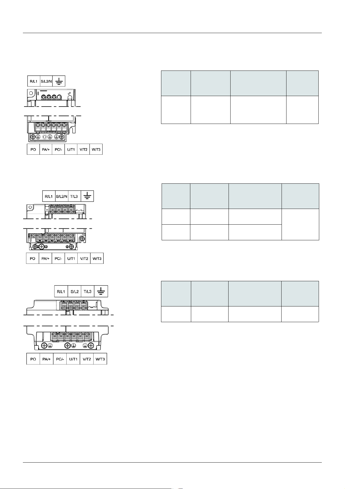
Arrangement of the power terminals
ATV12H 018F1, 037F1, 0ppM2, 0ppM3
ATV12H 075F1, U
ppM2, U15M3, U22M3
ATV12H
018F1
037F1
0
ppM2
0
ppM3
ATV12H
075F1
ppM2
U
U15M3
U22M3
Applicable wire
size (1)
mm² (AWG) mm² (AWG) N·m (lb.in)
2 to 3.5
(14 to 12)
Applicable
wire size (1)
mm² (AWG) mm² (AWG) N·m (lb.in)
3.5 to 5.5
(12 to 10)
2 to 5.5
(14 to 10)
Recommended
wire size (2)
2
(14)
Recommended
wire size (2)
5.5
(10)
2 (14) for U15M3
3.5 (12) for U22M3
Tightening
torque (3)
0.8 to 1
(7.1 to 8.9)
Tightening
torque (3)
1.2 to 1.4
(10.6 to 12.4)
TV12H U30M3, U40M3
ATV12H
U30M3
U40M3
(1)The value in bold corresponds to the minimum wire gauge to permit secureness.
(2)75°C (167 °F) copper cable (minimum wire size for rated use)
(3)Recommended to maximum value.
Applicable
wire size (1)
mm² (AWG) mm² (AWG) N·m (lb.in)
5.5 (10) 5.5 (10)
Recommended
wire size (2)
Tightening
torque (3)
1.2 to 1.4
(10.6 to 12.4)
22 BBV28581 05/2010
Page 23
Control terminals
Keep the control circuits away from the power cables. For control and speed reference circuits, we recommend using shielded twisted
cables with a pitch of between 25 and 50 mm (1 and 2 in.), connecting the shielding as outlined on page 26
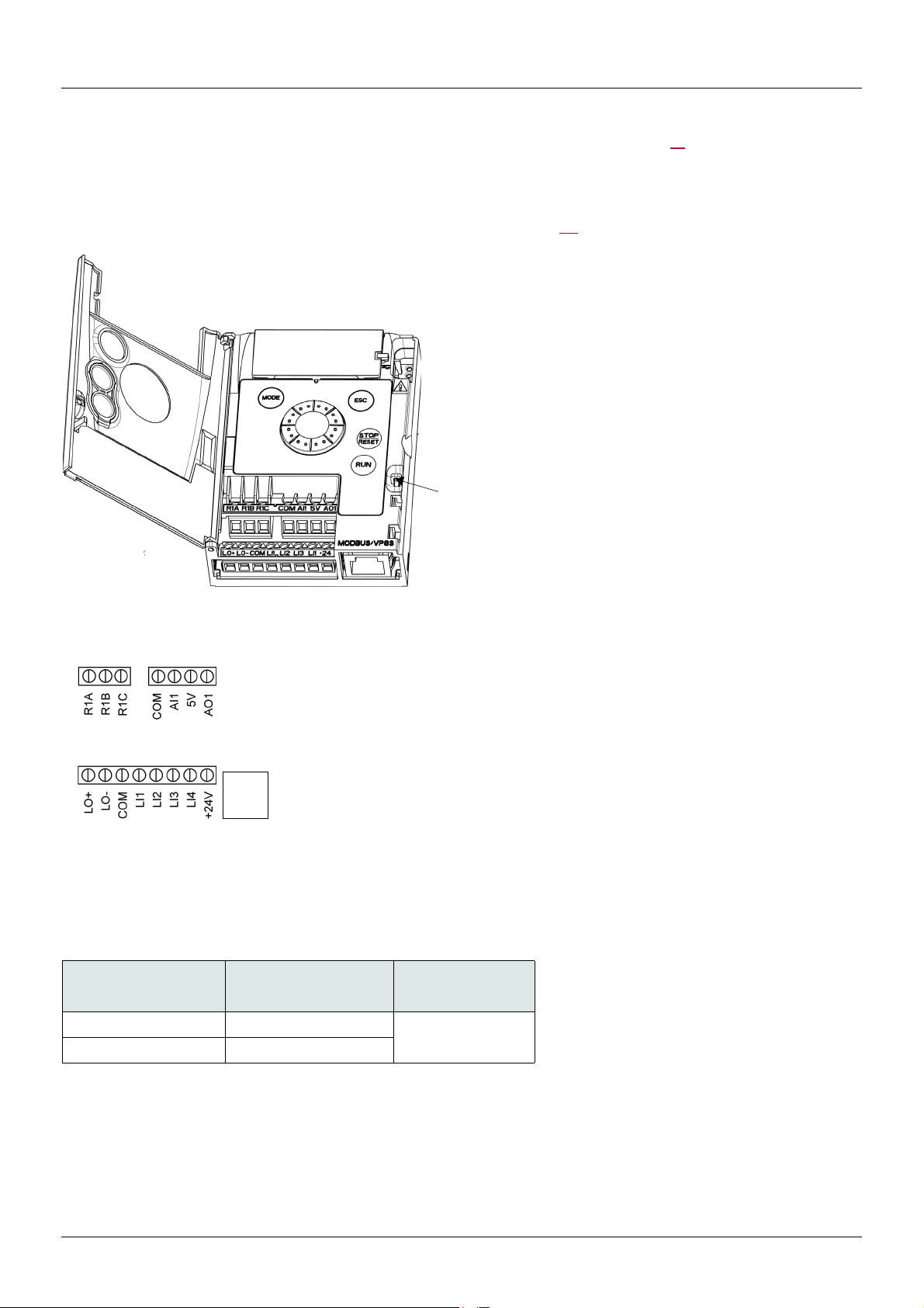
Access to the control terminals
To access the control terminals, open the cover.
Note: For information regarding HMI button functions, see "HMI description" on page 32.
It is possible to lock the
cover with a lead seal.
.
Arrangement of the control terminals
R1A
R1B
R1C
COM
AI1
5V
AO1
RJ45
Note: To connect cables, use a
slotted screwdriver 0.6 x 3.5.
ATV12 Control terminals Applicable wire size (1) Tightening torque (2)
R1A, R1B, R1C 0.75 to 1.5 (18 to 16)
Other terminals 0.14 to 1.5 (26 to 16)
LO+
LOCOM
LI1
LI2
LI3
LI4
+24V
RJ45
mm² (AWG) N·m (lb.in)
Normally open (NO) contact of the relay
Normally closed (NC) contact of the relay
Common pin of the relay
COMmon of analog and logic I/Os
Analog Input
+5VDC supply provided by the drive
Analog Output
Logic Output (collector)
Common of the Logic Output (emitter)
COMmon of analog and logic I/Os
Logic Input
Logic Input
Logic Input
Logic Input
+24 VDC supply provided by the drive
Connection for SoMove software, Modbus network or remote display.
0.5 to 0.6 (4.4 to 5.3)
(1)The value in bold corresponds to the minimum wire gauge to permit secureness.
(2)Recommended to maximum value.
BBV28581 05/2010 23
Page 24

Control terminals
Characteristics and functions of the control terminals
Terminal Function Electrical characteristics
R1A NO contact of the relay Min. switching capacity:
• 5 mA for 24 V
R1B NC contact of the relay
R1C Common pin of the relay
COM Common of analog and logic I/Os
AI1 Voltage or current analog input • resolution: 10 bits
5V +5 VDC power supply for reference potentiometer • precision: ± 5%
AO1 Voltage or current analog output (collector) • resolution: 8 bits
LO+ Logic output • voltage: 24 V (maximum 30 V)
LO- Common of the logic output (emitter)
LI1
LI2
LI3
LI4
+24V + 24 VDC supply provided by the drive + 24 VDC -15% +20% protected against short-circuits and
Logic inputs Programmable logic inputs
Maximum switching capacity:
• 2 A for 250 V
(cos ϕ = 0.4 and L/R = 7 ms)
• 3 A for 250 V
(cos ϕ = 1 and L/R = 0)
• response time: 30 ms maximum.
• precision: ± 1% at 25°C (77°F)
• linearity: ± 0.3% (of full scale)
• sampling time: 20 ms ± 1 ms
Analog voltage input 0 to +5 V or 0 to +10 V
(maximum voltage 30 V) impedance: 30 kΩ
Analog current input x to y mA, impedance: 250 Ω
• maximum current: 10 mA
• precision: ± 1% at 25°C (77°F)
• linearity: ± 0.3% (of full scale)
• refresh time: 4 ms (maximum 7 ms)
Analog voltage output: 0 to +10 V (maximum voltage +1%)
• minimum output impedance: 470 Ω
Analog current output: x to 20 mA
• maximum output impedance: 800 Ω
• impedance: 1 kΩ, maximum 10 mA (100 mA in open collector)
• linearity: ± 1%
• refresh time: 20 ms ± 1 ms.
• +24 VDC power supply (maximum 30 V)
• impedance: 3.5 kΩ
• state: 0 if < 5 V, state 1 if > 11 V in positive logic
• state: 1 if < 10 V, state 0 if > 16 V or switched off (not connected)
in negative logic
• sampling time: < 20 ms ± 1 ms.
overloads.
Maximum customer current available 100 mA
c
a and for 30 V c on inductive load
a and 4 A for 30 V c on resistive load
24 BBV28581 05/2010
Page 25
Control terminals
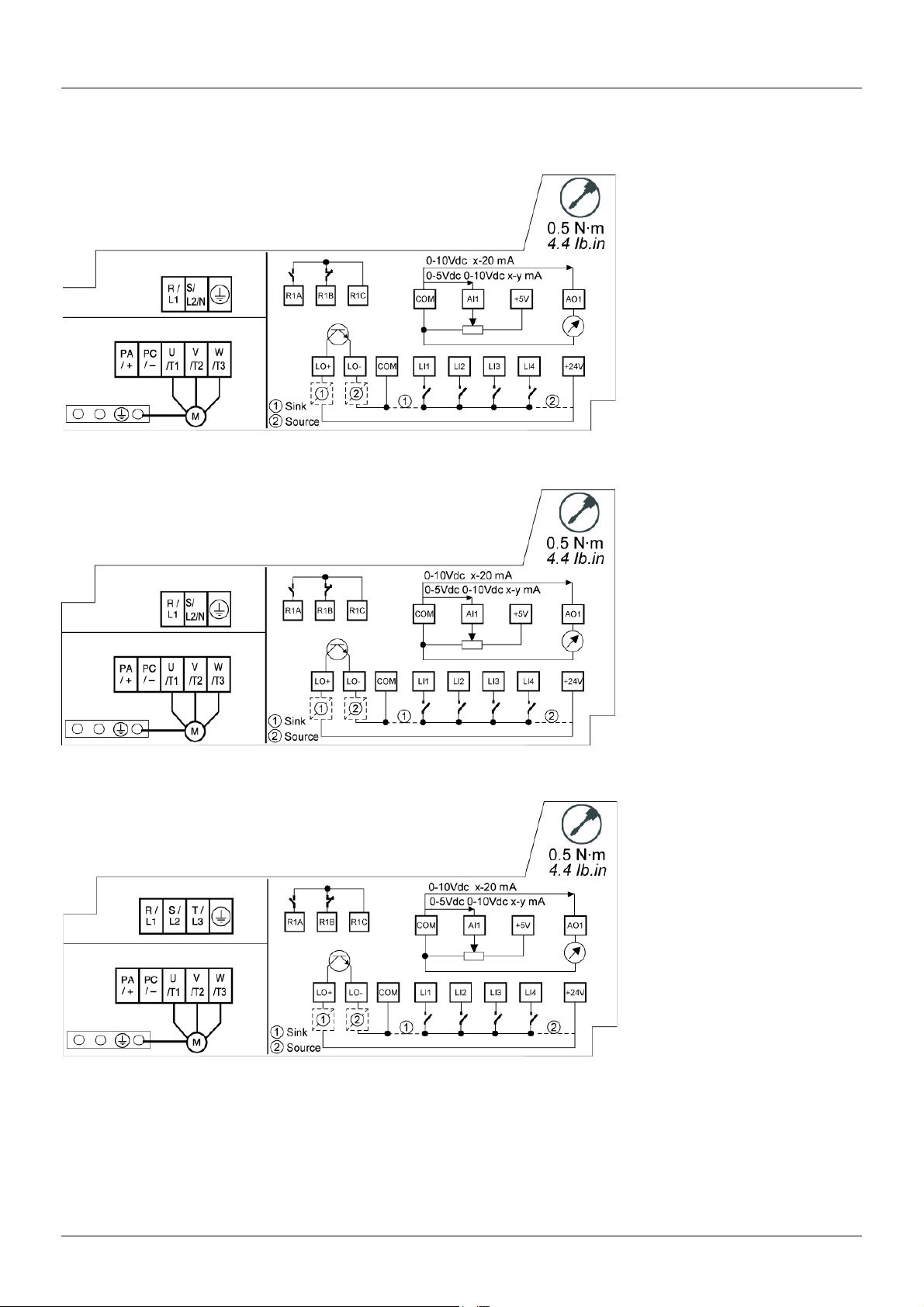
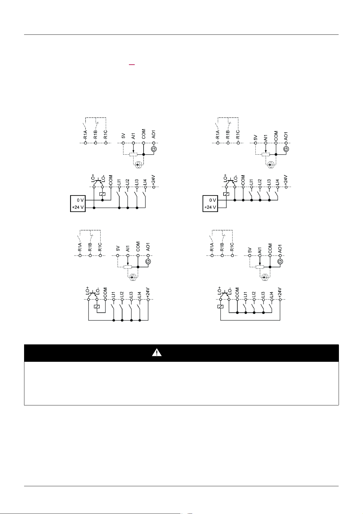
Control connection diagrams
The Logic inputs type nPL parameter page 51 is used to adapt the operation of the logic inputs to the technology of the programmable
controller outputs.
• Set the parameter to POS for Source operation.
• Set the parameter to nEG for internal Sink operation.
• Set the parameter to EnEG for external Sink operation.
Note: The modification will be taken into account only at the next control power on.
Source - using external supply Sink - using external supply
Source - using internal supply Sink - using internal supply
DANGER
UNINTENDED EQUIPMENT OPERATION
• The accidental grounding of logic inputs configured for Sink Logic can result in unintended activation of drive functions.
• Protect the signal conductors against damage that could result in unintentional conductor grounding.
• Follow NFPA 79 and EN 60204 guidelines for proper control circuit grounding practices.
Failure to follow these instructions will result in death or serious injury.
BBV28581 05/2010 25
Page 26

Wiring
Electromagnetic compatibility (EMC)
Note: The high frequency equipotential ground connection between the drive, motor, and cable shielding does not eliminate the need to
connect the ground (PE) conductors (green-yellow) to the appropriate terminals on each unit. See Wiring recommendations on page 16
Principle and precautions
• Grounds between the drive, motor, and cable shielding must have high frequency equipotentiality.
• When using shielded cable for the motor, use a 4-conductor cable so that one wire will be the ground connection between the motor
and the drive. The size of the ground conductor must be selected in compliance with local and national codes. The shield can then
be grounded at both ends. Metal ducting or conduit can be used for part or all of the shielding length, provided there is no break in
continuity.
• When using shielded cable for Dynamic Brake (DB) resistors, use a 3-conductor cable so that one wire will be the ground connection
between the DB resistor assembly and the drive. The size of the ground conductor must be selected in compliance with local and
national codes. The shield can then be grounded at both ends. Metal ducting or conduit can be used for part or all of the shielding
length, provided there is no break in continuity.
• When using shielded cable for control signals, if the cable is connecting equipment that is close together and the grounds are bonded
together, then both ends of the shield can be grounded. If the cable is connected to equipment that may have a different ground
potential, then ground the shield at one end only to prevent large currents from flowing in the shield. The shield on the ungrounded
end may be tied to ground with a capacitor (for example: 10 nF, 100 V or higher) in order to provide a path for the higher frequency
noise. Keep the control circuits away from the power circuits. For control and speed reference circuits, we recommend using shielded
twisted cables with a pitch of between 25 and 50 mm (0.98 and 1.97 in.) Keep the control circuits away from the power circuits. For
control and speed reference circuits, we recommend using shielded twisted cables with a pitch of between 25 and 50 mm (0.98 and
1.97 in.)
.
• Ensure maximum separation between the power supply cable (line supply) and the motor cable.
• The motor cables must be at least 0.5 m (20 in.) long.
• Do not use surge arresters or power factor correction capacitors on the variable speed drive output.
• If using an additional input filter, it should be mounted as closed as possible to the drive and connected directly to the line supply via
an unshielded cable. Link 1 on the drive is via the filter output cable.
• For installation of the optional EMC plate and instructions for meeting IEC 61800-3 standard, refer to the section entitled “Installing
the EMC plates” and the instructions provided with the EMC plates.
DANGER
HAZARD OF ELECTRIC SHOCK, EXPLOSION OR ARC FLASH
• Do not expose cable shielding except where connected to ground at the metal cable glands and underneath the grounding clamps.
• Ensure that there is no risk of the shielding coming into contact with live components.
Failure to follow these instructions will result in death or serious injury.
26 BBV28581 05/2010
Page 27
Wiring
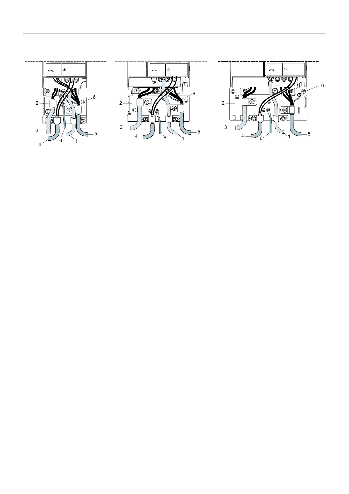
Installation diagram (example)
1. Non-shielded wires for the output of the status relay contacts.
2. Sheet steel grounded casing not supplied with the drive, to be mounted as indicated on the diagram.
3. PA and PC terminals, to the braking module DC bus
4. Shielded cable for connecting the control/signalling wiring.
For applications requiring several conductors, use small cross-sections (0.5 mm
The shielding must be connected to ground at both ends. The shielding must be continuous and intermediate terminals must be in EMC
shielded metal boxes.
5. Shielded cable for motor connection with shielding connected to ground at both ends.
This shielding must be continuous, and if there are any intermediate terminals, these must be in an EMC shielded metal box. The motor
cable PE grounding conductor (green-yellow) must be connected to the grounded casing.
6. Grounding conductor, cross-section 10 mm² (6 AWG) according to IEC 61800-5-1 standard.
7. Power input (non shielded cable)
Attach and ground the shielding of cables 4 and 5 as close as possible to the drive:
• Expose the shielding.
• Use cable clamps of an appropriate size on the parts from which the shielding has been exposed, to attach them to the casing.
The shielding must be clamped tightly enough to the metal plate to ensure correct contact.
• Types of clamp: stainless steel (delivered with the optional EMC plate).
2
, 20 AWG).
BBV28581 05/2010 27
Page 28
Wiring
EMC conditions for ATV12ppppM2
C1 EMC category is reached if length of shielded cable is 5 m (16.4 ft) maximum and Switching frequency SFr page 59 is 4, 8 or 12 kHz.
C2 EMC category is reached if length of shielded cable is 10 m (32.8 ft) maximum and Switching frequency SFr is 4, 8 or 12 kHz and if
length of shielded cable is 5 m (16.4 ft) maximum for all other values of Switching frequency SFr.
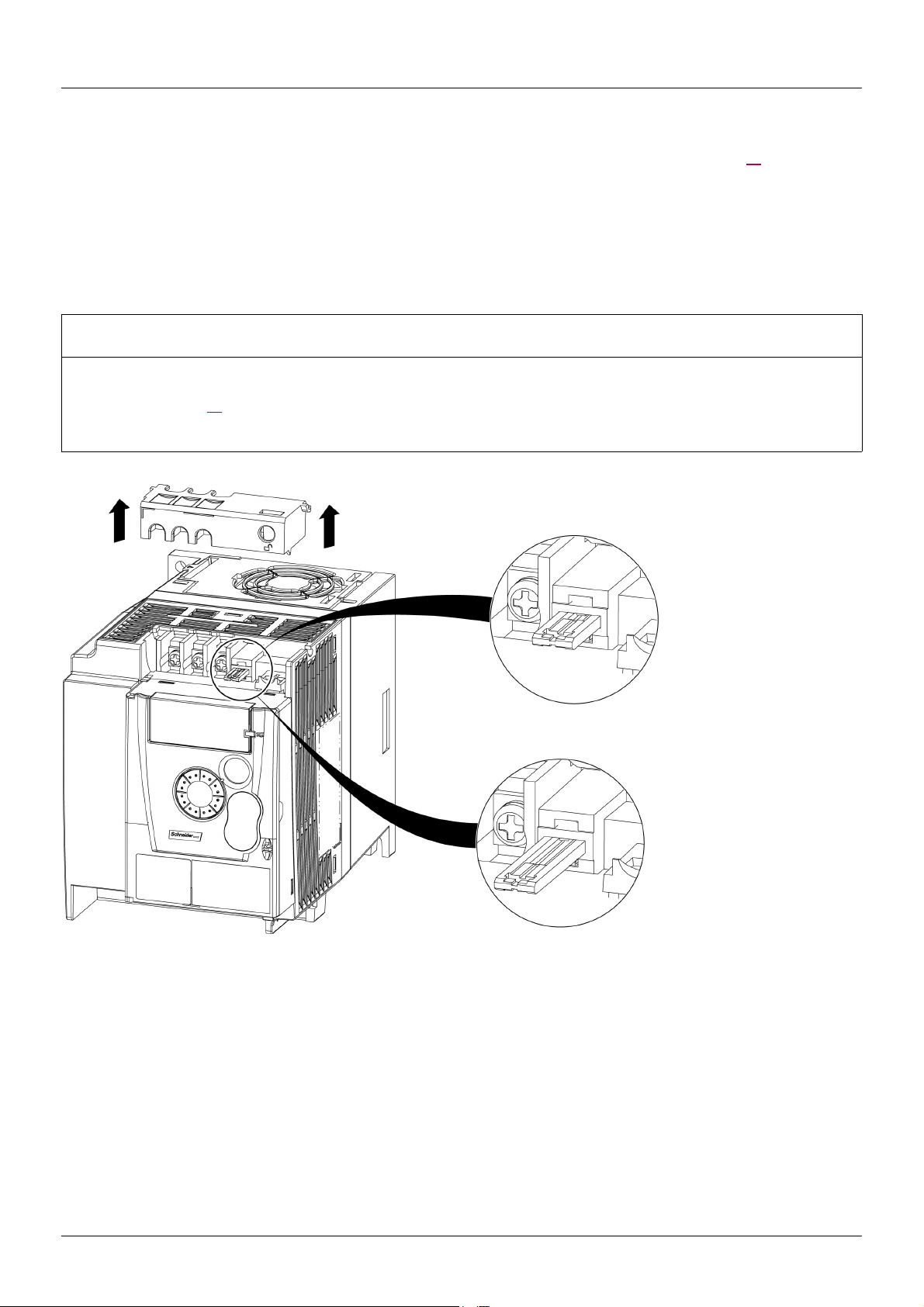
Internal EMC filter on ATV12ppppM2
All ATV12ppppM2 drives have a built-in EMC filter. As a result they exhibit leakage current to ground. If the leakage current creates
compatibility problems with your installation (residual current device or other), then you can reduce the leakage current by opening the IT
jumper as shown below. In this configuration EMC compliance is not guaranteed.
CAUTION
DRIVE LIFETIME REDUCTION
On ATV12ppppM2 ratings, if the filters are disconnected, the drive’s switching frequency must not exceed 4 kHz. Refer to Switching
frequency SFr page 59
Failure to follow these instructions can result in equipment damage.
for adjustment,
Normal
(filter connected)
IT system
(filter disconnected)
28 BBV28581 05/2010
Page 29

Check list
Read carefully the safety information in the user manual and the catalogue. Before starting up the drive, please check the following points
regarding mechanical and electrical installations, then use and run the drive.
For complete documentation, refer to www.schneider-electric.com.
1. Mechanical installation
• For drive mounting types and recommendations on the ambient temperature, please refer to the Mounting and temperature conditions
instructions on page 13
.
• Mount the drive vertically as specified, see Mounting and temperature conditions instructions on page 13
• The use of the drive must be in agreement with the environments defined by the standard 60721-3-3 and according to the levels
defined in the catalogue.
• Mount the options required for your application, refer to the catalogue.
.
2. Electrical installation
• Connect the drive to the ground, see Equipment grounding on page 16.
• Ensure that the input power voltage corresponds to the drive nominal voltage and connect the line supply as shown in General wiring
diagram on page 18
• Ensure you use appropriate input power fuses and circuit breaker on page 121
• Wire the control terminals as required, see Control terminals on page 23. Separate the power cable and the control cable according
to the EMC compatibility rules on page 26
• The ATV12ppppM2 range integrates an EMC filter. The leakage current can be reduced using the IT jumper as explained in the
paragraph Internal EMC filter on ATV12ppppM2 on page 28
• Ensure that motor connections correspond to the voltage (star, delta).
.
.
.
3. Use and run the drive
• Start the drive and you will see Standard motor frequency bFr page 45 at the first power on. Check that the frequency defined by
the frequency bFr (the factory setting is 50 Hz) is in accordance with the frequency of the motor, see First power-up on page 34
For the following power on, you will see rdY on the HMI.
.
• MyMenu (upper part of CONF mode) allows you to configure the drive for most applications (see page 45
• Factory / recall customer parameter set FCS function page 46
allows you to reset the drive with factory settings.
).
BBV28581 05/2010 29
Page 30
Factory configuration
Drive factory settings
The Altivar 12 is factory-set for the most common operating conditions (motor rating according to drive rating):
• Display: drive ready (rdY) motor stopped or motor frequency reference while running
• Automatic adaptation of the deceleration ramp in the event of overvoltage on braking.
• No automatic restarting after a detected fault is cleared
• Logic inputs:
- LI1: forward (2-wire transitional control)
- LI2, LI3, LI4: no assignment
• Logic output: LO1: no assignment
• Analog input: AI1 (0 to + 5 V) speed reference
• Relay R1: the contact opens in the event of a detected fault (or drive off)
• Analog output AO1: no assignment
Code Description Value
bFr Standard motor frequency 50 Hz
UnS Rated motor voltage 230 V
ACC Acceleration 3 seconds
dEC Deceleration 3 seconds
LSP Low speed 0 Hz
HSP High speed 50 Hz
Ctt Motor control type Standard U/F law
UFr IR compensation (law U/F) 100%
Ith Motor thermal current equal to nominal motor current (value determined by drive rating)
SdC1 Automatic DC injection current 0.7 x nominal drive current, for 0.5 seconds.
SFr Switching frequency 4 kHz
If the above values are compatible with the application, the drive can be used without changing the settings.
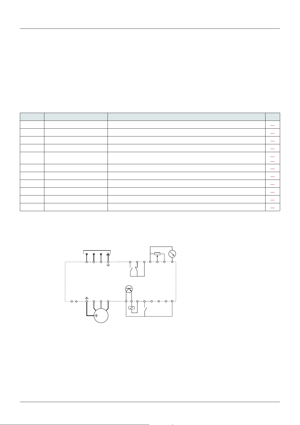
Drive factory wiring diagram
ATV12ppppM3
R/L1
S/L2
(1) (3)
R1A
T/L3
R1B
ac
b
R1C
COM
AI1
+5V
AO1
page
45
57
64
64
45
89
90
57
58
94
67
59
PA / +
PC / -
U/T1
V/T2
V1
U1
M
3 a
3-phase
W1
W/T3
LO+
LO-
(4)
COM
Source
LI1
LI2
LI3
LI4
(2)
+24 V
motor
(1) R1 relay contacts, for remote indication of the drive status.
(2) Internal + 24 V
use the + 24 V
(3) Reference potentiometer SZ1RV1202 (2.2 k
c. If an external source is used (+ 30 V c maximum), connect the 0 V of the source to the COM terminal, and do not
c terminal on the drive.
Ω) or similar (10 kΩ maximum).
(4) Forward
30 BBV28581 05/2010
Page 31

Basic functions
Status relay, unlocking
The R1 status relay is energized when the drive power is applied with no fault detected. It de-energizes in the event of a detected fault or
when the drive power is removed.
The drive is reset after a detected fault:
• by switching off the drive until the display disappears completely, then switching on again
• automatically in the cases described in the "automatic restart" function, FLt- menu, Automatic restart Atr page 91
• via a logic input when this input is assigned to the "drive reset" function, FLt- menu, Detected fault reset assignment rSF page
91
set to LpH.
Drive thermal detection
Thermal detection is provided by a built-in PTC probe in the power module.
Drive ventilation
Ratings up to 0.75 kW (1 HP) do not include a fan. The fan runs only when the drive thermal state requires ventilation.
Motor thermal detection
Function:
Thermal detection by calculating the I2t.
set to YES
Note: The motor thermal state memory returns to zero when the drive power is cycled if Motor thermal state memo MtM page 94
is not set to YES.
CAUTION
RISK OF DAMAGE TO THE MOTOR
The use of external overload protection is required under the following conditions:
• Repowering up the product since there is no motor thermal state memory.
• Running multiple motors
• Running motors rated at less than 20% of the nominal drive current
• Using motor switching
Failure to follow these instructions can result in equipment damage.
CAUTION
MOTOR OVERHEATING
• This drive does not provide direct thermal protection for the motor.
• Use of a thermal sensor in the motor may be required for protection at all speeds or loading conditions.
• Consult the motor manufacturer for the thermal capability of the motor when operated over the desired speed range
Failure to follow these instructions can result in equipment damage.
BBV28581 05/2010 31
Page 32

Programming
HMI description
Functions of the display and keys
1. Value LED (a) (b).
2. Charge LED
3. Unit LED (c)
4. ESC button: Exits a menu or parameter, or aborts the displayed
value to return to the previous value in the memory. In LOCAL
configuration, 2 s press on ESC button switches between the
control/programming modes.
5. STOP button: stops the motor (could be hidden by door if function
disabled). Note: See instructions for "RUN/STOP" cover
removal.
6. RUN button: Starts running in LOCAL configuration and in REMOTE configuration if the function is configured (could be hidden by door if function disabled).
7. Jog dial
- Acts as a potentiometer in LOCAL configuration and in
REMOTE configuration if the function is configured.
- For navigation when turned clockwise or counterclockwise
- and selection / validation when pushed.
This action is represented by this symbol
8. MODE button
Switches between the control/programming modes. 3s press on
MODE button switches between the REMOTE/LOCAL
configurations.
The MODE button is only accessible with the HMI door open.
9. CONFIGURATION mode LED (b)
10. MONITORING mode LED
11. REFERENCE mode LED
12. Four "7-segment" displays
Note: In LOCAL configuration, the three Leds 9, 10, 11 are blinking
simultaneously in programming mode and are working as a Led
chaser in control mode.
(a) If illuminated, indicates that a value is displayed, for example,
(b)When changing a value the Configuration mode LED and the value LED are on steady.
(c) If illuminated, indicates that a unit is displayed, for example, AMP is displayed for "Amps"
5 is displayed for "0.5"0.
32 BBV28581 05/2010
Page 33

Programming
Remote control
Remote operation and programming by HMI is possible using the optional remote HMI part VW3A1006. The dimensions are 70 mm
(2.76 in) x 50 mm (2.76 in).
Note: when connected, the remote control shows an exact copy of the drive display, it is totally interactive with the embedded keypad.
Note: Set the remote keypad with
- Modbus rate = 19.2 Kbps, (see tbr)
- Modbus format = 8E1, 8 bit, even parity, 1 stop bit (see tFO)
BBV28581 05/2010 33
Page 34

Programming
First power-up
At first power-up you are prompted to set Standard motor frequency bFr page 45. Next time power is applied rdY appears. Operating
mode selection is then possible using the MODE key as detailed below.
Menus structure
Access to menus and parameters is possible through 3 modes: Reference rEF page 37, Monitoring MOn page 38 and Configuration
COnF page 44
the MODE key moves from the current position to the top of the branch. A second press switches to the next mode.
. Switching between these modes is possible at any time using the MODE key or Jog Dial on keyboard. The first press on
[REMOTE configuration]
MODE
3s
rEN
ESC
rEF
MODE MODE MODE
[SPEED REFERENCE] [MONITORING] [CONFIGURATION]
MODE
3s
[LOCAL configuration]
LOC
rdY
[Analog input virtual
(Hz)]
35.
ESC
2s
ESCESC
COnFMOn
rdY
ESC ENT
Menu customization using SoMove
ATV12 factory settings enable drive operation with most applications. You can use SoMove software to customize the "MyMenu" and FULL
menus of COnF mode (see page 44
configuration has been adjusted, it can be downloaded to the ATV12 by connecting the drive to the computer or by downloading the
configuration through the multiloader or simpleloader.
SoMove can be used to operate the drive for testing and commissioning.
), by selecting which menus and parameters will be hidden or accessible for the user. Once the
Description References
SoMove USB/RJ45 cable TCSMCNAM3M002P
Simple-loader tool VW3A8120
Multi-loader tool VW3A8121
Bluetooth adapter VW3A8114
For further information, please consult the SoMove help.
34 BBV28581 05/2010
Page 35
Structure of parameter tables
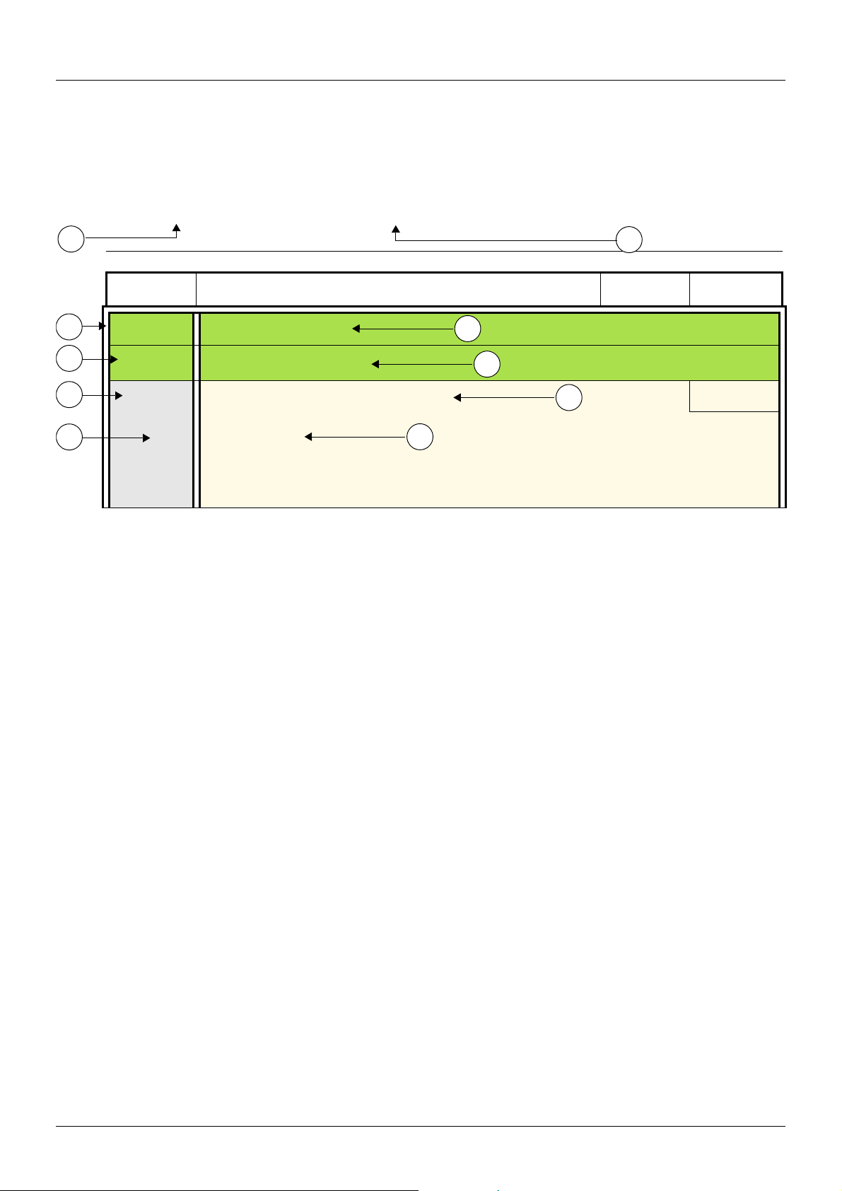
The modes, sections, menus, sub-menus and parameter tables description is organized as below.
Note: Parameters containing the sign
Example:
T in the code column can be modified with the drive running or stopped
Configuration Mode - Complete menu (FULL)
1
2
Code
3
4
5
6
1. Name of mode
2. Name of section, if any
3. Menu code on 4-digit display, followed by a "-"
4. Sub-menu code on 4-digit display, if any
5. Parameter code
FUn-
CtL-
FLO
LIH
L2H
L3H
L4H
Name / Description Adjustment
Function menu
Control menu
M Forced local assignment
nO
v No
v L1h
v L2h
v L3h
v L4h
range
7
8
9
10
6. Value code
7. Name of menu
8. Name of sub-menu
9. Parameter description
10. Possible value(s) / state of parameter, if any.
Factory
setting
nO
BBV28581 05/2010 35
Page 36

Function compatibility table
)
PI regulator (page 72
Preset speed (page 70)
Preset speed (page 70)
)
Auto DC injection (page 67
)
Catch on the fly (page 92
)
Fast stop (page 66
)
Freewheel (page 66
)
Jog operation (page 68
A
PI regulator (page 72
Jog operation (page 68
Auto DC injection (page 67
Catch on the fly (page 92
Fast stop (page 66
Freewheel (page 66
Incompatible functions Compatible functions Not applicable
Priority function (function which can be active at the same time)
The function indicated by the arrow has priority over the other.
Stop functions have priority over run commands.
Speed references via logic command have priority over analog references.
)
)
)
)
)
)
Xp
p
X
A
XAX
A
X
A
36 BBV28581 05/2010
Page 37

Reference Mode rEF
Use the reference mode to monitor and if local control is enabled (Reference channel 1 Fr1 page 45 set to AIU1) adjust the actual
reference value by rotating the jog dial.
When local control is enabled, the jog dial on the HMI acts as a potentiometer to change the reference value up and down within the limits
preset by other parameters (LSP or HSP). There is no need to press the ENT key to confirm the change of the reference.
If local command mode is disabled, using Command channel 1 Cd1 page 63
will be "read only" and cannot be modified by the jog dial (the reference is no longer given by the jog dial but from an AI or other source).
The actual reference displayed depends on the choice made in Reference channel 1 Fr1 page 62
Organization tree
, only reference values and units are displayed. The value
.
(1) Depending on the active reference channel
Possible values:
LFr
AIU1
FrH
rPI
rPC
(2) 2s or ESC
Displayed parameter value and unit of the
diagram is given as examples
Code
LFr
T
(1)
Name/Description Adjustment
M External reference value
Frequency reference visible if reference channel active is remote display.
Reference channel 1 Fr1 page 62
or Forced local reference FLOC page 63
This parameter allows to modify the frequency reference with the jog dial.
Visibility depends on the drive settings.
Value - Unit
Factory
range
-400 to +400 Hz -
set to LCC
set to LCC.
settings
AIU1
T
(1)
FrH
AI1
LCC
Mdb
AIUI
rPI
T
(1)
rPC
(1) It is not necessary to press the ENT key to confirm the modification of the reference.
T
Parameter that can be modified during operation or when stopped.
M Analog input virtual
This parameter allows to modify the frequency reference with an analog input.
Reference channel 1 Fr1 page 62
or Forced local reference FLOC page 63
or PID manual reference PIM page 74
Visibility depends on the drive settings.
M Speed reference
Actual frequency reference. This parameter is in read-only mode. Visibility depends on the drive settings.
v Terminal
v Remote display
v Modbus
v Integrated display with Jog dial
M Internal PID reference
This parameter allows to modify the PID internal reference with the jog dial.
Visibility depends on the drive settings.
M PID reference value
This parameter is the PID reference expressed as a %.
set to AIU1
set to AIU1
set to AIU1.
0 to 100 % of HSP -
0 Hz to HSP -
0 to 100% -
0 to 100% -
BBV28581 05/2010 37
Page 38

Monitoring mode MOn
When the drive is running, the value displayed is that of one of the monitoring parameters. The default value displayed is the motor Output
frequency rFr page 39
While the value of the desired new monitoring parameter is being displayed, press a second time on the jog dial button to display the units.
Organization tree
.
values
units
(1) Depending on reference channel active.
Possible values:
LFr
AIU1
(2) 2 sec or ESC
38 BBV28581 05/2010
Displayed parameter values and units of the diagram are given as
examples.
Page 39

Monitoring mode MOn
Code
LFr
T
AIU1
T
FrH
rFr
LCr
rPE
rPF
rPC
ULn
Name/Description Unit
M External reference value
External keypad or local force mode configured. Forced local reference FLOC page 63 set to LCC and
and Forced local assignment FLO page 63
Displays the speed reference coming from the remote keypad. This value is not visible in factory setting.
M Analog input virtual
Embedded keypad active or local force mode configured, Forced local reference FLOC page 63 set to
AIU1 and Forced local assignment FLO page 63
Displays the speed reference coming from the jog dial. This value is not visible in factory setting.
M Speed reference
Actual frequency reference.
M Output frequency
This function provides the estimated motor speed. It corresponds to the estimated motor frequency (on the
motor shaft). In Standard law Std page 57
In Performance law PErF page 57
motor speed.
Range: -400 to 400 Hz
M Motor current
Estimation of the effective motor current from phase current measurements with an accuracy of 5%.
During DC injection, the current displayed is the maximum value of current injected in the motor.
M PID error
Visible only if the PID function is configured (PID feedback assignment PIF page 72 set to nO).
See PID diagram on page 71
M PID Feedback
Visible only if PID function configured (PID feedback assignment PIF page 72 set to nO). See
PID diagram on page 71
M PID reference
Visible only if PID function configured (PID feedback assignment PIF page 72 set to nO). See
PID diagram on page 71
M Main voltage
Line voltage from the point of view of the DC bus, motor running or stopped.
different to nO.
different to nO.
, the Output frequency rFr is equal to stator frequency.
, the Output frequency rFr motor speed is equal to the estimated
Hz
%
Hz
Hz
A
%
%
%
V
tHr
tHd
Opr
T
BBV28581 05/2010 39
Parameter that can be modified during operation or when stopped.
M Motor thermal state
Display of the motor thermal state. Above 118%, the drive trips in Motor overload OLF page 109.
M Drive thermal state
Display of the drive thermal state. Above 118%, the drive trips in Drive overheat OHF page 109.
M Output power
This parameter displays the motor power (on the shaft) that is estimated by the drive.
%
%
%
Page 40

Monitoring mode MOn
Code
StAt
rdY
rUn
ACC
dEc
dCb
CLI
nSt
Obr
CtL
tUn
FSt
nLP
FrF
rEM
LOC
Name/Description
M Product status
This parameter shows the state of the drive and motor.
v Drive ready
v Drive running, the last six segments to the right of the code also indicate direction and speed.
v Acceleration, the last six segments to the right of the code also indicate direction and speed.
v Deceleration, the last six segments to the right of the code also indicate direction and speed.
v DC injection braking in progress
v Current limit, the four segments located on right down of display are blinking.
v Freewheel stop control
v Auto-adapted deceleration
v Controlled stop on mains phase loss
v Auto-tuning in progress
v Fast stop
v No line power. When the control part is energized via the RJ45 connector and there is no power on the
main input and no run order is present.
v Drive is running and using the withdrawal reference LFF
v Remote configuration
v Local configuration
40 BBV28581 05/2010
Page 41

Monitoring mode MOn
Code
MAI-
LIS1
LOS1
HSU
nCU
UCAL
SPn
C1SU
C2SU
Name/Description Unit
Maintenance menu
Parameters of MAI menu can’t be selected for monitoring
M State of logic inputs LI1 to LI4
Can be used to visualize the state of the 4 logic inputs LI.
State 1
State 0
LI1 LI2 LI3 LI4
Example above: LI1 and LI3 are at 1; LI2 and LI4 are at 0.
M State of the logic output LO1 and relay R1
Can be used to visualize the state of the LO.
State 1
State 0
r1 LO1
M Display of high speed value
Display of high speed value. Range Low speed LSP page 45 to Maximum frequency tFr page 57.
Visible only if 2 HSP assignment SH2 or 4 HSP assignment SH4 page 90
M Drive Power rating
Indicates the drive rating. This is part the of the drive reference, see page 11. Possible values:
018 = 0.18 kW (0.25 HP)
037 = 0.37 kW (0.50 HP)
055 = 0.55 kW (0.75 HP)
075 = 0.75 kW (1 HP)
U15 = 1.5 kW (2 HP)
U22 = 2.2 kW (3 HP)
U30 = 3 kW (3 HP)
U40 = 4 kW (5 HP)
M Drive voltage rating
Drive rate supply voltage. This is part the of the drive reference, see page 11. Possible values:
F1 = 100-120 V 1 phase in, 200-240 V 3 phase out
M2 = 200-240 V 1 phase in, 200-240 V 3 phase out
M3 = 200-240 V 3 phase in, 200-240 V 3 phase out
M Specific Product Number
This parameter is used in order to identify the possible specification of the product.
Visible only if SPn is different to zero.
M Card 1 Software Version
Application software version.
Example: 1105 for 1.1 ie 05.
1 (version, major). 1 (version, minor). 05 (ie, evolution number)
M Card 2 Software Version
Motor software version.
Example: 1105 for 1.1 ie 05.
1 (version, major). 1 (version, minor). 05 (ie, evolution number)
is configured.
-
-
Hz
-
-
-
-
-
BBV28581 05/2010 41
Page 42

Monitoring mode MOn
Code
MAI-
rtHI
PtH
FtH
PEt
T
Name/Description Unit
Maintenance menu (continued)
M Run elapsed time display
Total time the motor has been powered up. Range: 0 to 65535 hours. Value displayed is as described in the
table below. Parameter resettable by services
Hours Display
1 0.01
10 0.10
100 1.00
1000 10.0
10000 100
M Power On time display
Total time the drive has been powered on. Range: 0 to 65535 hours. Value displayed is as described in
the table above. Parameter resettable by services.
M Fan time display
Range: 0 to 65535 hours. Value displayed is as described in the table above. Parameter resettable by
customer.
M Process elapsed time
Range: 0 to 65535 hours. Value displayed is as described in the table above. Parameter resettable by
customer.
0.01
0.01
0.01
0.01
COM1
r0t0
rOt1
r1t0
r1t1
dP1
EP1
M Modbus communication status
v Modbus no reception, no transmission = communication idle
v Modbus no reception, transmission
v Modbus reception, no transmission
v Modbus reception and transmission
M Last detected fault 1
This parameter describes the last detected fault.
M State of drive at detected fault 1
This parameter describes the state at the moment of the 1st detected fault.
bit 0 bit 1 bit 2 bit 3 bit 4
ETA.1: Switched
on
bit 5 bit 6 bit 7 bit 8 bit 9
ETI.4: Run order
present
bit 10 bit 11 bit 12 bit 13 - 14 bit 15
ETI.10 : Product in
deceleration
ETA.5:
Quick stop
ETI.5:
DC injection
running
ETI.11 : Current
limitation or torque
limitation is
running
ETA.6:
Switch on
disabled
ETI.7:
Motor thermal
threshold reached
Fast stop in
progress
Forced local
enabled
ETI.8: Reserved ETI.9:
ETI.14= 0 + ETI.13=0 :
Drive controlled by terminal or local
ETI.14= 0 + ETI.13=1 :
Drive controlled by remote keypad
ETI.14= 1 + ETI.13=0 :
Drive controlled by Modbus
ETI.14= 1 + ETI.13=0 : Reserved
Motor rotation in forward direction
(or stopped)
Product in
acceleration
keypad
-
-
-
ETA.15 :
ETI.15 :
Reverse
direction
applied to the
ramp
T
42 BBV28581 05/2010
Parameter that can be modified during operation or when stopped.
Page 43

Monitoring mode MOn
Code
MAI-
dP2
EP2
dP3
EP3
dP4
EP4
COd
Name/Description Adjustment range Factory setting
Maintenance menu (continued)
M Last detected fault 2
This parameter describes the 2nd detected fault.
M State of drive at detected fault 2
This parameter describes the state at the moment of the 2nd detected fault. See EP1.
M Last detected fault 3
This parameter describes the 3rd detected fault.
M State of drive at detected fault 3
This parameter describes the state at the moment of the 3rd detected fault. See EP1
M Last detected fault 4
This parameter describes the 4th detected fault.
M State of drive at detected fault 4
This parameter describes the state at the moment of the 4th detected fault. See EP1
2 to 9999 OFF
OFF
On
M HMI Password
Possible state value:
v Code disabled
v Code activated
-
-
-
-
-
-
Range 2 to 9999
If you have lost your code, please contact Schneider Electric.
This parameter is used to restrict access to the drive.
To lock the drive, go to the HMI Password COd parameter, enter a code within the above range.
Once activated, the code state changes to On:
The protection enables only access to rEF(see page 37
using SoMove. Return to factory settings or access to FULL section are disabled,
Download configuration from SoMove is possible,
Upload configuration to SoMove is disabled.
To unlock the drive, go to the COd parameter, enter the valid code, then press ENT.
Code protection removal is then possible and carried out by entering OFF using the jog dial, then press
ENT.
) and MOn (see page 38) modes, except when
BBV28581 05/2010 43
Page 44

Configuration Mode ConF
Configuration mode includes 3 parts:
1. MyMenu includes 11 factory set parameters (among them 9 visible by default). Up to 25 parameters are available for user customization using SoMove software.
2. store/recall parameter set: these 2 functions are used to store and recall customer settings.
3. FULL: This menu provides access to all other parameters. It includes 6 sub-menus:
- Macro-configuration CFG- page 47
- Input Output menu I_O- page 48
- Motor control menu drC- page 58
- Control menu CtL- page 62
- Function menu FUn- page 64
- Fault detection management menu FLt- page 91
- Communication menu COM-page 97.
Organization tree
Motor frequency
Reference channel 1
Acceleration
Deceleration
Low speed
High speed
Motor rated power
Motor rated current
AI1 type
Store customer
parameter set
Factory / recall
customer parameter set
FULL
Displayed parameter values are given as examples only
(1) Depending on reference channel
active.
Possible values: LFr or AIU1
44 BBV28581 05/2010
(2) 2 seconds or ESC. (3) plus 14 other customizable parameters selectable (in "FULL" list)
using SoMove.
Page 45

Configuration Mode - MyMenu
Code
LFr
T
AIU1
T
bFr
Fr1
AI1
LCC
Mdb
AIUI
Name/Description Adjustment range Factory setting
-400 Hz to 400 Hz -
set to LCC and
0% to 100% -
50 Hz
AI1
50
60
M External reference value
This parameter allows to modify the frequency reference with the jog dial.
External keypad or local force mode configured. Forced local reference FLOC page 63
and Forced local assignment FLO page 63
M Analog input virtual
This parameter allows to modify the frequency reference when
• Forced local reference FLOC page 63
•and Forced local assignment FLO page 63
Visible if reference channel active is integrated display (Reference channel 1 Fr1 set to AIU1).
M Standard motor frequency
External keypad or local force mode configured (FLOC = LCC) (not visible in the factory setting).
v 50 Hz
v 60 Hz
Set to 50 Hz or 60 Hz, taken from the motor rating plate. Changing bFr sets back parameters:
FrS, Ftd and HSP: 50 Hz or 60 Hz
itH is set to nCr
nCr according to drive rating
nPr Watt or HP
nSP according to drive rating
tFr 60 Hz or 72 Hz
M Reference channel 1
This parameter allows selection of the reference source.
different to nO. Visibility depends on the drive settings.
is set to AIU1
is different to nO.
v Terminal
v Remote display
v Modbus
v Integrated display with Jog dial
ACC
T
dEC
T
LSP
T
HSP
T
M Acceleration
Acceleration time between 0 Hz and the Rated motor frequency FrS page 57.
Make sure that this value is compatible with the inertia being driven.
M Deceleration
Time to decelerate from the Rated motor frequency FrS page 57 to 0 Hz.
Make sure that this value is compatible with the inertia being driven.
M Low speed
Motor frequency at minimum reference
If HSP, HSP2, HSP3 and HSP4 are already set then LSP is limited to the minimum of those
values.
M High speed
Motor frequency at maximum reference.
Check that this setting is appropriate for the motor and the application. The values of HSP, HSP2,
HSP3 and HSP4 are idependent but each HSP value is linked to the values of Low speed LSP and
Maximum frequency tFr page 57
• HSPx is limited to LSP and tFr (LSP y HSPx y tFr).
•If tFr is decreased below the current HSPx value, then HSPx automatically decreases to the new
value of tFr.
• Once HSP, HSP2, HSP3 and HSP4 are set, LSP is limited to their minimum.
0.0 s to 999.9 s 3.0 s
0.0 s to 999.9 s 3.0 s
0 Hz to HSP 0 Hz
LSP to tFr (Hz) 50 or 60 Hz
according to BFr,
max TFr
according to the following rules:
T
BBV28581 05/2010 45
Parameter that can be modified during operation or when stopped.
Page 46

Configuration Mode - MyMenu
Code
nPr
SCS
Str1
2 s
FCS
rEC1
InI1
nO
nO
InI
Name/Description Adjustment range Factory setting
M Rated Motor Power
Visible only if Motor parameter choice MPC page 60 is set to nPr. If nPr is available CoS disappears.
Rated motor power given on the nameplate. Motors can range from five ratings lower up to two ratings
higher than the drive rating.. Performance is optimized when there is a maximum of one rating difference.
If Standard motor frequency bFr page 45
otherwise it will be HP.
M Store customer parameter set
This function creates a backup of the present configuration:
NCV -5 to
NCV +2
is set to 50Hz, the Rated motor power nPr unit will be kW,
According to drive
rating
nO
v Function inactive
v Saves the current configuration in the drive memory. SCS automatically switches to nO as soon as the
save has been performed.
When a drive leaves the factory the current configuration and the backup configuration are both initialized
with the factory configuration.
M Factory / recall customer parameter set
This function permits to restore a configuration.
nO
v Function inactive.
FCS automatically changes to nO as soon as one of the following actions has been performed.
v The current configuration becomes identical to the backup configuration previously saved by SCS.
FCS automatically changes to nO
if the backup has been carried out. If this value appears, InI1 is not visible.
as soon as this action has been performed. rEC1 is only visible
v The current configuration becomes identical to the factory setting. If this value appears, InI1 is not
visible.
v The current configuration becomes identical to the backup configuration previously defined by SoMove
software. If this value appears, Ini and rEC1 are not visible.
2 s
DANGER
UNINTENDED EQUIPMENT OPERATION
Check that the modification of the current configuration is compatible with the wiring diagram used.
Failure to follow these instructions will result in death or serious injury.
To change the assignment of this parameter press the “ENT” key for 2 s.
2 s
How to control the drive locally
In factory settings "RUN" and the jog dial are inactive. To control the drive locally, adjust the following parameter:
set Reference channel 1 Fr1 page 45
to AIU1 (Integrated display with jog dial).
LI assignment information
It is possible with ATV12 to use multi assignment function (ie: AC2 and rrS on the same LI).
It is also possible on some functions to assign LIH (high) or LIl (low), which means that the assigned function will be activated to high (LIH)
or low level (LIl) of LI.
46 BBV28581 05/2010
Page 47

Configuration Mode - Complete menu (FULL)
Code
CFG
2 s
StS
PId
SPd
Name/Description Adjustment range Factory setting
M Macro-configuration
StS
DANGER
UNINTENDED EQUIPMENT OPERATION
Check that the selected macro configuration is compatible with the wiring diagram used.
Failure to follow these instructions will result in death or serious injury.
Macro configuration provides a shortcut to configure a set of parameters suited to a specific field of
application.
3 macro configurations are available:
v Start/stop. Only forward is assigned
v PID regulation. Activate PID function, dedicated AI1 for feedback and AIV1 for reference.
v Speed. Allocate LI to preset speed (same allocation as ATV11) which provides a means of speeding up
the configuration of functions for a specific field of application.
Selecting a macro configuration assigns the parameters in this macro configuration.
Each macro configuration can still be modified in the other menus.
Input / output or parameter
AI1 Ref. channel 1 PID feedback No
AIV1 No Reference channel 1
AO1 No
LO1 No
R1 No drive detected fault
L1h (2-wire) Forward
L2h (2-wire) No Reverse
L3h (2-wire) No Auto/Manu 2 preset speeds
L4h (2-wire) No 4 preset speeds
L1h (3-wire) Stop
L2h (3-wire) Forward
L3h (3-wire) No Reverse
L4h (3-wire) No Auto / Manu 2 preset speeds
Fr1 (Reference channel 1)
Ctt (Motor control type)
rIn (Reverse inhibition)
AI1t (AI1t type)
LFLl (4-20 mA loss)
SP2 (Preset speed 2)
SP3 (Preset speed 3)
SP4 (Preset speed 4)
MPC (Motor parameter choice)
AdC (Automatic DC injection)
Start / Stop PID regulation Speed
AIUI AIUI
PUMP
YES
0A
YES
10.0
25.0
50.0
COS
YES YES YES
To change the assignment of this parameter press the “ENT” key for 2 s.
2 s
BBV28581 05/2010 47
Page 48

I-O-
drC-
CtL-
FUN-
FLt-
COM-
Configuration Mode - Complete menu (FULL)
Code
I_O-
tCC
Name/Description Adjustment range Factory setting
Input Output menu
M Type of control
2C
2 s
2C
3C
v 2-wire control (see page 51)
The open or closed state of the input controls the running or stopping.
Example of "source" wiring:
LI1: forward
LIx: reverse
v 3-wire control (see page 51)
"forward" or "reverse" pulse is sufficient to command starting, a "stop" pulse is sufficient to command
stopping
Example of "source" wiring:
LI1: stop
LI2: forward
LIx: reverse
DANGER
UNINTENDED EQUIPMENT OPERATION
When this parameter is changed, 2 wire type control tCt page 51 and all the assignments involving the logic
inputs will revert to their default values.
Check that this change is compatible with the wiring diagram used.
Failure to follow these instructions will result in death or serious injury.
To change the assignment of this parameter press the “ENT” key for 2 s.
2 s
48 BBV28581 05/2010
Page 49

Configuration Mode - Complete menu (FULL)
2 wire control diagrams (see page 51)
Drive powered and ready
2-Wire with transient detection
Drive
Speed
Forward
Reverse (1)
LI
Forward
LI
Reverse (1)
ready to start
I-O-
drC-
CtL-
FUN-
FLt-
COM-
t
t
t
2-Wire without transient detection
Speed
Forward
Reverse (1)
2-Wire without transient detection
Speed
Forward
Reverse (1)
(1) Reverse is not factory assigned. See Reverse direction rrS page 66
t
transient detection forward priority
t
.
Forward and Reverse realised in same time provides motor starting in Forward direction.
BBV28581 05/2010 49
Page 50
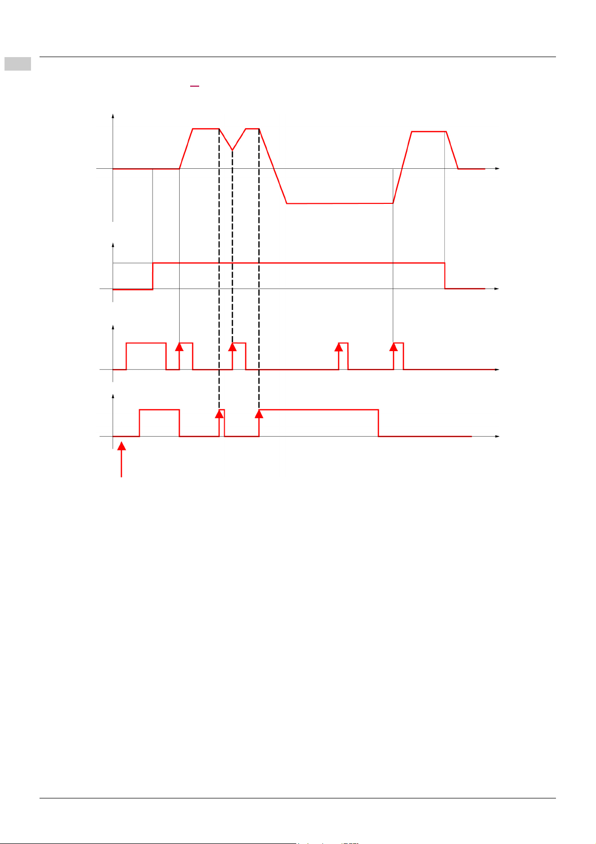
I-O-
drC-
CtL-
FUN-
FLt-
COM-
Configuration Mode - Complete menu (FULL)
3-wire control diagram (see page 51)
F: motor frequency
Reference
t
LI Run Enable
t
LI Forward
LI Reverse
t
t
Drive ready to respond to commands
50 BBV28581 05/2010
Page 51

Configuration Mode - Complete menu (FULL)
Code
I_O-
tCt
Name/Description Adjustment range Factory setting
Input Output menu (continued)
M 2 wire type control
DANGER
UNINTENDED EQUIPMENT OPERATION
Check that the modification of the 2 wire type control is compatible with the wiring diagram used.
Failure to follow these instructions will result in death or serious injury.
2-wire type control parameter can only be accessed if Type of control tCC page 48 is set to 2C.
trn
I-O-
drC-
CtL-
FUN-
FLt-
COM-
nPL
EnEG
LEL
trn
PFO
POS
nEG
v Level: State 0 or 1 is taken into account for run or stop.
v Transition: A change of state (transition or edge) is necessary to initiate operation, to help prevent
accidental restarts after a power supply interruption.
v Priority FW: State 0 or 1 is taken into account for run or stop, but the "forward" input takes priority over
the "reverse" input.
M Logic inputs type
POS
v Positive: the inputs are active (state 1) at a voltage equal to or higher than 11 V (for example +24 V
terminal). They are inactive (state 0) when the drive is disconnected or at a voltage lower than 5 V.
v Negative using internal supply: the inputs are active (state 1) at a voltage lower than 10 V (for example
COM terminal). They are inactive (state 0) at a voltage equal to or higher than 16 V or when the drive is
disconnected.
v Negative using external supply : the inputs are active (state 1) at a voltage lower than 10 V (for example
COM terminal). They are inactive (state 0) at a voltage equal to or higher than 16 V.
Note: The modification will be taken into account only at the next control power on.
See Control connection diagrams, page 25.
BBV28581 05/2010 51
Page 52

I-O-
drC-
CtL-
FUN-
FLt-
COM-
Configuration Mode - Complete menu (FULL)
Code
I_O-
AI1-
Name/Description Adjustment range Factory setting
Input Output menu (continued)
AI1 configuration menu
AI1t
CrL1
CrH1
I_O-
r1
5U
10U
0A
nO
FLt
rUn
FtA
FLA
CtA
SrA
tSA
ULA
OLA
AP1
M AI1 type
This function makes interface from the analog input signal to a drive internal value.
v Voltage: 0-5 Vdc
v Voltage: 0-10 Vdc
v Current: x-y mA. Range determined by the AI1 current scaling parameter of 0% CrL1 and AI1 current
scaling parameter of 100% CrH1 settings below, see page 52
M AI1 current scaling parameter of 0%
Visible only if AI1 type AI1t is set to 0A
M AI1 current scaling parameter of 100%
Visible only if AI1 type AI1t is set to 0A
Input Output menu (continued)
M R1 assignment
v Not assigned
v No error detected
v Drive run
v Frequency threshold reached
v HSP reached
v I threshold reached
v Frequency reference reached
v Motor thermal reached
v Underload alarm
v Overload alarm
v AI1 Al. 4-20 - Visible only if AI1t is set to 0A (see above)
5U
.
0 to 20 mA 4 mA
0 to 20 mA 20 mA
FLt
52 BBV28581 05/2010
Page 53

Configuration Mode - Complete menu (FULL)
Code
I_O-
LO1-
Name/Description Adjustment range Factory setting
Input Output menu (continued)
LO1 Configuration menu (LO1-)
I-O-
drC-
CtL-
FUN-
FLt-
COM-
LO1
LO1S
T
M LO1 assignment
Allows to adapt the logic output to the application need.
Same values as r1.
When MdE = YES, output LO1 is forced to PMP (See page 78
See previous page.
M LO1 status (output active level)
WARNING
LOSS OF CONTROL
When LO1S = nEG and LO1 is set to FLt, The output will be active when the drive will detect a fault.
The drive status will not be detected if the wiring is damaged for any reason.
Do not select "nEG" unless you are sure that your signal will be present in any case.
Failure to follow these instructions can result in death, serious injury, or equipment damage.
POS
nEG
Parameter that can be modified during operation or when stopped.
v Positive : hight activation level
v Negative : low activation level
nO
).
POS
BBV28581 05/2010 53
Page 54

I-O-
drC-
CtL-
FUN-
FLt-
COM-
Configuration Mode - Complete menu (FULL)
Code
I_O-
tOL
Name/Description Adjustment range Factory setting
Input Output menu (continued)
M Application Overload time delay
This function can be used to stop the motor in the event of an application overload. This is not a motor or
drive thermal overload. If the motor current exceeds the Application Overload threshold LOC, an
Application Overload time delay tOL is activated. Once this time delay tOL has elapsed, if the current
is still greater than the overload threshold LOC -10%, the drive will stop running and display OLC
Process overload.
Overload detection is only active when the system is in steady state (speed reference reached).
A value of 0 will disable application overload detection.
Motor current
LOC
LOC -10%
(hysteresis)
0 to 100 s 0 s
Drive stop
on OLC detected fault
FtO
LOC
T
< tOL
M Time delay before automatic start for the
T
overload fault
If Atr = YES the drive restarts automatically after an overload fault OLC once this time delay has elapsed.
Minimum time permitted between an overload being detected and any automatic restart.
In order for an automatic restart to be possible, the value of Maximum restart time tAr page 91
exceed that of this parameter by at least one minute.
Visible only if Application Overload time delay tOL above is not set to nO.
M Application Overload threshold
T
Parameter that can be modified during operation or when stopped.
Visible only if Application Overload time delay tOL above is not set to 0.
This parameter is used to detect an "application overload". LOC can be adjusted between 70 and 150%
of the nominal drive current. This is not a motor or drive thermal overload.
tOL
t
0 to 6 min 0 min
must
70 to 150% of nCr 90% of of nCr
54 BBV28581 05/2010
Page 55

Configuration Mode - Complete menu (FULL)
Code
I_O-
ULt
Name/Description Adjustment range Factory setting
Input Output menu (continued)
M Application underload time delay
ULt can be adjusted between 0 and 100 s.
If the motor current undershoots the underload threshold LUL for longer than the adjustable time delay
ULt, the drive will stop running and display ULF (Process underload fault) page 110
Motor current
LUL +10%
LUL
Underload detection is only active when the system is in steady state (speed reference reached).
A value of 0 will disable application underload detection.
(hysteresis)
Drive stop on ULF
detected fault
ULt< ULt
0 to 100 s 0 s
t
I-O-
drC-
CtL-
FUN-
FLt-
COM-
.
LUL
T
FtU
T
Ftd
T
Ctd
T
M Application Underload threshold
Visible only if Application underload time delay ULt is not set to 0. This parameter is used to detect an
application underload condition on the motor. Application Underload thresholdLUL can be adjusted
between 20 and 100% of the nominal drive current.
M Time delay before automatic start for the
underload fault
If Atr = YES the drive restarts automatically after an underload fault ULF once this time delay has elapsed.
Minimum time permitted between an overload being detected and any automatic restart.
In order for an automatic restart to be possible, the value of Maximum restart time tAr page 91
exceed that of this parameter by at least one minute.
Visible only if Application underload time delay ULt above is not set to nO.
M Motor frequency threshold
Visible only if R1 assignment r1 page 52 or a LO1 assignment LO1 page 53 is set to FtA.
M Motor current threshold
Visible only if R1 assignment r1 page 52 or a LO1 assignment LO1 page 53 is set to CtA.
20 to 100% of nCr 60%
0 to 6 min 0 min
must
0 to 400 Hz 50 or 60 Hz
According to drive
rating
0 to 1.5 In (1) InV
ttd
T
(1)In = nominal drive current
T
BBV28581 05/2010 55
Parameter that can be modified during operation or when stopped.
M Motor thermal state threshold
Visible only if R1 assignment r1 page 52 is set to tSA.
Trip threshold for motor thermal alarm (logic output or relay)
0 to 118% of tHr 100%
Page 56

I-O-
drC-
CtL-
FUN-
FLt-
COM-
Configuration Mode - Complete menu (FULL)
Code
I_O-
AO1-
Name/Description Adjustment range Factory setting
Input Output menu (continued)
AO1 configuration menu
AO1
OCr
OFr
OrP
OPS
OPF
OPE
OPr
tHr
tHd
AO1t
10U
nO
OA
4A
M AO1 assignment
This parameter is used to set the value of an analog output.
nO
v Not assigned
v Motor current, between 0 and 2 In (In = rated drive current indicated on the drive nameplate)
v Output frequency, from 0 to Max frequency tFr
v Ramp output, from 0 to Max frequency tFr
v PID reference, between 0 and 100% of the PID set point - Visible only if PID feedback assignment PIF
page 72
is not set to nO
v PID feedback, between 0 and 100% of the PID feedback - Visible only if PID feedback assignment PIF
page 72
is not set to nO
v PID error, between - 5 % and + 5 % of the PID feedback - Visible only if PID feedback assignment PIF
page 72
is not set to nO
v Output power, between 0 and 2.5 times Rated motor power nPr
v Motor thermal state, between 0 and 200% of the rated thermal state
v Drive thermal state, between 0 and 200% of the rated thermal state
M AO1 type
This parameter provides the interface between the drive internal value and an analog output signal.
0A
v Voltage: 0-10 Vdc
v Current: 0-20 mA
v Current: 4-20 mA
56 BBV28581 05/2010
Page 57

Configuration Mode - Complete menu (FULL)
Code
drC-
bFr
Name/Description Adjustment
Motor control menu
M Standard motor frequency
See page 45.
range
Factory setting
50 Hz
I-O-
drC-
CtL-
FUN-
FLt-
COM-
nPr
CoS
UnS
nCr
FrS
M Rated motor power
See page 46.
M Rated motor cos phi
Visible only if Motor parameter choice MPC page 60 is set to CoS. If Rated motor cos phi CoS is
available Rated motor power nPr disappears.
Motor nameplate power factor (pf).
Note: Do not confuse this with motor "Service Factor". Setting CoS to or very near to 1 may result in
unsatisfactory motor operation. If the motor power factor is not indicated on the nameplate, leave this
parameter at the factory default (approximately 0.80)
M Rated motor voltage
Rated motor voltage given on the nameplate. If the line voltage is less than the rated motor voltage, Rated
motor voltage UnS should be set to the value of the line voltage applied to the drive terminals.
M Rated motor current
Rated motor current given on the nameplate. Rated motor current nCr modifies Motor thermal current
ItH page 94
.
M Rated motor frequency
Rated motor frequency given on the nameplate.
The factory setting is 50 Hz, or preset to 60 Hz if Standard motor frequency bFr page 45
NCV -5 to
NCV +2
0.5 to 1 According to drive rating
100 to 480 V 230 V
0.25 In to 1.5 In
(1)
10 to 400 Hz 50 Hz
According to drive rating
According to drive rating
is set to 60 Hz.
nSP
tFr
Ctt
PErF
Std
PUMP
(1)In = nominal drive current
M Rated motor speed
M Maximum frequency
M Motor control type
0 to 24000 rpM According to drive rating
Rated motor speed given on the nameplate.
10 to 400 Hz 60 Hz
Maximum frequency tFr gives the upper value possible for High speed HSP page 90.
The factory setting is 60 Hz, or preset to 72 Hz if Standard motor frequency bFr page 57
Std
Allows selection of the motor control type suitable for the application and the required performances.
is set to 60 Hz.
v Performance: SVCU; Sensorless vector control with internal speed loop based on voltage feedback
calculation. For applications needing high performance during starting or operation.
v Standard: U/F 2 points (Volts/Hz) without internal speed loop
For simple applications that do not require high performance. Simple motor control law keeping a constant
Voltage Frequency ratio, with a possible adjustment of the curve bottom.
This law is generally used for motors connected in paralell. Some specific applications with motors in
paralell and high performance levels may require PErF.
v Pump: U²/F; dedicated to variable torque pump and fan applications that do not require high starting torque.
BBV28581 05/2010 57
Page 58

I-O-
drC-
CtL-
FUN-
FLt-
COM-
Configuration Mode - Complete menu (FULL)
Code
drC-
UFr
T
Name/Description Adjustment range Factory setting
Motor control menu
(continued)
M IR compensation (law U/F)
Used to optimize torque at very low speed, or to adapt to special cases (for example: for motors connected
in parallel, decrease IR compensation (law U/F) UFr). If there is insufficient torque at low speed,
increase IR compensation (law U/F) UFr. Too high a value can cause the motor not to start (locking) or
a change to current limiting mode.
25 to 200% 100%
SLP
T
StA
T
M Slip compensation
Visible only if Motor control type Ctt page 57 is not set to PUMP
Used to adjust the slip compensation around the value set by the nominal motor slip, or to adapt to special
cases (example: for motors connected in parallel, decrease Slip compensation SLP).
If the set slip compensation is lower than the actual slip compensation, the motor doesn't run at nominal
speed at steady state but at a speed lower than the reference.
If the set slip compensation is greater than the actual slip compensation, motor speed is unstable.
M Frequency loop stability
The StA parameter can be used to reduce overshoots and oscillations at the end of acceleration. After
a period of acceleration or deceleration, StA adapts the return to a steady state to the dynamics of the
machine;
Too high a value causes an extended response time.
Too low a value causes an overspeed, or even instability.
Low StA Correct StA High StA
In this case, increase StA In this case, reduce StA
0 to 150% 100%
0 to 100% 20%
FLG
T
T
Visible only if Motor control type Ctt page 57
M Frequency loop gain
The FLG parameter adjusts the slope of the speed increase according to the inertia of the machine being
driven.
Too high a value causes an overspeed, or even instability.
Too low a value causes an extended response time
Low FLG Correct FLG High FLG
In this case, increase FLG In this case, reduce FLG
Visible only if Motor control type Ctt page 57
Parameter that can be modified during operation or when stopped.
is set to PErF.
0 to 100% 20%
is set to PErF.
58 BBV28581 05/2010
Page 59

Configuration Mode - Complete menu (FULL)
Code
drC-
PFL
T
Name/Description Adjustment range Factory setting
Motor control menu (continued)
M Flux Profile
It defines the magnetizing current at zero frequency, as a % of the rated magnetizing current
Adjustment of PUMP law.
Frequency
0 to 100% 20%
I-O-
drC-
CtL-
FUN-
FLt-
COM-
SFr
T
SFt
HF1
HF2
Visible only if Motor control type Ctt page 57
M Switching frequency
Switching frequency setting.
In the event of overheating, the drive automatically decreases the switching frequency.
It is restored to its original value when the temperature returns to normal.
is set to PUMP
2 to 16 kHz 4 kHz
CAUTION
RISK OF DAMAGE TO THE DRIVE
On ATV12ppppM2 ratings, if the filters are disconnected, the drive’s switching frequency must not exceed 4 kHz.
Failure to follow these instructions can result in equipment damage.
M Switching frequency type
The motor switching frequency will always be modified (reduced) when the internal temperature of the
drive is too high.
v HF1: Heating optimization.
Allows the system to adapt the switching frequency according to the motor frequency.
v HF2: Motor noise optimization (for high switching fequency).
Allows system to keep a constant chosen switching frequency (SFr) whatever the motor frequency (rFr).
In the event of overheating, the drive automatically decreases the switching frequency.
It is restored to its original value when the temperature returns to normal.
HF1
nrd
nO
YES
T
BBV28581 05/2010 59
Parameter that can be modified during operation or when stopped.
M Motor noise reduction
Noise means audible noise. Depending on the environment it must be possible to adjust the motor noise.
Random frequency modulation avoids possible resonance noises that can occur at fixed frequency.
v No
v Yes
nO
Page 60

I-O-
drC-
CtL-
FUN-
FLt-
COM-
Configuration Mode - Complete menu (FULL)
Code
drC-
tUn
Name/Description Adjustment range Factory setting
Motor control menu (continued)
M Auto-tuning
DANGER
HAZARD OF ELECTRIC SHOCK OR ARC FLASH
• During auto-tuning, the motor operates at rated current.
• Do not service the motor during auto-tuning.
Failure to follow these instructions will result in death or serious injury.
WARNING
LOSS OF CONTROL
• It is essential that the following parameters UnS, FrS, nCr, nSP, and nPr or COS are correctly
configured before starting auto-tuning.
• When one or more of these parameters have been changed after auto-tuning has been performed, tUn will
return nO and the procedure will have to be repeated.
nO
dOnE
MPC
nO
YES
nPr
COS
Failure to follow these instructions can result in death, serious injury, or equipment damage.
v No: When factory parameters of standard motors
v Yes: Launches auto-tuning
v Done: If auto-tuning has already been performed
Attention:
• Auto-tuning must be performed with the motor connected and cold.
• Parameters Rated Motor Power nPr page 46
consistent.
• Auto-tuning is performed only if no stop command has been activated. If a freewheel stop or fast stop
function has been assigned to a logic input, this input must be set to 1 (active at 0).
• Auto-tuning takes priority over any run or prefluxing commands, which will take effect after the auto-
tuning sequence.
• Auto-tuning may last for 1 to 2 seconds. Do not interrupt, wait for tUn value to change to dOnE or
nO.
Note: During auto-tuning the motor operates at rated current.
M Motor parameter choice
This parameter allows to choose which motor parameter will be configured (npr or CoS).
and Rated motor current nCr page 57 must be
nPr
v Rated Motor Power nPr page 46
v Rated motor cos phi CoS page 57
60 BBV28581 05/2010
Page 61

Configuration Mode - Complete menu (FULL)
Control menu
Control channel diagram
I-O-
drC-
CtL-
FUN-
FLt-
COM-
Stop
key
priority
Preset
speed
JOG
PID
reg.
or PIF
BBV28581 05/2010 61
Page 62

I-O-
drC-
CtL-
FUN-
FLt-
COM-
Configuration Mode - Complete menu (FULL)
Code
CtL-
Fr1
AI1
LCC
Mdb
AIUI
LFr
T
AIU1
T
Name/Description Adjustment range Factory setting
Control menu
M Reference channel 1
v Terminal
v Remote display
v Modbus
v Integrated display with Jog dial
This parameter is already included in "my menu" section, page 45
M External reference value
This parameter is already included in "my menu" section, page 45.
M Analog input virtual
This parameter is already included in "my menu" section, page 45.
.
-400 Hz to 400 Hz
0% to 100%
AI1
-
l
rIn
PSt
2 s
nO
YES
nO
YES
M Reverse inhibition
Inhibition of movement in reverse direction, does not apply to direction requests sent by logic inputs.
- Reverse direction requests sent by logic inputs are taken into account.
- Reverse direction requests sent by the display are not taken into account.
- Reverse direction requests sent by the line are not taken into account.
- Any reverse speed reference originating from the PID, etc., is interpreted as a zero reference (0 Hz).
nO
v No
v Yes
M Stop key priority
This parameter can enable or disable the stop button located on the drive and remote display.
Disabling the stop button is effective if the active command channel is different from the drive keypad or
remote display
YES
WARNING
LOSS OF CONTROL
You are going to disable the stop button located on the drive and remote display
Do not select nO unless exterior stopping methods exist.
Failure to follow these instructions can result in death, serious injury, or equipment damage.
v No: Stop inactive
v Yes: Stop active
It is advised in case this function is set to YES to use the front door cover or the option display cover on
"run" and "stop" keys.
CHCF
SIM
SEP
To change the assignment of this parameter press the “ENT” key for 2 s.
2 s
T
62 BBV28581 05/2010
Parameter that can be modified during operation or when stopped.
M Channel configuration
Channel configuration CHCF allows the selection of:
- Not separate mode, (command and reference come from the same channel)
- Separate mode (command and reference come from different channel)
v Not separate mode
v Separate mode
SIM
Page 63

Configuration Mode - Complete menu (FULL)
Code
CtL-
Cd1
tEr
LOC
LCC
Mdb
Name/Description Adjustment range Factory setting
Control menu (continued)
M Command channel 1
This parameter allows selection of the command channel.
v Terminals
v Local
v Remote display
v Modbus
This parameter is available if Channel configuration CHCF page 62
is set to Separate
tEr
I-O-
drC-
CtL-
FUN-
FLt-
COM-
FLO
L1H
L4H
FLOC
AI1
LCC
AIU1
nO
nO
M Forced local assignment
nO
v Function inactive
v L1h to L4h: Forced local mode is active when the input is at state 1.
-
M Forced local reference
Visible only if Forced local assignment FLO is not set to nO.
nO
v Not assigned
v Terminal
v Remote display
v Integrated display with jog dial
BBV28581 05/2010 63
Page 64

I-O-
drC-
CtL-
FUN-
FLt-
COM-
Configuration Mode - Complete menu (FULL)
Code
FUn-
rPt-
Name/Description Adjustment range Factory setting
Function menu
Ramp menu
ACC
T
dEC
T
rPt
T
LIn
M Acceleration
Acceleration time between 0 Hz and the Rated motor frequency FrS page 57.
Make sure that this value is compatible with the inertia being driven.
M Deceleration
Time to decelerate from the Rated motor frequency FrS page 57 to 0 Hz
Make sure that this value is compatible with the inertia being driven.
M Ramp shape assignment
0.0 s to 999.9 s
0.0 s to 999.9 s
3.0 s
3.0 s
Lin
v Linear
S
U
v S shape
v U shape
S shape
U shape
The rounding coefficient is fixed,
t1 = 0.6 set ramp time (linear)
t2 = 0.4 set ramp time (round)
t3 = 1.4 set ramp time
The rounding coefficient is fixed,
t1 = 0.5 set ramp time (linear)
t2 = set ramp time (round)
t3 = 1.5 set ramp time
rPS
T
M Ramp switching commutation
nO
LIH
L2H
L3H
L4H
LIL
L2L
L3L
L4L
Parameter that can be modified during operation or when stopped.
v Not assigned
v L1H: LI1 active High
v L2H: LI2 active High
v L3H: LI3 active High
v L4H: LI4 active High
v L1L: LI1 active low
v L2L: LI2 active low
v L3L: LI3 active low
v L4L: LI4 active low
See LI assignment information on page 46.
nO
64 BBV28581 05/2010
Page 65

Configuration Mode - Complete menu (FULL)
Code
FUn-
rPt-
Name/Description Adjustment range Factory setting
Function menu (continued)
Ramp menu (continued)
I-O-
drC-
CtL-
FUN-
FLt-
COM-
AC2
T
dE2
T
brA
dYnA
nO
YES
M Acceleration 2
Visible only if Ramp switching commutation rPS page 64 is not set to nO.
Second acceleration ramp time, adjustable from 0.0 to 999.9 s
This ramp will be the active ramp when using PID for the start and wake-up phases only, see PID wake up
level page 75
.
M Deceleration 2
Visible only if Ramp switching commutation rPS page 64 is not set to nO.
Second deceleration ramp time, adjustable from 0.0 to 999.9 s
M Decel Ramp Adaptation assignment
0.0 to 999.9 s 5.0 s
0.0 to 999.9 s 5.0 s
YES
v Function inactive. The drive will decelerate based on the normal deceleration adjustment. This setting is
compatible with optional dynamic braking if used.
v This function automatically increases deceleration time when stopping or reducing the speed of high inertia
loads to help prevent DC bus overvoltage or overbraking.
v Motor Braking: This mode allows the drive to attempt the most rapid stop possible without the use of a
dynamic brake resistor. It uses motor losses to dissipate energy from regeneration. This function may be
incompatible with positioning. This function should not be used when an optional braking resistor and
module are being used.
Attention: When using a braking resistor set brA to nO.
T
Parameter that can be modified during operation or when stopped.
BBV28581 05/2010 65
Page 66

I-O-
drC-
CtL-
FUN-
FLt-
COM-
Configuration Mode - Complete menu (FULL)
Code
FUn-
Stt-
Name/Description Adjustment range Factory setting
Function menu (continued)
Stop configuration menu
Stt
nSt
FSt
dCF
T
rMP
FSt
nSt
nO
L1L
L2L
L3L
L4L
nO
L1L
L2L
L3L
L4L
M Type of stop
Stop mode on disappearance of the run command and appearance of a stop command
v Ramp stop
v Fast stop
v Freewheel
M Freewheel stop assignment
The stop is activated when the input or the bit changes to 0. If the input returns to state 1 and the run
command is still active, the motor will only restart if Type of control tCC page 48
control tCt page 51
= LEL or PFO. If not, a new run command must be sent.
v Not assigned
v L1L: LI1 Active Low to stop
v L2L: LI2 Active Low to stop
v L3L: LI3 Active Low to stop
v L4L: LI4 Active Low to stop
M Fast stop assignment
v Not assigned
v L1L: LI1 Active Low to stop
v L2L: LI2 Active Low to stop
v L3L: LI3 Active Low to stop
v L4L: LI4 Active Low to stop
M Ramp divider
Visible only if Fast stop assignment FSt page 63 is not set to nO or if FSt is set to Type of stop Stt
page 66
The ramp that is enabled (Deceleration dEC page 45
by this coefficient when stop requests are sent.
Value 10 corresponds to a minimum ramp time.
.
rMP
nO
= 2C and 2 wire type
nO
1 to 10
or Deceleration 2 dE2 page 65) is then divided
4
Code
FUn-
rrS
LIH
L2H
L3H
L4H
T
66 BBV28581 05/2010
Name/Description Adjustment range Factory setting
Function menu (continued)
M Reverse direction
LI1 to LI4: choice of the input assigned to the reverse command
nO
v Function inactive
v L1h: L1 active high
v L2h: L2 active high
v L3h: L3 active high
v L4h: L4 active high
Parameter that can be modified during operation or when stopped.
nO
Page 67

Configuration Mode - Complete menu (FULL)
Code
FUn-
AdC-
Name/Description Adjustment range Factory setting
Function menu (continued)
Auto DC injection menu
I-O-
drC-
CtL-
FUN-
FLt-
COM-
AdC
T
YES
SdC1
T
nO
Ct
M Automatic DC injection
YES
DANGER
HAZARD OF ELECTRIC SHOCK, EXPLOSION, OR ARC FLASH
When AdC = Ct, the injection of current is done even if a run command has not been sent.
Check this action will not endanger personnel or equipment in any way.
Failure to follow these instructions will result in death or serious injury.
WARNING
NO HOLDING TORQUE
• DC injection braking does not provide any holding torque at zero speed.
• DC injection braking does not work when there is a loss of power or when the drive detects a fault.
• Where necessary, use a separate brake to maintain torque levels.
Failure to follow these instructions can result in death, serious injury, or equipment damage.
v Function inactive, no DC injected current.
v Time limited DC injection
v Continuous DC injection
M Automatic DC injection current
0 to 120% of nCr 70%
tdC1
T
T
CAUTION
RISK OF DAMAGE TO THE MOTOR
Check that the motor will withstand this current without overheating.
Failure to follow this instruction can result in equipment damage.
Visible only if Automatic DC injection AdC is not set to nO.
Injection current on stopping and continuous DC injection.
M Automatic DC injection time
CAUTION
RISK OF DAMAGE TO THE MOTOR
• Long periods of DC injection braking can cause overheating and damage the motor.
• Protect the motor by avoiding long periods of DC injection braking.
Failure to follow these instructions can result in equipment damage.
Visible only if Automatic DC injection AdC is not set to nO.
Injection time on stopping.
Parameter that can be modified during operation or when stopped.
0.1 to 30 s 0.5 s
BBV28581 05/2010 67
Page 68

I-O-
J
drC-
CtL-
FUN-
FLt-
COM-
Configuration Mode - Complete menu (FULL)
Code
FUn-
JOG
L1H
L2H
L3H
L4H
Name/Description Adjustment range Factory setting
Function menu (continued)
M Jog assignment
This parameter provides step by step control of motor running, using a logic input associated with a 2 and
3-wire control logic input. The jog frequency is fixed at 5 Hz. Acceleration and decelaration ramps taken
into account in the Jog function are 0.1 s.
nO
v Function inactive.
v L1h: LI1 active high
v L2h: LI2 active high
v L3h: LI2 active high
v L4h: LI4 active high
2-wire control
Jog
Forward
nO
Reverse
Motor
Frequency
5Hz
5Hz
3 wire control
og
Forward
Reverse
LI1 Run
0,5s
Motor
Frequency
5Hz
5Hz
68 BBV28581 05/2010
Normal
ramp
Jog
ramp
Page 69

Configuration Mode - Complete menu (FULL)
Preset speeds
2, 4, or 8 speeds can be preset, requiring 1, 2 or 3 logic inputs respectively
Combination table for preset speed inputs
8 speeds
LI (PS8)
0 0 0 Reference
0 0 1 SP2
0 1 0 SP3
0 1 1 SP4
1 0 0 SP5
1 0 1 SP6
1 1 0 SP7
1 1 1 SP8
4 speeds
LI (PS4)
2 speeds
LI (PS2)
Speed reference
I-O-
drC-
CtL-
FUN-
FLt-
COM-
BBV28581 05/2010 69
Page 70

I-O-
drC-
CtL-
FUN-
FLt-
COM-
Configuration Mode - Complete menu (FULL)
Code
FUn-
PSS-
Name/Description Adjustment range Factory setting
Function menu (continued)
Preset speed menu
PS2
PS4
PS8
SP2
T
SP3
T
SP4
T
nO
L1H
L2H
L3H
L4H
M 2 Preset speeds
v Function inactive
v L1h: LI1 active high
v L2h: LI2 active high
v L3h: LI2 active high
v L4h: LI4 active high
M 4 Preset speeds
as PS2
M 8 Preset speeds
as PS2
M Preset speed 2
Visible only if 2 Preset speeds PS2 is not set to nO.
M Preset speed 3
Visible only if 4 Preset speeds PS4 is not set to nO.
M Preset speed 4
Visible only if 2 Preset speeds PS2 and 4 Preset speeds PS4 are not set to nO.
nO
nO
nO
0 to 400 Hz 10 Hz
0 to 400 Hz 15 Hz
0 to 400 Hz 20 Hz
SP5
SP6
SP7
SP8
JPF
T
M Preset speed 5
T
Visible only if 8 Preset speeds PS8 is not set to nO.
M Preset speed 6
T
Visible only if 2 Preset speeds PS2 and 8 Preset speeds PS8 are not set to nO.
M Preset speed 7
T
Visible only if 4 Preset speeds PS4 and 8 Preset speeds PS8 are not set to nO.
M Preset speed 8
T
Visible only if 2 Preset speeds PS2, 4 Preset speeds PS4 and 8 Preset speeds PS8 are not set to nO.
M Skip frequency
T
Parameter that can be modified during operation or when stopped.
v This parameter prevents prolonged operation around the regulated frequency. This function can be used
to prevent a critical speed, which would cause resonance, being reached. Setting the function to 0 renders
it inactive.
0 to 400 Hz 25 Hz
0 to 400 Hz 30 Hz
0 to 400 Hz 35 Hz
0 to 400 Hz 40 Hz
0 to 400 Hz 0 Hz
70 BBV28581 05/2010
Page 71

Configuration Mode - Complete menu (FULL)
PID diagram
I-O-
drC-
CtL-
FUN-
FLt-
COM-
Auto
Man.
Preset speed
BBV28581 05/2010 71
Page 72

I-O-
drC-
CtL-
FUN-
FLt-
COM-
Configuration Mode - Complete menu (FULL)
Code
FUn-
PId-
Name/Description Adjustment range Factory setting
Function menu (continued)
PID menu
PIF
rPG
T
rIG
T
rdG
T
FbS
T
PII
nO
A11
nO
YES
M PID feedback assignment
v Not assigned
v Terminal. Choice not possible if Fr1 is set to AI1
M PID proportional gain
Visible only if PID feedback assignment PIF is not set to nO.
M PID integral gain
Visible only if PID feedback assignment PIF is not set to nO.
M PID derivative gain
Visible only if PID feedback assignment PIF is not set to nO.
M PID feedback scale factor
This parameter gives the relation between process range and feedback range.
Visible only if PID feedback assignment PIF is not set to nO.
M Activation internal PID reference
Visible only if PID feedback assignment PIF is not set to nO.
v No
v Yes
nO
0.01 to 100 1
0.01 to 100 1
0.00 to 100.00 0.00
0.1 to 100.0 1.0
nO
Pr2
T
M 2 preset PID assignment
Visible only if PID feedback assignment PIF is not set to nO.
nO
L1H
L2H
L3H
L4H
Parameter that can be modified during operation or when stopped.
v No
v L1h
v L2h
v L3h
v L4h
nO
72 BBV28581 05/2010
Page 73

Configuration Mode - Complete menu (FULL)
Code
FUn-
PId-
Name/Description Adjustment range Factory setting
Function menu (continued)
PID menu (continued)
I-O-
drC-
CtL-
FUN-
FLt-
COM-
Pr4
rP2
T
rP3
T
rP4
T
nO
L1H
L2H
L3H
L4H
M 4 preset PID assignment
Visible only if PID feedback assignment PIF page 72 is not set to nO.
v No
v L1h
v L2h
v L3h
v L4h
2 preset PID assignment Pr2 page 72
Pr4.
M 2 preset PID reference
Visible only if PID feedback assignment PIF page 72 and 2 preset PID assignment Pr2 page 72 are
not set to nO.
M 3 preset PID reference
Visible only if PID feedback assignment ?PIF page 72 and 4 preset PID assignment Pr4 page 72 are
not set to nO.
M 4 preset PID reference
Visible only if PID feedback assignment PIF page 72 and 2 preset PID assignment Pr2 and 4 preset
PID assignment Pr4 page 72
nO
must be assigned before assigning 4 preset PID assignment
0 to 100% 25%
0 to 100% 50%
0 to 100% 75%
are not set to nO.
rPI
PrP
rPL
rPH
SFS
T
M Internal PID reference
T
Visible only if PID feedback assignment PIF page 72 is not set to nO and if Activation internal PID
reference PII page 72
is set to YES or Reference channel 1 Fr1 page 45 is set to LCC.
M PID reference ramp
T
Visible only if PID feedback assignment PIF page 72 is not set to nO.
M PID min value reference
T
Visible only if PID feedback assignment PIF page 72 is not set to nO.
M PID max value reference
T
Visible only if PID feedback assignment PIF page 72 is not set to nO
M PID predictive speed
This parameter allows to go directly to a set speed reference.
Visible only if PID feedback assignment PIF page 72
Parameter that can be modified during operation or when stopped.
0 to 100% 0%
0 to 100% 0%
0 to 100% 0%
0 to 100% 100%
0.1 to 400 Hz nO
is not set to nO.
BBV28581 05/2010 73
Page 74

I-O-
drC-
CtL-
FUN-
FLt-
COM-
Configuration Mode - Complete menu (FULL)
Code
FUn-
PId-
Name/Description Adjustment range Factory setting
Function menu (continued)
PID menu (continued)
AC2
T
PIC
PAU
nO
YES
nO
L1H
L2H
L3H
L4H
M Acceleration 2
This parameter is active only when the system is starting.
Second acceleration ramp time, adjustable from 0.1 to 999.9 s
Time to accelerate from 0 to the Rated motor frequency FrS page 57
compatible with the inertia being driven.
Visible only if PID feedback assignment PIF page 72
set to nO.
M PID correction reverse
This parameter will reverse the internal error value of PID system.
v No
v Yes
Visible only if PID feedback assignment PIF page 72
M PID auto/manual assignment
At state 0 of input, PID is active.
At state 1 of input, manual run is active
v No
v L1h: LI1 active high
v L2h: LI2 active high
v L3h: LI3 active high
v L4h: LI4 active high
0.0 to 999.9 s 5.0 s
. Make sure that this value is
and PID predictive speed SFS page 73 are not
nO
is not set to nO.
nO
PIM
tLS
T
Visible only if PID feedback assignment PIF page 72 is not set to nO.
M PID manual reference
This parameter allows to disable the PID and to run on a standard manual system.
nO
A11
A1U1
v No
v Terminal
v AIV1
Visible only if PID feedback assignment PIF page 72
are not set to nO.
M Low speed operating time
T
Parameter that can be modified during operation or when stopped.
Following operation at Low speed LSP page 89 for a defined period, a motor stop is requested
automatically. The motor restarts if the frequency reference is greater than Low speed LSP and if a run
command is still present.
Note: nO value corresponds to an unlimited period.
Visible only if PID feedback assignment PIF page 72
nO
and PID auto/manual assignment PAU page 74
0.1 to 999.9 s nO
is not set to nO.
74 BBV28581 05/2010
Page 75

Configuration Mode - Complete menu (FULL)
Code
FUn-
PId-
Name/Description Adjustment range Factory setting
Function menu (continued)
PID menu (continued)
I-O-
drC-
CtL-
FUN-
FLt-
COM-
rSL
UPP
T
M PID wake up level
0 to 100% 0%
DANGER
UNINTENDED EQUIPMENT OPERATION
Check that unintended restarts will not present any danger.
Failure to follow these instructions will result in death or serious injury.
If PID functions and Low speed operating timetLS are set at the same time, the PID regulator may try to
set a speed lower than LSP, resulting in unwanted operation consisting of start, running at LSP, stopping
and so on…
Parameter PID wake up level rSL is used to set a minimum PID error threshold to restart after a
prolonged stop at LSP.
Visible only if PID feedback assignment PIF page 72
not set to nO.
M Wake-up threshold
and Low speed operating time tLS page 74 are
0 to 100% 0%
DANGER
UNINTENDED EQUIPMENT OPERATION
Check that unintended restarts will not endanger personnel or equipment in any way.
SLE
T
Failure to follow these instructions will result in death or serious injury.
If PID correction reverse PIC page 74 is set to nO, enables to set the PID feedback threshold beyond
which the PID regulator is reactivated (wake-up), following a stop caused by exceeding the tLS
maximum time in low speed.
If PIC is set to YES, enables to set the PID feedback threshold above which the PID regulator is
reactivated (wake-up), following a stop caused by exceeding the tLS maximum time in low speed.
Visible only if PID feedback assignment PIF page 72
not set to nO.
M Sleep Threshold Offset
T
Parameter that can be modified during operation or when stopped.
Adjustable restart threshold (offset) following a stop after prolonged operation at Low speed LSP + Sleep
Offset Threshold SLE, in Hz. The motor restarts if the reference rises above (LSP + SLE) and if a run
command is still present.
Visible only if Low speed time out tLS page xx is not set to nO and if PID feedback assignment PIF
page 72
is not set to nO.
and Low speed operating time tLS page 89 are
0 to HSP 1 Hz
BBV28581 05/2010 75
Page 76

Configuration Mode - Complete menu (FULL)
I-O-
drC-
CtL-
FUN-
FLt-
COM-
Code
FUn-
PId-
LPI
T
tPI
T
AP0
T
MPI
Name/Description Adjustment range Factory setting
Function menu (continued)
PID menu (continued)
M PI feedback supervision threshold
An alarm can be assigned to a relay or a logic output.
Adjustment range:
v No: Function inactive (it will not be possible to access the other function parameters)
v between minimum and maximum PID feedback.
Visible only if PID feedback assignment PIF page 72
is not set to nO.
M PI feedback supervision function time delay
Visible only if PI feedback supervision threshold LPI above is not set to nO.
M Maximum frequency detection hysteresis
Visible only if PI feedback supervision threshold LPI above is not set to nO.
M PI feedback supervision
Fallback mode for the PI feedback supervision function.
v YES: freewheel stop
v LFF: switch to fallback speed LFF as long as the fault is present and the run command is not disabled.
nO to 100% nO
0 to 600 s 0 s
0 to HSP 0 Hz
YES
LFF
T
Visible only if PI feedback supervision threshold LPI above is not set to nO.
M Fallback speed
Fallback speed for PID regulator feedback supervision fault.
Parameter that can be modified during operation or when stopped.
0 to HSP 0 Hz
76 BBV28581 05/2010
Page 77

Configuration Mode - Complete menu (FULL)
Code
FUn-
PId-
Name/Description Adjustment range Factory setting
Function menu (continued)
PID menu (continued)
I-O-
drC-
CtL-
FUN-
FLt-
COM-
PMP-
tOL
LOC
T
FtO
T
ULt
Pump sub-menu
M Application Overload time delay
See page 54
Visible only if PID feedback assignment PIF page 72 is not set to nO.
M Application Overload threshold
See page 54
Visible only if Application Overload time delay tOL above is not set to nO.
M Time delay before automatic start for the
overload fault
If Atr = YES the drive restarts automatically after an overload fault OLC once this time delay has
elapsed.
Minimum time permitted between an overload being detected and any automatic restart.
In order for an automatic restart to be possible, the value of Maximum restart time tAr page 91
exceed that of this parameter by at least one minute.
Visible only if Application Overload time delay tOL above is not set to nO.
M Application underload time delay
See page 55
0 to 100 s 0 s
70 to 150% of nCr 90%
0 to 6 min 0 min
must
0 to 100 s 0 s
LUL
T
Visible only if PID feedback assignment PIF page 72 is not set to nO.
M Application Underload threshold
T
Parameter that can be modified during operation or when stopped.
See page 55
Visible only if Application underload time delay ULt above is not set to nO.
20 to 100% of nCr 60%
BBV28581 05/2010 77
Page 78

Configuration Mode - Complete menu (FULL)
I-O-
drC-
CtL-
FUN-
FLt-
COM-
Code
FUn-
PId-
PMP-
Name/Description Adjustment range Factory setting
Function menu (continued)
PID menu (continued)
Pump sub-menu (continued)
FtU
T
MdE
FOn
T
M Time delay before automatic start for the
underload fault
If Atr = YES the drive restarts automatically after an underload fault ULF once this time delay has
elapsed.
Minimum time permitted between an underload being detected and any automatic restart.
In order for an automatic restart to be possible, the value of Maximum restart time tAr page 91
exceed that of this parameter by at least one minute.
Visible only if Application underload time delay ULt above is not set to nO.
M Selecting the operating mode
v nO: single variable mode
v YES: single variable mode with auxiliary pump
When MdE = YES, output LO1 is forced to PMP (see page 53
Visible only if PID feedback assignment PIF page 72
is not set to nO.
M Starting frequency of the auxiliary pump
Above this frequency and after the pump starting time delay tOn,
the auxiliary pump starts.
Visible only if Selecting the operating mode MdE above is not set to nO.
0 to 6 min 0 min
must
nO
).
0 to tFr HSP
tOn
rOn
FOF
T
M Time delay before starting the auxiliary
T
pump
This time is necessary to avoid the effects of transient pressure fluctuation and thus prevent oscillation
(pump starting/stopping).
Visible only if Selecting the operating mode MdE above is not set to nO.
M Ramp for reaching the auxiliary pump
T
nominal speed
Visible only if Selecting the operating mode MdE above is not set to nO.
M Auxiliary pump stopping frequency
T
Parameter that can be modified during operation or when stopped.
Below this frequency and after the time delay for stopping the auxiliary pump tOF, the pump stops.
Visible only if Selecting the operating mode MdE above is not set to nO.
0 to 999.9 s 2 s
0 to 999.9 s 2 s
0 to tFr 0 Hz
78 BBV28581 05/2010
Page 79

Configuration Mode - Complete menu (FULL)
Code
FUn-
PId-
PMP-
Name/Description Adjustment range Factory setting
Function menu (continued)
PID menu (continued)
Pump sub-menu (continued)
I-O-
drC-
CtL-
FUN-
FLt-
COM-
tOF
T
rOF
T
nFd
FFd
T
LFd
T
M Time delay before the auxiliary pump stop
command
This time is necessary to avoid the effects of transient pressure
fluctuation and thus prevent oscillation (pump starting/stopping)
Visible only if Selecting the operating mode MdE above is not set to nO.
M Ramp for auxiliary pump stopping
Visible only if Selecting the operating mode MdE above is not set to nO.
M Zero flow detection period
The value 0 deactivates zero flow detection.
Visible only if PID feedback assignment PIF page 70 is not set to nO.
M Zero flow detection activation threshold
Below this threshold, if nFd > 0 and the auxiliary pump is stopped,
zero flow detection is activated.
Visible only if Zero flow detection period nFd above is not set to nO.
M Zero flow detection offset
Visible only if Zero flow detection period nFd above is not set to nO.
0 to 999.9 s 2 s
0 to 999.9 s 2 s
nO to 20 min nO
0 to 400 Hz 0 Hz
0 to 400 Hz 0 Hz
T
BBV28581 05/2010 79
Parameter that can be modified during operation or when stopped.
Page 80

Configuration Mode - Complete menu (FULL)
Architecture of the pumping installation
Single variable mode - 1 single variable speed pump
Variable pump
Enter the values given on the motor rating plate in the Motor control menu drC
1st level adjustment parameters
ACC Acceleration: 0.7 s
dEC Deceleration: 0.7 s
LSP Low speed: 30 Hz
HSP High speed: 60 Hz
Analog input menu AIt
AI1t Scale of analog input AI1: 0-20 mA
Motor control menu drC
SLP Nominal motor slip: 0 Hz
FLG Frequency loop gain: 70%
UFr IR compensation: 0%
Application functions menu FUn
tCt 2-wire type control: LEL
PI sub-menu
PIF Assignment of the PI function feedback: AI1
rPG PI regulator proportional gain: 5.00
rIG PI regulator integral gain: 8.00
rPI Internal PI regulator reference: 39%
rSL Restart error threshold: 40%
MPI Supervision of the PI regulator function: LFF
LPI PI feedback supervision threshold: 17%
tPI PI feedback supervision function time delay: 1 s
LFF Fallback speed: 50 Hz
Pump sub-menu PMP
nFd Zero flow detection: 1 min
FFd Zero flow detection activation threshold: 50 Hz
LFd Zero flow detection offset: 5 Hz
tLS Sleep threshold operating time: 3 s
SFS Quick start threshold: 25 Hz
SLE Sleep threshold offset: 10 Hz
Automatic DC injection sub-menu AdC
AdC Automatic DC injection assignment: nO
Automatic restart function Atr
Atr Automatic restart: YES
Fault menu FLt
LOC Overload threshold: 11%
FtO Time delay before automatic start for the overload fault: 1
Ap0 Frequency hysteresis reached: 2 kHz
ATV12
Pressure sensor
0-20 mA
4-20 mA
0+5 V
0+10 V
80 BBV28581 05/2010
Page 81

Configuration Mode - Complete menu (FULL)
Single variable with auxiliary pump mode - 1 variable speed pump (variable pump) and one fixed
speed pump (auxiliary pump)
Fixed speed auxiliary pump
Variable pump
The auxiliary pump is controlled by the Altivar 12 via logic output LO.
Enter the values given on the motor rating plate in the Motor control menu drC
1st level adjustment parameters
ACC Acceleration: 0.1 s
dEC Deceleration: 0.1 s
LSP Low speed: 35 Hz
Analog input menu AIt
AI1t Scale of analog input AI1: 0-20 mA
Motor control menu drC
SLP Nominal motor slip: 0 Hz
FLG Frequency loop gain: 70%
UFr IR compensation: 0%
Application functions menu FUn
tCt 2-wire type control: LEL
PI sub-menu
PIF Assignment of the PI function feedback: AI1
rPG PI regulator proportional gain: 5.00
rIG PI regulator integral gain: 8.00
rPI Internal PI regulator reference: 51%
rSL Restart error threshold: 42%
Pump sub-menu PMP
MdE Selecting the operating mode: YES
FOn Starting frequency of the auxiliary pump: 49 Hz
tOn Time delay before starting the auxiliary pump: 1 s
rOn Ramp for reaching the nominal speed of the auxiliary pump: 1 s
FOF Stopping frequency of the auxiliary pump: 39.6 Hz
tOF Time delay before the auxiliary pump stop command: 1 s
rOF Ramp for stopping the auxiliary pump: 1 s
nFd Zero flow detection: 1 min
FFd Zero flow detection activation threshold: 42 Hz
LFd Zero flow detection offset: 2 Hz
tLS Sleep threshold operating time: 5 s
SLE Sleep threshold offset: 3 Hz
LO1 Assignment as logic/analog output PMP
Automatic DC injection sub-menu AdC
AdC Automatic DC injection assignment: nO
Automatic restart function Atr
Atr Automatic restart: YES
Fault menu FLt
tUL Underload function time delay 5 s
LUL Underload threshold: 59%
FtU Time delay before automatic restart for the underload fault: 1
ATV12
Pressure
sensor
0-20 mA
4-20 mA
0+5 V
0+10 V
BBV28581 05/2010 81
Page 82

Configuration Mode - Complete menu (FULL)
Connection diagram
Single-phase supply
200... 230 V
(1)
R/LI
S/L2/N
U/T1
V/T2
M1
3
Variable
pump
W/T3
R1A
R1C
AI1
+5 V
LO+
LO-
KM1
Pressure sensor
0-20 mA
4-20 mA
0+5 V
0+10 V
ATV12
COM
LI1
LI2
LI3
LI4
+24 V
KM1
M2
Auxiliary pump
3
Single-phase motor
200...230 V
(1) Fault relay contacts, for remote indication of the drive status.
Note: Fit interference suppressors to all inductive circuits near the drive or connected to the same circuit (relays, contactors, solenoid
valves, etc).
Note: This wiring example is in source using internal supply.
82 BBV28581 05/2010
Page 83

Configuration Mode - Complete menu (FULL)
PI feedback supervision (MPI)
Used to define the operating mode in the event of detection of a PI feedback lower than the limit set.
PI feedback
LPI + 3 %
LPI
LPI - 2 %
Motor speed
HSP
HSP - AP0
LFF
< tPI tPI
End of time delay
Once the variable pump is running at maximum speed (higher than HSP - AP0) and at the same time the PI feedback is lower than the
supervision threshold LPI - 2%, a time delay tPI is launched. If at the end of this time delay the value of the PI feedback is still lower than
the supervision threshold LPI + 3%, the drive switches to fallback mode as defined by parameter MPI.
- MPI = YES:
The drive will perform a freewheel stop and will display fault code SPI.
- MPI = LFF:
The drive will run at a fixed frequency LFF and will display fault code FrF.
In both cases the drive reverts to PI regulation mode as soon as the PI feedback is higher than the supervision threshold LPI + 3%.
In single variable with auxiliary pump mode (MdE = YES), the PI feedback supervision function is only active when both pumps are
operating.
Fallback mode
defined by MPI
MPI = LFF
MPI = YES
BBV28581 05/2010 83
Page 84

Configuration Mode - Complete menu (FULL)
F
Pump sub-menu PMP
The principal objective is to control a complete pumping installation using a single ATV12 drive by providing constant pressure whatever
the flow rate.
The system is operated using an auxiliary fixed speed pump, and one variable speed pump, which is unable to provide the full flow range
required on its own. A PI regulator is used for drive control. The pressure sensor provides system feedback.
The variable speed pump is called a variable pump.
The fixed speed pump is called an auxiliary pump.
Selecting the operating mode
The ATV12 offers 2 operating modes:
• Single variable mode: 1 single variable speed pump (variable pump).
• Single variable with auxiliary pump mode: 1 variable speed pump (variable pump) and one fixed speed pump (auxiliary pump).
Control of the auxiliary pump
The PI regulator output (frequency reference of the variable pump) is used to control starting or stopping of the auxiliary pump with
hysteresis, as shown in the figure below:
Frequency of the
variable pump
HSP
Starting frequency
FOn
Auxiliary pump
stopping
Stopping frequency
FOF
When the frequency exceeds the starting threshold (FOn), a time delay (tOn) is launched to avoid the effects of transient flow fluctuations.
If after this time delay, the frequency remains higher than the starting threshold, the auxiliary pump is started. When the start command is
sent, the variable pump will go from its current speed reference to the auxiliary pump stopping frequency (FOF) following a ramp (rOn) that
equals the time taken for the auxiliary pump to reach its nominal speed. Parameter rOn is used to minimize the booster effect on starting
the auxiliary pump.
Auxiliary pump starting
Frequency
corresponding to the
auxiliary pump flow
rate
Flow rate of the installation
requency of the
variable pump
HSP
Auxiliary pump starting
FOn
FOF
LSP
0
tOn
rOn
84 BBV28581 05/2010
t
Page 85

Configuration Mode - Complete menu (FULL)
When the frequency is lower than the stopping threshold (FOF), a time delay is launched (tOF) to avoid the effects of transient flow
fluctuations. If after this time delay, the frequency remains lower than the stopping threshold, the auxiliary pump is stopped. When the stop
command is sent, the variable pump will go from its current speed reference to the auxiliary pump starting frequency (FOn) following a ramp
(rOF) that equals the auxiliary pump stopping time. Parameter rOF is used to minimize the booster effect on stopping the auxiliary pump.
Frequency of the
variable pump
HSP
FOn
Auxiliary pump
stopping
FOF
LSP
tOF
t
rOF
BBV28581 05/2010 85
Page 86

Configuration Mode - Complete menu (FULL)
"Sleep" function/"Wake-up" function
This function is used to stop the variable pump when there is zero flow (auxiliary pump stopped). In this case, if the frequency of the variable
pump is lower than the "sleep" threshold (LSP + SLE), a time delay (tLS) is launched. If, after this time delay, the frequency remains lower
than threshold LSP + SLE, the variable pump then stops. The installation is in "sleep" mode.
To switch to "wake-up" mode, the pressure feedback must drop to below the "wake-up" threshold UPP. The variable pump is then started.
PI feedback
UPP
Motor frequency
LSP + SLE
LSP
tLS
Low speed or speed threshold
operating time
t
t
Quick start function
The quick start function can be used to overcome problems linked to high rPG and rIG gains (instability on starting). The drive accelerates
until it reaches the quick start threshold SFS following a ramp ACC. Once the threshold has been reached, the PI regulator is activated.
Frequency of the
variable pump
HSP
SFS
ACC
86 BBV28581 05/2010
t
Page 87

Configuration Mode - Complete menu (FULL)
Zero flow detection
This function is only active when the auxiliary pump is stopped and the motor frequency is below threshold FFd.
This function is used in applications where zero flow cannot be detected by the sleep function alone. It forces the drive frequency reference
to LSP + LFd periodically (at each time interval nFd) in order to test for zero flow.
• If the request is still present, the PI error increases, causing the drive to restart.
PI feedback
PI error
t
Frequency reference
FFd
LSP + LFd
LSP
nFd
nFd
t
• If the request is no longer present (zero flow), the PI error will not increase.
PI feedback
t
Frequency reference
HSP
FFd
Sleep threshold LSP + SLE
LSP + LFd
LSP
nFd tLS
• Set the sleep function so that the drive switches to sleep mode when zero flow is detected (LFd ≤ SLE).
t
BBV28581 05/2010 87
Page 88

I-O-
drC-
CtL-
FUN-
FLt-
COM-
Configuration Mode - Complete menu (FULL)
Code
FUn-
CLI-
Name/Description Adjustment range Factory setting
Function menu (continued)
Current limitation menu
LC2
CLI
T
nO
L1H
L2H
L3H
L4H
L1L
L2L
L3L
L4L
M 2nd current limitation commutation
Assignment
v Function inactive.
v L1H: LI1 active high
v L2H: LI2 active high
v L3H: LI3 active high
v L4H: LI4 active high
v L1L: LI1 active low
v L2L: LI2 active low
v L3L: LI3 active low
v L4L: LI4 active low
If the assigned input is at 0, the first current limitation is active.
If the assigned input is at 1, the second current limitation is active.
See LI assignment information on page 46
M Current limitation
First current limitation.
0.25 to 1.5 In (1) 1.5 In
CAUTION
RISK OF DAMAGE TO THE MOTOR AND THE DRIVE
Check that the motor will withstand this current.
Check that the profile mission complies with the derating curve given in the installation manual.
Failure to follow this instruction can result in equipment damage.
nO
CL2
M Current limitation 2
T
RISK OF DAMAGE TO THE MOTOR AND THE DRIVE
Check that the motor will withstand this current.
Check that the profile mission complies with the derating curve given in the installation manual.
Failure to follow this instruction can result in equipment damage.
(1)In = nominal drive current
T
Parameter that can be modified during operation or when stopped.
0.25 to 1.5 In (1) 1.5 In
Second current limitation
This function allows reduction of the drive current limit.
Visible only if 2nd current limitation commutation LC2 is not set to nO.
CAUTION
88 BBV28581 05/2010
Page 89

Configuration Mode - Complete menu (FULL)
Code
FUn-
SPL-
Name/Description Adjustment range Factory setting
Function menu (continued)
Speed limit menu
I-O-
drC-
CtL-
FUN-
FLt-
COM-
LSP
tLS
T
M Low speed
T
Motor frequency at minimum reference.
This parameter is already included in "my menu" section, page 45
M Low speed operating time
T
Parameter that can be modified during operation or when stopped.
Following operation at Low speed LSP for a defined period, a motor stop is requested automatically. The
motor restarts if the frequency reference is greater than Low speed LSP and if a run command is still
present.
Note: nO corresponds to an unlimited period.
0 Hz to HSP 0 Hz
.
0.1 to 999.9 s nO
BBV28581 05/2010 89
Page 90

I-O-
drC-
CtL-
FUN-
FLt-
COM-
Configuration Mode - Complete menu (FULL)
High speed configuration
The logic inputs enable selection of the desired high speed.
Desired
High speed
HSP SH2 nO
HSP2 SH2 assigned
HSP3 SH2 n O
HSP4 SH2 assigned
Setting
Parameter State
SH4 nO
SH4 nO
SH4 assigned
SH4 assigned
Code
FUn-
SPL-
HSP
T
SH2
SH4
HSP2
T
HSP3
T
HSP4
T
nO
L1H
L2H
L3H
L4H
nO
L1H
L2H
L3H
L4H
Name/Description Adjustment range Factory setting
Function menu (continued)
Speed limit menu
M High speed
Motor frequency at maximum reference, can be set between Low speed LSP and Maximum frequency
tFr page 57
If tFr is decreased below the value defined for HSP, then HSP automatically decreases to the new
value of tFr.
This parameter is already included in "my menu" section, page 45
.
M 2 HSP assignment
v No
v L1h: LI1 active high
v L2h: LI2 active high
v L3h: LI3 active high
v L4h: LI4 active high
M 4 HSP assignment
v No
v L1h: LI1 active high
v L2h: LI2 active high
v L3h: LI3 active high
v L4h: LI4 active high
M High speed 2
Visible only if 2 HSP assignment SH2 is not set to nO.
M High speed 3
Visible only if 4 HSP assignment SH4 is not set to nO.
M High speed 4
Visible only if 2 HSP assignment SH2 and 4 HSP assignment SH4 are not set to nO.
LSP to tFr 50 or 60 Hz
according to BFr,
max TFr
.
nO
nO
LSP to tFr as HSP
LSP to tFr as HSP
LSP to tFr as HSP
T
90 BBV28581 05/2010
Parameter that can be modified during operation or when stopped.
Page 91

Configuration Mode - Complete menu (FULL)
Code
FLt-
rSF
L1H
L2H
L3H
L4H
Name/Description Adjustment range Factory setting
Fault detection management menu
M Detected fault reset assignment
Manual fault reset.
nO
v Function inactive
v L1h: LI1 active high
v L2h: LI2 active high
v L3h: LI3 active high
v L4h: LI4 active high
Faults are reset when the assigned input or bit changes to 1, if the cause of the fault has disappeared.
The STOP/RESET button on the display terminal performs the same function.
See also Diagnostics and Troubleshooting on page 107
I-O-
drC-
CtL-
FUN-
FLt-
nO
.
COM-
Atr-
Atr
YES
nO
Automatic restart menu
M Automatic restart
nO
DANGER
UNINTENDED EQUIPMENT OPERATION
•The automatic restart can only be used on machines or installations which do not pose any danger to either
personnel or equipment.
• If the automatic restart is activated, R1 will only indicate a fault has been detected once the time-out period for
the restart sequence has expired.
• The equipment must be used in compliance with national and regional safety regulations.
Failure to follow these instructions will result in death or serious injury.
This function defines drive behavior upon detection of a fault.
If validated, this function allows an automatic restart of the drive when the cause of the detected fault has
disappeared and the other operating conditions permit the restart.
v Function inactive
v Automatic restart, after locking on a detected fault, if the cause has disappeared and the other operating
conditions permit the restart. The restart is performed by a series of automatic attempts separated by
increasingly longer waiting periods: 1 s, 5 s, 10 s, then 1 minute for the following attempts.
The drive status relay remains activated if this function is active. The speed reference and the operating
direction must be maintained.
Use 2-wire control (Type of control tCC page 48
If the restart has not taken place once the Max. automatic restart time tAr has elapsed, the procedure
is aborted and the drive remains locked until it is turned off and then on again.
The detected faults, which permit this function, are listed on page 109
= 2C and 2 wire type control tCt page 51 = LEL).
:
tAr
5
10
30
1H
2H
3H
Ct
BBV28581 05/2010 91
M Max. automatic restart time
v 5 min
v 10 min
v 30 min
v 1 hour
v 2 hours
v 3 hours
v Infinite
Visible only if Automatic restart Atr is not set to nO. It can be used to limit the number of consecutive
restarts on a recurrent fault.
5 min
Page 92

I-O-
drC-
CtL-
FUN-
FLt-
COM-
Configuration Mode - Complete menu (FULL)
Code
FLt-
FLr
Name/Description Adjustment range Factory setting
Fault detection management menu (continued)
M Catch on the fly
Used to enable a smooth restart if the run command is maintained after the following events:
• Loss of line supply or disconnection
• Reset of current fault or automatic restart
• Freewheel stop.
The speed given by the drive resumes from the estimated speed of the motor at the time of the restart, then
follows the ramp to the reference speed.
This function requires 2-wire level control.
nO
nO
YES
v Function inactive
v Function active
92 BBV28581 05/2010
Page 93

Configuration Mode - Complete menu (FULL)
Motor thermal protection
Function:
Thermal protection by calculating the I2t.
• Naturally-cooled motors:
The tripping curves depend on the motor frequency.
• Force-cooled motors:
Only the 50 Hz tripping curve needs to be considered, regardless of the motor frequency.
Trip time in seconds
I-O-
drC-
CtL-
FUN-
FLt-
COM-
Motor current/ItH
CAUTION
RISK OF DAMAGE TO THE MOTOR
The use of external overload protection is required under the following conditions:
• Repowering up the product since there is no motor thermal state memory.
• Running multiple motors
• Running motors rated at less than 0.2 times the nominal drive current
•
Using motor switching
Failure to follow these instructions can result in equipment damage
BBV28581 05/2010 93
Page 94

I-O-
drC-
CtL-
FUN-
FLt-
COM-
Configuration Mode - Complete menu (FULL)
Code
FLt-
tHt-
Name/Description Adjustment range Factory setting
Fault detection management menu (continued)
Motor thermal protection menu
ItH
T
tHt
OLL
MtM
ACL
FCL
nO
YES
nO
YES
M Motor thermal current
Current used for the motor thermal detection. Set ItH to the nominal current on the motor rating plate.
M Motor protection type
0.2 to 1.5 In (1) According to drive
rating
ACL
v Self-ventilated
v Motor-ventilated
M Overload fault management
Type of stop in the event of a motor thermal fault.
YES
v Fault ignored
v Freewheel stop
Setting Overload fault management OLL to nO inhibits the Motor overload OLF page 109
.
CAUTION
RISK OF DAMAGE TO THE MOTOR
If OLL is set to nO, motor thermal protection is no longuer provided by the drive. Provide an alternative means
of thermal protection.
Failure to follow these instructions can result in equipment damage.
M Motor thermal state memo
v Motor thermal state not stored at power off.
v Motor thermal state is stored at power off.
nO
FLt-
OPL
Fault detection management menu (continued)
M Output Phase loss
HAZARD OF ELECTRIC SHOCK, EXPLOSION, OR ARC FLASH
If OPL is set to nO, loss of cable is not detected. Provide an alternative means of thermal protection.
Check this action will not endanger personnel or equipment in any way
Failure to follow these instructions will result in death or serious injury.
nO
YES
IPL
nO
YES
(1)In = nominal drive current
M Input Phase loss
This parameter is only accessible in this menu on 3-phases drives.
YES
DANGER
v Function inactive
v Tripping on OPF1 (1 phase loss) or OPF2 (3 phase loss) fault with freewheel stop.
According to
drive rating
v Fault ignored. To be used when the drive is supplied via a single phase supply.
v Fault with freewheel stop.
If one phase disappears, the drive switches to fault mode Input Phase lossIPL but if 2 or 3 phases
disappear, the drive continues to operate until it trips on an undervoltage fault.
T
94 BBV28581 05/2010
Parameter that can be modified during operation or when stopped.
Page 95

Configuration Mode - Complete menu (FULL)
Code
FLt-
USb-
Name/Description Adjustment range Factory setting
Fault detection management menu (continued)
Undervoltage menu
I-O-
drC-
CtL-
FUN-
FLt-
COM-
USb
StP
StM
T
FLt-
Strt
LFL1
nO
rMP
nO
YES
nO
YES
M Undervoltage fault management
Behavior of the drive in the event of an undervoltage
O
1
v Detected fault and R1 relay open.
v Detected fault and R1 relay closed.
M Undervoltage prevention
Behavior in the event of the undervoltage fault prevention level being reached
v No action (freewheel)
v Stop following an adjustable ramp Undervoltage ramp deceleration time StM.
M Undervoltage ramp deceleration time
Ramp time if Undervoltage prevention StP = rMP.
Fault detection management menu (continued)
M IGBT test
v No test
v The IGBTs are tested on power up and every time a run command is sent. These tests cause a slight
delay (a few ms). In the event of a fault, the drive will lock. The following faults can be detected:
- Drive output short-circuit (terminals U-V-W): SCF display
- IGBT: xtF, where x indicates the number of the IGBT concerned
IGBT short-circuited: x2F, where x indicates the number of the IGBT concerned
M 4-20 mA loss behavior
v Fault ignored. This configuration is the only one possible if AI1 current scaling parameter of 0% CrL1
page 52
v Freewheel stop.
is not greater than 3 mA or if AI1 type AI1t = 10U.
0
nO
0.0 to 10.0 s 1.0 s
nO
nO
InH
nO
L1H
L2H
L3H
L4H
2 s
M Detected fault inhibition assignment
To assign fault inhibit, press and hold down the “ENT” key for 2 s.
v Function inactive
v L1h: LI1 active high
v L2h: LI2 active high
v L3h: LI3 active high
v L4h: LI4 active high
Following detected faults can be inhibited:
InFb, SOF, tnF,OHF, OLF, OPF1, OPF2, OSF, SLF1, SLF2, SLF3, tJF, and USF.
LOSS OF PERSONNEL AND EQUIPMENT PROTECTION
Enabling the fault inhibition parameter InH will disable the drive controller protection features.
• InH should not be enabled for typical applications of this equipment.
• InH should be enabled only in extraordinary situations where a thorough risk analysis demonstrates that the
presence of adjustable speed drive protection poses a greater risk than personnel injury or equipment damage.
Failure to follow these instructions will result in death or serious injury.
To change the assignment of this parameter press the “ENT” key for 2 s.
2 s
T
Parameter that can be modified during operation or when stopped.
nO
DANGER
BBV28581 05/2010 95
Page 96

I-O-
drC-
CtL-
FUN-
FLt-
COM-
Configuration Mode - Complete menu (FULL)
Code
FLt-
SLL
YES
Name/Description Adjustment range Factory setting
Fault detection management menu (continued)
M Modbus fault management
Behavior of the drive in the event of a communication fault with integrated Modbus.
nO
v Fault ignored
v Freewheel stop
WARNING
LOSS OF CONTROL
If Modbus fault mgt SLL is set to n0, communication control will be inhibited. For safety reasons, inhibition of
communication fault should only be used for adjustment or special applications purpose.
Failure to follow these instructions can result in death, serious injury, or equipment damage.
YES
drn
M Degraded line supply operation
RISK OF DAMAGE TO THE DRIVE
When Derated operation = Yes, use a line choke.
Failure to follow these instructions can result in equipment damage.
Lowers the tripping threshold of the USF fault to operate on a line supply down to 50% of nominal line
voltage. In this case, the performance of the drive cannot be guaranteed
nO
YES
rPr
T
nO
FtH
To change the assignment of this parameter press the “ENT” key for 2 s.
2 s
T
Parameter that can be modified during operation or when stopped.
v nO
v Yes
M Reset power run
This reset will initialize the settings located on MOn section, menu MAI-, page 41.
v nO
v Reset fan time display
nO
CAUTION
nO
96 BBV28581 05/2010
Page 97

Configuration Mode - Complete menu (FULL)
Code
COM-
Add
Name/Description Adjustment range Factory setting
Communication menu
Note: For following parameters, the modifications will be taken into account only at the next control power on.
M Modbus address
Modbus address is adjustable from OFF to 247. When OFF, communication is not active.
I-O-
drC-
CtL-
FUN-
FLt-
COM-
OFF to 247 OFF
tbr
4.8
9.6
19.2
38.4
tFO
8o1
8E1
8n1
8n2
ttO
ICS-
nMA1
nMA2
M Modbus baud rate
v 4.8 kbps
v 9.6 kbps
v 19.2 kbps
v 38.4 kbps
M Modbus format
v 8o1
v 8E1
v 8N1
v 8N2
M Modbus time out
The drive detects a Modbus fault if it does not receive any Modbus request at its address within a
predefined time period (time out).
0.1 to 30 s 10 s
Input scanner menu (values are expressed in hexadecimal)
M Com scanner read address parameter 1
Address of the 1st input word.
M Com scanner read address parameter 2
Address of the 2nd input word.
19.2
8E1
0C81
219C
nMA3
nMA4
OCS-
nCA1
nCA2
nCA3
nCA4
M Com scanner read address parameter 3
Address of the 3rd input word.
M Com scanner read address parameter 4
Address of the 4th input word.
Output scanner menu (values are expressed in hexadecimal)
M Com scanner write address parameter 1
Address of the 1st output word.
M Com scanner write address parameter 2
Address of the 2nd output word.
M Com scanner write address parameter 3
Address of the 3rd output word.
M Com scanner write address parameter 4
Address of the 4th output word.
0
0
2135
219A
0
0
BBV28581 05/2010 97
Page 98

I-O-
drC-
CtL-
FUN-
FLt-
COM-
Configuration Mode - Complete menu (FULL)
Code
COM-
ISA-
Name/Description Adjustment range Factory setting
Communication menu (continued)
Input scanner access menu (values are expressed in hexadecimal)
nM1
nM2
nM3
nM4
OSA-
nC1
T
nC2
T
nC3
T
nC4
T
M Com scanner read address value 1
Value of the 1st input word
M Com scanner read address value 2
Value of the 2nd input word
M Com scanner read address value 3
Value of the 3rd input word
M Com scanner read address value 4
Value of the 4rd input word
Output scanner access menu (values are expressed in hexadecimal)
M Com scanner write address value 1
Value of the 1st output word
M Com scanner write address value 2
Value of the 2nd output word
M Com scanner write address value 3
Value of the 3rd output word
M Com scanner write address value 4
Value of the 4th output word
ETA VALUE
RFRD value
8000
8000
CMD value
LFRD value
8000
8000
T
98 BBV28581 05/2010
Parameter that can be modified during operation or when stopped.
Page 99

Maintenance
Servicing
The Altivar 12 does not require any preventive maintenance. However, it is advisable to perform the following checks regularly:
• The condition and tightness of connections.
• Ensure that the temperature around the unit remains at an acceptable level and that ventilation is effective. Average service life of
fans: 10 years.
• Remove any dust from the drive.
• Ensure proper fan operation.
• Physical damage to covers.
Assistance with maintenance, detected fault display
If a problem arises during setup or operation, ensure that the recommendations relating to the environment, mounting and connections have
been observed.
The first fault detected is stored and displayed, flashing, on the screen: the drive locks and the status relay R1 contact opens.
Clearing the detected fault
In the event of a non resettable detected fault:
• Remove/cut the power to the drive.
• WAIT 15 MINUTES to allow the DC bus capacitors to discharge. Then follow the “Bus Voltage Measurement Procedure”, page 14
verify that the DC voltage is less than 42 V. The drive LEDs are not indicators of the absence of DC bus voltage.
• Find and correct the detected fault.
• Restore power to the drive to confirm the detected fault has been rectified.
to
Certain detected faults can be programmed for automatic restart after the cause has disappeared.
These detected faults can also be reset by cycling power to the drive or by means of a logic input or control bit.
Display menu
Use the display menu to show the status of the drive and it's current values as an aid for finding the causes of detected faults.
Spares and repairs
Serviceable product: Refer to the catalog for replacement of spare parts.
Procedure after a long time storage
WARNING
RISK OF EXPLOSION AT THE POWER UP
The capacitors after a long time storage can have issues. Following a storage time between 2 and 3 years:
• Use one AC supply variable connected between L1, L2 and L3.
• Increase AC supply voltage to have:
- 25% of rated voltage during 30 min
- 50% of rated voltage during 30 min
- 75% of rated voltage during 30 min
- 100% of rated voltage during 30 min
Failure to follow these instructions can result in death, serious injury, or equipment damage.
BBV28581 05/2010 99
Page 100

Migration ATV11 - ATV12
The ATV12 is compatible with the ATV11 (latest version), nevertheless some differences can exist between both drives.
Both models (ATV11 and ATV12) are available in heatsink or base plate versions.
Attention: ATV11 "E" Dimensions are given without potentiometer, add 7 mm depth for new dimension.
Dimensions
Attention: these dimensions concern fixing holes.
Power rating ATV product Drive G (width) H (height) c (depth)
kW HP mm in. mm in. mm in.
0.18 0.25 12 018F1 60 2.36 131 5.16 102 4.01
0.18 0.25 11 U05F1U/A 60 2.36 131 5.16 101 (+7) 3.98 (+0.27)
0.18 0.25 12 018M2 60 2.36 131 5.16 102 4.01
0.18 0.25 11 U05M2 E/U/A 60 2.36 131 5.16 101 (+7) 3.98 (+0.27)
0.18 0.25 12 018M3 60 2.36 131 5.16 102 4.01
0.18 0.25 11 U05M3 U/A 60 2.36 131 5.16 101 (+7) 3.98 (+0.27)
0.37 0.5 12 037F1 60 2.36 120 4.72 121 4.76
0.37 0.5 11 U09F1 U/A 60 2.36 131 5.16 125 (+7) 4.92 (+0.27)
0.37 0.5 12 037M2 60 2.36 120 4.72 121 4.76
0.37 0.5 11 U09M2 E 60 2.36 120 4.72 125 4.92
0.37 0.5 11 U09M2 U/A 60 2.36 131 5.16 125 (+7) 4.92 (+0.27)
0.37 0.5 12 037M3 60 2.36 120 4.72 121 4.76
0.37 0.5 11 U09M3 U/A 60 2.36 131 5.16 125 (+7) 4.92 (+0.27)
0.55 0.75 12 055M2 60 2.36 120 4.72 131 5.16
0.55 0.75 11 U12M2 E 60 2.36 120 4.72 138 5.43
0.75 1 12 075M2 60 2.36 120 4.72 131 5.16
0.75 1 11 U18M2E 60 2.36 120 4.72 138 5.43
0.75 1 11 U18M2 U/A 60 2.36 131 5.16 138 (+7) 5.43 (+0.27)
0.75 1 12 075M3 60 2.36 120 4.72 131 5.16
0.75 1 11 U18M3 U/A 60 2.36 131 5.16 138 (+7) 5.43 (+0.27)
0.75 1 12 075F1 93 3.66 120 4.72 156 6.14
0.75 1 11 U18F1 U/A 106 4.17 131 5.16 156 (+7) 6.14 (+0.27)
1.5 2 12 U15M2 93 3.66 120 4.72 156 6.14
1.5 2 11 U29M2 106 4.17 131 5.16 156 (+7) 6.14 (+0.27)
2.2 3 12 U22M2 93 3.66 120 4.72 156 6.14
2.2 3 11 U41M2 E/U/A 106 4.17 131 5.16 156 (+7) 6.14 (+0.27)
1.5 2 12 U15M3 93 3.66 120 4.72 131 5.16
1.5 2 11 U29M3 U/A 106 4.17 131 5.16 156 (+7) 6.14 (+0.27)
2.2 3 12 U22M3 93 3.66 120 4.72 131 5.16
2.2 3 11 U41M3 U/A 106 4.17 131 5.16 156 (+7) 6.14 (+0.27)
3 4 12 U30M3 126 4.96 159 6.26 141 5.55
3 4 11 - - - - - - -
4 5.5 12 U40M3 126 4.96 159 6.26 141 5.55
4 5.5 11 - - - - - - -
100 BBV28581 05/2010
 Loading...