

Page 1
Operation and Maintenance Manual
InRow® Air-cooled, Self-contained
InRow® SC
ACSC100, ACSC101
990-2684D-001
Publication Date: January 2016
Page 2

Schneider Electric IT Corporation Legal Disclaimer
The information presented in this manual is not warranted by the Schneider Electric IT Corporation to be
authoritative, error free, or complete. This publication is not meant to be a substitute for a detailed operational
and site specific development plan. Therefore, Schneider Electric IT Corporation assumes no liability for
damages, violations of codes, improper installation, system failures, or any other problems that could arise
based on the use of this Publication.
The information contained in this Publication is provided as is and has been prepared solely for the purpose of
evaluating data center design and construction. This Publication has been compiled in good faith by Schneider
Electric IT Corporation. However, no representation is made or warranty given, either express or implied, as to
the completeness or accuracy of the information this Publication contains.
IN NO EVENT SHALL SCHNEIDER ELECTRIC IT CORPORATION, OR ANY PARENT, AFFILIATE OR
SUBSIDIARY COMPANY OF SCHNEIDER ELECTRIC IT CORPORATION OR THEIR RESPECTIVE
OFFICERS, DIRECTORS, OR EMPLOYEES BE LIABLE FOR ANY DIRECT, INDIRECT, CONSEQUENTIAL,
PUNITIVE, SPECIAL, OR INCIDENTAL DAMAGES (INCLUDING, WITHOUT LIMITATION, DAMAGES FOR
LOSS OF BUSINESS, CONTRACT, REVENUE, DATA, INFORMATION, OR BUSINESS INTERRUPTION)
RESULTING FROM, ARISING OUT, OR IN CONNECTION WITH THE USE OF, OR INABILITY TO USE THIS
PUBLICATION OR THE CONTENT, EVEN IF SCHNEIDER ELECTRIC IT CORPORATION HAS BEEN
EXPRESSLY ADVISED OF THE POSSIBILITY OF SUCH DAMAGES. SCHNEIDER ELECTRIC IT
CORPORATION RESERVES THE RIGHT TO MAKE CHANGES OR UPDATES WITH RESPECT TO OR IN
THE CONTENT OF THE PUBLICATION OR THE FORMAT THEREOF AT ANY TIME WITHOUT NOTICE.
Copyright, intellectual, and all other proprietary rights in the content (including but not limited to software, audio,
video, text, and photographs) rests with Schneider Electric It Corporation or its licensors. All rights in the
content not expressly granted herein are reserved. No rights of any kind are licensed or assigned or shall
otherwise pass to persons accessing this information.
This Publication shall not be for resale in whole or in part.
Page 3

Table of Contents
Safety.................................................................................1
Important Safety Information . . . . . . . . . . . . . . . . . . . . . . . . . . . . . . . . . 1
Safety Notices During Operation . . . . . . . . . . . . . . . . . . . . . . . . . . . . . . 2
Commissioning ..................................................................4
Inspection Checklists . . . . . . . . . . . . . . . . . . . . . . . . . . . . . . . . . . . . . . . 4
Initial inspection checklist . . . . . . . . . . . . . . . . . . . . . . . . . . . . . 4
Electrical inspection checklist . . . . . . . . . . . . . . . . . . . . . . . . . . 5
Mechanical inspection checklist . . . . . . . . . . . . . . . . . . . . . . . . 6
User interface inspection checklist . . . . . . . . . . . . . . . . . . . . . . 6
Start-up inspection checklist . . . . . . . . . . . . . . . . . . . . . . . . . . . 7
Final inspection checklist . . . . . . . . . . . . . . . . . . . . . . . . . . . . . 7
Operation...........................................................................8
Display Interface. . . . . . . . . . . . . . . . . . . . . . . . . . . . . . . . . . . . . . . . . . . 8
Using the Display Interface. . . . . . . . . . . . . . . . . . . . . . . . . . . . . . . . . . . 9
Scrolling status screens . . . . . . . . . . . . . . . . . . . . . . . . . . . . . . 9
Main menu screens . . . . . . . . . . . . . . . . . . . . . . . . . . . . . . . . . . 9
Navigating the main menu . . . . . . . . . . . . . . . . . . . . . . . . . . . 10
Navigating the sub-menus . . . . . . . . . . . . . . . . . . . . . . . . . . . 10
Using the Path statement . . . . . . . . . . . . . . . . . . . . . . . . . . . . 11
Password entry . . . . . . . . . . . . . . . . . . . . . . . . . . . . . . . . . . . . 11
Start the cooling unit . . . . . . . . . . . . . . . . . . . . . . . . . . . . . . . . 12
Stop the cooling unit . . . . . . . . . . . . . . . . . . . . . . . . . . . . . . . . 12
General Configuration . . . . . . . . . . . . . . . . . . . . . . . . . . . . . . . . . . . . . 13
Cooling unit configuration . . . . . . . . . . . . . . . . . . . . . . . . . . . . 13
Contacts . . . . . . . . . . . . . . . . . . . . . . . . . . . . . . . . . . . . . . . . . . . . . . . . 14
View the state of input and output contacts . . . . . . . . . . . . . . 14
Edit the normal state of input and output contacts . . . . . . . . . 14
Cooling Group Configuration . . . . . . . . . . . . . . . . . . . . . . . . . . . . . . . . 15
Configure the cooling group . . . . . . . . . . . . . . . . . . . . . . . . . . 15
Identify the cooling unit . . . . . . . . . . . . . . . . . . . . . . . . . . . . . . 16
Configure Modbus . . . . . . . . . . . . . . . . . . . . . . . . . . . . . . . . . . 16
InRow SC Operation and Maintenance i
Page 4

Control the Environment . . . . . . . . . . . . . . . . . . . . . . . . . . . . . . . . . . . 17
Setpoints . . . . . . . . . . . . . . . . . . . . . . . . . . . . . . . . . . . . . . . . . 17
Run hours . . . . . . . . . . . . . . . . . . . . . . . . . . . . . . . . . . . . . . . . 18
Thresholds . . . . . . . . . . . . . . . . . . . . . . . . . . . . . . . . . . . . . . . . 19
Service intervals . . . . . . . . . . . . . . . . . . . . . . . . . . . . . . . . . . . 19
Display Settings . . . . . . . . . . . . . . . . . . . . . . . . . . . . . . . . . . . . . . . . . . 20
Password & time-out . . . . . . . . . . . . . . . . . . . . . . . . . . . . . . . . 20
Date and time . . . . . . . . . . . . . . . . . . . . . . . . . . . . . . . . . . . . . 20
Configure display . . . . . . . . . . . . . . . . . . . . . . . . . . . . . . . . . . . 21
Display units . . . . . . . . . . . . . . . . . . . . . . . . . . . . . . . . . . . . . . 21
Network Configuration . . . . . . . . . . . . . . . . . . . . . . . . . . . . . . . . . . . . . 22
Configure network . . . . . . . . . . . . . . . . . . . . . . . . . . . . . . . . . . 22
View Status Readings . . . . . . . . . . . . . . . . . . . . . . . . . . . . . . . . . . . . . 23
Scrolling status screens . . . . . . . . . . . . . . . . . . . . . . . . . . . . . 23
Cooling unit status . . . . . . . . . . . . . . . . . . . . . . . . . . . . . . . . . . 23
Cooling group status . . . . . . . . . . . . . . . . . . . . . . . . . . . . . . . . 24
About the cooling unit . . . . . . . . . . . . . . . . . . . . . . . . . . . . . . . 24
Event Log. . . . . . . . . . . . . . . . . . . . . . . . . . . . . . . . . . . . . . . . . . . . . . . 25
View event log . . . . . . . . . . . . . . . . . . . . . . . . . . . . . . . . . . . . . 25
Clear event log . . . . . . . . . . . . . . . . . . . . . . . . . . . . . . . . . . . . 25
Respond to Alarms . . . . . . . . . . . . . . . . . . . . . . . . . . . . . . . . . . . . . . . 25
View alarms . . . . . . . . . . . . . . . . . . . . . . . . . . . . . . . . . . . . . . . 25
Clear active alarms . . . . . . . . . . . . . . . . . . . . . . . . . . . . . . . . . 25
Alarm messages and suggested actions . . . . . . . . . . . . . . . . . 26
Network Management Card .............................................29
Quick Configuration . . . . . . . . . . . . . . . . . . . . . . . . . . . . . . . . . . . . . . . 29
Overview . . . . . . . . . . . . . . . . . . . . . . . . . . . . . . . . . . . . . . . . . 29
TCP/IP configuration methods . . . . . . . . . . . . . . . . . . . . . . . . 29
Device IP Configuration Wizard . . . . . . . . . . . . . . . . . . . . . . . 30
.ini file utility . . . . . . . . . . . . . . . . . . . . . . . . . . . . . . . . . . . . . . . 30
BootP & DHCP configuration . . . . . . . . . . . . . . . . . . . . . . . . . 30
Local access to the control console . . . . . . . . . . . . . . . . . . . . 31
Remote access to the control console . . . . . . . . . . . . . . . . . . 32
Control console . . . . . . . . . . . . . . . . . . . . . . . . . . . . . . . . . . . . 32
Access a Configured Network Management Card. . . . . . . . . . . . . . . . 33
Overview . . . . . . . . . . . . . . . . . . . . . . . . . . . . . . . . . . . . . . . . . 33
Web interface . . . . . . . . . . . . . . . . . . . . . . . . . . . . . . . . . . . . . 33
Telnet and SSH . . . . . . . . . . . . . . . . . . . . . . . . . . . . . . . . . . . . 34
Simple Network Management Protocol (SNMP) . . . . . . . . . 34
FTP/SCP . . . . . . . . . . . . . . . . . . . . . . . . . . . . . . . . . . . . . . . . . 34
Modbus . . . . . . . . . . . . . . . . . . . . . . . . . . . . . . . . . . . . . . . . . . 35
ii
InRow SC Operation and Maintenance
Page 5

Recover From a Lost Password . . . . . . . . . . . . . . . . . . . . . . . . . . . . . . 36
Maintenance ....................................................................37
Monthly Preventive Maintenance . . . . . . . . . . . . . . . . . . . . . . . . . . . . . 37
Environment . . . . . . . . . . . . . . . . . . . . . . . . . . . . . . . . . . . . . . 37
Cleanliness . . . . . . . . . . . . . . . . . . . . . . . . . . . . . . . . . . . . . . . 38
Mechanical . . . . . . . . . . . . . . . . . . . . . . . . . . . . . . . . . . . . . . . 38
Electrical . . . . . . . . . . . . . . . . . . . . . . . . . . . . . . . . . . . . . . . . . 38
Quarterly Preventive Maintenance . . . . . . . . . . . . . . . . . . . . . . . . . . . . 39
Mechanical . . . . . . . . . . . . . . . . . . . . . . . . . . . . . . . . . . . . . . . 39
Functional tests . . . . . . . . . . . . . . . . . . . . . . . . . . . . . . . . . . . . 39
Semi-Annual Preventive Maintenance . . . . . . . . . . . . . . . . . . . . . . . . . 40
Cleanliness . . . . . . . . . . . . . . . . . . . . . . . . . . . . . . . . . . . . . . . 40
Troubleshooting...............................................................41
iiiInRow SC Operation and Maintenance
Page 6

Page 7
Safety
Important Safety Information
Read the instructions carefully to become familiar with the equipment before trying to install, operate, service,
or maintain it. The following special messages may appear throughout this manual or on the equipment to warn
of potential hazards or to call attention to information that clarifies or simplifies a procedure.
The addition of this symbol to a Danger or Warning safety label indicates that an electrical hazard
exists which will result in personal injury if the instructions are not followed.
This is the safety alert symbol. It is used to alert you to potential personal injury hazards. Obey all
safety messages that follow this symbol to avoid possible injury or death.
DANGER
DANGER indicates an imminently hazardous situation which, if not avoided, will result in death
or serious injury.
WARNING
WARNING indicates a potentially hazardous situation which, if not avoided, can result in death
or serious injury.
CAUTION
CAUTION indicates a potentially hazardous situation which, if not avoided, can result in minor
or moderate injury.
NOTICE
NOTICE addresses practices not related to physical injury including certain environmental
hazards, potential damage or loss of data.
1InRow SC Operation and Maintenance
Page 8
Safety Notices During Operation
Read and adhere to the following important safety considerations when working with this equipment. Follow all
local and national regulations when handling refrigerants. Service to the components in the refrigeration loop
should be performed only by a certified HVAC technician.
DANGER
HAZARD OF ELECTRIC SHOCK, EXPLOSION, OR ARC FLASH
• Apply appropriate personal protective equipment (PPE) and follow safe electrical work
practices. See NFPA 70E or CSA Z462.
• This equipment must be installed and serviced by qualified personnel only.
• Turn off all power supplying this equipment before working on or inside the equipment.
• Always use a properly rated voltage sensing device to confirm power is off.
• Replace all devices, doors, and covers before turning on power to this equipment.
Failure to follow these instructions will result in death or serious injury.
DANGER
HAZARD OF ELECTRIC SHOCK
To avoid possible personal injury or death, the access door locking mechanism
must be re-engaged after access to a compartment for inspection or service
requirements.
Failure to follow these instructions will result in death or serious injury.
WARNING
HAZARD FROM MOVING PARTS
Keep hands, clothing, and jewelry away from moving parts. Check the equipment for
foreign objects before closing the doors and starting the equipment.
Failure to follow these instructions can result in death, serious injury, or
equipment damage.
WARNING
HAZARD OF EQUIPMENT FALLING OVER
• Use two or more persons at all times to move or turn this equipment.
• Always push, pull, or turn while facing the front and rear of this equipment. Never push
pull, or turn while facing the sides of this equipment.
• Slowly move this equipment across uneven surfaces or door thresholds.
• Lower leveling feet to floor when this equipment is at rest.
• Lower leveling feet and attach joining brackets to adjacent racks when this equipment is
in final position.
Failure to follow these instructions can result in death, serious injury, or
equipment damage.
InRow SC Operation and Maintenance2
Page 9
CAUTION
HAZARD TO EQUIPMENT OR PERSONNEL
Ensure that all spare parts and tools are removed from the equipment before operating it
Failure to follow these instructions can result in injury or equipment damage.
NOTICE
HAZARD TO EQUIPMENT
Circuit boards contained within this unit are sensitive to static electricity. Use one or more
electrostatic-discharge device while handling the boards.
Failure to follow these instructions can result in equipment damage.
3InRow SC Operation and Maintenance
Page 10
Commissioning
Inspection Checklists
Initial inspection checklist
The initial inspection ensures that the cooling unit has been properly installed, the location of the cooling unit
has been properly prepared, and the cooling unit is free of damage.
DANGER
HAZARD OF ELECTRIC SHOCK, EXPLOSION, OR ARC FLASH
• Apply appropriate personal protective equipment (PPE) and follow safe electrical work
practices. See NFPA 70E or CSA Z462.
• This equipment must be installed and serviced by qualified personnel only.
• Turn off all power supplying this equipment before working on or inside the equipment.
• Always use a properly rated voltage sensing device to confirm power is off.
• Replace all devices, doors, and covers before turning on power to this equipment.
Failure to follow these instructions will result in death or serious injury.
WARNING
MOVING PARTS HAZARD
• Do not operate the cooling unit with any cover, guard, door, or panel removed unless the
instructions indicate otherwise. Then, proceed with extreme caution.
• Do not run service utilities in front of the fan outlets.
Failure to follow these instructions can result in death, serious injury, or
equipment damage.
CAUTION
HAZARD OF HIGH PRESSURE REFRIGERANT OR EQUIPMENT DAMAGE
• Use R410a refrigerant only.
• Use hose and manifold set suitable for R410a with a minimum pressure rating of 50 bar
(725 PSIG).
• The unit display should be used to obtain pressure readings.
Failure to follow these instructions can result in injury or equipment damage.
NOTICE
HAZARD TO EQUIPMENT
• The vapor barrier minimizes moisture infiltration. Without a vapor barrier, it will be difficult
to maintain the humidity in the room.
• Do not introduce unconditioned outside air into the space.
Failure to follow these instructions can result in equipment damage.
InRow SC Operation and Maintenance4
Page 11
NOTE: A minimum of 900 mm (36 in.) of clear floor space in front of and behind the cooling unit is required for
service access. To roll the cooling unit out of the row, there must be a minimum of 1200 mm (48 in.) of clear
floor space in front of or behind the cooling unit. Out-of-row service requires 760 mm (30 in.) of side clearance
in addition to the front and rear clearance.
Ensure that:
The installation procedure is complete according to the installation manual.
The walls, floor, and ceiling of the room where the cooling unit is located are sealed with a vapor barrier.
There is no evidence of damage to the cooling unit.
The cooling unit is level and joined to the adjacent racks or secured to the floor.
The clearance around the cooling unit is in accordance with local and national codes and regulations as
well as the installation manual.
Electrical inspection checklist
The electrical inspection verifies that all electrical connections are secure and correct and that the cooling unit
is properly grounded.
WARNING
ELECTRICAL HAZARD
• Electrical service must conform to local and national electrical codes and regulations.
• The equipment must be grounded.
Ensure that the:
Incoming voltages match the phase and voltage listed on the nameplate.
Electrical wiring complies with local and national codes and regulations.
Cooling unit is properly grounded.
Electrical connections are tight, including contactors, terminal blocks, controllers, switches, relays,
auxiliary devices, and field connections.
Failure to follow these instructions can result in death, serious injury, or
equipment damage.
5InRow SC Operation and Maintenance
Page 12

Mechanical inspection checklist
The mechanical inspection verifies that all mechanical components and connections are secure and tight and
ready for start-up and system charging. The inspection ensures that field piping is properly installed to promote
oil return to the compressor.
NOTICE
HAZARD TO EQUIPMENT
Improperly installed piping may result in improper operation and possible damage to the
cooling unit or surrounding equipment.
Failure to follow these instructions can result in equipment damage.
Ensure that the:
Fans are turning freely and that the blades are not distorted or bent.
Condensate drain line is at least the size of the drain connection.
Mechanical connections are tight, including compressor and receiver connections.
Ceiling tile adapter is secured to the building structure with properly-sized safety wire.
Covers and guards are in place.
User interface inspection checklist
The user interface inspection verifies that the sensors and internal communications links of the cooling unit are
installed properly.
Ensure that:
An A-Link bus is connected to each cooling unit in the group and a terminator is plugged into all unused A-
Link connectors.
The input contacts and output relays are connected correctly.
The building management system (if used) is connected correctly.
The temperature sensor is properly routed and mounted on the front (entering air side) of the enclosure
immediately to the left or right of the equipment (if InRow or RACS operating mode will be selected).
The network port is connected correctly and an IP address has been assigned to the equipment.
InRow SC Operation and Maintenance6
Page 13

Start-up inspection checklist
The start-up inspection ensures that the cooling unit is operating properly after the initial start-up. This
inspection verifies that all modes of operation are working correctly and that the cooling unit is ready for normal
operation.
While the cooling unit is operating, ensure that the:
Cooling unit is free from malfunctions, unusual vibrations, or other irregularities in each mode of operation.
Cool cycles engage.
Cooling configuration matches the application of the cooling unit.
Air filters are clean and free of debris. Replace air filters with Schneider Electric part number 875-2013.
Clogged filter alarm is operating properly:
Cover 1/3 of the filter area and monitor alarm performance.
Compressor suction and discharge pressures are recorded.
Final inspection checklist
The final inspection verifies that the system is clean and the start-up form has been sent to Schneider Electric.
Ensure that:
The interior and exterior of the cooling unit is clean and free from debris.
Packaging materials have been disposed of properly.
The Start-up form was completed and sent to Schneider Electric.
7InRow SC Operation and Maintenance
Page 14
Operation
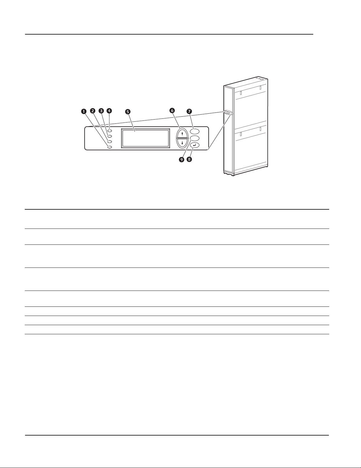
Display Interface
Status
Check
Log
Warning
Critical
Item Function
Critical Alarm LED (red) When illuminated, a critical alarm condition exists that requires your
immediate attention.
Warning Alarm LED (yellow) When illuminated, a warning alarm condition exists. Failure to correct this
condition could cause a critical alarm.
Check Log LED (yellow) When illuminated, at least one new event has been logged since the last
time the log was checked. Only events that pertain to the operation of the
cooling unit will activate this LED.
Status LED (green) When illuminated, the cooling unit is receiving electrical power. When the
LED is flashing, the cooling unit is downloading firmware for the controller.
This may take a few minutes.
Liquid Crystal Display (LCD) View alarms, status data, context-sensitive help, and modify configurable
items.
Up and down arrow keys Select menu items and access information.
ESC key Return to previous screen or cancel current operation.
Enter key Open menu items and input changes to the cooling unit settings.
Help key Display context-sensitive help. Press the help key for information about each
option on the screen and for instructions on performing the tasks.
ESC
?
na1582a
InRow SC Operation and Maintenance8
Page 15
Using the Display Interface
Every time you apply power to the cooling unit, the display interface initializes, causing the LEDs to cycle and
the alarm tone to activate.
Scrolling status screens
After start-up, the interface displays the firmware revision number of the display interface. The display interface
then scrolls automatically and continuously through screens of status information.
Status Screen Name Status Information Displayed
Schneider Electric InRow SC
Status
• On/Standby
• Cooling unit name
• Cooling unit location
Group • Alarms/No Alarms
• Cool Output kW
• Cool Setpoint °C (or °F)
• Max Rack (Maximum Rack Temperature) °C (or °F)
Unit • Alarms/No Alarms
• Cool Output kW
• Air Flow CFM (cubic feet per minute) or L/s (liters per second)
• Rack Inlet ° C (or ° F)
Press the up or down arrow key to interrupt the automatic scrolling and view a specific status screen. Screens
automatically begin to scroll after five seconds of inactivity. Press the ENTER or ESC key to return to the main
menu screen.
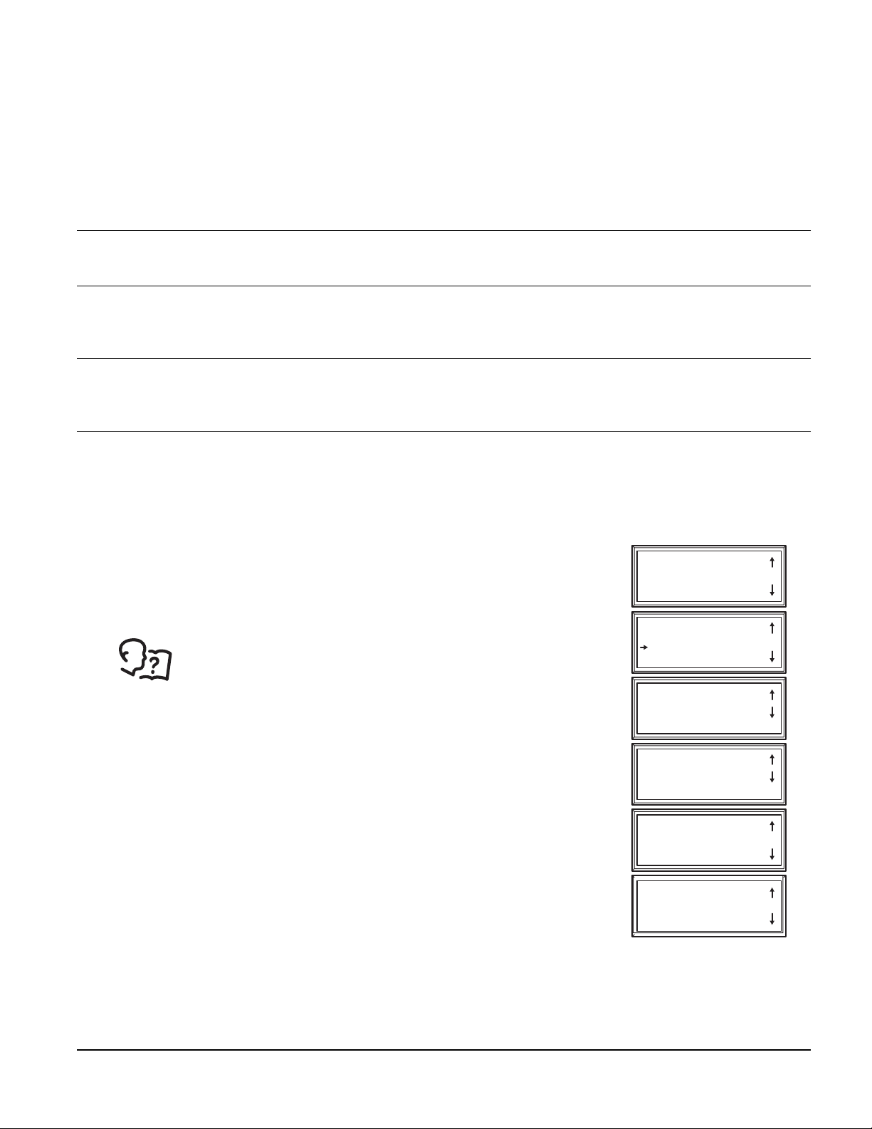
Main menu screens
On any top-level status screen, press the ENTER or ESC key to open the main
menu screen.
NOTE: If the display interface is inactive for the time configured for the
password time-out, it returns to the scrolling status screens.
For information on setting the password time-out, see “Password &
time-out” on page 20.
NOTE: Pressing the up arrow key from the top line of the top screen of the main
menu will take you to the top line of the bottom screen.
On/Standby
View Alarms
Clear Alarms
View Event Log
Clear Event Log
Configure Modbus
Set Date & Time
Set Password
Set Display Units
Configure Display
Configure Network
About InRow SC
Set Identification
Service Intervals
View Run Hours
Configure Unit
Configure Group
Set Group Setpoints
Set Unit Threshlds
View Group Status
View Unit Status
na1636f
9InRow SC Operation and Maintenance
Page 16
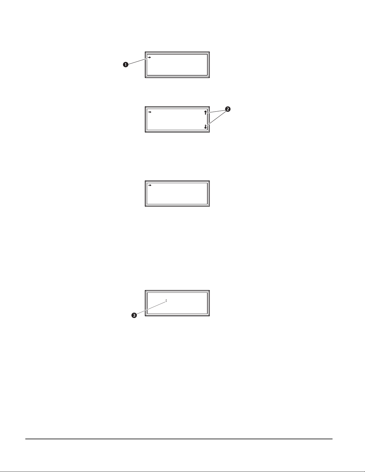
Navigating the main menu
Selector arrows: Press the up or down arrow key to move the selector arrow to a menu option or setting.
Press the ENTER key to view the selected screen or modify the setting.
Date: 18-Jun-2007
Time: 13:15:23
na0158a
Continue arrows: Continue arrows indicate that additional options or settings are available on a menu or
status screen. Press the up or down arrow key to view the additional items.
Time: 13:15:23
Date: 18-Nov-2010
Format: dd/mm/yyyy
na1623a
Navigating the sub-menus
Selecting a main menu option displays the sub-menu screen for that option. Use the up or down arrow key to
move the selector arrow to the setting that you wish to change, and press the ENTER key.
Time: 13:15:23
Date: 29-Jan-10
Format: dd-mmm-yy
na1623e
• List of choices: If the setting is a list of choices, an input arrow is displayed next to the setting. Press
the up or down arrow key to select the choice you want, and then press the ENTER key to exit the input
mode and save the setting. Press the ESC key to exit without saving.
• Numbers or text fields: If the setting is a number or text field, use the arrow keys to select the value of
the first character, and press the ENTER key to move to the next. Press the ENTER key after the last
character is set to exit the input mode and save the setting. Press the ESC key to exit without saving. If an
invalid value is entered, the display beeps and restores the previous valid value to the field.
• Input arrows: next to a selected setting indicate that the setting can be modified by pressing the up or
down arrow key. Press the ENTER key to save the change or the ESC key to cancel the change.
Time: 13:15:23
Date: 29-Jan-10
Format: dd-mmm-yy
na1622b
InRow SC Operation and Maintenance10
Page 17

Using the Path statement
Select the main- and sub-menu options specified in the path statement to view or configure a setting. The path
statement lists the main- and sub-menu items you select to navigate to the item to view or modify. The parts of
the path statement are defined below:
Path: Main > Set Password >Change Passwords
Main > Your starting point is the main menu.
Set Password > Scroll to and select this option from the main menu.
Change Passwords > Scroll to and select this option from the sub-menu.
Subsequent options are listed and defined under the path statement.
Password entry
Path: Main Menu > Set Password > Change Passwords
The cooling unit has two levels of password protection:
• Device password: for users who need to change basic and environmental settings.
• Admin password: for users who need to modify settings that control the components in the cooling unit
or change advanced options.
When you try to change any of the settings, the local display prompts you to enter your Admin password. The
default value for both the Device and Admin passwords is apc (lower case). To enter your password, use the up
or down arrow keys to scroll through the available character set. Press the ENTER key to select the current letter
and move the cursor to the next letter position. After selecting the last letter of your password, press the ENTER
key once more to submit your password. If the Device and Admin passwords have been configured to be
unique, the Admin password can be entered for the Device password, and Admin privileges will be granted.
Once the password is entered, it remains in effect until the period of inactivity exceeds the Password Time-out
setting.
See “Password & time-out” on page 20.
NOTE: Passwords are case-sensitive.
11InRow SC Operation and Maintenance
Page 18

Start the cooling unit
Path: Main Menu > On/Standby
Limiting access by requiring a password: Selecting On/Standby will
display the Operate: On/Standby screen. The second line on the screen is
Limit Access: Yes/No. Select Yes to require a password in order to stop or
start the unit. When the cursor is on Operate: On/Standby and the ENTER
On/Standby
View Alarms
Clear Alarms
View Event Log
key is pressed, the screen will display Enter Password. The password must
then be entered in order to continue. If Limit Access: No is selected, a
password is not required.
Operate: On/Standby
Limit Access: Yes
To start the cooling unit, change the setting to On by pressing the ENTER key
to toggle from Standby to On. At that point, the fans will start or Unit startup
in progress will appear if the Start-Up Delay option is set to restart multiple
Enter Password
********************
cooling units sequentially.
The cooling unit will run according to the configured settings.
NOTE: On/Standby only affects the local cooling unit. You must set the On/Standby option for each cooling
unit in the cooling group.
NOTE: To toggle between On and Standby from the scrolling status screens, press the ENTER key three times
in rapid succession. This operation can only be done if Limit Access: Yes/No is set to No.
Stop the cooling unit
na2969a
Path: Main Menu > On/Standby
NOTE: The Limit Access: Yes/No information provided above is also applicable for shutting down the unit.
Press the ENTER key to change the setting to Standby. The cooling unit will enter the standby mode.
DANGER
HAZARD OF ELECTRIC SHOCK
The Standby option does not remove power from the cooling unit. You must disconnect
power at the mains to remove power from the cooling unit.
Failure to follow these instructions will result in death or serious injury.
InRow SC Operation and Maintenance12
Page 19

General Configuration
The cooling group configuration options are set during the commissioning of the cooling units in the cooling
group.
NOTICE
HAZARD TO EQUIPMENT
This procedure must be performed by Schneider Electric qualified personnel only.
Changing the settings incorrectly can cause malfunctions to your cooling unit.
Failure to follow these instructions can result in equipment damage.
Cooling unit configuration
Path: Main > Configure Unit > General
Use the General menu to set the following:
Start-up Delay: The delay begins when the cooling unit is started and initialized. The cooling unit cannot begin
operation until this delay expires. Use the start-up delay to restart equipment sequentially in your room after a
scheduled downtime.
Idle On Leak: When set to Yes, the cooling unit will enter idle mode if a Water Detection Fault activates. Set to
No to disable the cooling unit from entering idle mode if a leak is detected.
NOTE: The leak sensor (Schneider Electric part number AP9325) is optional.
NOTE: There are six alarms that will cause the cooling unit to enter idle mode:
• Water Detection Fault (when Idle On Leak is set to Yes)
• Condensate Pump Fault
• Cooling Failure
• Low Suction Pressure Fault
• High Discharge Pressure Fault
• Critical Sensor Failure
13InRow SC Operation and Maintenance
Page 20

Contacts
View the state of input and output contacts
Path: Main > Configure Unit > Discrete I/O
Each cooling unit supports a user-defined input contact and a user-defined output contact. Each contact
monitors a sensor and responds to changes in the state of the sensor (open or closed).
Input State: Indicates the actual state of the input contact (Open or Closed). A cooling unit is On when the
state is normal and in Standby when the state is not normal.
Output State: Indicates the actual state of the output contact (Open or Closed). An alarm will cause the output
contact to change from the normal state.
Edit the normal state of input and output contacts
Path: Main > Configure Unit > Discrete I/O > Normal State
Configure the input contacts to cause alarm conditions based on the user-defined normal state. Output contacts
can map internal alarms and events to outside devices.
Input Norm: Set the normal state of the contact (Open or Closed). The cooling unit changes its operating
mode to Closed when the actual state differs from the normal state.
Output Norm: Set the normal state of the contact (Open or Closed). If the state of an alarm or event mapped
to this contact changes from the normal state, the contact also changes state.
Outpt Src: Define the type of output source (alarm), either Any Alrm or Critical, that causes the output to
change from its normal state.
InRow SC Operation and Maintenance14
Page 21

Cooling Group Configuration
Use the cooling group configuration settings to add cooling units to the group and to define group operation.
NOTE: Schneider Electric recommends that this procedure be performed by Schneider Electric qualified
personnel only. The settings in the Configure Group menu are defined by Schneider Electric qualified
personnel when the cooling group is commissioned.
Configure the cooling group
Path: Main > Configure Group
The Configure Group menu contains settings that identify the number of cooling units installed in this cooling
group and the physical arrangement of those cooling units.
Num Units: Enter the number of cooling units in this cooling group. Up to 12 cooling units can be joined
together to work as a single cooling group.
Type: Set the rack deployment strategy for the cooling units of this cooling group:
• Spot: The cooling unit is used as a stand-alone unit.
• InRow: Air flow is not ducted. Hot-aisle air is cooled and the cooled-air supply is shared by all loads in
the row.
• RACS (Rack Air Containment System): Air flow in the enclosure is controlled by a ducting system fitted
to the enclosure.
Capacity Ctrl: Set the capacity control of the cooling unit:
• Disc (Discrete): The cooling unit operates as a room air conditioner. The evaporator fan speed will
remain constant at the user setting and the compressor will cycle on and off to maintain the cool setpoint.
NOTE: The Disc mode is only available in a Spot cooling configuration.
• Prop (Proportional): The cooling unit matches the cooling output to the load demand. This is
accomplished using hot gas adjustment and fan speed control. Load demand is determined by the cool
setpoint and the temperature sensor at the rear of the cooling unit (in Spot configurations) or the
temperature sensor at the front of the load rack (in InRow and RACS configurations) or differential
pressure data from AFC if present (in RACS configuration).
Fan Cntrl: This selection allows air flow to be controlled automatically by the cooling unit or manually by
user-selected fan speed preference. This property only applies to Spot (Proportional), InRow, and RACS
deployments.
• Auto: Air flow is automatically controlled by the unit.
• Manual: the air flow is fixed to the value of the Fan Speed Preference property.
Altitude: The height of the cooling unit above sea level. This number is used to estimate the density of the air
and is a factor in both calculating the output power and pressure measurement. Enter the altitude to the nearest
meter or foot for best results. Entries to the nearest 305 meters (1,000 feet) should be sufficient.
Active Flow Control Lamp Test: When enabled, the Active Flow Controller(s) LEDs will cycle through a red,
green, and blue illumination pattern. (Not on unit.)
Number of Active Flow Controllers: Set the number of AFC units in the group (0-5).
15InRow SC Operation and Maintenance
Page 22

Identify the cooling unit
Path: Main >Set Identification
The Set Identification menu contains settings that identify the name and location of the cooling unit.
Name: Assign a Name of up to 40 alpha-numeric characters to this cooling unit.
Location: Enter the Location, up to 40 alpha-numeric characters, of the cooling unit.
NOTE: Only the first 19 characters (of the 40 that are possible to enter) will display on the display interface. You
must use Telnet, the Control console or the Web to access all 40 characters. See “Telnet and SSH” on page 34
for more information.
Configure Modbus
Path: Main > Configure Modbus
Use the Configure Modbus menu to set up communication between the cooling unit and the building
management system.
Modbus: Enable or Disable the Modbus communication protocol.
Target Id: Each Modbus device must have a unique target identification number. Enter a unique number, from
1 to 247, for this cooling unit.
Baud Rate: Choose either 9600 bps or 19200 bps.
Fixed settings: 8 data bits, no parity, 1 stop bit. These settings cannot be modified.
To access the Modbus register map, go to the Schneider Electric Web site,
www.schneider-electric.com.To access the Modbus register map, go to the Schneider Electric
Web site, www.schneider-electric.com.
InRow SC Operation and Maintenance16
Page 23

Control the Environment
The main function of the cooling unit is to remove waste heat and return treated air to the room at the required
temperature. The control strategies employed by the cooling unit depend upon the deployment strategy of the
cooling group.
In an InRow environment, the cooling unit supplies constant-temperature supply air to the common cold aisle.
The fan speed is modulated to ensure that the required volume of air reaches the IT equipment. The fan speed
is determined by the difference between the cooling setpoint and the maximum rack air inlet temperature of the
cooling group.
In a RACS environment, the front and rear of the IT equipment racks are fully enclosed. Waste heat is funneled
directly to the return air of the cooling unit so the heat cannot escape into the room. Cool air is delivered directly
from the cooling unit to the IT equipment racks. When Active Flow Controller (AFC) devices are present, the
controller utilizes differential pressure data supplied by the AFC(s) to supply the correct amount of airflow to the
IT load. When AFC devices are not present, the fan speed is controlled by the fan speed preference setting.
The fan speed can be selected based on the temperature differential across the cooling unit.
In a Spot cooling environment, the cooling unit operates like traditional computer room air conditioning (CRAC)
equipment, providing a constant return air temperature. In Disc (Discrete) mode, the fans operate at a userselectable speed (Fan Control) and the compressor operates at maximum capacity. In Prop (Proportional)
mode, the fans are modulated to maintain the required return air temperature and the compressor output is
modulated to maintain the necessary supply air temperature.
Setpoints
Path: Main > Set Group Setpoint
A setpoint is the target value that a cooling group will maintain. The default setpoints are appropriate for most
cooling applications.
Default setpoints:
• Cool: 22.2 °C (72.0°F)
• Deadband: 1.0°C (1.8°F)
• Supply Air:
15.0 °C (57 – 59.0°F) Spot (Proportional) only
17.8°C (64.0°F) RACS or In-Row
NOTE: The Supply Air setting is defined by Schneider Electric authorized personnel only when the
cooling group is commissioned.
NOTE: The Supply Air setpoint must never be set higher than the Cool setpoint.
• Fan Spd: When the unit is programmed for RACS mode and no AFC(s) are present, this property
specifies the necessary temperature difference (DT) across the IT equipment. When the cooling unit is
programmed for Spot (Proportional), In-Row, or RACS with the Fan Control property set to Manual,
this property defines the fan speed. When the cooling unit is programmed for Spot (Discrete), the fan
speeds are also selected from the following table but the Fan Control property is irrelevant.
– Low: 16.7°C (30°F) DT (60% of maximum fan speed)
– Med-Low: 13.9°C (25°F) DT (70% of maximum fan speed)
– Med: 11.1°C (20°F) DT (80% of maximum fan speed)
– Med-High: 6.3°C (15°F) DT (90% of maximum fan speed)
– High: 5.6°C (10°F) DT (100% of maximum fan speed)
17InRow SC Operation and Maintenance
Page 24

Active Flow Control Bias: This setting is used to change the bias of the controller by adjusting the contained
aisle pressure threshold. Zero is the default setting. Only qualified service personnel can make changes to
these settings.
• Hot Aisle Containment (HACS)
– If the cooling units seem to be under-cooling, select Negative or Slightly Negative to adjust the aisle
pressure for additional cooling.
– If the cooling units seem to be over-cooling, select Positive or Slightly Positive to adjust the aisle
pressure for less cooling.
• Cold Aisle Containment (CACS)
– If the cooling units seem to be under-cooling, select Positive or Slightly Positive to adjust the aisle
pressure for additional cooling.
– If the cooling units seem to be over-cooling, select Negative or Slightly Negative to adjust the aisle
pressure for less cooling.
Blue LED – HACS
Setting
Positive
Slightly Positive
Zero
Slightly Negative
Negative
Active Flow Control Status: Displays the status of the Active Flow Control. This status indicates whether the
correct amount of airflow is being provided to the load. This status is not configurable.
NOTE: AFC compatibility may require upgrading the cooling unit controller.
Red LED – CACS
< –0.008 in. ±3% 0.004 ±0.0004 in. > 0.016 in. ±3%
< –0.010 in. ±3% 0.002 ±0.0004 in. > 0.014 in. ±3%
< –0.012 in. ±3% 0.000 ±0.0004 in. > 0.012 in. ±3%
< –0.014 in. ±3% –0.002 ±0.0004 in. > 0.010 in. ±3%
< –0.016 in. ±3% –0.004 ±0.0004 in. > 0.008 in. ±3%
Setpoint
Green LED
Red LED – HACS
Blue LED – CACS
Run hours
Path: Main > View Run Hours
The cooling unit records the number of hours each of its components has operated. When a component is
replaced, use the Reset option to reset the run hours for the displayed component to zero.
Path: Main > View Run Hours > Air Filter
• Air Filter
• Reset Run Hours
Path: Main > View Run Hours > Fans > Condenser
• Fan n (n = 1, 2, or 3)
• Reset Run Hours
Path: Main > View Run Hours > Fans > Evaporator
• Fan n (n = 1, 2, or 3)
• Reset Run Hours
Path: Main > View Run Hours > Compressor
• Compressor
• Reset Run Hours
InRow SC Operation and Maintenance18
Page 25

Path: Main > View Run Hours > Condensate Pump
• Conds Pump (Condensate Pump)
• Reset Run Hours
Path: Main > View Run Hours > Fan Power Supplies
• LT Fan PS (Left Fan Power Supply)
• RT Fan PS (Right Fan Power Supply)
• Reset LT PS Hours (Reset Left Fan Power Supply Hours)
• Reset RT PS Hours (Reset Right Fan Power Supply Hours)
Thresholds
Set alarms to alert you when components require service or there are high temperature violations.
Path: Main > Set Unit Thresholds
When the air temperature exceeds the temperature defined by the High Temperature Threshold, an alarm will
occur. Set High Temperature Thresholds for the following:
• Rack Inlet: An alarm condition exists when the temperature of the air entering the rack at the rack inlet
sensor exceeds the threshold.
• Supply Air: An alarm condition exists when the temperature of the air output from the cooling unit
exceeds the threshold.
• Return Air: An alarm condition exists when the temperature of the air entering the cooling unit at the
temperature sensor exceeds the threshold.
Service intervals
Path: Main > Service Intervals
The air filters should be serviced regularly. The service interval depends on environmental cleanliness.
• Air Filter Interval: Set the number of weeks before service is required for the Air Filter Interval. The
default is 18 weeks.
• Alarm: The interval setting has an alarm (Enable or Disable). If enabled, an audible alarm activates
when the interval has elapsed. The alarm is cleared by selecting Clear Alarms in the main menu.
NOTE: The Air Filter interval alarm is enabled by default.
19InRow SC Operation and Maintenance
Page 26

Display Settings
Set display settings, including the time and date, units, passwords, and time-out settings. You can also adjust
contrast, key click, beeper volume, and beep on alarm.
Password & time-out
Path: Main > Set Password
NOTE: The default user password is apc (lowercase).
Change passwords: Set the Admin and Device passwords.
1. Move the selector arrow next to the Change Passwords option and press the ENTER key.
2. Select the password to change (either Admin or Device).
3. Enter a new password (up to 8 characters).
4. Press the ENTER key to confirm.
Time-out: Set the length of time which can elapse when no keys are pressed before the display interface
returns to the scrolling screen status. The password must then be entered to regain access.
Invalidate Now: Override the password time-out and require password entry immediately.
Date and time
Path: Main > Set Date & Time
Set the time: Enter the correct time, and press the ENTER key. The Time is displayed on some status screens
and is also used in the alarm/event log to time-stamp events.
Set the date: Enter the day, month, and year, and press the ENTER key. The Date is displayed on some status
screens and is also used in the alarm/event log to date-stamp events.
Set the format: Use the up or down arrow keys to select the date Format.
• mm/dd/yyyy (02/10/2009) (Default)
• yyyy-mm-dd (2009-02-10)
• dd-mmm-yy (10-Feb-09)
• mmm-dd-yy (Feb-10-009)
• dd.mm.yyyy (10.02.2009)
InRow SC Operation and Maintenance20
Page 27

Configure display
Path: Main > Configure Display
Contrast: Adjust the visibility of the screen text. Lower numbered settings provide darker text; higher numbers
provide lighter text. Settings range from 0 – 7.
Key Click: Set to ON or OFF will enable or disable an audible tone that sounds every time a key is pressed on
the display interface.
Beeper Volume: Set the volume (Low, Medium, High or OFF) of the audible tone that sounds every time a
key is pressed on the display interface.
Beep on Alarm: Set to ON or OFF. When set to ON, the cooling unit will sound an audible tone every 30
seconds when a new alarm occurs. Silence the audible tone by pressing any key on the display interface.
When the alarm clears itself, the tone will stop on its own.
Display units
Path: Main > Set Display Units
Set the units of measure for the cooling unit to either US or Metric.
21InRow SC Operation and Maintenance
Page 28

Network Configuration
The cooling unit is shipped with a Network Management Card that enables the cooling unit to be managed over
a network. Configure the network settings for the Network Management Card for this cooling unit from the
display interface. The management card allows remote control and configuration of the equipment.
Configure network
Path: Main > Configure Network
MAC Address: Displays the unique network identifier assigned to each cooling unit at the factory.
Boot Mode: Set the method by which the cooling unit Network Management Card will acquire its network
settings.
• Manual: With Manual boot mode selected, enter the IP Address, Subnet Mask, and Default Gateway
using the IP Address menu shown below.
• BootP: Set the Network Management Card to obtain its network settings from a BootP server.
• DHCP: Set the Network Management Card to obtain its network settings from a DHCP server.
By default, DHCP requires a cookie before it will accept an IP address. See “DHCP:”
on page 31 for more information.
• BootPDHCP: Set the Network Management Card to search for its network settings from either a BootP
or a DHCP server.
IP Address: You will be prompted to enter the Admin password. Enter the password and press ENTER to return
to the IP screen. Press ENTER again to change the network settings for Manual boot mode only:
• IP: Enter the IP address assigned to the Network Management Card of this cooling unit.
• SM: Enter the subnet mask for the Network Management Card of this cooling unit.
• GW: Enter the default gateway for the Network Management Card of this cooling unit.
InRow SC Operation and Maintenance22
Page 29

View Status Readings
The display interface has several options for viewing the status of the cooling unit, the cooling group to which
the cooling unit belongs, and the environment being controlled. The status readings for the cooling unit are
available under the View Unit Status option in the main menu, and status readings for the cooling group are
available under the View Group Status option on the main menu or on the scrolling status screens.
Scrolling status screens
When the display interface is idle, it scrolls through screens of status information. Press the up or down arrow
key to interrupt the automatic scrolling and view a specific status screen.
Cooling unit status
Path: Main > View Unit Status
Op Mode: The cooling unit is in one of the following modes:
• On: The cooling unit is cooling.
• Standby: The cooling unit is receiving power but is not enabled for cooling.
• Idle: The cooling unit is on, but the compressor is not running because it has active alarms.
Cool Output: The actual cooling output of the cooling unit.
Cool Demand: The amount of cooling that the heat load currently requires.
Rack Inlet: The temperature of the air entering the rack at the remote temperature sensor.
Supply Air: The temperature of the air leaving the cooling unit.
Return Air: The temperature of the air entering the cooling unit.
Cond Outlet: The temperature of the air leaving the condenser.
Cond Inlet: The temperature of the air entering the condenser.
Suction Temp: The temperature of the low pressure refrigerant line.
Air Flow: The amount of air flowing through the evaporator required to maintain the setpoint temperature.
Evap Fan Spd: The speed of the fans that regulate the air flow through the evaporator.
Cond Fan Spd: The speed of the fans that regulate air flow through the condenser.
Input State: The actual state of the input contact (open or closed).
Output State: The actual state of the output contact (open or closed).
Filter DP: The filter differential pressure.
Suction: The pressure at the compressor inlet.
Discharge: The pressure at the compressor outlet.
Superheat: The difference between the Suction Temp and the evaporator dew point temperature.
Compressor: The state of the compressor, either on or off.
23InRow SC Operation and Maintenance
Page 30

Cooling group status
Path: Main > View Group Status
View information about the cooling group.
Cool Output: The combined output of the cooling group.
Cool Demand: The cooling output required to meet the current heat load of the conditioned space.
Cool Setpt: The temperature you set to maintain the room environment.
Air Flow: The combined airflow output of the cooling units in the cooling group.
Max Rack: The highest rack temperature reported by any cooling unit in the cooling group.
Min Rack: The lowest rack temperature reported by any cooling unit in the cooling group.
Max Return: The highest return temperature reported by any cooling unit in the cooling group.
Min Return: The lowest return temperature reported by any cooling unit in the cooling group.
About the cooling unit
Paths: Main > About InRow SC
View identifying information that is helpful when obtaining service:
• Model
• S/N Number (Serial Number)
• F/W (Firmware Version)
• H/W (Hardware Version)
• Made (Date of Manufacture)
• SC App (Application Version)
• AOS Ver (NMC Operating System Version)
InRow SC Operation and Maintenance24
Page 31

Event Log
The event log saves status information and a message each time a change in the cooling unit is detected.
Alarms events are recorded in the log and displayed on the active alarm screens. Status (informational) events
and system configuration changes are only displayed in the event log. The number of messages in the event
log is limited to 500. When the number of messages in the event log reaches 500, the oldest message will be
dropped from the list every time a new message is added to the log.
View event log
Path: Main > View Event Log
The event log keeps a record of all alarms and events. The screen displays the following:
• The name of the event
• The time and date the event occurred
Use the arrow keys to scroll through the list of events and display the date and time for each event.
Clear event log
Path: Main > Clear Event Log
A confirmation screen is displayed when you select this option. Enter the Admin password to erase the log.
Select YES to erase all of the events in the log. Select NO to return to the main screen.
Respond to Alarms
When an alarm is triggered, the cooling unit alerts you through the display by the following methods:
• Alarm screen entry on scrolling status screens
• LEDs on the front panel display
• An optional audible alarm every 30 seconds (if enabled)
View alarms
Path: Main > View Alarms
The View Alarms screen provides the number of alarms, the severity, and a brief description of the alarm.
Press the arrow keys to view the rest of the list.
Clear active alarms
Path: Main > Clear Alarms
A confirmation screen is displayed when you select this option. Enter the Admin password to clear the alarm
list. Select YES to clear all of the alarms in the list. Select NO to return to the main screen. If the conditions that
caused the alarm still exist, those conditions cause the alarm to be regenerated.
NOTE: A Critical fault prevents the system from performing its primary function. A primary function is defined as
any function that can effect the ability to deliver rated cooling performance. A Warning fault is a fault that is not
critical.
25InRow SC Operation and Maintenance
Page 32

Alarm messages and suggested actions
Displayed Alarm Message Severity Action Required
Air Filter Clogged Warning • Clean or replace the air filter.
• If the problem persists, contact Schneider Electric Customer
Support.
Air Filter Run Hours Violation Warning • Reset the Air Filter Run Hours after the air filter is cleaned or
replaced.
A-Link Isolation Relay Fault Critical • A hardware failure exists. For assistance, contact Schneider Electric
Customer Support.
Condensate Pan Full Fault Critical • Make sure the floats are operating correctly.
• Clear debris from the condensate pan and drain lines.
• If the problem persists, contact Schneider Electric Customer
Support.
Check Condensate Management
System
Condenser Fan #n Fault Warning • Make sure all air intakes are clear of any blockage.
Condenser Inlet Air Sensor Fault Warning • A hardware failure exists. For assistance, contact Schneider Electric
Condenser Outlet Air Sensor
Fault
Cooling Failure Critical • A hardware failure exists. For assistance, contact Schneider Electric
Discharge Pressure Sensor Fault Warning • A hardware failure exists. For assistance, contact Schneider Electric
Evaporator Fan #n Fault Warning • Make sure all air intakes are clear of any blockage.
External Communication Fault Critical • A hardware failure exists. For assistance, contact Schneider Electric
Fan Power Supply Left Fault Warning • Replace the power supply.
Fan Power Supply Right Fault Warning • Replace the power supply.
Filter Sensor Fault Warning • A hardware failure exists. For assistance, contact Schneider Electric
High Discharge Pressure Alarm Critical • For assistance, contact Schneider Electric Customer Support.
Internal Communication Fault Critical • A hardware failure exists. For assistance, contact Schneider Electric
Low Suction Pressure Alarm Warning • For assistance, contact Schneider Electric Customer Support.
Rtn Air High Temp
(Return Air High Temperature
Violation)
Warning • Clear debris from the condensate pump reservoir and the
condensate removal lines.
• Make sure the condensate removal lines are free of obstructions and
the float switch moves freely.
• For assistance, contact Schneider Electric Customer Support.
NOTE: Fans are numbered sequentially, starting with Fan 1 at the
front of the cooling unit.
• If the problem persists, contact Schneider Electric Customer
Support.
Customer Support.
Warning • A hardware failure exists. For assistance, contact Schneider Electric
Customer Support.
Customer Support.
Customer Support.
Note:Fans are numbered sequentially, starting with Fan 1 at the
bottom.
• If the problem persists, contact Schneider Electric Customer
Support.
Customer Support.
• For assistance, contact Schneider Electric Customer Support.
• For assistance, contact Schneider Electric Customer Support.
Customer Support.
Customer Support.
Warning • Make sure the Return Air threshold is set correctly in the Set Unit
Threshlds screen.
• If the problem persists, contact Schneider Electric Technical
Support.
InRow SC Operation and Maintenance26
Page 33

Displayed Alarm Message Severity Action Required
Sply Air High Temp
(Supply air High Temperature
Violation)
Warning • Make sure the Supply Air threshold is set correctly in the Set Unit
Threshlds screen.
• If the problem persists, contact Schneider Electric Technical
Support.
Persistent High Discharge
Critical • For assistance, contact Schneider Electric Customer Support.
Pressure Alarm
Persistent Low Suction Pressure
Alarm
Critical • Indicates there were 3 Low Suction Pressure shutdowns in 30
minutes. Alarms must be cleared manually.
• For assistance, contact Schneider Electric Customer Support.
Rack Inlet High Temperature
Violation
Critical • Make sure the Rack Inlet High Temperature Threshold is set
correctly in the "Thresholds" screen.
• Make sure remote temperature sensor is installed correctly in the
rack inlet air stream.
• If the problem persists, contact Schneider Electric Customer
Support.
Rack Inlet Temperature Sensor
Critical • For assistance, contact Schneider Electric Customer Support.
Fault
Suction Pressure Sensor Fault Warning • A hardware failure exists. For assistance, contact Schneider Electric
Customer Support.
Suction Temperature Sensor
Fault
Warning • A hardware failure exists. For assistance, contact Schneider Electric
Customer Support.
Water Detection Fault Warning • Identify the source of the leak.
• For assistance, contact Schneider Electric Customer Support.
Grp Comm Fault
(Group Communication Fault)
Warning • Make sure the number of cooling units in the group is configured
properly and the A-Link connections between cooling units are
correct.
• Make sure the system is receiving power and is connected properly.
• A hardware failure exists. For assistance, contact Schneider Electric
Customer Support.
Input Contact Fault Warning • Make sure the Input Normal state is defined correctly in the
Configure Unit > Discrete I/O screen. See “View the state of input
and output contacts” on page 14 for more information.
• Clear the problem that caused the input contact switch to change
from the normal state.
• If the problem persists, contact Schneider Electric Customer
Support.
Cannot Start Due to Low Suction
Pressure
Critical • The unit cannot start because the suction (low side) refrigerant
pressure is too low.
• If the problem persists, contact Schneider Electric Customer
Support.
Startup Line Pressure Imbalance
Alarm
Critical • The unit cannot start because the line pressure is too low.
• If the problem persists, contact Schneider Electric Customer
Support.
Return Air Sensor Fault Critical • A hardware failure exists. For assistance, contact Schneider Electric
Customer Support.
Supply Air Sensor Fault Critical • A hardware failure exists. For assistance, contact Schneider Electric
Customer Support.
Water Detection Shutdown Critical • For assistance, contact Schneider Electric Customer Support.
EcoAisle Door Open Warning • Verify the EcoAisle door is shut properly.
• If the problem persists, contact Schneider Electric technical support.
27InRow SC Operation and Maintenance
Page 34

Displayed Alarm Message Severity Action Required
Unexpected Number of Active
Flow Controllers
Warning • Verify physical number of AFC units matches the number shown in
the Number of Active Flow Controllers setting.
• If the problem persists, contact Schneider Electric technical support.
Insufficient Airflow Warning • Verify the air ports are clear of obstructions and there is sufficient
cooling capacity for the load.
• If the problem persists, contact Schneider Electric technical support.
Active Flow Controller Sensor
Fault
Warning • A hardware failure exists. For assistance, contact Schneider Electric
Customer Support.
InRow SC Operation and Maintenance28
Page 35

Network Management Card
Quick Configuration
The cooling unit is shipped with a Network Management Card that enables the cooling unit to be managed over
a network. Configure the Network Management Card to control this cooling unit through a network.
Overview
You must configure the following TCP/IP settings before the Network Management Card can operate on a
network:
• IP address of the Network Management Card
• Subnet mask
• Default gateway
IMPORTANT: Never use the loopback address (127.0.0.1) as the default gateway address for the
Network Management Card. Doing so will disable the card and will require you to reset TCP/IP settings
to their defaults using a local serial login.
OTE: If a default gateway is unavailable, use the IP address of a computer that is located on the same
N
subnet as the Network Management Card and that is usually running. The Network Management Card
uses the default gateway to test the network when traffic is very light.
See “Watchdog Features” in the “Introduction” of the User Guide for more information about
the watchdog role of the default gateway.
TCP/IP configuration methods
Use one of the following methods to define the basic TCP/IP settings needed by the Network Management
Card:
• Schneider Electric Device IP Configuration Wizard (See “Device IP Configuration Wizard” on page 30.)
• BootP or DHCP server (See “BootP & DHCP configuration” on page 30.)
• Networked computer (See “Remote access to the control console” on page 32.)
29InRow SC Operation and Maintenance
Page 36

Device IP Configuration Wizard
The Device IP Configuration Wizard is used to discover and configure Network Management Cards that do not
have IP addresses assigned. The Device IP Configuration Wizard runs on Microsoft® Windows® 2000,
Windows Server® 2003, Windows Server 2012, and on 32- and 64-bit versions of Windows XP, Windows Vista,
Windows 2008, Windows 7, and Windows 8 operating systems.
The Device IP Configuration Wizard supports cards that have firmware version 3.0.x or higher and is for IPv4
only.
NOTE: Most software firewalls must be temporarily disabled for the Wizard to discover Network Management
Cards that are not configured.
To configure one or more Network Management Cards from a user configuration file, see the User
Guide available on the Schneider Electric Web site: www.schneider-electric.com.
1. Download the Device IP Configuration Wizard from the Schneider Electric Web site: www.schneider-
electric.com.
2. Install and run the Device IP Configuration Wizard.
3. Follow the on-screen instructions.
NOTE: If you leave the Start a Web browser when finished option enabled, you can use apc for both
the user name and password to access the Network Management Card through your browser.
.ini file utility
You can use the .ini file export utility to export .ini file settings from configured Network Management Cards to
one or more unconfigured Network Management Cards. The utility and documentation are included on the
Schneider Electric Web site: www.schneider-electric.com.
BootP & DHCP configuration
The default TCP/IP configuration setting, BootP & DHCP, assumes that a properly configured BootP or DHCP
server is available to provide TCP/IP settings to Network Management Cards. The Network Management Card
first attempts to discover a properly configured BootP server, and then a DHCP server. It repeats this pattern
until it discovers a BootP or DHCP server.
If neither of these servers is available, see “Local access to the control console” on page 31 or
“Remote access to the control console” on page 32 to configure the needed TCP/IP settings.
A user configuration (.ini) file can function as a BootP or DHCP boot file. For more information, see
the TCP/IP configuration section of the User Guide, available from the Schneider Electric Web site,
www.schneider-electric.com.
BootP: For the Network Management Card to use a BootP server to configure its TCP/IP settings, it must find
a properly configured RFC951-compliant BootP server.
1. In the BootPTAB file of the BootP server, enter the MAC address of the Network Management Card, the
IP address, the subnet mask, default gateway, and an optional bootup file name. Look for the MAC
address on the display interface (Path: Main > Configure Network) or on the label on the back of the
Network Management Card.
2. When the Network Management Card reboots, the BootP server provides it with the TCP/IP settings.
– If you specified a bootup file name, the Network Management Card attempts to transfer that file from
the BootP server using TFTP or FTP. The Network Management Card assumes all settings specified
in the boot-up file.
– If you did not specify a bootup file name, you can configure the other settings of the Network
Management Card remotely through its Web interface or control console; user name and password
are both apc, by default.
InRow SC Operation and Maintenance30
Page 37

See your BootP server documentation to create a bootup file.
DHCP: You can use a RFC2131/RFC2132-compliant DHCP server to configure the TCP/IP settings for the
Network Management Card.
This section summarizes communication between the Network Management Card and a DHCP
server. For more detail about how a DHCP server can configure the network settings for a Network
Management Card, see “DHCP Configuration” in the User Guide.
1. A Network Management Card sends out a DHCP request that uses the following to identify itself:
– A Vendor Class Identifier (APC by default)
– A Client Identifier (by default, the MAC address value of the Network Management Card)
– A User Class Identifier (by default, the identification of the application firmware of the Network
Management Card)
2. A properly configured DHCP server responds with a DHCP offer that includes all of the settings that the
Network Management Card needs for network communication. The DHCP offer also includes the
Vendor Specific Information option (DHCP option 43). By default, the Network Management Card will
ignore DHCP offers that do not encapsulate the cookie in the Vendor Specific Information option using
the following hexadecimal format:
Option 43 = 01 04 31 41 50 43
where
– the first byte (01) is the code
– the second byte (04) is the length
– the remaining bytes (31 41 50 43) are the cookie
See your DHCP server documentation to add code to the Vendor Specific Information
option.
To disable the requirement that a DHCP offer include the cookie, use the DHCP Cookie Is
setting in the control console:
Network>TCP/IP>Boot Mode>DHCP only>Advanced>DHCP Cookie Is.
Local access to the control console
You can use a computer connected to the serial port on the main board holding the Network Management Card
to access the control console.
1. Select a serial port at the local computer, and disable any service that uses that port.
2. Use the provided configuration cable to connect the selected port to the serial port on the main board
holding the Network Management Card.
3. Run a terminal program (such as HyperTerminal) and configure the selected port for 9600 or 19200 bps,
8 data bits, no parity, 1 stop bit, and no flow control. Save the changes.
4. Press ENTER to display the User Name prompt.
5. Use apc for the user name and password.
See “Control console” on page 32 to finish the configuration.
31InRow SC Operation and Maintenance
Page 38

Remote access to the control console
From any computer on the same subnet as the Network Management Card, you can use ARP and Ping to
assign an IP address to a Network Management Card, and then use Telnet to access the control console of that
Network Management Card and configure the needed TCP/IP settings.
NOTE: After the IP address of the Network Management Card is configured, you can use Telnet without first
using ARP and Ping to access that Network Management Card.
1. Use the MAC address for the Network Management Card in the ARP command to define the IP
address. For example, to define an IP address of 156.205.14.141 for a Network Management Card that
has a MAC address of 00 c0 b7 63 9f 67, use one of the following commands:
– Windows command format:
arp -s 156.205.14.141 00-c0-b7-63-9f-67
– LINUX command format:
arp -s 156.205.14.141 00:c0:b7:63:9f:67
NOTE: The MAC address is available on the display interface at:
Path: Main > Configure Network
Card for the MAC address.
2. Use Ping with a size of 113 bytes to assign the IP address defined by the ARP command. For the IP
address defined in step 1, use one of the following Ping commands:
– Windows command format:
ping 156.205.14.141 -l 113
or look at the label on the back of the Network Management
– LINUX command format:
ping 156.205.14.141 -s 113
3. Use Telnet to access the Network Management Card at its newly assigned IP address. For example:
telnet 156.205.14.141
4. Use apc for both user name and password.
See “Control console” on page 32 to finish the configuration.
Control console
After you log on at the control console, as described in “Local access to the control console” on page 31 or
“Remote access to the control console” on page 32:
1. Choose Network from the Control Console menu.
2. Choose TCP/IP from the Network menu.
3. If you are not using a BootP or DHCP server to configure the TCP/IP settings, select the Boot Mode
menu and then select Manual boot mode.
4. Set the System IP, Subnet Mask, and Default Gateway address values. (Changes will take effect
when you log out.)
5. Press ENTER to return to the TCP/IP menu.
6. Press CTRL+C to exit to the Control Console menu.
7. Log out (option 4 in the Control Console menu).
NOTE: If you disconnected a cable from the local computer during the procedure described in “Local
access to the control console” on page 31, reconnect that cable and restart the associated service.
InRow SC Operation and Maintenance32
Page 39

Access a Configured Network Management Card
Overview
After the Network Management Card is running on your network, you can access the configured Network
Management Card through the following interfaces:
• Web interface (HTTP or HTTPS protocol)
• Telnet or Secure SHell (SSH)
• SNMP
• FTP or Secure CoPy (SCP) to upgrade firmware
• Modbus
For more information on the interfaces, see the User Guide.
Web interface
Use Microsoft® Internet Explorer® (IE) 5.5 and higher (on Windows operating systems only), Mozilla® Firefox®
1.x (on all operating systems), or Netscape® 7.x and higher (on all operating systems) to access the Web
interface of the cooling unit. Other commonly available browsers may also work but have not been fully tested
by Schneider Electric.
You can use either of the following protocols when you use the Web interface:
• The HTTP protocol (enabled by default), which provides authentication by user name and password but
no encryption.
• The HTTPS protocol, which provides extra security through Secure Sockets Layer (SSL) or Transport
Layer Security (TLS); encrypts user names, passwords, and data being transmitted; and authenticates
the Network Management Card by means of digital certificates.
To access the Web interface and configure the security of your device on the network:
1. Address the Network Management Card by its IP address or DNS name (if configured).
2. Enter the user name and password (by default, apc and apc for an Administrator).
3. To enable or disable the HTTP or HTTPS protocols, use the Network menu on the Administration tab,
and select the Access option under the Web heading on the left navigation menu.
For more information on selecting and configuring network security, see the Security
Handbook, available on the Schneider Electric Web site, www.schneider-electric.com.
33InRow SC Operation and Maintenance
Page 40

Telnet and SSH
You can access the control console through Telnet or Secure SHell (SSH), depending on which is enabled.
Select the Administration tab, the Network option on the top menu bar, and then the Access option under
Console on the left navigation menu. By default, Telnet is enabled. Enabling SSH automatically disables
Telnet.
Telnet for basic access: Telnet provides the basic security of authentication by user name and password, but
not the high-security benefits of encryption. To use Telnet to access the control console of the Network
Management Card:
1. At a command prompt, use the following command line, and press ENTER:
telnet address
As address, use the IP address of the Network Management Card (or DNS name if configured).
2. Enter the user name and password (by default, apc and apc for an Administrator, or device and apc for
a Device User).
SSH for high-security access: If you use the high security of SSL or TLS for the Web interface, use Secure
SHell (SSH) for access to the control console. SSH encrypts user names, passwords, and transmitted data.
The interface, user accounts, and user access rights are the same whether you access the control console
through SSH or Telnet, but to use SSH, you must first configure SSH and have an SSH client program installed
on your computer.
See the User Guide for more information on configuring and using SSH.
Simple Network Management Protocol (SNMP)
SNMPv1 only: After you add the PowerNet® MIB to a standard SNMP MIB browser, you can use that browser
to access the Network Management Card. All user names, passwords, and community names for SNMP are
transferred over the network as plain text. The default read community name is public; the default read/write
community name is private.
SNMPv3 only: For SNMP GETs, SETs, and trap receivers, SNMPv3 uses a system of user profiles to identify
users. An SNMPv3 user must have a user profile assigned in the MIB software program to perform GETs and
SETs, browse the MIB, and receive traps. The default settings are no authentication and no privacy.
NOTE: To use SNMPv3, you must have a MIB program that supports SNMPv3.
NOTE: The Network Management Card supports only MD5 authentication and DES encryption.
SNMPv1 and SNMPv3: To use StruXureWare Data Center Expert to manage the Network Management Card,
you must have SNMPv1 enabled in the interface of the cooling unit. Read access allows InfraStruXure devices
to receive traps from the cooling unit. Write access is required while you set the InfraStruXure device as a trap
receiver.
To enable or disable SNMP access, you must be an Administrator. Select the Administration tab, select the
Network menu on the top menu bar, and use the access option under SNMPv1 or SNMPv3 on the left
navigation menu.
FTP/SCP
You can use FTP (enabled by default) or Secure CoPy (SCP) to transfer downloaded firmware to the Network
Management Card, or to access a copy of the event or data logs of the cooling unit. SCP provides the higher
security of encrypted data transmission and is enabled automatically when you enable SSH.
InRow SC Operation and Maintenance34
Page 41

To use StruXureWare Data Center Expert to manage the Network Management Card, you must have FTP
Server enabled in the Network Management Card. To enable or disable FTP Server access, you must be an
Administrator. On the Administration tab, select the Network menu on the top menu bar, and use the FTP
server option on the left navigation menu.
In the User Guide, see the following sections:
• To transfer firmware, see “File Transfers.”
• To retrieve a copy of the event or data log, see “Use FTP or SCP to retrieve log files.”
Modbus
Use Modbus to view the Network Management Card through the interface of your building management
system. It is read-only.
The Modbus interface supports 2-wire RS-485, plus ground.
NOTE: Modbus can be configured to run at either 9600 or 19200 bps.
The Modbus register map is also available on the Schneider Electric Web site,
www.schneider-electric.com.
35InRow SC Operation and Maintenance
Page 42

Recover From a Lost Password
You can use a local computer (a computer that connects to the Network Management Card through the serial
port) to access the control console.
1. Select a serial port at the local computer, and disable any service that uses that port.
2. Connect the provided RS-232 configuration cable to the selected port on the computer and to the
RS-232 console port at the Network Management Card.
3. Run a terminal program (such as HyperTerminal) on your computer and configure the selected port for
9600 or 19200 bps, 8 data bits, no parity, 1 stop bit, and no flow control.
1. Press ENTER, repeatedly if necessary, to display the User Name prompt. If you are unable to display
the User Name prompt, verify the following:
– The serial port is not in use by another application.
– The correct cable is being used as specified in step 2.
– The terminal settings are correct as specified in step 3.
2. Press the Reset switch. The Status LED will flash alternately orange and green. Press the Reset button
a second time immediately while the LED is flashing to reset the user name and password to their
default values temporarily.
3. Press ENTER as many times as necessary to redisplay the User Name prompt, then use the default,
apc, for the user name and password. (If you take longer than 30 seconds to log on after the User
Name prompt is redisplayed, you must repeat step 5 and log on again.)
4. From the Control Console menu, select System, then User Manager.
5. Select Administrator, and change the User Name and Password settings, both of which are now
defined as apc.
6. Press CTRL+C, log off, reconnect any serial cable you disconnected, and restart any service you
disabled.
InRow SC Operation and Maintenance36
Page 43

Maintenance
Monthly Preventive Maintenance
The following pages can be photocopied and used during the maintenance procedures. After they have been
filled out, save them for future reference.
Prepared By: ________________________________
Model Number: ______________________________
Serial Number: ______________________________
Date: ______________________________________
Environment
In what type of room is the cooling unit located?
__________________________________________________
Is the cooling unit maintaining the temperature setpoint?
___________________________________________________
Temperature setpoint _________________________________
Is there visible damage to the cooling unit (dents, scratches)?
___________________________________________________________________________________
___________________________________________________________________________________
___________________________________________________________________________________
Check for environmental damage (dirt, dust, debris, liquid stains) around the cooling unit installation area.
___________________________________________________________________________________
___________________________________________________________________________________
___________________________________________________________________________________
Record the room temperature near the air return of the cooling unit.
Temperature ________________
Record the alarm history for the last month.
___________________________________________________________________________________
___________________________________________________________________________________
37InRow SC Operation and Maintenance
Page 44

Cleanliness
Check the condition of the air filters. Clean or change if necessary.
Check for accumulation of debris in the drain pan. Clean as required.
Mechanical
Check the fans. All components should be moving freely with no signs of binding or damages.
Verify that the condensate line is flowing freely.
DANGER
HAZARD OF ELECTRIC SHOCK, EXPLOSION, OR ARC FLASH
• Apply appropriate personal protective equipment (PPE) and follow safe electrical work
practices. See NFPA 70E or CSA Z462.
• This equipment must be installed and serviced by qualified personnel only.
• Turn off all power supplying this equipment before working on or inside the equipment.
• Always use a properly rated voltage sensing device to confirm power is off.
• Replace all devices, doors, and covers before turning on power to this equipment.
Failure to follow these instructions will result in death or serious injury.
Electrical
Inspect the electrical panel for tight connections and for overheated connections from loose contact
terminals.
Confirm that the incoming main power matches the rating listed on the nameplate of the cooling unit. The
measurement should be within 10% of the nameplate listing.
DANGER
HAZARD OF ELECTRIC SHOCK, EXPLOSION, OR ARC FLASH
• Apply appropriate personal protective equipment (PPE) and follow safe electrical work
practices. See NFPA 70E or CSA Z462.
• This equipment must be installed and serviced by qualified personnel only.
• Turn off all power supplying this equipment before working on or inside the equipment.
• Always use a properly rated voltage sensing device to confirm power is off.
• Replace all devices, doors, and covers before turning on power to this equipment.
Failure to follow these instructions will result in death or serious injury.
InRow SC Operation and Maintenance38
Page 45

Quarterly Preventive Maintenance
* Perform all the Monthly Preventive Maintenance items and the items below.
Prepared By: _________________________________
Model Number: _______________________________
Serial Number: _______________________________
Date: ______________________________________
Mechanical
DANGER
HAZARD OF ELECTRIC SHOCK, EXPLOSION, OR ARC FLASH
• Apply appropriate personal protective equipment (PPE) and follow safe electrical work
practices. See NFPA 70E or CSA Z462.
• This equipment must be installed and serviced by qualified personnel only.
• Turn off all power supplying this equipment before working on or inside the equipment.
• Always use a properly rated voltage sensing device to confirm power is off.
• Replace all devices, doors, and covers before turning on power to this equipment.
Failure to follow these instructions will result in death or serious injury.
.
Verify that the fan hardware is tight.
Clean or replace the air filters.
Clean the condensate drain line.
Clean the dust from door perforations.
Clean the dust from fan bezels.
Functional tests
Verify the cooling operation mode is functioning properly.
39InRow SC Operation and Maintenance
Page 46

Semi-Annual Preventive Maintenance
* Perform all the Monthly/Quarterly Preventive Maintenance items and the items below.
Prepared By: _________________________________
Model Number: _______________________________
Serial Number: _______________________________
Date: ______________________________________
Cleanliness
Check the cleanliness of the evaporator coil. Clean if required.
InRow SC Operation and Maintenance40
Page 47

Troubleshooting
Problem Possible Cause Corrective Action
Fans fail to start • Cooling unit shutdown due to
an external command
• Single fan fails to start • Confirm that the fan is seated properly and fully engaged.
Cooling unit cannot
achieve setpoint
Water carryover • Improper fan speed selected • Select the next highest fan speed setting. For example,
Cooling unit noise
level is higher than
expected
Temperature control
not precise enough
Water outside of
Cooling unit
Local display is not
operational, but
cooling unit operates
Incorrect air pressure • False filter clogs • Verify that the ends of the clear plastic air tubes are not
• Improper placement of remote
temperature sensor
• Dirty filter • Clean the filter.
• Dirty coil • Clean the coil.
• Application error • Contact Schneider Electric Worldwide Customer Support
• Heat load is too far away • Place the cooling unit closer to the heat load.
• Room humidity is too high • Adjust setpoint on dehumidifying equipment.
• Dirty coil • Clean the coil.
• Dirty filter • Clean the air filter.
• Room humidity is too high • Adjust setpoint on dehumidifying equipment.
• Improper fan speed selected • Select a lower fan speed.
• Incorrect placement of rack
inlet sensor
• Improper placement of remote
temperature sensor
• Condensate drain hose is not
connected or not properly
routed outside the cooling unit
• Leak in drain system • Locate and repair the leak.
• Cooling unit not leveled
properly
• Damaged piping insulation • Identify damaged area and repair the insulation.
• Local display not connected
properly
• Temporarily remove the user contact cable, if it is connected.
• Replace the fan if it is faulty.
• Verify that the remote temperature sensor is properly
located in the IT rack.
Technical Support.
change the fan speed setting from Low to Med/Low.
• Add additional dehumidifying equipment.
• Improve room sealing.
• Verify that the rack inlet sensor is properly located in the cold
aisle.
• Verify that the remote temperature sensor is properly
located in the IT rack.
• Verify that the condensate drain hose is properly connected
to the pump and properly routed outside of the cooling unit.
• Verify that the condensate drain line does not exceed 4.9
meters (16.0 feet) lift and 15.2 meters (50.0 feet) horizontal
run.
• Adjust the leveling feet of the cooling unit.
• Verify that the local display cable is connected properly.
obstructed.
• Verify that the clear plastic air tubes are connected to the
controller.
• Verify that the clear plastic air tubes are not pinched.
41InRow SC Operation and Maintenance
Page 48

Problem Possible Cause Corrective Action
Alarms do not display
on monitoring
equipment (Customer
Output Contact)
Cooling unit does not
shutdown on
command
No communication
with building
management system
(BMS) port
Cooling units are not
communicating with
each other
Output air is 17°C
(62°F) and fans are
running at a very high
rate of speed.
• External monitoring equipment
is not receiving power or is not
functioning properly
• Confirm that power, if required, is being supplied to the
external equipment.
• If the cooling unit is providing power (+12 V or +24 V) to the
external equipment, verify that the external equipment is
<20 mA.
• Test the external equipment by bypassing the customer
output contact.
• Drive voltage • Verify that there is a drive voltage entering the cooling unit.
You may use the available +12 V or +24 V power located
near the cooling unit. You must then also use the ground.
• Improper connection • Confirm that the cooling unit is connected to the BMS port
and not to the Control port.
• Make sure that the wire polarity is correct.
Using a DC voltmeter, test the signal with no transmissions
in progress: Pin 2 should be greater than Pin 1 by at least
200 mV. Measure the cooling unit with the cable
disconnected, and then measure it again with the cable
connected. If the signal is less than 200 mV, the cooling unit
may be reverse-wired.
• Make sure that every cooling unit has either two sets of
wires in its connector OR one set of wires and a 150–ohm
resistor.
• A-Link failure • Verify that the actual number of cooling units in the group
matches the group number setting.
• Verify that the A-Link ports of every cooling unit have either
two cables or one cable and a terminator.
• Confirm that the A-Link cables are connected to the A-Link
ports and that a network cable is connected to the network
port.
• Upper or lower supply air
sensor fault
• Either the upper or lower supply air temperature sensor has
a fault. Verify that both supply air temperature sensors are
installed and working properly.
InRow SC Operation and Maintenance42
Page 49

Page 50

Page 51

Page 52

Worldwide Customer Support
Customer support for this or any other product is available at no charge in any of the following ways:
• Visit the Schneider Electric Web site to access documents in the Schneider Electric Knowledge Base
and to submit customer support requests.
– www.schneider-electric.com (Corporate Headquarters)
Connect to localized Schneider Electric Web sites for specific countries, each of which provides
customer support information.
– www.schneider-electric.com/support/
Global support searching Schneider Electric Knowledge Base and using e-support.
• Contact the Schneider Electric Customer Support Center by telephone or e-mail.
– Local, country-specific centers: go to www.schneider-electric.com > Support > Operations
around the world for contact information.
For information on how to obtain local customer support, contact the representative or other distributors
from whom you purchased your product.
As standards, specifications, and designs change from time to time, please ask for confirmation of the information given in this publication.
All trademarks owned by Schneider Electric Industries SAS or its affiliated companies.
990-2684D-001
1/2016
 Loading...