


AT-102 ECG Recorder Service Handbook |
Contents |
|
AT-102
12-Channel ECG Recorder
Service Handbook
SCHILLER AG
Altgasse 68
6341 Baar, Switzerland
Phone: + 41 41 766 42 42
Fax: + 41 41 761 08 80
www.schiller.ch
i
Article Number 2. 540 028
SCHILLER AG 2002

SCHILLER
AT-102 ECG Recorder Service Handbook
AT-102 Service handbook
Article Number 2. 540 028
Release a
November 2002
Associated Documents
Physicians Guide to the SCHILLER Interpretation and Measurement Program
AT-102 User Guide
The SCHILLER sales and service centre network is worldwide. For the address of your local distributor, contact your nearest SCHILLER subsidiary. In case of difficulty a complete list of all distributors and subsidiaries is provided on our internet site:
http://www.schiller.ch
ii

AT-102 ECG Recorder Service Handbook |
Contents |
|
Intended Use
The AT-102 is a 12-channel ECG device used for the recording, analysis and evaluation of ECG Recordings. Recordings made with the AT-102 can be used as a diagnostic aid for heart function and heart conditions. The AT-102 is designed for indoor use and can be used for all patients of both sexes, all races, and all ages.
Physician`s Responsibility
The AT-102 ECG Unit is provided for the exclusive use of qualified physicians or personnel under their direct supervision. The numerical and graphical results and any interpretation derived from a recording must be examined with respect to the patient`s overall clinical condition. Patient preparation and the general recorded data quality, which could affect the report data accuracy, must also be taken into account.
It is the responsibility of the physician to make the diagnosis or to obtain expert opinion on the results, and to institute correct treatment if indicated.
FEDERAL LAW IN THE USA RESTRICTS THIS DEVICE TO SALE BY OR
ON THE ORDER OF A PHYSICIAN
iii
Article Number 2. 540 028
SCHILLER AG 2002

SCHILLER
AT-102 ECG Recorder Service Handbook
AT-102
Service Handbook
Contents
Intended Use................................................................................... |
iii |
Physician`s Responsibility............................................................... |
iii |
Terms of Warranty......................................................................................... |
x |
Disposal Instructions and Battery Care ..................................................... |
xi |
Safety Notices ................................................................................ |
xii |
Operational Precautions ............................................................................. |
xii |
Precautions for Operation with other Devices ......................................... |
xiii |
Maintenance Precautions .......................................................................... |
xiv |
Symbols and Conventions Used in this Service handbook ........... |
xv |
What's in this book ........................................................................ |
xvi |
Section 1 Operating Elements ............................ |
1.1 |
Introduction .................................................................................. |
1.2 |
Features ....................................................................................................... |
1.2 |
Operating Philosophy Overview ............................................................... |
1.3 |
Initiating Functions or Tasks ..................................................................... |
1.3 |
Main Components of the AT-102................................................................ |
1.4 |
Back Panel .................................................................................................. |
1.5 |
Power Supply .............................................................................................. |
1.6 |
Switching On and Off ................................................................................. |
1.6 |
Changing a Mains Fuse ............................................................................. |
1.7 |
Potential Equalisation ................................................................................ |
1.7 |
Keypad......................................................................................................... |
1.8 |
LCD Screen .............................................................................................. |
1.10 |
iv

AT-102 ECG Recorder Service Handbook |
Contents |
|
ECG Settings ............................................................................. |
1.12 |
Auto Format 1 and 2 ................................................................................ |
1.13 |
ECG Printout ............................................................................................ |
1.13 |
Average Cycles ........................................................................................ |
1.14 |
Rhythm Leads .......................................................................................... |
1.14 |
Measurements, Markings and Interpretation ........................................ |
1.14 |
Filters ........................................................................................................ |
1.15 |
Baseline filter............................................................................................ |
1.15 |
Myogram filter .......................................................................................... |
1.16 |
Mains filter ................................................................................................ |
1.16 |
Baseline Stabiliser (SCHILLER SBS) ..................................................... |
1.16 |
Smoothing Filter (SCHILLER SSF)......................................................... |
1.16 |
Interpretation ............................................................................................ |
1.17 |
Leads ........................................................................................................ |
1.18 |
Defining Lead Sequence & Printout ...................................................... |
1.18 |
Stress Settings ........................................................................... |
1.20 |
General Settings ...................................................................................... |
1.21 |
Selecting the ERGO Device .................................................................... |
1.21 |
Blood Pressure Entry .............................................................................. |
1.21 |
Selecting the Default Test Protocol........................................................ |
1.22 |
Defining the Stage Printout Format ....................................................... |
1.22 |
ST Amplitude Lead................................................................................... |
1.22 |
Defining / Editing Exercise Protocols .................................................... |
1.23 |
Factory programmed Treadmill Protocols............................................. |
1.24 |
Bruce ........................................................................................................ |
1.24 |
Factory programmed Bicycle Protocols ............................................... |
1.24 |
System Settings ......................................................................... |
1.25 |
Unit ............................................................................................................ |
1.26 |
User Identification (User ID) .................................................................... |
1.26 |
Date and Time .......................................................................................... |
1.26 |
Language ................................................................................................. |
1.27 |
Startup Screen ......................................................................................... |
1.27 |
Paper Mode .............................................................................................. |
1.27 |
Communication........................................................................................ |
1.28 |
Test and Information................................................................................ |
1.29 |
Obtaining a printout of all current settings ............................................ |
1.30 |
Communications Test ............................................................................. |
1.32 |
Upgrade/ Update Software ..................................................................... |
1.32 |
Default Settings........................................................................................ |
1.33 |
Unit Defaults Table................................................................................... |
1.34 |
v
Article Number 2. 540 028
SCHILLER AG 2002

SCHILLER
|
|
AT - 102 ECG Recorder Service Handbook |
|
|
|
Section 2 Functional Overview |
........................... 2.1 |
|
Introduction .................................................................................. |
2.2 |
|
MK 18 - 1 Main Board ................................................................... |
2.4 |
|
Power Supply .............................................................................................. |
2.4 |
|
Program and ECG Memory ........................................................................ |
2.4 |
|
Thermal Print Head Controller ................................................................... |
2.4 |
|
Printer Timing .............................................................................................. |
2.5 |
|
Paper Mark .................................................................................................. |
2.5 |
|
Power On Reset .......................................................................................... |
2.5 |
|
Stepper Motor Controller ........................................................................... |
2.5 |
|
ECG Isolated Power Supplies ................................................................... |
2.5 |
|
ECG Signal .................................................................................................. |
2.6 |
|
Noise Damping ........................................................................................... |
2.6 |
|
RS-232 Interface .......................................................................................... |
2.6 |
|
External Modem .......................................................................................... |
2.6 |
|
Top Assembly .............................................................................. |
2.7 |
|
LCD Screen ................................................................................................. |
2.7 |
|
Alphanumerical Keyboard ......................................................................... |
2.7 |
|
Section 3 Fault Finding ....................................... |
3.1 |
|
Introduction .................................................................................. |
3.2 |
|
General Check Procedures........................................................................ |
3.2 |
|
Fault Finding Chart ....................................................................... |
3.3 |
|
AT-102 Initial Fault Diagnosis Chart (Sheet 1) .......................................... |
3.3 |
|
AT-102 Initial Fault Diagnosis Chart (Sheet 2) .......................................... |
3.4 |
|
AT-102 Fault Diagnosis Chart (Sheet A - Power Problems) ..................... |
3.5 |
|
AT-102 Fault Diagnosis Chart (Sheet B - Power Problems) .................... |
3.6 |
|
AT-102 Fault Diagnosis Chart (Sheet C - General Problems) .................. |
3.7 |
|
AT-102 |
Fault Diagnosis Chart (Sheet D - Printer Problems).................... |
3.8 |
AT-102 |
Fault Diagnosis Chart (Sheet F - Exercise Mode Problems) ...... |
3.9 |
AT-102 |
Fault Diagnosis Chart (Sheet G - Spirometry Problems) ......... |
3.10 |
AT-102 |
Fault Diagnosis Chart (Sheet H - Communication |
|
(RS) Problems) .......................................................................................... |
3.11 |
|
vi

AT-102 ECG Recorder Service Handbook |
Contents |
|
Functional Check ........................................................................ |
3.12 |
Thermal Printer Check................................................................ |
3.13 |
Print Head Alignment and Print Head Tension...................................... |
3.14 |
Thermal Printer Fault Diagnosis............................................................. |
3.14 |
RS-232 Interface (and Spiro Check) .......................................... |
3.15 |
Section 4 Module Removal and Replacement .. 4.1
Introduction .................................................................................. |
4.3 |
Safety Notices .............................................................................. |
4.4 |
Physical Overview ........................................................................ |
4.5 |
Exploded View Lower Casing ...................................................... |
4.6 |
Exploded View Upper Casing ...................................................... |
4.7 |
Prerequisites, Test Equipment, Tools, and Accessories .............. |
4.8 |
General Prerequisites ................................................................................. |
4.8 |
Part Numbers .............................................................................................. |
4.8 |
Opening and Closing the Case .................................................... |
4.9 |
Top Assembly Removal.............................................................................. |
4.9 |
Top Assembly Replacement .................................................................... |
4.11 |
Main Board MK 18 - 1 ................................................................. |
4.12 |
Parts .......................................................................................................... |
4.12 |
Board Removal ........................................................................................ |
4.12 |
Board Replacement ................................................................................. |
4.14 |
Printer Tray and Thermal printer ................................................. |
4.15 |
Thermal Printer Removal ........................................................................ |
4.15 |
Thermal Printer Replacement. ................................................................ |
4.15 |
Battery Pack ............................................................................... |
4.16 |
Battery Pack Removal ............................................................................. |
4.16 |
Checks and Tests After Battery Replacement ...................................... |
4.16 |
Keyboard .................................................................................... |
4.17 |
LCD screen board...................................................................... |
4.18 |
LCD board Removal ................................................................................ |
4.18 |
vii
Article Number 2. 540 028 SCHILLER AG 2002

SCHILLER
|
AT-102 ECG Recorder Service Handbook |
|
|
|
|
Section 5 Adjustments, System Upgrades and |
|
|
Software Updates ................................................. |
5.1 |
|
Introduction .................................................................................. |
5.3 |
|
Safety Notices and Conditions ..................................................... |
5.4 |
|
Conditions ................................................................................................... |
5.4 |
|
Test Equipment ............................................................................ |
5.5 |
|
Proprietary Test Equipment/Tools ............................................................ |
5.5 |
|
Main Board MK 14-10 Adjustment Locations ............................... |
5.6 |
|
Component Location MK18-1 (Component Side).................................... |
5.6 |
|
Battery Charge Voltage ................................................................ |
5.7 |
|
Precautions and Requirements................................................................. |
5.7 |
|
Tools and Equipment ................................................................................. |
5.7 |
|
Procedure .................................................................................................... |
5.7 |
|
Paper Mark Detector Check ......................................................... |
5.8 |
|
Tools, Equipment and Material .................................................................. |
5.8 |
|
Procedure .................................................................................................... |
5.8 |
|
ECG Amplifier +2V, -2V and PWM Ramp Time Adjustment ...... |
5.10 |
|
Tools, Equipment and Material ............................................................... |
5.10 |
|
Procedure ................................................................................................. |
5.10 |
|
Service Screen........................................................................... |
5.12 |
|
Upgrading the Unit / Updating the Software ................................ |
5.14 |
|
Installing New Software Options (Upgrade) .......................................... |
5.14 |
|
Updating the System Software............................................................... |
5.16 |
|
Section 6 Spare Parts .......................................... |
6.1 |
Ordering Information .................................................................... |
6.2 |
Spare Parts .................................................................................. |
6.3 |
viii

AT-102 ECG Recorder Service Handbook |
Contents |
|
Section 7 Technical Data ..................................... |
7.1 |
Technical Data .............................................................................. |
7.3 |
System:........................................................................................................ |
7.3 |
Safety Standards: ....................................................................................... |
7.4 |
Technical Data for ECG: ............................................................................. |
7.4 |
Technical Data for Spirometry (Option): ................................................... |
7.5 |
Standard ...................................................................................................... |
7.7 |
Configurations ............................................................................................ |
7.7 |
Annex A Glossary................................................ |
A.1 |
Introduction ................................................................................. |
A.2 |
Acronyms .................................................................................... |
A.3 |
Annex B AT-102 Circuit Diagrams and |
|
Engineering Drawings ........................................ |
B.1 |
Index
ix
Article Number 2. 540 028
SCHILLER AG 2002
SCHILLER
AT-102 ECG Recorder Service Handbook
Terms of Warranty
The CardioLaptop AT-102 is warranted against defects in material and manufacture for the duration of one year (as from date of purchase). Excluded from this guarantee is damage caused by an accident or as a result of improper handling. The warranty entitles free replacement of the defective part. Any liability for subsequent damage is excluded. The warranty is void if unauthorized or unqualified persons attempt to make repairs.
In case of a defect, send the apparatus to your dealer or directly to the manufacturer. The manufacturer can only be held responsible for the safety, reliability, and performance of the apparatus if:
assembly operations, extensions, readjustments, modifications, or repairs are carried out by persons authorized by him, and
the SCHILLER AT-102 and approved attached equipment is used in accordance with the manufacturers instructions.
THERE ARE NO EXPRESS OR IMPLIED WARRANTIES WHICH EXTEND BEYOND THE
WARRANTIES HEREINABOVE SET FORTH. SCHILLER MAKES NO WARRANTY OF
MERCHANTABILITY OR FITNESS FOR A PARTICULAR PURPOSE WITH RESPECT TO
THE PRODUCT OR PARTS THEREOF.
This equipment has been tested and found to comply with the limits for a class A digital device, pursuant to both Part 15 of the FCC (Federal Communications Commission) Rules and the radio interference regulations of the Canadian Department of Communications. These limits are designed to provide reasonable protection against harmful interference when the equipment is operated in a commercial environment. This equipment generates, uses and can radiate radio frequency energy and, if not installed and used in accordance with this instruction manual, may cause harmful interference to radio communications. Operation of this equipment in a residential area is likely to cause harmful interference in which case the user will be required to correct the interference at his own expense.
x
AT-102 ECG Recorder Service Handbook |
Contents |
|
Disposal Instructions and Battery Care
Do not dispose of battery, boards, or components by fire or incinerator - Danger of
Explosion
Do not open the battery casing - Danger of acid burn
Only dispose of the battery, boards, or components in official recycling centres or municipally approved areas. Alternatively, used batteries and components can be returned to SCHILLER AG for disposal.
Units no longer required can be returned to SCHILLER AG for disposal. Alternatively dispose of the unit in municipally approved recycling centres.
xi
Article Number 2. 540 028
SCHILLER AG 2002

SCHILLER
AT-102 ECG Recorder Service Handbook
Safety Notices
Operational Precautions
Before using the unit, ensure that an introduction regarding the unit functions and the safety precautions has been provided by a product representative.
The guidelines for patient electrode placement are provided as an overview only. They are not a substitute for medical expertise.
IEC 601-1-1 states that the patient must remain at least 1.5 metres clear of the AT-102.
When this is not possible an isolation transformer must be installed.
It must be ensured that neither the patient nor the electrodes (including the neutral electrode) come into contact with other persons or conducting objects (even if these are earthed).
This unit is CF classified and defibrillation protected when the original
 patient cable is used. However, as a safety precaution when possible,
remove electrodes before defibrillation.
Do not touch the unit casing during defibrillation.
If the patient cable should become defective after defibrillation, lead-off is displayed and an acoustic alarm given.
Do not operate the unit if the earth connection is suspect or if the mains lead is damaged or suspected of being damaged.
This product is not designed for sterile use.
This product is not designed for outdoor use.
Do not use this unit in areas where there is any danger of explosion or in the presence of flammable gases such as anaesthetic agents.
Do not operate the unit if the earth connection is suspect or if the mains lead is damaged or suspected of being damaged.
There is no danger when using the ECG unit for a patient with a pacemaker fitted.
The LCD screen assembly is heavy and can cause injury if closed unintentionally.
Ensure fingers are kept clear.
Surface temperature of applied parts must not exceed 41o.
If the display is damaged, a leakage of fluid may occur. do not inhale the vapour from this fluid and avoid contact with mouth and skin. if contact is made, clean contaminated area immediately with fresh water.
xii

AT-102 ECG Recorder Service Handbook |
Contents |
|
Safety Notices
Precautions for Operation with other Devices
Use only accessories and other parts recommended or supplied by SCHILLER AG. Use of other than recommended or supplied parts may result in injury, inaccurate information and/or damage to the unit.
Externally connected units must use the same common earth.
Externally connected units must use an original SCHILLER interface cable.
If several units are coupled, there is a danger of summation of leakage currents. When two or more units are coupled together, an isolation transformer must be used in the mains supply.
The AT-102 complies with EMC regulations for medical products which affords protection against emissions and electrical interference. However, special care must be exercised when the unit is used with high frequency equipment.
There is no danger when using the ECG unit simultaneously with electrical stimulation equipment. However, the stimulation units should only be used at a sufficient distance from the electrodes. In case of doubt, the patient should be disconnected from the recorder.
To avoid possible interference from the Ergometer when carrying out an exercise test, it is recommended that both the AT-102 and the Ergometer are connected to the same common ground.
xiii
Article Number 2. 540 028
SCHILLER AG 2002

SCHILLER
AT-102 ECG Recorder Service Handbook
Safety Notices
Maintenance Precautions
BEFORE CARRYING OUTANY MAINTENANCE PROCEDURES, SWITCH THE UNIT
OFF AND DISCONNECT FROM THE MAINS BY REMOVING THE MAINS PLUG.
The unit is protected by double pole / neutral fusing for continued protection against the risk of fire. Replace only with the same fuse type and rating.
Do not use high temperature sterilisation processes (such as autoclaving). Do not use e- beam or gamma radiation sterilisation.
Do not use solvent or abrasive cleaners on either the unit or cable assemblies.
Do not, under any circumstances, immerse the unit or cable assemblies in liquid.
xiv
AT-102 ECG Recorder Service Handbook |
Contents |
|
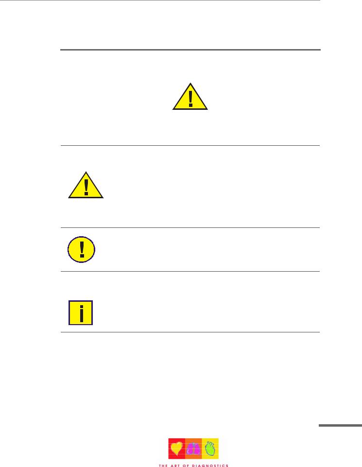
Symbols and Conventions Used in this Service handbook
The following words and symbols mark special messages throughout this guide.
General Warning. Text set off in this manner indicates that failure to follow directions could result in bodily harm or loss of life or failure to follow directions could result in damage to equipment or loss of information.
WARNING:
Specific Warning. Text set off in this manner indicates that failure to follow directions could result in bodily harm or loss of life.
CAUTION:
Text set off in this manner indicates that failure to follow directions could result in damage to equipment or loss of information.
NOTE:
Text set off in this manner presents clarifying information, specific instructions, commentary, sidelights, or interesting points of information.
xv
Article Number 2. 540 028
SCHILLER AG 2002

SCHILLER
AT-102 ECG Recorder Service Handbook
What's in this book
The service philosophy for the AT-102 is fault finding to module level. The purpose of this book is to provide all the information necessary to enable the service engineer to efficiently locate and replace a faulty module. This book assumes no detailed knowledge of the AT-102 but does require that the service engineer is familiar with standard workshop practices, and to have attended an AT102 service course. The book is divided into the following chapters:
Chapter 1 - Operating Elements
The purpose of this chapter is to provide an easy reference for all the main operator functions and to give a basic introduction to the AT-102 . This chapter gives details of the operator controls with the operation and function of each key briefly explained. The information in this chapter provides a background to the operating functions only. Complete operating information is provided in the SCHILLER AT-102 User Guide.
Chapter 2 - Functional Overview
This chapter provides a functional overview of the AT-102 . The description is supported by functional block diagrams.
Chapter 3 - Fault Diagnosis
This chapter provides a guide to locate a fault to module level. The diagnostics are presented in a logical sequence of fault finding algorithms and procedures. Illustrations are provided to support the text where needed.
Chapter 4 - Module Removal and Replacement
This chapter gives an overview of the physical construction of the AT-102 with the main physical attributes of the unit briefly described. The physical description is supported by illustrations showing the internal location of all modules. Removal and replacement instructions for all removable modules are also provided in this chapter. Each procedure is autonomous with details of tools, jumper settings, adjustments and settings or special requirements that are required before and after replacement. Functional checks that must be carried out after replacing a module are also provided.
xvi

AT-102 ECG Recorder Service Handbook |
Contents |
|
Chapter 5 -Adjustments
This chapter provides all adjustments and settings. Also detailed in this chapter are basic functional test procedures that can be performed to check the functioning of the unit.
Chapter 6 - Spare Parts
This chapter provides the part numbers and reordering information for all replaceable modules. Also included in this chapter are details of any special test equipment or special tools required for adjustment or fault finding procedures.
Chapter 7 - Technical Data
The full technical specification of the AT-102 is given in this chapter.
Annex A - Glossary
This chapter explains all the acronyms and signal titles used in this book and in the AT-102 circuit diagrams.
Annex B - Circuit Diagrams & Board layouts
The circuit diagrams and component layouts are provided for all boards. These details are provided for information only.
xvii
Article Number 2. 540 028
SCHILLER AG 2002

SCHILLER
AT-102 ECG Recorder Service Handbook
xviii

AT-102 ECG Service Handbook |
Section 1 |
|
Operating Elements |
Section 1
Operating Elements
This section contains an introduction to the AT-102 and an overview of all external connections. It also gives an overview of the operating philosophy of the AT-102 and an introduction to the basic functions of the unit. An overview of the system settings are given in this section - for full operating details and system setup see the AT-102 User Guide.
1.1
Article Number 2. 540 028
SCHILLER AG 2002

AT-102 Service Handbook
Introduction
The SCHILLER AT-102 is a 12-channel ECG unit designed to record, display, and analyse resting ECGs (exercise ECGs can also be recorded). The unit has been extensively researched to give an ergonomic, clear interface that`s easy to use without compromising functionality. The AT-102 has the following features:
Features
Alphanumeric keypad and dedicated soft key interface for easy, user friendly operation.
Storage and transmission facilities for recordings.
Excercise ECG with interface for control of digital ergometers and treadmills. (Option)
Integral full size thermal quality printer with various user defined print format options. External laser or deskjet printer (Option).
ECG Interpretation including measurements and average cycles with automatic and manual printout of the recording. (Option)
Spirometry (Option)
1.2
AT-102 ECG Service Handbook |
Section 1 |
|
Operating Elements |
Introduction
Operating Philosophy Overview
There are broadly four types of data display as follows
Data Acquisition and |
In this screen the real-time ECG is displayed. From this |
ECG Recording Screen |
screen a continuous printout can be initiated and/or an |
|
auto recording can be made. In auto mode 10 seconds of |
|
ECG data is analysed and averaged and the results given |
|
on a printout. The format and data of an auto mode printout |
|
is independent of the screen display. |
|
An auto mode recording can also be stored in the memory |
|
for later print or transmission. |
Memory Screen |
In this screen stored recordings can be accessed. |
Patient Data Screen |
Patient data entry via the keypad. |
Data Entry and Setup |
In these screens all system settings, resting and exercise |
|
ECG settings, and spiro settings are made. |
Initiating Functions or Tasks
Most functions and tasks are initiated by the 5 softkeys situated immediately below the LCD. The function of the softkeys varies according to the screen displayed and is displayed on the LCD immediately above the key itself.
During data acquisition, further dedicated function keys are provided to make an auto mode recording (START) and to stop a manual printout (STOP). The top line of the alphanumeric keypad, additionally enables direct settings of lead group, trace speed and sensitivity, filter on/off and other functions, for both the real-time display and (manual) printout.
1.3
Article Number 2. 540 028
SCHILLER AG 2002

AT-102 Service Handbook
Introduction
Main Components of the AT-102
1 |
2 |
3 |
4 |
5 |
1.Keypad and dedicated function keys
2.Patient cable connector
3.RS-232 for any of the following:
°connection of an ergo device
°connection of a spiro sensor
°connection of a modem or a PC for export of stored recordings
4.Softkey control
5.LCD Display.
1.4
AT-102 ECG Service Handbook |
Section 1 |
|
Operating Elements |
Introduction
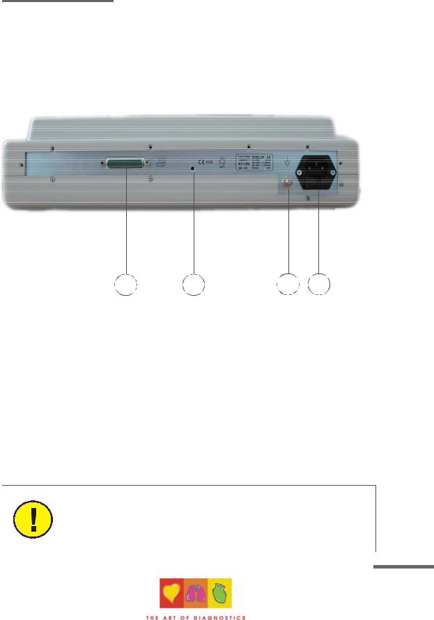
Back Panel
1 |
2 |
3 |
4 |
1.LPT connector for the connection of an external printer
2.Master Reset
3.Potential equalisation stud
4.Mains connector (with fuse below)
CAUTION:
All externally connected hardware must be approved by SCHILLER. Connection of any hardware not approved by SCHILLER is at the owner`s risk. The unit guarantee may also be invalid.
1.5
Article Number 2. 540 028
SCHILLER AG 2002

AT-102 Service Handbook
Introduction
Power Supply
The mains connection is on the rear of the unit.
The power supply voltage is set by the factory for 100-115V (nom. 110V) or 220-240V (nom. 230V) working. The setting is indicated by the indented metal strip on the fuse panel. Contact your dealer if the voltage needs to be changed.
Switching On and Off
The AT-102 is switched on with the green ON key and off with the red OFF key. These keys are situated on the top right of the keypad.
The mains indicator lamp on the keypad is always lit when the unit is connected to the mains supply.
The unit can either be operated from the mains supply or from the built-in rechargeable battery. The power source is indicated on the top line of
the LCD. When mains is connected a mains symbol is displayed. When the unit is running on battery power a battery symbol is displayed
Power Indicator symbol
The internal battery provides power for up to 3 hours. The Battery indicator blinks when the battery capacity is limited.
To recharge the battery, connect the apparatus to the mains supply by means of the supplied power cable. A totally discharged battery requires less than 15 hours to be fully recharged (60% in less than 3 hours, 90% in less than 7 hours). The unit can remain connected to the mains supply without damage to either the battery or the unit.
NOTE
When working from battery power, the unit is automatically switched off after 5 minutes (30 seconds if battery capacity is limited) if no key is pressed.
1.6
AT-102 ECG Service Handbook |
Section 1 |
|
Operating Elements |
Introduction
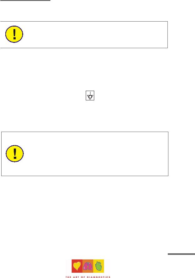
Changing a Mains Fuse
CAUTION
If it is necessary to change a fuse, always replace with the correct rating i.e. 2x200mAT for 230V, or 2x315mAT for 110V .
To change a fuse press the retaining lug in the middle of the fuse panel (situated below the
mains connector on the back panel). Remove the fuse panel and replace the fuse(s). Click
the fuse panel back in position.
Potential Equalisation
The potential equalisation stud at the rear of the unit can be used to equalise the ground
potential of the AT-102 to that of all mains powered equipment in the vicinity. Use the
hospital or building common ground.
CAUTION:
To avoid possible interference from the Ergometer when carrying out an exercise test, it is recommended that both the AT-102 and the Ergometer are connected to the same common ground.
To prevent the possibility of leakage current when an external printer is connected, always ensure that the mains lead, or the potential equalisation (next to the mains connector), is attached to the AT-102
A yellow/green ground cable is supplied as an option (Article number 2. 310 005).
1.7
Article Number 2. 540 028
SCHILLER AG 2002

AT-102 Service Handbook
Introduction
Keypad
1
2 |
|
|
|
3 |
|
|
4 |
5 |
6 |
7 |
8 |
9 |
10 |
11 |
12 |
13 |
14 |
15 |
17 |
16 |
1.8

AT-102 ECG Service Handbook |
Section 1 |
|
Operating Elements |
Introduction
1.Softkeys - the function of these keys changes depending on the screen displayed. The function of these keys is shown on the screen above the keys. If nothing is written above a softkey, it has no function for the current screen.
2.Auto Mode recording (in Auto mode 1).
Press the Function key (17) followed by the AUTO key (2) for auto mode 2.
3.STOP printout / confirm (new) setting
4.Open / Close paper tray (to replace thermal printing paper)
5.The top figures on the number keys `1` and `2 ` (designated < and >), change the lead group displayed on the screen, forward and backward resp.
6.Auto sensitivity key - automatically sets the ECG printout sensitivity ( in AUTO mode only) to the best setting for the signal strength (5mm/mV or 10mm/mV)
7.The top figures on the number keys designated 5, 10, and 20 set the sensitivity of the ECG both on the screen and on the (manual) printout. The sensitivity is 5, 10 or 20 mm / mV.
8.The top figures on the number keys designated 5/10, 25, and 50 set the speed of the ECG both on the screen and on the (manual) printout. The speed on the screen can only be set to 25 or 50 mm/s. The speed of the manual printout can be 5, 10, 25 or 50 mm/s. The 5 and 10 mm/s settings are both on the same key which toggles the two speeds.
9.Inserts a 1mV reference marker on the screen and printout. Recentres the trace.
10.Toggles the QRS beeper ON/ OFF
11.Myogram filter ON / OFF. The cutoff frequency can be user defined in `Setup`.
12.Delete last typed character.
13.Patient data key. Press this key to enter a new patient or modify the data for the current one.
NOTE:
The patient data screen, or the ECG screen is the first screen displayed on inital switch on. This is set for user preference in the system settings (See following).
14. ON / OFF Keys
15. Mains Indicator - lit when mains connected.
16. Press the function key (17) and the UP/DOWN arrows to adjust screen contrast. When entering patient data use the LEFT/RIGHT arrow keys to move the cursor in the data field. Use the UP/DOWN arrow keys to go up/down to the next data entry
17. Function Key (Fn). When pressed before another key, initiates the second function of that key.
For example, second letters on the keypad (è, é, ç, ø @ etc.), are entered by holding
the function key before pressing the letter key.
1.9
Article Number 2. 540 028
SCHILLER AG 2002

AT-102 Service Handbook
Introduction
LCD Screen
The display will vary according to the current task being carried out. In all screens however, the top and bottom lines always display the same information: the top line displays system information (time, patient, power source etc.,), and the bottom line always gives the softkey options.
The following is an example of a typical resting ECG screen.
3
1
4
5
6
7
8
9 10
2
Items 1, 2 and 3 are in the same position for all screens.
1.Top line - time, date, patient name, and current power source - mains ( ), or battery (
 ). When battery capacity is limited the battery symbol flashes.
2.Softkey designation. Pressing the key below the text carries out the function indicated. The options available will change according to the screen displayed.
3.Data acquisition area or data entry area.
1.10

AT-102 ECG Service Handbook |
Section 1 |
|
Operating Elements |
Introduction
Items 4 to 10 are specific for ECG acquisition only:
4.Current Heart Rate (averaged over 4 beats and refreshed every 2 seconds). The HR is also given on a manual printout. Note that with an auto mode printout the HR is averaged over the full 10 seconds of the recording.
5.Electrode connections - when a lead flashes it indicates that the electrode resistance is too high. The electrode(s) must be reapplied.
6.Sensitivity - 5, 10 or 20 mm/mV. Change the sensitivity with the keys 3 (auto), 4, 5 and 6. An `A` in this box indicates that automatic sensitivity is selected (auto mode printout only).
7.Speed - 25 or 50 mm/s. Change the speed with the keys 8 and 9.
8.Lead indication (leads currently displayed on the screen). Change the lead group with the < and > keys on the keypad.
9.Myogram Filter indication - 'Filter ON' or 'Filter OFF'. The filter is applied with the filter key.
Note: the frequency of the filter cutoff is defined in Section 4 Setup.
10.Area for system messages or instructions.
1.11
Article Number 2. 540 028
SCHILLER AG 2002

AT-102 Service Handbook
ECG Settings
The AT-102 ECG and system settings are entered by selecting 'setup' from the initial
screen:
The following pages detail the programmable ECG parameters.
NOTE:
In units where the interpretation option is not installed, interpretation statements, cannot be displayed.
1.12
 Loading...