


AT-10 plus
12 Channel ECG Unit
2.510536 rev.: c *2.510536* |
User Guide |
Art. no.: |
|
AT-10 plus
12 Channel ECG Unit
2.510536 rev.: c *2.510536* |
User Guide |
Art. no.: |
|

Sales and Service Information
The SCHILLER sales and service centre network is world-wide. For the address of your local distributor, contact your nearest SCHILLER subsidiary. In case of difficulty a complete list of all distributors and subsidiaries is provided on our internet site:
www.schiller.ch
Sales information can also be obtained from: sales@schiller.ch
Address Headquarters
SCHILLER AG |
Tel: +41 (0) 41 766 42 42 |
Altgasse 68 |
Fax: +41 (0) 41 761 08 80 |
CH-6341 Baar |
sales@schiller.ch |
Switzerland |
www.schiller.ch |
Article No: 2.510536 rev.: c
Issue date: 19.07.05

Art. no.: 2.510536 rev.: c
AT-10 plus |
User Guide |
|
|
Contents |
|
|
1 |
Safety Notes .............................................. |
7 |
1.1 |
Responsibility of the User .................................................. |
7 |
1.2 |
Intended Use ........................................................................ |
7 |
1.3 |
Organisational Measures..................................................... |
8 |
1.4 |
Safety-conscious Operation................................................ |
8 |
1.5 |
Safety Facilities .................................................................... |
8 |
1.6 |
Operation with other Devices.............................................. |
9 |
1.7 |
Maintenance.......................................................................... |
9 |
1.8 |
Safety Symbols and Pictograms....................................... |
10 |
1.8.1 Symbols used in this document ....................................................... |
10 |
|
1.8.2 Symbols used on the devicei ........................................................... |
11 |
|
1.9 |
Terms of Warranty.............................................................. |
12 |
2 |
Introduction ............................................ |
13 |
2.1 |
Features............................................................................... |
13 |
2.1.1 |
Standard........................................................................................... |
13 |
2.1.2 |
Options............................................................................................. |
13 |
2.1.3 |
Connectors....................................................................................... |
13 |
2.2 |
Operating Philosophy ........................................................ |
14 |
2.2.1 |
User and User Rights....................................................................... |
14 |
2.3 |
Main Components of the AT-10 plus ............................... |
14 |
2.3.1 |
LCD Screen...................................................................................... |
15 |
2.3.2 |
Keypad ............................................................................................. |
16 |
2.4 |
External Connections......................................................... |
18 |
2.4.1 |
Back Panel ....................................................................................... |
18 |
2.4.2 |
Side Panel........................................................................................ |
19 |
3 |
Operation ................................................ |
20 |
3.1 |
Start-up and Initial Preparation ......................................... |
20 |
3.1.1 |
Location............................................................................................ |
20 |
3.1.2Connection of External Cable Assemblies and Ancillary Equipment 20
3.1.3 |
Potential Equalisation....................................................................... |
20 |
3.1.4 Switching ON and OFF .................................................................... |
21 |
|
3.1.5 Power Supply and Battery Operation............................................... |
21 |
|
3.1.6 Isolating the Mains Supply ............................................................... |
21 |
|
3.1.7 System and ECG Settings ............................................................... |
21 |
|
3.2 |
Changing the Printing Paper ............................................ |
22 |
3.3 |
Selecting Menu Options using the Arrow Keys............... |
23 |
3.4 |
Entering Patient Data ......................................................... |
24 |
Page 3

|
|
AT-10 plus |
4 |
Electrode Placement .............................. |
25 |
4.1 |
Electrode Identification and Colour Code ........................ |
25 |
4.2 |
Standard 10-lead Resting ECG.......................................... |
26 |
4.2.1 |
Placing the Electrodes ..................................................................... |
26 |
4.2.2 |
Exercise ECG .................................................................................. |
27 |
4.3 |
Further Lead Combinations............................................... |
28 |
4.3.1 |
Nehb Leads...................................................................................... |
28 |
4.3.2 |
Additional Leads .............................................................................. |
29 |
4.4 |
Skin/Electrode Resistance................................................. |
30 |
4.4.1 |
Electrode and Patient Cable Check (Lead Test).............................. |
30 |
4.5 |
Lead Sequence ................................................................... |
31 |
4.5.1 Setting Standard, Cabrera or User Defined Lead Sequence........... |
31 |
|
5 |
Resting ECG ............................................ |
32 |
5.1 |
Procedural Flow Diagram .................................................. |
33 |
5.2 |
Automatic Mode Recording ............................................... |
34 |
5.2.1 The Auto Mode Printout ................................................................... |
34 |
|
5.3 |
Manual Mode (Rhythm Printout) Recording..................... |
35 |
5.3.1 The Manual Mode Printout............................................................... |
35 |
|
5.4 |
Rhythm Mode Recording ................................................... |
36 |
5.4.1 Taking a Rhythm Mode Recording .................................................. |
36 |
|
5.4.2 |
The Rhythm Printout ........................................................................ |
36 |
5.5 |
Recording External Signals (Using the DC Inputs) ......... |
37 |
5.5.1 |
Procedure ........................................................................................ |
37 |
5.6 |
Changing Lead Group, Amplitude and Speed ................. |
38 |
5.6.1 |
On the Screen.................................................................................. |
38 |
5.6.2 |
On the Manual Printout .................................................................... |
38 |
5.6.3 Re-centring the trace, 1mV reference pulse .................................... |
39 |
|
5.6.4 |
Myogram Filter ................................................................................. |
39 |
5.6.5 |
Other Filters ..................................................................................... |
39 |
5.6.6 |
Auto Sensitivity ................................................................................ |
39 |
5.7 |
ECG Settings....................................................................... |
40 |
5.7.1 Table of ECG Options and Settings................................................. |
40 |
|
6 |
Exercise ECG .......................................... |
44 |
6.1 |
Exercise Flow Diagram ...................................................... |
45 |
6.2 |
Test Procedure Overview................................................... |
46 |
6.3 |
During the Test ................................................................... |
47 |
6.3.1 |
Entering Symptoms.......................................................................... |
50 |
6.3.2 |
NIBP................................................................................................. |
51 |
6.3.3 Controlling the Ergometer during the Test ....................................... |
51 |
|
6.4 |
At the End of the Test......................................................... |
52 |
6.5 |
Exercise Settings................................................................ |
53 |
6.5.1 |
General Exercise Settings ............................................................... |
53 |
6.5.2 |
Table of Exercise Settings and Options........................................... |
53 |
6.6 |
Defining a Protocol............................................................. |
55 |
6.6.1 |
Standard Treadmill Protocols........................................................... |
57 |
6.6.2 |
Bruce................................................................................................ |
57 |
6.6.3 |
Balke ................................................................................................ |
57 |
6.6.4 |
Naughton ......................................................................................... |
57 |
6.6.5 |
Ellestad ............................................................................................ |
58 |
6.6.6 |
Cooper ............................................................................................. |
58 |
Art. no.: 2.510536 rev.: c
Page 4

Art. no.: 2.510536 rev.: c
AT-10 plus User Guide
7 |
Memory and Transmission .................... |
59 |
7.1 |
Memory................................................................................ |
59 |
7.1.1 |
Transmitting, Printing and Deleting Stored Recordings ................... |
60 |
7.2 |
Storing a Recording ........................................................... |
60 |
7.2.1 |
Automatic Storage............................................................................ |
60 |
7.2.2 |
Manual Storage................................................................................ |
60 |
7.3 |
Transmitting/ Receiving Data ............................................ |
60 |
7.3.1 |
Setup................................................................................................ |
61 |
7.3.2 |
Automatic Transmission................................................................... |
62 |
7.3.3 |
Manual Transmission ....................................................................... |
62 |
7.3.4 Receiving Data from the PC............................................................. |
62 |
|
8 |
General and System Settings ................ |
63 |
8.1 |
System Settings.................................................................. |
63 |
8.2 |
Table of Unit Settings......................................................... |
63 |
8.2.1 |
Communication settings................................................................... |
67 |
9 |
Unit Maintenance .................................... |
69 |
9.1 |
Visual Inspection ................................................................ |
69 |
9.2 |
Cleaning the Casing and Cable Assemblies.................... |
70 |
9.3 |
Cleaning the Thermal Print Head ...................................... |
70 |
9.4 |
Battery Maintenance .......................................................... |
71 |
9.4.1 |
Charging the battery......................................................................... |
71 |
9.4.2 |
Battery disposal................................................................................ |
71 |
9.5 |
Changing the fuse and mains voltage.............................. |
72 |
9.5.1 |
Fuse types........................................................................................ |
72 |
9.5.2 |
Changing a fuse ............................................................................... |
72 |
9.5.3 |
Changing the mains voltage............................................................. |
72 |
10 |
Trouble Shooting .................................... |
73 |
10.1 |
Trouble Shooting Table ..................................................... |
73 |
10.2 |
Accessories and Disposables........................................... |
74 |
11 |
Technical Data ........................................ |
75 |
11.1 |
System................................................................................. |
75 |
11.2 |
ECG...................................................................................... |
76 |
11.3 |
Safety Standards ................................................................ |
78 |
12 |
Index ........................................................ |
79 |
Page 5

AT-10 plus
Art. no.: 2.510536 rev.: c
Page 6
Art. no.: 2.510536 rev.: c
AT-10 plus |
User Guide |
Safety Notes |
1 |
|
Responsibility of the User |
1.1 |
|||
|
|
|
|
|
1 Safety Notes
1.1Responsibility of the User
! This device must only be used by qualified doctors or trained medical personnel.
! The numerical and graphical results and any interpretation given must be examined with respect to the overall clinical condition of the patient and the general recorded data quality.
!The indications given by this equipment are not a substitute for regular checking of vital functions.
!Specify the competencies of the personnel for operation and repair.
!Ensure that personnel have read and understood these operating instructions. In particular this section “safety notes" must be read and understood.
!Damaged or missing components must be replaced immediately.
The operator is responsible for compliance with all applicable accident prevention regulations and safety regulations.
1.2Intended Use
! The AT-10 plus is a 12-channel, ECG device used for the recording, analysis and evaluation of ECG Recordings. Recordings made with the AT-10 plus can be used as a diagnostic aid for heart function and heart conditions. It is designed for indoor use and can be used for all patients of both sexes, all races, and all ages.
!The diagnostic applications for which the AT-10 plus is intended is in the diagnosis of cardiac abnormalities in the general population, detecting acute miocardial ischemia, and infarction in chest pain patients, etc.
!The AT-10 plus is intended for use in hospitals, cardiological units, out-patient clinical units, and general physicians offices.
!The AT-10 plus includes a low sensitivity setting. Low sensitivity will suppress certain non-specific ECG diagnoses; this can be used for screening highspecificity program intended for low-risk patients. The high sensitivity setting is used for detecting cardiac abnormalities in all and high risk patients including those taking thrombosis medication.
!There is no danger for patients with pacemaker.
!Only operate the device in accordance with the specified technical data.
!The device is not designed for sterile use nor is it designed for outdoor use.
!Do not use this unit in areas where there is any danger of explosion or in the presence of flammable gases such as anaesthetic agents.
!
 !
!
 This unit is CF classified and defibrillation protected only when the original patient cable is used. However, as a safety precaution when possible, remove electrodes before defibrillation.
!This product is not designed for internal use.This product is not designed for direct cardiac application.
Page 7
1 |
Safety Notes |
AT-10 plus |
|
1.3 |
Organisational Measures |
||
|
|
|
|
1.3Organisational Measures
! Before using the unit, ensure that an introduction regarding the unit functions and the safety precautions has been provided by a medical product representative.
! Keep these operating instructions in an accessible place for reference when required. Make sure that they are always complete and legible.
!Observe the operating instructions and maintenance instructions.
!These operating instructions do not override any statutory or local regulations, or procedures for the prevention of accidents and environmental protection.
1.4Safety-conscious Operation
! Make sure that the staff have read and understood the operating instructions - particularly this "Safety Notes" section.
! Do not touch the unit casing during defibrillation.
!To ensure patient safety, none of the electrodes including the neutral electrode, nor the patient or any person with simultaneous patient contact, must come in contact with conductive parts, even when these are earthed.
!Immediately report any changes that impair safety (including operating behaviour) to the person responsible.
!Do not place any liquids on the unit. If liquid should be spilled over the device, immediately disconnect the device from the mains and wipe it. The device must be serviced before reusing.
!Only connect the original SCHILLER patient cable to the patient socket.
1.5Safety Facilities
! Operating the device without the correctly rated fuse, or with defective cables, constitutes a danger to life. Therefore:
– Do not operate the unit if the earth connection is suspect or if the mains lead is damaged or suspected of being damaged.
–Damaged cable connections and connectors must be replaced immediately.
–The electrical safety devices, such as fuses, must not be altered.
–Ruptured fuses must only be replaced with the same type and rating as the original.
Art. no.: 2.510536 rev.: c
Page 8
AT-10 plus |
User Guide |
Safety Notes |
1 |
|
Operation with other Devices |
1.6 |
|||
|
|
|
|
|
1.6Operation with other Devices
! Only use accessories and other parts recommended or supplied by SCHILLER AG. Use of other than recommended or supplied parts may result in injury, inaccurate information and/or damage to the unit.
!Ancillary equipment connected to any analogue and/or digital interface of the unit must be certified according to the respective IEC standards (e.g. IEC/EN 60950 for data processing equipment and IEC/EN 60601-1 for medical equipment). Furthermore all configurations shall comply with the valid version of the system standard IEC/EN 60601-1-1. Everybody who connects additional equipment to the signal input part or signal output part configures a medical system, and is therefore responsible that the system complies with the requirements of the valid version of the system standard IEC/EN 60601-1-1. If in doubt, consult the technical service department or your local representative.
!Any other equipment used with the patient must use the same common earth as the AT-10 plus.
!Precautions must be observed when using high frequency devices. Use the special high frequency SCHILLER patient cable to avoid possible signal interference during ECG acquisition.
!There is no danger when using the ECG unit simultaneously with electrical stimulation equipment. However, the stimulation units should only be used at a sufficient distance from the electrodes. If in doubt, the patient should be disconnected from the devic6e.
!If the patient cable should become defective after defibrillation, an electrode becomes displaced, or an electrode resistance is too high, a lead-off indication is displayed in the upper right part of the screen and an acoustic alarm given.
!If the device is a part of a medical system, the original SCHILLER patient cable must only be used with, and connected to, the patient connector on the AT-10 plus.
1.7Maintenance
! Danger of electric shock! Do not open the device. No serviceable parts inside. Refer servicing to qualified technician authorised by SCHILLER only.
! Before cleaning and to isolate the mains power supply, switch the unit off and disconnect it from the mains by removing the plug.
!Do not use high temperature sterilisation processes (such as autoclaving). Do not use E-beam or gamma radiation sterilisation.
!Do not use solvent or abrasive cleaners on either the unit or cable assemblies.
!Do not, under any circumstances, immerse the unit or cable assemblies in liquid.
Art. no.: 2.510536 rev.: c
Page 9
1 |
Safety Notes |
AT-10 plus |
|
1.8 |
Safety Symbols and Pictograms |
||
|
|
|
|
1.8Safety Symbols and Pictograms
1.8.1Symbols used in this document
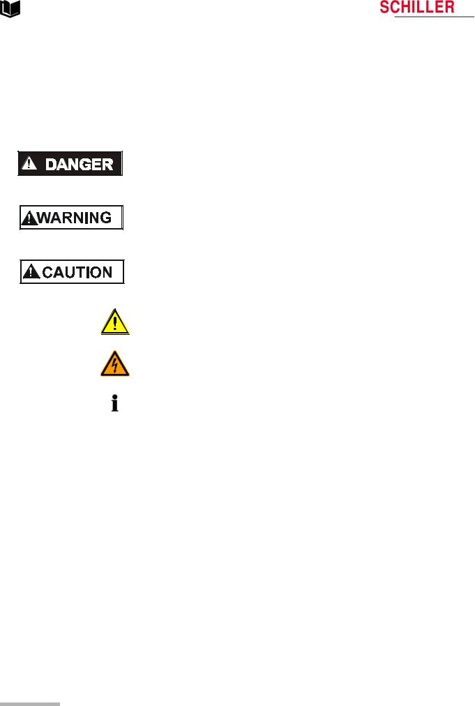
The safety level is classified according ANSI Z535.4. The following overview shows the used safety symbols and pictograms used in this manual.
For a direct danger which could lead to severe personal injury or to death.
For a possibly dangerous situation, which could lead to serious bodily injury or to death.
For a possibly dangerous situation which could lead to personal injury. This symbol is also used to indicate possible damage to equipment.
For general safety notes as listed in this chapter.
Used for electrical dangers, warnings and other notes in regarding operation with electricity.
Note For possibly dangerous situations, which could lead to damage to property or system failure. Important or helpful user information.
Reference to other guidelines.
Art. no.: 2.510536 rev.: c
Page 10
AT-10 plus |
User Guide |
Safety Notes |
1 |
|
Safety Symbols and Pictograms |
1.8 |
|||
|
|
|
|
|
1.8.2Symbols used on the devicei
Potential equalization
CF symbol. This unit is classified safe for internal and external use. However, It is only defibrillation protected when used with the original SCHILLER patient cable.
Symbol for the recognition of electrical and electronic equipment
Equipment/components and accessories no longer required must be disposed of in a municipally approved collection point or recycling centre. Alternatively, you can return the equipment to your supplier or SCHILLER AG for disposal. Improper disposal can harm the environment and human health.
The unit/component can be recycled.
Notified body of the CE certification (TÜV P.S.).
Attention: Consult accompanying documents.
Art. no.: 2.510536 rev.: c
Page 11

1 |
Safety Notes |
AT-10 plus |
|
1.9 |
Terms of Warranty |
||
|
|
|
|
1.9Terms of Warranty
The SCHILLER AT-10 plus is warranted against defects in material and manufacture for the duration of one year (as from date of purchase). Excluded from this guarantee is damage caused by an accident or as a result of improper handling. The warranty entitles free replacement of the defective part. Any liability for subsequent damage is excluded. The warranty is void if unauthorised or unqualified persons attempt to make repairs.
In case of a defect, send the apparatus to your dealer or directly to the manufacturer. The manufacturer can only be held responsible for the safety, reliability, and performance of the apparatus if:
•assembly operations, extensions, readjustments, modifications, or repairs are carried out by persons authorized by him, and
•the SCHILLER AT-10 plus and approved attached equipment is used in accordance with the manufacturers instructions.
There are no express or implied warranties which extend beyond the warranties hereinabove set forth. SCHILLER makes no warranty of merchantability or fitness for a particular purpose with respect to the product or parts thereof.
This equipment has been tested and found to comply with the limits for a class A digital device, pursuant to both Part 15 of the FCC (Federal Communications Commission) rules and the radio interference regulations of the Canadian Department of Communications. These limits are designed to provide reasonable protection against harmful interference when the equipment is operated in a commercial environment. This equipment generates, uses and can radiate radio frequency energy and, if not installed and used in accordance with this instruction manual, may cause harmful interference to radio communications. Operation of this equipment in a residential area is likely to cause harmful interference in which case the user will be required to correct the interference at his own expense.
Art. no.: 2.510536 rev.: c
Page 12

Art. no.: 2.510536 rev.: c
AT-10 plus |
User Guide |
Introduction |
2 |
|
Features |
2.1 |
|||
|
|
|
|
|
2 Introduction
2.1Features
The SCHILLER AT-10 plus is a 12-channel ECG unit designed to record, display, and measure resting ECGs. The AT-10 plus has the following features:
2.1.1Standard
•Pacemaker Detection
•Manual (real time) mode - (leads, speed and amplitude can be changed as required)
•Auto mode with user defined presentation formats
•Rhythm recording with user defined formats (planned)
•Measurements
2.1.2Options
•Interpretation
•Thrombolysis (with C version (interpretation) only)
•Stress testing with standard test protocols and user defined protocols, analysis program with ST measurement, average complexes and trends (EXEC)
•Extended Memory (planned option)
•Full disclosure of all 12 leads (planned option)
•Spirometry (planned option)
•Pacemaker measurement (planned option)
•Heart rate variability (planned option)
•Late potential analysis (planned option)
2.1.3Connectors
•VGA interface for the connection of an external monitor
•DC input connector for on-screen presentation or printout of external signals
•DC Output connector for output of recorded signals
•RS-232 interfaces for control of digital treadmills and digital bikes
•Analogue interface for control of an analog ergometer
•RS-232 interface for a spiro flow sensor or data transmission / reception
Schiller Communication Module (SCM)
•Analogue Modem connecter (with optional internal modem)
•RS-232 interface for external blood pressure unit.
•RJ-45 ethernet connector (network)
•Two USB connectors
•SDCARD slot (with 64MB SD Card) for removable storage of recordings
Page 13
2 |
Introduction |
AT-10 plus |
|
2.2 |
Operating Philosophy |
||
|
|
|
|
2.2 |
Operating Philosophy |
2.2.1 |
User and User Rights |
|
There are two user level as follows: |
Physician / Nurse |
The Physician / Nurse level is the default setting and is entered as soon as the unit is |
|
switched on. At this level the user can: |
|
• define and edit patient data |
|
• take resting and exercise ECGs |
|
• enter and edit patient data |
|
• view and validate recordings |
|
• access, send, receive and store recordings |
|
• define all general and medical settings |
Administrator / Service |
The administrator level allows access to all ‘technical‘ settings including extra system |
|
screens, test screens, software updates, etc., and is accessed by a code. Details are |
|
given in the service handbook. |
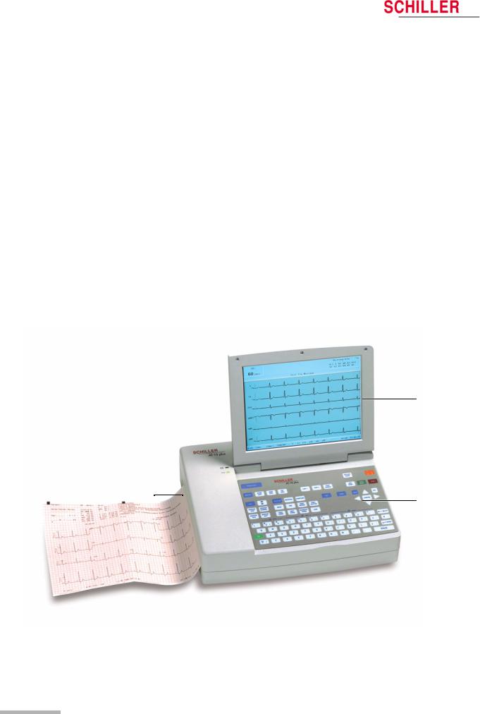
2.3 Main Components of the AT-10 plus
1
2 |
3 |
|
Art. no.: 2.510536 rev.: c
(1)LCD screen.
(2)Integrated thermal printer and paper tray.
(3)Water resistant keyboard.
Page 14
AT-10 plus |
User Guide |
Introduction |
2 |
|
Main Components of the AT-10 plus |
2.3 |
|||
|
|
|
|
|
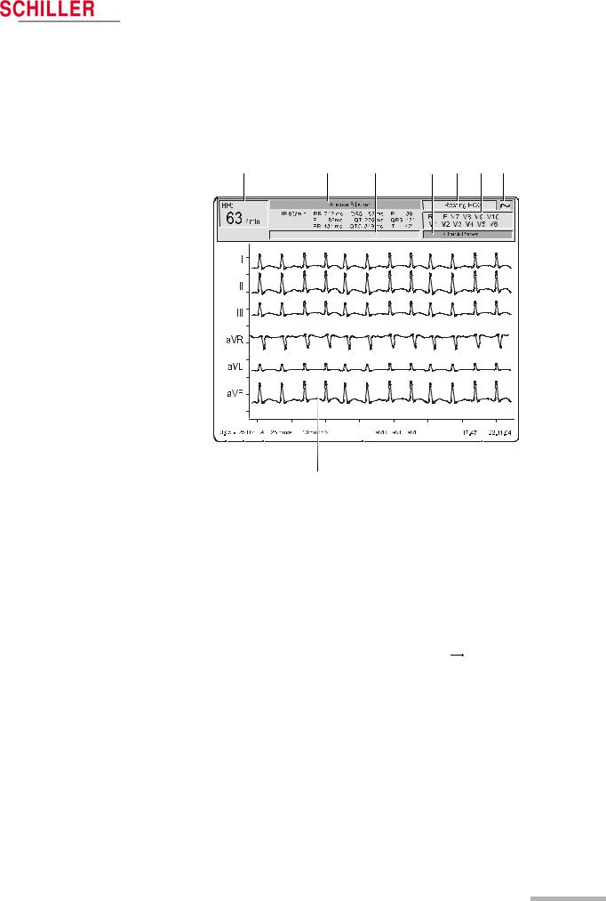
2.3.1LCD Screen
The display will vary according to the current task being carried out. In all screens however, the top, middle and bottom areas always display the same information groups. The following is an example of a typical resting ECG screen (for the exercise screen see page 27).
1 |
2 |
3 |
4 |
5 |
6 |
7 |
Art. no.: 2.510536 rev.: c
|
|
|
|
|
|
|
|
|
|
|
|
|
|
|
|
|
|
|
|
|
|
|
|
|
|
|
|
|
|
|
|
|
|
|
|
|
|
|
|
|
|
|
|
|
|
|
|
|
|
|
|
|
|
8 |
9 |
10 |
11 |
12 |
|
13 |
|||||||||||
(1)The heart rate (HR) - averaged over the last 4 beats.
(2)The patient name - below is the last auto mode recording intervals (if an auto mode recording has been taken).
(3)Message field - this area displays any status messages.
(4)Message Field - this area displays technical and system error messages.
(5)Current mode of operation (resting, stress, spiro).
(6)Electrode lead status - when an electrode indication flashes (an audible indication is also given), it indicates that the electrode resistance is too high. The electrode(s) must be re-applied - see page 30.
(7)Current power source - mains (~), or battery ( 
 ) - see page 21.
(8)Selected baseline frequency (0.05, 0.15, 0.30, or 0.60 Hz) - see page 40.
(9)Myogram filter cut-off frequency (25Hz, 35Hz or 150Hz (off)) - see page 39.
(10)Auto sensitivity reduction on (‘A‘ in box), or off (box empty) - to help reduce overlapping traces - see page 40.
(11)The central section of the screen displays the measured ECG traces.
(12)Manual Print settings - see page 35.
–speed in mm/s
–sensitivity in mm/mV
–selected leads
(13)System time and date.
Page 15

2 |
Introduction |
AT-10 plus |
|
2.3 |
Main Components of the AT-10 plus |
||
|
|
|
|
2.3.2 |
Keypad |
|
|
4 |
|
6 |
7 |
|
|
|
|
|
|
5 |
|
3 |
|
|
|
2 |
|
|
|
|
9 |
8 |
|
1 |
|
|
|
The keyboard is divided into the following functional areas:
(1)Alphanumeric and Dual Purpose Keys. The numerical keys are dual purpose as follows:
–Key 1 - switch myogram filter on or off
–The following keys change the speed, amplitude and lead group during manual printing:
–Key 2 and 3 - changes to next / previous lead group
–Key 4 to 7 - printout speed
–Keys 8 to ‘-‘ - printout Amplitude (sensitivity)
(2)Display, ECG and Stress ECG Function Keys:
•Display and ECG Keys
– ECG key - select ECG menu settings
– Monitor Lead key - display next lead group
– Monitor Channel key - change the number of leads displayed
– Monitor mm/s key - toggle display speed
– Monitor mmV key - toggle display sensitivity
– Cal key - reset ECG signal to baseline and insert calibration signal on the screen or on the printout
Page 16
Art. no.: 2.510536 rev.: c

Art. no.: 2.510536 rev.: c
AT-10 plus |
User Guide |
Introduction |
2 |
|
Main Components of the AT-10 plus |
2.3 |
|||
|
|
|
|
|
•Exercise Keys
–Exercise key - exercise ECG settings and function
–Protocol key - display/select/ edit exercise protocols
–Symptoms key - manual input of symptoms
–Begin key - start exercise test (beginning of warm-up phase) according to protocol set
–End key - stop exercise test (start of recovery phase)
–Print Report key - print final report (end of recovery phase)
–Print Rhythm key - print rhythm strip
–Hold Stage key - hold current stage
–Next Stage key - switch to next stage
–Interrupt Stage key - interrupts the test i.e. releases load on bike/stops treadmill - this function can be used, for example, to administer medication - when this key is again pressed, the test resumes from the same position
–Load key - overwrite protocol and define load
(3) Memory, Storage and transmission Keys:
–Memory key - gives access to the stored recordings.
–Store Data key - initiates data storage to internal memory of the current recording - the location where the recording is stored in defined in the system settings.
–Send Data key - initiates transmission over the defined interface of the current recording - the location where the recording is sent is defined in system settings
–Get Data key - initiates data reception from another location - the location from where the data is received is defined in the system settings
(4)Patient Data key - Input of patient data
(5)Direct function keys including:
–Print Screen key - print the displayed screen
–Copy 1 and Copy 2 keys - print a copy of current recording in format 1 or format 2
–Man Start key - imitate real time printout
–Auto Start key - take auto recording
–Stop key - stop real time printout / advance paper to beginning of new page
(6)Replace Paper key - extend or retract the paper tray for paper replacement
(7)On/Off key - switch the unit on or off
(8)Menu navigation keys including:
–Menu key - give access to system settings
–Confirm key - confirm current / displayed setting
–Left arrow key - move cursor to the left / select next menu option
–Right arrow key - move cursor to the right / select previous menu option
–Up arrow key - move cursor or menu bar up
–Down arrow key - move cursor or menu bar down
(9) Further Function Keys for:
–NIPB key - enter non-invasive blood pressure measurements
–SPIRO key - spirometry program (requires spiro sensor connected to the spiro RS-232 interface)
Page 17

2 |
Introduction |
AT-10 plus |
|
2.4 |
External Connections |
||
|
|
|
|
2.4External Connections
! All externally connected hardware must be approved by SCHILLER. Connection of any hardware not approved by SCHILLER is at the owner‘s risk. The unit guarantee may also be invalid.
2.4.1Back Panel
1 |
2 |
3 |
4 |
5 |
6 |
7 |
8 |
9 |
10 |
11 |
(1)RS-232 connector for Treadmill.
(2)RS-232 connector for Ergometer.
(3)Potential equalisation stud. The potential equalisation stud is used to equalise the ground potential of the unit to that of any nearby mains powered equipment. Use the hospital or building common ground for all mains powered units.
!If an external printer, monitor or ergo device is connected to the AT-10 plus, the potential equalisation stud must be connected to common ground when the AT10 plus is working on battery power i.e. when the mains lead (with grounding lead) is not connected to the unit - see page 20.
(4)Mains connector and fuse box (fuses: 2 x T 160 mA / 250 V).
(5)VGA connector for external monitor. Note that before an external monitor can be used, the VGA output must be enabled in system settings, see page 63.
The following connectors are situated on the communications module.
(6)RJ-45 Ethernet LAN connector (Local Area Network).
(7)USB connector for an external printer.
(8)RS-232 for an external BP unit.
(9)SD card slot for (removable) data storage (64MB).
(10)USB connector.
(11)RJ-11 telephone connector (with optional internal modem).
Art. no.: 2.510536 rev.: c
Page 18

AT-10 plus |
User Guide |
Introduction |
2 |
|
External Connections |
2.4 |
|||
|
|
|
|
|
2.4.2Side Panel
|
|
|
|
|
|
|
|
|
|
|
|
|
|
|
|
|
|
|
|
|
|
|
|
|
|
|
1 |
2 |
3 |
4 |
5 |
||||
(1) EKG/ECG patient cable input socket.
• The patient cable and connector is CF 


 rated, that is fully floating and isolated, defibrillation protected, suitable for intra-cardiac application.
•The unit is only CF rated and defibrillation protected if used with the original SCHILER patient cable.
(2) The RS-232 connector is used for
–connecting a pneumotach sensor (SP-250/SP-260) for pulmonary function testing.
–connecting a PC or modem for data transfer.
(3)DC input DCIN 1, 0.5 V/cm.
(4)DC output DCOUT, 0.5 V/cm.
(5)ERGO connector for connection of analogue ergometers.
Art. no.: 2.510536 rev.: c
Page 19
3 |
Operation |
AT-10 plus |
|
3.1 |
Start-up and Initial Preparation |
||
|
|
|
|
3 Operation
3.1Start-up and Initial Preparation
! Danger of electrical shock. Do not operate the unit if the earth connection is suspect or if the mains lead is damaged or suspected of being damaged.
3.1.1Location
•Do not keep or operate the unit in a wet, moist, or dusty environment. Avoid exposure to direct sunlight or heat from other sources.
•Do not allow the unit to come into contact with acidic vapours or liquids.
•The AT-10 plus should not be placed in the vicinity of X-ray or diathermy units, large transformers or electric motors. It must also be positioned at least one meter from the mains supply.
3.1.2Connection of External Cable Assemblies and Ancillary Equipment
1.Check the voltage setting (115V or 230V) - see page 72.
2.Connect the power cable at the rear of the unit. The Mains indicator lamp is lit. Leave the AT-10 plus connected to the mains for 7 hours to fully charge the battery - see page 21.
3.Connect the patient cable (side panel).
4.Connect any ancillary and optional equipment - see page 18. These may include the following:
–Ergometer (analogue or digital) for exercise testing
–Blood pressure unit
–Spiro sensor (for spirometry)
–External monitor
–Network cable
–External printer
3.1.3Potential Equalisation
The potential equalisation stud at the rear of the unit is used to equalise the ground potential of the AT-10 plus to that of all mains powered equipment in the vicinity. Use the hospital or building common ground. A yellow/green ground cable is supplied as an option (Article number 2. 310 005).
To avoid possible interference from the ergometer when carrying out an exercise test, it is recommended that both the AT-10 plus and the ergometer are connected to the same common ground.
! To prevent the possibility of leakage current when an external printer, external monitor, or ergo device is connected, always ensure that the mains lead (with earth grounding connection), and / or the potential equalisation, is attached to the AT-10 plus.
Art. no.: 2.510536 rev.: c
Page 20
Art. no.: 2.510536 rev.: c
AT-10 plus |
User Guide |
Operation |
3 |
|
Start-up and Initial Preparation |
3.1 |
|||
|
|
|
|
|
3.1.4Switching ON and OFF
The unit is switched on and off with the On / Off key.
3.1.5Power Supply and Battery Operation
The unit can be operated either from the mains supply or from the built-in rechargeable battery. The power source is indicated on the top line of the LCD and a mains and battery indicator on the unit. The mains indicator lamp is lit all the time the unit is connected to the mains supply. The mains symbol is also displayed in the top right corner of the screen when the unit is switched on.
Mains and battery LED Indicators
The LED indicators on the unit casing indicate the power operation as follows:
|
|
|
Function |
|
Battery LED |
|
Mains LED |
||||||
|
|
|
|
|
|
|
|
|
|
|
|
|
|
|
|
|
|
|
|
|
|
|
|
|
|
|
|
|
|
|
Mains Connected: |
|
|
|
|
|
|
|
|
|
|
|
|
|
Battery Charging |
• |
On |
• |
On |
||||||
|
|
|
Battery Full |
• |
Off |
• |
On |
||||||
|
|
|
Battery Working: |
|
|
|
|
|
|
|
|
|
|
|
|
|
Battery Capacity OK |
• |
On |
• |
Off |
||||||
|
|
|
Battery Capacity Limited (reconnect mains) |
• |
Blinking |
• |
Off |
||||||
|
|
|
Battery Capacity |
|
|
|
|
|
|
|
|
|
|
|
|
Full |
The internal battery provides power for up to four hours. When the unit is running on |
||||||||||
|
|
battery power a battery symbol replaces the mains symbol and indicates the battery |
|||||||||||
|
|
Half full |
|||||||||||
|
|
status. When the battery is full, the symbol is solid. |
|
|
|
|
|
|
|
|
|
||
|
|
|
|
|
|
|
|
|
|
|
|||
Empty
The battery is charged when the unit is connected to the mains supply. The unit can remain connected to the mains supply without damage to either the battery or the unit.
3.1.6Isolating the Mains Supply
To isolate the power supply, remove the mains plug from the wall socket.
3.1.7System and ECG Settings
•The System Settings (time, date, user ID, etc.), and other general settings (macros, ergometer, etc.), are found in the System Settings section - see page 63.
•Resting ECG settings (auto format, user defined leads, print options, lead test, QRS beep, interpretation, rhythm lead definition, etc.), are found in the Resting ECG Section, see page 40.
•Exercise settings (Heart rate target, protocol HR target, treadmill settings, recovery settings etc.) are found in the Exercise Section - see page 53.
Page 21
3 |
Operation |
AT-10 plus |
|
3.2 |
Changing the Printing Paper |
||
|
|
|
|
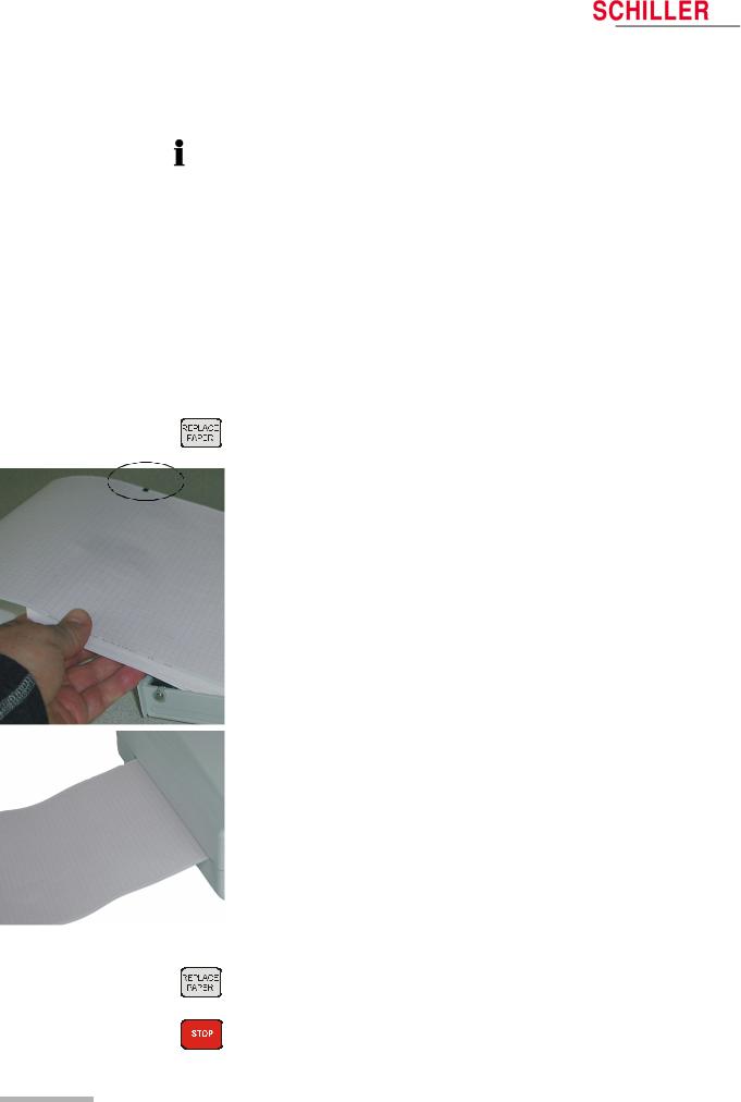
3.2Changing the Printing Paper
Important
The device is delivered without printing paper installed. The thermo-paper is sensitive to heat, humidity and chemical vapours.The following points apply to both storage, and when archiving the results.
•Before use, keep the paper in its original cardboard cover. Do not remove the cardboard cover until the paper is to be used.
•Store in a cool, dark and dry area.
•Do not store near chemicals e.g. sterilisation liquids.
•In particular do not store in a plastic cover.
•Certain glues can react with the paper - do not attach the printout onto a mounting sheet with glue.
SCHILLER can only guarantee perfect printouts when SCHILLER original chart paper or chart paper of the same quality is used.
1. Press the Replace Paper key to open the paper tray (remove any remaining paper from the paper tray if replacing paper.
2.Place a new paper pack into the paper tray with the printed (grid) side facing upwards and the black paper mark to the top of the unit.
3.Place the beginning of the paper over the black paper roller on the paper tray cover.
Art. no.: 2.510536 rev.: c
4.Press the Replace Paper key to return the paper tray in position.
5.Press the Stop key to transport the paper to the start position.
Page 22

AT-10 plus |
User Guide |
Operation |
3 |
|
Selecting Menu Options using the Arrow Keys |
3.3 |
|||
|
|
|
|
|
3.3Selecting Menu Options using the Arrow Keys
When any of the setting keys are pressed (ECG, Exercise, NIBP, Menu etc.), menu tabs are displayed and menu options displayed, as given in the example below when the ECG key is pressed.
The general principal of navigating and option selection is the same for all menu keys as follows:
1. Press the left /right keys to select (highlight) the tab on the top of the screen.
2.Use the up/down keys to select the field/icon - the entry field is highlighted (as
shown in the example below for ‘signals‘).
HR Variability |
Autom. Format |
Prog. Leads |
Lead |
|
Filter |
General |
||||
Lead Test |
Pacemaker |
Interpretation |
Rhythm Rec |
|
LatePotential |
|||||
Lead Sequence |
Standard |
Signals |
Simultaneous |
Auto-Sensitivity |
Sequential |
YES |
|
Auto-Centring |
YES |
Rhythm Lead Group |
ON |
3.Press Confirm to select.
4.Use up/down keys to toggle through the options available.
5. Press Confirm to set.
When all entries are made, press the Esc key to exit and register the entered data.
Art. no.: 2.510536 rev.: c
Page 23

3 |
Operation |
AT-10 plus |
|
3.4 |
Entering Patient Data |
||
|
|
|
|
3.4Entering Patient Data
AT-10 plus
New Patient ?

 YES
YES 
 NO
NO 
 CANCEL
In the patient data screen, new patients can be entered and previously stored patient data, can be edited. Press the ‘Patient data’ key to display the patient screen.
You can edit the current patient (select ‘no‘), or enter the details of a new patent (select ‘yes‘).
Press the Confirm key to display the patient data field:
Patient Data |
|
|
|
|
|
|
|
|
|
Patient Name: |
|
|
|
|
|
|
|
|
|
|
|
|
|
|
|
|
|
||
|
|
|
|
|
|
|
|
|
|
First Name |
|
|
|
|
|
|
|
|
|
|
|
|
|
|
|
|
|
||
|
|
|
|
|
|
|
|
|
|
Patient No.: |
|
|
|
|
|
|
|
|
|
|
|
|
|
|
|
|
|
||
|
|
|
|
|
|
|
|
|
|
Born: |
|
|
|
|
|
|
dd-mm-yyyy |
|
|
|
|
|
|
|
|
||||
|
|
|
|
|
|
|
|||
Age: |
|
|
|
|
years |
|
|||
|
|
|
|
||||||
|
|
|
|
|
|||||
Gender: |
|
|
|
|
M / F |
|
|||
|
|
|
|
|
|||||
|
|
|
|||||||
|
|
|
|
|
|||||
Height: |
|
|
|
|
(cm) |
|
|||
|
|
|
|
|
|||||
|
|
|
|||||||
|
|
|
|
|
|||||
Weight: |
|
|
|
|
(kg) |
|
|||
|
|
|
|
||||||
|
|
|
|
|
|||||
BP: |
|
|
|
|
(mmHg) |
|
|||
|
|
|
|
||||||
|
|
|
|
|
|||||
Remark |
|
|
|
|
|
|
|
|
|
|
|
|
|
|
|
|
|
||
|
|
|
|
|
|
|
|
|
|
Ethnic: |
|
|
|
|
|
|
|
|
|
|
|
|
|
|
|
|
|
||
|
|
|
|
|
|
|
|
|
|
|
|
|
|
|
|
|
|
|
|
|
|
|
|
|
|
|
|
|
|
Medication |
|
|
|
|
|
|
|
|
|
|
|
|
|
|
|
|
|
|
|
Digitalis |
|
|
|
|
|
|
|
|
|
|
|
|
|
|
|
|
|
|
|
|
|
|
|
|
|
|
|
|
|
|
|
|
|
|
|
|
|
||
|
|
|
|
|
|
|
|
|
|
Patient Name |
Enter patients name (maximum 20 characters). |
First Name |
Enter patients first name (maximum 20 characters). |
Pat. No. |
The patient number is an easily identifiable short form of identifying a patient - a |
|
maximum of 20 characters can be entered. |
Born |
Enter patient‘s date of birth dd-mm-yy. |
Age |
Patients‘ age calculated from the entered date of birth. |
Gender |
Enter the patient‘s sex - M or F. |
Height |
Enter patient‘s height 20..250cm (10..80 inches). |
Weight |
Enter patient‘s weight 0.5..250kg (5..500 lbs). |
BP |
Enter the patient‘s systolic (or diastolic) blood pressure. |
Remark |
Area for entry of any remark(s) about the patient. |
Ethnic |
The setting made here is mainly used by the Spiro option when calculating norm |
|
values. Enter C (Caucasian), H (Hispanic), B (Black) or (A) Asian. Details of these |
|
settings are provided in the Spirometry section (not available at time of print). |
Medication |
Up to 23 characters can entered for medication notes. |
Digitalis |
Select yes or no. |
•Extra /different field combinations can be displayed in the patient data screen. These can be defined by the user and are selected in system settings > Config > Patient Data Input (see page 63).
•A resting ECG can be taken directly from the patient screen by pressing the Auto
Start key (see page 34).
Page 24
Art. no.: 2.510536 rev.: c
 Loading...