

Scania DC11,DC12 Work Description
01:03-02
106 351
www.motodiesel.ir
MASHINESOFT.COM
09120146259
Issue 9
11 and 12 litre engines
Work description
en-GB
1 585 592
©
Scania CV AB 2011, Sweden

Contents
www.motodiesel.ir
MASHINESOFT.COM
09120146259
Engine assembly General information.................................................. 4
Cylinder head ................................................................................ 25
Contents
Removing the engine................................................6
Fitting the engine....................................................14
Mounting the engine in an engine stand................. 20
Measuring the compression pressure...................... 22
Removing the cylinder head...................................26
Fitting the cylinder head.........................................32
Checking and adjusting the valve clearance........... 36
Removing valves .................................................... 38
Fitting valves .......................................................... 38
Checking and machining valves.............................39
Renewing the valve stem seal................................. 40
Renewing the valve seats........................................ 41
Machining the cylinder head .................................. 43
Renewing the valve guides.....................................48
Renewing the injector sleeves ................................ 49
Renewing the unit injector sleeves......................... 51
Cylinder block Reconditioning .......................................................54
Removing the cylinder liners.................................. 55
Fitting the cylinder liners........................................ 56
Measuring and machining the cylinder liner
height ...................................................................... 57
Renewing the rear crankshaft seal..........................63
Renewing camshaft bearings..................................65
Flywheel housing ................................................................................ 71
Removing the flywheel housing.............................72
Fitting the flywheel housing...................................72
Fan coupling Removing the fan coupling ....................................76
Fitting the fan coupling ..........................................76
Renewing the bearing in the fan coupling..............77
Renewing the front crankshaft seal ........................ 80
Closed crankcase ventilation Troubleshooting...................................................... 83
Renewing the diaphragm........................................85
Crank mechanism ................................................................................ 86
Removing a piston..................................................87
Fitting a piston........................................................89
Renewing a piston ..................................................91
Checking the connecting rod..................................94
Bearing bush in connecting rod..............................96
Flywheel Removing the flywheel........................................... 98
2
Fitting the flywheel................................................. 99
Support bearing ....................................................101
External ring gear ................................................. 102
©
Scania CV AB 2011, Sweden
01:03-02

Contents
www.motodiesel.ir
MASHINESOFT.COM
09120146259
Crankshaft Removing the crankshaft......................................103
Fitting the crankshaft............................................104
Machining crankshafts.......................................... 105
Timing gear .............................................................................. 108
Removing the intermediate gear........................... 110
Fitting the intermediate gear................................. 112
Renewing the bearing in the intermediate gear
for the compressor ................................................ 113
Renewing the bearing in the intermediate gear
for the camshaft .................................................... 114
Removing the camshaft gear ................................ 115
Fitting the camshaft gear ...................................... 116
Removing the crankshaft gear..............................117
Fitting the crankshaft gear....................................118
Removing the camshaft ........................................ 119
Fitting the camshaft .............................................. 120
Checking the camshaft setting.............................. 123
Lubrication system General .................................................................124
Measuring the oil pressure.................................... 125
Oil filter ................................................................ 127
Oil cooler..............................................................128
Oil filter unit.........................................................130
Oil pump...............................................................135
Turbocharger .............................................................................. 136
Measuring radial and axial clearance ................... 138
Checks after breakdown ....................................... 140
Belt transmission .............................................................................. 141
01:03-02
©
Scania CV AB 2011, Sweden
3
3B
A
Typ/Type DSC 12 01
Variant
Motor/Engine No
Made by
Valve clearance cold engine
Inlet
Outlet
Pump timing
:
mm
:
mm
0.45
0.70
15
:
o
A
B
: DSC 1201
: 0.75
123 45XX
before T.D.C.
1 2
3
4
Variant
Made by
Type DSC 12 01
119 867
Engine assembly
www.motodiesel.ir
MASHINESOFT.COM
09120146259
Engine assembly
General information
4
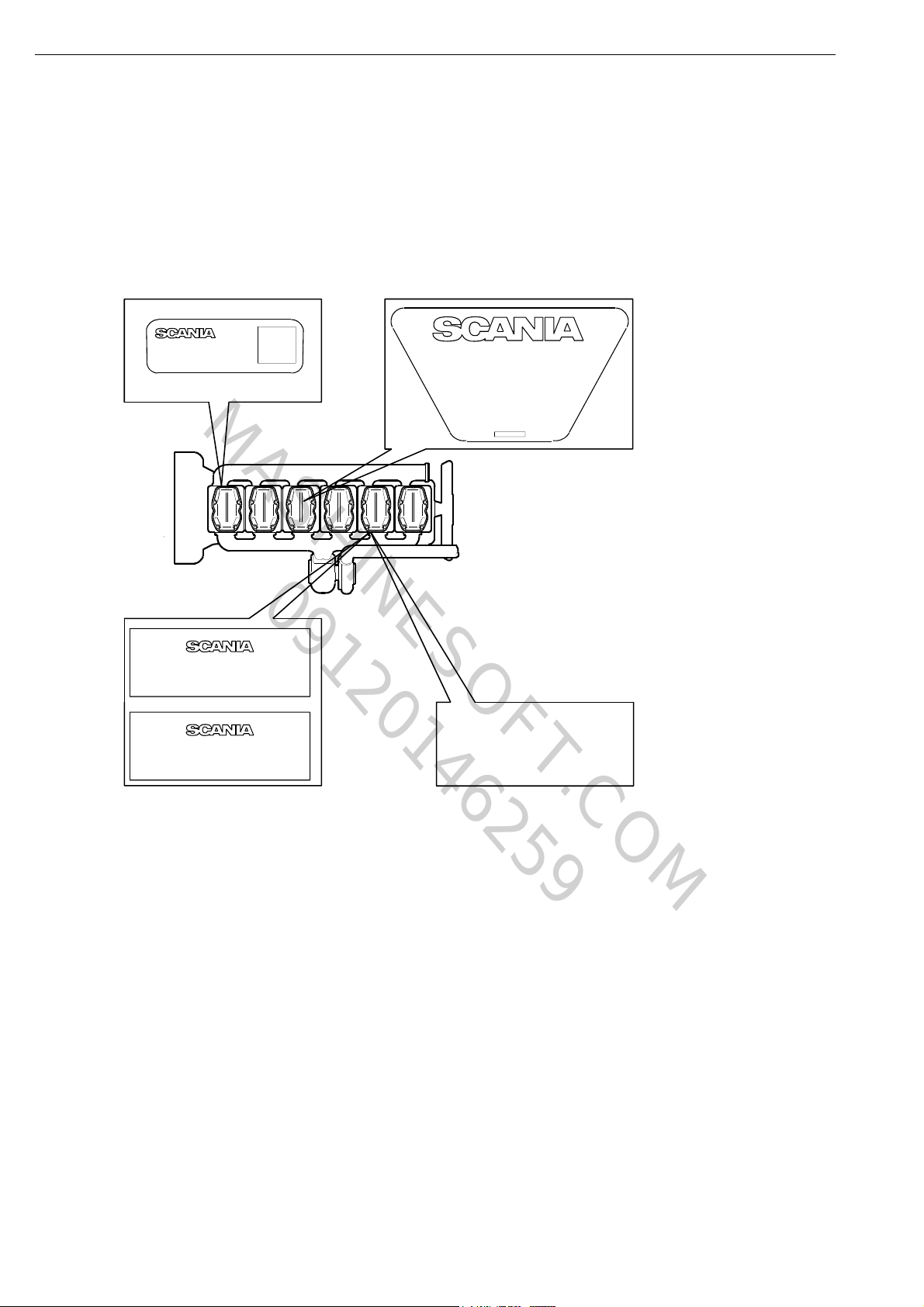
1 Smoke values.
2 Instruction plate.
3 A Engine type, Engine serial number (on engines built before November 2000).
3 B Engine type (on engines built from November 2000 onwards).
4 Engine serial number, stamp.
DC11 DC12
Cylinder diameter 127.0 mm 127.0 mm
Piston stroke 140.0 mm 154.0 mm
Cubic capacity 10.64 dm
3
No. of main bearings 7 7
Firing sequence 1-5-3-6-2-4 1-5-3-6-2-4
©
Scania CV AB 2011, Sweden
11.7 dm
3
01:03-02

Engine assembly
www.motodiesel.ir
MASHINESOFT.COM
09120146259
DC11 DC12
Compression ratio 18:1 18.5:1
Direction of rotation (engine viewed from the rear) Anticlockwise Anticlockwise
Engine speed, low idling 500 rpm 500 rpm
Engine speed, high idling 2,400 rpm 2,400 rpm
Oil capacity 28-35 litres 28-35 litres
Oil grade refer to booklet
00:03-09
Total weight without oil and water 1,010-1,030 kg 1,020-1,040 kg
Lubrication
Engine oil must be applied to all moving parts
before fitting unless otherwise stated.
refer to booklet
00:03-09
01:03-02
©
Scania CV AB 2011, Sweden
5

Engine assembly
www.motodiesel.ir
MASHINESOFT.COM
09120146259
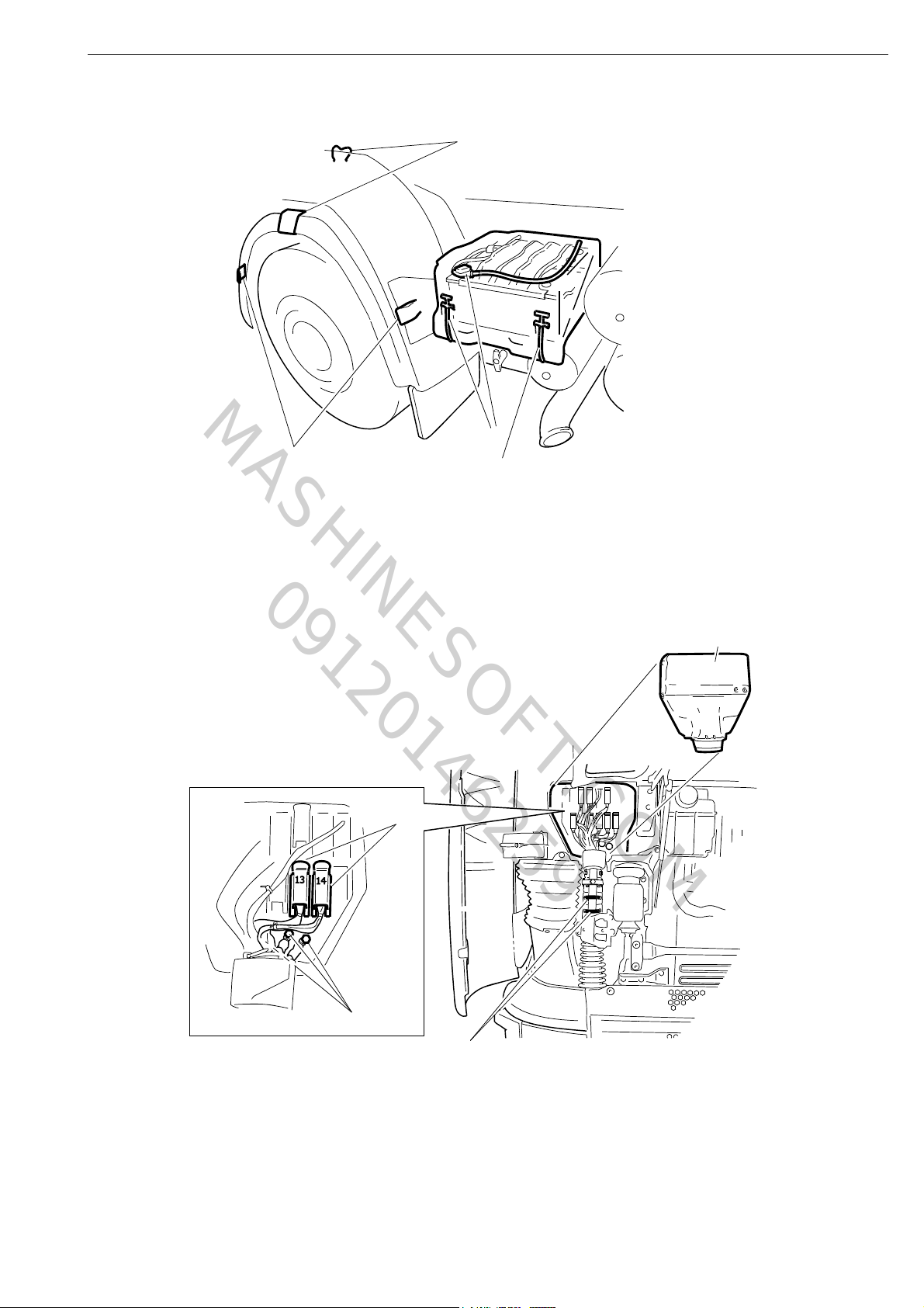
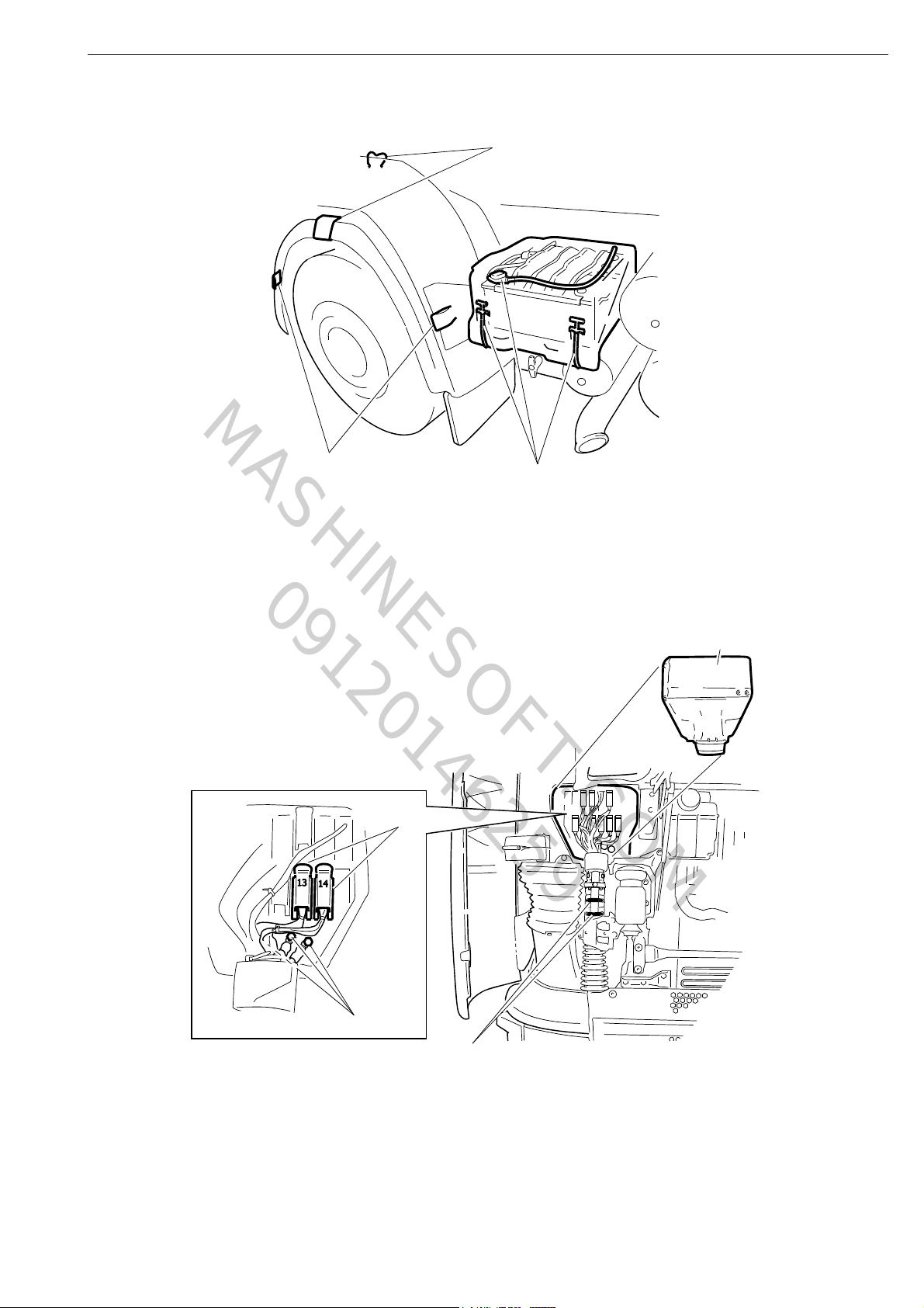
Removing the engine
1 Drain Oil and coolant.
2 Remove The battery cover and detach the
3 Remove The protective casing.
4 Remove Connectors 13 (C2) and 14 (C188). Connector 14 (C188) is only fitted
5 Disconnect The positive and negative cables.
6 Remove The clamps to release electrical cables
7 Tilt the cab according to instructions, refer to Group 18.
Comments
negative cable.
on vehicles without a coordinator.
13 and 14.
8 Remove The mudguards.
6
©
Scania CV AB 2011, Sweden
01:03-02
120232
4
5
3
6
Engine assembly
www.motodiesel.ir
MASHINESOFT.COM
09120146259
8
8
2
120231
01:03-02
©
Scania CV AB 2011, Sweden
7

Engine assembly
www.motodiesel.ir
MASHINESOFT.COM
09120146259
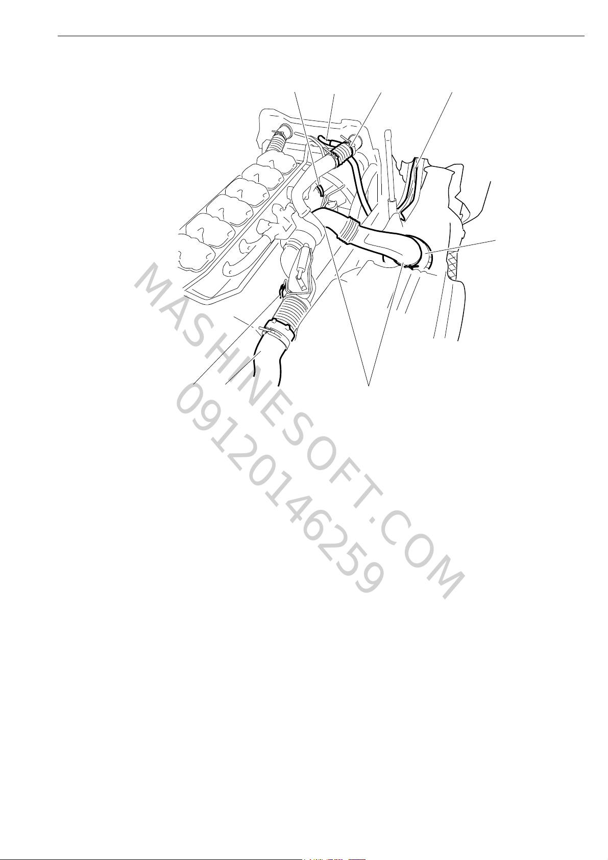
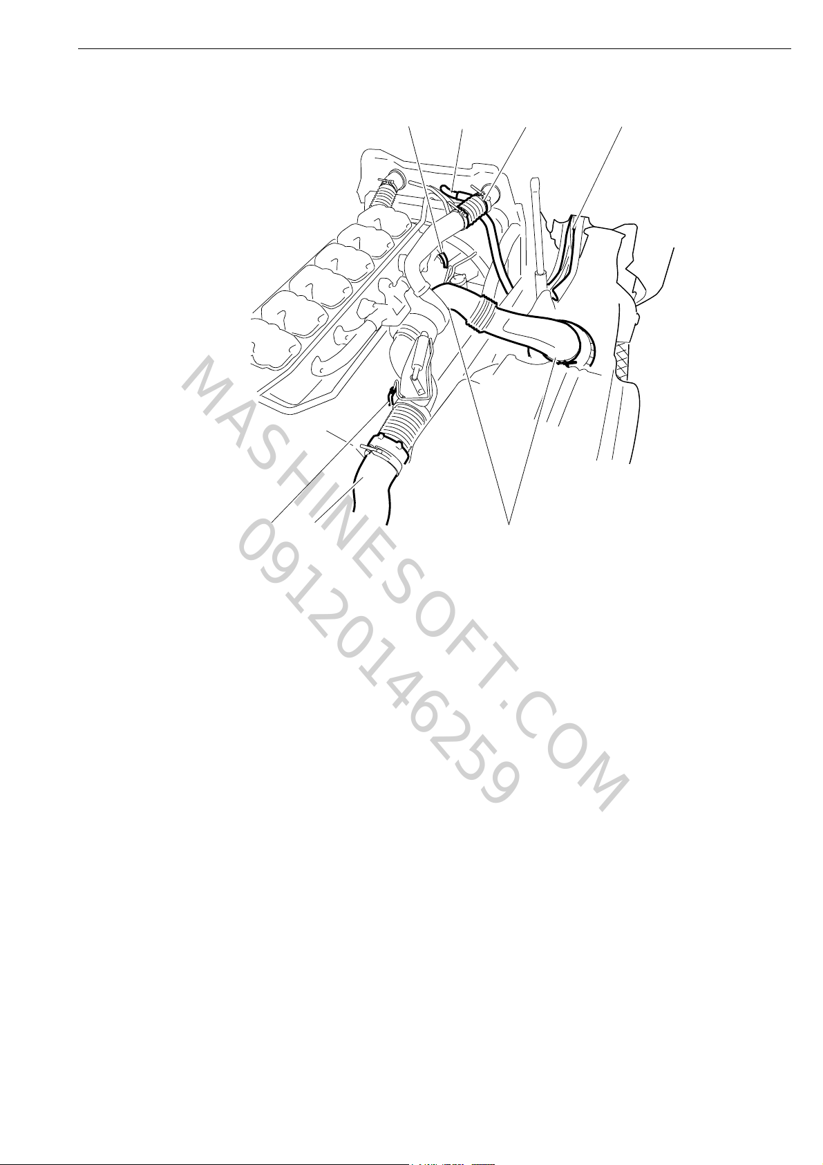
Right-hand side:
9 Pull through the detached cable harnesses and place them on the engine.
10 Remove The turbocharger induction pipe. The compressor air pipe and the
11 Cover the air filter.
12 Detach The radiator water hoses. The number of hoses varies
13 Detach The flexible hose for the charge air pipe.
14 Lift off The poly-V-belt. Only on vehicles with air
Comments
crankcase ventilation hose must be
detached from the induction pipe.
depending on the design. Only one
hose is illustrated.
conditioning.
15 Detach The air hose for the exhaust brake
cylinder.
16 Remove The exhaust pipe.
8
©
Scania CV AB 2011, Sweden
01:03-02
120234
12
9
13
10
16
15
11
14
Engine assembly
www.motodiesel.ir
MASHINESOFT.COM
09120146259
01:03-02
©
Scania CV AB 2011, Sweden
9
100329
99 318
Engine assembly
www.motodiesel.ir
MASHINESOFT.COM
09120146259
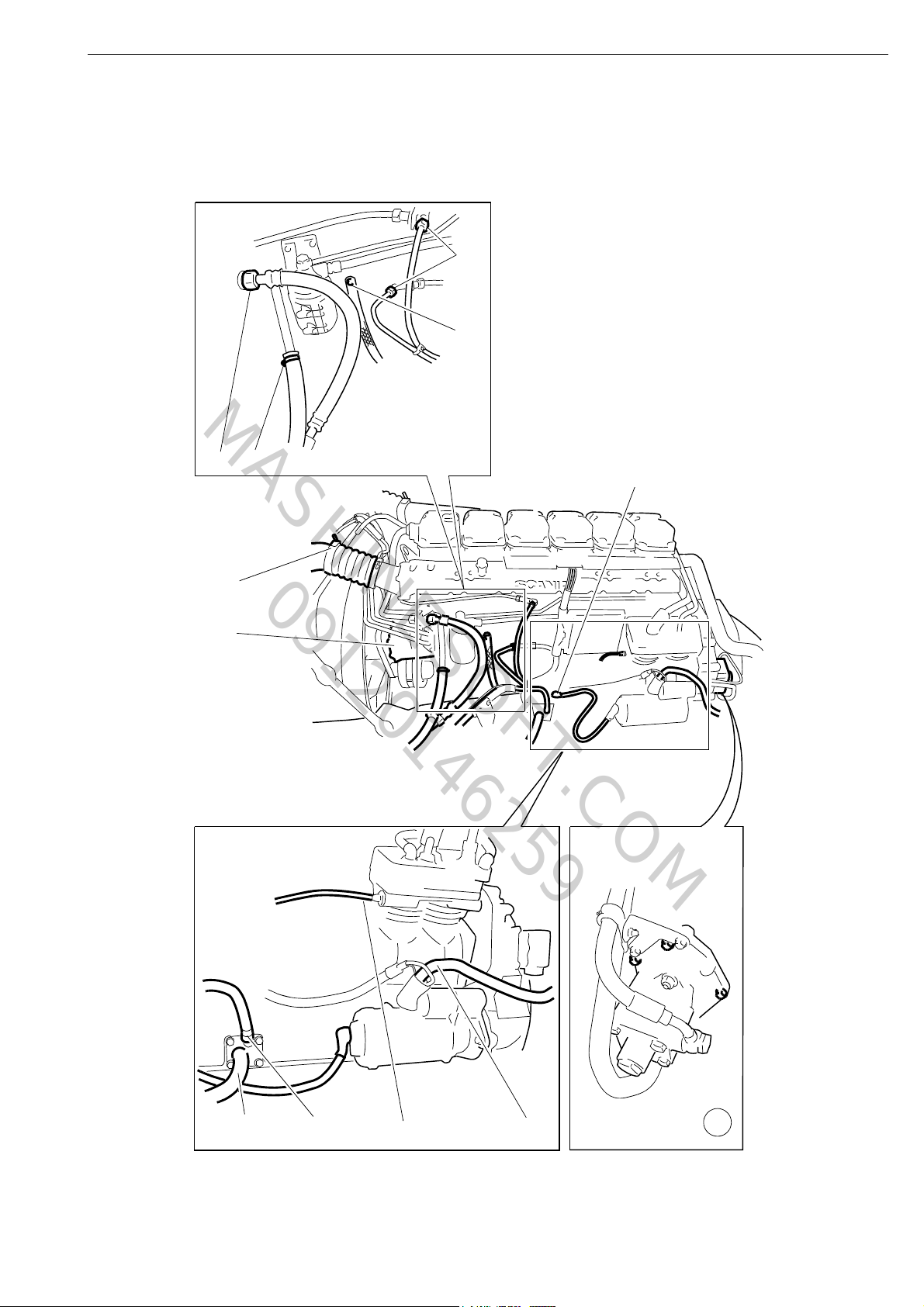
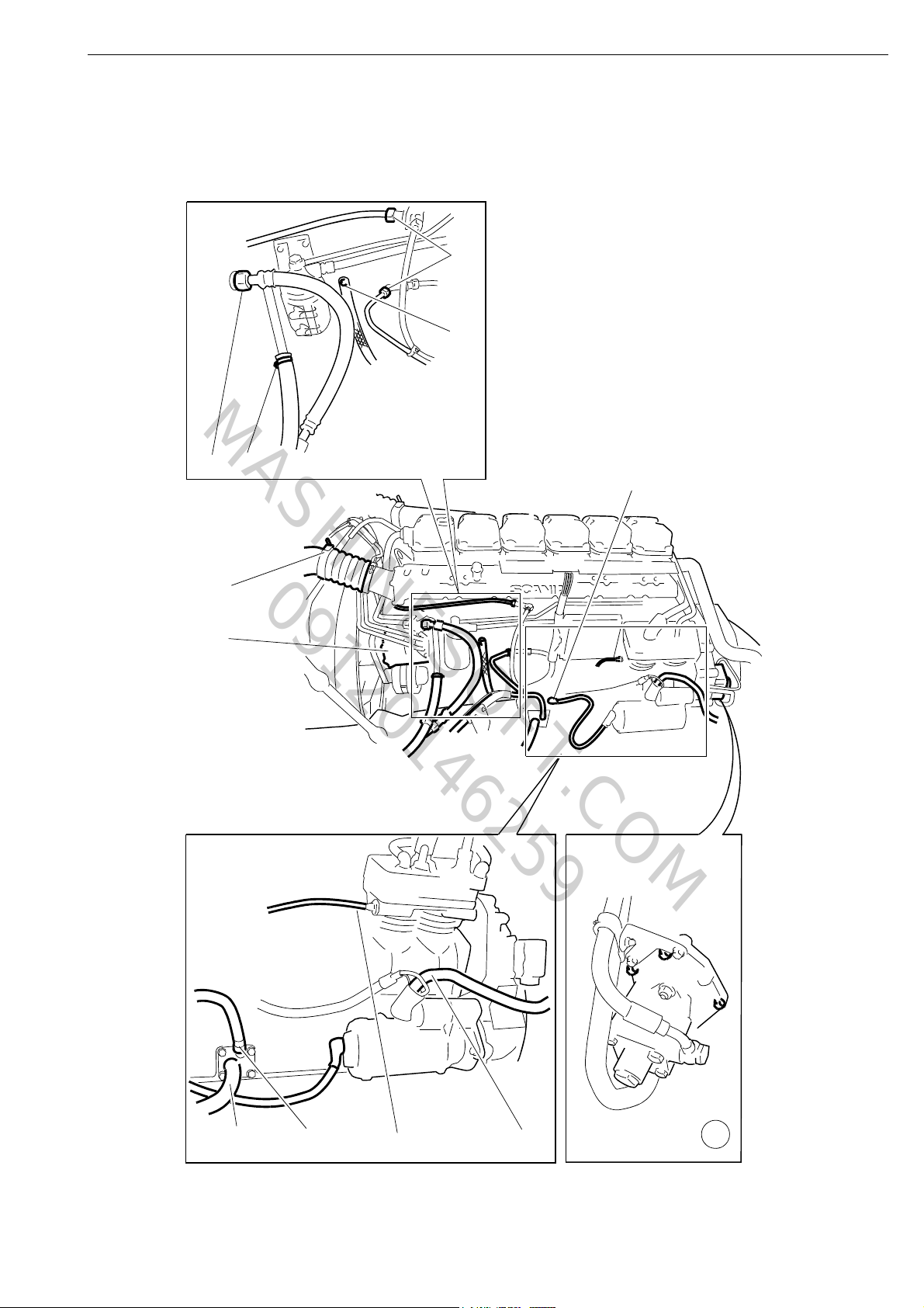
Left-hand side:
17 Detach The flexible hose for the charge air pipe.
18 Detach The AC compressor and move it aside. 4 bolts.
19 Detach The compressor feed pipe.
20 Detach The water heater hose. Only on vehicles equipped with a
21 Detach The ground connection.
22 Detach The fuel pipes.
23 Detach The oil filler hose.
24 Detach The oil dipstick.
25 Detach The starter motor ground connection.
Comments
water heater.
26 Detach The pressure regulator pipe. Detach at the compressor.
27 Detach The positive starter motor cable.
28 Detach The hydraulic pump and move it aside. 5 bolts in the flange.
29 Remove The gearbox. Refer to Group 5.
Note: When removing the gearbox, engine
support 99 318 must be used to support the
engine.
10
©
Scania CV AB 2011, Sweden
01:03-02
120235
17
18
21
22
25
18
19
23
24
26
27
28
www.motodiesel.ir
MASHINESOFT.COM
09120146259
Engine assembly
01:03-02
©
Scania CV AB 2011, Sweden
11
01_1397
98 094
01 1398
587 308
Engine assembly
www.motodiesel.ir
MASHINESOFT.COM
09120146259
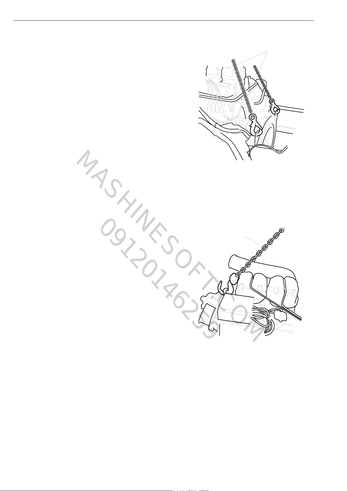
IMPORTANT! The lifting eyes on the engine are
not designed to lift the whole vehicle and
therefore must not be used for this purpose. All
three lifting eyes must be used when lifting the
engine.
On vehicles built from May 2000 onwards, the
rear lifting eyes have been removed. They may be
ordered as a spare part, part number 1 360 442.
30 Fasten lifting chain 98 094 to the rear
lifting eyes.
31 Fasten ratchet lever hoist 587 308 to the
front lifting eye.
12
©
Scania CV AB 2011, Sweden
01:03-02
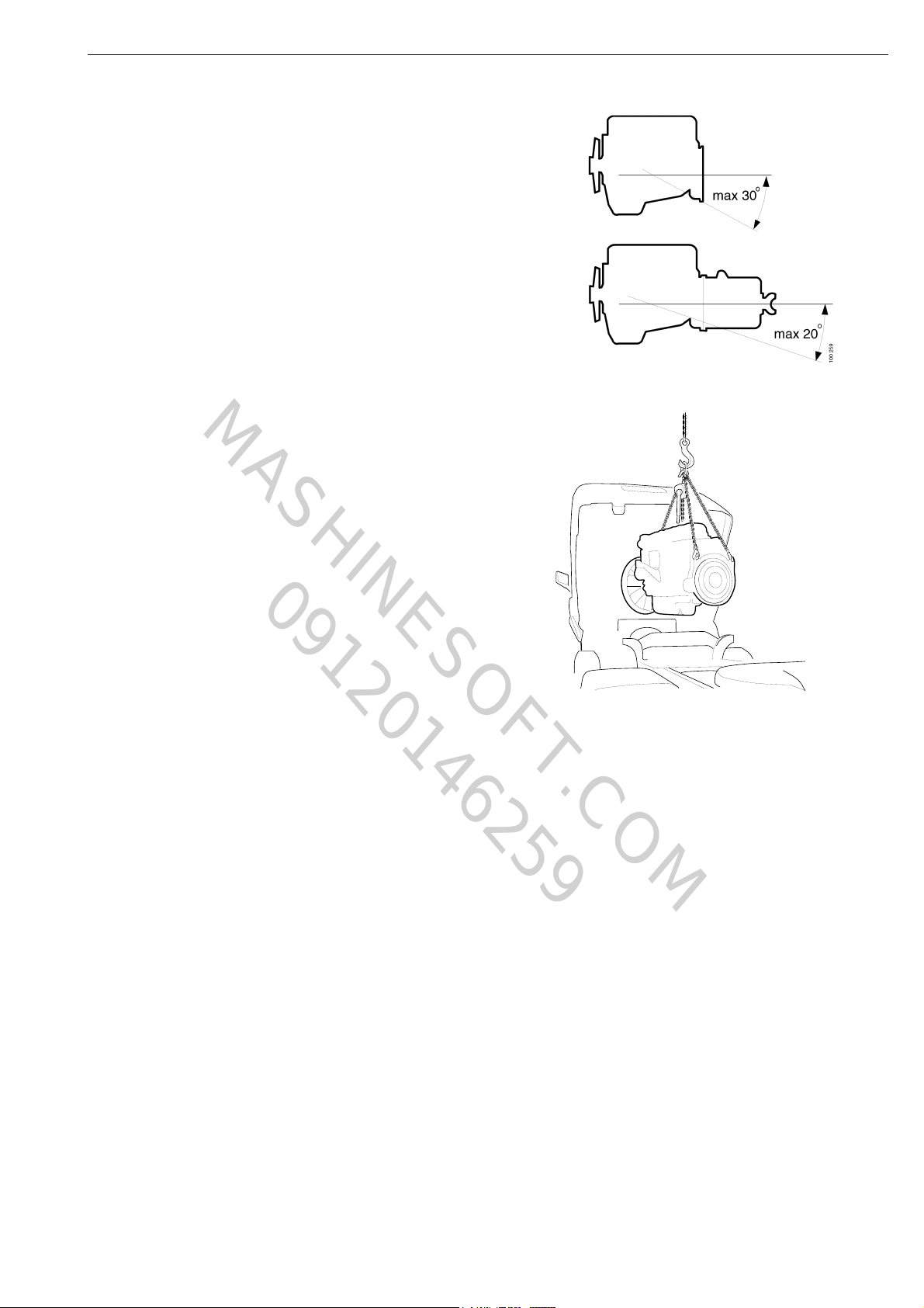
IMPORTANT! The lifting eyes are designed to
01_1399
www.motodiesel.ir
MASHINESOFT.COM
09120146259
cope with a maximum inclination angle of 30°,
when lifting an engine with the gearbox removed.
For engines without the gearbox removed, the
maximum angle is 20°.
32 Remove the bolts in the engine brackets
and lift out the engine.
Engine assembly
01:03-02
©
Scania CV AB 2011, Sweden
13

Engine assembly
www.motodiesel.ir
MASHINESOFT.COM
09120146259
Fitting the engine
Tightening torques
Engine bracket bolts M14: 47 Nm
V-clamp for the charge air cooler 8 Nm
1 Lift the engine so that the engine brackets are approx. 10 mm over the engine cushions.
2 Position the bolts and lower the engine so that it rests on the engine cushions and engine
supports 99
3 Fit the gearbox. Refer to Group 5.
M16: 130 Nm+90°
318. Tightening torques: M14 bolts, 47 Nm and M16 bolts, 130 Nm+90°.
Left-hand side:
Comments
4 Fit The hydraulic pump. Fit a new gasket.
5 Fit The positive starter motor cable.
6 Fit The pressure regulator pipe. At the compressor.
7 Fit The starter motor ground connection.
8 Fit The oil dipstick.
9 Fit The oil filler hose.
10 Fit The fuel pipes. RV= upper, RA= lower.
11 Fit The ground connection. At the compressor.
12 Fit The water heater hose.
13 Fit The compressor feed pipe.
14 Fit The AC compressor.
15 Fit The flexible hose for the charge air pipe. Tightening torque, 8 Nm.
14
©
Scania CV AB 2011, Sweden
01:03-02
120545
15
14
11
10
7
12
13
9
8
6
5
4
www.motodiesel.ir
MASHINESOFT.COM
09120146259
Engine assembly
01:03-02
©
Scania CV AB 2011, Sweden
15

Engine assembly
www.motodiesel.ir
MASHINESOFT.COM
09120146259
Right-hand side:
16 Fit The exhaust pipe.
17 Fit The air hose for the exhaust brake
18 Fit The radiator water hoses. Only one hose is illustrated.
Comments
cylinder.
19 Fit The flexible hose for the charge air
cooler.
20 Fit The turbocharger induction pipe. Tightening torque, 10 Nm, must
21 Fit The compressor air pipe and the
crankcase ventilation hose on the
induction pipe.
22 Fit The poly-V-belt.
23 Route Cables 13 and 14 to the front of the cab.
Tightening torque, 8 Nm.
be applied at max. 100 rpm.
16
©
Scania CV AB 2011, Sweden
01:03-02
120544
18
23
19
20
16
17
22
Engine assembly
www.motodiesel.ir
MASHINESOFT.COM
09120146259
01:03-02
©
Scania CV AB 2011, Sweden
17

Engine assembly
www.motodiesel.ir
MASHINESOFT.COM
09120146259
24 Fit The mudguards.
25 Tilt the cab back to the driving position.
26 Fit The positive and negative cables.
27 Fit Connectors 13(C2) and 14(C188) Connector 14 (C188) is only fitted
28 Fit All cables with clamps.
29 Fit The plastic cover over the central
30 Fit The negative cable on the battery and
Comments
on vehicles without a coordinator.
electric unit.
the battery cover.
18
©
Scania CV AB 2011, Sweden
01:03-02
120542
30
24
24
120543
27
26
29
28
Engine assembly
www.motodiesel.ir
MASHINESOFT.COM
09120146259
01:03-02
©
Scania CV AB 2011, Sweden
19

Engine assembly
www.motodiesel.ir
MASHINESOFT.COM
09120146259
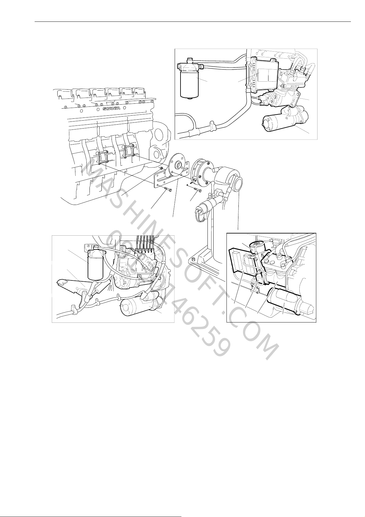
Mounting the engine in an engine stand
Engines with injection pump
Remove: Pos.
Fuel filter A
Injection pump F
Bracket E
Starter motor D
Required brackets
Engines with PDE unit injectors
Remove: Pos.
Fuel filter A
Control unit B
Compressor C
Starter motor D
Required brackets
Engines with HPI unit injectors
Remove: Pos.
Fuel filter A
Control unit B
Compressor C
Starter motor D
Feed pump G
Securely bolt the engine to the engine stand as
illustrated. Use tool 99 331.
20
©
Scania CV AB 2011, Sweden
01:03-02
D
C
99 331
3
2
1
A
B
C
D
E
F
A
D
A
B
G
119 929
Engine assembly
www.motodiesel.ir
MASHINESOFT.COM
09120146259
1 Bolt M10x30 (8 off), Tightening torque 47 Nm.
2 Nut M16 (4 off), Tightening torque 180 Nm.
3 Bolt M16x50 (4 off).
01:03-02
©
Scania CV AB 2011, Sweden
21

100331
Engine assembly
www.motodiesel.ir
MASHINESOFT.COM
09120146259
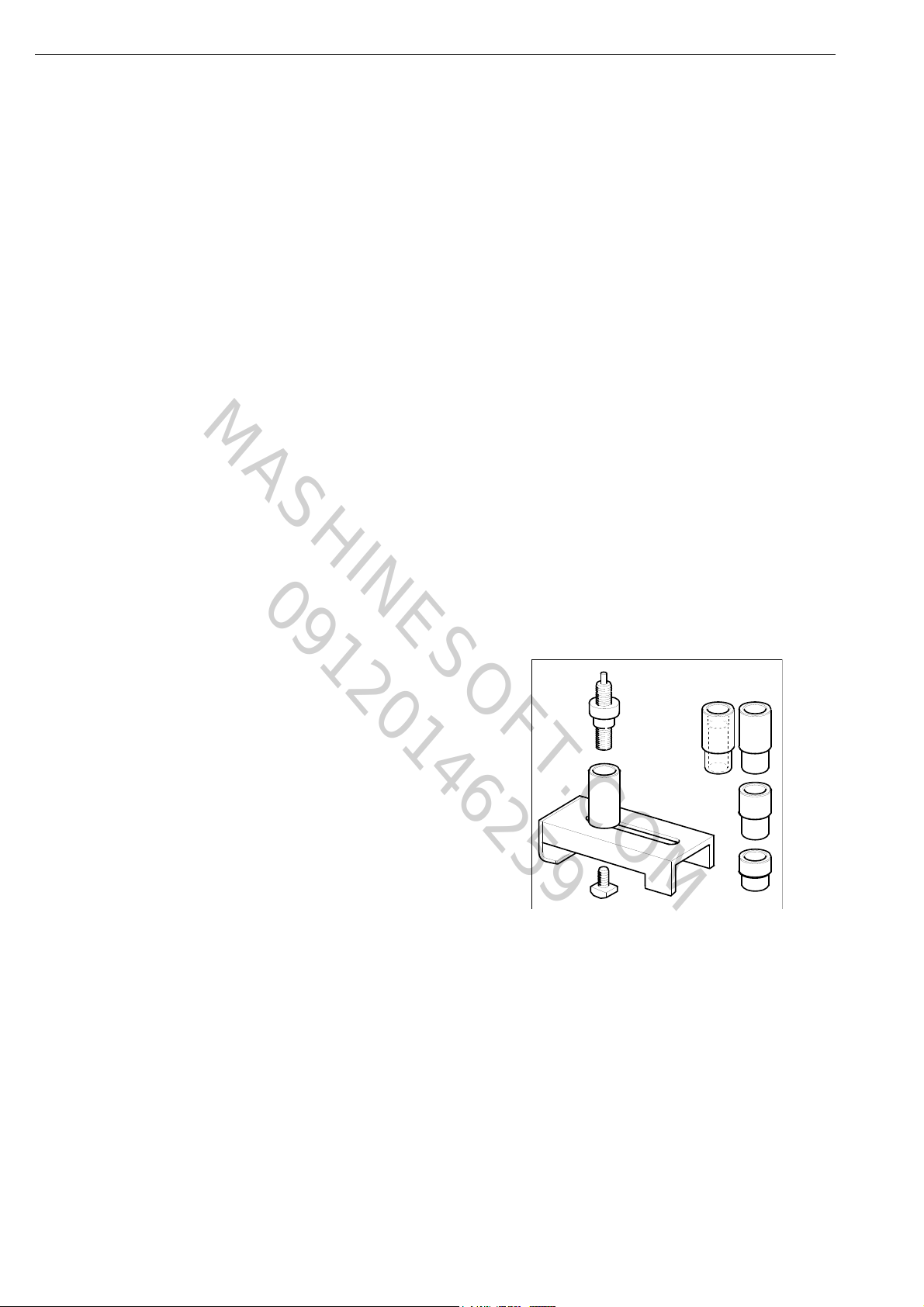
Measuring the compression
pressure
The following description only applies to
engines with an injection pump.
Special tools
Number Denomination Illustration Tool board
98 249 Compression tester MV
99 310 Socket D5
99 074 Impact setting tool D1
99 079 Puller for injector D1
99 308 Sleeve for injector D5
Measuring the compression pressure is used as a
step in troubleshooting. If an engine is running
unevenly, this measurement may indicate
whether one or more cylinders is worn or
damaged. There may be damage to the cylinder
head valves, cylinder liners or piston rings. The
measurement indicates which cylinder(s) should
be subject to further testing.
The results are only intended for comparison
between the cylinders. Lower compression in
one or more of the cylinders is a sign of
abnormal wear or damage.
22
©
Scania CV AB 2011, Sweden
01:03-02

The compression tester can be used on many
www.motodiesel.ir
MASHINESOFT.COM
09120146259
engine types by using various accessories.
It is essential that the battery is fully charged
when carrying out the compression test.
Otherwise, the compression pressure obtained
will be insufficient.
Engine assembly
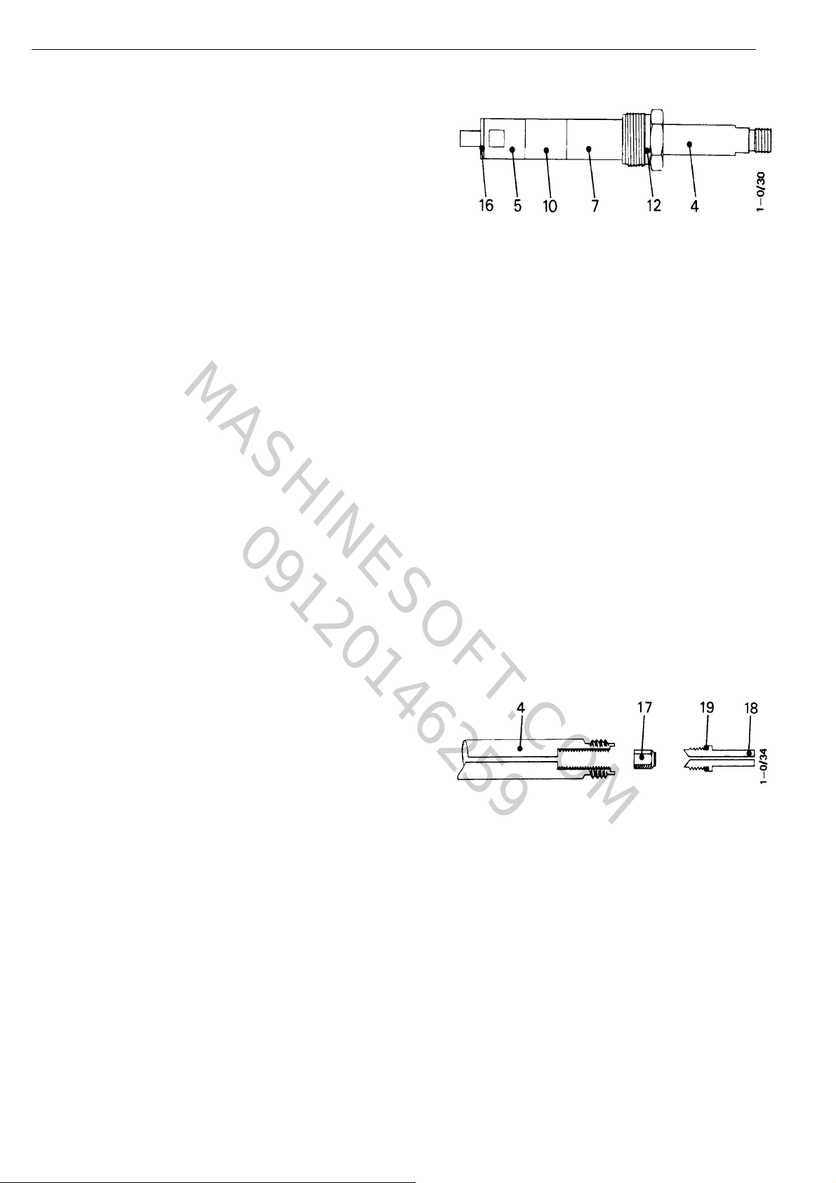
Compression tester 98 249
1 Manometer
2 Reset valve
3 Flexible metal hose
4 Gauge rod
1 Shut off the fuel supply by removing fuse
No. 20 for fuel shut off in the central
electrical unit.
2 Clean around the injectors. Remove the
pressure pipes for the injectors using tool
99 310.
5 End sleeve, diameter 21 mm
6 Spacing sleeve with support lug
7 Spacing sleeve with shoulder
8 Spacing sleeve, length 6 mm
9 Spacing sleeve, length 19 mm
10 Spacing sleeve, length 25 mm
11 Spacing sleeve, length 38 mm
12 Cap nut
13 Threaded socket nut
14 Large yoke
15 Small yoke
IMPORTANT! Place protective caps on the
delivery valve holders on the injection pump
and on the injectors to protect them from dirt.
3 Remove the rocker cover.
4 Remove the injectors and copper washers.
5 Turn the engine with the starter motor a
couple of times to remove any loose soot in
the cylinders.
01:03-02
©
Scania CV AB 2011, Sweden
23
Engine assembly
www.motodiesel.ir
MASHINESOFT.COM
09120146259
6 Connect the compression tester to the
injector hole for one cylinder. Use copper
washer 16 between the compression tester
and the bottom of the injector hole.
4 Gauge rod
7 Turn the engine with the starter motor and
read off the manometer. Note the reading.
8 Reset the manometer by pressing reset
button 2.
9 Move the compression tester to the next
cylinder and continue according to
steps 7-9.
10 Compare the readings between the
cylinders. If one or more cylinders has a
lower compression pressure than the others,
the component parts such as valves, cylinder
liners and piston rings should be checked.
5 End sleeve, diameter 21 mm
7 Spacing sleeve with shoulder
10 Spacing sleeve, length 25 mm
12 Cap nut (Use socket 98 542 to tighten)
16 Copper washer
Gauge rod 4 contains a check valve. In the event
of a leak clean the check valve as follows:
1 Unbolt valve seat 18.
2 Remove any soot from valve 17 and valve
seat 18. Do not scratch the sealing surfaces.
Use compressed air to clean gauge rod 4
internally.
3 Reassemble the parts. Ensure that O-ring 19
is not damaged. Screw valve seat 18 into
place properly so that it forms a seal with
gauge rod 4.
4 Gauge rod
17 Check valve
18 Valve seat
19 O-ring
24
©
Scania CV AB 2011, Sweden
01:03-02
Cylinder head
01 1401
22
20
24
27
23
26
25
22
19
17
5
16
11
21
10
8
4
14
13
15
5
18
2
1
2
6
7
12
3
9
33
37
32
36
34
29
35
31
28
30
www.motodiesel.ir
MASHINESOFT.COM
09120146259
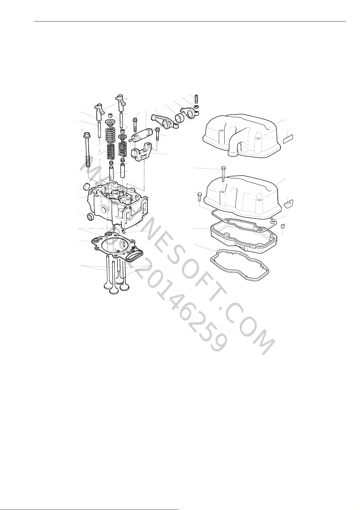
Exploded view
Cylinder head
1 Cylinder head
2 Core plug
3 Rivet plug
4 Valve guide
5 Pin
6 Pin
7 Cylinder head gasket
8 Valve stem seal
9 Intake valve
10 Valve spring
11 Valve spring collar
12 Exhaust valve
13 Valve spring, outer
14 Valve spring, inner
15 Valve spring collar
16 Split collet
17 Valve bridge
18 Bolt
19 Bearing bracket
20 Shaft
21 Rivet plug
22 Tight-fit screw
23 Rocker arm
24 Rocker arm
25 Adjusting screw
26 Nut
27 Spacing sleeve
28 Rocker cover, lower
29 Thread insert
30 Rocker cover gasket, lower
31 Flange screw
32 Rocker cover, upper
33 Rocker cover, upper, on
cylinder 1
34 Rocker cover gasket, upper
35 Flange screw
36 Instruction plate
37 Emission plate
01:03-02
©
Scania CV AB 2011, Sweden
25

99 079
113009
00 1540
99 308
100331
Cylinder head
www.motodiesel.ir
MASHINESOFT.COM
09120146259
Removing the cylinder head (engines with injection pump)
Special tools
Number Denomination Illustration Tool board
99 074 Impact setting tool D1
99 079 Extractor for injector D1
99 308 Sleeve for injector -
99 310 Socket -
1 Remove the pressure pipes using socket
99 310.
2 Detach the intake manifold and remove the
fuel return pipe.
3 Remove the cooling system bleed pipe.
4 Remove the heat shields on the exhaust
manifold and remove the exhaust manifold.
26
©
Scania CV AB 2011, Sweden
01:03-02
Note: All the valve mechanism components
01_1344
01 1345
99 308
01 1346
99 074
99 079
www.motodiesel.ir
MASHINESOFT.COM
09120146259
must be refitted in their original positions.
Therefore, mark the parts as they are removed.
5 Remove the top part of the rocker cover.
6 Remove the shaft, rocker arms, bearing
brackets and pushrods.
7 Remove the lower part of the rocker cover.
Cylinder head
8 Undo the injector nut using socket 99 308.
9 Pull out the injectors with tools 99 079 and
99
074.
10 Remove the cylinder head. Mark the
cylinder heads if more than one is being
removed at the same time.
01:03-02
©
Scania CV AB 2011, Sweden
27
!
WARNING!
108 036
120513
4
Cylinder head
www.motodiesel.ir
MASHINESOFT.COM
09120146259
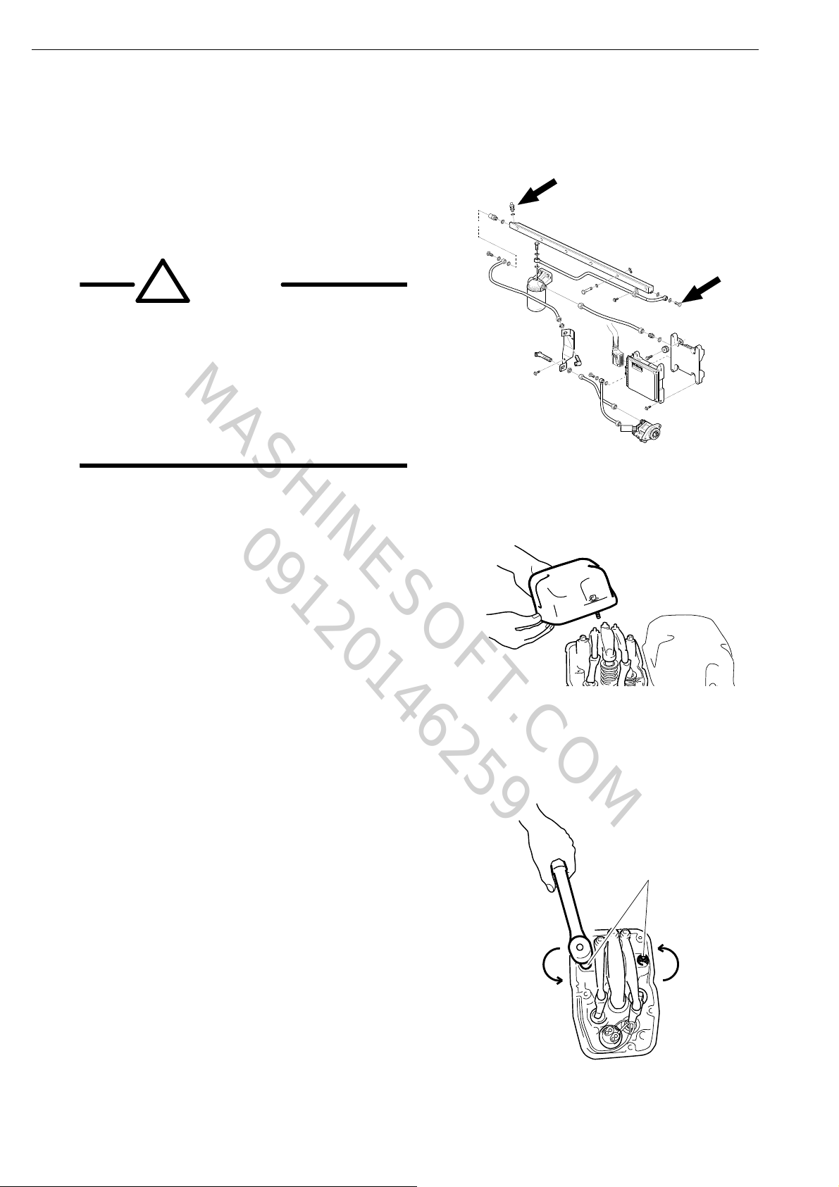
Removing the cylinder head (engines with PDE unit injectors)
1 Open the bleed nipple and drain the fuel
system by undoing the banjo screw on the
back of the fuel manifold.
The fuel system must be empty or fuel
may run down into the cylinders, which
will result in a great risk of liquid
slugging.
If fuel runs into the combustion
chamber, it must be removed
immediately using a pump.
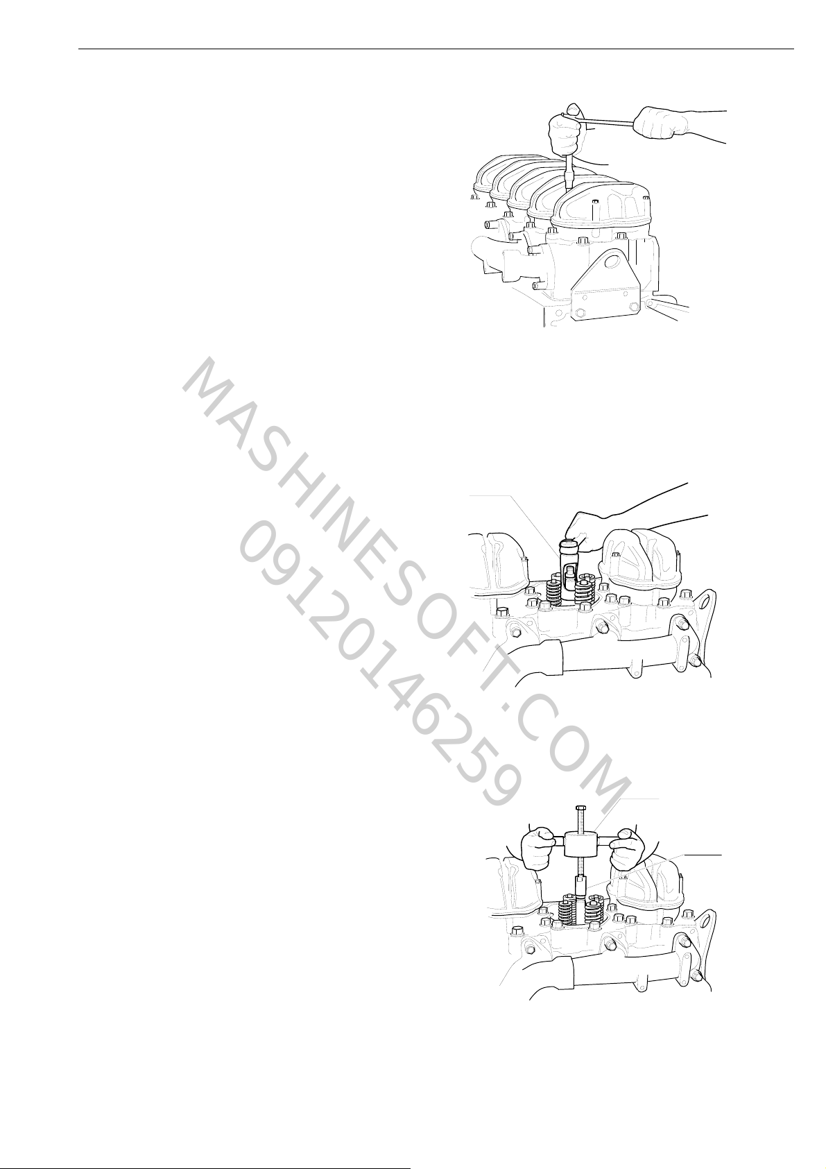
2 Clean the rocker cover and the area around
it.
3 Remove the top part of the rocker cover.
4 Relieve the pressure on the valves by
undoing the bolts on the rocker arm shaft
alternately.
28
©
Scania CV AB 2011, Sweden
01:03-02
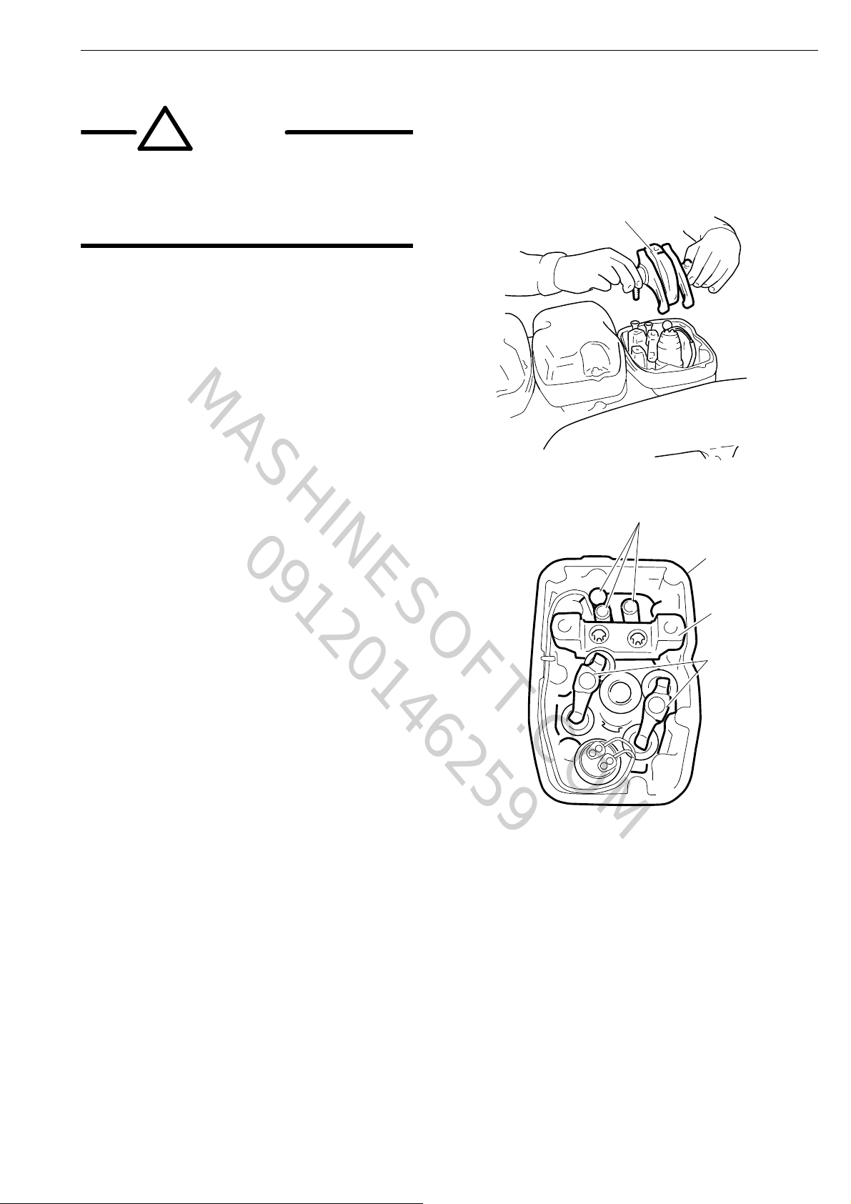
!
WARNING!
Do not lean over the engine when
120519
5
120514
9
6
8
7
www.motodiesel.ir
MASHINESOFT.COM
09120146259
removing the rocker arm shaft. The unit
injector spring is pre-tensioned and can
come loose, causing personal injury.
Note: If the spring comes loose from the unit
injector, the unit injector must be renewed.
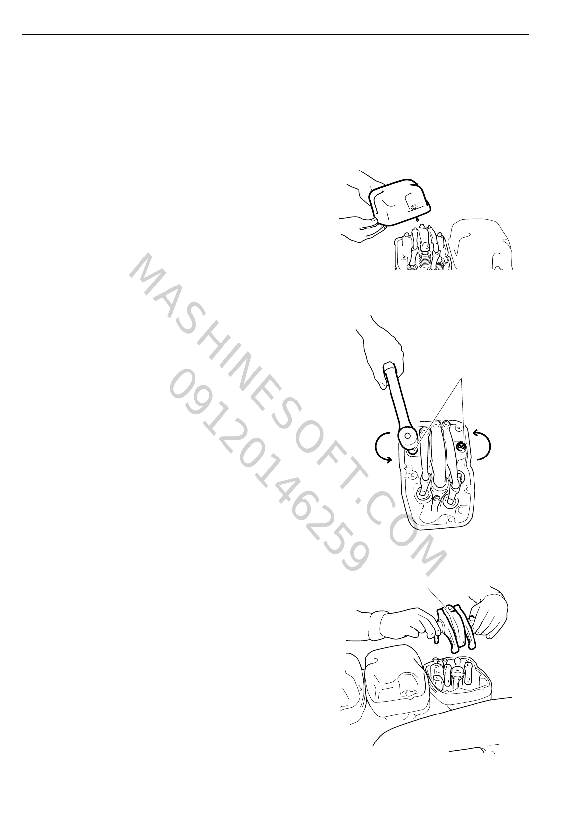
5 Remove the rocker arm shaft.
Cylinder head
6 Remove the bearing bracket.
7 Remove the pushrods.
Note: The pushrod for the unit injector is
secured with a retaining ring. Jiggle and pull
carefully on the pushrod to loosen it.
8 Remove the valve bridges.
9 Remove the lower rocker cover.
10 Remove the unit injector according to the
section Removing the unit injector, steps
6-10 in booklet 03:04-01.
11 Detach the intake manifold, fuel manifold,
12 Remove the cylinder head. Mark the
cooling system bleed pipe and the exhaust
manifold.
cylinder heads if more than one is being
removed at the same time.
01:03-02
©
Scania CV AB 2011, Sweden
29
120515
3
120520
4
Cylinder head
www.motodiesel.ir
MASHINESOFT.COM
09120146259
Removing the cylinder head (engines with HPI unit injectors)
1 Clean the rocker cover and the area around
it.
2 Remove the top part of the rocker cover.
3 Relieve the pressure on the valves by
undoing the bolts on the rocker arm shaft
alternately.
4 Remove the rocker arm shaft.
30
©
Scania CV AB 2011, Sweden
01:03-02
 Loading...