

Samsung SNZ-5200 User Manual

NETWORK CAMERA
User Manual
SNZ-5200

Network Camera
User Manual
Copyright
©2011 Samsung Techwin Co., Ltd. All rights reserved.
Trademark
The name of this product is the registered trademark of Samsung Techwin Co., Ltd.
Other trademarks mentioned in this manual are the registered trademark of their respective company.
Restriction
Samsung Techwin Co., Ltd shall reserve the copyright of this document. Under no circumstances, this
document shall be reproduced, distributed or changed, partially or wholly, without formal authorization of
Samsung Techwin.
Disclaimer
Samsung Techwin makes the best to verify the integrity and correctness of the contents in this document, but
no formal guarantee shall be provided. Use of this document and the subsequent results shall be entirely on
the user’s own responsibility. Samsung Techwin reserves the right to change the contents of this document
without prior notice.
Warranty
If the product does not operate properly in normal conditions, please let us know. Samsung Techwin will resolve
the problem for free of charge. The warranty period is 3 years. However, the followings are excluded:
•
If the system behaves abnormally because you run a program irrelevant to the system operation.
•
Deteriorated performance or natural worn-out in process of time
is the registered logo of Samsung Techwin Co., Ltd.

overview
IMPORTANT SAFETY INSTRUCTIONS
Read these instructions.
1.
Keep these instructions.
2.
Heed all warnings.
3.
Follow all instructions.
4.
Do not use this apparatus near water.
5.
Clean only with dry cloth.
6.
Do not block any ventilation openings, Install in accordance with the manufacturer’s
7.
instructions.
Do not install near any heat sources such as radiators, heat registers, stoves, or other
8.
apparatus (including amplifiers) that produce heat.
Do not defeat the safety purpose of the polarized or grounding-type plug. A polarized
9.
plug has two blades with one wider than the other. A grounding type plug has two
blades and a third grounding prong. The wide blade or the third prong are provided for
your safety. If the provided plug does not fit into your outlet, consult an electrician for
replacement of the obsolete outlet.
Protect the power cord from being walked on or pinched particularly at plugs,
10.
convenience receptacles, and the point where they exit from the apparatus.
Only use attachments/ accessories specified by the manufacturer.
11.
Use only with the cart, stand, tripod, bracket, or table specified by
12.
the manufacturer, or sold with the apparatus. When a cart is used,
use caution when moving the cart/apparatus combination to avoid
injury from tip-over.
Unplug this apparatus during lighting storms or when unused for
13.
long periods of time.
Refer all servicing to qualified service personnel. Servicing is required when the
14
.
apparatus has been damaged in any way, such as power-supply cord or plug is
damaged, liquid has been spilled or objects have fallen into the apparatus, the apparatus
has been exposed to rain or moisture, does not operate normally, or has been dropped.
● OVERVIEW
English _3
overview
WARNING
TO REDUCE THE RISK OF FIRE OR ELECTRIC SHOCK, DO NOT EXPOSE
THIS PRODUCT TO RAIN OR MOISTURE. DO NOT INSERT ANY METALLIC
OBJECT THROUGH THE VENTILATION GRILLS OR OTHER OPENNINGS
ON THE EQUIPMENT.
Apparatus shall not be exposed to dripping or splashing and that no objects
filled with liquids, such as vases, shall be placed on the apparatus.
CAUTION
CAUTION
RISK OF ELECTRIC SHOCK.
DO NOT OPEN
CAUTION
REFER SERVICING TO QUALIFIED SERVICE PERSONNEL.
: TO REDUCE THE RISK OF ELECTRIC SHOCK.
DO NOT REMOVE COVER (OR BACK).
NO USER SERVICEABLE PARTS INSIDE.
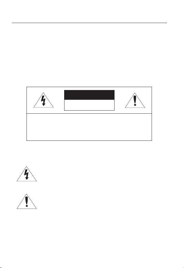
EXPLANATION OF GRAPHICAL SYMBOLS
The lightning flash with arrowhead symbol, within an
equilateral triangle, is intended to alert the user to the
presence of “dangerous voltage” within the product’s
enclosure that may be of sufficient magnitude to constitute a
risk of electric shock to persons.
The exclamation point within an equilateral triangle is intended
to alert the user to the presence of important operating
and maintenance (servicing) instructions in the literature
accompanying the product.
4_ overview

Class construction
An apparatus with CLASS construction shall be connected to a MAINS
socket outlet with a protective earthing connection.
Battery
Batteries(battery pack or batteries installed) shall not be exposed to excessive
heat such as sunshine, fire or the like.
Disconnection Device
Disconnect the main plug from the apparatus, if it’s defected. And please call
a repair man in your location.
When used outside of the U.S., it may be used HAR code with fittings of
an approved agency is employed.
CAUTION
These servicing instructions are for use by qualified service personnel only.
To reduce the risk of electric shock do not perform any servicing other than
that contained in the operating instructions unless you are qualified to do so.
The BNC Out terminal of the product is provided for easier installation, and is
not recommended for monitoring purposes.
If you keep the BNC cable connected, a risk of lightening may cause damage
or malfunction to the product.
Please use the input power with just one camera and other devices must not
be connected.
● OVERVIEW
English _5
overview
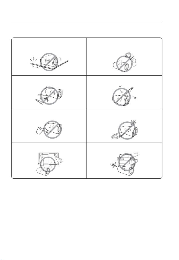
Please read the following recommend safety precautions carefully.
Do not place this apparatus on an uneven surface. Do not install on a surface where it is exposed to direct
Do not place this apparatus near conductive material. Do not attempt to service this apparatus yourself.
Do not place a glass of water on the product. Do not install near any magnetic sources.
Do not block any ventilation openings. Do not place heavy items on the product.
User’s Manual is a guidance book for how to use the products.
The meaning of the symbols are shown below.
y
Reference : In case of providing information for helping of product’s usages
y
Notice : If there’s any possibility to occur any damages for the goods and
human caused by not following the instruction
Ú
Please read this manual for the safety before using of goods and keep it in
the safe place.
sunlight, near heating equipment or heavy cold area.
6_ overview
This equipment has been tested and found to comply with the limits for a
Class A digital device, pursuant to part 15 of the FCC Rules. These limits are
designed to provide reasonable protection against harmful interference when
the equipment is operated in a commercial environment.
This equipment generates, uses, and can radiate radio frequency energy and,
if not installed and used in accordance with the instruction manual, may cause
harmful interference to radio communications. Operation of this equipment in a
residential area is likely to cause harmful interference in which case the user will
be required to correct the interference at his own expense.
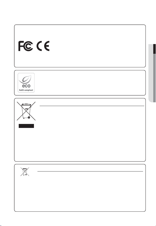
Samsung Techwin cares for the environment at all product manufacturing stages, and is
taking measures to provide customers with more environmentally friendly products.
The Eco mark represents Samsung Techwin’s devotion to creating environmentally friendly
products, and indicates that the product satisfies the EU RoHS Directive.
Correct Disposal of This Product (Waste Electrical & Electronic Equipment)
(Applicable in the European Union and other European countries with separate collection systems)
This marking on the product, accessories or literature indicates that the product and its
electronic accessories (e.g. charger, headset, USB cable) should not be disposed of with other
household waste at the end of their working life. To prevent possible harm to the environment or
human health from uncontrolled waste disposal, please separate these items from other types
of waste and recycle them responsibly to promote the sustainable reuse of material resources.
Household users should contact either the retailer where they purchased this product, or
their local government office, for details of where and how they can take these items for
environmentally safe recycling.
Business users should contact their supplier and check the terms and conditions of the
purchase contract. This product and its electronic accessories should not be mixed with other
commercial wastes for disposal.
Correct disposal of batteries in this product
(Applicable in the European Union and other European countries with separate battery return systems.)
This marking on the battery, manual or packaging indicates that the batteries in this product should
not be disposed of with other household waste at the end of their working life. Where marked, the
chemical symbols Hg, Cd or Pb indicate that the battery contains mercury, cadmium or lead above the
reference levels in EC Directive 2006/66. If batteries are not properly disposed of, these substances
can cause harm to human health or the environment.
To protect natural resources and to promote material reuse, please separate batteries from other types
of waste and recycle them through your local, free battery return system.
● OVERVIEW
English _7

overview
CONTENTS
OVERVIEW
3
INSTALLATION &
CONNECTION
15
NETWORK CONNECTION
AND SETUP
20
3 Important Safety Instructions
10 Product Features
10 Recomended PC Specifications
11 Recomended Micro SD/SDHC
Memory Card Specifications
11 What’s Included
12 At a Glance
15 Inserting/Removing an Micro SD
Memory Card
16 Memory Card Information
(Not Included)
17 Connecting with other Device
20 Connecting the Camera Directly
to Local Area Networking
21 Connecting the Camera Directly
to a DHCP Based DSL/Cable
Modem
22 Connecting the Camera Directly
to a PPPoE Modem
23 Connecting the Camera to a
Broadband Router with the
PPPoE/Cable Modem
24 Buttons used in IP Installer
25 Static IP Setup
28 Dynamic IP Setup
29
Port Range Forward (Port Mapping)
Setup
31 Connecting to the Camera from a
Shared Local PC
31 Connecting to the Camera from a
Remote PC via the Internet
8_ overview

WEB VIEWER
32
32 Connecting to the Camera
33 Login
34 Installing Silverlight Runtime
36 Using the Live Screen
39 Playback
40 Playing the backup recordings
● OVERVIEW
SETUP SCREEN
41
APPENDIX
70
41 Setup
41 Audio & Video Setup
51 Network Setup
57 Event Setup
65 System Setup
70 Specification
74 Product Overview
75 Troubleshooting
77 Open Source Announcement
79 GPL/LGPL Software License
English _9

overview
PRODUCT FEATURES
HD Video Quality
•
Multi-Streaming
•
This network camera can display videos in different resolutions and qualities
simultaneously using different CODECs.
However, MPEG-4 video can not be played on a web page. Use CMS software if you want to play
M
the video on a web page.
Web Browser-based Monitoring
•
Using the Internet web browser to display the image in a local network environment.
Alarm
•
If an event occurs, the event-related video will be transferred to the email specified by the
user or saved to the Micro SD memory, or the event signal will be sent to the Alarm Out port.
Intelligent Video Analysis
•
Analyzes the event video according to the user-specified rules to recognize the event.
ONVIF (Spec 1.01) Compliance
•
This product supports ONVIF Core Spec. 1.01.
For more information, refer to www.onvif.org.
RECOMENDED PC SPECIFICATIONS
CPU : Intel(R) Core(TM)2 2.00 GHz or higher
•
Operating System : Windows XP, VISTA, 7
•
Resolution : 1280X1024 pixels or higher
•
RAM : 1GB or higher
•
Web Browser : Internet Explorer 6.0 or higher
•
Neither a beta test version unlike the version released in the company website nor the developer version will
be supported.
On Firefox v3.5 or higher, displaying warning message dialog may cause an error.
If connecting to IPv6 in Windows XP, it can cause some problem.
It is recommended to connect to IPv6 in Windows 7.
Video Memory : 128MB or higher
•
Mac OS
Firefox, Google Chrome, Safari
10_ overview
RECOMENDED MICRO SD/SDHC MEMORY CARD
SPECIFICATIONS
2GB ~ 32GB
•
To ensure proper recording of video data, it is recommended you use a memory card that
•
supports at least read/write speed 10Mbps and Class 6.
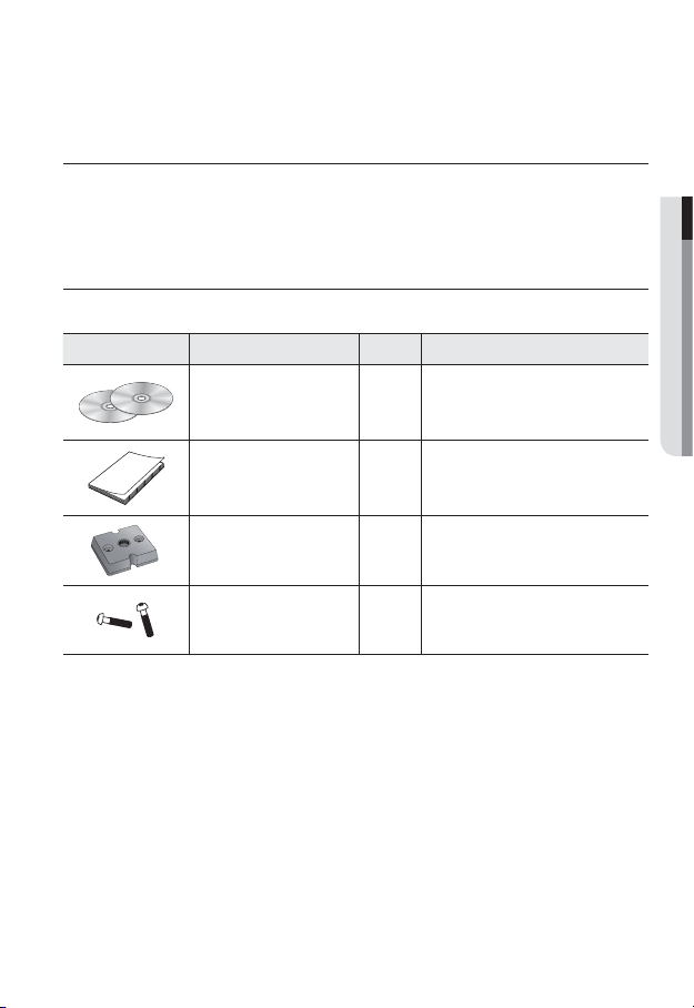
WHAT’S INCLUDED
Please check if your camera and accessories are all included in the product package.
Appearance Item Name Quantity Description
User Manual,
Installer S/W DVD,
CMS S/W DVD
Quick Guide 1
Camera Holder (Mount) 1 Used to install the camera holder
Camera Holder (Mount) Screws 2 Used to install the mount
2
● OVERVIEW
English _11
overview
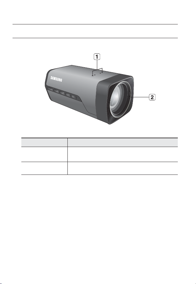
AT A GLANCE
Front Side
Item Description
Camera Holder
(Mount) Holes
Zoom Lens Built-in zoom lens.
b
Wipe out a dirty surface of the lens softly with a lens tissue or cloth to which you have applied
M
ethanol.
Used when you mount the camera onto the bracket by fixing the camera
holder (mount) adaptor with the bracket.
12_ overview
Rear Side
SD CARD
SD CARDSD CARD
VIDEO
1 : ALARM OUT 4 : GND
2 : ALARM IN 5 : RS-485+
3 : ALARM COM
6 : RS-485-
AUDIO OUT
SD SYSTEM POWER
RESET
NETWORK
● OVERVIEW
AUDIO IN
GND
+
1 2 3 4 5 6
Item Description
Micro SD Memory
Card Compartment
Audio terminal
b
Compartment for the Micro SD memory card.
AUDIO OUT Terminal for audio output.
AUDIO IN Terminal for audio input.
ON : A memory card is inserted and operates normally.
Flashing : Failed to record, insufficient space, or inserted
SD
OFF : Camera is off, camera is restarting, or memory card is
System, Power,
c
SD Indicators
SYSTEM
ON : The camera is turned on and connected to the network
Flashing : During DDNS setup, or in case of setup failure, or
OFF : When the system is rebooting, or turned off.
LINK
DC 12V
ACT
abnormally.
not in place.
properly.
in a state of unstable network connection.
English _13

overview
Item Description
System, Power,
c
SD Indicators
Reset Button
GND Used for earth-grounding.
Power Port Used to plug the power cable.
Network Port Used to connect a PoE or LAN cable.
I/O Port
POWER
Resets the camera settings to the default. Press and hold it for about 5
seconds to turn off the system indicator and restart the system.
J
ALARM OUT Used to connect the alarm output signal.
ALARM IN Used to connect the alarm input signal.
ALARM COM Common port where the alarm output signal is connected.
GND Used for earth-grounding.
RS-485+ RS-485 Data line
RS-485- RS-485 Data line
ON : While the power is on
OFF : If the power is off
If you reset the camera, the network settings will be adjusted so that
DHCP can be enabled. If there is no DHCP server in the network, you
must run the IP Installer program to change the basic network settings
such as IP address, Subnet mask, Gateway, etc., before you can
connect to the network.
Video Out Port Analog video output port. (for installation)
J
14_ overview
RS-485 port only supports direct connection with pan/tilt driver and external connections of the
RS-485 controller is not supported.
VIDEO
VIDEO
installation & connection
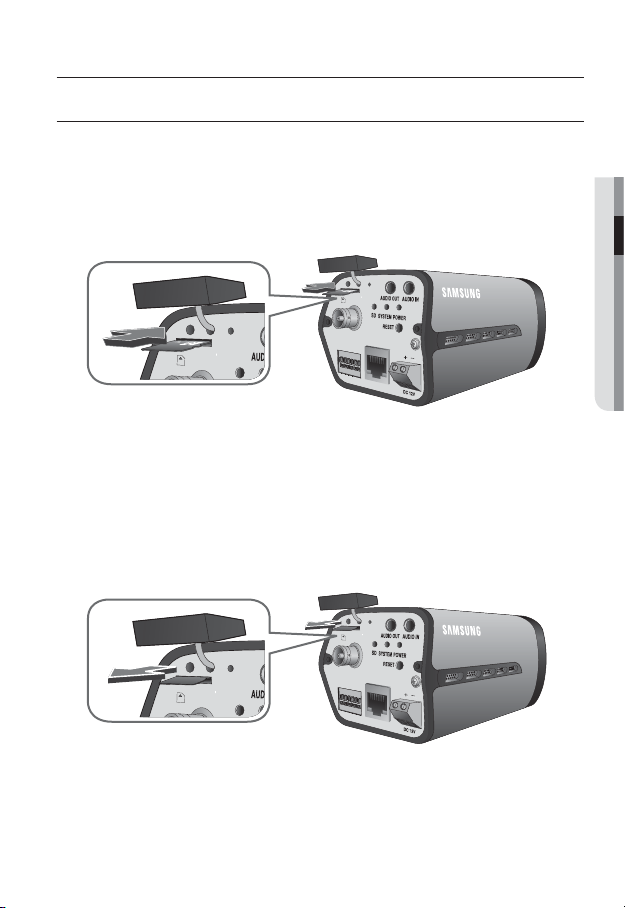
INSERTING/REMOVING AN MICRO SD MEMORY CARD
Disconnect the power cable from the camera before inserting the Micro SD memory card.
J
Inserting an Micro SD Memory Card
As shown, loosen the screw before removing the Micro SD memory card. Insert the micro
Micro SD card in the arrow direction.
VIDEO
● INSTALLATION & CONNECTION
ALARM OUT 4
ALARM IN 5 : RS-485+
ALARM COM
1
2 3
GND
NETWORK
:
GND
6: RS-485-
4
5
6
ACT
LINK
1:
2:
3:
Do not insert the Micro SD memory card while it’s upside down by force. Otherwise, it may
J
damage the Micro SD memory card.
Removing an Micro SD Memory Card
Gently press down on the exposed end of the memory card as shown in the diagram to
eject the memory card from the slot.
VIDEO
: ALARM OUT 4
ALARM IN 5 :
ALARM COM
1
GND
NETWORK
:
GND
RS-485+
6
: RS-485-
2 3
4
5
6
ACT
LINK
English _15
1
2:
3:

installation & connection
Pressing too hard on the Micro SD memory card can cause the card to shoot out uncontrollably
J
from the slot when released.
To remove the Micro SD memory card, set <Record> to <Off> from <SD record> and press
[Apply (
If you have saved data in the Micro SD memory card, removing the Micro SD memory card prior
to setting record to OFF will cause damage to the data stored in the card.
If the Micro SD memory is inserted, the SD LED indicator on the rear of the camera will turn on.
If there occurs a problem in the Micro SD memory, the SD LED indicator will blink.
MEMORY CARD INFORMATION (NOT INCLUDED)
What is a memory card?
The memory card is an external data storage device that has been developed to offer an
entirely new way to record and share video, audio, and text data using digital devices.
Selecting a memory card that’s suitable for you
Your camera supports Micro SD/SDHC memory cards.
You may, however, experience compatibility issues depending on the model and make of
the memory card.
For your camera, we recommend you use a memory card from the following
manufacturers:
Micro SD/SDHC Memory Card : Sandisk, Transcend, Kingston
Playback performance can be affected depending on the speed of memory card, so use
the high-speed memory card.
❖
Memory Card Components
Contacts
)]. (page 58)
Micro SD/SDHC
16_ installation & connection
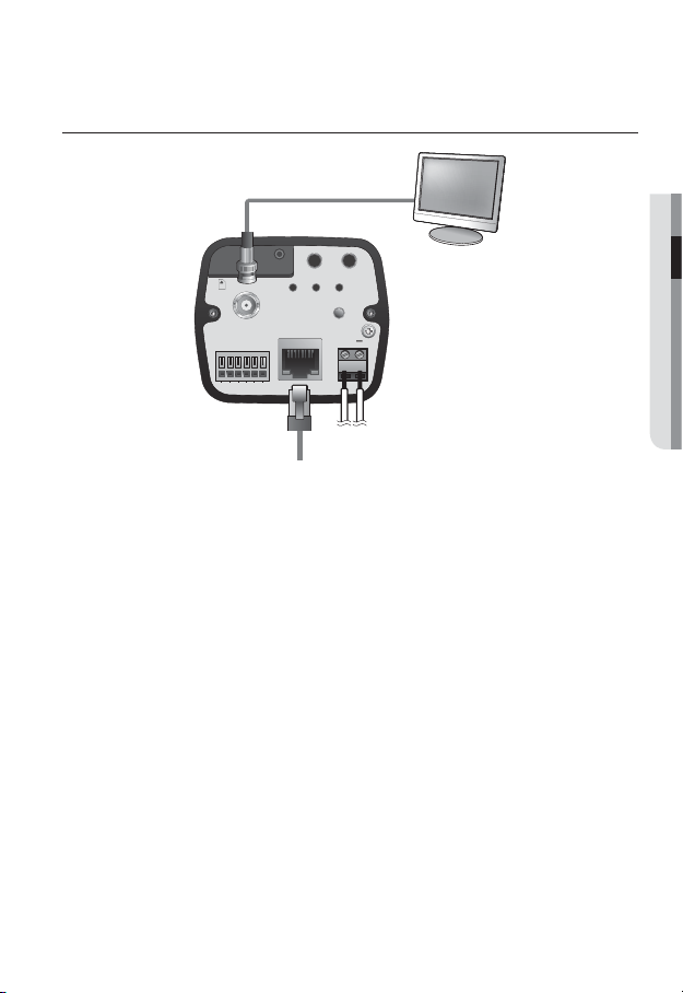
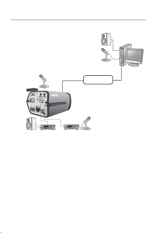
CONNECTING WITH OTHER DEVICE
● INSTALLATION & CONNECTION
SD CARD
SD CARDSD CARD
VIDEO
1: ALARM OUT 4 : GND
2: ALARM IN 5 : RS-485+
3: ALARM COM
6: RS-485-
1 2 3 4 5 6
AUDIO OUT
SD SYSTEM POWER
NETWORK
ACT
LINK
RESET
AUDIO IN
GND
+
DC 12V
Monitor
Power
Ethernet
Connecting to the monitor
Connect the video out port of the camera to the video input port of the monitor.
In the initial installation of the camera, you can connect the camera to the monitor for checking
M
the connection status.
You must set <Video output> to <On> before the display screen can be activated. (page 43)
You can set the video output type to either NTSC or PAL. (page 43)
Ethernet Connection
Connect the Ethernet cable to the local network or to the Internet.
Power Supply
Use the screwdriver to connect each line (+, –) of the power cable to the corresponding
power port of the camera.
Be careful not to reverse the polarity when you connect the power cable.
J
You can also use a router featuring PoE (Power over Ethernet) to supply power to the camera.
If PoE and DC 12V are both applied, this camera will get supplied with power from PoE.
Please make sure the monitor and camera are turned off when connecting them.
English _17
installation & connection
Connecting to Audio Input/Output
Speaker
Microphone
Microphone
VID
EO
GND
1
:
ALARM OUT 4 :
N
ETW
2
:
GND
ALARM IN
O
RK
5
:
RS-485+
3
:
ALARM COM
6
:
RS-485-
1
2
3
456
ACT
LINK
Network
PC
Speaker Amp Microphone
Connect the AUDIO IN port of the camera with the microphone directly or LINE OUT
1.
Amp
port of the amplifier that the microphone is connected to.
Connect the AUDIO OUT port of the camera with the LINE IN port of the speaker.
2.
Check the specifications for audio input.
3.
Audio Codec
•
G.711 PCM. μ-law 64kbps 8kHz sampling
Full duplex Audio
•
Audio in
•
Used for mono signal line input (Max.2.4 Vpp)
Audio out
•
Used for mono signal line output (Max.2.4 Vpp)
Line out impedance
•
600
18_ installation & connection
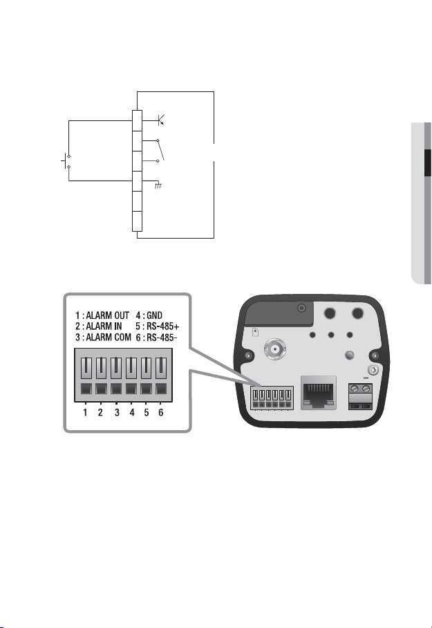
Alarm I/O Wiring Diagram
ALARM OUT
1
(5mA sink)
ALARM IN
2
(30VDC 2A,
125VAC 0.5A MAX)
3
ALARM COM
GND
4
5
RXTX+
RXTX-
6
Connecting to the I/O port box
Connect the Alarm I/O signal to the corresponding port of the rear port box.
SD CARD
SD CARDSD CARD
VIDEO
1 : ALARM OUT 4 : GND
2 : ALARM IN 5 : RS-485+
3 : ALARM COM
6 : RS-485-
AUDIO OUT
SD SYSTEM POWER
RESET
NETWORK
● INSTALLATION & CONNECTION
AUDIO IN
GND
+
1 2 3 4 5 6
•
ALARM OUT : Used to connect the alarm output signal.
•
ALARM IN : Used to connect the alarm input signal.
•
ALARM COM : Common port where the alarm output signal is connected.
•
GND : Used for earth-grounding.
•
RS-485+ : Communication port for RS-485 receiver (+).
•
RS-485- : Communication port for RS-485 receiver (-).
ACT
DC 12V
LINK
Connecting an external RS-485 device
Connect the camera with an external device using the [RS-485 +, -] ports.
You can control the pan/tilt operations of the camera via RS-485 communications.
English _19
network connection and setup
You can set up the network settings according to your network configurations.
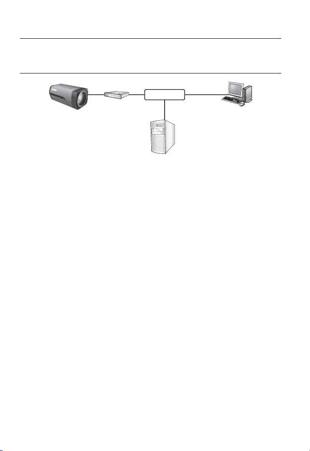
CONNECTING THE CAMERA DIRECTLY TO LOCAL AREA
NETWORKING
Connecting to the camera from a local PC in the LAN
Launch an Internet browser on the local PC.
1.
Enter the IP address of the camera in the address bar of the browser.
2.
Camera
Camera
Switch
HUB
Firewall
INTERNET
External Remote PC
Local PC
<Local Network>
A remote PC in an external Internet out of the LAN network may not be able to connect to the
M
camera installed in the intranet if the port-forwarding is not properly set or a firewall is set.
In this case, to resolve the problem, contact your network administrator.
By factory default, the IP address will be assigned from the DHCP server automatically. If there is
no DHCP server available, the IP address will be set to 192.168.1.100.
To change the IP address, use the IP Installer.
For further details on IP Installer use, refer to “Static IP Setup”. (Page 25)
20_ network connection and setup
DDNS Server
(Data Center, KOREA)
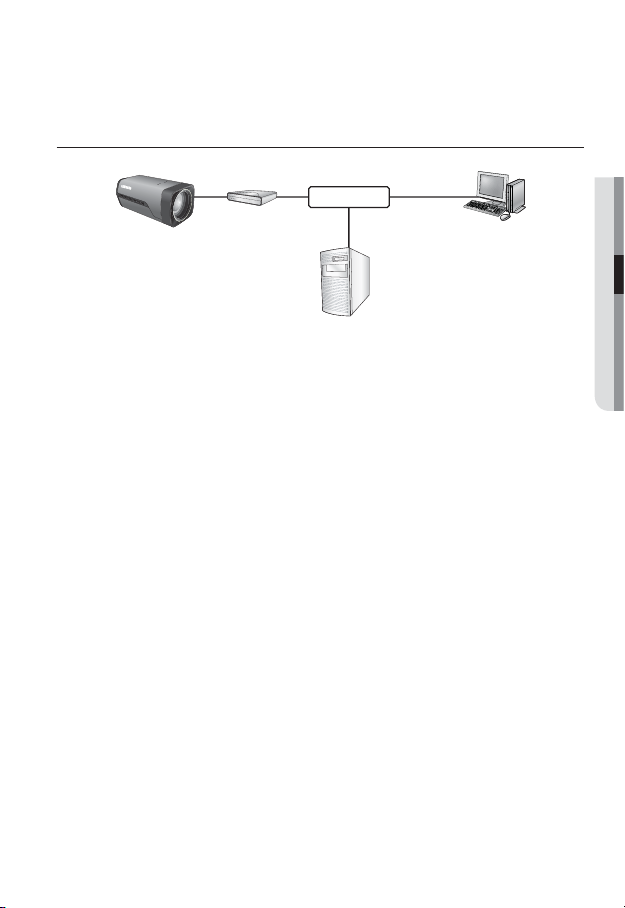
CONNECTING THE CAMERA DIRECTLY TO A DHCP
BASED DSL/CABLE MODEM
DSL/Cable
Camera
Use the cross LAN cable to connect the network cable directly to your PC.
1.
Run the IP Installer and change the IP address of the camera so that you can use
2.
Modem
INTERNET
DDNS Server
(Data Center, KOREA)
External Remote PC
the web browser on your desktop to connect to the Internet.
Use the Internet browser to connect to the camera.
3.
Move to [Setup] page.
4.
Move to [Network] – [DDNS] and configure the DDNS settings.
5.
Move to [Network] – [Interface], and set the network type to [DHCP].
6.
Connect the camera, which was removed from your PC, directly to the modem.
7.
Restart the camera.
8.
For registering the DDNS settings, refer to “Registering with DDNS”. (page 53)
M
For configuring the DDNS settings, refer to “DDNS”. (page 52)
For setting the network type, refer to “Interface”. (page 51)
●
NETWORK CONNECTION AND SETUP
English _21
network connection and setup
CONNECTING THE CAMERA DIRECTLY TO A PPPoE
MODEM
PPPoE Modem
Camera
Use the cross LAN cable to connect the network cable directly to your PC.
1.
Run the IP Installer and change the IP address of the camera so that you can use
2.
the web browser on your desktop to connect to the Internet.
Use the Internet browser to connect to the camera.
3.
Move to [Setup] page.
4.
Move to [Network] – [DDNS] and configure the DDNS settings.
5.
Move to [Network] – [Interface], and set the network type to [PPPoE].
6.
Connect the camera, which was removed from your PC, directly to the modem.
7.
Restart the camera.
8.
For registering the DDNS settings, refer to “Registering with DDNS”. (page 53)
M
For configuring the DDNS settings, refer to “DDNS”. (page 52)
For setting the network type, refer to “Interface”. (page 51)
INTERNET
DDNS Server
(Data Center, KOREA)
External Remote PC
22_ network connection and setup
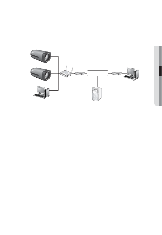
CONNECTING THE CAMERA TO A BROADBAND ROUTER
WITH THE PPPoE/CABLE MODEM
This is for a small network environment such as homes, SOHO and ordinary shops.
Camera
●
NETWORK CONNECTION AND SETUP
INTERNET
PPPoE or
Cable Modem
DDNS Server
(Data Center, KOREA)
External Remote
PC
Camera
Local PC
Broadband
Router
PPPoE or
Cable Modem
Configuring the network settings of the local PC connected to a
Broadband Router
Configuring the network settings of the local PC connected to a Broadband Router, follow
the instructions below.
Select : <Network Neighborhood> <Properties> <Local Area Connection>
•
<Properties> <General> <Internet Protocol (TCP/IP)> <Properties>
<Obtain an IP address automatically> or <Use the following IP address>.
•
Follow the instructions below if you select <Use the following IP address>:
ex1) If the address (LAN IP) of the Broadband Router is 192.168.1.1
IP address : 192.168.1.100
Subnet Mask : 255.255.255.0
Default Gateway : 192.168.1.1
ex2) If the address (LAN IP) of the Broadband Router is 192.168.0.1
IP address : 192.168.0.100
Subnet Mask : 255.255.255.0
Default Gateway : 192.168.0.1
ex3) If the address (LAN IP) of the Broadband Router is 192.168.xxx.1
IP address : 192.168.xxx.100
Subnet Mask : 255.255.255.0
Default Gateway : 192.168.xxx.1
For the address of the Broadband Router, refer to the product’s documentation.
M
Refer to the “Port Range Forward (Port Mapping) Setup” section of the Broadband Router’s
documentation. (Page 29)
English _23
network connection and setup
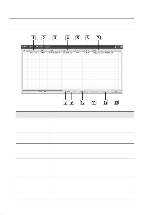
BUTTONS USED IN IP INSTALLER
Item Description
Device Name
Mode
b
MAC(Ethernet)
c
Address
IP Address
Protocol
UPnP Status This function is not currently implemented.
Model name of the connected camera.
Click the column to sort the list by model name.
However, search will be stopped if clicked during the search.
Displays either <Static> or <Dynamic> for the current network connection
status.
Ethernet address for the connected camera.
Click the column to sort the list by Ethernet address.
However, search will be stopped if clicked during the search.
IP address.
Click the column to sort the list by IP address.
However, search will be stopped if clicked during the search.
The factory default is “192.168.1.100”.
Network setting for the camera.
The factory default is “IPv4”.
Cameras with the IPv6 setting will be displayed “IPv6”.
24_ network connection and setup

Item Description
URL
IPv4 Scans for cameras with the IPv4 setting.
IPv6 Scans for cameras with the IPv6 setting.
Search
Auto Set The IP Installer automatically configures the network settings.
Manual Set You should configure the network settings manually.
Exit Exits the IP Installer program.
m
For the IP installer, use only the installer version provided in the installation DVD or use the latest
M
one if available. You can download the latest version from the product website.
DDNS URL address enabling access from the external Internet.
However, this will be replaced with the <IP Address> of the camera if
DDNS registration has failed.
Scans for cameras that are currently connected to the network.
However, this button will be grayed out if neither IPv4 nor IPv6 is checked.
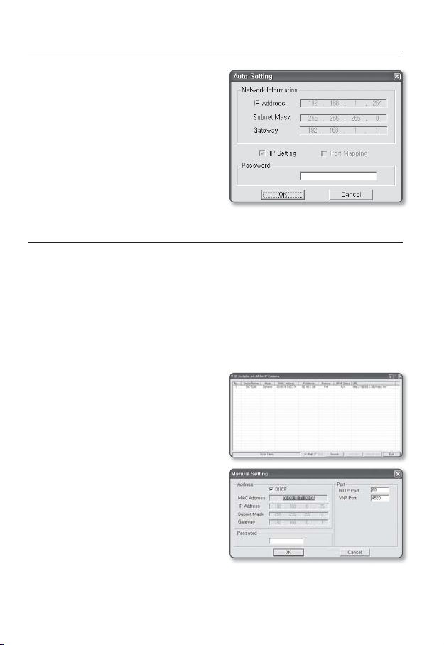
STATIC IP SETUP
Manual Network Setup
Run <IP Installer_vX.XX.exe> to display the camera search list.
At the initial startup, both [Auto Set] and [Manual Set] will be grayed out.
For cameras found with the IPv6 setting, these buttons will be grayed out as the cameras do not
M
support this function.
1.
Select a camera in the search list.
Find the MAC (Ethernet) address
labeled on the rear of the camera.
Both the [Auto Set] and [Manual Set]
buttons will be activated.
2.
Click [Manual Set].
The Manual Setting dialog appears.
The default values of <IP Address>,
<Subnet Mask>, <Gateway>, <HTTP Port> and <VNP Port> of the camera will
be displayed.
●
NETWORK CONNECTION AND SETUP
English _25
network connection and setup
In the <Address> pane, provide the
3.
necessary information.
MAC (Ethernet) Address : The MAC
•
(Ethernet) address of the applicable
camera will be set automatically so
you don't need to input it manually.
You can configure the static IP settings
M
only if the DHCP checkbox is unchecked.
If using a Broadband Router
IP Address : Enter an address falling in
•
the IP range provided by the Broadband
Router.
ex) 192.168.1.2~254,
192.168.0.2~254,
192.168.XXX.2~254
•
Subnet Mask : The <Subnet Mask>
of the Broadband Router will be the
<Subnet Mask> of the camera.
•
Gateway : The <Local IP Address> of
the Broadband Router will be the <Gateway> of the camera.
The settings may differ depending on the connected Broadband Router model.
M
For more information, refer to the user manual of the applicable router.
Refer to the “Port Range Forward (Port Mapping) Setup” section of the Broadband Router’s
documentation. (Page 29)
If not using a Broadband Router
For setting <IP Address>, <Subnet Mask>, and <Gateway>, contact your network administrator.
In the <Port> pane, provide
4.
necessary information.
HTTP Port : Used to access the
•
camera using the Internet browser,
defaulted to 80. Use the spin button
to change the HTTP Port value.
VNP Port : Used to control the video
•
signal transfer, defaulted to 4520.
Enter the password.
5.
This is the login password for the “admin” user who accesses the camera.
The default password is “4321”.
26_ network connection and setup

Click [OK].
6.
Manual network setup will be completed.
7.
When the manual setup including IP is completed, the camera will restart.
If the Broadband Router has more than one camera connected
Configure the IP related settings and the Port related settings distinctly with each other.
Category Camera #1 Camera #2
●
NETWORK CONNECTION AND SETUP
IP related settings
Port related settings
If the <HTTP Port> is set other than 80, you must provide the <Port> number in the address bar
M
of the Internet browser before you can access the camera.
ex) http://IP address : HTTP Port
IP Address
Subnet Mask
Gateway
HTTP Port
VNP Port
http://192.168.1.100:8080
192.168.1.100
255.255.255.0
192.168.1.1
8080
4520
192.168.1.101
255.255.255.0
192.168.1.1
8081
4521
Auto Network Setup
Run <IP Installer_vX.XX.exe> to display the camera search list.
At the initial startup, both [Auto Set] and [Manual Set] will be grayed out.
For cameras found with the IPv6 setting, these buttons will be grayed out as the cameras do not
M
support this function.
1.
Select a camera in the search list.
Find the MAC (Ethernet) address
labeled on the rear of the camera.
Both the [Auto Set] and [Manual Set]
buttons will be activated.
2.
Click [Auto Set].
The Auto Setting dialog appears.
The <IP Address>, <Subnet Mask>,
and <Gateway> will be set automatically.
English _27
network connection and setup
Enter the password.
3.
This is the login password for the
“admin” user who accesses the
camera. The default password is
“4321”.
Click [OK].
4.
Auto network setup will be completed.
DYNAMIC IP SETUP
Dynamic IP Environment Setup
Example of the Dynamic IP environment
•
If
a Broadband Router, with cameras connected, is assigned an IP address by the
DHCP server
If connecting the camera directly to modem using the DHCP protocols
If IPs are assigned by the internal DHCP server via the LAN
-
Checking the Dynamic IP
Run the IP Installer on the user’s local
1.
machine to display cameras allocated
with <Dynamic IP> addresses in the
list.
Select a camera in the list, and click
2.
[Manual Set] to check the <Dynamic
IP> of the camera.
If you uncheck <DHCP>, you can
change IP to <Static>.
28_ network connection and setup
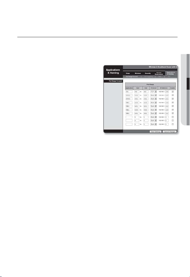
PORT RANGE FORWARD (PORT MAPPING) SETUP
If you have installed a Broadband Router with a camera connected, you must set the port range
forwarding on the Broadband Router so that a remote PC can access the camera in it.
Manual Port Range Forwarding
From the Setup menu of the Broadband
1.
Router, select <Applications &
Gaming> - <Port Range Forward>.
For setting the port range forward for
a third-party Broadband Router, refer
to the user guide of that Broadband
Router.
Select <TCP> and <UDP Port>
2.
for each connected camera to the
Broadband Router.
Each port number for the Broadband
Router should match that specified in
<Network> - <Port> from the
camera's Setup menu.
When done, click [Save Settings].
3.
Your settings will be saved.
Above sample instructions are based on the CISCO’s Broadband Router (Model: LINKSYS).
M
The settings may differ depending on the connected Broadband Router model.
For more information, refer to the user manual of the applicable router.
●
NETWORK CONNECTION AND SETUP
English _29
network connection and setup
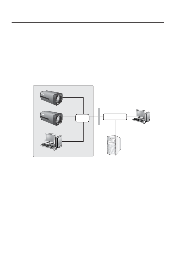
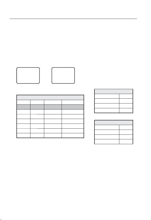
Setting up Port Range Forward for several network cameras
When several network cameras are connected to one Broadband Router device, you
should forward the TCP 943 port of the router to the TCP 943 port of a connected camera.
If you don't set properly the TCP 943 port of the router, you cannot get any video stream from the
J
web page of the camera.
•
TCP 943 port is a port for the Silverlight policy server of a camera.
When Camera1 and Camera2 are connected to a router :
User Internet
Start End Protocol IP Address
943 943 TCP 192.168.1.100
3000 3000 TCP/UDP 192.168.1.100
3001 3001 TCP/UDP 192.168.1.101
4520 4520 TCP/UDP 192.168.1.100
4521 4521 TCP/UDP 192.168.1.101
8080 8080 TCP/UDP 192.168.1.100
8081 8081 TCP/UDP 192.168.1.101
You can set a rule of Port Forwarding on the Broadband Router device through its
•
configuration web page.
You cannot change the Silverlight policy server port of a camera.
•
You can change the ports of the camera except the policy server port through its
•
configuration web pages.
30_ network connection and setup
Ù
Broadband Router
Ú
Camera1 (192.168.1.100)
Web Server Port 8080
Ù
Policy Server Port 943
Camera2 (192.168.1.101)
Web Server Port 8081
Ù
Policy Server Port 943
VNP Port 4520
RTSP Port 3000
VNP Port 4521
RTSP Port 3001
 Loading...