

Page 1

NETWORK CAMERA
User Manual
SNB-5000/SND-5080/
SND-5080F/SNV-5080
Page 2

Network Camera
User Manual
Copyright
©2010 Samsung Techwin Co., Ltd. All rights reserved.
Trademark
The name of this product is the registered trademark of Samsung Techwin Co., Ltd.
Other trademarks mentioned in this manual are the registered trademark of their respective company.
Restriction
Samsung Techwin Co., Ltd shall reserve the copyright of this document. Under no circumstances, this
document shall be reproduced, distributed or changed, partially or wholly, without formal authorization of
Samsung Techwin.
Disclaimer
Samsung Techwin makes the best to verify the integrity and correctness of the contents in this document, but
no formal guarantee shall be provided. Use of this document and the subsequent results shall be entirely on
the user’s own responsibility. Samsung Techwin reserves the right to change the contents of this document
without prior notice.
Warranty
If the product does not operate properly in normal conditions, please let us know. Samsung Techwin will resolve
the problem for free of charge. The warranty period is 3 years. However, the followings are excluded:
If the system behaves abnormally because you run a program irrelevant to the system operation.
•
Deteriorated performance or natural worn-out in process of time
•
is the registered logo of Samsung Techwin Co., Ltd.
Page 3
overview
IMPORTANT SAFETY INSTRUCTIONS
Read these instructions.
1.
Keep these instructions.
2.
Heed all warnings.
3.
Follow all instructions.
4.
Do not use this apparatus near water.
5.
Clean only with dry cloth.
6.
Do not block any ventilation openings, Install in accordance with the manufacturer’s
7.
instructions.
Do not install near any heat sources such as radiators, heat registers, stoves, or other
8.
apparatus (including amplifiers) that produce heat.
Do not defeat the safety purpose of the polarized or grounding-type plug. A polarized
9.
plug has two blades with one wider than the other. A grounding type plug has two
blades and a third grounding prong. The wide blade or the third prong are provided for
your safety, If the provided plug does not fit into your outlet, consult an electrician for
replacement of the obsolete outlet.
Protect the power cord from being walked on or pinched particularly at plugs, conve-
10.
nience receptacles, and the point where they exit from the apparatus.
Only use attachments/ accessories specified by the manufacturer.
11.
Use only with the cart, stand, tripod, bracket, or table specified by
12.
the manufacturer, or sold with the apparatus. When a cart is used,
use caution when moving the cart/apparatus combination to avoid
injury from tip-over.
Unplug this apparatus during lighting storms or when unused for
13.
long periods of time.
Refer all servicing to qualified service personnel. Servicing is required when the apparatus
14.
has been damaged in any way, such as power-supply cord or plug is damaged, liquid has
been spilled or objects have fallen into the apparatus, the apparatus has been exposed to
rain or moisture, does not operate normally, or has been dropped.
● OVERVIEW
English _3
Page 4
overview
WARNING
TO REDUCE THE RISK OF FIRE OR ELECTRIC SHOCK, DO NOT EXPOSE
THIS PROCUCT TO RAIN OR MOISTURE. DO NOT INSERT ANY METALLIC
OBJECT THROUGH THE VENTILATION GRILLS OR OTHER OPENNINGS
ON THE EQUIPMENT.
Apparatus shall not be exposed to dripping or splashing and that no objects
filled with liquids, such as vases, shall be placed on the apparatus.
CAUTION
CAUTION
RISK OF ELECTRIC SHOCK.
DO NOT OPEN
CAUTION
REFER SERVICING TO QUALIFIED SERVICE PERSONNEL.
: TO REDUCE THE RISK OF ELECTRIC SHOCK.
DO NOT REMOVE COVER (OR BACK).
NO USER SERVICEABLE PARTS INSIDE.
EXPLANATION OF GRAPHICAL SYMBOLS
The lightning flash with arrowhead symbol, within an
equilateral triangle, is intended to alert the user to the
presence of “dangerous voltage” within the product’s
enclosure that may be of sufficient magnitude to constitute a
risk of electric shock to persons.
The exclamation point within an equilateral triangle is intended
to alert the user to the presence of important operating
and maintenance (servicing) instructions in the literature
accompanying the product.
4_ overview
Page 5

Class construction
An apparatus with CLASS construction shall be connected to a MAINS
socket outlet with a protective earthing connection.
Battery
Batteries(battery pack or batteries installed) shall not be exposed to excessive
heat such as sunshine, fire or the like.
Disconnection Device
Disconnect the main plug from the apparatus, if it’s defected. And please call
a repair man in your location.
When used outside of the U.S., it may be used HAR code with fittings of
an approved agency is employed.
CAUTION
These servicing instructions are for use by qualified service personnel only.
To reduce the risk of electric shock do not perform any servicing other than
that contained in the operating instructions unless you are qualified to do so.
The BNC output port is used to monitor the installation process of the
network camera.
If you keep the BNC cable connected, a risk of lightening may cause damage
or malfunction to the product.
Please use the input power with just one camera and other devices must not
be connected.
● OVERVIEW
English _5
Page 6
overview
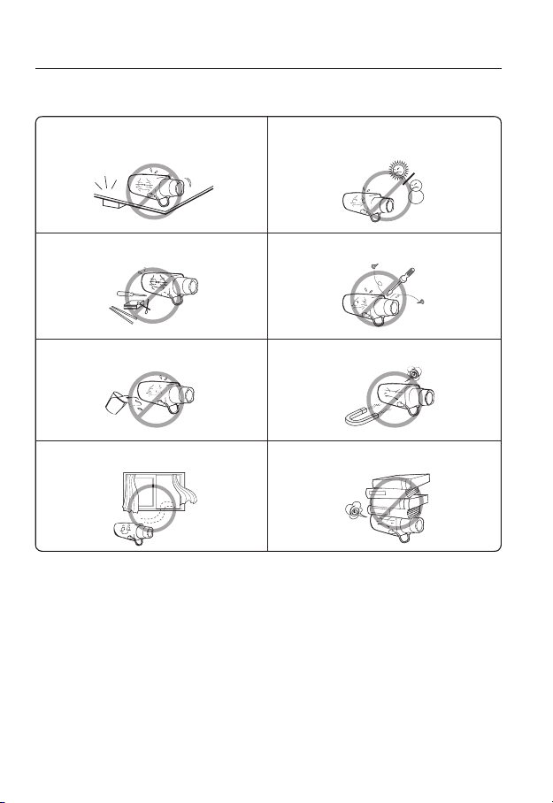
Please read the following recommend safety precautions carefully.
Do not Place this apparatus on an uneven surface. Do not install on a surface where it is exposed to direct
Do not place this apparatus near. Do not attempt to service this apparatus yourself.
Do not place a glass of water on the product. Do not install near any magnetic sources.
Do not block any ventilation openings. Do not place heavy items on the product.
User’s Manual is a guidance book how to use the products
The meaning of the using sign in the book is following
Reference : In case of providing information for helping of product’s usages
Notice : If there’s any possibility to occur any damages for the goods and
human caused by not following the instruction
Please read this manual for the safety before using of goods and keep it in
the safe place.
sunlight, near heating equipment or heavy cold area.
6_ overview
Page 7
This equipment has been tested and found to comply with the limits for a
Class A digital device, pursuant to part 15 of the FCC Rules. These limits are
designed to provide reasonable protection against harmful interference when
the equipment is operated in a commercial environment.
This equipment generates, uses, and can radiate radio frequency energy and,
if not installed and used in accordance with the instruction manual, may cause
harmful interference to radio communications. Operation of this equipment in a
residential area is likely to cause harmful interference in which case the user will
be required to correct the interference at his own expense.
Samsung Techwin cares for the environment at all product manufacturing stages, and is
taking measures to provide customers with more environmentally friendly products.
The Eco mark represents Samsung Techwin’s devotion to creating environmentally friendly
products, and indicates that the product satisfies the EU RoHS Directive.
Correct Disposal of This Product (Waste Electrical & Electronic Equipment)
(Applicable in the European Union and other European countries with separate collection
systems)
This marking on the product, accessories or literature indicates that the product and its
electronic accessories (e.g. charger, headset, USB cable) should not be disposed of with other
household waste at the end of their working life. To prevent possible harm to the environment
or human health from uncontrolled waste disposal, please separate these items from other
types of waste and recycle them responsibly to promote the sustainable reuse of material
resources.
Household users should contact either the retailer where they purchased this product, or
their local government office, for details of where and how they can take these items for
environmentally safe recycling.
Business users should contact their supplier and check the terms and conditions of the
purchase contract. This product and its electronic accessories should not be mixed with other
commercial wastes for disposal.
● OVERVIEW
English _7
Page 8

overview
CONTENTS
OVERVIEW
3
INSTALLATION & CONNEC-
TION
25
NETWORK CONNECTION
AND SETUP
44
3 Important Safety Instructions
10 Product Features
10 Recomended PC Specifications
11 What’s Included
13 At a Glance (SNB-5000)
16 At a Glance (SND-5080)
19 At a Glance (SND-5080F)
22 At a Glance (SNV-5080)
25 Installation (SND-5080)
27 Installation (SND-5080F)
29 Installation (SNV-5080)
34 Mounting the Lens
35 Inserting/Removing an SD
Memory Card
38 Memory Card Information (Not
Included)
39 Connecting with other Device
44 Connecting the Camera Directly
to Local Area Networking
45 Connecting the Camera Directly
to a DHCP Based DSL/Cable
Modem
46 Connecting the Camera Directly
to a PPPoE Modem
47 Connecting the Camera to an
IP Router with the PPPoE/Cable
Modem
48 Buttons used in IP Installer
49 Static IP Setup
52 Dynamic IP Setup
53 Port Range Forward (Port
Mapping) Setup
55 Connecting to the Camera from a
Shared Local PC
55 Connecting to the Camera from a
Remote PC via the Internet
8_ overview
Page 9

WEB VIEWER
56
56 Connecting to the Camera
57 Login
58 Installing Silverlight Runtime
60 Using the Live Screen
62 Playback
64 Playing the backup recordings
● OVERVIEW
CAMERA SETUP
65
SETUP SCREEN
74
APPENDIX
92
65 Using the Camera Menu
65 Camera Menu Setup
74 Setup
74 Audio & Video Setup
77 Network Setup
82 Event Setup
88 System Setup
92 Camera Specification
94 Network Specification
97 Troubleshooting
99 Open Source Announcement
101 GPL/LGPL Software License
English _9
Page 10

overview
PRODUCT FEATURES
HD Video Quality
Supports up to 1.3 mega pixels of HD video quality.
H.264/MPEG-4/MJPEG Multi-Streaming
This network camera supports the H.264/MPEG-4/MJPEG codec and can display videos
in different resolutions and qualities simultaneously with different Codecs.
However, MPEG4 video can not be played on a web page. Use CMS software if you want to play
M
the video on a web page.
Support various communication protocols
Supports TCP/IP, UDP, RTP/RTSP, email, and FTP protocols as well as various
internet protocols such as ARP, HTTP, HTTPS and DHCP.
Web Browser-based Monitoring
Using the Internet web browser to display the image in a local network environment.
Alarm
If an event occurs, the event-related video will be transferred to the FTP/email specified by
the user or saved to the SD memory, or the event signal will be sent to the ALARM OUT
port.
Intelligent Video Analysis
Analyzes the event video according to the user-specified rules to recognize the event.
ONVIF (Spec 1.01) Compliance
This product supports ONVIF Core Spec. 1. 01.
For more information, refer to www.onvif.org.
RECOMENDED PC SPECIFICATIONS
CPU : Intel(R) Core(TM)2 2.00 GHz or higher
Operating System : Windows XP, VISTA, 7
Resolution : 1280X1024 pixels or higher
RAM : 1GB or higher
Web Browser : Internet Explorer 7.0 or higher
Video Memory : 128MB or higher
Mac OS
Firefox, Google Chrome, Safari
10_ overview
Page 11
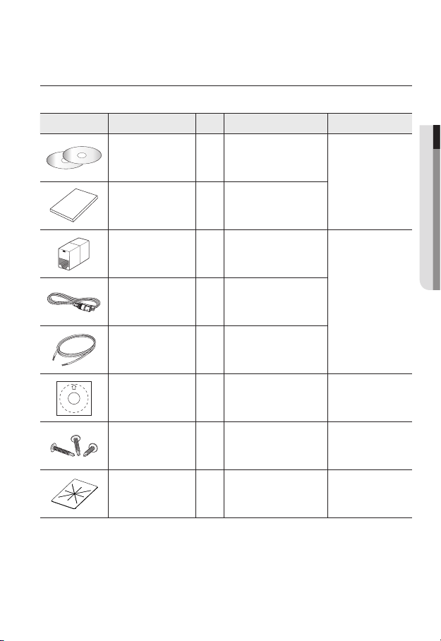
WHAT’S INCLUDED
Please check if your camera and accessories are all included in the product package.
Appearance Item Name
User Manual,
Installer S/W DVD,
CMS S/W DVD
User Manual 1
Jack Modular 1 LAN cable gender
Quantity
2
Description Model Name
SNB-5000
SND-5080/5080F
SNV-5080
● OVERVIEW
Cable for the testing
monitor
Alarm Cable 1 Used to connect to Alarm I/O
Template 1 Product installation guide
Iron Screw 3 Used for fixing to an iron plate SND-5080/5080F
Dustproof Plate 1 Preventing dust inflow SND-5080
Used to test the camera
1
connection to a portable display
device
SND-5080/5080F
SNV-5080
SND-5080F
SNV-5080
English _11
Page 12
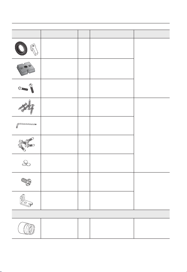
overview
Appearance Item Name
C Mount Adapter
Auto Iris Lens Connector
Camera Holder (Mount) 1
Camera Holder (Mount)
Screws
ASSY-Tapping Screw
L Wrench
Plastic Anchor
Rubber cap 3
Tapping Screw 1
Bracket Safety 1
Quantity
1
2
4
1
4
Description Model Name
Used to install the camera lens
Used to install the camera holder
Used to install the mount
Used for installation on the wall or
Used to remove/fix the dome
For fixing a screw, Inserted in
a hole (reinforced anchoring
Insulation cap for improved
EMC performance.
SNB-5000
ceiling
cover
SNV-5080
force)
SND-5080F
12_ overview
CS/C Lens
Lens Options (not included)
Optional lens to be inserted in a
camera
SNB-5000
Page 13
The Test Monitor Cable is connected to a portable displayer and used for testing the camera.
www.samsungcctv.com
SNB-5000
www.samsungcctv.com
SNB-5000
www.samsungcctv.com
SNB-5000
M
If you intend to use it for an actual monitoring camera, use the BNC cable instead.
For improved EMC performance, it is recommended to use the insulation cap provided as an
accessory.
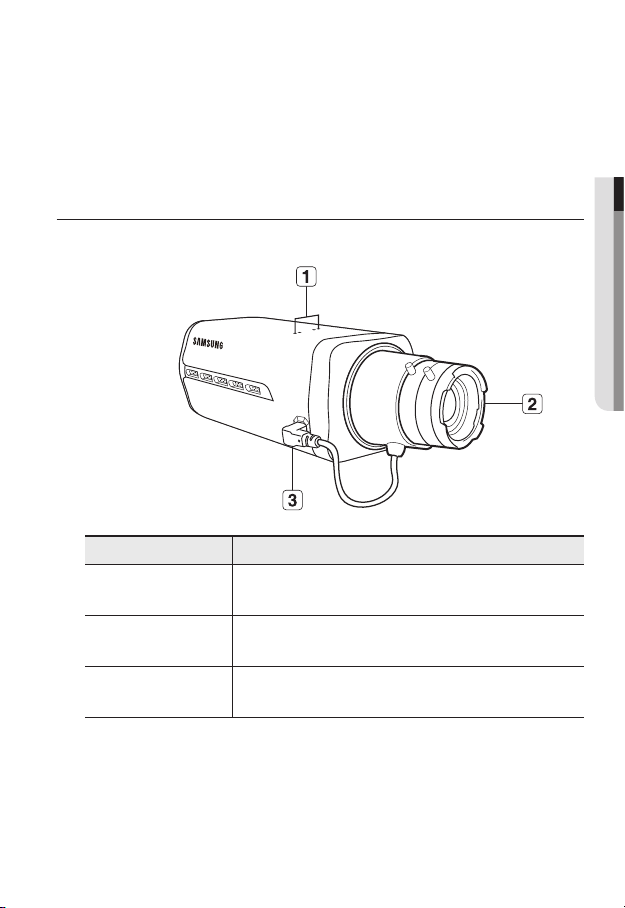
AT A GLANCE (SNB-5000)
Front Side
Item Description
Camera Holder
a
(Mount) Holes
● OVERVIEW
Used when you mount the camera onto the bracket by fixing the camera
holder (mount) adaptor with the bracket.
Auto Iris Lens
b
(Optional)
Auto Iris Lens
c
Connector
Wipe out a dirty surface of the lens softly with a lens tissue or cloth to which you have applied
M
ethanol.
Installed on the lens adaptor.
Used to supply power and output signal to control the iris of the lens.
English _13
Page 14
overview
SD CARD
AUDIO OUT
VIDEO
1 2 3 4 5
SD SYSTEM POWER
RESET
NETWORK
ACT
LINK
GND
1 : ALARM IN 4 :
2 : ALARM OUT 5 : GND
3 : ALARM COM
AC 24V
DC 12V
AUDIO IN
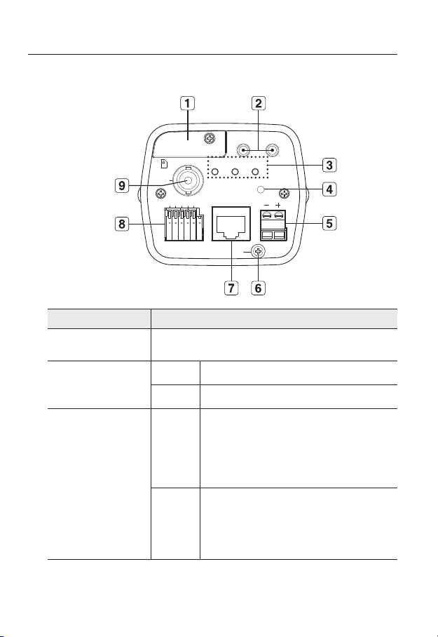
Rear Side
Item Description
SD Memory Card
a
Compartment
Audio terminal
b
System, Power,
c
SD Indicators
Compartment for the SD memory card.
AUDIO OUT Terminal for audio output.
AUDIO IN Terminal for audio input.
SD
SYSTEM
ON : A memory card is inserted and operates normally.
Flashing : Failed to record, insufficient space, or inserted
abnormally.
OFF : Camera is off, camera is restarting, or memory card is
not in place.
ON : The camera is turned on and connected to the network
properly.
Blinking : During DDNS setup, or in case of setup failure, or
in a state of unstable network connection.
OFF : When the system is rebooting, or turned off.
14_ overview
Page 15

System, Power,
c
SD Indicators
Reset Button
d
Power Port Used to plug the power cable.
e
GND Used for earth-grounding.
f
POWER
Resets the camera settings to the default. Press and hold it for about 5
seconds to turn off the system indicator and restart the system.
Resetting the camera IP address, subnet mask, gateway address etc.
J
requires the use of the IP Installer software application.
ON : While the power is on
OFF : If the power is off
● OVERVIEW
g
h
i
Network Port
I/O Port
Video Out Port
Used to connect a PoE or LAN cable.
ALARM IN Used to connect the alarm input signal.
ALARM OUT Used to connect the alarm output signal.
ALARM COM Common port where the alarm output signal is connected.
GND Used for earth-grounding.
Video signal output port connected to the monitor.
English _15
Page 16
overview
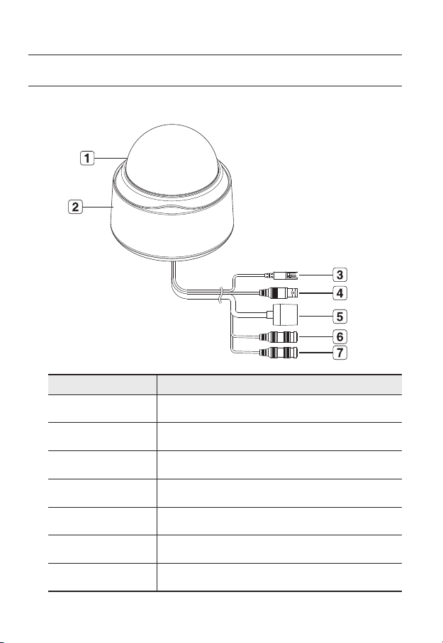
AT A GLANCE (SND-5080)
Appearance
Item Description
Dome Cover Dome cover for the lens and unit protection.
a
Main unit Main unit includes the lens, switch board, PCB boards and screws.
b
Power Port Used to plug the power cable.
c
Video Out Port Video signal output port connected to the monitor.
d
Network Port Used to connect a PoE or LAN cable.
e
Audio In Jack Used to connect to a microphone.
f
Audio Out Jack Used to connect to speakers.
g
16_ overview
Page 17
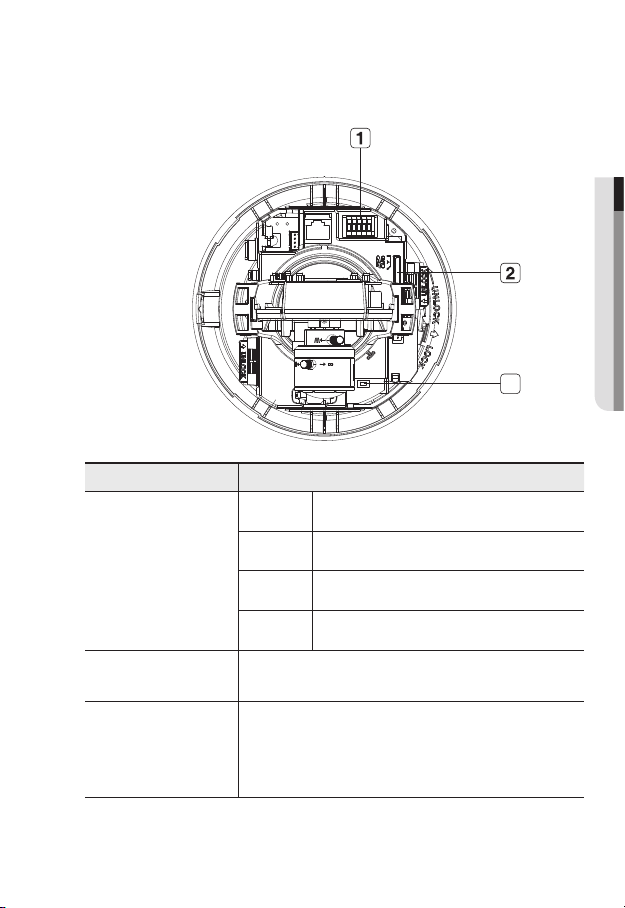
Inside
● OVERVIEW
3
Item Description
ALARM IN Used to connect the alarm input signal.
a
b
c
Alarm In / Out
terminals
SD Memory Card
Compartment
Reset Button
ALARM OUT Used to connect the alarm output signal.
ALARM COM Common port where the alarm output signal is connected.
GND Used for earth-grounding.
Compartment for the SD memory card.
Resets the camera settings to the default. Press and hold it for about 5
seconds to turn off the system indicator and restart the system.
Resetting the camera IP address, subnet mask, gateway address etc.
J
requires the use of the IP Installer software application.
English _17
Page 18
overview
SND-5080-2
SND-5080-3 SND-5080-4
SND-5080-3 SND-5080-4
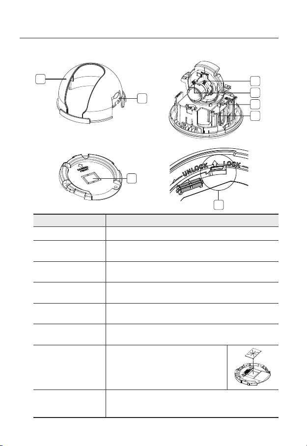
Components
1
2
7
Item Description
Inner Cover Cover for the main unit’s protection.
a
Side wing hooks
b
ZOOM lever
c
Focus lever
d
SD Memory Card
e
Compartment
Monitor Out
f
Wiring Cover
g
Lock Release
h
By lifting it while gently pressing the both ends, you can separate the inner
cover.
Turn the barrel left or right to adjust the zoom, and turn the knob clockwise
to lock the zoom.
Turn the barrel left or right to adjust the focus, and turn the knob clockwise
to lock the focus.
Compartment for the SD memory card.
Using the test monitor cable, you can connect to a mobile display for camera
test.
If you drill a hole in the wiring cover for wiring,
remove the cover and attach the provided dustproof
plate to it, and arrange the cables through the plate.
The dust-proof plate is to prevent outside dust from
inflow to the wiring compartment.
To separate the bracket from the main unit for the installation or to separate
the camera from an installed camera, push this release and turn the main
unit in the marked direction of <UNLOCK>.
3
4
5
6
8
18_ overview
Page 19
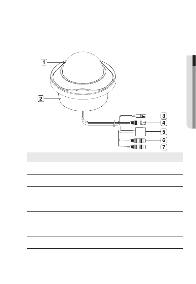
AT A GLANCE (SND-5080F)
Appearance
Item Description
Dome Cover Dome cover for the lens and unit protection.
a
Main unit Main unit includes the lens, switch board, PCB boards and screws.
b
Power Port Used to plug the power cable.
c
Video Out Port Video signal output port connected to the monitor.
d
● OVERVIEW
Network Port Used to connect a PoE or LAN cable.
e
Audio In Jack Used to connect to a microphone.
f
Audio Out Jack Used to connect to speakers.
g
English _19
Page 20
overview
< SND-5080F >
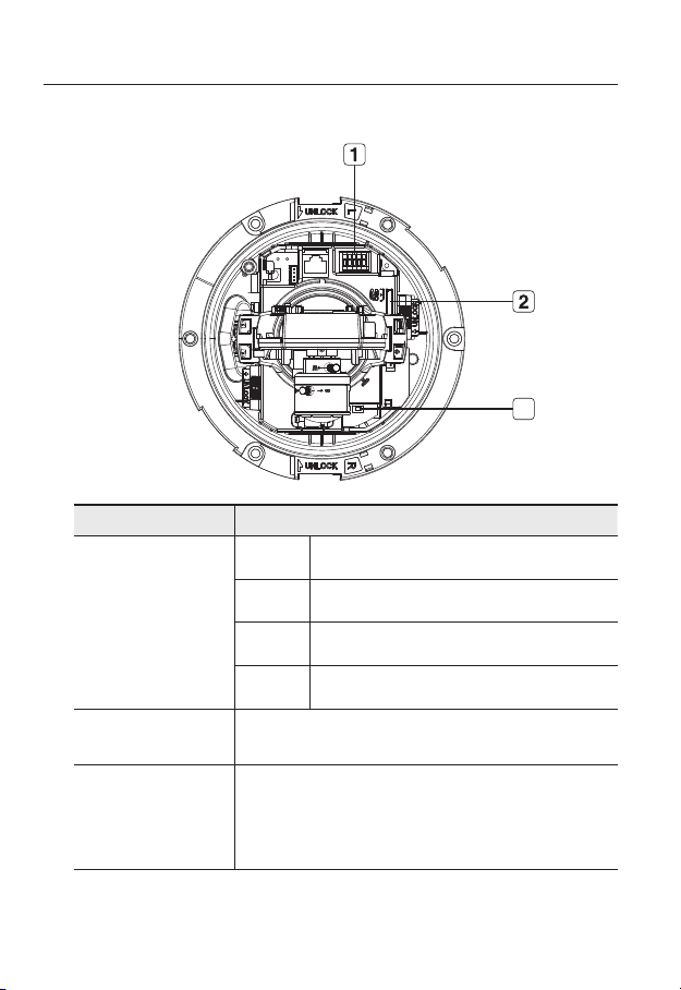
Inside
Item Description
ALARM IN Used to connect the alarm input signal.
3
Alarm In / Out
a
terminals
SD Memory Card
b
Compartment
Reset Button
c
20_ overview
ALARM OUT Used to connect the alarm output signal.
ALARM COM
GND Used for earth-grounding.
Compartment for the SD memory card.
Resets the camera settings to the default. Press and hold it for about 5
seconds to turn off the system indicator and restart the system.
J
Common port where the alarm output signal is connected.
Resetting the camera IP address, subnet mask, gateway address etc.
requires the use of the IP Installer software application.
Page 21
Components
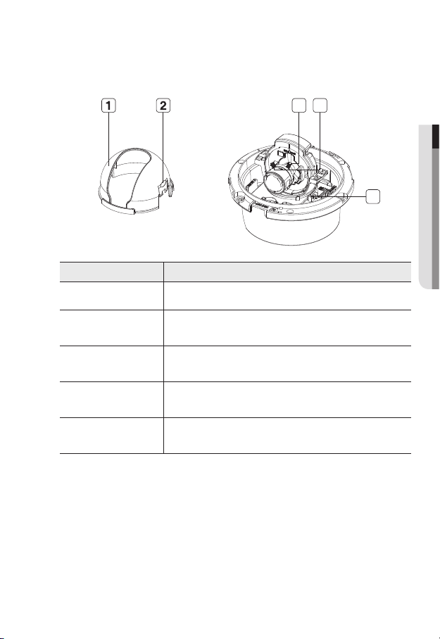
Item Description
Inner Cover Cover for the main unit’s protection.
a
b
Side wing hooks
By lifting it while gently pressing the both ends, you can separate the inner
cover.
3 4
● OVERVIEW
5
c
d
e
ZOOM lever
Focus lever
Monitor Out
Turn the barrel left or right to adjust the zoom, and turn the knob clockwise
to lock the zoom.
Turn the barrel left or right to adjust the focus, and turn the knob clockwise
to lock the focus.
Using the test monitor cable, you can connect to a mobile display for camera
test.
English _21
Page 22

overview
AT A GLANCE (SNV-5080)
Appearance
Item Description
Dome Cover Dome cover for the lens and unit protection.
a
Main unit Main unit includes the lens, switch board, PCB boards and screws.
b
Power Port Used to plug the power cable.
c
Video Out Port Video signal output port connected to the monitor.
d
Network Port Used to connect a PoE or LAN cable.
e
Audio In Jack Used to connect to a microphone.
f
Audio Out Jack Used to connect to speakers.
g
22_ overview
Page 23
Inside
< SNV-5080 >
● OVERVIEW
3
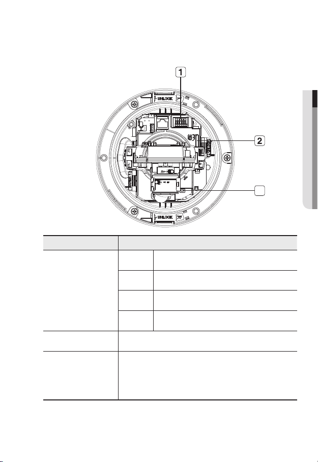
Item Description
ALARM IN Used to connect the alarm input signal.
Alarm In / Out
a
terminals
SD Memory Card
b
Compartment
Reset Button
c
ALARM OUT Used to connect the alarm output signal.
ALARM COM
GND Used for earth-grounding.
Compartment for the SD memory card.
Resets the camera settings to the default. Press and hold it for about 5
seconds to turn off the system indicator and restart the system.
Resetting the camera IP address, subnet mask, gateway address etc.
J
requires the use of the IP Installer software application.
Common port where the alarm output signal is connected.
English _23
Page 24
overview
Components
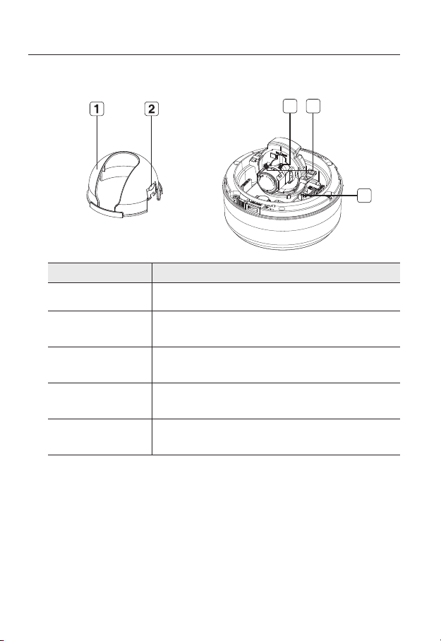
Item Description
Inner Cover Cover for the main unit’s protection.
a
Side wing hooks
b
3 4
5
By lifting it while gently pressing the both ends, you can separate the inner
cover.
ZOOM lever
c
Focus lever
d
Monitor Out
e
24_ overview
Turn the barrel left or right to adjust the zoom, and turn the knob clockwise
to lock the zoom.
Turn the barrel left or right to adjust the focus, and turn the knob clockwise
to lock the focus.
Using the test monitor cable, you can connect to a mobile display for camera
test.
Page 25
installation & connection
INSTALLATION (SND-5080)
Precautions before installation
Ensure you read out the following instructions before installing the camera:
Select an installation site (ceiling or wall) that can endure at least 5 times of the camera
weight.
Stuck-in or peeled-off cables can cause damage to the product or a fire.
For safety purposes, keep anyone else away from the installation site.
And put aside personal belongings from the site, just in case.
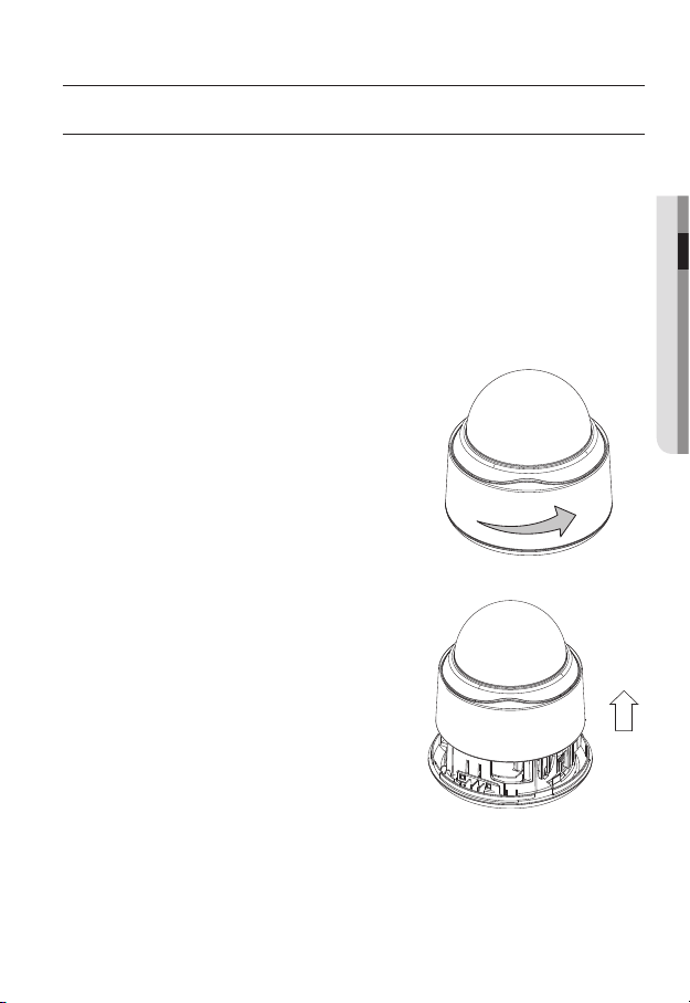
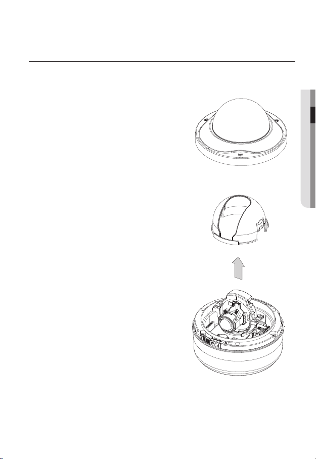
Installing the camera
Hold down the bottom lock lever while
1.
removing the cover with the other hand.
Removing the cover reveals the main unit
and inner cover.
● INSTALLATION & CONNECTION
English _25
Page 26
installation & connection
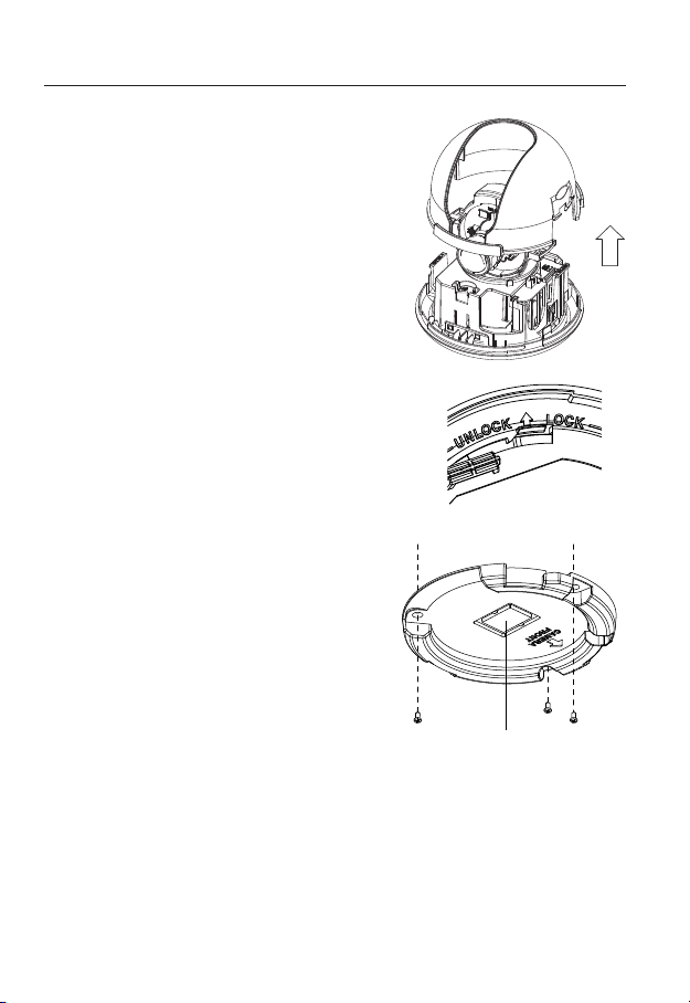
To fix the camera position, hold down either
2.
hook of the inner cover and lift it up.
Push the release lock out while turning the main unit in
3.
the <UNLOCK> direction to remove the bracket.
If this doesn't work, use the hole on the bottom of the
bracket to turn the bracket in the <LOCK> direction.
Use the provided screws (x3) to fix the bracket to a
4.
desired position (ceiling or wall).
Ensure that the <CAMERA FRONT> label on the bracket faces
the direction for camera monitoring.
Arrange the cables through the bracket to the
5.
ceiling or wall.
If you drill a hole in the ceiling cover for wiring,
press hard to remove the cover and attach the
dust-proof plate to it, and arrange the cables
through the plate. If you intend to arrange the
cables without drilling a hole, use the empty
area opposite to the <CAMERA FRONT>
label side for the wiring purpose.
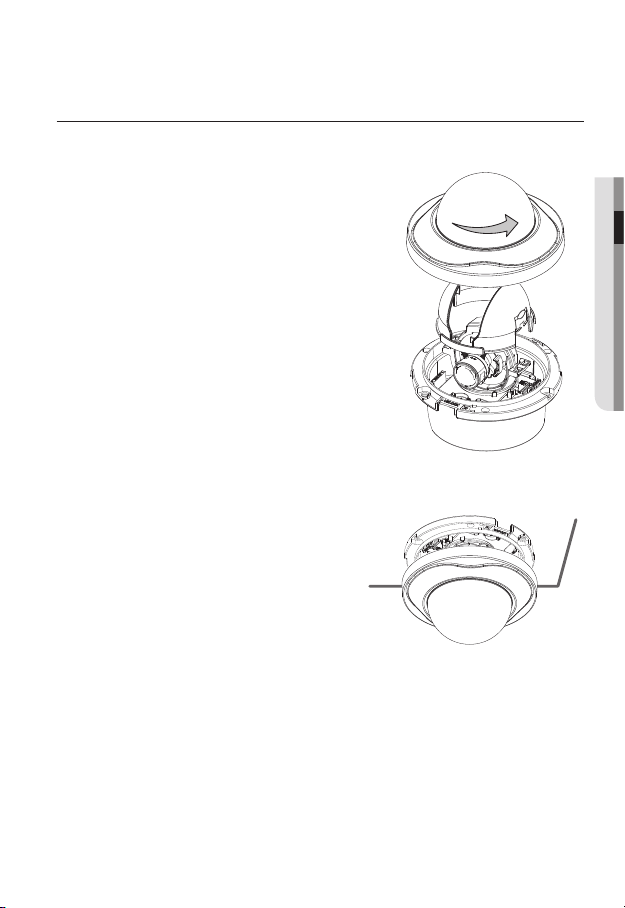
Mount the main unit onto the bracket.
6.
Align the marking hole of the main unit with the
<CAMERA FRONT> label of the bracket, and
turn the unit in the <LOCK> direction.
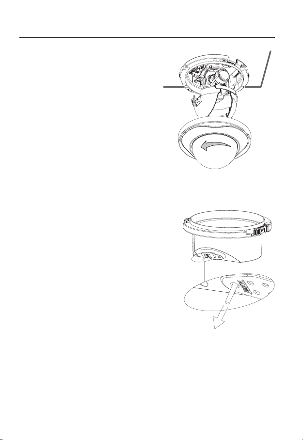
Adjust the lens in a desired direction.
7.
For adjusting the lens direction, refer to “Adjusting the monitoring direction for
the camera”. (page 33)
Secure the inner cover to the main unit.
8.
Fit the two holes of the wing-side locks on the inner cover into the corresponding
hole of the main unit, and press it down until you hear a click.
Fix the cover to the main unit.
9.
Fit the protruding part inside the cover into the corresponding hole of the main unit,
and turn the cover to fix it.
26_ installation & connection
Wiring Cover
Page 27
INSTALLATION (SND-5080F)
Removing the dome cover
Hold down the bottom lock lever while removing
1.
the cover with the other hand. Removing the
cover reveals the main unit and inner cover.
To fix the camera position, hold down both
2.
hooks of the inner cover while lifting it up.
Ceiling Mount
Use the provided template to drill one hole
1.
for the camera, and one for the screw (5 mm
in diameter, at least 35 mm in depth), and
insert the plastic anchor (HUR 5) to the end
of the screw hole.
Connect and arrange the necessary cables
2.
(power, video, etc) lest that they should
be damaged or caught while installing the
camera.
● INSTALLATION & CONNECTION
English _27
Page 28
installation & connection
Insert the camera assembly into the hole
3.
so that it fits to the camera hole, and fix
the assembly using the assembly screw
tappings (TH, M4xL30). (x3)
Close the dome cover.
4.
Fix the cover to the main unit. Fit the
5.
protruding part inside the cover into the
corresponding hole of the main unit, and
turn the cover to fix it.
To add an alarm cable
For this, first you should remove the dome
1.
cover from the housing.
Pull out the protruding rubber bar as shown.
2.
This will reveal a hole in the place of the rubber
3.
bar, through which you insert the cable, and
connect it to the alarm terminal on the PCB.
Connect and arrange the necessary cables
4.
(power, video, etc) lest that they should be
damaged or caught while installing the camera.
Then, install the camera assembly in the
reverse order of the disassembly.
Adjust the lens in a desired direction and close
5.
the dome cover.
28_ installation & connection
Page 29
INSTALLATION (SNV-5080)
SNV-5080-1
SNV-5080-2
SNV-5080-2
SNV-5080-3
SNV-5080-3
SNV-5080-4
Disassembling
To connect the alarm in/out, the dome cover and lens cover are to be separated.
1.
Using the L-wrench provided, loosen 3
screws by turning them counterclockwise
and separate the dome cover.
2.
Lift up the inner cover while gently pressing
its both ends to separate it from the unit.
3.
Loosen 3 screws by turning them counterclockwise, press both left and right lock releases inwards (in arrow direction) to unlock
the stopper, and then separate the camera
from the case.
● INSTALLATION & CONNECTION
English _29
Page 30
installation & connection
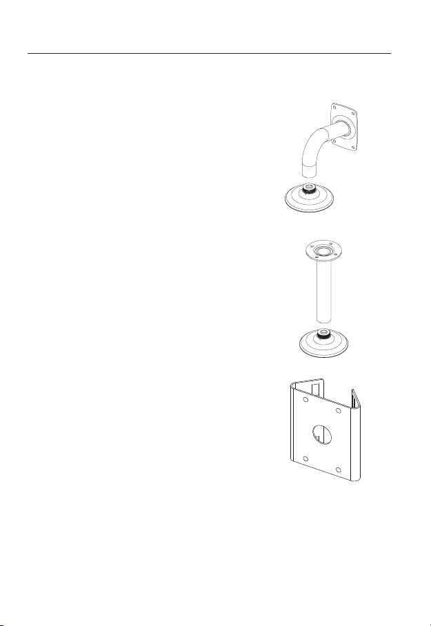
Optional Accessories for Installation
For your easier installation, you can purchase appropriate optional accessories available.
WALL MOUNT ADAPTOR(SCX-300WM)/
1.
HANGING MOUNT(SCX-300HM)
This adaptor is used when installing the dome
camera onto a wall.
CEILING MOUNT ADAPTOR(SCX-300CM)/
2.
HANGING MOUNT(SCX-300HM)
This adaptor is used when installing the dome
camera on a concrete ceiling.
POLE MOUNT ADAPTOR(SCX-300PM)
3.
This is an adaptor for WALL MOUNT ADAPTOR
(SCX-300WM) installation on a pole whose
diameter is bigger than 80mm.
30_ installation & connection
Page 31

CORNER MOUNT ADAPTOR (SCX-300KM)
4.
This is an adaptor for WALL MOUNT
ADAPTOR (SCX-300WM) installation on the
corner of wall joint.
Installing on the ceiling directly
Using the L-wrench provided, loosen 3 screws
1.
by turning them counterclockwise and separate
the dome cover.
Loosen 3 screws by turning them counterclock-
2.
wise, press both left and right lock releases inwards (in arrow direction) to unlock the stopper,
and then separate the camera from the case.
● INSTALLATION & CONNECTION
English _31
Page 32

installation & connection
Drill holes (diameter 5mm, more than 35mm
3.
deep) on the ceiling by matching to the holes
on the case bed, and insert plastic anchors
(HUD 5) fully into the holes. Fix the case bed
on the ceiling by using Tapping Screws (TH
M4xL30). (4 places)
Connect power and video cables and arrange cable running not to damage or
4.
squeeze them, and assemble the camera unit in the reverse way.
Adjust the lens aiming to your desired direction.
5.
Assemble the Dome Cover.
6.
For waterproof purpose, fix and secure the bolt using L-wrench provided.
For improved EMC performance, it is recommended
to use the insulation cap provided as an accessory.
For the wall mounting installation and how to connect the alarm cables, refer to the installation
M
instructions of SND-5080F. (pages 27~28)
32_ installation & connection
Page 33

Adjusting the monitoring direction for the camera (SND-5080/
SND-5080F/SNV-5080)
Panning
0˚
Tilting
Lens rotation
❖
Adjusting the monitoring direction
You can adjust the camera direction only when the camera is fixed on the ceiling.
Then, turning the camera to the left or right is referred to as “Panning”, while tilting the
angle is “Tilting”. For panning, the panning limit is 220° for the clockwise, and 135° for the
counterclockwise, a total of 355° enabled; further rotation is stopped by the stopper.
Adjust the panning angle so that the camera settles in the right horizontal position.
You can adjust the panning up to 135° in each one direction, and 220° in the other
direction, a total of 355°.
Adjust the tilting angle so that the camera settles in the right vertical position. You can
adjust the tilting between 0° and 90°.
The total rotation range is 355°. You can make adjustment in one direction up to
125°, and 230° in the other direction.
❖
Methods of adjustment
The case of wall installation
①
After mounting the camera on the wall, adjust the panning angle so that the camera
faces a desired direction when tilting.
②
Adjust the Rotate position to fit the video to the screen borders.
③
Then, adjust the tilting angle so that the camera faces the monitoring direction.
The case of ceiling installation
①
After mounting the camera on the ceiling, adjust the panning angle according to
the monitoring direction. You should adjust the panning angle lest that the video be
displayed upside down on the monitor.
②
Adjust the Rotate position to fit the video to the screen borders.
③
Then, adjust the tilting angle so that the camera faces the monitoring direction.
For smoother Rotate adjustment, set the Tilt position between 60° ~ 80°.
J
60˚ ~ 80˚
English _33
● INSTALLATION & CONNECTION
Page 34

installation & connection
www.samsungcctv.com
SNB-5000
www.samsungcctv.com
SNB-5000
www.samsungcctv.com
SNB-5000
www.samsungcctv.com
SNB-5000
www.samsungcctv.com
SNB-5000
www.samsungcctv.com
SNB-5000
MOUNTING THE LENS
Disconnect the power before proceeding.
The C lens and CS lens are not included in the product package.
M
It is recommended that megapixel lens are use on this camera to optimise performance.
Mounting the CS lens
Turn the optional CS lens clockwise to insert it.
Mounting the C lens
Turn the C mount adaptor clockwise to insert it and do the same with the C lens.
CS Lens
34_ installation & connection
C Lens
Page 35

Connecting the Auto Iris Lens connector
www.samsungcctv.com
SNB-5000
www.samsungcctv.com
SNB-5000
www.samsungcctv.com
SNB-5000
Insert the lens connector into the corresponding hole of the camera.
Focusing
Turn the lens left or right to control the zoom and focus the lens so that you can view a clear,
sharp object.
INSERTING/REMOVING AN SD MEMORY CARD
Inserting an SD Memory Card
Push the SD memory card in the direction of the arrow shown in the diagram.
● INSTALLATION & CONNECTION
English _35
Page 36

installation & connection
www.samsungcctv.com
SNB-5000
Do not insert the SD memory card while it’s upside down by force. Otherwise, it may damage the
J
SD memory card.
Removing an SD Memory Card
Gently press down on the exposed end of the memory card as shown in the diagram to
eject the memory card from the slot.
36_ installation & connection
Page 37

Pressing too hard on the SD memory card can cause the card to shoot out uncontrollably from the
J
slot when released.
To remove the SD memory card, set <Record> to <Off> from <SD Record> and press [Apply].
(page 83)
If you have saved data in the SD memory card, removing the SD memory card prior to setting
<Record> to OFF will cause damage to the data stored in the card.
If the SD memory is inserted, the SD LED indicator on the rear of the camera will turn on.
If there occurs a problem in the SD memory, the SD LED indicator will blink.
● INSTALLATION & CONNECTION
English _37
Page 38

installation & connection
MEMORY CARD INFORMATION (NOT INCLUDED)
What is a memory card?
The memory card is an external data storage device that has been developed to offer an
entirely new way to record and share video, audio, and text data using digital devices.
Selecting a memory card that’s suitable for you
Your camera supports SDHC memory cards.
You may, however, experience compatibility issues depending on the model and make of
the memory card.
For your camera, we recommend you use a memory card from the following
manufacturers:
SDHC/SD Memory Card : Sandisk, Transcend, Kingston
Your camera supports 2GB to 32GB of memory card capacity.
Playback performance can be affected depending on the speed of memory card, so use
the high-speed memory card.
To ensure proper recording of video data, we recommend you use a memory card that
supports at least read/write speed 10Mbps and Class 6.
Memory Card Use
SD and SDHC memory cards feature a switch that disables writing data on to the media.
Having this switch to the Lock position will prevent accidental deletion of data stored in the
memory card but at the same time will also prevent you from writing data on to the media.
❖
Memory Card Components
Contacts
Lock Switch
SD/SDHC
38_ installation & connection
Page 39

CONNECTING WITH OTHER DEVICE
SD CARD
AUDIO OUT
VIDEO
1 2 3 4 5
SD SYSTEM POWER
RESET
NETWORK
ACT
LINK
GND
1 : ALARM IN 4 :
2 : ALARM OUT 5 : GND
3 : ALARM COM
AC 24V
DC 12V
AUDIO IN
Ethernet
● INSTALLATION & CONNECTION
Monitor
Power
Monitor Out
Power
Monitor
Ethernet
English _39
Page 40

installation & connection
Connecting to the monitor
Connect the video out port of the camera to the video input port of the monitor.
In the initial installation of the camera, you can connect the camera to the monitor for checking
M
the connection status.
You must set <Video Output> to <ON> before the display screen can be activated. (page 76)
Connect the monitor test cable to the output port of the monitor.
Ethernet Connection
Connect the Ethernet cable to the local network or to the Internet.
Power Supply
Use the screwdriver to connect each line (+, –) of the power cable to the corresponding
power port of the camera.
Be careful not to reverse the polarity when you connect the power cable.
J
You can also use a router featuring PoE (Power over Ethernet) to supply power to the camera.
If using PoE, the heater will not operate at all.
Use an adaptor if the installation site requires heater operations. Adaptor is sold separately.
For the power specifications, refer to the “Appendix”. (page 92)
The instructions above are also applied to SND-5080/SND-5080F/SNV-5080.
M
40_ installation & connection
Page 41

Connecting to Audio Input/Output
www.samsungcctv.com
SNB-5000
Microphone
● INSTALLATION & CONNECTION
PC
Network
Microphone
Speaker Amp
Amp
Amp
Microphone
Speaker
Amp
Microphone
English _41
Page 42

installation & connection
1
ALARM IN
ALARM OUT
ALARM COM
GND
2
3
4
5
Connect the AUDIO IN port of the camera with the microphone directly or LINE OUT
1.
port of the amplifier that the microphone is connected to.
2.
Connect the AUDIO OUT port of the camera with the LINE IN port of the speaker.
Check the specifications for audio input.
3.
Audio Codec
G.711 PCM. μ-law 64kbps 8kHz sampling
Full duplex Audio
Audio in
Used for mono signal line input (Max.2.4 Vpp)
Audio out
Used for mono signal line output (Max.2.4 Vpp)
Line out impedance
600Ω
Alarm I/O Wiring Diagram
(5mA sink)
(30VDC 2A,
125VAC 0.5A MAX)
42_ installation & connection
Page 43

Connecting to the I/O port box
SD CARD
AUDIO OUT
VIDEO
1 2 3 4 5
SD SYSTEM POWER
RESET
NETWORK
ACT
LINK
GND
1 : ALARM IN 4 :
2 : ALARM OUT 5 : GND
3 : ALARM COM
AC 24V
DC 12V
AUDIO IN
1 2 3 4 5
1 : ALARM IN 4 :
2 : ALARM OUT 5 : GND
3 : ALARM COM
1 : ALARM IN 4 :
2 : ALARM OUT 5 : GND
3 : ALARM COM
Connect the Alarm I/O signal to the corresponding port of the rear port box.
<SNB-5000>
● INSTALLATION & CONNECTION
ALARM IN : Used to connect the alarm input signal.
ALARM OUT : Used to connect the alarm output signal.
ALARM COM : Common port where the alarm output signal is connected.
GND : Used for earth-grounding.
<SND-5080/SND-5080F/SNV-5080>
English _43
Page 44

network connection and setup
www.samsungcctv.com
SNB-5000
www.samsungcctv.com
SNB-5000
You can set up the network settings according to your network configurations.
CONNECTING THE CAMERA DIRECTLY TO LOCAL AREA
NETWORKING
Connecting to the camera from a local PC in the LAN
Launch an Internet browser on the local PC.
1.
Enter the IP address of the camera in the address bar of the browser.
2.
Camera
INTERNET
Camera
Firewall
External Remote PC
Local PC
<Local Network>
A remote PC in an external Internet out of the LAN network may not be able to connect to the
M
camera installed in the intranet if the port-forwarding is not properly set or a firewall is set.
In this case, to resolve the problem, contact your network administrator.
The IP address is set to 192.168.1.100 when shipped by default.
To change the IP address, use the IP Installer.
For further details on IP Installer use, refer to “Static IP Setup”. (Page 49)
44_ network connection and setup
DDNS Server
(Data Center, KOREA)
Page 45

CONNECTING THE CAMERA DIRECTLY TO A DHCP
www.samsungcctv.com
SNB-5000
BASED DSL/CABLE MODEM
DSL/Cable
Camera
Use the cross LAN cable to connect the network cable directly to your PC.
1.
Run the IP Installer and change the IP address of the camera so that you can use
2.
Modem
INTERNET
DDNS Server
(Data Center, KOREA)
External Remote PC
the web browser on your desktop to connect to the Internet.
Use the Internet browser to connect to the camera.
3.
Move to [Setup] page.
4.
Move to [Network] – [DDNS] and configure the DDNS settings.
5.
Move to [Network] – [Interface], and set the network type to [DHCP].
6.
Connect the camera, which was removed from your PC, directly to the modem.
7.
Restart the camera.
8.
For registering the DDNS settings, refer to “Registering with DDNS”. (page 80)
M
For configuring the DDNS settings, refer to “DDNS”. (page 78)
For setting the network type, refer to “Interface”. (page 77)
●
NETWORK CONNECTION AND SETUP
English _45
Page 46

network connection and setup
www.samsungcctv.com
SNB-5000
CONNECTING THE CAMERA DIRECTLY TO A PPPOE
MODEM
Camera
Use the cross LAN cable to connect the network cable directly to your PC.
1.
Run the IP Installer and change the IP address of the camera so that you can use
2.
the web browser on your desktop to connect to the Internet.
Use the Internet browser to connect to the camera.
3.
Move to [Setup] page.
4.
Move to [Network] – [DDNS] and configure the DDNS settings.
5.
Move to [Network] – [Interface], and set the network type to [PPPoE].
6.
Connect the camera, which was removed from your PC, directly to the modem.
7.
Restart the camera.
8.
For registering the DDNS settings, refer to “Registering with DDNS”. (page 80)
M
For configuring the DDNS settings, refer to “DDNS”. (page 78)
For setting the network type, refer to “Interface”. (page 77)
PPPoE Modem
INTERNET
DDNS Server
(Data Center, KOREA)
External Remote PC
46_ network connection and setup
Page 47

CONNECTING THE CAMERA TO AN IP ROUTER WITH THE
www.samsungcctv.com
SNB-5000
www.samsungcctv.com
SNB-5000
PPPOE/CABLE MODEM
This is for a small network environment such as homes, SOHO and ordinary shops.
Camera
PPPoE or
IP Router
Camera
Local PC
Cable Modem
Configuring the network settings of the local PC connected to an
IP router
Configuring the network settings of the local PC connected to an IP router, follow the
instructions below.
Select : <Network Neighborhood> <Properties> <Local Area Connection>
<Properties> <General> <Internet Protocol (TCP/IP)> <Properties>
<Obtain an IP address automatically> or <Use the following IP address>.
Follow the instructions below if you select <Use the following IP address>:
ex1) If the address (LAN IP) of the IP router is 192.168.1.1
IP address : 192.168.1.100
Subnet Mask : 255.255.255.0
Default Gateway : 192.168.1.1
ex2) If the address (LAN IP) of the IP router is 192.168.0.1
IP address : 192.168.0.100
Subnet Mask : 255.255.255.0
Default Gateway : 192.168.0.1
ex3) If the address (LAN IP) of the IP router is 192.168.xxx.1
IP address : 192.168.xxx.100
Subnet Mask : 255.255.255.0
Default Gateway : 192.168.xxx.1
For the address of the IP router, refer to the product’s documentation.
M
Refer to the “Port Range Forward (Port Mapping) Setup” section of the IP Router’s
documentation. (Page 53)
INTERNET
DDNS Server
(Data Center, KOREA)
PPPoE or
Cable Modem
External Remote
PC
English _47
●
NETWORK CONNECTION AND SETUP
Page 48

network connection and setup
BUTTONS USED IN IP INSTALLER
Item Description
Device Name
a
Mode
b
MAC(Ethernet)
c
Address
IP Address
d
Protocol
e
UPnP Status This function is not currently implemented.
f
Model name of the connected camera.
Click the column to sort the list by model name.
However, search will be stopped if clicked during the search.
Displays either <Static> or <Dynamic> for the current network connection
status.
Ethernet address for the connected camera.
Click the column to sort the list by Ethernet address.
However, search will be stopped if clicked during the search.
IP address.
Click the column to sort the list by IP address.
However, search will be stopped if clicked during the search.
The factory default is “192.168.1.100”.
Network setting for the camera.
The factory default is “IPv4”.
Cameras with the IPv6 setting will be displayed “IPv6”.
48_ network connection and setup
Page 49

URL
g
IPv4 Scans for cameras with the IPv4 setting.
h
IPv6 Scans for cameras with the IPv6 setting.
i
Search
j
Auto Set The IP Installer automatically configures the network settings.
k
Manual Set You should configure the network settings manually.
l
Exit Exits the IP Installer program.
m
Use IP Installer version 1.40 or higher.
M
DDNS URL address enabling access from the external Internet.
However, this will be replaced with the <IP Address> of the camera if
DDNS registration has failed.
Scans for cameras that are currently connected to the network.
However, this button will be grayed out if neither IPv4 nor IPv6 is checked.
STATIC IP SETUP
Manual Network Setup
Run <IP Installer_v 1.40.exe> to display the camera search list.
At the initial startup, both [Auto Set] and [Manual Set] will be grayed out.
For cameras found with the IPv6 setting, these buttons will be grayed out as the cameras do not
M
support this function.
Select a camera in the search list.
1.
Find the MAC (Ethernet) address
labeled on the rear of the camera.
Both the [Auto Set] and [Manual Set]
buttons will be activated.
Click [Manual Set].
2.
The Manual Setting dialog appears.
The default values of <IP Address>,
<Subnet Mask>, <Gateway>, <HTTP Port> and <VNP Port> of the camera will
be displayed.
The default <Password> is “4321”.
●
NETWORK CONNECTION AND SETUP
English _49
Page 50

network connection and setup
In the <Address> pane, provide the
3.
necessary information.
MAC (Ethernet) Address : The MAC
(Ethernet) address of the applicable
camera will be set automatically so you
don't need to input it manually.
If using an IP router
IP Address : Enter an address falling in
the IP range provided by the IP router.
ex) 192.168.1.2~254,
192.168.0.2~254,
192.168.XXX.2~254
Subnet Mask : The <Subnet Mask> of
the IP router will be the <Subnet Mask>
of the camera.
Gateway : The <Local IP Address> of
the IP router will be the <Gateway> of the camera.
The settings may differ depending on the connected IP router model.
M
For more information, refer to the user manual of the applicable router.
Refer to the “Port Range Forward (Port Mapping) Setup” section of the IP Router’s
documentation. (Page 53)
If not using an IP router
For setting <IP Address>, <Subnet Mask>, and <Gateway>, contact your network
administrator.
In the <Port> pane, provide
4.
necessary information.
HTTP Port : Used to access the
camera using the Internet browser,
defaulted to 80. Use the spin button
to change the HTTP Port value.
VNP Port : Used to control the video
signal transfer, defaulted to 4520.
Enter the password.
5.
This is the login password for the “admin” user who accesses the camera.
The default password is “4321”.
50_ network connection and setup
Page 51

6.
Click [OK].
Manual network setup will be completed.
When the manual setup including IP is completed, the camera will restart.
7.
If the IP router has more than one camera connected
Configure the IP related settings and the Port related settings distinctly with each other.
Category Camera #1 Camera #2
●
NETWORK CONNECTION AND SETUP
IP related settings
Port related settings
If the <HTTP Port> is set other than 80, you must provide the <Port> number in the address
M
bar of the Internet browser before you can access the camera.
ex) http://IP address : HTTP Port
IP Address
Subnet Mask
Gateway
HTTP Port
VNP Port
http://192.168.1.100:8080
192.168.1.100
255.255.255.0
192.168.1.1
8080
4520
Auto Network Setup
Run <IP Installer_v1.40.exe> to display the camera search list.
At the initial startup, both [Auto Set] and [Manual Set] will be grayed out.
For cameras found with the IPv6 setting, these buttons will be grayed out as the cameras do not
M
support this function.
Select a camera in the search list.
1.
Find the MAC (Ethernet) address labeled
on the rear of the camera.
Both the [Auto Set] and [Manual Set]
buttons will be activated.
Click [Auto Set].
2.
The Auto Setting dialog appears.
The <IP Address>, <Subnet Mask>,
and <Gateway> will be set automatically.
192.168.1.101
255.255.255.0
192.168.1.1
8081
4521
English _51
Page 52

network connection and setup
Enter the password.
3.
This is the login password for the
“admin” user who accesses the
camera. The default password is
“4321”.
Click [OK].
4.
Auto network setup will be completed.
The camera will automatically complete
5.
the network setting and restart.
DYNAMIC IP SETUP
Dynamic IP Environment Setup
Example of the Dynamic IP environment
If an IP router, with cameras connected, is assigned an IP address by the DHCP
server
If connecting the camera directly to modem using the DHCP protocols
If IPs are assigned by the internal DHCP server via the LAN
-
Checking the Dynamic IP
Run the IP Installer on the user’s local
1.
machine to display cameras allocated
with <Dynamic IP> addresses in the
list.
Select a camera in the list, and click
2.
[Manual Set] to check the <Dynamic
IP> of the camera.
If you uncheck <DHCP>, you can
change IP or <Port> to <Static>.
52_ network connection and setup
Page 53

PORT RANGE FORWARD (PORT MAPPING) SETUP
If you have installed an IP router with a camera connected, you must set the port range
forwarding on the IP router so that a remote PC can access the camera in it.
Manual Port Range Forwarding
From the Setup menu of the IP router,
1.
select <Applications & Gaming> <Port Range Forward>.
For setting the port range forward for
a third-party IP router, refer to the user
guide of that IP router.
Select <TCP> and <UDP Port> for
2.
each connected camera to the IP
router.
Each port number for the IP router
should match that specified in
<Network> - <Port> from the
camera's Setup menu.
When done, click [Save Settings].
3.
Your settings will be saved.
Above sample instructions are based on the CISCO’s IP Router (Model: LINKSYS).
M
The settings may differ depending on the connected IP router model.
For more information, refer to the user manual of the applicable router.
●
NETWORK CONNECTION AND SETUP
English _53
Page 54

network connection and setup
Setting up Port Range Forward for several network cameras
When several network camera connect to one IP router device, you should forward the
TCP 943 port of the router to the TCP 943 port of a connected camera.
If you don't set properly the TCP 943 port of the router, you cannot get any video stream from
J
the web page of the camera.
TCP 943 port is a port for the Silverlight policy server of a camera.
When Camera1 and Camera2 are connected to a router :
User Internet
Start End Protocol IP Address
943 943 TCP 192.168.1.100
3000 3000 TCP/UDP 192.168.1.100
3001 3001 TCP/UDP 192.168.1.101
4520 4520 TCP/UDP 192.168.1.100
4251 4521 TCP/UDP 192.168.1.101
8000 8000 TCP/UDP 192.168.1.100
8001 8081 TCP/UDP 192.168.1.101
You can set a rule of Port Forwarding on the IP router device through its configuration web page.
You cannot change the Sliverlight policy server port of a camera. This value is fixed
internally.
You can change the ports of the camera except the policy server port through its
configuration web pages.
54_ network connection and setup
IP router
Camera1 (192.168.1.100)
Web Server Port 8080
VNP Port 4250
RTSP Port 3000
Policy Server Port 943
Camera2 (192.168.1.101)
Web Server Port 8081
VNP Port 4251
RTSP Port 3001
Policy Server Port 943
Page 55

CONNECTING TO THE CAMERA FROM A SHARED LOCAL PC
Run the IP Installer.
1.
It will scan for connected cameras and
display a list of them.
Double-click a camera to access.
2.
The Internet browser starts and connects
to the camera.
Access to the camera can also be gained by typing the camera's IP address in the address bar of
M
the Internet browser.
CONNECTING TO THE CAMERA FROM A REMOTE PC VIA
THE INTERNET
Since using the IP Installer on a remote computer that is not in the IP Router’s network cluster
is not allowed, users can access cameras within an IP Router’s network by using the camera’s
DDNS URL.
Before you can access a camera in the IP router network, you should have set the
1.
port range forward for the IP router.
From the remote PC, launch the Internet browser and type the DDNS URL address
2.
of the camera, or the IP address of the IP router in the address bar.
ex) http://www.samsungipolis.com/[Product ID]
●
NETWORK CONNECTION AND SETUP
English _55
Page 56

web viewer
CONNECTING TO THE CAMERA
Normally, you would
Launch the Internet browser.
1.
Type the IP address of the camera in
2.
the address bar.
ex) • IP address (IPv4) : 192.168.1.100
http://192.168.1.100
- the Login dialog should appear.
IP address (IPv6) : 2001:230:abcd:
•
ffff:0000:0000:ffff:1111
http://[2001:230:abcd:ffff:0000
:0000:ffff:1111]
If the HTTP port is other than 80
Launch the Internet browser.
1.
Type the IP address and HTTP port number of the camera in the address bar.
2.
ex) IP address : 192.168.1.100:HTTP Port number(8080)
http://192.168.1.100:8080 - the Login dialog should appear.
Using URL
Launch the Internet browser.
1.
Type the DDNS URL of the camera in the address bar.
2.
ex) URL address : http://www.samsungipolis.com/[Product ID]
- the Login dialog should appear.
56_ web viewer
Page 57

To check the DDNS address
If the camera is connected directly to the DHCP cable modem, DSL modem, or PPPoE
modem, the IP address of your network will be changed each time you try to connect to
the ISP (Internet Service Provider) server.
If this is the case, you will not be informed of the IP address changed by DDNS.
Once you register a dynamic IP-based device with the DDNS server, you can easily check
the changed IP when you try to access the device.
To add the IP address to the <DDNS> server, visit www.samsungipolis.com and register
your device, and set the DDNS option to <Samsung DDNS> before providing the user ID
and password for the DDNS server.
LOGIN
The default user ID is “admin”, and the default password is “4321”.
Enter “admin” in the <User Name>
1.
input box.
Enter “4321” in the <Password> input
2.
box.
If the password is changed, enter the
changed password instead.
Click [OK].
3.
If you have logged in successfully, you
will the Live Viewer screen.
For security purposes, ensure that you change the password in <System> - <User>.
M
The administrator ID, “admin”, is fixed and can not be changed.
If you check the “Save this password in your password list” option when your input is done, in
future you will be logged in automatically without being prompted to enter the login information.
● WEB VIEWER
If you are using Internet Explorer 7.0 or 8.0 as the default web browser, you can view the best
J
quality image with a screen ratio of 100%. Reducing the ratio may cut the image on the borders.
English _57
Page 58

web viewer
This network camera uses Microsoft Silverlight for displaying the video.
INSTALLING SILVERLIGHT RUNTIME
If your PC has not installed Silverlight Runtime or has just installed an old runtime version, you will
be redirected to the Silverlight Runtime installation page automatically when accessing the web
viewer.
Click <Click Here>.
1.
When the file download dialog pops up,
2.
click <Run>.
When the download is completed, click
3.
<Run>.
The Silverlight Runtime installation page
4.
will be displayed. <Install now> to
proceed with the installation.
58_ web viewer
Page 59

When done, click <Close>.
5.
Close and restart the web browser, and
6.
try to access the Web Viewer.
When Siverlight Runtime is properly
installed, you will see the Live screen.
For normal installation, set the Block
J
Popup setting as follows:
Internet Explorer Tools Block
Popup Always allow popups from
the current site(A)
However, MAC OS X users who are not connected to the Internet can use the provided installation
DVD to install Silverlight Runtime (Run the executable “Silverlight_xxx.dmg” in the DVD. You will
be guided through installation of the software).
● WEB VIEWER
English _59
Page 60

web viewer
USING THE LIVE SCREEN
Item Description
Monitoring Move to the monitoring screen.
a
Playback Switch to the monitoring screen that plays recording data in the SD memory.
b
Setup Move to the Setup screen.
c
Viewer Screen Displays the Live video on the screen.
d
Alarm Output Activate the Alarm Out port.
e
Audio Display the audio Listen and Talk toggle button on the screen.
f
Reset Alarm Reset the alarm output settings.
g
Camera Menu
h
Digital PTZ You can use the mouse wheel to activate the digital zooming.
i
Screen
Optimization,
j
Full Screen
Capture Saves the snapshot as an image file in the .jpeg or .bmp format.
k
Used to retrieve and customize the Camera Setup menu.
For selecting and saving each menu item, refer to “Using the Camera Menu”.
(page 65)
Adjust the screen to the optimal size, and display the Full Screen icon on the Live
screen.
60_ web viewer
Page 61

You can select a profile type in <Video Profile> under the <Audio & Video> setup
menu.
For IE 6.0 users, press the Browse button next to the <Video Profile> dialog
l
Video Format
If the temperature drops below the operational range, video signal may not be produced. In such
M
cases, please wait for the video.
M
and select a profile type again if the selected profile is not played.
If the “Invalid codec” message is displayed, select a profile type from the profile
M
list again.
To capture the snapshot
Click [ ] on the scene to capture.
1.
The Capture dialog should appear.
Click [Save] button.
2.
The screenshot will be saved in the
specified path.
If you are using the IE8 as the default web
M
browser, select “Tools-Internet OptionsSecurity” and uncheck “Use protected
mode”.
To toggle the audio sound
Click the [Audio ( )] button.
1.
The corresponding button will be
displayed in the Viewer.
Click the button to listen to / mute the
2.
sound as you wish.
This button operates as a toggle button.
● WEB VIEWER
English _61
Page 62

web viewer
To toggle the microphone sound
Click the [Mic ( )] button.
1.
The corresponding button will be displayed in the Viewer.
“Cannot find audio recording device” message appears if there is no Microphone.
J
Click the button to start / stop talking.
2.
This button operates as a toggle button.
The Silverlight permission dialog appears when you click the microphone button.
To fit the full screen
Click the [Full Screen ( )] button.
1.
The corresponding button will be displayed in the Viewer.
Click the button.
2.
This will fit the Viewer to the full screen.
To exit the full screen mode, press [Esc] on the keyboard.
3.
PLAYBACK
Click the [Playback ( )] button.
1.
Specify the start time and end time of
2.
your search.
Select a search type.
3.
Click the [Search ( )] button.
4.
The search results will be displayed in
the list.
If more than 500 events are recorded
M
within the search period, your search will
be limited up to the date when the 500th event is recorded.
For instance, if the search period is between 10th and 15th day of the month, and more than 800
events were recorded 10th through 11th, your search will be limited up to 11th day with a total of
800 events, and events after then (from 12th) will not be found.
62_ web viewer
Page 63

Select a data item to play in the search
5.
list.
Click the [Play ( )] button.
6.
To stop playing the video, click [Stop
7.
( )].
To return to the search screen, click
[Exit ( )].
To check time information of the playing video
Click the [About ( )] button.
1.
Date and time information appears on the screen.
2.
To back up the searched video
Click [ ] on the scene to back up.
1.
Save as window appears.
Click [Save].
2.
The screenshot will be backed up to the
specified path.
If you are using the IE8 as the default web
M
browser, select “Tools-Internet OptionsSecurity” and uncheck “Use protected
mode”.
● WEB VIEWER
English _63
Page 64

web viewer
PLAYING THE BACKUP RECORDINGS
You can play backup recordings by using the SlimPlayer.
To download SlimPlayer
Click [SlimPlayer ( )].
1.
You will see a download dialog where
you can specify the download path.
Specify the path with a proper file name
2.
and click [Save].
Unzip the downloaded file and run the
3.
executable.
64_ web viewer
Page 65

camera setup
USING THE CAMERA MENU
Follow the steps below if you run the Web Viewer for setting the menus.
Launch the Web Viewer.
1.
Click [Camera Menu ( )] in the left
2.
corner of the Live screen.
The camera setup menu appears.
Use the Up/Down (▲/▼) buttons to move
3.
to a desired item.
To change the value of a selected item,
4.
use the Left/Right (◄/►) buttons.
To break down to a sub-menu structure,
click [Enter ( )] on the selected item.
: This arrow appears next to a menu that contains sub items.
If <IV analysis function> is enabled, camera’s OSD menu operation can be set as an event.
J
CAMERA MENU SETUP
You can change the camera settings according to the environment where the camera is located.
SSDR (Samsung Super Dynamic Range) Setup
In a scene where the difference between bright and dark is severe, you can increase the
brightness of the dark area alone to regulate the overall brightness.
▲/▼ ◄/► ENTER ▲/▼ ◄/► ENTER
Move to <SSDR> and select <ON>.
1.
MAI N SET UP
S SDR ON
WHIT E B AL ATW
BACK LIG HT OFF
EXPO SUR E
SPEC IAL
EXIT
● CAMERA SETUP
English _65
Page 66

camera setup
Configure the <SSDR> and <D-RANGE>
2.
settings as necessary.
SSDR : Adjust the level of the dynamic
range.
D-RANGE : Select the amplitude area of
D-RA NGE NAR RO W
RETU RN
the dynamic range.
3.
When completed, select <RETURN> to
return to the previous screen.
White Balance Setup
You can correct the image colors based on white under any lighting conditions.
▲/▼
◄/► ENTER ▲/▼ ◄/► ENTER
1.
Move to <WHITE BAL> and select a
setting value.
ATW : Corrects the colors of the camera
video automatically.
MANUAL : You can adjust the red and
blue gains of the camera video manually.
AWC SET : Corrects the colors of the
camera video to be optimized to the
current lighting condition and screen
mode.
You may need readjustment if the lighting condition is changed.
Put the focus of the camera to a white paper and press the [Enter ( )] button.
OUTDOOR : Automatically corrects the video colors of the camera to be
optimized to the outdoor environment.
INDOOR : Automatically corrects the video colors of the camera to be optimized
to the indoor environment.
2.
To adjust it manually, select <MANUAL>.
Specify the <RED> and <BLUE> values
3.
as necessary.
4.
When completed, select <RETURN> to
return to the previous screen.
SSDR ON
BACK LIG HT OFF
EXPO SUR E
SPEC IAL
EXIT
BLUE
RETU RN
SSD R SET UP
S SDR
MAI N SET UP
W HIT E BAL AT W
WHI TE BA L MAN UAL S ETU P
R ED
8
5 29
5 32
66_ camera setup
Page 67

Custom Backlight Setup
You can specify a desired area on the video manually and set the area to be displayed
more clearly.
▲/▼ ◄/► ENTER ▲/▼/◄/► ENTER
Move to <BACKLIGHT>.
1.
Select <BLC>.
2.
Set the BLC <LEVEL>.
3.
You can change the level to adjust the
brightness of the monitoring area.
Set the <TOP, BOTTOM, LEFT, RIGHT>
4.
levels to specify the target area.
When completed, select <RETURN> to
5.
return to the previous screen.
MAI N SET UP
SSDR ON
WHIT E B AL ATW
B ACK LIGHT BLC
EXPO SUR E
SPEC IAL
EXIT
BLC S ETU P
L EVE L LOW
TOP
BOTT OM
LEFT
RIGH T
RETU RN
3 0
7 5
3 0
7 0
● CAMERA SETUP
English _67
Page 68

camera setup
HLC (Highlight Compensation) Setup
When a strong light such as streetlamp or headlight faces forward to the camera, you can
mask that exposed area in order to protect it from being saturated.
▲/▼ ◄/► ENTER ▲/▼ ◄/► ENTER
Select <BACKLIGHT>.
1.
Select <HLC>.
2.
Set the <LEVEL> and the <MASK TONE>.
3.
LEVEL : Adjust the brightness level so
as to remove the incoming highlight
from a specific condition.
MASK TONE : Adjust the mask tone of
the highlighted area.
When completed, select <RETURN> to
4.
return to the previous screen.
This function will only be activated at night.
M
At night, HLC will not function if the scene is either too bright or too dark.
SSDR ON
WHIT E B AL ATW
EXPO SUR E
SPEC IAL
EXIT
MASK TO NE
RETU RN
MAI N SET UP
B ACK LIGHT HLC
HLC S ETU P
L EVE L MID DL E
7
68_ camera setup
Page 69

Exposure Setup
You can adjust the exposure level of the camera.
▲/▼ ENTER ▲/▼/◄/► ENTER ▲/▼/◄/► ENTER
Move to <EXPOSURE> and select a
1.
setting value.
SSDR ON
WHIT E B AL ATW
BACK LIG HT OFF
E XPO SURE
SPEC IAL
EXIT
Select each item and set it appropriately.
2.
BRIGHTNESS : Adjust the screen
brightness.
IRIS : If set to <MANUAL>, you can
adjust the iris of the camera manually.
SHUTTER : Adjust the electronic shutter
of the camera.
MANUAL : Adjust the shutter speed of
-
EXP OS URE S ETU P
B RIG HT NES S
IRIS AUT O
SHUT TER
AGC HIG H
SSNR 3 ON
SENS -UP AU TO
RETU RN
the camera manually.
A.FLK : This will prevent the screen from flickering.
-
AGC : Specify how to adjust the level according to the luminance.
MANUAL : Adjust the screen brightness manually.
-
SSNR3 : Adjust the noise reduction level.
SSN R3 LE VE L S ETUP
L EVE L
RETU RN
MAI N SET UP
● CAMERA SETUP
5 0
---
1 2
English _69
Page 70

camera setup
SENS-UP : Automatically senses the
darkness level at night or in a low contrast
scene and extends the accumulation time
accordingly for a bright and sharp image.
If you set the shutter mode to MANUAL/
FLICKERLESS, SENS-UP mode will be
deactivated.
The greater the video accumulation factor is,
the brighter the screen is but the afterimage
of a moving object grows accordingly.
LIMIT : Set the work condition to Auto mode in a low contrast scene.
-
When completed, select <RETURN> to return to the previous screen.
3.
Screen Display Setup
You can specify the camera title and the OSD color that will be displayed on the screen.
▲/▼ ◄/► ENTER ▲/▼ ◄/► ENTER
Select <SPECIAL>.
1.
SEN S- UP LI MIT SETU P
L IMI T 2 X
RETU RN
MAI N SET UP
SSDR ON
WHIT E B AL ATW
BACK LIG HT OFF
EXPO SUR E
S PEC IAL
EXIT
Select <CAM TITLE>.
2.
70_ camera setup
SPE CI AL SE TUP
C AM TI TLE OFF
OSD COL OR WH IT E
DAY/ NIG HT AUTO
IMAG E A DJ
RETU RN
Page 71

3.
Use alphanumeric characters in the list
and enter a desired title in the bottom
input line.
You can enter up to 15 characters for the title.
Select <POS> and specify where to
4.
display the camera title.
When the camera title is displayed, use the
direction buttons to specify the position;
CAM ER A T IT LE SETUP
A B C D E F G H I J K L M
N O P Q R S T U V W X Y
a b c d e f g h i j k l m
n o p q r s t u v w x y
_
. 0 1 2 3 4 5 6 7 8 9
CLR P OS END
__ __ __ __ _ __ __ __
Click OK to return to the previous menu.
When done, select <END>.
5.
To cancel your input, select <CLR>.
When completed, select <RETURN> to return to the previous screen.
6.
OSD Color Setup
You can set the OSD color on the screen to your preference.
▲/▼ ENTER ▲/▼ ◄/► ENTER
Select <SPECIAL>.
1.
Move to <OSD COLOR> and select a
2.
desired color.
When completed, select <RETURN> to
3.
return to the previous screen.
MAI N SET UP
SSDR ON
WHIT E B AL ATW
BACK LIG HT OFF
EXPO SUR E
S PEC IAL
EXIT
SPE CI AL SE TUP
CAM TIT LE OFF
O SD CO LOR W HI TE
DAY/ NIG HT AUTO
IMAG E A DJ
RETU RN
Z
z
● CAMERA SETUP
English _71
Page 72

camera setup
Day/Night Mode Setup
You can switch the mode to adjust the black and white level as well as the colors.
▲/▼ ◄/► ENTER ▲/▼ ◄/► ENTER
Select <SPECIAL>.
1.
SSDR ON
WHIT E B AL ATW
BACK LIG HT OFF
EXPO SUR E
EXIT
Select <DAY/NIGHT>, and specify a
2.
desired mode setting value.
AUTO : Displays in color mode during
normal daytime and switches to black
and white mode in a low contrast scene
at night.
Press the [Enter ( )] button to
CAM TIT LE OFF
OSD COL OR WH IT E
IMAG E A DJ
RETU RN
adjust the switching interval between
the two modes.
If you set the AGC mode to OFF from
<EXPOSURE>, the AUTO DAY/NIGHT mode will be disabled accordingly.
DWELL TIME : This is the time while
each applicable lighting condition is
kept in order to enable the switch
between day and night modes.
DURATION : Adjust the brightness of
-
DURA TIO N SLO W
RETU RN
the lighting where the mode switch
occurs.
COLOR : Always displays the video in
colors.
B/W : Always displays the video in black
and white.
When completed, select <RETURN> to return to the previous screen.
3.
MAI N SET UP
S PEC IAL
SPE CI AL SE TUP
D AY/ NI GHT AUTO
DAY /N IGH T AUT O SET UP
D WEL L TIM E 5 S EC
72_ camera setup
Page 73

Image Adjustment
You can configure the sharpness, gamma level, and color settings of an image to your
preference.
▲/▼ ◄/► ENTER ▲/▼ ◄/► ENTER
Select <SPECIAL>.
1.
Select <IMAGE ADJ>.
2.
Select each item and set it appropriately.
3.
If selecting <SHARPNESS>, you can
adjust the sharpness of the image.
SHARPNESS : Adjust the overall sharpness of the image.
The higher the level is, the sharper
and clearer the outline of the image
becomes.
GAMMA : Adjust the contrast of the
image.
COLOR LEVEL : Adjust the color level of the image.
When completed, select <RETURN> to return to the previous screen.
4.
MAI N SET UP
SSDR ON
WHIT E B AL ATW
BACK LIG HT OFF
EXPO SUR E
S PEC IAL
EXIT
SPE CI AL SE TUP
CAM TIT LE OFF
OSD COL OR WH IT E
DAY/ NIG HT AUTO
I MAG E ADJ
RETU RN
IMA GE SE TU P
S HAR PN ESS ON
GAMM A 0.4 5
COLO R L EVEL
RETU RN
5 0
● CAMERA SETUP
English _73
Page 74

setup screen
SETUP
You can configure the audio & video, network, event and system settings of the camera in the
network.
In the Live screen, click <Setup ( )>.
1.
The Setup screen appears.
2.
AUDIO & VIDEO SETUP
Video Profile
From the Setup menu, select the <Audio
1.
& Video (
Click <Video Profile>.
2.
Select a <Video Profile> number.
3.
Click the input box of each item and
4.
enter / select a desired value.
The context menu may differ depending on the
selected codec type.
Default Profile : This is the default
video profile.
Fixed Framerate Profile : Fix the
frame rate of the selected profile
regardless of the settings of other
profiles.
E-mail/FTP Profile : Video profile to be transferred to the specified email or FTP
site.
Record Profile : This is the profile that is applied to video recording.
When done, click [Apply].
5.
)> tab.
Only the MJPEG codec can be set as the E-mail/FTP Profile.
Profiles using H.264 codec can be stored in the SD memory only in resolutions of 640x480 or
M
less.
MPEG4 videos can not be stored in the SD memory.
74_ setup screen
Page 75

To add a video profile
You can add as many codecs as necessary so that a variety of profiles can be applied
according to the recording condition.
Select a profile number.
1.
Provide the name and select a codec.
2.
Specify the conditions under which the codec will be applied.
3.
Specify the details of the selected codec including resolution and frame rate.
4.
Resolution : Set the video size of the MPEG4, H.264, and MJPEG files.
Framerate : Specify the frame rate.
Compression : Specify the compression rate of the video.
Bitrate control : You can select one from constant bit rate and variable bit rate for
compression. Constant bit rate (CBR) varies the video quality and fixes network
transfer bit rate, while variable bit rate emphasizes the quality by varying network
transfer bit rate.
If you set the resolution to 1280X1024, the maximum frame rate is 22 fps.
Target bitrate : Specify the bit rate at which you will transfer the video.
Encoding priority : You can set the video transfer method to Framerate or
Compression.
GOP size : Select a GOP size between 1 and 15.
Profile : The H.264 profiling method is fixed to <High>.
Entropy coding : Reduce the possible compression loss due to encoding.
Multicast (VNP) : Specify the use of the VNP protocol.
-
IPv4 : Enter an IPv4 address with which you can connect to the IPv4 network.
-
Port : Specify the video communication port.
TTL : Set the TTL for the VNP packet.
-
Multicast (RTP) : Specify the use of the RTP protocol.
-
IPv4 : Enter an IPv4 address with which you can connect to the IPv4 network.
-
Port : Specify the video communication port.
-
TTL : You can set the TTL for the RTP packet.
● SETUP SCREEN
What is GOP size?
GOP (Group of Pictures) is a set of video frames for MPEG4 and H.264 format
compression, indicating a collection of frames from the initial I-Frame (key frame) to the
next I-Frame. GOP consists of 2 kinds of frames: I-Frame and P-Frame.
I-Frame is the basic frame for the compression, also known as Key Frame, which
contains one complete image data. P-Frame contains only the data that has changed
from the preceding I-Frame.
You can set between 1 and 15 for the MPEG4 and H.264 CODEC.
English _75
Page 76

setup screen
Video Setup
From the Setup menu, select the
1.
<Audio & Video
2.
Click <Video Setup>.
Select a <Video Source> mode.
3.
Flip Mode : Turn upside down the
image that is captured by the
camera.
Mirror Mode : Flip horizontal the
image that is captured by the
camera.
Click the input box of each item in
4.
<Privacy Area Configuration> and enter / select a desired value.
You can set up to 12 privacy zones.
5.
Set the <Video Output>.
If you select <OFF>, the video signal will not be output via the VIDEO OUT port.
-
6.
When done, click [Apply].
To set the privacy zone
You can specify a certain area of the camera video to be protected for your privacy.
1.
Set it to <Enable>.
2.
Place the cursor at a point in the video
and drag it to whatever you need.
3.
Specify the <Color> that will fill the
privacy area.
4.
To cancel your selection, simply click
[Clear].
When done, click [Apply].
5.
( )
> tab.
76_ setup screen
Page 77

Audio Setup
You can configure the I/O settings of the audio source from the camera.
From the Setup menu, select the
1.
<Audio & Video ( )> tab.
Click <Audio Setup>.
2.
Adjust the audio I/O levels to your
3.
preference.
Audio-In : Set the audio input value.
Audio-Out : Set the audio output
value.
When done, click [Apply].
4.
NETWORK SETUP
Interface
From the Setup menu, select the
1.
<Network ( )> tab.
Click <Interface>.
2.
Set the <Interface> and <IPv6 Setup>
3.
as necessary.
IP Type : Select an IP connection
type.
Manual : Specify the IP address,
Subnet Mask, Gateway, DNS1,
and DNS2.
DHCP : Specify the DNS1 and DNS2.
PPPoE : Specify the DNS1, DNS2, ID and password.
-
If you set it to <Manual>, you should specify the IP, Subnet Mask, Gateway, DNS 1 & 2 manually.
MAC Address : Shows the MAC address.
IP Address : Displays the current IP address.
Subnet Mask : Displays the <Subnet Mask> for the set IP.
Gateway : Displays the <Gateway> for the set IP.
● SETUP SCREEN
English _77
Page 78

setup screen
DNS1/DNS2 : Displays the DNS(Domain Name Service) server address.
IPv6 Use : Specify the use of IPv6.
IPv6 Address : Obtains the IPv6 address to access the IPv6 network.
4.
When done, click [Apply].
Port
1.
From the Setup menu, select the
<Network ( )> tab.
Select <Port>.
2.
3.
Type in each item in the Port menu as
necessary.
Neither the port range between 0 and 1023
nor port 3702 is available.
HTTP port : HTTP port used to
access the camera via the web
browser.
The default is 80(TCP).
VNP Port : Set a port used to transfer video signals with the Samsung protocols.
RTSP Port : Used to transfer videos in the RTSP mode; the default is 554.
VIEWER Port : Used to transfer videos to the Web Viewer; the default is 4520.
The port range of the Viewer is between 4502 and 4532. If the VNP port is with this effective
range, the Viewer port should be specified the same as the VNP port.
4.
When done, click [Apply].
DDNS
DDNS is an abbreviation of Dynamic Domain Name Service that converts the IP address of
a camera into a general Host Name so that the user can easily remember it.
1.
From the Setup menu, select the
<Network ( )> tab.
2.
Click <DDNS>.
Select <DDNS>.
3.
4.
Type in the DDNS items according to
the selected type.
Samsung DDNS : Select this if you
use the DDNS server provided by
Samsung Techwin.
78_ setup screen
Page 79

Public DDNS : Select one of provided public DDNS servers when you use a public
DDNS server.
Host name : Enter the name of the host (i.e., host name of Dyndns) that is registered
with the DDNS server.
User Name : Enter the user name for the DDNS service. (i.e., user ID that is
registered with Dyndns)
Password : Enter the password for the DDNS service. (i.e., password that is
registered with Dyndns)
When done, click [Apply].
5.
IP Filtering
You can create a list of IPs that you want to grant or deny access to them.
From the Setup menu, select the
1.
<Network ( )> tab.
Click <IP filtering>.
2.
Select a <Filtering Type>.
3.
Deny : If selecting this, access from
those IPs that are added to the
filtering will be restricted.
Allow : If selecting this, access from
only those IPs that are added to the
filtering will be accepted.
Provide the IP that you want to grant or
4.
deny access from.
When done, click [Apply].
5.
SSL
You can select a secure connection system or install the public certificate for this purpose.
From the Setup menu, select the
1.
<Network ( )> tab.
Click <SSL>.
2.
Select a secure connection system.
3.
To access the camera using HTTPS mode,
you have to type the IP address for the camera
in the form of “https://<Camera_IP>”.
● SETUP SCREEN
English _79
Page 80

setup screen
Search for the public certificate that you want to install on the camera.
4.
To install the certificate on the camera, you need to provide a certificate name (it can
be arbitrarily assigned by the user), certificate file issued from the certification authority and a key file.
The <HTTPS(Secure connection mode using the public certificate)> item will be active only if
there exists a public certificate installed.
When done, click [Apply].
5.
Installing the certificate
Enter the certificate name.
1.
Select the certificate file to be installed and certificate key, and click [Install ( )]
2.
button.
Deleting the certificate
Click [Delete ( )] button.
1.
Registering with DDNS
To register your product with the Samsung DDNS
Visit the iPOLiS web site(www.
1.
samsungipolis.com) and sign in with a
registered account.
From the top menu bar, select <DDNS
2.
SERVICE>-<MY DDNS>.
80_ setup screen
Page 81

3.
Click [PRODUCT REGISTRATION].
Enter the product domain.
4.
You must perform the duplicate check for the
domain that you entered.
Select a <CLASSIFICATION> and
5.
specify the <MODEL NUMBER>.
Specify the product location with a
6.
description if necessary.
Click [REGISTRATION].
7.
The product will be added to the product list that you can check.
To connect to the Samsung DDNS in camera setup
From the DDNS setup page, set
1.
<DDNS> to <Samsung DDNS>.
Provide the <User Name> and <Pass-
2.
word> that you registered with the
DDNS site.
Click [Apply].
3.
When the connection is successfully
made, you will see the message of
<(Success)> on the screen.
Configuring public DDNS in Camera Settings
Open the DDNS settings page and select <Public DDNS> for <DDNS>.
1.
Enter the corresponding site’s host name, user name and password.
2.
Click [Apply] button.
3.
If the connection properly establishes, <(Success)> appears.
Once completed with the configuration, click [Apply] button.
4.
● SETUP SCREEN
English _81
Page 82

setup screen
EVENT SETUP
FTP/E-mail
You can configure the FTP/E-mail server settings so that you can transfer the images
stored in the camera to your PC if an event occurs.
From the Setup menu, select the
1.
<Event ( )> tab.
Click <FTP / E-mail>.
2.
Select <FTP Configuration> or
3.
<E-mail Configuration> and enter /
select a desired value.
FTP Configuration
Server Address : Enter the IP ad-
dress of the FTP server that you
transfer the alarm images to.
User ID : Enter the user ID with
which you will log in to the FTP
server.
Password : Enter the user account password for logging into the FTP server.
Upload Directory : Specify the FTP path where you will transfer the alarm
images.
Port : The default port of the FTP server is 21; however, you can use a different
port number according to the FTP server settings.
Passive Mode : Select <On> if you need to connect in passive mode due to the
firewall or the FTP server settings.
E-mail Configuration
Server Address : Enter the IP address of the email server that you use for the
email transfer.
ex) SMTP. hotmail. com
Use Authentication : Select whether to use authorization.
User ID : Enter the user ID for logging into the email server.
Password : Enter the user account password for logging into the email server.
Port : The default port of the email server is 25; however, you can use a different
port number according to the email server settings.
Recipient : Enter the address of the email recipient.
Sender : Enter the address of the email sender. If the sender address is incor-
rect, the email from the sender may be classified as SPAM by the email server
and thus may not be sent.
82_ setup screen
Page 83

Subject : Enter a subject for your email.
Body : Provide the text for the massage. Attach the alarm images to the email
that you are preparing.
When done, click [Apply].
4.
SD Record
You can set the record conditions or the use of recording for the SD memory, check the
size of stored data, or format the SD memory itself.
From the Setup menu, select the
1.
<Event ( )> tab.
Click <SD Record>.
2.
To make recording on the SD memory
Check the <Total Size> and the <Free Size>.
1.
If the SD memory has a sufficient free space, set <Record> to <On>.
2.
Otherwise, check the stored data and if you find them not important, then click
<Format> to format the SD memory.
If your SD memory card writes slowly, only one frame per second will be stored.
For a SD memory card with a large capacity, the formatting will be slowed down accordingly.
Note that only one frame per second (1 fps) will be stored for the following resolutions : 1280x1024,
1280x720, 800x600.
If the size of data grows with time, only 1 fps can be stored even if you set the record quality to Full
Frame.
Specify the record conditions.
3.
Record 1 fps forcibly : Only one frame per second will be recorded regardless of
the existing record profile.
Overwrite : If the SD memory is full, this will delete old data and store new data in
replacement.
● SETUP SCREEN
English _83
Page 84

setup screen
Pre-alarm duration : Specify the time point before the occurrence of the alarm;
starting from the time point, the images will be transferred. You can specify up to
5 seconds before the occurrence of the alarm.
Post-alarm duration : Specify the time point after the occurrence of the alarm; to
the specified time point, the images will be transferred. You can specify up to 120
seconds after the occurrence of the alarm.
When done, click [Apply].
4.
Alarm Input
You can set the alarm input type, activation time, and operation mode.
From the Setup menu, select the
1.
<Event ( )> tab.
Click <Alarm input>.
2.
Specify an input device.
3.
Type
Normal Open : It is normally open,
but if it is closed, an alarm will be
triggered.
Normal Close : It is normally
closed, but if it is open, an alarm
will be
triggered.
Specify the <Activation time>.
4.
Always : Always check if an alarm occurs. It activates in operated mode when the
alarm occurs.
Only scheduled time : Check if an alarm occurs at a specified day of the week for
a specified time period. It activates in operated mode when the alarm occurs.
Specify an operation that will perform if an alarm occurs.
5.
Alarm output : Specify the alarm output time in the alarm input setup.
E-mail Sending : Specify the use of email transfer in the alarm input setup.
Record : Specify the use of recording in the alarm input setup.
When done, click [Apply].
6.
84_ setup screen
Page 85

Video analysis
From the Setup menu, select the
1.
<Event ( )> tab.
Click <Video analysis>.
2.
Specify the use of Intelligent Video
3.
Analysis.
Specify the use of overlay.
4.
If you set it to Enable, the event rules
will be shown on the screen.
Select a sensitivity level at which the
5.
camera detects the object.
Specify the object size.
6.
Select an event rule.
7.
You can select a total of 3 rules including the
virtual line and the specified area.
Specify the activation time and activation
8.
condition.
For more information about <Activation
time> and <Action>, refer to “Alarm Input”.
(page 84)
Specify whether or not the alarm area is displayed.
9.
- If you set it to <On>, the suspect area where the alarm occurs will be marked in a
red box.
To use the IV analysis function according to the virtual line based rule
Set <IV analysis function> to
1.
<Enable>.
Set the event rule to <Virtual line based
2.
rules>.
Click a desired area in the video and
3.
drag it to the end point, and right-click it.
Select a desired <Virtual Line Rules>.
4.
You can specify up to 3 event rules for the virtual line.
Right : A movement from left to right in the virtual line will be detected.
Left : A movement from right to left in the virtual line will be detected.
Both : A movement in any direction in the virtual line will be detected.
English _85
● SETUP SCREEN
Page 86

setup screen
Click [OK].
5.
To cancel the existing line, right-click on the line and select [Delete] in the context
menu.
When done, click [Apply].
6.
To use the IV analysis function according to the defined area based rule
Set <IV analysis function> to
1.
<Enable>.
Set the event rule to <Defined area
2.
based rules>.
Select the vertex of a desired area,
3.
and right-click it to display the context
menu.
Select a desired <Defined Area Rules>.
4.
You can specify up to 3 defined area event rules.
Entering : An event where a moving object passes through the defined area and
enters inside will be detected.
Exiting : An event where a moving object passes through the defined area and
exits outside will be detected.
Appearing/Disappearing : An event will be detected where an object that has not
existed in the area until the previous frame, suddenly appears or disappears in the
area without passing through the defined area.
Click [OK].
5.
To cancel the specified area, right-click on the area and select [Delete] in the context
menu.
When done, click [Apply].
6.
To use the IV analysis function according to the whole area based rule
Set <IV analysis function> to
1.
<Enable>.
Set the event rule to <Entire area
2.
based rules>.
86_ setup screen
Page 87

Select a desired <Entire Area Rules>.
3.
Appearing : An event where an object that has not existed suddenly
appears will be detected.
Disappearing : An event where an object that has existed suddenly disappears will
be detected.
Scene Change : An event where the screen is changed at more than a certain time
interval will be detected.
You can set the <Scene Change> rule along with rules : <Appearing> and <Disappearing>.
Click [OK].
4.
5.
When done, click [Apply].
Time Schedule
You can configure so that an event will occur at a scheduled time regardless of the actual
occurrence of the event.
1.
From the Setup menu, select the
<Event ( )> tab.
2.
Click <Time Schedule>.
To set the timer event
1.
Set <Timer Event Setup> to <Enable>.
Specify the <Activation time>.
2.
Always : Always activates in operated
mode at the set interval.
Only scheduled time : Periodically activates in operated mode at a
specified time and date.
3.
Specify the <Transfer interval>.
4.
Specify the activation conditions.
FTP Sending : Specify the use of the FTP transfer if an event occurs.
Record : Specify the use of recording if an event occurs.
5.
When done, click [Apply].
● SETUP SCREEN
English _87
Page 88

setup screen
SYSTEM SETUP
Product Information
From the Setup menu, select the
1.
<System ( )> tab.
Click <Product information>.
2.
Check the camera information, or
3.
provide details according to your
network environment.
Location : Specify the location where
the camera is installed.
Description : Provide detailed
information about the camera location.
Memo : Provide an explanation about the camera for better understanding.
Language : Select a preferred language for the camera menus and the Web
Viewer OSD.
4.
When done, click [Apply].
Product related information only allows English for input.
J
Date & Time
1.
From the Setup menu, select the
<System ( )> tab.
2.
Click <Date & Time>.
3.
Specify the time and date that will be
applied to the camera.
Current system time : Displays the
current time settings of your system.
Timezone : Specify the local time
zone based on the GMT.
Use Daylight Saving Time :
If checked, the time will be set one
hour before the local time zone for
the specified time period.
This option will be displayed only in areas where DST is applied.
88_ setup screen
Page 89

System time setup : Specify the time and date that will be applied to your system.
Manual : Specify the time manually.
Synchronize with NTP server : Sync with the time of the specified server address.
Synchronize with PC viewer : Synchronize the time with the connected PC.
-
4.
When done, click [Apply].
User
From the Setup menu, select the
1.
<System ( )> tab.
2.
Click <User>.
Provide the necessary user information.
3.
Administrator Password Change :
Change the current password for the
administrator.
Guest setup : If <Guest access> is
permitted, any guest can access the
Web Viewer screen but can view only the Live viewer screen.
Current Users : You can change the user information and adjust the permission
level for a user who is set to <Enable>.
-
Video : You can select a video profile in the Liver viewer screen.
-
Audio-In : The audio input option will be activated in the Live Viewer screen.
Controls : You can control camera menu, MIC and alarm button.
-
4.
When done, click [Apply].
Upgrade/Reboot
1.
From the Setup menu, select the
<System ( )> tab.
Click [Upgrade/Reboot].
2.
3.
Select a desired item and set it
appropriately.
Upgrade : Performs upgrading the
system.
● SETUP SCREEN
English _89
Page 90

setup screen
Factory default : Resets the system to the factory default.
Except network parameter : Reset the other settings except for the interface/
port/DDNS/IP filtering settings.
All : Resets all settings including the camera settings. (however, the log
information will not be reset)
If you reset all settings, the IP address will be defaulted to 192.168.1.100.
Configuration backup & Restore : Backs up the current system settings before
performing the restoration process.
Restart : Restarts the system.
To perform the upgrade
Click [Upgrade].
1.
Click [Browse] and specify a file to
2.
upgrade.
Click [Send].
3.
The “Upgrade” dialog appears where
4.
the progression will be shown in the
bottom.
If you forcibly terminate the upgrade
M
process, upgrade will not be completed
properly.
To save the current settings and restore the backup settings
Click [Backup].
1.
The Save As dialog should appear.
Specify the backup path with a proper
2.
file name, and click [Save].
The backup file will be saved to the
specified path in the format of “.bin”.
To restore the backup settings, click
3.
[Restore].
90_ setup screen
Page 91

Select a backup file and click [Open].
4.
Log
You can check the system log or event log.
From the Setup menu, select the
1.
<System ( )> tab.
Click <Log>.
2.
Select a log type.
3.
Syslog : You can check the system
logs where any system changes are
recorded including the time information.
Evtlog : You can check the event logs
including the time information.
From the right log list, select an item to
4.
search for.
If you select <All> in the top left
dropdown list, all logs for the applicable log type will be displayed.
If one page can not display all the logs available, use the bottom buttons to move to
5.
the previous, next, or the last item.
● SETUP SCREEN
If you want to view the details of a log, click [Info ( )] in the right column of the log; the log
M
information will be shown in the bottom pane.
Each page displays 15 logs with the latest one displayed at the top.
The event/system log list can contain up to 1000 logs; after that, the existing logs will be deleted
from the oldest one each time a new log is created.
English _91
Page 92

appendix
CAMERA SPECIFICATION
Items Description
Camera Type Color/BW Color
Device 1.3Mega Pixel Progressive Scan CMOS
Size 1/3 inch
Image
Functions
Video Output VBS 1.0Vp-p VBS 1.0Vp-p
S/N Ratio S/N Ratio About 50 dB
Scan Progressive Scan
Pixels
Privacy Mask Off / On (12 Programmble Zones)
Day/Night Color / BW / AUTO(IR Cut Filter)
Backlight Compensation BLC / HLC / SSDR / Off
Electronic Shutter Speed Auto (1/30 ~ 30,000sec) / A.FLK / Manual
Gain Control Off / Low / Medium / High / Manual
Sens Up Off / Auto (Seletable up to 60X)
2D+3D Digital Noise Reduction
(SSNRIII)
White Balance ATW / AWC / Manual / Indoor / Outdoor
On Screen Display Yes (Camera Title Support)
OSD Language
Total 1,384(H) x 1,076(V), 1.49M pixels
Effective 1,329(H) x 1,049(V), 1.39M pixels
Off / On (Level Adjusment)
English, French, Germany, Spanish, Italian
Chinese, Korean, Russian, Japanese
Swedish, Denish, Portuguese
92_ appendix
Page 93

Lens
Environmental
Conditions
Power
Physical
Specification
Items SNB-5000 SND-5080/F SNV-5080
Focal Length - 2.8~10mm
Zoom ratio - x3.6
Aperature Ratio - F1.2
Viewing Angle
Tele - 28.8˚(H) x 21.6˚(V)
Wide - 94.6˚(H) x 68.4˚(V)
Lens Drive Type Manual / DC AI(DC)
Mount Type CS/C Board Type
Operating Temperature -10˚C ~ +50˚C
-40˚C ~ +50˚C
(Fan/Heater Built-in)
Humidity 0% ~ 90% 0% ~ 90% (Waterproof)
Power Requirement AC24V, DC12V, PoE
Power Consumption 6 W 7 W
7 W (Heater Off)
11 W (Heater On)
LED Indicator Yes
Dimensions
(WxHxD)
Net 72x 60x138.6mm
129.5(H)x133(Ø)/
125(H)x160(Ø)mm
134.5(H)x160(Ø)mm
Weight Net 438g 525g / 765g 1,340g
Color Body Dark Grey White
Case Metal Plastic Aluminum (IP66)
● APPENDIX
English _93
Page 94

appendix
NETWORK SPECIFICATION
Items Description
Network
Board
Alarm
Video
OS Embedded Linux
Hardware
Input 1 ea
Output 1 ea (Relay)
Compression H.264 / MPEG4 / MJPEG Multiple Codec
Resolution
Max Frame Rate
H.264 / MPEG4 Quality
MJPEG Quality 1 ~ 20 level
Bitrate Control
Streaming
Flash memory 128M byte
RAM 256M byte
Ethernet RJ-45 (10/100BASE-T)
Video Out VBS 1.0Vp-p
Audio Line In / Line Out
SD Memory Slot Yes (SD/SDHC)
PoE Yes (IEEE802.3af Class 2)
SXGA 1280x1024
HD (16:9) 1280x720P
SVGA 800x600
VGA 640x480
QVGA 320x240
SXGA : 22ips
HD / SVGA / VGA / QVGA : 30ips
4CIF, VGA : 512 ~ 5120 kbps
CIF, QVGA : 64 ~ 2048 kbps
H.264 / MPEG4 : VBR / CBR
MJPEG : VBR
H.264 / MPEG4 / MJPEG multiple streaming
(Individual streaming simultaneously)
94_ appendix
Page 95

Audio
Motion
Detection
Protocol
Connection
Event
Management
Items Description
Compression G.711 μ-law
Bi-Directional Communication Yes
Intelligent Motion Detection
Scene Change, Virtual Line
Enter / Exit, Appear / Disappear
IP IPv4 / IPv6
TCP/IP, UDP/IP, RTP(UDP), RTP(TCP), RTSP, NTP
Network
Protocol
IPv4
HTTP, HTTPS, SSL, DHCP, FTP, SMTP, ICMP, IGMP
SNMPv1/v2c/v3(MIB-2), ARP, DNS, DDNS
IPv6 TCP/IP, HTTP, HTTPS, SSL
Streaming Unicast, Multicast
HTTPS(SSL) Login Authentication
Security
Digest Login Authentication
IP Address Filtering, User access Log
DDNS Supporting Samsung DDNS and Public DDNS services
Maximum User Access
User Access
Level
Administrator Full Control Privilege
Guest Live Monitoring only
Additional User Configurable privilege individually
Alarm Input
Max 10 Users at Unicast Mode
Max 20 Users at Multicast Mode
Pre/Post Alarm Image Buffering
Image Recording : SD memory
Event Notification
Intelligent Motion Detection
E-mail Notification
Alarm Out Activation
JPEG Image transfer : FTP
Schedule
Image Recording : SD memory
Alarm Out Activation
● APPENDIX
English _95
Page 96

appendix
Items Description
Supported OS
Web Browser
Viewer
(Default)
Video Player RTP/RTSP streaming Quicktime, VLC player
Video
Management
Software
Application IP Installation IP Installer Application for Samsung Network Devices
Supported Browser
PTZ Control Digital PTZ based on Mega Pixel Resolution
Plug-in MS SilverLight 4.0
UI Language
S/W upgrade Using Web viewer UI
Windows XP, VISTA, 7
Mac OS
Internet Explorer 7.0 or Higher
Firefox, Google Chrome, Safari
English, French, Germany, Spanish, Italian
Chinese, Korean, Russian, Japanese
Swedish, Denish, Portuguese
Samsung CMS S/W, 3rd Party S/W appliction
96_ appendix
Page 97

TROUBLESHOOTING
PROBLEM SOLUTION
I can’t access the camera from a
web browser.
Viewer got disconnected during
monitoring.
I cannot connect to the system
using a tab browser of Internet
Explorer 7.0.
The camera connected to the
network is not detected in the IP
installer program.
Images overlap.
No image appears.
Check to make sure that the camera’s Network settings are appropriate.
Check to make sure that all network cables have been connected
properly.
If connected using DHCP, verify that the camera is able to acquire
dynamic IP addresses without any problem.
If connected using a DDNS URL, verify that the MAC address has been
properly entered.
If the camera is connected to a router, verify that port forwarding is
properly configured.
Connected Viewers become disconnected upon any change to camera or
network configurations.
Check all network connections.
If the camera is connected over an PPPoE network, it’ s possible for
Viewer to disconnect under poor network conditions.
When you try to connect to the system using a tab browser, the same
cookie information is shared, resulting in errors when connected.
Therefore, instead of using a tab browser, open a new browser window
to connect to the system.
Turn off the firewall settings on your PC and then search the camera
again.
Check whether two or more cameras are set to a single multicast address
instead of different addresses. If a single address is used for multiple
cameras, the images may overlap.
If the transmission method is set to multicast, check whether there is a
router that supports multicast in the LAN the camera is connected to.
● APPENDIX
English _97
Page 98

appendix
PROBLEM SOLUTION
No JPEG file is transferred via
e-mail on occurrence of intelligent
video analysis event of camera
even when the <IV analysis
function> is set to <Enable>.
Can <Set Rules> be configured
even when the <IV analysis
function> is set to <Disable>?
No signal is found at the Alarm
Output port even when an
intelligent video analysis event is
generated.
Cannot record into the SD memory
card.
SD memory indicator does not
turn on even when the SD memory
card is inserted.
SD memory card is inserted but
the camera does not operate
properly.
Cannot format the SD memory
card.
Verify the settings in the following sequence:
A. Check <Data & Time> settings.
B. The <IV analysis function> should be set to <Enable>.
C. Alarm Video Transmission must be enabled.
Yes, it can be. You can set rules for events despite of the intelligent
video analysis setting.
Check alarm output port settings.
Check if the memory card is defective.
Check if the write protection tab of the memory card is set to “Lock”.
Check if the memory card is defective.
Check if the <Record> is checked in <Setup> <Event> <SD Record>
menu.
Check if the memory card is inserted in the proper direction. Operation
of memory card that is formatted by other devices is not guaranteed with
this camera unit
Format the memory card again in <Setup> <Event> <SD Record>
menu.
Check if the write protection tab of the memory card is set to “Lock”.
98_ appendix
Page 99

OPEN SOURCE ANNOUNCEMENT
Some software components of this product incorporate source code covered under the BSD
license as follows.
Component Name License License URL
lighttpd 1.4.25
librtp 1.20
lighttpd is a secure, fast, compliant, and very flexible web-server that has been optimized for
high-performance environments. It has a very low memory footprint compared to other
webservers and takes care of cpu-load. Its advanced feature-set (FastCGI, CGI, Auth,
Output-Compression, URL-Rewriting and many more) make lighttpd the perfect webserversoftware for every server that suffers load problems.
For more additional information, send email to help.cctv@samsung.com.
Copyright (C) 2004, Kneschke, incremental
All rights reserved.
Redistribution and use in source and binary forms, with or without modification, are permitted
provided that the following conditions are met :
- Redistributions of source code must retain the above copyright notice, this list of conditions and
the following disclaimer.
- Redistributions in binary form must reproduce the above copyright notice, this list of conditions
and the following disclaimer in the documentation and/or other materials provided with the
distribution.
- Neither the name of the 'incremental' nor the names of its contributors may be used to endorse
or promote products derived from this software without specific prior written permission.
THIS SOFTWARE IS PROVIDED BY THE COPYRIGHT HOLDERS AND CONTRIBUTORS "AS
IS" AND ANY EXPRESS OR IMPLIED WARRANTIES, INCLUDING, BUT NOT LIMITED TO, THE
IMPLIED WARRANTIES OF MERCHANTABILITY AND FITNESS FOR A PARTICULAR PURPOSE
ARE DISCLAIMED. IN NO EVENT SHALL THE COPYRIGHT OWNER OR CONTRIBUTORS
BE LIABLE FOR ANY DIRECT, INDIRECT, INCIDENTAL, SPECIAL, EXEMPLARY, OR
CONSEQUENTIAL DAMAGES (INCLUDING, BUT NOT LIMITED TO, PROCUREMENT OF
SUBSTITUTE GOODS OR SERVICES; LOSS OF USE, DATA, OR PROFITS; OR BUSINESS
INTERRUPTION) HOWEVER CAUSED AND ON ANY THEORY OF LIABILITY, WHETHER
IN CONTRACT, STRICT LIABILITY, OR TORT (INCLUDING NEGLIGENCE OR OTHERWISE)
ARISING IN ANY WAY OUT OF THE USE OF THIS SOFTWARE, EVEN IF ADVISED OF THE
POSSIBILITY OF SUCH DAMAGE.
BSD 2.0
BSD 1.0
http://www.opensource.org/licenses/bsd-license.html
Page 100

Copyright (c) 1998-2001 University College London
All rights reserved.
Redistribution and use in source and binary forms, with or without modification, is permitted
provided that the following conditions are met :
1. Redistributions of source code must retain the above copyright notice, this list of conditions
and the following disclaimer.
2. Redistributions in binary form must reproduce the above copyright notice, this list of conditions
and the following disclaimer in the documentation and/or other materials provided with the
distribution.
3. All advertising materials mentioning features or use of this software must display the following
acknowledgement: This product includes software developed by the Computer Science
Department at University College London.
4. Neither the name of the University nor of the Department may be used to endorse or promote
products derived from this software without specific prior written permission.
THIS SOFTWARE IS PROVIDED BY THE AUTHORS AND CONTRIBUTORS ``AS IS'' AND ANY
EXPRESSED OR IMPLIED WARRANTIES, INCLUDING, BUT NOT LIMITED TO, THE IMPLIED
WARRANTIES OF MERCHANTABILITY AND FITNESS FOR A PARTICULAR PURPOSEARE
DISCLAIMED. IN NO EVENT SHALL THE AUTHORS OR CONTRIBUTORS BE LIABLE FOR ANY
DIRECT, INDIRECT, INCIDENTAL, SPECIAL, EXEMPLARY, OR CONSEQUENTIAL DAMAGES
(INCLUDING, BUT NOT LIMITED TO, PROCUREMENT OF SUBSTITUTE GOODS OR SERVICES;
LOSS OF USE, DATA, OR PROFITS; OR BUSINESS INTERRUPTION) HOWEVER CAUSED
AND ON ANY THEORY OF LIABILITY, WHETHER IN CONTRACT, STRICT LIABILITY, OR TORT
(INCLUDING NEGLIGENCE OR OTHERWISE) ARISING IN ANY WAY OUT OF THE USE OF THIS
SOFTWARE, EVEN IF ADVISED OF THE POSSIBILITY OF SUCH DAMAGE.
 Loading...