

Samsung SNV-3082, SND-3082, SND-3082F User Manual

NETWORK CAMERA
User Manual
SND-3082/
SND-3082F/SNV-3082

Network Camera
User Manual
Copyright
©2011 Sams ung Techwin Co ., Ltd. All rig hts reser ved.
Trad em ark
The name of thi s product is the reg istered tradema rk of Samsung Techwin C o., Ltd.
Other trad emarks mention ed in this manual are t he registered trad emark of their res pective compan y.
Restriction
Samsung Techwi n Co., Ltd shall reser ve the copyrigh t of this document. U nder no circumst ances, this docu ment shall
be reproduc ed, distribute d or changed, par tially or wholly, wit hout formal auth orization of Sa msung Techwin.
Disclaimer
Samsung Techwi n makes the best to ve rify the integr ity and correc tness of the conte nts in this documen t, but no
formal guar antee shall be provi ded. Use of this do cument and the subs equent results sh all be entirely on the u ser’s own
responsib ility. Samsung Techwi n reserves the ri ght to change the con tents of this docu ment without pri or notice.
Design an d specificat ions are subjec t to change wit hout prior not ice.
The defau lt password c an be exposed to a h acking threa d so it is recommen ded to change th e password
after in stalling the p roduct.
Note that t he security a nd other relat ed issues caus ed by the unchan ged password s hall be respon sible
for the user.
is the regist ered logo of Samsun g Techwin Co., Ltd.
overview
IMPORTANT SAFETY INSTRUCTIONS
1. Read these instructions.
2. Keep these instructions.
3. Heed all warnings.
4. Follow all instructions.
5. Do not use this apparatus near water.
6. Clean only with dry cloth.
7. Do not block any ventilation openings, Install in accordance with the manufacturer’s
instructions.
8. Do not install near any heat sources such as radiators, heat registers, stoves, or other
apparatus (including amplifiers) that produce heat.
9. Do not defeat the safety purpose of the polarized or grounding-type plug. A polarized
plug has two blades with one wider than the other. A grounding type plug has two
blades and a third grounding prong. The wide blade or the third prong are provided for
your safety. If the provided plug does not fit into your outlet, consult an electrician for
replacement of the obsolete outlet.
10. Protect the power cord from being walked on or pinched particularly at plugs,
convenience receptacles, and the point where they exit from the apparatus.
11. Only use attachments/ accessories specified by the manufacturer.
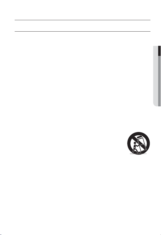
12. Use only with the cart, stand, tripod, bracket, or table specified by
the manufacturer, or sold with the apparatus. When a cart is used,
use caution when moving the cart/apparatus combination to avoid
injury from tip-over.
13. Unplug this apparatus during lighting storms or when unused for
long periods of time.
14. Refer all servicing to qualified service personnel. Servicing is required when the
apparatus has been damaged in any way, such as power-supply cord or plug is
damaged, liquid has been spilled or objects have fallen into the apparatus, the apparatus
has been exposed to rain or moisture, does not operate normally, or has been dropped.
● OVERVIEW
English _3
overview
WARNING
TO REDUCE THE RISK OF FIRE OR ELECTRIC SHOCK, DO NOT EXPOSE
THIS PRODUCT TO RAIN OR MOISTURE. DO NOT INSERT ANY METALLIC
OBJECT THROUGH THE VENTILATION GRILLS OR OTHER OPENNINGS
ON THE EQUIPMENT.
Apparatus shall not be exposed to dripping or splashing and that no objects
filled with liquids, such as vases, shall be placed on the apparatus.
To prevent injury, this apparatus must be securely attached to the Wall/ceiling
in accordance with the installation instructions.
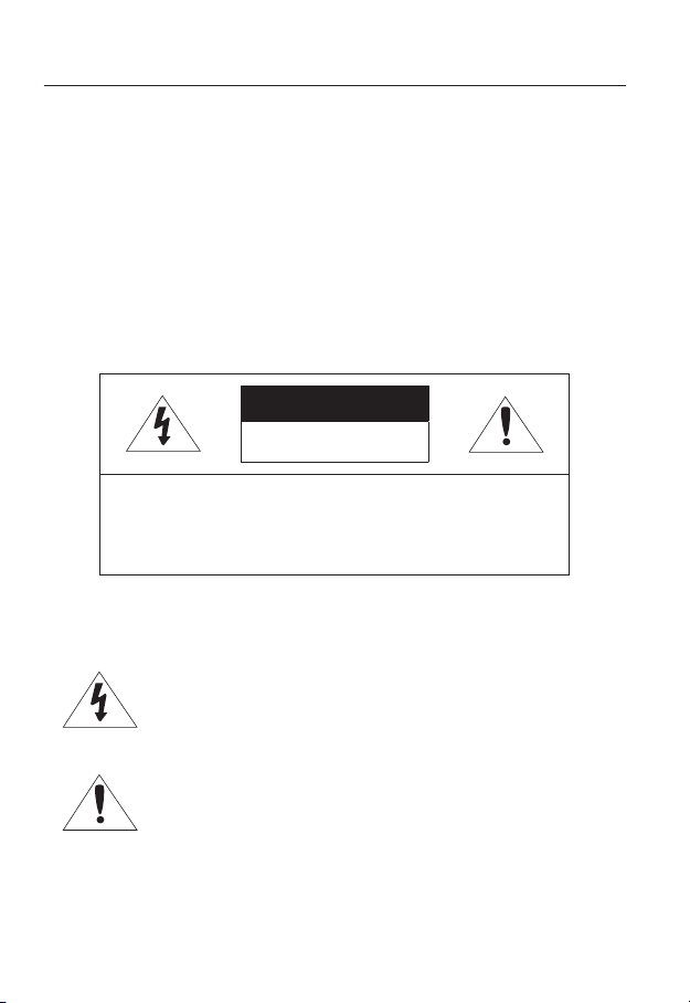
CAUTION
CAUTION
RISK OF ELECTRIC SHOCK.
DO NOT OPEN
CAUTION
REFER SERVICING TO QUALIFIED SERVICE PERSONNEL.
: TO REDUCE THE RISK OF ELECTRIC SHOCK.
DO NOT REMOVE COVER (OR BACK).
NO USER SERVICEABLE PARTS INSIDE.
EXPLANATION OF GRAPHICAL SYMBOLS
The lightning flash with arrowhead symbol, within an
equilateral triangle, is intended to alert the user to the
presence of “dangerous voltage” within the product’s
enclosure that may be of sufficient magnitude to constitute a
risk of electric shock to persons.
The exclamation point within an equilateral triangle is intended
to alert the user to the presence of important operating
and maintenance (servicing) instructions in the literature
accompanying the product.
4_ overview

Class construction
An apparatus with CLASS construction shall be connected to a MAINS
socket outlet with a protective earthing connection.
Battery
Batteries(battery pack or batteries installed) shall not be exposed to excessive
heat such as sunshine, fire or the like.
Danger of explosion if battery is incorrectly replaced.
Replace only with the same or equivalent type.
Disconnection Device
Disconnect the main plug from the apparatus, if it’s defected. And please call
a repair man in your location.
When used outside of the U.S., it may be used HAR code with fittings of
an approved agency is employed.
CAUTION
These servicing instructions are for use by qualified service personnel only.
To reduce the risk of electric shock do not perform any servicing other than
that contained in the operating instructions unless you are qualified to do so.
The BNC Out terminal of the product is provided for easier installation, and is
not recommended for monitoring purposes.
If you keep the BNC cable connected, a risk of lightening may cause damage
or malfunction to the product.
Please use the input power with just one camera and other devices must not
be connected.
● OVERVIEW
English _5

overview
Please read the following recommend safety precautions carefully.
Do not place this apparatus on an uneven surface.
Do not install on a surface where it is exposed to direct sunlight, near
heating equipment or heavy cold area.
Do not place this apparatus near conductive material.
Do not attempt to service this apparatus yourself.
Do not place a glass of water on the product.
Do not install near any magnetic sources.
Do not block any ventilation openings.
Do not place heavy items on the product.
User’s Manual is a guidance book for how to use the products.
The meaning of the symbols are shown below.
Reference : In case of providing information for helping of product’s usages
Notice : If there’s any possibility to occur any damages for the goods and
human caused by not following the instruction
Please read this manual for the safety before using of goods and keep it in
the safe place.
6_ overview

CONTENTS
OVERVIEW
3
INSTALLATION &
CONNECTION
22
NETWORK CONNECTION
AND SETUP
38
3 Important Safety Instructions
9 Product Features
9 Recomended PC Specifications
10 Recomende
Card Specifications
10 What’s Included
12 At a Glance (SND-3082)
16 At a Glance (SND-3082F)
19 At a Glance (SNV-3082)
22 Installation (SND-3082)
24 Installation (SND-3082F)
25 Installation (SNV-3082)
30 Inserting/Removing a SD Memory
Card
33 Memory Card Information
(Not Included)
34 Connecting with other Device
38 Connecting the Camera Directly
to Local Area Networking
39 Connecting the Camera Directly
to a DHCP Based DSL/Cable
Modem
40 Connecting the Camera Directly
to a PPPoE Modem
41 Connecting the Camera to a
Broadband Router with the
PPPoE/Cable Modem
42 Buttons used in IP Installer
43 Static IP Setup
47 Dynamic IP Setup
48
Port Range Forward (Port Mapping)
Setup
50 Connecting to the Camera from a
Shared Local PC
50 Connecting to the Camera from a
Remote PC via the Internet
d SD/SDHC Memory
● OVERVIEW
English _7

overview
WEB VIEWER
51
SETUP SCREEN
62
APPENDIX
90
51 Connecting to the Camera
52 Login
53 Installing ActiveX
54 Installing Silverlight Runtime
56 Using the Live Screen
59 Search and play by event
60 Search and play by time
62 Setup
62 Audio & Video Setup
71 Network Setup
78 Event Setup
85 System Setup
90 Specification
94 Product Overview
98 Troubleshooting
100 Open Source Announcement
101 License
104 GPL/LGPL Software License
8_ overview

PRODUCT FEATURES
• Multi-Streaming
This network camera can display videos in different resolutions and qualities
simultaneously using different CODECs.
• Web Browser-based Monitoring
Using the Internet web browser to display the image in a local network environment.
• Alarm
If an event occurs, the event-related video will be transferred to the email specified by the
user, or saved to the SD memory.
• Video Motion Detection
Detects a motion from the video before triggering an event.
• Auto Detection of Disconnected Network
Detects network disconnection before triggering an event.
• ONVIF Compliance
This product supports ONVIF.
For more information, refer to www.onvif.org.
RECOMENDED PC SPECIFICATIONS
• CPU : Intel(R) Core(TM)2 2.4 GHz or higher
• Operating System : Windows XP, VISTA, 7
• Resolution : 1280X1024 pixels or higher
• RAM : 2GB or higher
• Web Browser :
Chrome 8.0 or Higher, Safari 4.0 or Higher
Neither a beta test version unlike the version released in the company website nor the developer version will
be supported.
It is recommended to connect to IPv6 in Windows 7.
• Video Memory : 256MB or higher
J
Mac OS
Internet Explorer 7.0 or Higher, Firefox 3.0 or Higher,
If the driver of the video graphic adapter is not installed properly or is not the latest version, the
video may not be played properly.
For a multi-monitoring system involving at least 2 monitors, the playback performance can be
deteriorated depending on the system.
● OVERVIEW
English _9
overview
RECOMENDED SD/SDHC MEMORY CARD
SPECIFICATIONS
• 2GB ~ 32GB
• To ensure proper recording of video data, it is recommended you use a memory card that
supports at least read/write speed 10Mbps and Class 6.
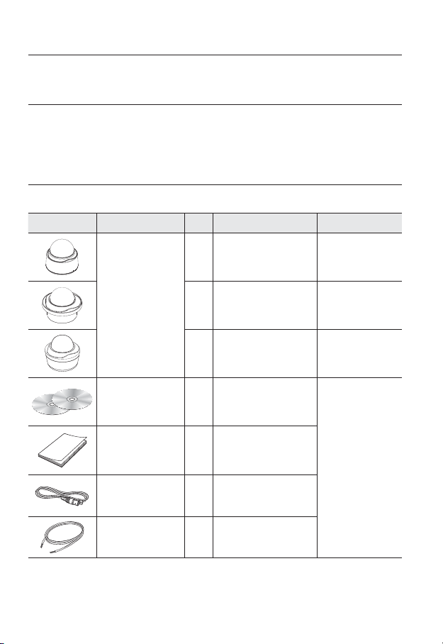
WHAT’S INCLUDED
Please check if your camera and accessories are all included in the product package.
Appearance Item Name
Quantity
Description Model Name
10_ overview
1
Camera
User Manual,
Installer S/W CD,
CMS S/W DVD
Quick Guide 1
Cable for the testing
monitor
Alarm Cable 1 Used to connect to Alarm I/O
1 SND-3082F
1 SNV-3082
2
Used to test the camera
1
connection to a portable display
device
SND-3082
SND-3082
SND-3082F
SNV-3082
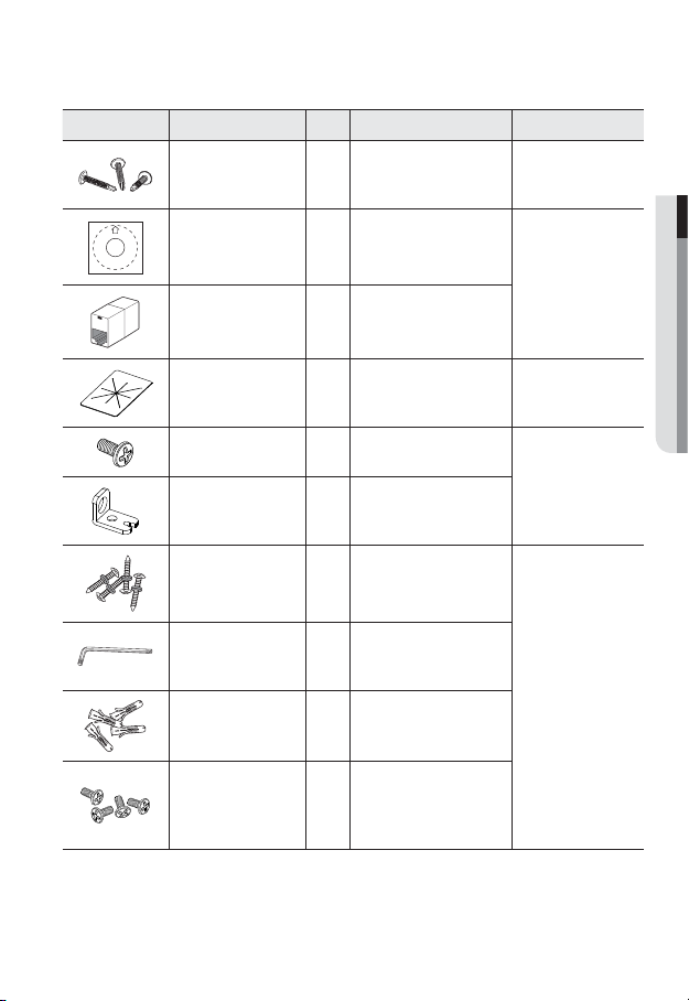
Appearance Item Name
Quantity
Description Model Name
Iron Screw 3 Used for fixing to an iron plate
Template
1
Product installation guide
SND-3082
SND-3082F
SND-3082F
SNV-3082
Jack Modular 1 LAN cable gender
Dustproof Plate 1 Preventing dust inflow SND-3082
Tapping Screw 1 Used to fix the safety bracket
SND-3082F
Bracket Safety 1 Safety Bracket
ASSY-Tapping Screw
L Wrench
Plastic Anchor
Used for installation on the wall or
4
1
ceiling
Used to remove/fix the dome
cover
For fixing a screw, Inserted in
4
a hole (reinforced anchoring
SNV-3082
force)
Used for assembling the dome
Machine Screws 4
case when installing the product
on the pipe, wall mount, etc. or
blocking a hole.
● OVERVIEW
English _11
overview
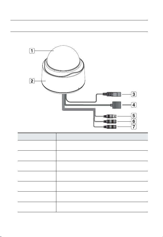
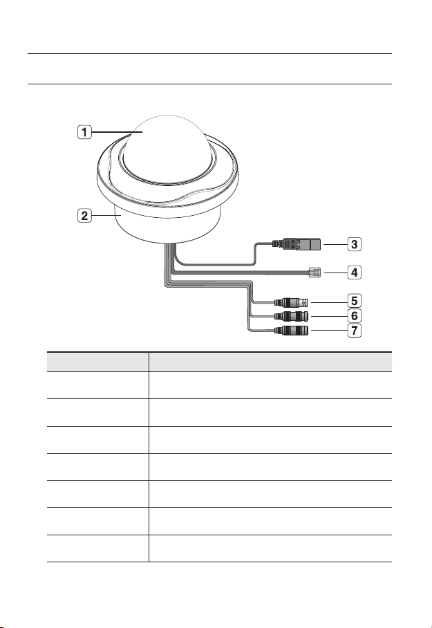
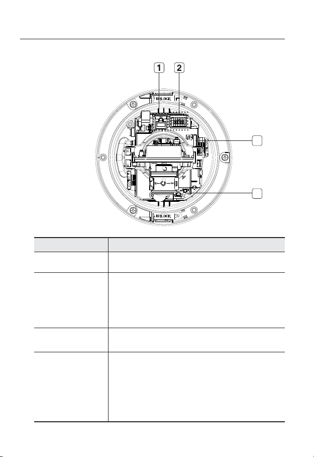
AT A GLANCE (SND-3082)
Appearance
Item Description
Top cover
Case cover used to protect the lens and the main unit.
Camera Case
b
Power Port
c
Network Port
Video Out Port
Audio In Jack
Audio Out Jack
12_ overview
Covers the lens and camera body.
Used to plug the power cable.
Used to connect a PoE or Ethernet cable.
Analog video output port. (for installation)
Used to connect to a microphone.
Used to connect to speakers.
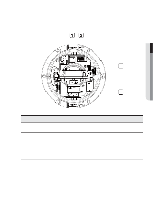
Inside
● OVERVIEW
1
4
Item Description
Network Port Used to connect a PoE or Ethernet cable.
Alarm In / Out
b
terminals
SD Memory Card
c
Compartment
Reset Button
Alarm in/out terminals can be configured as follows:
- ALARM IN :
- ALARM OUT : Used to connect the alarm output signal.
- ALARM COM : Common port where the alarm output signal is connected.
- GND : Used for earth-grounding.
Compartment for the SD memory card.
Resets the camera settings to the default.
Press and hold for about 5 seconds to reboot the system.
J
DHCP can be enabled. If there is no DHCP server in the network, you
must run the IP Installer program to change the basic network settings
such as IP address, Subnet mask, Gateway, etc., before you can
connect to the network.
Used to connect the alarm input signal.
If you reset the camera, the network settings will be adjusted so that
2
3
English _13
overview
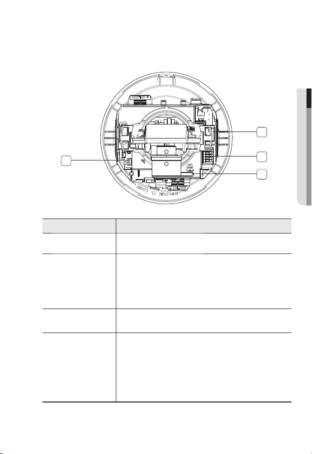
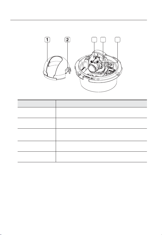
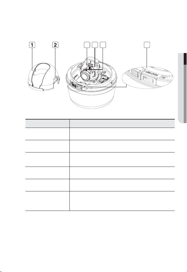
Components
1
2
4 5
7
3
Lens
6
14_ overview
8
9
Item Description
Inner Cover Cover used to protect the main unit.
Wing-Side Hook Tap on either end to remove the inner cover.
b
Monitor Out
c
Zoom Lever Used to adjust or fix the zoom factor of the lens.
Focus Lever Turn it to the left or right to adjust the focus; turn it clockwise to fix the focus.
Tilt Screw Used to adjust or fix the tilt of the lens.
Bracket Used to install the camera on the wall or ceiling with the screws.
Wiring Cover
Release Lock
The Test Monitor Cable is connected to a portable displayer and used for
testing the camera.
If you drill a hole in the wiring cover for wiring, remove
the cover and attach the provided dustproof plate to it,
and arrange the cables through the plate.
The dust-proof plate is to prevent outside dust from
inflow to the wiring compartment.
If you want to remove the bracket from the main unit or remove the camera
from the bracket, push this out and turn the main unit in the <UNLOCK>
direction.
● OVERVIEW
English _15
overview
AT A GLANCE (SND-3082F)
Appearance
Item Description
Top cover
Case cover used to protect the lens and the main unit.
Camera Case
b
Power Port
c
Network Port
Video Out Port
Audio In Jack
Audio Out Jack
16_ overview
Covers the lens and camera body.
Used to plug the power cable.
Used to connect a PoE or Ethernet cable.
Analog video output port. (for installation)
Used to connect to a microphone.
Used to connect to speakers.
Inside
Item Description
Network Port Used to connect a PoE or Ethernet cable.
Alarm in/out terminals can be configured as follows:
Alarm In / Out
b
terminals
SD Memory Card
c
Compartment
Reset Button
- ALARM IN :
- ALARM OUT : Used to connect the alarm output signal.
- ALARM COM : Common port where the alarm output signal is connected.
- GND : Used for earth-grounding.
Compartment for the SD memory card.
Resets the camera settings to the default.
Press and hold for about 5 seconds to reboot the system.
J
DHCP can be enabled. If there is no DHCP server in the network, you
must run the IP Installer program to change the basic network settings
such as IP address, Subnet mask, Gateway, etc., before you can
connect to the network.
Used to connect the alarm input signal.
If you reset the camera, the network settings will be adjusted so that
● OVERVIEW
3
4
English _17
overview
Components
Item Description
Inner Cover Cover used to protect the main unit.
Wing-Side Hook Tap on either end to remove the inner cover.
b
Monitor Out
c
Zoom Lever Used to adjust or fix the zoom factor of the lens.
Focus Lever Turn it to the left or right to adjust the focus; turn it clockwise to fix the focus.
4 53
The Test Monitor Cable is connected to a portable displayer and used for
testing the camera.
18_ overview
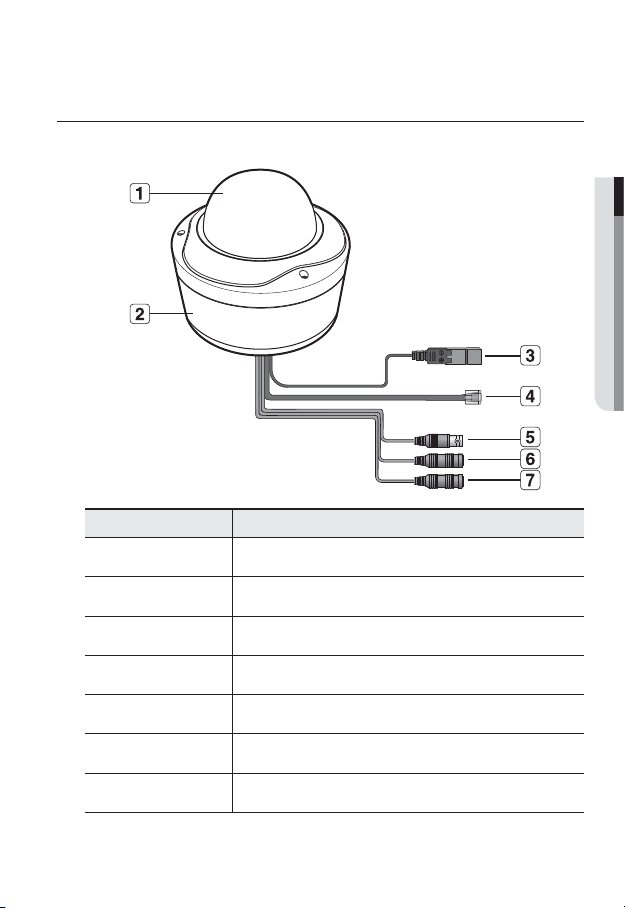
AT A GLANCE (SNV-3082)
Appearance
Item Description
Top cover
Case cover used to protect the lens and the main unit.
● OVERVIEW
b
c
Camera Case
Power Port
Network Port
Video Out Port
Audio In Jack
Audio Out Jack
Covers the lens and camera body.
Used to plug the power cable.
Used to connect a PoE or Ethernet cable.
Analog video output port. (for installation)
Used to connect to a microphone.
Used to connect to speakers.
English _19
overview
Inside
Item Description
Network Port Used to connect a PoE or Ethernet cable.
Alarm In / Out
b
terminals
SD Memory Card
c
Compartment
Reset Button
3
4
Alarm in/out terminals can be configured as follows:
- ALARM IN :
- ALARM OUT : Used to connect the alarm output signal.
- ALARM COM : Common port where the alarm output signal is connected.
- GND : Used for earth-grounding.
Compartment for the SD memory card.
Resets the camera settings to the default.
Press and hold for about 5 seconds to reboot the system.
J
DHCP can be enabled. If there is no DHCP server in the network, you
must run the IP Installer program to change the basic network settings
such as IP address, Subnet mask, Gateway, etc., before you can
connect to the network.
Used to connect the alarm input signal.
If you reset the camera, the network settings will be adjusted so that
20_ overview
Components
3 4 5 6
Item Description
Inner Cover Cover used to protect the main unit.
Wing-Side Hook Tap on either end to remove the inner cover.
b
Monitor Out
c
Zoom Lever Used to adjust or fix the zoom factor of the lens.
Focus Lever Turn it to the left or right to adjust the focus; turn it clockwise to fix the focus.
Release Lock
The Test Monitor Cable is connected to a portable displayer and used for
testing the camera.
If you want to remove the bracket from the main unit or remove the camera
from the bracket, push this out and turn the main unit in the <UNLOCK>
direction.
● OVERVIEW
English _21
installation & connection
Precautions before installation
Ensure you read out the following instructions before installing the camera:
• Select an installation site (ceiling or wall) that can endure at least 5 times of the camera
weight.
• Stuck-in or peeled-off cables can cause damage to the product or a fire.
• For safety purposes, keep anyone else away from the installation site.
And put aside personal belongings from the site, just in case.
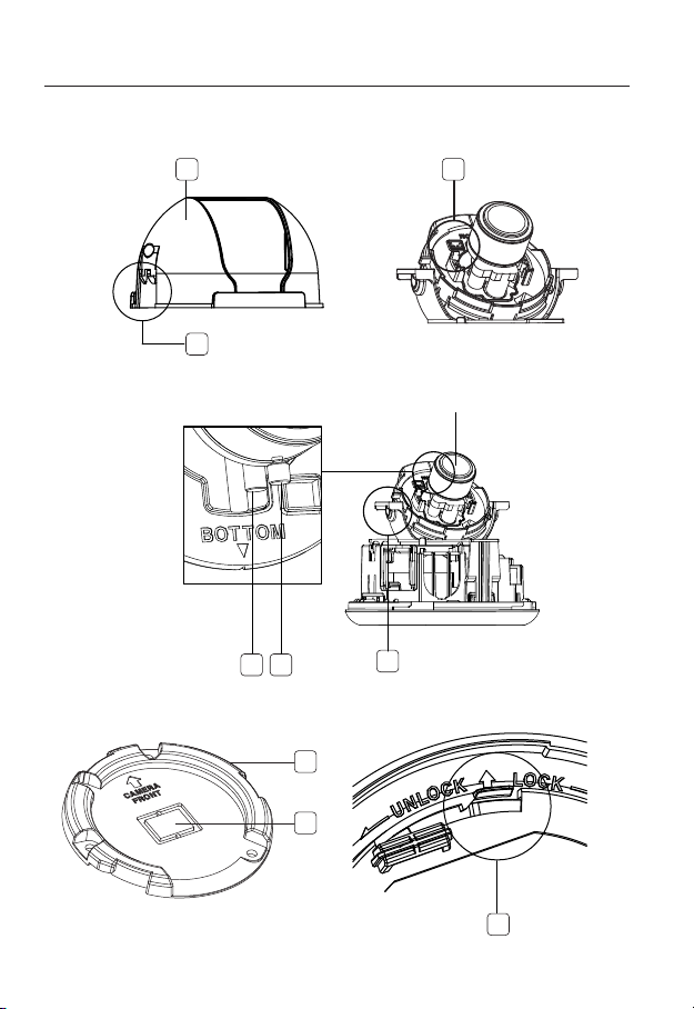
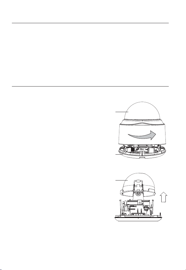
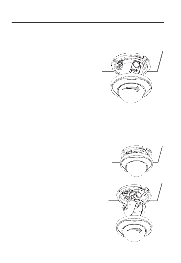
INSTALLATION (SND-3082)
Disassembling
1. Take the camera body with one hand
and take the top cover with the other
hand. Then, turn the cover counter
clockwise to remove it.
Top cover
Camera Body
2. Gently press on either side of the inner
cover to remove it.
22_ installation & connection
Inner Cover
3.
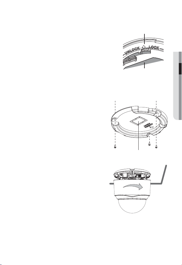
Hold down the lock lever in the outer direction as shown
and turn the camera body in the <UNLOCK> direction
(counter clockwise) to remove the bracket from the
body.
If it fails, take the bottom hole of the bracket and turn the
bracket in the <LOCK> direction (clockwise) to remove it.
Camera Body
Bracket
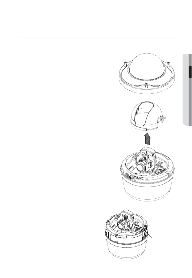
Installation
1. Use the provided screws (x3) to fix the bracket to a desired position (ceiling or wall).
Ensure that the <CAMERA FRONT> label on the bracket faces the direction for camera monitoring.
2. Arrange the cables through the bracket to
the ceiling or wall.
If you drill a hole in the ceiling cover for wiring, press
hard to remove the cover and attach the dust-proof
plate to it, and arrange the cables through the plate.
If you intend to arrange the cables without drilling a
hole, use the empty area opposite to the <CAMERA
FRONT> label side for the wiring purpose.
3.
Mount the camera body onto the bracket.
Align the marking hole of the camera body with
the <CAMERA FRONT> label of the bracket,
and turn the body in the <LOCK> direction.
4.
Refer to “Adjusting the monitoring direction
for the camera” to adjust the lens in a desired
direction.
5. Close the top cover.
Fit the top cover into the fixing tips of the camera
body and turn the cover clockwise.
Wiring Cover
● INSTALLATION & CONNECTION
English _23
installation & connection
INSTALLATION (SND-3082F)
Installation
1. Use the provided template to drill one hole for
the camera, and one for the screw (5 mm in
diameter, at least 35 mm in depth), and insert
the plastic anchor (HUR 5) to the end of the
screw hole.
2. Connect and arrange the necessary cables
lest that they should be damaged or twisted
while installing the camera.
3. Insert the camera body into the hole so that it
fits to the camera hole, and fix the body using
the ASSY tapping screws (TH M4xL30). (x3)
4. Refer to “Adjusting the monitoring direction for the camera” to adjust the lens in a
desired direction.
5. Close the top cover.
Fit the top cover into the fixing tips of the camera body and turn the cover clockwise.
Ceiling Mount
1.
Use the provided template to drill one hole for the
camera, and one for the screw (5 mm in diameter,
at least 35 mm in depth), and insert the plastic
anchor (HUR 5) to the end of the screw hole.
2. Connect and arrange the necessary cables (power,
video, etc) lest that they should be damaged or
caught while installing the camera.
3. Insert the camera assembly into the hole
so that it fits to the camera hole, and fix the
assembly using the assembly screw tappings
(TH, M4xL30). (x3)
4. Close the dome cover.
5. Fix the cover to the main unit. Fit the protruding
part inside the cover into the corresponding
hole of the main unit, and turn the cover to fix it.
24_ installation & connection
INSTALLATION (SNV-3082)
Disassembling
1. With the provided L-shaped wrench, loosen
3 bolts on the top cover counter clockwise to
remove the cover.
Removing the top cover reveals the main unit
and inner cover.
2. To fix the camera position, hold down
both hooks of the inner cover while
lifting it up.
3. Loosen 3 screws on the camera body
counter clockwise, and pull up the
left/right LOCKER lever (in the arrow
direction) to release the lock. Then,
remove the camera from the case.
● INSTALLATION & CONNECTION
Inner Cover
LOCKER Lever
English _25
installation & connection
Installing on the ceiling directly
1. Remove the top cover from the case by referring to the “Disassembling” section.
2. Drill a hole (diameter: 5mm, depth: min 35mm) in a
desired position of the case bottom and insert the
provided plastic anchor (HUD 5) to the end.
3. Fit the bottom hole to the anchor hole and insert
and fix the ASSY taping screw (TH M4×L30).
When assembling the camera case to a junction box, select
appropriate screw holes on the case bottom for installation.
4. Connect and arrange the necessary cables lest that
they should be damaged or twisted while installing
the camera.
5. Install the camera body in the reverse order of
“Disassembling”.
6. Adjust the lens in a desired direction by referring to
the “Adjusting the monitoring direction for the camera" section.
7. Close the top cover.
To ensure waterproofing, tight up the fixing bolts using the L-wrench.
Ceiling mount
1. Remove the top cover from the case by
referring to the “Disassembling” section.
2. Use the provided template to drill one hole for
the camera, and one for the screw (5 mm in
diameter, at least 35 mm in depth), and insert
the plastic anchor (HUR 5) to the end of the
screw hole.
3. Connect and arrange the necessary cables
lest that they should be damaged or twisted
while installing the camera.
CAMERA FRONT
26_ installation & connection
4. Loosen and remove the case-fixing screws on the camera unit. (x3)
5. Insert the camera unit into the hole so that it fits to the camera hole, and fix the unit
using the ASSY tapping screws (TH M4×L30). (x3)
6. Adjust the lens in a desired direction by referring to the “Adjusting the monitoring
direction for the camera” section.
7. Close the top cover.
To ensure waterproofing, tight up the fixing bolts using the L-wrench.
Attaching to the unbundled adapter
Choose and purchase a necessary one of the following options (unbundled) that is suitable
to the installation site or for your convenience.
1. Remove the top cover from the case by referring to
the “Disassembling” section.
2. Use the provided machine screw to fix the camera
case to the unbundled adapter.
3. Connect and arrange the necessary cables lest that
they should be damaged or twisted while installing
the camera.
4. Install the camera body in the reverse order of
“Disassembling”.
5. Adjust the lens in a desired direction by referring to
the “Adjusting the monitoring direction for the camera” section.
6. Close the top cover.
To ensure waterproofing, tight up the fixing bolts using the L-wrench.
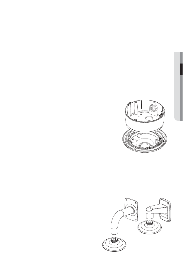
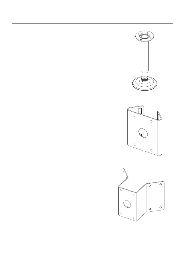
Optional Accessories for Installation
For your easier installation, you can purchase appropriate optional accessories available.
1. WALL MOUNT ADAPTOR(SBP-300WM or
SBP-300WM1)/HANGING MOUNT(SBP300HM1)
This adaptor is used when installing the
dome camera onto a wall.
● INSTALLATION & CONNECTION
English _27
installation & connection
2. CEILING MOUNT ADAPTOR(SBP-300CM)/
HANGING MOUNT(SBP-300HM1)
This adaptor is used when installing the dome
camera on a concrete ceiling.
3. POLE MOUNT ADAPTOR(SBP-300PM)
This is an adaptor for WALL MOUNT ADAPTOR
(SBP-300WM or SBP-300WM1) installation on a
pole whose diameter is bigger than 80mm.
4. CORNER MOUNT ADAPTOR (SBP-300KM)
This is an adaptor for WALL MOUNT
ADAPTOR (SBP-300WM or SBP-300WM1)
installation on the corner of wall joint.
28_ installation & connection
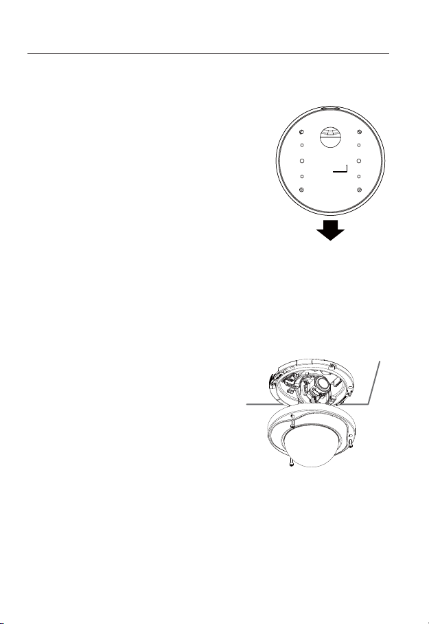
Adjusting the monitoring direction for the camera
Panning
● INSTALLATION & CONNECTION
Tilting
❖Adjusting the monitoring direction
You can adjust the camera direction only when the camera is fixed on the ceiling.
Where, rotating the camera unit to the left or right is called Pan, adjusting the tilt is called
Tilt, and turning the lens on its axis is called Rotate.
- The effective range of pan is a total of 355 degrees.
- The effective range of rotation is a total of 355 degrees.
- The effective range of tilt is a total of 90 degrees.
In some angles, the top cover may cause cutting some part of the monitoring object.
J
❖Methods of adjustment
1. After installing the camera, adjust the panning angle in consideration of the
monitoring direction.
When tilting the camera, you should adjust the horizontal angle lest that the image
be displayed reversely.
2. Adjust the rotation angle to correct the image display position (up/down/left/right).
Rotating means rotation on the basis of the rear lens unit.
3. Adjust the tilt angle so that the camera faces toward the monitoring object.
Tilt adjustment screw
Lens rotation
Adjusting the zoom and focus
Watch the camera’s real time video and rotate the “Zoom lever” to zoom in/out the subject
as you want.
Rotate the “Focus lever” until the image looks clear.
For the position of the Zoom lever and Focus lever, refer to the “Components” (page 14, 18, 21).
It is recommended to install the camera 2.5M~10M high above from the floor.
M
English _29
installation & connection
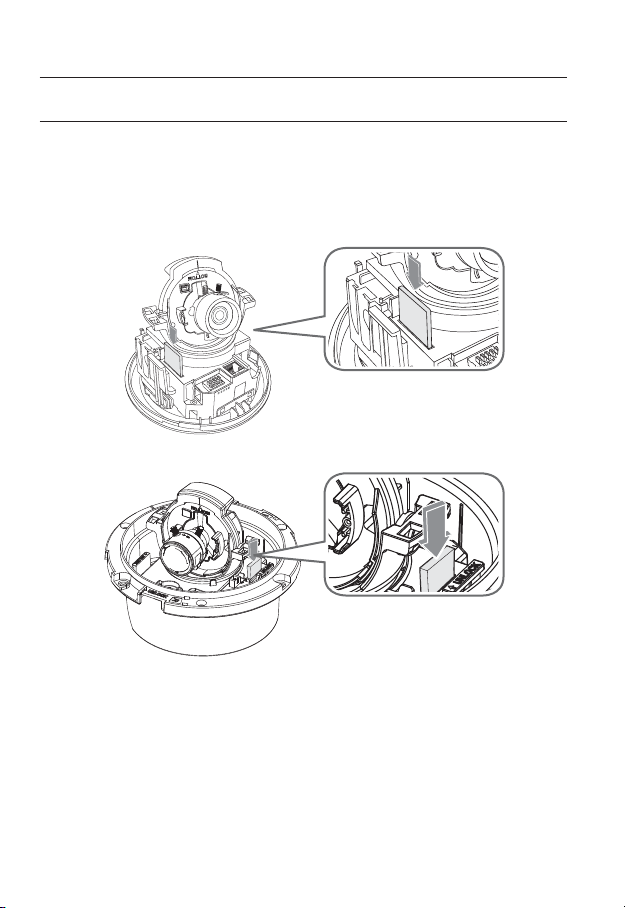
INSERTING/REMOVING A SD MEMORY CARD
Disconnect the power cable from the camera before inserting the SD memory card.
J
Inserting a SD Memory Card
Push the SD memory card in the direction of the arrow shown in the diagram.
"-"3.0
"-"3.06
(/%
"-"3.*/
"-"3.*/
65
5
<SND-3082>
30_ installation & connection
<SND-3082F>
 Loading...