

Samsung SNT-1010P User Manual

SNT-1010
SNT-1010 1CH Video Server
User’s manual
Safety instructions and precautions are designed to protect
users and prevent any property damage.
Please read and observe these instructions thoroughly before
using the SNT-1010.
AB68-00610A
2 3
Features Before You Start
Before you start, please read the following
descriptions.
Preparation Preparation
Various Communication Protocol Support
This product supports support various
communication protocols such as ARP,
HTTP and DHCP as well as TCP/IP, UDP,
SMTP for e-mail transmission and FTP
protocol.
Automatic Local IP Setting Function
This function offers an easy way of
configuring the network settings with a
minimal key input for those who are not
familiar with it.
UPnP (Universal Plug and Play) Function
It this product is connected with an IP
sharer supporting UPnP function, it
automatically provides port forwarding
that allows connections from the
external Internet.
Monitoring Through Web Browser
Monitoring Through Web Browser This
product enables watching a video through
an Internet web browser so that you can
watch a video through the Internet as you
can within the local network.
Alarm Function
If this product is connected with a
motion sensor and the sensor detects a
motion, a recorded video clip is sent
through an FTP/E-Mail registered by the
user and a signal is sent to an alarm
output port.
Motion Detection Function
If the user specifies a target area to
monitor and the motion sensor
detects a motion within that area, a
recorded video clip is sent through an
FTP/E-Mail registered by the user
and a signal is sent to an alarm output
port.
Icons for the Safety Precautions
Icon Description
Icon Name
Warning
If you do not follow the instructions marked with this label, it may cause a serious physical damage.
If you do not follow the instructions marked with this label, it may cause a serious physical damage or loss of property.
Notice
Description
Icon Name
Notice
This label indicates that the product may not work properly or the settings may be initialized.
This label indicates tips for the use of the product or shows the page numbers that can be referred to.
Note
This label indicates the settings to be set in advance of product use.
Before You Start
Description
Class A Equipment (For Office Use)
This device has been registered regarding EMI for office use only. Please the product provider and
customer keep this in mind and exchange this product for a product designed for home use if necessary.
"Underwriters Laboratories Inc. has not tested the performance or reliability of the security or
signaling aspects of this product. UL has only tested for fire, shock and casualty hazards as outlined
in UL's Standard for Safety UL 60950-1. UL Certification does not cover the performance or reliability
of the security or signaling aspects of this product.
UL MAKES NO REPRESENTATIONS, WARRANTIES OR CERTIFICATIONS WHATSOEVER
REGARDING THE PERFORMANCE OR RELIABILITY OF ANY SECURITY OR SIGNALING
RELATED FUNCTIONS OF THIS PRODUCT."
Chapter 1 Preparation
Features/Before You Start

4 5
Contents System Requirements
Chapter 1 Preparation
Features........................................................ 2
Before You Start......................................... 3
Contents ....................................................... 4
System Requirements .............................. 5
Safety Precautions .................................... 6
View of SNT-1010....................................... 8
Chapter 2
Installing and Connecting
Installing SNT-1010 ...................................11
Connecting SNT-1010 ..............................13
Chapter 4
Static IP Setting
Manual Network Setting...................................33
Automatic Network Setting.............................36
Chapter 5
Dynamic IP Setting
Dynamic IP Setting .................................37
Chapter 6
When Using an IP Sharer
Port Forwarding (Port Mapping) Setting
..... 39
Chapter 3
Network Connection & Setup
To Connect SNT-1010 to an IP sharer
with the xDSL/Cable modem..........................20
Connect SNT-1010 to an IP sharer
with local area networking
....................................25
Connect SNT-1010 directly
to a DHCP-based xDSL/Cable modem........30
Connect SNT-1010 directly to local area
networking ...........................................................31
Searching for SNT-1010 ...................................32
Chapter 9 Appendix
Resetting the System............................. 79
Trouble-shooting ....................................80
Specifications .......................................... 83
Chapter 8 Setting Up
Setting SNT-1010 ....................................49
Basic Configuration................................ 50
System Configuration............................ 57
Layout Configuration ............................. 62
Event Configuration ............................... 68
Network Configuration.......................... 76
Chapter 7 Using SNT-1010
Connecting to SNT-1010....................... 40
Installing ActiveX .................................... 43
Using the Viewer Screen....................... 44
Viewer Screen Buttons and Functions
.... 45
Recommended PC Specifications
Compatible IP Sharers
CPU : Pentium4/1.5GHz or higher (At least Pentium4/1.0GHz)
Video Memory : 128MB
Operating System : Windows XP / Windows 2000 Professional
Resolution : 1024X768 pixels or higher
RAM : 256MB or more
Web Browser : Internet Explorer 5.0 or later DirectX 8.1 or later
- LINKSYS WRT54G
- D-LINK DI-624
- NETGEAR WGT624
Chapter 1 Preparation
Contents/System Requirements
Preparation Preparation
There is a risk of damage to the product.
Do not move the product
while it is in operation.
Make sure to move or reinstall
the product after turning it off.
If you do not follow the instructions, it may cause a serious physical injury or loss of property.
Operation Related
Keep the product away
from a shaking place or
magnetic matter.
There is a risk of damage to the
product.
Avoid dropping the product or
impact on the product.
There is a danger of damage to the product.
6 7
Safety Precautions
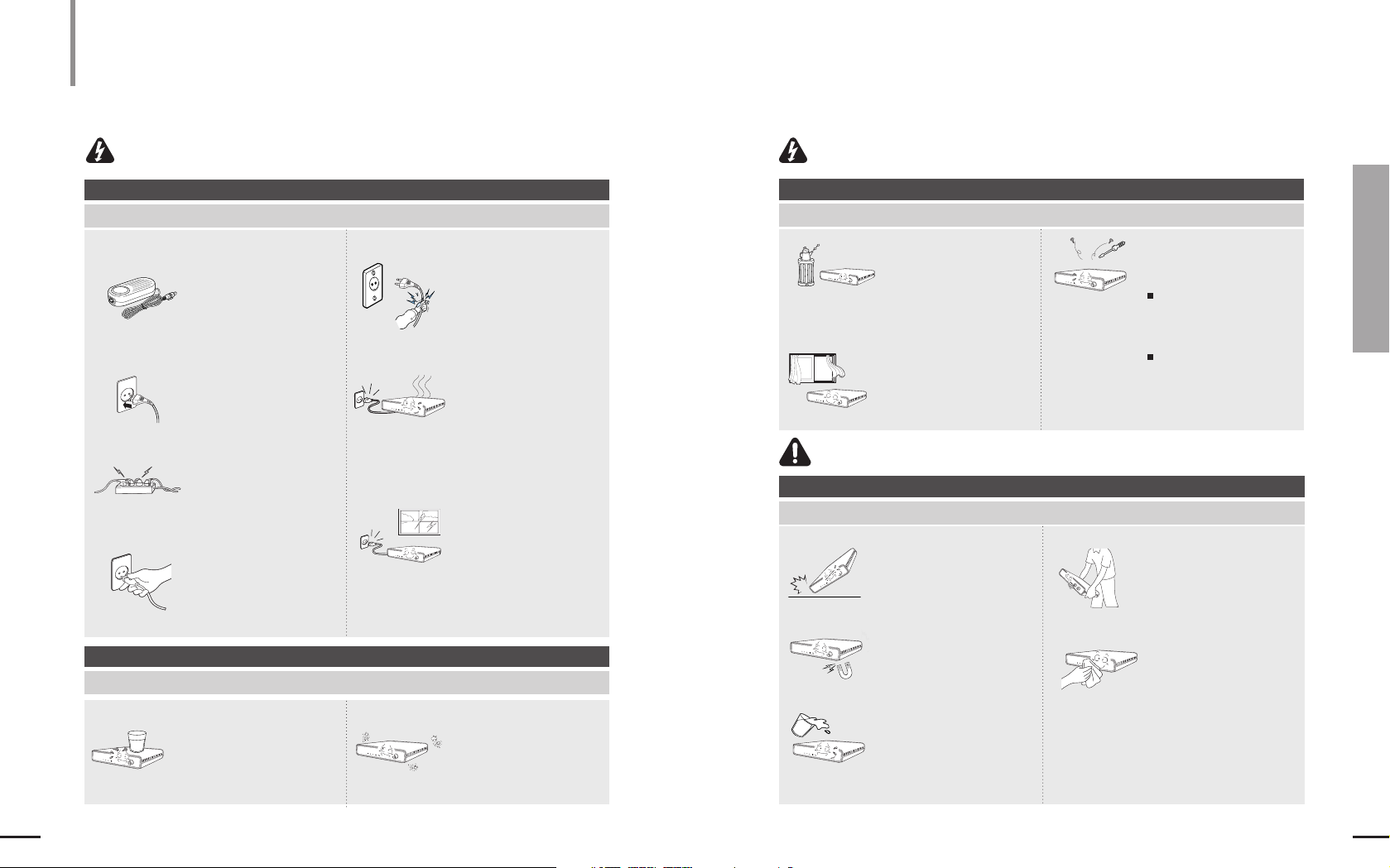
Warning
To avoid physical damage and loss of property, please
read and follow the safety precautions given below.
Chapter 1 Preparation
Safety Precautions
Preparation
If you do not follow the instructions,it may cause a serious physical damage.
Power Related
There is a risk of fire, electric shock or physical injury.
Do not bend the power
cable excessively or place
a heavy object over the
cable.
Plug the power cable firmly
so that the power plug is not
loose.
Do not hold the power plug
with a wet hand.
Use the AC adapter
authorized by the company
only. (DC 8.4V/1A)
Using an unauthorized AC adapter
may cause fire,electric shock or
malfunction.
Do not plug multiple
power cables into a wall
outlet.
It the product emits smoke
or make a strange smell,
immediately disconnect
the power and contact the
customer service.
If you continue using this
product, it may cause a fire or
electronic shock.
If you do not follow the instructions, it may cause a serious physical damage.
Operation Related
There is a risk of fire, electric shock or physical injury.
Do not spray water
directly onto the product
for cleaning.
Otherwise, it may cause fire or
electric shock.
Clean the product surface
with a soft, dry cloth.
Never use chemicals or
cleansing solutions to clean the
product, because using them
may deteriorate or remove the
painting.
In case of lightning or
thunder storm,
immediately disconnect
the power cable from
the wall outlet.
Otherwise, it may cause fire
or malfunction of the product.
Operation Related
There is a risk of fire, electric shock or physical injury.
Do not place metal matters over
SNT-1010 such as a screw driver,
coin, metal parts, etc.,or a
container filled with liquid.
Otherwise, it may cause fire, electric shock
or physical injury.
Do not install the product in a
humid,dusty or sooty place.
Otherwise, it may cause fire or
electric shock.
Do not install the product in a place
where temperature is excessively
high (50°C or higher) or low (minus
10°C or lower) or a humid place.
Otherwise, it may cause a fire or electronic
shock.
Do not install the product in a
place where the direct sunlight
reaches or near a heater. Install
the product in an airy place.
Otherwise, it may cause fire.
Do not disassemble, repair
or modify the product.
If the product does not work
properly, please contact your
product provider or customer
service center.
The company shall not be held
liable for the problem caused
by user’s disassembly or
repair.
Warning
Notice
8 9
Chapter 1 Preparation
View of SNT-1010
Preparation
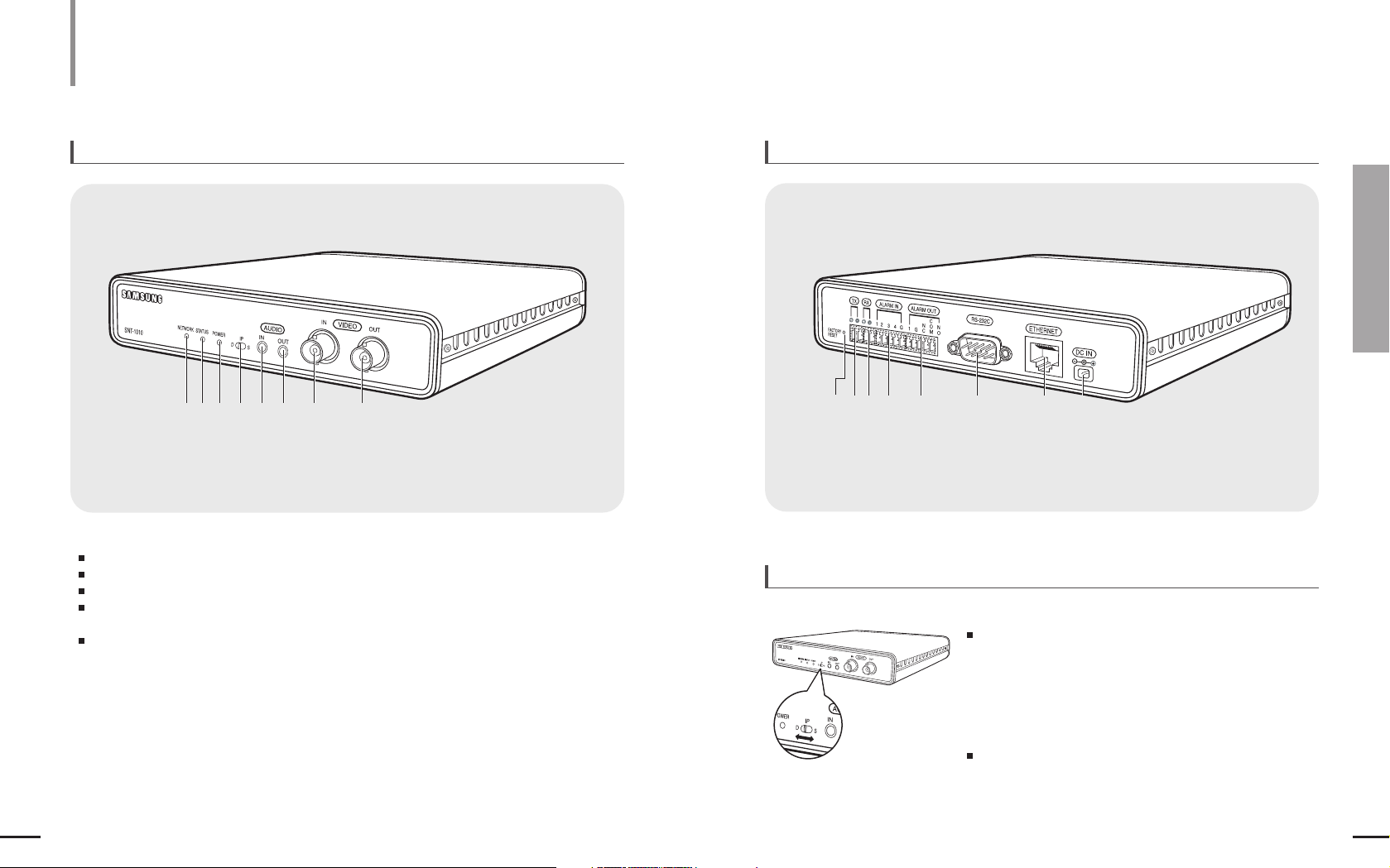
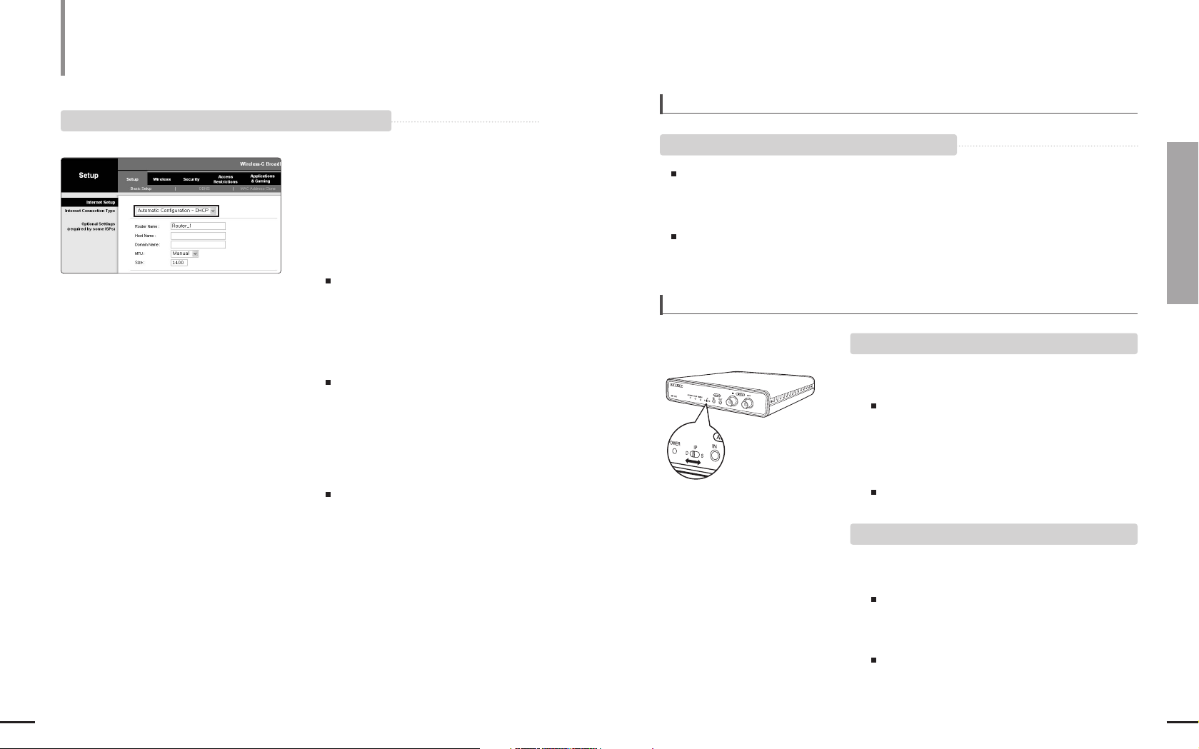
To select an IP address allocation method
View of SNT-1010
Front View
Slide the [IP Select Switch ] left or right to position it to <D>or <S>.
D (Dynamic IP) : Slide the switch to this position for the following cases.
- Select this when you install SNT-1010 on the IP sharer
and use the DHCP function of the sharer to
automatically obtain the IP address.
- When SNT-1010 is installed onto an xDSL
(e.g.VDSL)or Cable modem supporting DHCP.
- When the IP address is automatically allocated by
DHCP without manual allocation.
S (Static IP) : Slide the switch to this position when you directly enter an
IP address using the IP Installer.
- The factory default setting is Static IP.
- Select this if you are informed of IP address, Gateway and
Subnet Mask information.
1
Network LED
2 Status LED (
*
)
3 Power LED
4
IP Select Switch
5
Audio IN Port
6 Audio OUT Port
7
Video IN Port
8
Video OUT Port
12 3 4 5 6 7
8
Rear View
1
FACTORY RESET Button ( *)
2 TX Port
3 RX Port
4 Alarm IN Port
5 Alarm OUT Port
6 RS-232C Port
7 Ethernet Port
8 Power Port
1234 5 6 7
8
*
Status LED (Indicates the operational status of SNT-1010).
Green : Normal operation
Blinking Green : If the IP setting has failed in DHCP
Red : When the file upload is in process or the NTP connection has failed
Blinking Red : If SNT-1010 causes a problem or you reset the system to the factory
default, the red LED blinks 3 times.
Blinking Yellow : When SNT-1010 gets started
*
FACTORY RESET Button : This will return the settings of SNT-1010 to the factory default.
Refer to <Resetting the System> in the user guide.

1
11
Chapter 2 Installing and Connecting
Installing SNT-1010
10
Accessories
Power Cable CD Owner’s Manual
(Including Warranty)
Screws
(2 Big and 4 Small Screws)
RS-485/Alarm Port
AC Adapter
(DC 8.4V/1A)
Fixing Blocks (4)Fixing Metals (2)
The latest version of the software is available on Samsung Electronics web site (http://www.samsung.com).
Installing and Connecting
Disconnect the power cable before installing or
moving the product.
Installing SNT-1010
To install on a floor or wall.
Assemble as follows for both sides of the main body.
1
Insert the Fixing Block onto a side of the product and turn it in the arrow
direction as described in the figure.
2
Fix the Fixing Metal onto the Fixing Block using the 2 screws (small).
Fix the Fixing Metal so that the bottom of the Fixing Metal faces the floor or wall.
3
Fix the Fixing Metal on the floor or wall using one screw (big).
2
3
Preparation
View of SNT-1010
(Continued)
12 13
Chapter 2 Installing and Connecting
Installing SNT-1010/Connecting SNT-1010
If you connect the SNT-1010 to the Internet and
setup the network settings,you can monitor the
picture of the connected camera in real-time.
To install onto a dedicated shelf
When you install this product on a wall, check if the wall is strong enough to sustain the weight of the product.
Dropping of this product may cause an injury when it is installed on a wall. Therefore fix the product firmly when
you install this product on a wall.
This product is designed for indoor use. Install this product in a dry place so that it is not wet by rain or snow.
Notice
1
Insert the Fixing Block onto a side of the product and turn it in the arrow direction
as described in the figure.
2
Fix the Fixing Metal onto the Fixing Block using the 2 screws (small).
Fix the Fixing Metal so that the bottom of the Fixing Metal faces forward.
3
Fix the Fixing Metal on the shelf using one screw (big).
Assemble as follows for both sides of the main body.
1
2
3
Installing and Connecting
Installing SNT-1010 (Continued)
Connecting SNT-1010
Installing and Connecting
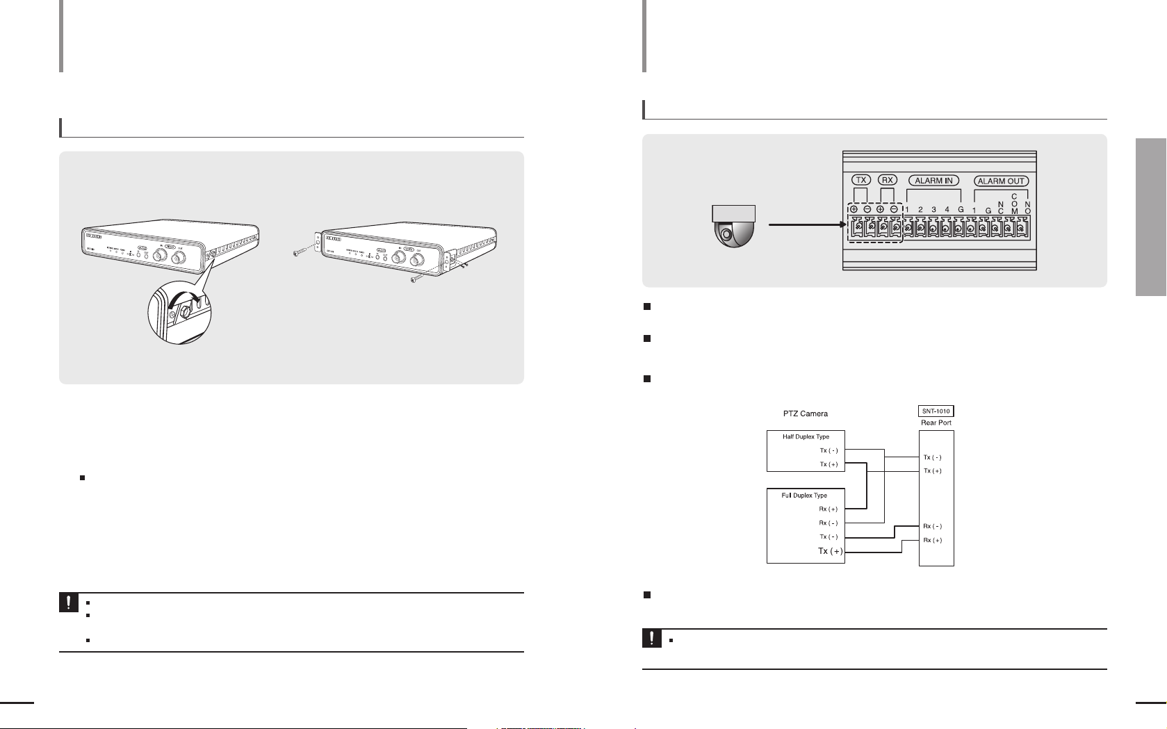
To connect to RS-485
Ensure that the RS-485 device you want to use is compatible with SNT-1010.
Ensure that you connect to the RS-485 device so it fits the polarity of the port.
Notice
You can use the rear port of SNT-1010 to connect to the RS-485 device.
You can install and control over a PTZ camera that supports RS-485 communications.
You can make the connection in either Half Duplex or Full Duplex.
The baud rate available is : 600/1200/2400/4800/9600/19200/38400.

15
Chapter 2 Installing and Connecting
Connecting SNT-1010
14
RS-485, ALARM I/O Block Diagram
To Connect a Camera Input
To Connect a Monitor Output
Connecting SNT-1010 (Continued)
Installing and Connecting
1
Connect the [VIDEO OUT ] port of the
SNT-1010 and the VIDEO IN port of the
monitor.
2
Connect the [AUDIO OUT ] port of the
SNT-1010 and the AUDIO IN port of the
monitor.
1
1
1
2
2
Connect the [VIDEO IN ] port of the
SNT-1010 and the VIDEO OUT port of
the camera.
2
Connect the [AUDIO IN ] port of the SNT-1010
and the AUDIO OUT port of the camera.
If the camera provides an AUDIO OUT port.
SNT-1010
SNT-1010
Camera
Monitor
17
Chapter 2 Installing and Connecting
Connecting the SNT-1010
16
Connecting SNT-1010 (Continued)
Installing and Connecting
LINE-OUT
SPEAKER
Pre-Amp
Network
Pre-Amp
Computer
Pre-Amp
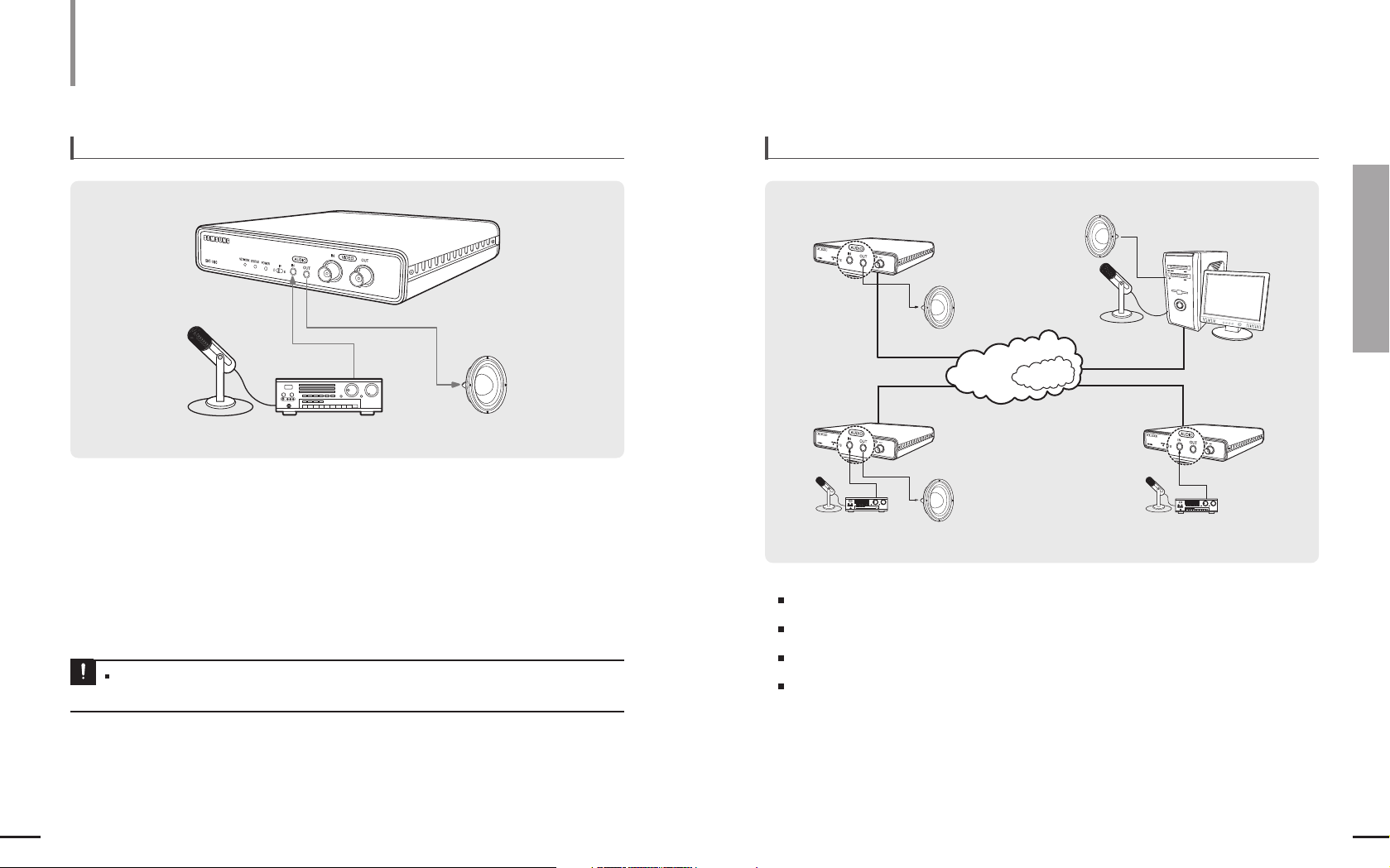
To connect to Audio Input/Output Audio I/O Block Diagram
1
Connect the [AUDIO IN ] port of the SNT-1010 with the LINE OUT portof the amplifier that the
microphone is connected to.
Audio Codec :G.711 PCM, µ-law 64kbps 8kHz sampling
Full duplex Audio
Audio in : Used for mono signal line input (Max.2.4 Vpp)
Audio out : Used for mono signal line output (Max.2.4 Vpp)
Line out impedance :600ohm
2
Connect the [AUDIO OUT ] port of the SNT-1010 with the LINE IN port of the speaker.
SPEAKER
Microphone
Microphone
PC
If you connect the microphone to the AUDIO OUT port, you can't hear a sound.
MIC IN is not enabled.
Notice
19
Chapter 2 Installing and Connecting
Connecting the SNT-1010/Network Connection &Setup
18
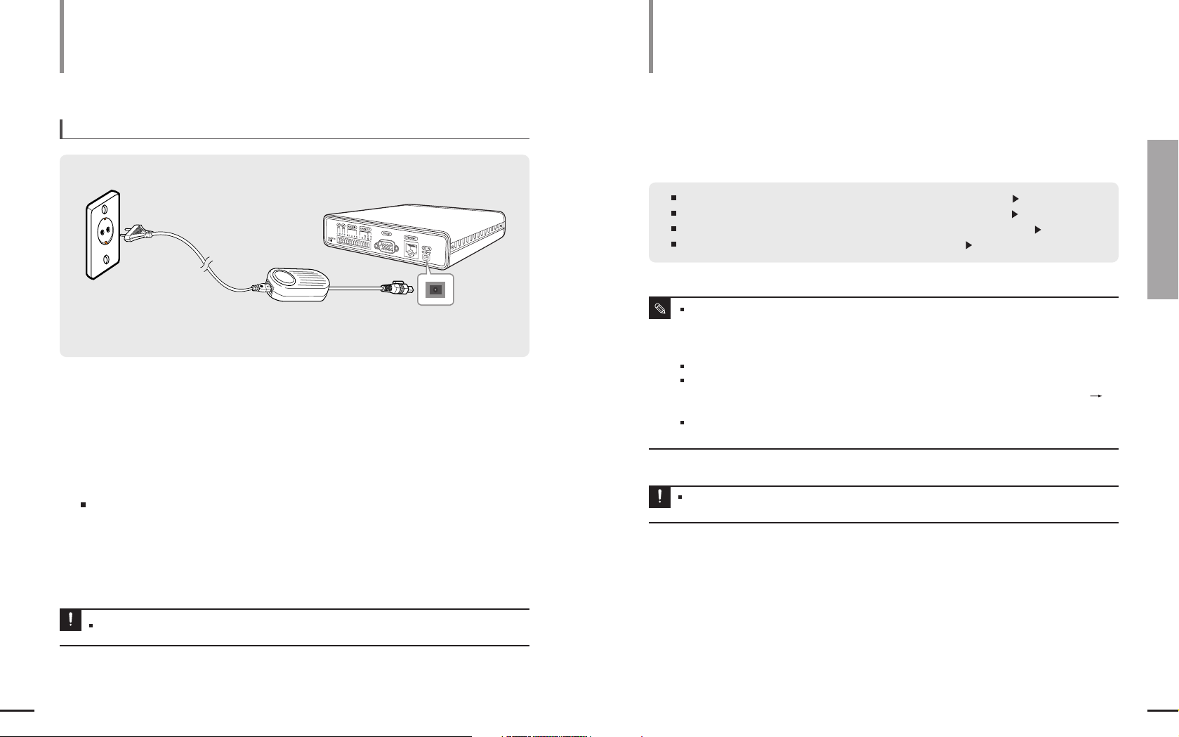
To Connect the Power
1
Connect the AC adapter to the Power port of the SNT-1010.
2
Connect the power cable to the AC adapter.
3
Plug the power plug into the wall outlet.
If the power is connected,the [POWER]LED is turned on.
Use AC adapter authorized by the company only. (DC 8.4V/1A)
Notice
AC Adapter
SNT-1010
Power Cable
12
3
Network Connection & Setup
SNT-1010 compliant IP sharers are as listed below.
- LINKSYS WRT54G
- D-LINK DI-624
- NETGEAR WGT624
Do not use other IP sharers than SNT-1010 authorized ones.Otherwise, it can cause a network error.
Depending on the performance of the PC (Viewer installed)or the network,the video transmission can be
delayed or even disconnected. For soft video transmission,you can set the bandwidth in <NETWORK>
<STREAMING SETUP> under the SNT-1010 setup menu.
LINKSYS WRT54G IP sharer is taken example for the description of the IP settings in this manual.
For more information on the third party’s IP sharer, refer to the product‘s documentation.
Note
Connect SNT-1010 to an IP sharer with a xDSL/Cable modem Page 20
Connect SNT-1010 to an IP sharer with local area networking Page 25
Connect SNT-1010 directly to a DHCP-based xDSL/Cable modem Page 30
Connect SNT--1010 directly to local area networking Page 31
SNT-1010 network connection and setup processes are given as follows.
You can set up the SNT-1010 network settings according to your network configurations.
The IP and MAC addresses used in this manual are for illustrative purposes only.Therefore,you must refer to
the network settings of your PC and do not enter the addresses presented in this manual.
Notice
Connecting SNT-1010 (Continued)
Installing and Connecting
21
Chapter 3 Network Connection &Setup
20
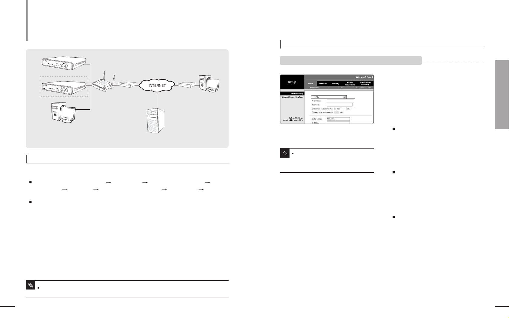
To Connect SNT-1010 to an IP sharer with the xDSL/Cable modem
This is for a small network environment
such as homes, SOHO and ordinary shops.
Network Connection & Setup
To Connect SNT-1010 to an IP sharer
with the xDSL/Cable modem
To configure the network settings of the local PC connected to an IP sharer, follow the instructions below.
SNT-1010 1
SNT-1010 2
Local PC
IP Sharer
xDSL or
Cable Modem
xDSL or
Cable Modem
External Remote PC
DDNS Server
(Data Center, KOREA)
Select : <Network Neighborhood> <Properties> <Local Area Connection>
<Properties> <General> <Internet Protocol (TCP/IP)> <Properties>
<Obtain an IP address automatically> or <Use the following IP address>
Follow the instructions below if you select <Use the following IP address>:
ex1) If the address (LAN IP)of the IP sharer is 192.168.1.1
IP address : 192.168.1.100
Subnet Mask : 255.255.255.0
Default Gateway : 192.168.1.1
ex2) If the address (LAN IP)of the IP sharer is 192.168.0.1
IP address : 192.168.1.100
Subnet Mask : 255.255.255.0
Default Gateway : 192.168.0.1
ex3) If the address (LAN IP)of the IP sharer is 192.168.xxx.1
IP address : 192.168.1.100
Subnet Mask : 255.255.255.0
Default Gateway : 192.168.xxx.1
[ STEP 1 ] To configure the network settings of the local PC connected to an IP sharer
For the address of the IP sharer, refer to the product’s documentation.
Note
1
Launch an Internet browser on the local PC
connected to the IP Sharer.
2
Enter the IP Sharer’s address in the
address bar of the browser.
ex) http://192.168.1.1 ,http://192.168.0.1 or
http://192.168.xxx.1
For the address of the IP sharer, refer to the
product’s documentation.
3
When the IP Sharer is connected, the login
window appears and prompts you to enter
the password.
For the login IP and the password, refer to the
IP sharer’s documentation.
4
When done, you will see the setup window
of the IP sharer. In the setup menu, select
“PPPoE” for Internet Connection Type.
For the menu location of Internet Connection
Type and PPPoE, refer to the IP sharer’s
documentation.
5
Enter the <User Name> and <Password>
provided by your ISP (Internet Service
Provider) before you can access the
Internet.
6
When done, click the <Save> or <Apply>
button to save the settings.
To check if your xDSL modem uses
PPPoE or DHCP, contact the Internet
service provider.
Note
4
5
[ STEP 2 ] To connect the IP sharer to a xDSL /Cable modem
A. If the IP sharer is connected to an xDSL modem using PPPoE
23
Chapter 3 Network Connection &Setup
To Connect SNT-1010 to an IP sharer with the xDSL/Cable modem
22
1
Launch an Internet browser on the local PC
connected to the IP Sharer.
2
Enter the IP Sharer’s address in the
address bar of the browser.
ex) http://192.168.1.1 ,http://192.168.0.1 or
http://192.168.xxx.1
For the address of the IP sharer, refer to the
product’s documentation.
3
When the IP Sharer is connected, the login
window appears and prompts you to enter
the password.
For the login IP and the password, refer to the
IP sharer’s documentation.
4
When done, you will see the setup window
of the IP sharer. In the setup menu, select
“Automatic Configuration-DHCP ” for
Internet Connection Type.
For the menu location of Internet Connection
Type and DHCP, refer to the IP sharer’s
documentation.
5
Some Internet service providers may
require additional information such as user
ID, password or host name for the
connection using DHCP. For more
information, contact your Internet service
provider.
6
When done, click the <Save> or <Apply>
button to save the settings.
4
B. If the IP sharer is connected to an xDSL modem using DHCP
Network Connection & Setup
To Connect SNT-1010 to an IP sharer with the xDSL/Cable modem
(Continued)
[STEP 3 ] To check if the IP sharer is connected to the xDSL /Cable modem properly
[STEP 4 ] To connect SNT-1010 to the IP sharer
Select <Status> from the Settings menu of the IP Sharer
A. If using Dynamic IP mode of SNT-1010
B. If using Static IP mode of SNT-1010
If it is properly connected, <IP Address>, <Subnet Mask> and <Gateway> provided by your
ISP are displayed. Please remember these values because they are required so that an
external remote computer of the IP sharer connects to SNT-1010. However, note that certain
ISPs change the settings of <IP Address>, <Subnet Mask>and <Gateway>on a regular basis
If the IP sharer is not properly connected, press the <Connect> button to try to reconnect or
check if the settings of the IP sharer are correct.
1.Position the IP selection switch to D (Dynamic IP).
2.SNT-1010 is connected to the IP sharer using the Direct LAN
Cable (UTP cable).
SNT-1010 does not come with the Direct LAN cable.
You have to purchase it separately.
3.Connect SNT-1010 to the power source.
4.
When SNT-1010 starts, it automatically obtains an IP address from
the IP sharer.
5.You can check the dynamic IP address from the IP sharer by using
the IP installer on your PC.
For how to use the IP installer, refer to “Dynamic IP Setting:
Check Dynamic IP” on page 38.
1.Position the IP selection switch to S (Static IP).
2.SNT-1010 is connected to the IP sharer using the Direct LAN
Cable (UTP cable).
SNT-1010 does not come with the Direct LAN cable.
You have to purchase it separately.
3.Connect SNT-1010 to the power source.
4.Use the IP installer on your local PC to configure the
<IP address>, <Subnet Mask>, <Gateway>and <Port>settings.
For how to use the IP installer, refer to “Static IP Setting” on
page 33.

25
Chapter 3 Network Connection &Setup
To Connect SNT-1010 to an IP sharer with the xDSL/Cable modem/Connect SNT-1010 to an IP sharer with local area networking
24
[ STEP 5 ] To connect a local PC in the IP sharer to SNT-1010
[ STEP 6 ] To connect to SNT-1010 from a remote PC
Network Connection & Setup
To Connect SNT-1010 to an IP sharer with the xDSL/Cable modem
(Continued)
1
Run the IP Installer on your local PC and search for SNT-1010.
2
If found, double-click the SNT-1010 to start the Internet browser and try to connect to
SNT-1010. Alternately, launch the Internet browser manually and enter the IP address of the
SNT-1010 found in the address bar to connect to it.
ex) http://192.168.1.2
1
You can’t use the IP Installer on a remote PC that is not connected to the IP sharer.
This is because the IP Installer does not work on the Internet.
2
You can use DDNS URL of SNT-1010 to connect to the IP sharer internal SNT-1010.
3
However, you must set the port-forwarding for the IP sharer before you can connect to the IP
sharer internal SNT-1010 from a remote PC.
For more information on the port-forwarding, refer to Use IP Sharer: Port Forwarding Setting
(Port Mapping).
4
When the port forwarding is done, run the Internet browser on the remote PC and enter the
DDNS URL address or, the Internet IP address of the IP sharer in the address bar for
connecting to SNT-1010.
ex) http://mfffe42.websamsung.net
For the DDNS URL address, refer to “To check the DDNS address” on page 41.
Local PC
SNT-1010 1
SNT-1010 2
IP Sharer External PC
Firewall
IP Sharer
Switch
HUB
External
Remote PC
DDNS Server
(Data Center, KOREA)
Network Connection & Setup
Connect SNT-1010 to an IP sharer with local area networking
This is for a large network environment such
as corporate office, building, public office
and factory.
To configure the network settings of the local PC connected to an IP sharer, follow the instructions below.
Select : <Network Neighborhood> <Properties> <Local Area Connection>
<Properties> <General> <Internet Protocol (TCP/IP)> <Properties>
<Obtain an IP address automatically> or <Use the following IP address>
Follow the instructions below if you select <Use the following IP address>:
ex1) If the address (LAN IP)of the IP sharer is 192.168.1.1
IP address : 192.168.1.100
Subnet Mask : 255.255.255.0
Default Gateway : 192.168.1.1
ex2) If the address (LAN IP)of the IP sharer is 192.168.0.1
IP address : 192.168.1.100
Subnet Mask : 255.255.255.0
Default Gateway : 192.168.0.1
ex3) If the address (LAN IP)of the IP sharer is 192.168.xxx.1
IP address : 192.168.1.100
Subnet Mask : 255.255.255.0
Default Gateway : 192.168.xxx.1
[ STEP 1 ] To configure the network settings of the local PC connected to an IP sharer
For the address of the IP sharer, refer to the product’s documentation.
Note

27
Chapter 3 Network Connection &Setup
Connect SNT-1010 to an IP sharer with local area networking
26
1
Launch an Internet browser on the local PC
connected to the IP Sharer.
2
Enter the IP Sharer’s address in the
address bar of the browser.
ex) http://192.168.1.1 ,http://192.168.0.1 or
http://192.168.xxx.1
For the address of the IP sharer, refer to the
product’s documentation.
3
When the IP Sharer is connected, the login
window appears and prompts you to enter
the password.
For the login IP and the password, refer to the
IP sharer’s documentation.
4
When done, you will see the setup window
of the IP sharer. In the setup menu, select
“Static IP” for Internet Connection Type.
For the menu location of Internet Connection
Type, refer to the IP sharer’s documentation.
5
Enter <IP Address>, <Subnet Mask>,
<Gateway> and <DNS> to connect to the
Internet.
For the value for each of the fields, contact your
network administrator.
6
When done, click the <Save> or <Apply>
button to save the settings.
[ STEP 2 ] To configure the network settings of the IP Sharer
4
5
Network Connection & Setup
Connect SNT-1010 to an IP sharer with local area networking (Continued)
[ STEP 3 ] To connect SNT-1010 to the IP sharer
A. If using Dynamic IP mode of SNT-1010
B. If using Static IP mode of SNT-1010
1.Position the IP selection switch to D (Dynamic IP).
2.SNT-1010 is connected to the IP sharer using the Direct LAN
Cable (UTP cable).
SNT-1010 does not come with the Direct LAN cable.
You have to purchase it separately.
3.Connect SNT-1010 to the power source.
4.When SNT-1010 starts, it automatically obtains an IP address from
the IP sharer.
5.You can check the dynamic IP address from the IP sharer by using
the IP installer on your PC.
For how to use the IP installer, refer to “Dynamic IP Setting:
Check Dynamic IP” on page 38.
1.Position the IP selection switch to S (Static IP).
2.SNT-1010 is connected to the IP sharer using the Direct LAN
Cable (UTP cable).
SNT-1010 does not come with the Direct LAN cable.
You have to purchase it separately.
3.Connect SNT-1010 to the power source.
4.Use the IP installer on your local PC to configure the
<IP address>, <Subnet Mask>, <Gateway>and <Port>settings.
For how to use the IP installer, refer to “Static IP Setting” on
page 33.
29
Chapter 3 Network Connection &Setup
Connect SNT-1010 to an IP sharer with local area networking
28
Network Connection & Setup
Connect SNT-1010 to an IP sharer with local area networking (Continued)
[ STEP 4 ] To connect a local PC in the IP sharer to SNT-1010
1
Run the IP Installer on your local PC and search for SNT-1010.
2
If found, double-click the SNT-1010 to start the Internet browser and try to connect to
SNT-1010. Alternately, launch the Internet browser manually and enter the IP address of the
SNT-1010 found in the address bar to connect to it.
ex) http://192.168.1.2
[ STEP 5 ] To connect to SNT-1010 from an IP sharer external PC
1
An IP sharer external PC can’t use the IP Installer to search for an IP sharer internal
SNT-1010 This is because the IP Installer does not work in a network where the gateway is
different.
2
In this case, you can use the DDNS URL of SNT-1010 or the Internet IP address of the IP
sharer to connect to the IP sharer internal SNT-1010.
3
However, you must set the port-forwarding for the IP sharer before you can connect to the IP
sharer internal SNT-1010 from a remote PC.
For more information on the port-forwarding, refer to Use IP Sharer: Port Forwarding Setting
(Port Mapping).
4
When the port forwarding is done, run the Internet browser on the IP Sharer External PC and
enter the DDNS URL address or, the Internet IP address of the IP sharer in the address bar
for connecting to SNT-1010.
ex) http://mfffe42.websamsung.net
For the DDNS URL address, refer to “To check the DDNS address” on page 41.
A remote PC in an external Internet out of the LAN network may not be able to connect to SNT-1010 installed
in the intranet if the port-forwarding is not properly set or a firewall is set. In this case, to resolve the problem,
contact your network administrator.
Note

31
Chapter 3 Network Connection &Setup
Connect SNT-1010 to an IP sharer with local area networking /Connect SNT-1010 directly to local area networking
30
Connect SNT-1010 directly to a DHCP-based xDSL/
Cable modem
This is enabled for a modem
using DHCP.
Network Connection & Setup
SNT-1010
xDSL or
Cable Modem
External Remote PC
DDNS Server
(Data Center, KOREA)
1.Position the IP selection switch to D (Dynamic IP).
2.Connect SNT-1010 to the modem using the Direct LAN Cable
(UTP cable).
SNT-1010 does not come with the Direct LAN cable.
You have to purchase it separately.
3.Connect SNT-1010 to the power source.
4.When SNT-1010 starts, it automatically obtains an IP address from
the modem.
5.
As the IP Installer does not work in the Internet, you can’t use the
IP Installer for this purpose.
[ STEP 1 ] To connect SNT-1010 to a xDSL/Cable modem
[ STEP 2 ] To connect to SNT-1010 from a remote PC
1
Launch an Internet browser on the remote PC.
2
Enter the DDNS URL address in the address bar of the browser for connecting to SNT-1010.
ex) http://mfffe42.websamsung.net
For the DDNS URL address, refer to “To check the DDNS address” on page 41.
To check if your xDSL / Cable modem uses DHCP, contact your Internet Service Provider.
Note
Connect SNT-1010 directly to local area networking
Network Connection & Setup
SNT-1010 1
SNT-1010 2
Local PC
External Remote PC
Firewall
DDNS Server
(Data Center, KOREA)
[ STEP 1 ] To connect SNT-1010 to local area networking
[ STEP 2 ] To connect to SNT-1010 from a local PC in the LAN
1
Launch an Internet browser on the local PC.
2
Enter the IP address of SNT-1010 in the address bar of the browser.
1.Position the IP selection switch to S (Static IP).
2.SNT-1010 is connected to the switching hub using the Direct LAN Cable (UTP cable).
3.
Connect SNT-1010 to the power source.
4.Use the IP installer on your local PC to configure the <IP address>, <Subnet Mask>, <Gateway>and <Port>
settings.
For the value for each of the fields, contact your network administrator.
For how to use the IP installer, refer to “Static IP Setting” on page 33.
A remote PC in an external Internet out of the LAN network may not be able to connect to SNT-1010 installed
in the intranet if the port-forwarding is not properly set or a firewall is set. In this case, to resolve the problem,
contact your network administrator.
Note
Switch
HUB
33
Chapter 4 Static IP Setting
Manual Network Setting
32
Searching for SNT-1010 (Continued)
Network Connection & Setup
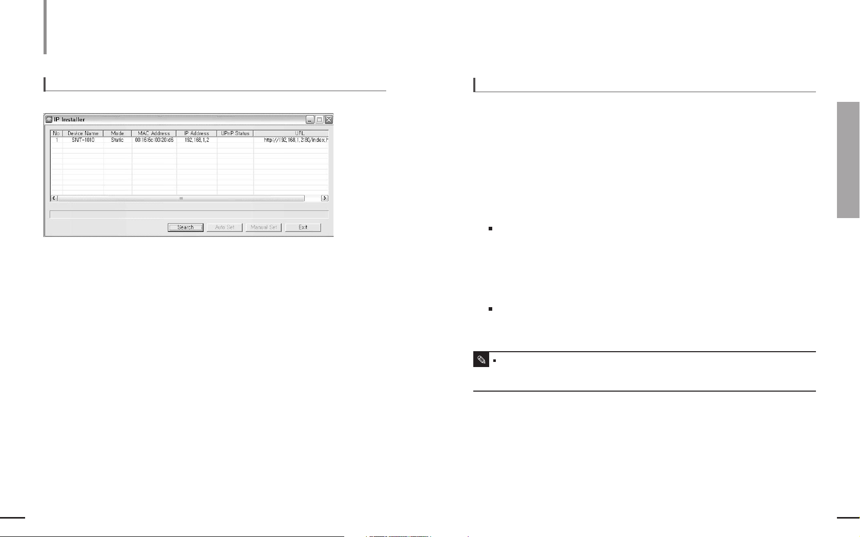
1
<Device Name> : Model name of SNT-1010.
2 <Mode> : Shows the current selection among from <Static>and <Dynamic>.
3 <Mac Address> : The Mac address of the network interface of SNT-1010 that is printed on the rear panel.
4
<IP Address> : The IP address of SNT-1010.(Default setting is '192.168.1.200'.)
5 <UPnP Status> : The SNT-1010 on which the automatic port mapping (port forwarding) is done using UPNP
is marked with <Success>.
6 <URL> : This is an DDNS URL address that can be used to connect from an external Internet.
However, if the DDNS fails to register with your PC, it will be displayed as an IP address of
SNT-1010.
7 [Search ] Button : Searches for SNT-1010 connected to the current network.
8 [Auto Set ] Button : Sets up the SNT-1010 network settings automatically using the <IP Installer>.
9 [Manual Set ] Button : Allows the user to set up the SNT-1010 network settings manually.
10 [Exit ] Button : Exits the IP Installer program.
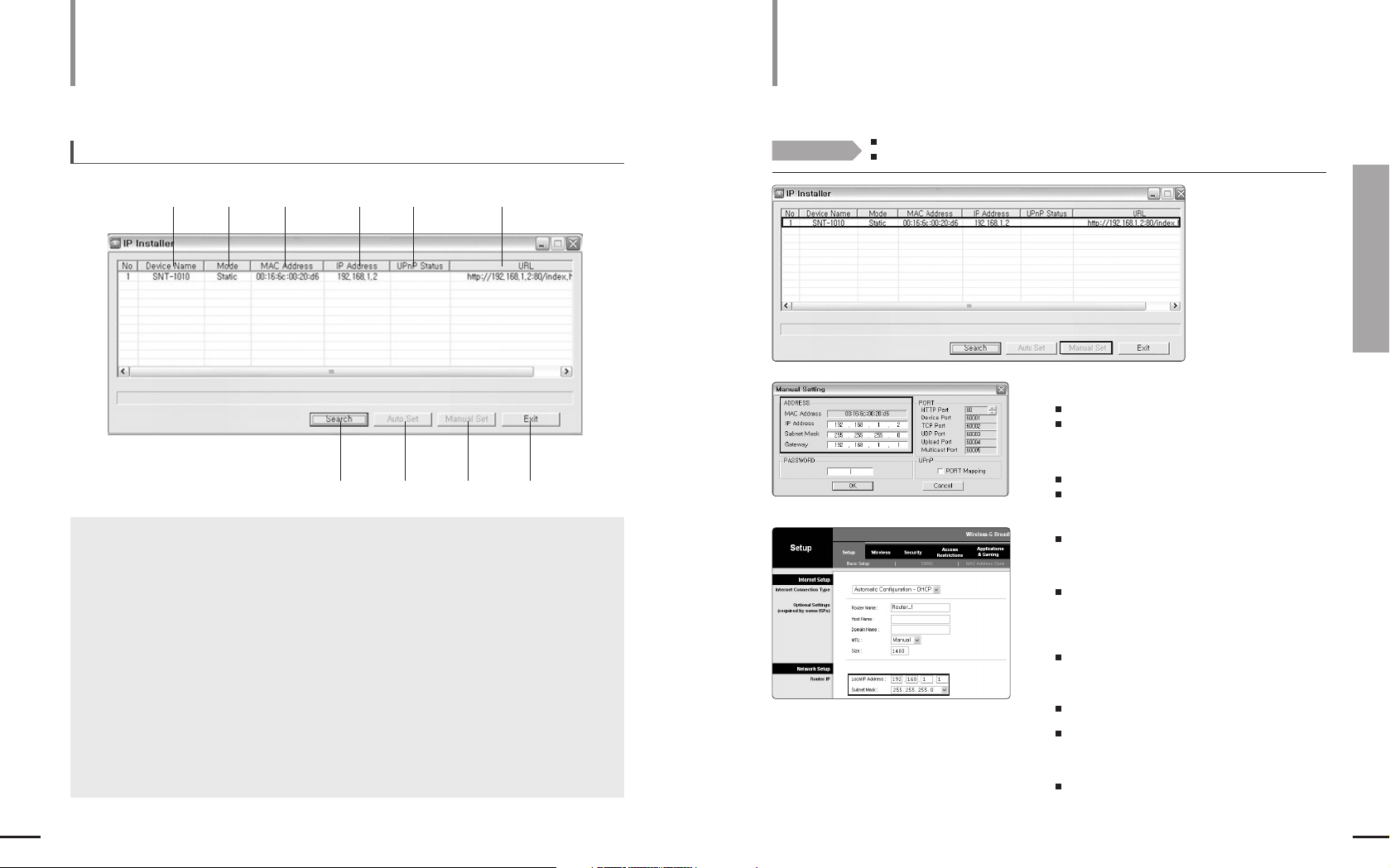
IP Installer screen layout
123 45 6
10987
Static IP Setting
Manual Network Setting
1
Select an SNT-1010 you want from the SNT-1010 list.
Confirm the MAC Address of the SNT-1010 on its rear panel.
The [Auto Set] and [Manual Set] button are activated.
2
Click the [Manual Set] button.
The Manual Set window appears.
The <IP Address>, <Subnet Mask>, <Gateway> and
<HTTP Port> values of the SNT-1010 are displayed in
their default values.
The password is set to 4321 by factory default.
3
Set up the IP related settings in the <ADDRESS>field.
<MAC Address> : The MAC Address printed on the
SNT-1010 rear penal is automatically displayed.
No additional setting is required.
<If using an IP sharer>
<IP Address> : Set it according to the private IP
address range provided by the IP Sharer.
ex) 192.168.1.2~255, 192.168.0.2~255,or
192.168.XXX.2~255
<Subnet Mask> : The IP Sharer’s <Subnet
Mask>becomes SNT- 1010’s <Subnet Mask>value.
<Gateway> : The IP Sharer’s <LAN IP
Address>becomes SNT-1010’s <Gateway>value.
<If not using an IP sharer>
For the <IP Address>, <Gateway> and <Subnet Mask>
settings, contact your network administrator.
Before You Start!
Run the <IP Installer.exe> program and display the found SNT-1010 list on the screen.
For the initial run,the [Auto Set] and [Manual Set] button are all disabled.
1
2
3
3
35
Chapter 4 Static IP Setting
Manual Network Setting
34
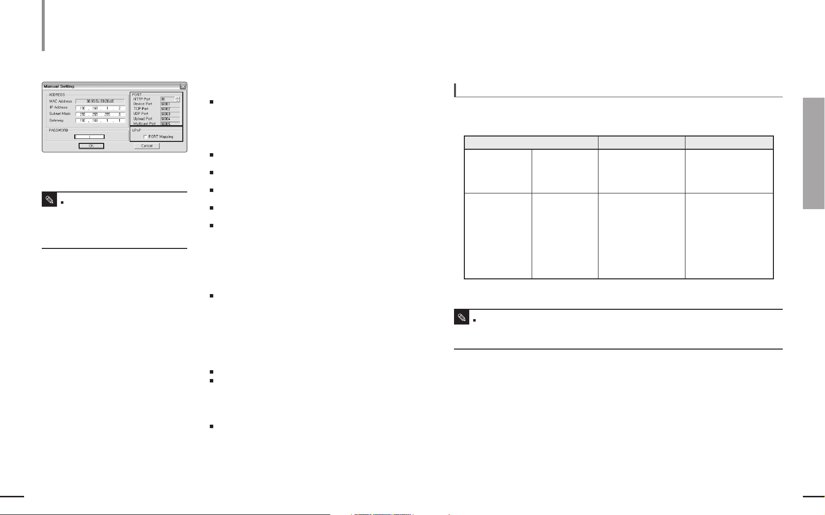
4
In the <PORT>fields,set up port numbers.
<HTTP Port> : A HTTP port used to connect to
SNT-1010 using the Internet browser. The default value
is 80. The HPPT port value can be changed by using
the up/down button to the right. The HTTP port number
starts with 80 and increases/decreases to 10000,
10006, 10012…
<Device Port> : A port used to control video
transmission. The default value is 60001(TCP).
<TCP Port> : A port used to transfer video using TCP
protocol.The default value is 60002(TCP).
<UDP Port> : A port used to transfer video using UDP
protocol.The default value is 60003(UDP).
<Upload Port> : A port used to upgrade software.
The default value is 60004(TCP).
<Multicast Port> : Shows UDP port set for video
transmission using UDP Multicast.
The default value is 60005(UDP).
5
If SNT-1010 is installed on an IP sharer, you can
use the UPNP Port Mapping function.
<PORT Mapping> : If SNT-1010 is installed on an IP
sharer supporting “UPNP Automatic Portmapping (Port
Forwarding)”, the SNT-1010 automatically performs the
port mapping using UPNP when the “Port Mapping”
option is selected.
6
Enter your password.
The default password is 4321.
The password is the SNT-1010 login password of the
root user.
7
Click the [OK] button.
The manual network setting is finished.
8
The SNT-1010 is set to the manually entered
IP and is restarted.
4
5
6
7
If more than one SNT-1010 are connected to an IP Sharer
Manual Network Setting
(Continued)
Static IP Setting
If <HTTP Port>is not set to 80,the user must specify the port number as well as the IP address in the Address
input box of an Internet browser to connect to SNT-1010.
Example) http://IP Address : HTTP Port e.g.http://192.168.1.201: 81
Note
You can’t change the port numbers of
Device, TCP, UDP, Upload and Multicast,
which are automatically changed according
to the increase/decrease of the port number
of HTTP.
Note
set the IP and port Settings for SNT-1010’s differently.
Example)
Items 1st SNT-1010 2st SNT-1010
IP Related Items
PORT Related Items
IP Address
Subnet Mask
Gateway
HTTP Port
Device Port
TCP Port
UDP Port
Upload Port
Multicast Port
192.168.1.200
255.255.255.0
192.168.1.1
80
60001
60002
60003
60004
60005
192.168.1.201
255.255.255.0
192.168.1.1
10000
10001
10002
10003
10004
10005

37
Chapter 5 Dynamic IP Setting
Dynamic IP Setting
36
Static IP Setting
Automatic Network Setting
1
Select an SNT-1010 you want from the SNT-1010 list.
Confirm the MAC Address of the SNT-1010 on its rear panel.
The [Auto Set] and [Manual Set] button are activated.
2
Click the [Auto Set] button.
The Auto Set window appears.
The automatically found <IP Address>,
<Subnet Mask>and <Gate Way> are displayed.
4
Enter your password.
The password is the SNT-1010 login password of
the root user.
The default password is 4321.
5
Click the [OK] button.
The automatic network setting is finished.
6
SNT-1010 automatically restarts when the
network setting is complete.
3
If SNT-1010 is installed on an IP sharer,
you can use the UPNP Port Mapping
function.
Before You Start!
Run the <IP Installer.exe>program and display the found SNT-1010 list on the screen.
In the initial run, the [Auto Set] and [Manual Set] button are all disabled.
2
3
4
1
Dynamic IP Setting
Dynamic IP Setting
Examples of using Dynamic IP
- If SNT-1010 is installed on an IP sharer and obtains an IP using DHCP
- If sNT-1010 is connected directly to a xDSL/Cable modem using DHCP
- If an IP is allocated by the internal DHCP server in local area networking
1.Position the IP selection switch to D (Dynamic IP).
2.Connect SNT-1010 to the IP sharer or modem using the Direct LAN
Cable (UTP cable).
SNT-1010 does not come with the Direct LAN cable.
You have to purchase it separately.
3.Connect SNT-1010 to the power source.
4.When SNT-1010 starts, it automatically obtains an IP address from
the IP sharer or modem.
5.If you use an IP sharer, you can check the dynamic IP address from
the IP sharer by using the IP installer on your PC.
To set SNT-1010 to Dynamic IP mode

39
Chapter 6 When Using an IP Sharer
Port Forwarding (Port Mapping) Setting
When Using an IP Sharer
Port Forwarding (Port Mapping) Setting
With SNT-1010 installed on an IP sharer, you must
set the port forwarding for the IP sharer before an IP
sharer external remote PC can connect to the IP
sharer internal SNT-1010.
Manual Port Forwarding
1
Click <Applications &Gaming> <Port
Range Forward> from the Settings menu
of the IP Sharer.
For the menu location and the setting of Port
Forwarding, refer to the IP sharer’s documentation.
2
Select the <TCP> and <UDP Port> for each
SNT-1010 connected to the IP Sharer.
Each of the port numbers for the IP Sharer must be
according to those presented in <BASIC
CONFIGURATION> <IP>of the SETUP screen
of SNT-1010.
3
If the setting is complete, click the
[Save Settings] button.
The changes are saved.
38
1
2
3
1
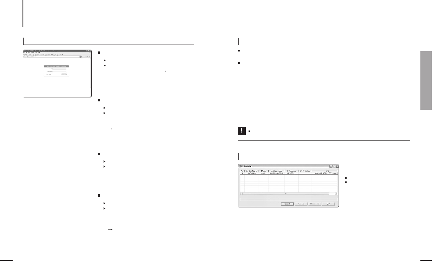
Dynamic IP Check
When you run the IP Installer on your local PC, the SNT-1010 with a dynamic IP
allocated is listed.
Select the SNT-1010 in the list and click the “Manual Set” button to check the
SNT-1010 for the current dynamic IP.
In this case, the ADDRESS field is automatically filled and you can’t change it.
However, you can still change the port and UPNP settings.
Dynamic IP Setting
(Continued)
Dynamic IP Setting
You can use the UPNP Port Mapping function of the IP installer to automatically set
the port forwarding for the IP sharer. However, this is enabled only if the IP sharer
supports the UPNP function.
Automatic Port Forwarding using UPNP
41
Chapter 7 Using SNT-1010
Connecting to SNT-1010
40
Connecting to SNT-1010
(Continued)
To connect to SNT-1010
1
General
Run an Internet browser.
Enter the IP address for SNT-1010 in the Address input box.
Example) IP Address : 192.168.1.200
http://192.168.1.200
- The Login screen appears.
If the HTTP port number is not 80
Run an Internet browser.
Enter the IP address and the HTTP port number for
SNT-1010 in the Address input box.
Example) IP Address : 192.168.1.200:Port Number(8080)
http://192.168.1.200:8080
- The Login screen appears.
Connection using URL
Run an Internet browser.
Enter the DDNS URL for SNT-1010 in the Address input box.
Example) URL Address : http://mff00a0.websamsung.net
- The Login screen appears.
Connection using URL (If the HTTP port number is not 80)
Run an Internet browser.
Enter the DDNS URL and the HTTP port number for
SNT-1010 in the Address input box.
Example)
URL Address : http://mff00a0.websamsung.net:Port Number(8080)
http://mff00a0.websamsung.net:8080
- The Login screen appears.
To check the DDNS address
A DDNS address consists of <One among from lower-case alphabet characters of e,m and p>
+<Last 6 digits of the MAC address>+<websamsung.net>.
The lower-case alphabet letter is represented as <e>if the first 6 digits of the MAC address is
<00:00:f0>, <m> if <00:16:6c>, and <p> if <00:68:36>.
Example) - If the MAC address of SNT-1010 is 00 : 00 : f0 : ff : fe : 42 :
e + fffe42 + websamsung.net = efffe42.websamsung.net
- If the MAC address of SNT-1010 is 00 : 16 : 6c : ff : fe : 42 :
m + fffe42 + websamsung.net = mfffe42.websamsung.net
- If the MAC address of SNT-1010 is 00 : 68 : 36 : ff : fe : 42 :
p + fffe42 + websamsung.net = pfffe42.websamsung.net
The IP and MAC addresses are used in this manual for illustrative purposes only.Therefore,you must not enter
the addresses presented in this manual when you setting your equipment.
Notice
Using SNT-1010
To connect to SNT-1010 using the IP Installer program
Double-click an SNT-1010 you want
from the search result screen.
The Login screen appears.
If the ActiveX window appears, install it
referring to page 43.
43
Chapter 7 Using SNT-1010
Connecting to SNT-1010/Installing ActiveX
For Windows XP Service Pack 2
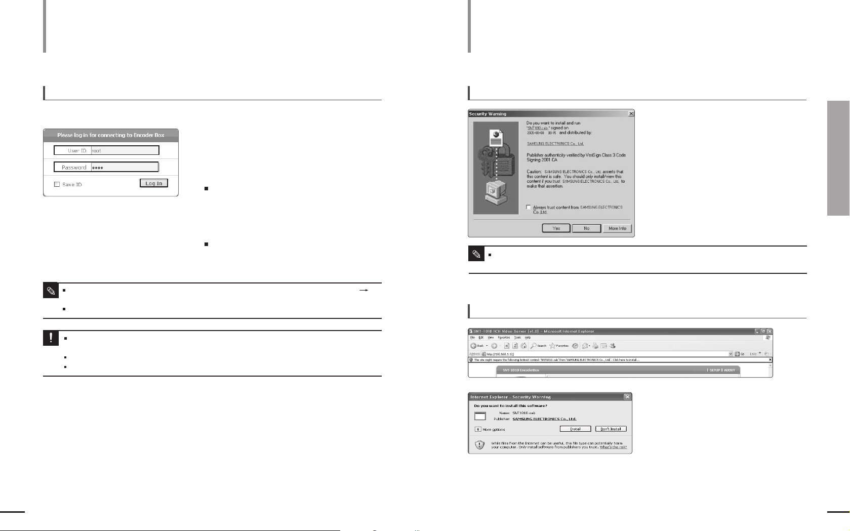
1
If the following screen appears, click the
Install button.
2
Click the <Install ActiveX Control>.
3
If the Security Warning window appears,
click the [Install] button.
42
If you connect the SNT-101 to the Internet and configure the network
settings, you can monitor the picture of the connected camera in real-time.
Using SNT-1010
Installing ActiveX
For Windows 2000/Windows XP
If the Security Warning window appears,
click the Yes button.
1
Type root in the <User ID>input box.
2
Type 4321 in the <Password> input box.
If you have changed the old password, type the new
password here.
3
Click the [Log In] button.
When the
login is complete, the SNT-1010 Viewer
screen appears.
To login
For the first login, the user ID is root and password is 4321.
For the security purposes, make sure to change the password by clicking <BASIC CONFIGURATION>
<USER> in the SETUP screen. The administrator ID, root is fixed and cannot be changed.
I
f you select the <Save ID> check box, the user ID is saved and will be entered automatically in the following logins.
Note
If you have not installed DirectX 8.1 or later on your Windows 2000-based PC and try to log in, you may not
see any video image on the screen.
Note
1
2
3
Using SNT-1010
Connecting to SNT-1010
(Continued)
If you have not installed DirectX 8.1 or later on your Windows 2000-based PC and try to log in, you may not
see any video image on the screen.
You are required to install DirectX 8.1 or later on your Windows-based PC.
You can download DirectX for free at http://www.microsoft.com/download
Notice

45
Chapter 7 Using SNT-1010
Using the Viewer Screen/Viewer Screen Buttons and Functions
Using SNT-1010
Viewer Screen Buttons and Functions
Button Function and Description
Moves to the main screen
You can view information, version, manufacturer, etc.
A logo image set in the <LAYOUT> <SCREEN LOOK> of the SETUP screen appears here.
If a logo link is set, you can open the linked site by clicking it.
The default logo is Samsung Electronics logo.
You can select a screen split option among from the <SINGLE> and <QUAD>.
<SINGLE>: Displays the video in its original size.
<QUAD> : Splits the screen into 4 and displays 4 videos on the screen.
In the <QUAD> mode, the < > mode is not supported.
SNT-1010 provides Dual Codec function so that it can apply 2 codecs to a video source
simultaneously and transmit it.
You can change the setting in the <BASIC CONFIGURATION> <VIDEO> of the SETUP
screen. Page 50
If you check the <De-Interlace> option,you can enjoy a clearer image on the screen.
If you deselect <De-Interace>,the still image can be a bit clearer but the moving image may
be cracked or overlapped on the border of an object.
Shows the current video codec information among from <MJPEG> and <MPEG4>.
Moves to the SETUP screen.
You can select a screen size from the < >, < >, < > and < >.
< > : Displays the video in its original size.
< > : Zooms-out the video size to its 1/4 and displays it in the center.
< > :
Displays the video fitting to the viewer screen size. The aspect ratio of the video may be different.
< > : You can see the image in full screen. To exit the mode, press the ESC key on the keyboard.
The video display returns to its previous size.
Lists connected SNT-1010’s. If you select an SNT-1010, the corresponding video appears.
On the first row, the login SNT-1010 appears.
From the second row on, additionally connected SNT-1010’s are displayed.
You can additionally register an SNT-1010 in <BASIC CONFIGURATION> <EXTERNAL SNT-1010>
of the SETUP screen.
The selected SNT-1010 is indicated by inversed font color.
The viewer screen will appear according to the video size set in the <BASIC CONFIGURATION> <VIDEO> of the SETUP screen.
<D1>: 720 x 480(NTSC), 720 x 576 (PAL) <CIF>: 360 x 240(NTSC), 360 x 288 (PAL)
<VGA>: 640 x 480 <QCIF>: 176 x 112(NTSC), 176 x 144 (PAL)
Note
44
Using SNT-1010
Using the Viewer Screen
If you connect to an SNT-1010, the following
Viewer screen appears.
Main Screen Layout
1 Version Information:The
version number of the installed
Viewer ActiveX Control.
2 VIEWER Tab
3 SETUP Tab
4 ABOUT Tab
5 Logo
6 Video Format
7 Video Source
8 De-Interlace
9 Screen Size & Partition Buttons
[ ] [ ] [ ] [ ]
Buttons
[SINGLE] [QUAD] Buttons
10 SNT-1010 List
11 Continuous View Button
12 Sequential View Button
13 CAPTURE Button
14 RECORD Button
15 Play Control Buttons [OPEN]
[PLAY] [PAUSE] [STOP]
Buttons
16 Audio Buttons [LISTEN]
[SPEAK] [VOL ] Button
17 Banner Image
18 Direction Buttons
19 ENTER Button
20 MENU Button
21 PRESET Button
22 ZOOM IN Button
23 AUTOPAN Button
24 ZOOM OUT Button
25 Focus Near Button
26 SCAN Button
27 Focus Far Button
28 PATTERN Button
29 ALARM RESET Button
30 Viewer Screen
1
2
17
18 21
23
26
19 20
34
5
8
14
12
6
9
10
13
15
16
11
7
22 2825 27 2924
30

47
Chapter 7 Using SNT-1010
Viewer Screen Buttons and Functions
46
Viewer Screen Buttons and Functions
(Continued)
Using SNT-1010
To Capture a Video
1
At a desired scene, click the [CAPTURE] button.
The capture confirmation window appears.
2
Click [OK].
The captured screen image is saved in the specified folder path.
The default saving path is “C:WProgram FilesWSamsungWSNT-1010WSnapShot”.
To change the saving path, click <BASIC CONFIGURATION> <LOCAL SAVE PATH> in the SETUP screen.
The file is automatically named as follows: “YYMMDD_HHMMSS_device name_EncoderID.extension”.
Example) 20060207_121015_SNT-1010_EncoderBox.jpg
Capturing a screen is available even during a recording. In this case, the <Overlay> is also captured together.
Note
To Record a Video
1
At desired scene, click the [RECORD] button.
On the viewer screen, <REC> indicator appears and the
recording is started.
REC
2
To stop a recording, click the [RECORD] button once again.
The captured screen image is saved in the specified
saving path.
The default saving path is “C : WProgram FilesWSamsungWSNT-1010WVideoClip”.
To change the saving path, click <BASIC CONFIGURATION> <LOCAL SAVE PATH> in the SETUP screen.
The file is automatically named as follows: “YYMMDD_HHMMSS_device name_EncoderID. extension”.
Example) 20060207_121015_SNT-1010_EncoderBox.cam
The maximum recording time is 10 minutes.If a recording exceeds the time limit, the recording is automatically
terminated and the announcement message appears.
The user can select and record a camera video and stop it.
Note
Button Function and Description
Saves the current video as a .cam video file. Page 47
You can use camera functions such as lens
direction control, menu setting, preset, etc.
Page 48
Captures the current picture on the screen and saves it as a .jpg or .bmp image file.
Page 47
You can Open/Play/Pause/Stop a saved file.
If the file size is big, the loading time might be long
If you click the [LISTEN] button, the speaker icon appears on the screen and you can hear the audio from the current video source.
If you click the [SPEAK] button, you can transmit your voice to the SNT-1010 using a microphone.
If multiple users are connected to an SNT-1010, only one user can send his voice at a time.
You can control the volume of the current video by using the [VOL ] buttons in 10 steps.
A banner image set in the <LAYOUT> <SCREEN LOOK> of the SETUP screen appears here.
If a banner link is set, you can open the linked site by clicking it.
Initially, no banner image is set.
This function is available when multiple SNT-1010’s are connected.
Each video channel of the connected SNT-1010’s is displayed sequentially.
This function is not available while playing a recorded file.
If the screen size is <SINGLE>, this function is available only when more than 1 SNT-1010 are in the <SNT-1010 List>.
If the screen size is <QUAD>, this function is available only when more than 4 SNT-1010 are in the <SNT-1010 List>
If the screen size is <SINGLE>, each video channel is displayed by turns.
If the screen size is <QUAD>, 4 videos channels are displayed by turns.

49
Chapter 8 Setting Up
Setting SNT-1010
48
Setting Up
Viewer Screen Buttons and Functions (Continued)
Using SNT-1010
Setting SNT-1010
You can set various functions such as Basic Setting, System,
Layout, etc.
In the viewer screen, click the [SETUP] tab.
The SETUP screen appears.
To use the camera related functions
These functions are activated only if they are supported by the camera and are the same as the camera settings.
Power Pan and Tilt Function
This function works only in a camera supporting the power pan-and-tilt. Ex) Samsung SCC-6475
If you click over a point you want, this function moves the camera so that the point comes to the center of the screen.
If you drag the mouse downward while holding down the left mouse button, the video is zoomed in while you drag the mouse upward, the screen is zoomed out.
SETUP Screen Layout
SETUP Screen
VIDEO
IP
USER
EXTERNAL SNT-1010
LOCAL SAVE PATH
LANGUAGE
DATE/TIME
STATUS
LOG
S/W UPDATE
RESET
RS485
OVERLAY IMAGE
OVERLAY TEXT
SCREEN LOOK
VIEW HTML
TRANSFER SETUP
ALARM IMAGE
ALARM INPUT1
ALARM INPUT2
ALARM INPUT3
ALARM INPUT4
MOTION DETECTION
VIDEO LOSS
SCHEDULE TRANSFER
STREAMING SETUP
BASIC CONFIGURATION
SYSTEM LAYOUT EVENT NETWORK
IP NOTIFICATION
DDNS
Moving lens direction and selecting a menu
- You can adjust the camera lens direction using the 8 direction buttons.
While you are pressing the button, the camera moves and if you release the button, the camera stops.
- buttons are used to navigate through the menu in the camera menu screen.
- [ENTER] button is used to select a menu item in the camera menu screen.
Entering Camera Menu
- The camera menu screen appears.
Zoom Function
- Click the [ZOOM IN] button to zoom-in.
- Click the [ZOOM OUT] button to zoom-out.
Focus Function
- Press the [Focus Near] button to adjust the focus nearer.
- Press the [Focus Far] button to adjust the focus farther.
Preset Function
- Moves the lens direction to a preset direction.
Autopan Function
- Moves the camera lens direction between 2 points set for the camera.
Scan Function
- Moves the camera lens direction between 2 preset points of the camera.
Alarm Reset Function
- Returns the current alarm settings to the default.
Pattern Function
- You can set camera various movement patterns such as zoom, move, etc. so that a
camera automatically moves according to the pattern.
The Focus function is available only in Manual Focus mode.
The Power Pan & Tilt function can make angular difference, depending on the zooming level of the camera.
Notice

51
Chapter 8 Setting Up
Basic Configuration
50
<IP Type> : Shows the current SNT-1010 IP setting type.
- To change the IP setting type, slide the [IP select switch] on the front panel to <D> or <S> position according to your needs.
<IP Configuration> : Allows setting SNT-1010 IP and port related settings.
- <MAC Address> : Shows the Ethernet MAC address. Since this value is used to create a DDNS address, confirm the value.
- <IP Address> : Shows the currently configured IP address. If the <IP Type> is set to <Static IP>, you can change the IP address.
- <Subnet Mask> : Shows the <Subnet Mask> for the configured IP address.
- <Gateway> : Shows the <Gateway> address for the configured IP address.
- <DNS Server> : Shows the IP address of the DNS (Domain Name Service) server.
-
<HTTP Webserver Port> : Shows the HTTP port used to connect to the SNT-1010 using the web browser.The default port number is 80(TCP).
- <Device Port(TCP)> : A port used to control video transmission. The default value is 60001(TCP).
- <TCP Streaming Port> : A port used to transfer video using the TCP protocols. The default value is 60002(TCP).
- <UDP Streaming Port> : A port used to transfer video using the UDP multicast protocols. The default value is 60003(UDP).
- <Upload Port(TCP)> : A port used to upgrade software. Default value is 60004(TCP).
<Multicast Settings> : To transmit a video using UDP Multicast, you can set the IP address, port and TTL.
- <Multicast Address> : Shows IP address set for video transmission using UDP Multicast.
The default value is 239.0.0.1. It is recommended to set it to between 224.0.0.0 and 239.255.255.255.
- <Multicast Port> : Shows UDP port set for video transmission using UDP Multicast. The default value is 60005(UDP).
- <TTL> : TTL stands for “Time To Live” that allows you to set the number of routers so that the packet can pass through.
Each router decrease the TTL value one by one when a packet passes it through. If the TTL value reaches 0, the packet cannot pass
through a router. The default value is 63. It is recommended to set it to between 0 and 255.
To setup IP settings
If more than an SNT-1010 are
connected to an IP Sharer, set the IP
and port Settings for SNT-1010’s
differently. 35 Page
Note
You can set the video format, size, resolution, frames per second for <Video1> and <Video2>.
<Video Format> : Select a video format from <MPEG4> and <MJPEG>.
- To transmit a video when an event occurs, either <Video1> or <Video2> must be set to <MJPEG>.
- To use the motion detection function, either <Video1> or <Video2> must be set to <MPEG4>.
Example) To set <Video1> for the motion detection and to send a video from <Video2> to an e-mail or FTP when an
event occurs, set the <Video1> to <MPEG4> and the <Video2> to <MJPEG>.
<Resolution> : Select a video size among from <D1>, <VGA>, <CIF> and <QCIF>.
- <D1>: 720 x 480 (NTSC), 720 x 576 (PAL)
- <VGA> : 640 x 480
- <CIF> : 360 x 240(NTSC), 360 x 288 (PAL)
- <QCIF> : 176 x 112(NTSC), 176 x 144 (PAL)
<Quality>: Select a resolution from <Very High>, <High>, <Normal>, <Low> and <Very Low>.
<Frame Rate(Max)> : Shows the maximum number of frames per second depending on the
Bandwidth configured in <NETWORK> <STREAMING SETUP>
<Streaming Control>. If it is set to <Unlimited>, you can select one from
<30 fps>, <15 fps>, <7.5 fps>, <3 fps> and <1 fps>.
Click <BASIC CONFIGURATION>
<VIDEO>.
The VIDEO CONFIGURATION window
appears.
Setting Video
To complete the video setting,
click the [Apply] button.
The settings are saved.
Click <BASIC CONFIGURATION>
<IP>.
IP Setting window appears.
To complete the setting, click the
[Apply] button.
The settings are saved and the system is restarted.
The currently opened web browser is closed.
Basic Configuration
Setting Up
53
Chapter 8 Setting Up
Basic Configuration
52
Setting Up
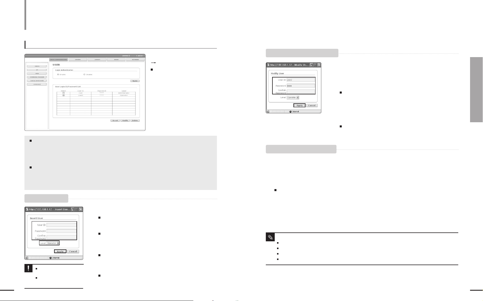
1
In the USER window, click the [Insert] button.
The <Insert User> window appears.
2
Enter user ID and password.
For the ID and password, up to 19 alphanumeric and some special
characters are allowed.
3
Select the user permission.
Select a user permission for the new user from the <Operator> and <User>
in the Level field.
4
Click the [Apply] button.
The user registration is completed.
You cannot register a
duplicated user ID.
You can register root or guest
user ID.
Notice!
To register a user
To modify a registered user account
To delete a registered user account
Basic Configuration
(Continued)
<Login Authentication> : You can determine whether to require login authentication for users.
-
If it is set to <Enable>, the users can connect to the system through login authentication, while it is set to <Disable>, the users can
connect to the system without login authentication. However, users connected to the system without login have USER permission.
- When the setting is complete, click the [Apply] button.
<User Login ID/Password List> : Shows user ID, password and level (permissions) in a list.
- You can register up to 10 users.
- <Administrator> cannot be deleted or added. In addition, the default administrator ID is root and you can change the
password only.
To setup users
Click <BASIC CONFIGURATION>
<USER>.
The USER window appears.
1
Select the <Select> check box of a user account to be modified in
the USER window.
2
Click the [Modify] button in the USER window.
The <Modify User> window appears.
3
In the window, modify ID, password or user level of the user
account.
1
Select the <Select> check box of a user account to be deleted in the USER window.
2
Click the [Delete] button in the USER window.
Deleting a registered user is complete.
4
Click the [Apply] button.
Modifying a registered user is complete.
About User Level
Administrator : The Administrator can use all functions and change the settings.
Operator : The Operator can use all functions except setting functions.
User : The User can monitor video only.
Guest : The guest can login by typing guest for both ID and password and can use simple monitoring function only.
Note
2
3
4
3
4
55
Chapter 8 Setting Up
Basic Configuration
54
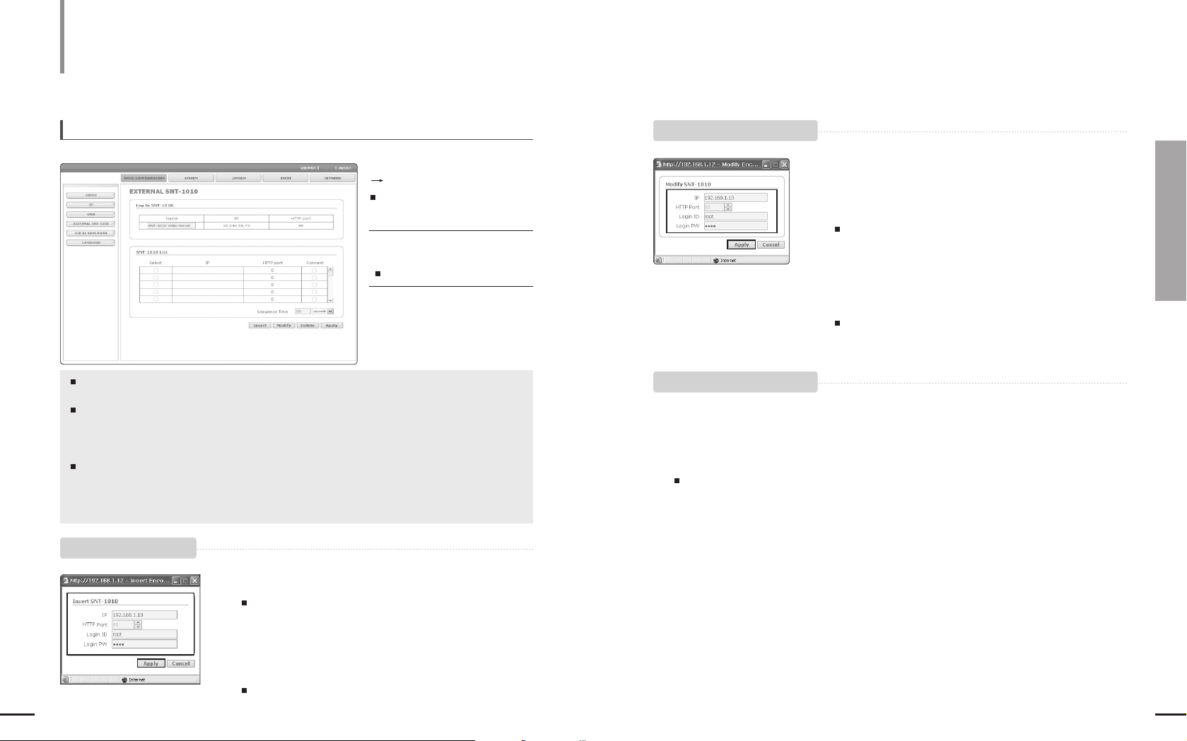
To setup an external SNT-1010
<Log In SNT-1010> : Shows the Name, IP and HTTP Port of the currently logged-in
SNT-1010. You can change the SNT-1010 name.
<SNT-1010 List> : Shows the list of external SNT-1010’s added by the user. You can add up
to 30 external SNT-1010. If you select the <Connect> check box, the
selected SNT-1010 is connected and appears in the SNT-1010 list in the
VIEWER screen.
<Sequence Time> : Determines the screen transition time when the [SEQUENCE] button in
the View screen is pressed. If you select <seconds> in the combo box,
you can set the time from 10 to 3540 seconds. If you select <minutes>,
you can set the time from 1 to 59 minutes.
Setting Up
Basic Configuration
(Continued)
Click <BASIC CONFIGURATION>
<EXTERNAL SNT-1010>.
The EXTERNAL SNT-1010 window
appears.
To complete the setting, click the
[Apply] button.
The settings are saved.
1
2
3
In the EXTERNAL SNT-1010 window, click the [Insert] button.
The <Insert SNT-1010> window appears.
2
Enter the IP, HTTP Port, Login ID, Login PW for the SNT-1010.
3
Click the [Apply] button.
SNT-1010 registration is complete.
1
Select the <Select> check box of an SNT-1010 to be modified in the
EXTERNAL SNT-1010 window.
2
In the EXTERNAL SNT-1010 window, click the [Modify] button.
The <Modify SNT-1010> window appears.
3
Modify the IP, HTTP Port, Login ID or Login PW.
1
Select the <Select> check box of an SNT-1010 to be deleted in the EXTERNAL SNT-1010 window.
2
In the EXTERNAL SNT-1010 window, click the [Delete] button.
Deleting a registered SNT-1010 is complete.
4
Click [Apply].
Modifying a registered SNT-1010 is complete.
3
4
To register an SNT-1010
To modify a registered SNT-1010
To delete a registered SNT-1010
57
Chapter 8 Setting Up
Basic Configuration/System Configuration
56
Setting Up
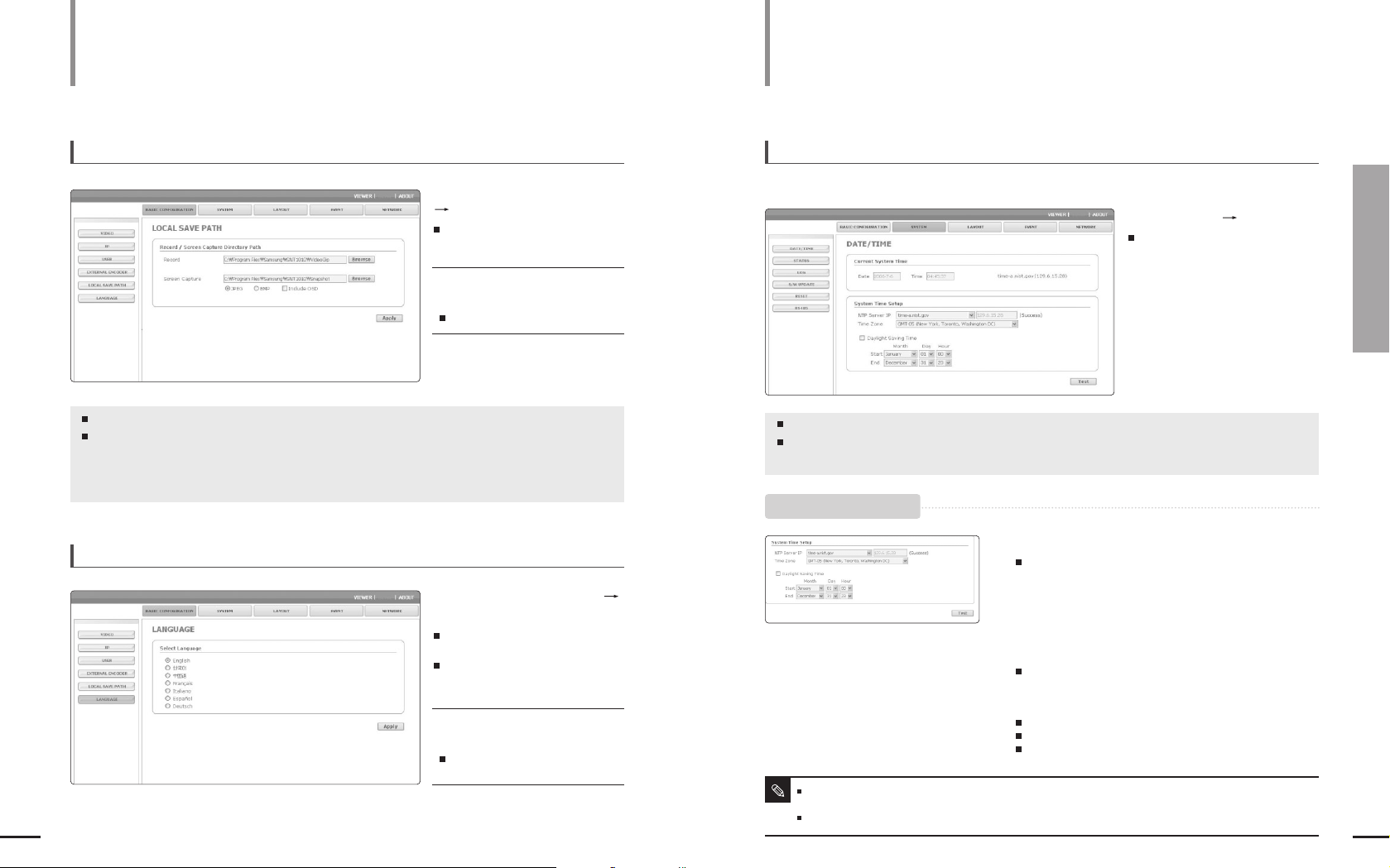
To set the record/capture saving path
<Record> : Determines the saving path of the recorded file.
<Screen Capture> : Determines the capture file saving path. You can select either <JPEG>
or <BMP> file format to save a captured file. If you select the <Include
OSD> check box, the screen is captured including on-screen
information including image, text, date, time.
Basic Configuration (Continued)
Click <BASIC CONFIGURATION>
<LOCAL SAVE PATH>.
The LOCAL SAVE PATH window
appears.
To complete the setting, click the
[Apply] button.
The settings are saved.
To set the display language
Click <BASIC CONFIGURATION>
<LANGUAGE>.
The LANGUAGE window appears where
you can select a preferred language.
You can select once from 7 languages
(English/Korean/Chinese/French/Italian/
Spanish/German).
To complete the setting, click the
[Apply] button.
The language has been changed to
the selected one.
Setting Up
System Configuration
To setup date and time
You can get the current system time from a NTP server and set the system time.
<Current System Time> : Sets the time by synchronizing with the selected NTP server (time server).
<System Time Setup> : You can select a preferred NTP server address, time zone, and
whether to apply daylight saving time.
The servers listed in the <NTP Server IP> are provided by a public institution and the list may be changed.
The <Manual> option allows selecting a time server provided by a private institution.
If you are using a local network that is not connected to the Internet, NTP server cannot be connected.
Note
Click <SYSTEM> <DATE/TIME>.
The Date/Time window appears.
1
Select one of the NTP server addresses of the <NTP Server IP> list.
If you select <Manual>, you can enter the IP address in the right
input box manually.
2
Select your time zone in the <Time Zone> filed.
3
To apply daylight saving time, select the <Daylight Saving
Time> checkbox.
You can change the Start and End Date for daylight saving time.
4
Click the [Test] button.
The configured system time is applied.
The IP address of the set NTP server is displayed.
If the setting is succeeded, the <Success> message will appear.
Otherwise, <Fail> message will appear.
To setup the system time

59
Chapter 8 Setting Up
System Configuration
58
Setting Up
To view the log information
The log information is initialized when an
SNT-1010 is restarted.
The log information is displayed only when
the system time is set.
Note
System Configuration
(Continued)
To check the connection status
Click <SYSTEM> <STATUS>.
The Status window appears showing
the connection status.
Click <SYSTEM> <S/W UPDATE>.
The Software Update window appears.
Click <SYSTEM> <LOG>.
The Log window appears showing log
information.
<Current Status> : Shows the number of users connected to the current system and the IP addresses
of them. The connection status is updated every 5 seconds.
<System Log List> : Shows the log information about the system changes along with time and IP address.
-
<User Log In>: Shows current SNT-1010 login user.
-
<Video Configuration Change> : Shows video setting changes.
-
<System Time Change> : Shows time changes.
-
<System Start> : Shows time when the SNT-1010 is turned on.
To update the software
To download the latest version of the software, visit Samsung Electronics web site
www.samsung.com.
The update files are named such as SNT-1010-V1.1-20060531.tgz.
Software update supports update files that has predetermined file names.
Do not change the file name except the date (20060531).
Since, if the network is disconnected, the power fails or the PC abnormally operates during a software update, the system may
not work afterwards, take care not to cause a problem during an update.
Notice
1
In the USER window, click the [Browse] button.
The Open File window appears.
2
Select an SNT-1010 update file and click the [Open] button.
3
In the USER window, click the [Install] button.
The file is uncompressed and the software update begins.
Software update may take tens of minutes.
To cancel an update, click the [Cancel] button.
4
When the software update is done, the system will
automatically restart.
Since the current connection is disconnected, you have to connect
to the system again.
To update the software
 Loading...