

Samsung DSR9400VIA Service manual
DIGITAL SATELLITE RECEIVER
DSR9400 FTA
DSR9400 EM VIA
SERVICE
1. Precautions
2. Operating Instructions
3. Software Upgrade and Installation
4. Troubleshooting
5. Exploded View and Parts List
6. Electrical Parts List
7. PCB Diagrams
8. Schematic Diagrams
Manual
DIGITAL SATELLITE RECEIVER CONTENTS
SERVICE MANUAL
DSR9400 (FTA, EM VIA)
ELECTRONICS
© Samsung Electronics Co., Ltd. NOV. 2002
Printed in Korea
MF82-00009A
Samsung Electronics 1-1
1. Precautions
1. Be sure that all of the built-in protective devices are
replaced. Restore any missing protective shields.
2. When reinstalling the chassis and its assemblies, be
sure to restore all protective devices, including :
control knobs and compartment covers.
3. Make sure that there are no cabinet openings
through which people--particularly children
--might insert fingers and contact dangerous
voltages. Such openings include the spacing
between the picture tube and the cabinet mask,
excessively wide cabinet ventilation slots, and
improperly fitted back covers.
If the measured resistance is less than 1.0 megohm
or greater than 5.2 megohms, an abnormality exists
that must be corrected before the unit is returned
to the customer.
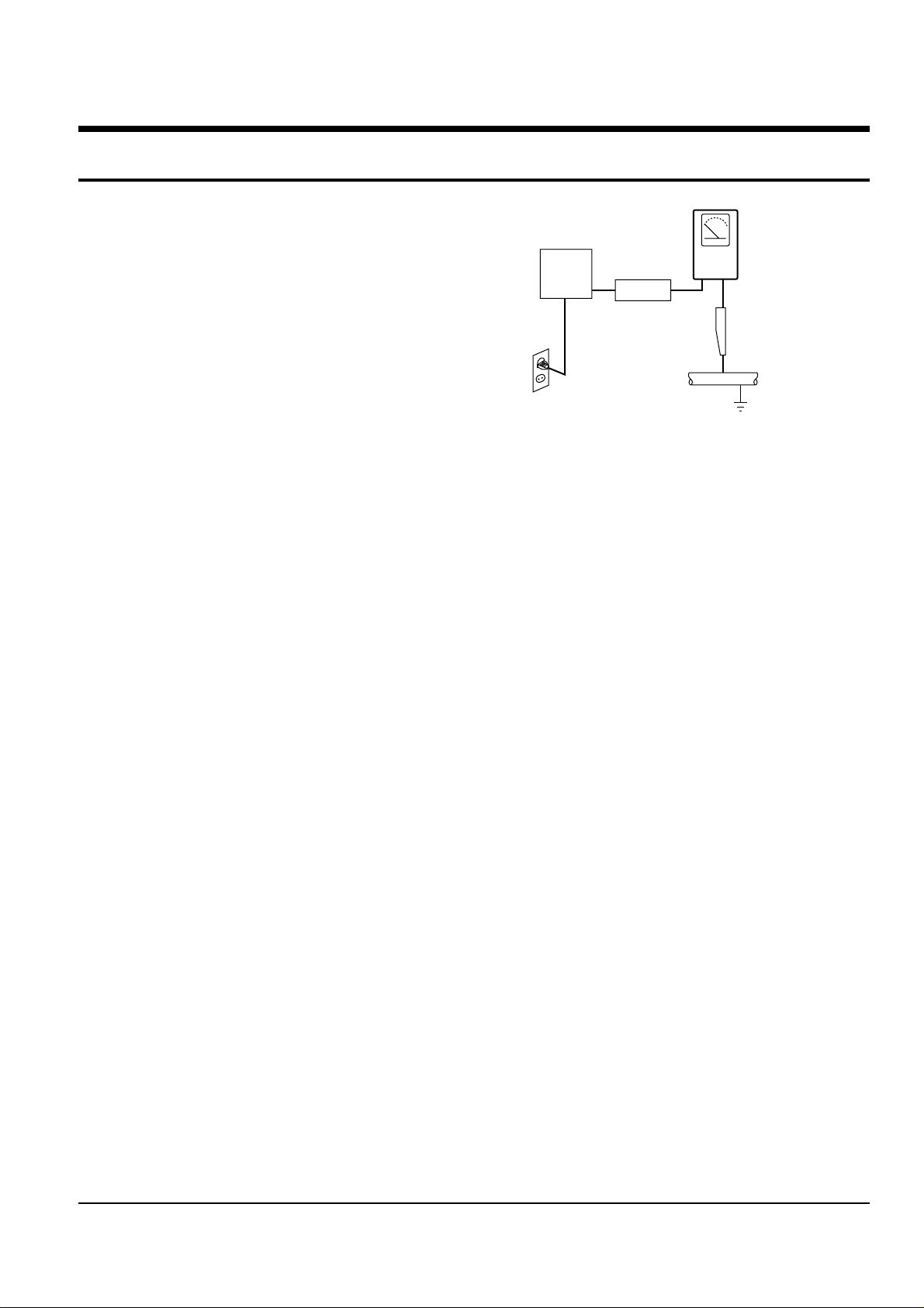
4. Leakage Current Hot Check (See Fig. 1-1) :
Warning : Do not use an isolation transformer
during this test. Use a leakage current tester or a
metering system that complies with American
National Standards Institute (ANSI C101.1,
Leakage Current for Appliances), and Underwriters
Laboratories (UL Publication UL1410, 59.7).
5. With the unit completely reassembled, plug the AC
line cord directly the power outlet. With the unit’s
AC switch first in the ON position and then OFF,
measure the current between a known earth
ground (metal water pipe, conduit, etc.) and all
exposed metal parts, including : antennas, handle
brackets, metal cabinets, screwheads and control
shafts. The current measured should not exceed
0.5 milliamp. Reverse the power-plug prongs in the
AC outlet and repeat the test.
6. X-ray Limits :
The picture tube is designed to prohibit X-ray
emissions. To ensure continued X-ray protection,
replace the picture tube only with one that is the
same type as the original.
Fig. 1-1 AC Leakage Test
7. Antenna Cold Check :
With the unit’s AC plug disconnected from the
AC source, connect an electrical jumper across the
two AC prongs. Connect one lead of the ohmmeter
to an AC prong.
Connect the other lead to the coaxial connector.
8. High Voltage Limit :
High voltage must be measured each time
servicing is done on the B+, horizontal deflection
or high voltage circuits.
Heed the high voltage limits. These include the
X-ray protection Specifications Label, and the
Product Safety and X-ray Warning Note on the
service data schematic.
9. Some semiconductor (“solid state”) devices are
easily damaged by static electricity.
Such components are called Electrostatically
Sensitive Devices (ESDs); examples include
integrated circuits and some field-effect transistors.
The following techniques will reduce the
occurrence of component damage caused by static
electricity.
10. Immediately before handling any semiconductor
components or assemblies, drain the electrostatic
charge from your body by touching a known
earth ground. Alternatively, wear a discharging
Wrist-strap device. (Be sure to remove it prior to
applying power--this is an electric shock
precaution.)
DEVICE
UNDER
TEST
(READING SHOULD
NOT BE ABOVE
0.5mA)
LEAKAGE
CURRENT
TESTER
EARTH
GROUND
TEST ALL
EXPOSED METER
SURFACES
ALSO TEST WITH
PLUG REVERSED
(USING AC ADAPTER
PLUG AS REQUIRED)
2-WIRE CORD

Precautions
1-2 Samsung Electronics
11. High voltage is maintained within specified limits
by close-tolerance, safety-related components and
adjustments. If the high voltage exceeds the
specified limits, check each of the special
components.
12. Design Alteration Warning :
Never alter or add to the mechanical or electrical
design of this unit. Example : Do not add
auxiliary audio or video connectors.
Such alterations might create a safety hazard.
Also, any design changes or additions will void
the manufacturer’s warranty.
13. Hot Chassis Warning :
Some TV receiver chassis are electrically
connected directly to one conductor of the AC
power cord. If an isolation transformer is not
used, these units may be safely serviced only if
the AC power plug is inserted so that the chassis
is connected to the ground side of the AC source.
To confirm that the AC power plug is inserted
correctly, do the following : Using an AC
voltmeter, measure the voltage between the
chassis and a known earth ground. If the reading
is greater than 1.0V, remove the AC power plug,
reverse its polarity and reinsert. Re-measure the
voltage between the chassis and ground.
14. Some TV chassis are designed to operate with 85
volts AC between chassis and ground, regardless
of the AC plug polarity. These units can be safely
serviced only if an isolation transformer inserted
between the receiver and the power source.
15. Never defeat any of the B+ voltage interlocks.
Do not apply AC power to the unit (or any of its
assemblies) unless all solid-state heat sinks are
correctly installed.
16. Always connect a test instrument’s ground lead to
the instrument chassis ground before connecting
the positive lead; always remove the instrument’s
ground lead last.
17. Observe the original lead dress, especially near
the following areas : Antenna wiring, sharp
edges, and especially the AC and high voltage
power supplies. Always inspect for pinched, outof-place, or frayed wiring. Do not change the
spacing between components and the printed
circuit board. Check the AC power cord for
damage. Make sure that leads and components
do not touch thermally hot parts.
18. Picture Tube Implosion Warning :
The picture tube in this receiver employs
“integral implosion” protection. To ensure
continued implosion protection, make sure that
the replacement picture tube is the same as the
original.
19. Do not remove, install or handle the picture tube
without first putting on shatterproof goggles
equipped with side shields. Never handle the
picture tube by its neck. Some “in-line” picture
tubes are equipped with a permanently attached
deflection yoke; do not try to remove such
“permanently attached” yokes from the picture
tube.
20. Product Safety Notice :
Some electrical and mechanical parts have special
safety-related characteristics which might not be
obvious from visual inspection. These safety
features and the protection they give might be
lost if the replacement component differs from the
original--even if the replacement is rated for
higher voltage, wattage, etc.
Components that are critical for safety are
indicated in the circuit diagram by shading,
( or ).
Use replacement components that have the same
ratings, especially for flame resistance and
dielectric strength specifications. Areplacement
part that does not have the same safety
characteristics as the original might create shock,
fire or other hazards.

Samsung Electronics 3-1
3. Software Upgrade and Installation
3-1 Flash Memory Writing process
How to input software after changing Boot software and replacing Flash Memory.
3-1-1 JPI Setting Manual
1) JPI exe Program : Setting ver R1.80
Make C:\STM\ST20R1.80 folder in C and copy exe file.
Execute setup file in C:\STM\ST20R1.80 folder.
2) PC Setting
Execute vppi set in bin folder, opening C:\STM\ST20R1.80\bin folder
Port type in vppi set up : Auto Detect -> EPP
Access Mode : after altering Synchronous -> Interrupt,
Click Apply and close “vppi set up”.
Open Regedit exe in Windows (O) : regedit
HKEY_LOCAL_MACHINE double click -> SYSTEM double click -> CURRENT CONTROL SET double
click -> SERVICES double click -> VxD double click
vppi set click -> *Access Mode : 0x00000002(2)
*Port Type : 0x00000003(3)
◆ Following line should be added at Autoexec.bat of PC.
SET ST20ROOT=C:\STM\ST20R1.80
SET STVM_HOME=C:\STM\ST20R1.80
SET TOOLSET=C:\STM\ST20R1.80
3) Caution
◆ When Defaulting in vppi set up (in case of not altering)
Access Mode : 0x00000003(3)
◆ Port Type : 0x00000000(0)
◆ When inputting boot program as JPI, following items should be
omitted in C:\windows\system.ini file[386Enh].
device=C:\ST20SWC\tools\vwrun.386
device=C:\ST20SWC\tools\vb045st.386
device=C:\ST20SWC\tools\vb008st.386
* If copied by PPI, above items should be included.
Software Upgrade and Installation
3-2 Samsung Electronics
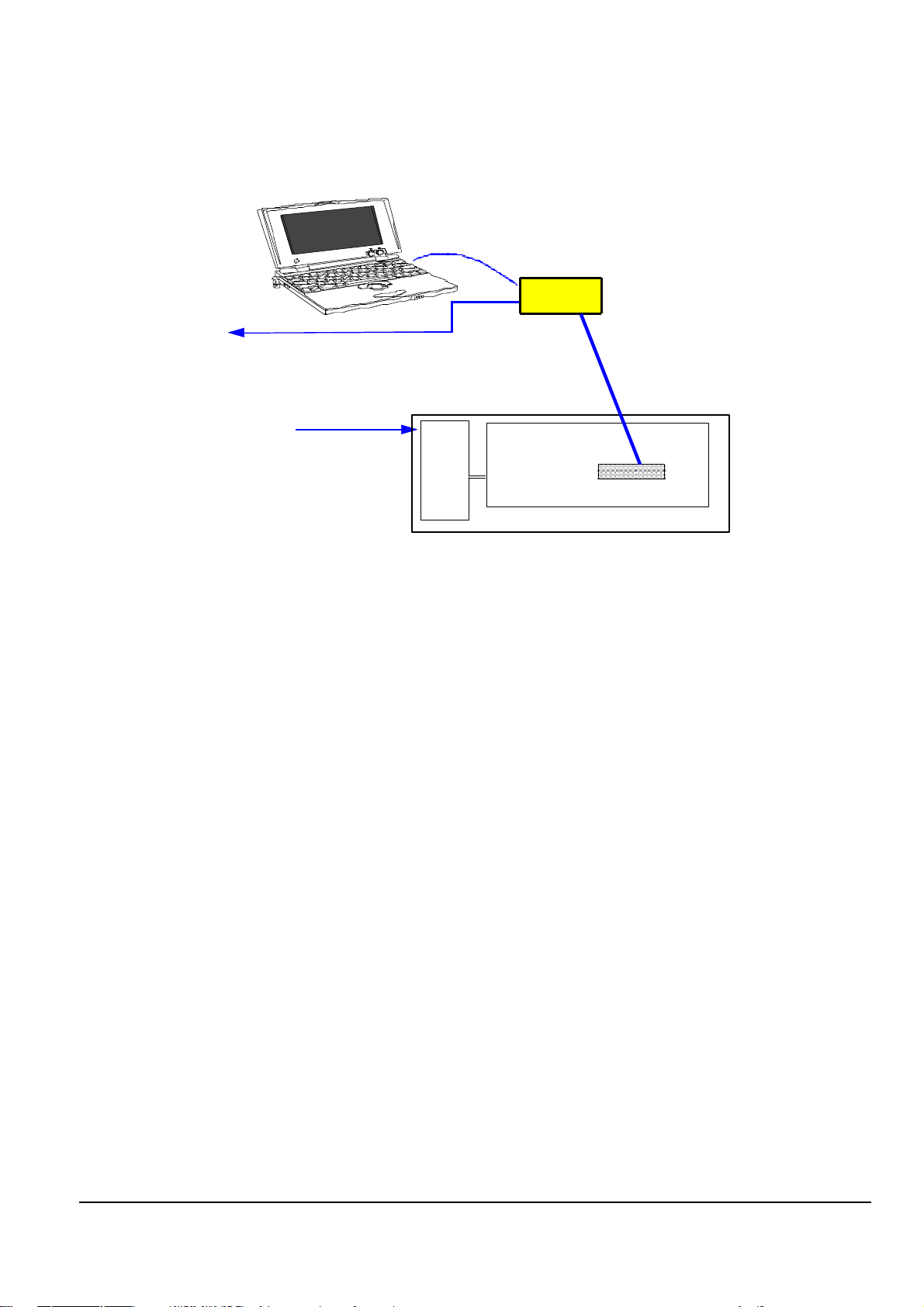
3-1-2 Boot Software Input Process (Same Process in Main Software Installing)
<How to install software using JPI Adapter>
ΠPrepare PC and JPI, DSR 9400 as above figure.
´ Connect MAIN BOARD to JIG, JPI ADAPETER to JPI Port of MAIN PCB.
Then JP102(Jumper) Short of Main Board.
ˇ Approve a power source of POWER SUPPLY in the product set.
¨ Convert PC into MS-DOS MODE.
ˆ Execute C:\amd-boot\flash file name (SETTING UP ST20 DCU TOOLSET 1.6.2 SETTING END)
Ø After the power source of POWER SUPPLY OFF.
Then disassemble from JPI ADAPTER CONNECTER.
◆ SRF00902A (FTA) -> C:\amd-boot\flash boot_FTA_9400_1
◆ SRV10902A (EM VIA)-> C:\amd-boot\flash boot_VIACCESS_9400_1
“Message Check”
Program Start
Erased Block 65 OK!
Erased Block 66 OK!
Erased Block 67 OK!
Erased Block 68 OK!
Erased Block 69 OK!
received 65 block
entering fast mode programming sequence from C05e0000 to 7ffe0000
received 66 block
entering fast mode programming sequence from C05f0000 to 7fff0000
received 67 block
entering fast mode programming sequence from C05f8000 to 7fff8000
received 68 block
entering fast mode programming sequence from C05fa000 to 7fffa000
received 69 block
entering fast mode programming sequence from C05c0000 to 7fffc000
romtool : Operation Complete
Test Mode
JPIadapter
LPT1
220V AC
DC 9V
PC
Main PCB
DSR 9400
S
M
P
S
JPI Port
Fig. 3-1

Software Upgrade and Installation
Samsung Electronics 3-3
3-1-3 MAIN Software Install Process
ΠOpen DSR.TRM file while executing HYPERTERMINAL of PC.
Port : Select to COM 1 port currently used.
Baudrate : 115200
´ As Vol-up key of Front PCB presses, POWER(PLUG) ON.
◆ SRF00902A : Samsung Brand FTA Model
Loader version x. x
◆ SRV10902A : Samsung Brand EM VIACCESS Model
Loader version x. x
ˇ Send a file at Download ROM image. ( PROTOCOL : 1K XMODEM )
¨ Select Main Program (C:\main\DSR9400_2002_04_03_120_44D2.bin) by each kinds as selecting the File Send of
Transfer or Hyperterminal.
ˆ Check if the normal message appears.
COM1
220V AC
PC
Main PCB
DSR 9400
S
M
P
S
RS-232
Fig. 3-2

Software Upgrade and Installation
3-4 Samsung Electronics
MEMO

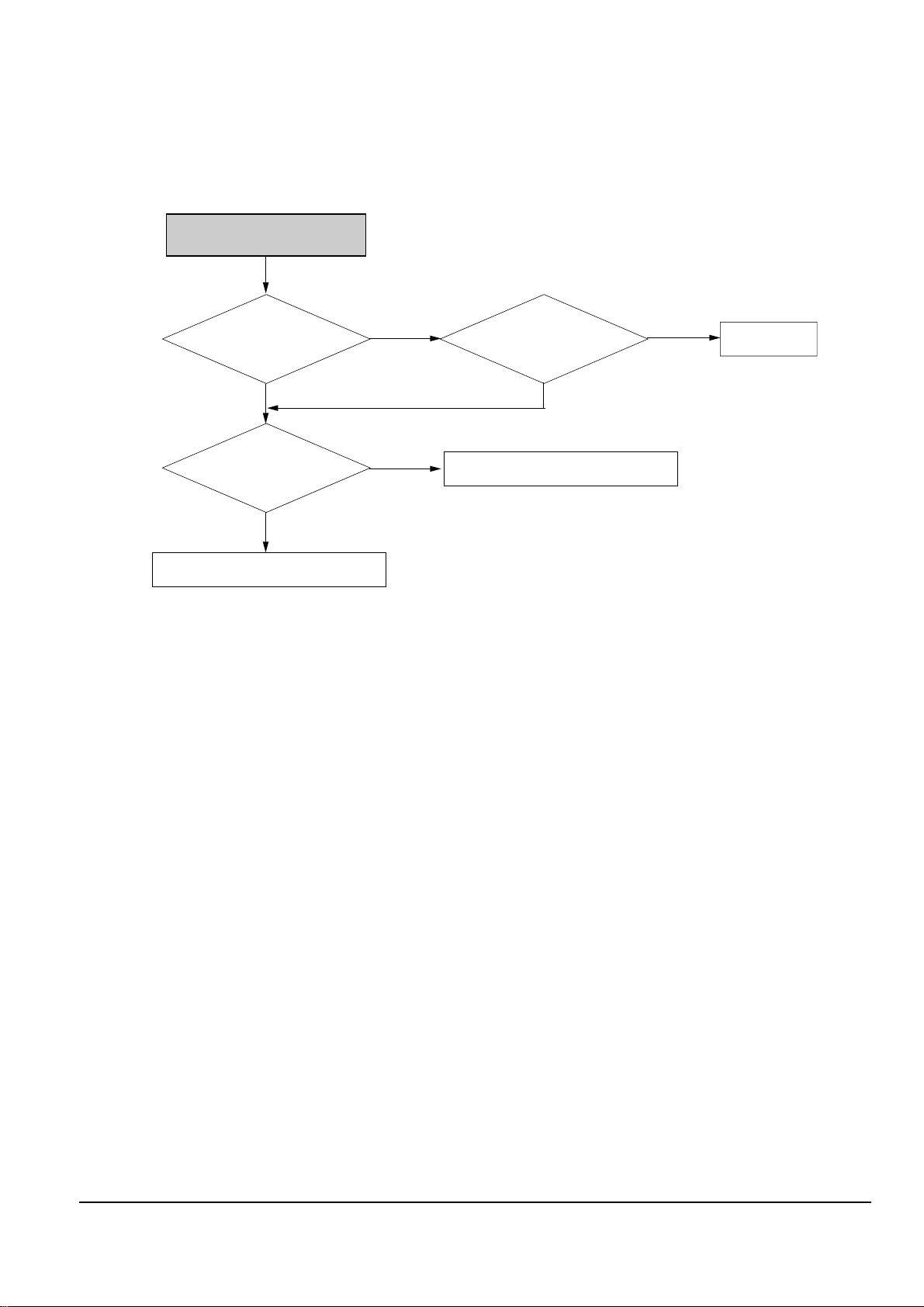
NO POWER (LED OFF)
Power switch and
power plug pin is
connected?
SMPS OK?
J301 (2, 5, 6, 7, 8, 9)
Check U901, U902
Connect switch and power Plug pin.
Yes
Yes
No
No
Check SMPS.
Front PCB ass'y is OK?
Yes
No
Check Front PCB ass'y.
U4(12, 13) signal?
: 27MHz CLK
No
Check X1.
Yes
R10 signal?
: 27MHz CLK
No
Check R10.
Yes
108MHz CLK is occurred
at R78, R79
Check U1
Yes
Yes
U4(8) signal?
: 27MHz CLK
No
Check U4.
Yes
No
Check U808.
Samsung Electronics 4-1
4. Troubleshooting

Troubleshooting
4-2 Samsung Electronics
NO LOCKING
U305 (5) is High?
(5 Volts)
U305 (3) DC Voltage is
H : 17~19V , L : 12.5~14V?
Check U1.
Check LNB Power On/Off at Menu.
Yes
Yes
No
No
Check CHIC1, SMPS(11, 12).
U902 Input
voltage L809 : 5V,
U901 Input vloltage
BD804 : 3.3V
Yes
No
Check U301, U304.
U901 Data, Control
appear at R930 ~ R940
No
Check U901.
Yes

Troubleshooting
Samsung Electronics 4-3
NO SPDIF OUTPUT
L602 is 5V?
Check L602, SMPS.
Yes
No
Check U1.
No
Data waveform
occur at U603(20)
U603(5, 6, 7, 8)
Data, CLK?
Yes
No
Check U603.
Yes
Check J600.
Troubleshooting
4-4 Samsung Electronics
NO VIDEO (TV SCART)
No
U800(4) Video signal ?
L804 Video signal ?
Yes
Yes
No
No
Check U1.
U800(44) Signal ?
Check R817.
Check U800.
Yes

Troubleshooting
Samsung Electronics 4-5
NO VIDEO (VCR SCART)
No
U800(4) Video signal ?
L804 Video signal ?
Yes
Yes
No
No
Check U1.
U800(44) Signal ?
Check R824.
Check U800.
Yes
 Loading...