

Samsung DSR-1-1P User Manual

Digital
Videocassette
Recor der
3-858-431-13(1)
Operating Instructions
Before operating the unit, please read this manual
thoroughly and retain it for future reference.
DSR-1/1P
1996 by Sony Corporation
1
Owner’s Record
The model and serial numbers are located on the upper side.
Record these numbers in the spaces provided below. Refer
to them whenever you call upon your Sony dealer regarding
this product.
ADVARSEL!
Lithiumbatteri - Eksplosionsfare ved fejlagtig håndtering.
Udskiftning må kun ske med batteri af samme fabrikat og
type.
Levér det brugte batteri tilbage til laverandøren.
Model No. Serial No.
WARNING
To prevent fire or shock hazard, do not
expose the unit to rain or moisture.
This symbol is intended to alert the user to the
presence of uninsulated “dangerous voltage”
within the product’s enclosure that may be of
sufficient magnitude to constitute a risk of electric
shock to persons.
This symbol is intended to alert the user to the
presence of important operating and
maintenance (servicing) instructions in the
literature accompanying the appliance.
LITHIUM BATTERY
Replace the battery with a Sony CR2032 lithium battery.
Use of another battery may present a risk of fire or
explosion.
ADVARSEL
Lithiumbatteri - Eksplosjonsfare.
Ved utskifting benyttes kun batteri som anbefalt av
apparatfabrikanten.
Brukt batteri returneres apparatleverandøren.
VARNING
Explosionsfara vid felaktigt batteribyte.
Använd samma batterityp eller en likvärdig typ som
rekommenderas av apparattillverkaren.
Kassera använt batteri enligt gällande föreskrifter.
VAROITUS
Paristo voi räjähtää jos se on virheellisesti asennettu.
Vaihda paristo ainoastaan laitevalmistajan suosittelemaan
tyyppiin.
Hävitä käytetty paristo valmistajan ohjeiden mukaisesti.
For customers in the USA
This equipment has been tested and found to comply with
the limits for a Class A digital device, pursuant to Part 15 of
the FCC Rules. These limits are designed to provide
reasonable protection against harmful interference when the
equipment is operated in a commercial environment. This
equipment generates, uses, and can radiate radio frequency
energy and, if not installed and used in accordance with the
instruction manual, may cause harmful interference to radio
communications. Operation of this equipment in a residential
area is likely to cause harmful interference in which case the
user will be required to correct the interference at his own
expense.
You are cautioned that any changes or modifications not
expressly approved in this manual could void your authority
to operate this equipment.
The shielded interface cable recommended in this manual
must be used with this equipment in order to comply with the
limits for a digital device pursuant to Subpart B of Part 15 of
FCC Rules.
WARNING
Battery may explode if mistreated.
Do not recharge, disassemble or dispose of in fire.
Note
Keep the lithium battery out of the reach of children.
Should the battery be swallowed, consult a doctor
immediately.
Caution
Television programs, films, video tapes and other
materials may be copyrighted. Unauthorized
recording of such material may be contrary to the
provisions of the copyright laws.

Table of Contents
Chapter 1
Overview
Chapter 2
Fitting and
Connecting
Related Equipment
Features .............................................................................7
Location and Function of Parts .....................................10
Power Supply .................................................................... 10
Display Section ................................................................. 11
Input/Output Connectors ................................................... 14
Recording/Playback Section ............................................. 16
Time Code Section ............................................................ 18
Inserting and Replacing the Lithium Battery ...............21
Example System Configuration .....................................23
Mounting on Video Camera ............................................24
Fitting the Shoulder Strap ................................................. 27
Connecting Audio System .............................................29
Using a Wireless Microphone System............................... 29
Using an External Audio System ...................................... 30
Power Supply...................................................................31
Chapter 3
Shooting
Using the BP-L40/L60A Battery Pack.............................. 31
Using an AC Power Source ............................................... 34
Cassettes for the DSR-1/1P............................................35
Shooting...........................................................................38
Back Space Editing.........................................................43
Starting Back Space Editing at Any Tape Position ........... 44
Playback — Checking Recorded Contents...................47
Checking the Recorded Contents Immediately After
Shooting — Recording Review.................................... 47
Viewing Monochrome Playback in the Viewfinder........... 47
Viewing Color Playback.................................................... 48
Table of Contents 3

Table of Contents
Chapter 4
Time V alues
—For Index of Recording
Points
Chapter 5
ClipLink Shooting
—Recording Information for
Editing
Switching Time Value Indications ..................................49
Resetting the Counter ........................................................ 49
Displaying the Date/Time ................................................. 49
Setting the User Bit Value...............................................50
Setting the Time Code Value ..........................................51
Making the Time Code Continuous
at Back Space Editing .................................................. 52
Setting the Time Code to the Real Time Clock
and Calendar................................................................. 52
Synchronization With External Time Code Signals
—Gen-Lock ......................................................................53
Connection for Gen-Lock.................................................. 53
Locking the Internal Time Code Generator
to the Reference Time Code......................................... 54
Recording Using ClipLink Function .............................55
Setting Editing Points While Shooting (When Using the
DXC-D30/D30P/D35/D35P) ....................................... 57
Resuming Recording in ClipLink Mode ........................58
Chapter 6
Menu
—For Settings
Contents of the VTR Menu..............................................61
VTR Menu Operation.......................................................62
Basic Operation ................................................................. 62
Setting the Real Time Clock and Calendar
—Menu 101 ................................................................. 63
Checking the Total Operating (Power-On) Hours
—Menu 201 ................................................................. 63
Selecting Frame Mode (DF/NDF) for Time Code
—Menu 204 (for DSR-1 Only) .................................... 63
Selecting Battery Capacity Indication —Menu 206 ......... 64
Setting Standby-On Period —Menu 207 .......................... 64
Using Auto-Check Function —Menu 210 ........................ 65
Selecting ClipLink Function —Menu 211 ........................ 67
Selecting Audio Recording Mode —Menu 212................ 67
4 Table of Contents

Chapter 6
Menu (continued)
—For Settings
Chapter 7
Maintenance
Appendix
Selecting Audio Reference Level —Menu 213................. 68
Settting Fade-In/Fade-Out for the Audio Recording
Start and Stop Points —Menu 214............................... 68
Using Setup Add (for DSR-1 Only) —Menu 220............. 69
Using Setup Remove1 (for DSR-1Only) —Menu 22 ....... 69
Cleaning the Video Heads ..............................................71
Warning System ..............................................................72
Condensation ..................................................................... 73
Troubleshooting ..............................................................74
Notes on Use ...................................................................77
Specifications..................................................................78
Glossary...........................................................................80
Index.................................................................................81
Table of Contents 5


Features
Chapter 1 Overview
The DSR-1/1P is a dockable VCR that uses the
DVCAM™ digital recording format.
The DSR-1/1P can be combined with a DXC-D30/
D30P/D35/D35P digital video camera or a DXC-637/
537A/327B series analog video camera. When docked
with the DXC-D30/D30P/D35/D35P, the DSR-1/1P
functions as a DVCAM digital camcorder.
New Functions as HighPerformance Digital Recording
VCR
The DSR-1/1P uses the DVCAM recording format.
The internal signal processing is digitalized to provide
more stable output signals and higher reliability.
Compatible with consumer DV
A DV cassette recorded on a DV-format VCR can be
played back on the DSR-1/1P. (Cassettes recorded in
LP mode cannot be played back.)
Creation of clips
Using the ClipLink function, the camera operator can
create clips to be used during editing.
The images captured at the Mark IN points are
recorded in a compressed format onto the tape as
“Index Pictures”. In addition, editing point-related data
(scene number, time code for Mark IN/OUT points,
etc.) is recorded in the cassette memory.
ClipLink mode
To use the ClipLink function, select the menu setting
to set the DSR-1/1P into ClipLink mode. There is also
a ClipLink continue function that enables clips to be
continued even after a break in recording.
PCM digital audio
Recording/playback can be set to audio lock mode.
Selectable between two-channel recording (with a
sampling frequency of 48 kHz) mode or four-channel
recording (with a sampling frequency of 32 kHz) mode
(channels 1 and 2 only).
Chapter 1 Overview
DVCAM cassettes
The DSR-1/1P can use both standard-size and minisize DVCAM cassettes. According to cassette size, the
DSR-1/1P automatically correct reel position.
The maximum recording/playback times are 184
minutes for standard size cassettes and 40 minutes for
mini cassettes.
DVCAM cassettes include a cassette memory.
Information about the editing points (ClipLink™ log
data) that is specified while shooting is recorded into
this cassette memory.
ClipLink™ function
The ClipLink function links all stages from shooting to
editing. Once editing points have been set with this
function during shooting, they can be used to boost the
efficiency of editing work.
Equipped with audio output connectors
During recording or playback, audio output can be
monitored via a built-in speaker, a connected earphone
or via (two-channel) audio output connectors.
Color playback
Connect an external video monitor for color playback
(playback adaptor not required). The DSR-1/1P is
equipped with two video monitor connectors: one for
composite video output and the other for S-video
output.
Chapter 1 Overview 7

Features
New Functions as DVCAM Digital
Camcorder
The following unique functions are available when you
Chapter 1 Overview
dock the DSR-1/1P with a DXC-D30/D30P/D35/D35P
digital video camera.
Freeze mix function
This function superimposes a freeze-frame from the
previous recorded scene to facilitate setting up the
same framework for a new scene.
Recording of camera setup data
SetupLog™ function
Settings at shooting are recorded onto the tape in real
time. This recorded data can then be used to reproduce
the same shooting conditions in subsequent shots. It
also makes it easier to identify the causes of problems
in previous shots.
Audio level adjustable from camera
You can use a knob on the camera’s front panel to
adjust the channel 1 audio recording level.
Standard Functions as a
Dockable VCR
The DSR-1/1P is equipped with all of the standard
functions of conventional dockable VCRs.
Back space editing
Press the VTR button on the camera or lens to link
recordings with ±0-frame accuracy. The recording
review function or edit search function can be used to
ensure continuous recording with the same accuracy
even after changing the tape position via playback/fast
forward/rewind or after removing the cassette.
SetupNavi™ function
The setup conditions selected using the camera setup
menu are recorded onto the tape along with setup file
settings. Using this function, the same settings can be
reproduced for each recording and the same setup can
be shared among several camcorders.
Edit search function
You can operate the search playback function in
forward or reverse (two search speeds are available)
right from the camera, without having to use the tape
transport buttons. This makes it easier to find a
recording start point when you restart shooting at any
point on the tape.
Time code display on viewfinder screen
during playback
The playback time code data can be superimposed on
the viewfinder screen.
Playback functions
Monochrome playback of recordings can be seen
through the camera’s viewfinder.
The recording review function automatically rewinds
and plays back the last few seconds of the recording.
Use this function to easily and quickly check
recordings.
Built-in time code generator/reader
The internal time code generator can record the time
code data that is required for high-precision editing.
Audio recording functions
In addition to using the camera’s built-in microphone,
sound can be recorded via a wireless microphone
system or an external audio system.
8 Chapter 1 Overview

Several power supply options
The DSR-1/1P can use the BP-L40/L60A Battery Pack
(for about 75/150 minutes of continuous operation
with the DXC-D30/D30P/D35/D35P).
•With an optional DC-L1 Battery Adaptor, the DSR-1/
1P can use the NP-1B Battery Pack (for about 60
minutes of continuous operation with the DXC-D30/
D30P/D35/D35P).
•With an optional DC-L90 Battery Adaptor, the DSR1/1P can use the BP-90A Lithium Battery Pack (for
about 130 minutes of continuous operation with the
DXC-D30/D30P/D35/D35P).
•With an optional AC-550/550CE/DN1/DN2A AC
Adaptor, the DSR-1/1P can operate on AC power.
Design for Easy Working
Equipped with both digital and analog
camera connectors
Chapter 1 Overview
The DSR-1/1P has both PRO 76-pin connector (for
digital camera connection) and the PRO 50-pin
connector (for analog camera connection). Connectors
are easy to replace.
Light and compact
The DSR-1/1P is compact and lightweight enough to
be used in the field.
Chapter 1 Overview 9
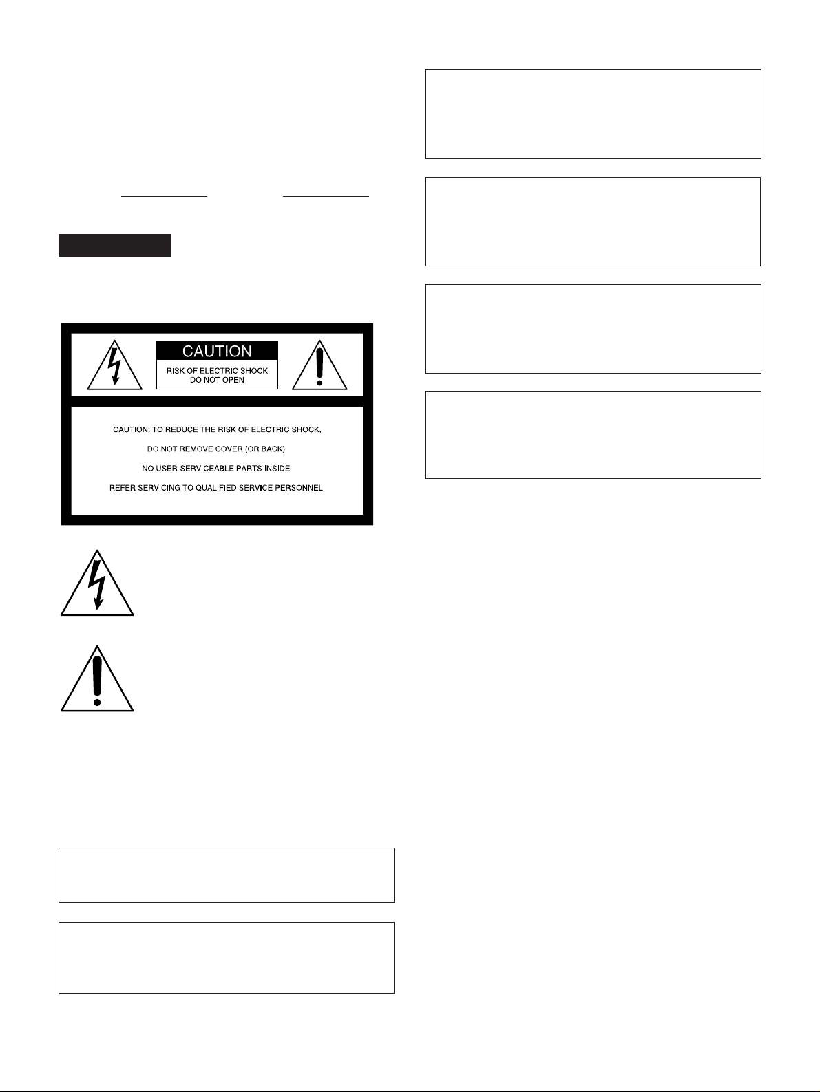
Location and Function of Parts
Power Supply
Chapter 1 Overview
1 Battery attachment interface
2 DC OUT connector
3 DC IN connector
4 POWER switch
Bottom view
1 Battery attachment interface
Attach a battery pack or an AC-DN1/DN2A AC
Adaptor.
For information about fitting a battery pack or an AC
adaptor, see “Power supply” (page 31).
2 DC OUT (DC power output) connector (4-pin,
female)
This connector supplies power for a WRR-855A/860A
UHF Portable Tuner.
5 BREAKER button
3 DC IN (DC power input) connector (XLR 4-pin,
male)
To use the DSR-1/1P with an AC power supply
connect an optional AC-550/550CE/CMA-8A/CMA8ACE AC Adaptor.
4 POWER switch
Turn the power supply on and off.
5 BREAKER (breaker reset) button
If an excessive current flows in the internal circuits,
the internal circuit breaker shuts off the power supply.
Push this button after eliminating the cause of the
excessive current.
10 Chapter 1 Overview
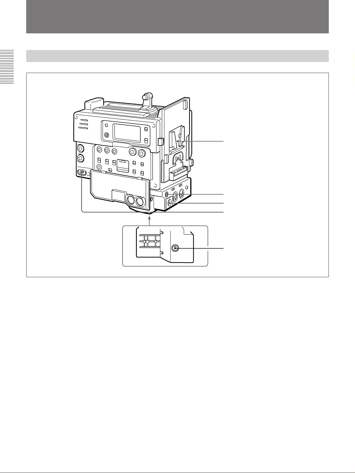
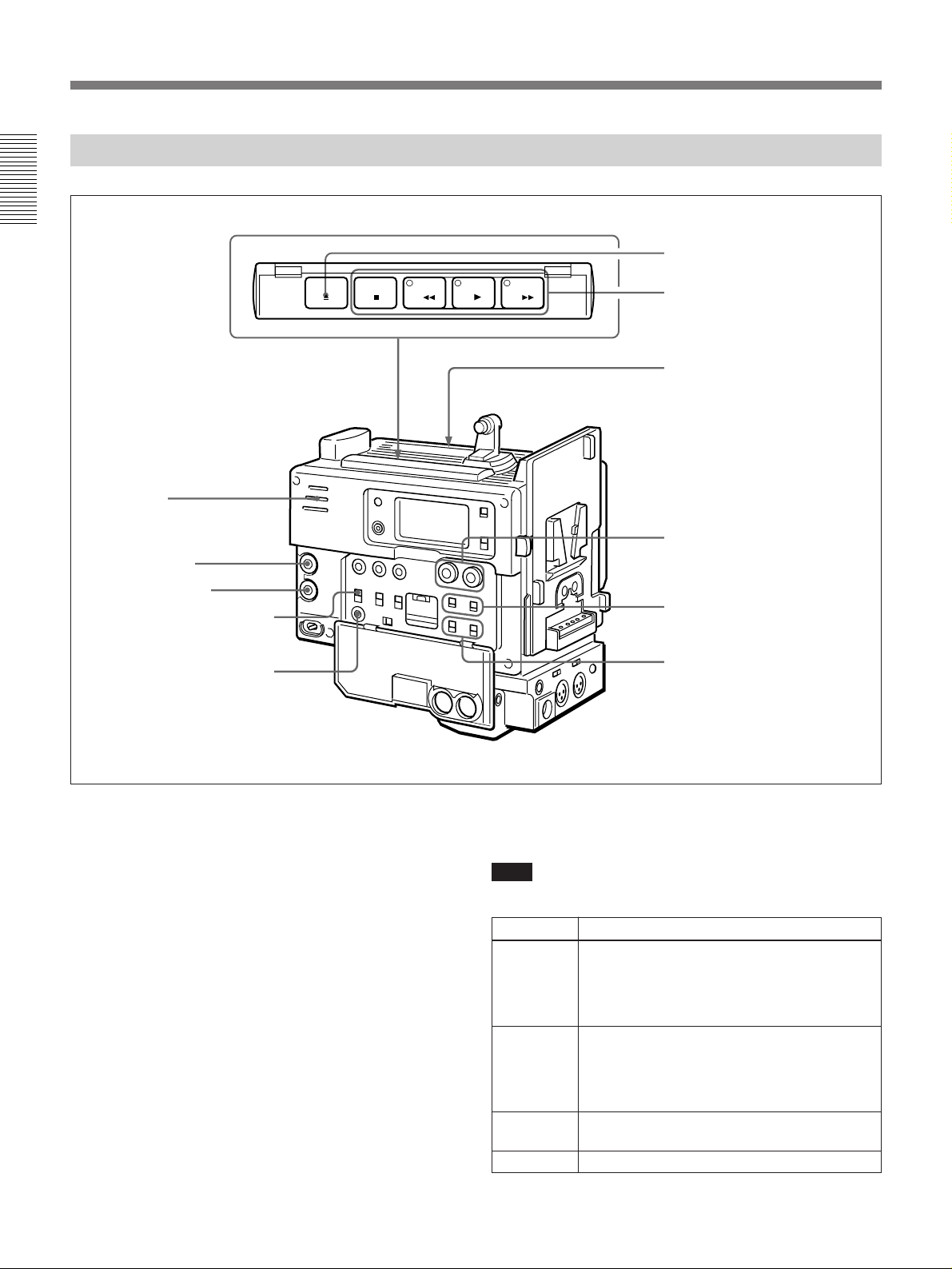
Display Section
1 Display window
Chapter 1 Overview
2 WARNING indicator
3 MENU button
1 Display window
The display window shows the following items. Use
the LIGHT switch 4 to light up the display window.
a Playback indication
b DATE indication
c Non drop-frame indication (DSR-1 only)
d External synchronization lock indication
4 LIGHT switch
5 BACK TALLY switch
6 TALLY indicator
s Time value indication
r Clip remaining indication
q Tape remaining indication
p Battery capacity indication
o Service indication
e Hold indication
PB DATE NDF EXT-LK HOLD
H MIN SEC FRM
CONT
DVCAM
IP
Li
CLIP
CL
TAPE
BATT
EF
DIAG
RF SERVO HUMID SLACK
n Warning indications
f Audio level indicators
dB
OVER OVER
0
-12
-20
-30
-40
∞
-
F
8
32k
1
2
F
8
48k
m Audio mode
indications
g ClipLink log data indication
h ClipLink continue indication
CONT
IP
CL
i IP indication
DVCAM
Li
j Lithium backup
battery warning
k DVCAM indication
l Cassette memory indication
Chapter 1 Overview 11

Location and Function of Parts
Indications in the display window
Indication Description
a Playback indication Appears during playback, fast forward or rewind with the time data display
b DATE indication Appears when the date or time is displayed in the time value indication s area.
Chapter 1 Overview
d External synchronization lock indication
e Hold indication Appears when the internal time code generator is stopped.
f Audio level indicators These show the audio recording or playback levels of channel 1 and channel 2.
g ClipLink log data indication Appears when using a cassette with cassette memory containing ClipLink log
h ClipLink continue indication Appears when back space editing using ClipLink function is possible.
i IP (index picture) indication Appears when the ClipLink function is set to on in the VTR menu and index
j Lithium backup battery warning Appears when the voltage of the internal lithium backup battery (CR2032) is low.
k DVCAM indication Disppears when the cassette being played back is not for DVCAM format.
l Cassette memory indication Appears when using a cassette with cassette memory.
m Audio mode indications
showing a time code or user bit value.
Appears when non drop-frame mode is selected.c Non drop-frame indication (DSR-1 only)
Appears when the internal time code generator is locked to an external signal
input to the TC IN connector.
data.
picture recording is allowed.
If this indication appears, replace the lithium backup battery immediately.
For further information about replacing lithium batteries, see “Inserting and Replacing
the Lithium Battery” (page 21).
These show audio recording/playback mode.
Fs32k: 4-channel mode (32 kHz sampling frequency)
Fs48k: 2-channel mode (48 kHz sampling frequency)
For further information about selecting audio recording mode, see “Selecting Audio
Recording Mode —212” (page 67).
n Warning indications
o Service indication Appears during maintenance on menu operations. It does not appear during
p Battery capacity indication
Include the following.
RF: Appears when the video heads are clogged, or when there is a fault in the
recording system.
SERVO: Appears when the servo lock is not functioning.
HUMID: Appears when there is condensation on the drum.
SLACK: Appears when there is a tape winding fault.
For measures against warning indications, see “Warning System” (page 72).
normal operation.
This indicates the battery capacity and voltage as shown below.
Change menu setting for the battery you are using.
For menu setting, see “Selecting Battery Capacity Indication —Menu 206” (page 64).
indication Battery voltage
BP-L40/L60A NP-1B/BP-90A
BATT E [pppppp] F 15.0 V or more 12.5 V or more
BATT E [ppppp ] F 14.0 to 15.0 V 12.0 to 12.5 V
BATT E [pppp ] F 13.0 to 14.0 V 11.75 to 12.0 V
BATT E [ppp ] F 12.0 to 13.0 V 11.5 to 11.75 V
BATT E [pp ] F 11.3 to 12.0 V 11.3 to 11.5 V
BATT E [p ] F (blinking)
BATT E [p ] F (blinking) 11.0 to 11.25 V 11.0 to 11.25 V
BATT E [ ] F (blinking) 11.0 V or less 11.0 V or less
a)
11.25 to 11.3 V 11.25 to 11.3 V
12 Chapter 1 Overview
a) Replace the battery pack when this indication appears.
(Continued)

Indications in the display window (continued)
Indication Description
q Tape remaining indication
During recording or pause mode, this indication shows the remaining tape time as
shown below. It is not displayed when no cassette is loaded.
Indication Tape time remaining
TAPE ppppppp 30 minutes or more
TAPE pppppp 25 to 30 minutes
TAPE ppppp 20 to 25 minutes
TAPE pppp 15 to 20 minutes
TAPE ppp 10 to 15 minutes
TAPE pp 5 to 10 minutes
TAPE p 2 to 5 minutes
TAPE p (blinking) 0 to 2 minutes
TAPE (blinking) End of tape
r Clip remaining indication
s Time value indication Depending on the DISPLAY switch setting, this shows a counter value, time code
This shows how many clip shots can still be recorded.
Indication Index picture Cue point
CLIP pppppp 51 pictures or more 101 points or more
CLIP ppppp 41 to 50 pictures 81 to 100 points
CLIP pppp 31 to 40 pictures 61 to 80 points
CLIP ppp 21 to 30 pictures 41 to 60 points
CLIP pp 11 to 20 pictures 21 to 40 points
CLIP p 1 to 10 pictures 1 to 20 points
CLIP p (blinking)
CLIP Cannot record
CLIP (blinking)
a) When back space editing using ClipLink function is possible (when CONT
appears)
value, or user bit value. Press the MENU button 3 to display the VTR menu.
a)
a)
1 to 3 pictures 1 to 6 points
Cannot record
Chapter 1 Overview
2 WARNING indicator
This lights or blinks when an abnormality occurs.
For details, see “Warning System” on page 72.
3 MENU button
Press this button to display the VTR menu in the
display window 1.
For details about the VTR menu, see Chapter 6 “Menu”.
4 LIGHT switch
This switches the display window 1 light on and off.
5 BACK TALLY switch
Set this switch to ON to activate the TALLY indicator
6 function.
6 TALLY (back tally) indicator (red)
This indicator lights during recording. It will not light
if the BACK TALLY switch 5 is set to OFF. This
indicator also blinks to indicate warnings in the same
manner as the REC/TALLY indicator in the
viewfinder of the camera.
For details, see “Warning System” on page 72.
Chapter 1 Overview 13
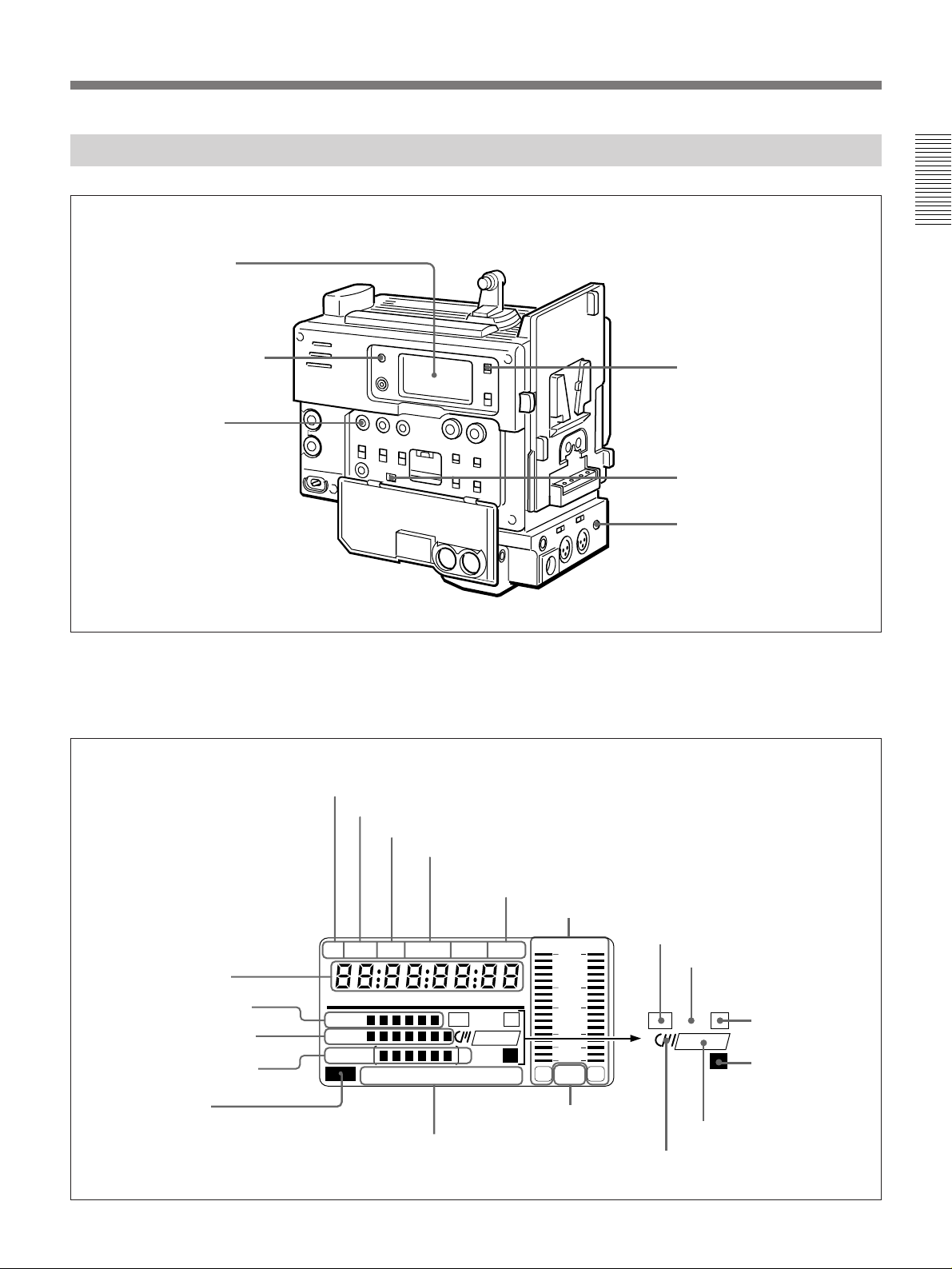
Location and Function of Parts
Input/Output Connectors
Chapter 1 Overview
1 TC OUT connector
2 TC IN connector
3 GEN LOCK IN connector
4 AUDIO OUT CH-1/CH-2 connectors
Shoulder strap fitting
5 Camera connector
Rear
DC OUT
12V
DC IN
LINE MIC
+48V ON
CH-1 AUDIO IN CH-2
1 TC OUT (time code output) connector (BNC)
This outputs time code signals from the built-in time
code generator. When a time code signal is input to the
TC IN connector 2, this output signal is synchronized
to it.
For details about time code, see “Setting Time Code Value”
on page 51.
6 S VIDEO OUT connector
7 VIDEO OUT connector
+48V ON
LINE MIC
TALLY
8 AUDIO IN CH-1/
CH-2 connectors and
input selection switches
9 EARPHONE connector
2 TC IN (time code input) connector (BNC)
Input an external signal for synchronizing the built-in
time code generator. Use an SMPTE (DSR-1) or EBU
(DSR-1P) time code signal.
Note
Use a jitterless LTC signal. Using an LTC signal
reproduced by other equipment may cause the DSR-1/
1P to malfunction.
14 Chapter 1 Overview

3 GEN LOCK IN (gen lock video input) connector
(BNC)
When synchronizing the camera to an external signal,
input a reference video signal (VBS or BS).
4 AUDIO OUT CH-1/CH-2 connectors (phono
jacks)
These output the sound being recorded or played back.
Connect to a stereo amplifier or video monitor’s audio
input connectors.
5 Camera connector (PRO 76-pin DIGITAL or
PRO 50-pin)
Connect to the camera’s VTR connector. Two types of
connectors are provided and can be replaced according
to the camera.
PRO 76-pin DIGITAL: For connecting to the DXC-
D30/D30P/D35/D35P digital video camera.
PRO 50-pin: For connecting to the DXC-327B/537A/
637A (or DXC-327BP/537AP/637AP) series
analog video camera.
For details on replacing camera connectors, see “Mounting
on Video Camera” (page 24).
8 AUDIO IN CH-1/CH-2 (audio input channel 1
and 2) connectors (XLR 3-pin, female) and input
selection switches
Connect a microphone or other external audio
equipment. Set the input selection switches as shown
below according to the microphone or equipment.
MIC +48V ON (right position): For connecting to a
48-V microphone
Note
If this position is selected for a microphone other
than 48-V microphone, the microphone may be
damaged.
MIC (center position): For connecting any
microphone other than 48-V microphone
LINE (left position): For connecting an external audio
signal source such as a stereo amplifier.
9 EARPHONE connector (mini-jack)
Connect an earphone or headphones. This outputs the
sound which was output to the speaker, but mutes the
speaker.
Chapter 1 Overview
6 S VIDEO OUT (S-video output) connector (DIN
4-pin)
This outputs the image being shot or played back as Svideo signals. Connect to the S-video input connector
on a VCR or video monitor.
Note
When the CA-514/514P Camera Adaptor is connected,
only playback audio is output from this connector.
7 VIDEO OUT (composite video output)
connector (BNC)
This outputs the image being shot or played back as
composite video signals. Connect to the video input
connector on a VCR or video monitor.
Notes
•The output signal from this connector may
discontinue when switching the operation between
recording and playback. Do not use as a reference
signal for external equipment.
•When the CA-514/514P Camera Adaptor is
connected, only playback audio is output from this
connector.
Chapter 1 Overview 15
Location and Function of Parts
Recording/Playback Section
Chapter 1 Overview
1 EJECT button
6 Speaker
7 ALARM knob
8 MONITOR knob
9 MONITOR SELECT switch
0 ClipLink CONTINUE button
EJECT
STOP
PLAYREW
F FWD
2 Tape transport buttons and
indicators
Cassette holder
3 AUDIO LEVEL (CH-1/CH-2)
knobs
4 AUDIO SELECT (CH-1/CH-2)
switches
5 AUDIO IN (CH-1/CH-2)
switches
1 EJECT button 6
Press this button to open the cassette holder.
16 Chapter 1 Overview
2 Tape transport buttons and indicators
These buttons transport the tape as shown below.
Note
During recording, none of these buttons operates.
Button Operation
REW 0 Rewinds the tape. The indicator lights while
F FWD ) Fast forwards the tape. The indicator lights
PLAY ” Plays back the recorded video. The indicator
STOP p
the tape is being rewound.
Press while the tape is being rewound or
during playback to view reverse search
playback.
while the tape is being fast forwarded.
Press while the tape is being fast forwarded
or during playback to view forward search
playback.
lights during playback.
Stops the tape.

3 AUDIO LEVEL (CH-1/CH-2) (audio recording
level adjustment for channels 1 and 2) knobs
When the AUDIO SELECT (CH-1/CH-2) switches 4
are set to MANUAL, these knobs adjust the audio
levels being recorded on channels 1 and 2.
The audio levels are indicated in the display window. For
details, see “1 Display window” in “Display Section on
page 11.
4 AUDIO SELECT (CH-1/CH-2) (audio recording
level adjustment manual/auto selection for channels
1 and 2) switches
These select the audio recording level adjustment
method.
AUTO: Use the AGC (automatic gain control) circuit
to automatically adjust the audio level.
MANUAL: Enables users to manually adjust the
AUDIO LEVEL (CH-1/CH-2) knobs for each
channel. Select AUTO if excess input levels are
likely to occur.
5 AUDIO IN (CH-1/CH-2) (audio input selection
for channels 1 and 2) switches
These select the input signals to channels 1 and 2.
CAM: Signals from the microphone connected to the
camera’s MIC IN +48V connector or from the
camera’s built-in microphone.
REAR: Signals from a microphone or external
equipment connected to the AUDIO IN (CH-1/CH-
2) connectors.
7 ALARM (alarm tone volume adjustment) knob
This controls the volume of the warning tone that is
output via the speaker 6 or earphone. Turning this
knob to the minimum setting mutes the alarm tone.
Chapter 1 Overview
8 MONITOR (monitor volume adjustment) knob
This controls the volume of the sound other than the
warning tone that is output via the speaker 6 or
earphone. Turning this knob to the minimum setting
mutes the audio output.
9 MONITOR SELECT (audio monitor selection)
switch
This selects audio output via the speaker 6 or
earphone.
CH-1: Channel 1 audio
MIX: Mixed audio (channels 1 and 2)
CH-2: Channel 2 audio
0 ClipLink CONTINUE button
When restart ClipLink shooting, press this button to
add the new clip at the end of the recorded clips.
Note
If you restart recording without pressing this button,
the pre-recorded ClipLink log data and index pictures
are deleted.
For details, see Chapter 5 “ClipLink Shooting”.
6 Speaker
Outputs the recorded or playback audio. When a
warning indicator appears in the viewfinder or display
window, the speaker sounds a warning tone.
The speaker is muted (does not output a warning tone)
when an earphone is connected to the EARPHONE
connector.
For details on the warning tone, see “Warning System”
(page 72).
Chapter 1 Overview 17

Location and Function of Parts
Time Code Section
Chapter 1 Overview
WARNING
RESET
(MENU SET)
MENU ADVANCE SHIFT
MONITOR SELECT
CH-1
MIX
CH-2
ClipLink CONTINUE
PRESET
DATE/TIME
BACK TALLY
OFF
F-RUN
REGEN SET
R-RUN
ON
AUDIO LEVEL
AUTO
MANUAL
AUDIO SELECT
CH-1 CH-2
AUDIO IN
CAM
REAR
1 RESET/(MENU SET) (counter reset/VTR menu
set) button
Resets the time value shown in the display window.
This button operates differently depending on settings
of the DISPLAY switch 2 and the TC mode switch 2
5.
LIGHT
ON
OFF
1 RESET/(MENU SET) button
DISPLAY
COUNTER
U-BIT
TC
2 DISPLAY switch
3 ADVANCE button
4 SHIFT button
5 TC mode switch 2
6 TC mode switch 1
Switch setting RESET button operation
DISPLAY: COUNTER Resets counter value to
0:00:00.
DISPLAY: TC
TC mode switch 1: PRESET
Resets time code to
00:00:00:00.
TC mode switch 2: SET
DISPLAY: U-BIT
TC mode switch 1: PRESET
Resets user bit
00.
TC mode switch 2: SET
a) Bits of time code recorded on tape, in which users can
record necessary information.
a)
to 00 00 00
18 Chapter 1 Overview

Also, this button is used to change menu settings.
For details on the VTR menu, see Chapter 6 “Menu”.
2 DISPLAY switch
Switches time value indication shown in the display
window.
COUNTER: Shows the tape transport time in
HH:MM:SS (hours, minutes, and seconds).
TC: Shows the time code value.
U-BIT: Shows the user bit data in the time code.
5 TC (time code) mode switch 2
Sets the mode for advancing time code values when
the TC mode switch 1 6 has been set to PRESET.
F-RUN: The time code advances continuously
whether or not the DSR-1/1P is recording. Use this
setting to align the time code value with real time.
SET: Use this setting to set the time code or user bit
value.
R-RUN: The time code value advances only during
recording. Use this setting to have consecutive time
code values for consecutive recordings on the tape.
Chapter 1 Overview
For information about the display window, see “1 Display
window” in “Display Section” on page 11.
3 ADVANCE button
When setting time code and user bit values, or at menu
setting, press this button to increment the digit that has
been selected with the SHIFT button 4. In other case,
keep pressing this button to show the clip remaining
indication instead of time value. (Example:
D45
)
For time code and user bit settings, see pages 50 and 51.
On how to use the ADVANCE button for menu settings, see
Chapter 6 “Menu”.
CLIP
4 SHIFT button
When setting time code and user bit values, or at menu
setting, keep pressing this button to select a digit. The
selected digit will start blinking.
In other case, keep pressing this button to show the
date (when the DISPLAY switch 2 is set to U-BIT)
and time (when the DISPLAY switch 2 is set to TC)
instead of time value.
For time code and user bit settings, see pages 50 and 51.
On how to use the ADVANCE button for menu settings, see
Chapter 6 “Menu”.
Note for the DSR-1
There are two time code frame modes: drop-frame
(DF) mode and non drop-frame (NDF) mode. This
product is shipped with drop-frame mode selected.
For details on switching between drop-frame mode and non
drop-frame mode, see “Selecting Drop-frame (DF)/Nondrop frame (NDF) mode (for DSR-1) —Menu 204” on page
63.
For details on drop-frame mode and non drop-frame mode,
see “Drop-frame mode (for DSR-1 Only)” on page 52.
6 TC (time code) mode switch 1
Selects between resetting the time code value or
continuing from the time code value at the end of the
previous recording.
PRESET: This starts recording time code values on
the tape from the currently set value.
REGEN: This reads the tape’s current time code value
and sets the time code to record starting from that
value. This ensures that the tape’s time code will be
continuous, even if there is a break in recording.
The time code value is advanced in R-RUN mode
regardless of the setting on TC mode switch 2 5.
DATE/TIME: This synchronizes the time code to the
real time clock set in the VTR menu (see page 63).
In this case the time code of the DSR-1 is recorded
in DF (drop-frame mode).
Note
If the ClipLink function is set to on (meaning ClipLink
shooting is allowed) in menu 211 and
CONT is
displayed in the display window, regardless of the
setting of this switch, the time code generator
automatically enters the REGEN mode at recording.
(The ClipLink function is factory-set to on.)
When you will not perform ClipLink shooting, set the
ClipLink function to oFF (see page 67).
Chapter 1 Overview 19


Inserting and Replacing the Lithium Battery
The DSR-1/1P uses a lithium battery to retain stored data. When using the
DSR-1/1P for the first time, be sure to insert the supplied lithium
battery (CR2032). The DSR-1/1P will not operate correctly without this
lithium battery.
Lifetime of the lithium battery
When the lithium battery’s voltage falls, the lithium backup battery
warning
the lithium battery (CR2032) within three or four days.
The lithium battery has an average service life of about two years, however
operation in ClipLink mode will shorten the lifetime until about one year.
Inserting or replacing the lithium battery
Notes
•Carefully read the instructions for inserting and replacing the lithium
battery. Lithium batteries may explode if misused.
•Use only CR2032 Lithium Batteries. Other types of lithium batteries may
come loose when the camcorder is moved. If you have difficulty finding
CR2032 Lithium Batteries, contact your Sony dealer.
appears in the display window. If this warning appears, replace
Li
Chapter 2 Fitting and Connecting Related Equipment
Chapter 2 Fitting and Connecting Related Equipment
1 Turn the POWER switch on.
2 Press down the catch at the top
of the battery cover and open
the cover.
3 Take out the lithium battery.
1 POWER switch
Catch
2 Press and pull forward.
LI
LITHIUM BATT
Press down and pull out toward you.
Battery cover
(Continued)
Chapter 2 Fitting and Connecting Related Equipment 21

Inserting and Replacing the Lithium Battery
4 Reverse step 3 to insert a
replacement lithium battery.
Make sure that the + symbol
on the battery is facing you.
5 Close the battery cover.
Chapter 2 Fitting and Connecting Related Equipment
22 Chapter 2 Fitting and Connecting Related Equipment
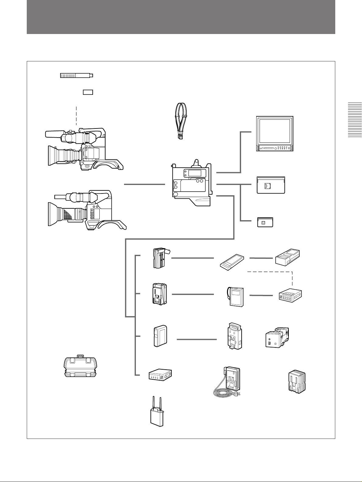
Example System Configuration
This product can be used with the equipment shown below.
ECM-672 Electret Condenser Microphone
CAC-12 Microphone Holder
DXC-D30/D30P/D35/D35P
Color Video Camera
DXC-637/537/537A/327A/327B
(or DXC-637P/537P/537AP/327AP/
327BP) series Color Video Camera
Shoulder strap (supplied)
DSR-1/1P (this product)
DC-L1 Battery
Adaptor
DC-L90
Battery Adaptor
NP-1B Battery
Pack
BP-90A Battery
Pack
Chapter 2 Fitting and Connecting Related Equipment
Color TV or color video monitor
DVCAM standard-size cassette
tape
DVCAM mini-size cassette tape
BC-1WD/
1WDCE
Battery
Charger
BC-410/410CE
Battery Charger
LC-421 Carrying Case
BP-L40/60A
Battery Pack
CMA-8A/8ACE
AC-550/550CE AC Adaptor
WRR-855A
UHF Synthesized
Tuner
(with BTA-801)
BC-L50 Battery
Charger
AC-DN1 AC
Adaptor
Chapter 2 Fitting and Connecting Related Equipment 23
BC-L100/L100CE
Battery Charger
AC-DN2A AC
Adaptor

Mounting on Video Camera
Chapter 2 Fitting and Connecting Related Equipment
Using the DXC-D30/D30P/D35/D35P
1 Loosen the two screws (M3)
and remove the cover from the
PRO 50-pin connector.
The DSR-1/1P is dockable with the DXC-D30/D30P/D35/D35P digital
video camera or with a DXC-637/537/537A/327A/327B series analog
video camera.
Switch the camera connectors according to the camera to be used.
Using a DXC-D30/D30P/D35/D35P: Use the PRO 76-pin DIGITAL
connector.
Using a DXC-637 series camera: Use the PRO 50-pin connector.
Note
Turn the POWER switch off before mounting the DSR-1/1P on the video
camera.
Replace the PRO 50-pin connector with the PRO 76-pin DIGITAL
connector.
2 Press the right side of the PRO
50-pin connector until the PRO
76-pin DIGITAL connector
appears.
The both connectors swing to
switch the positions by
pressing either of them.
PRO 50-pin connector
Cover
PRO 50-pin connector PRO 76-pin DIGITAL connector
24 Chapter 2 Fitting and Connecting Related Equipment
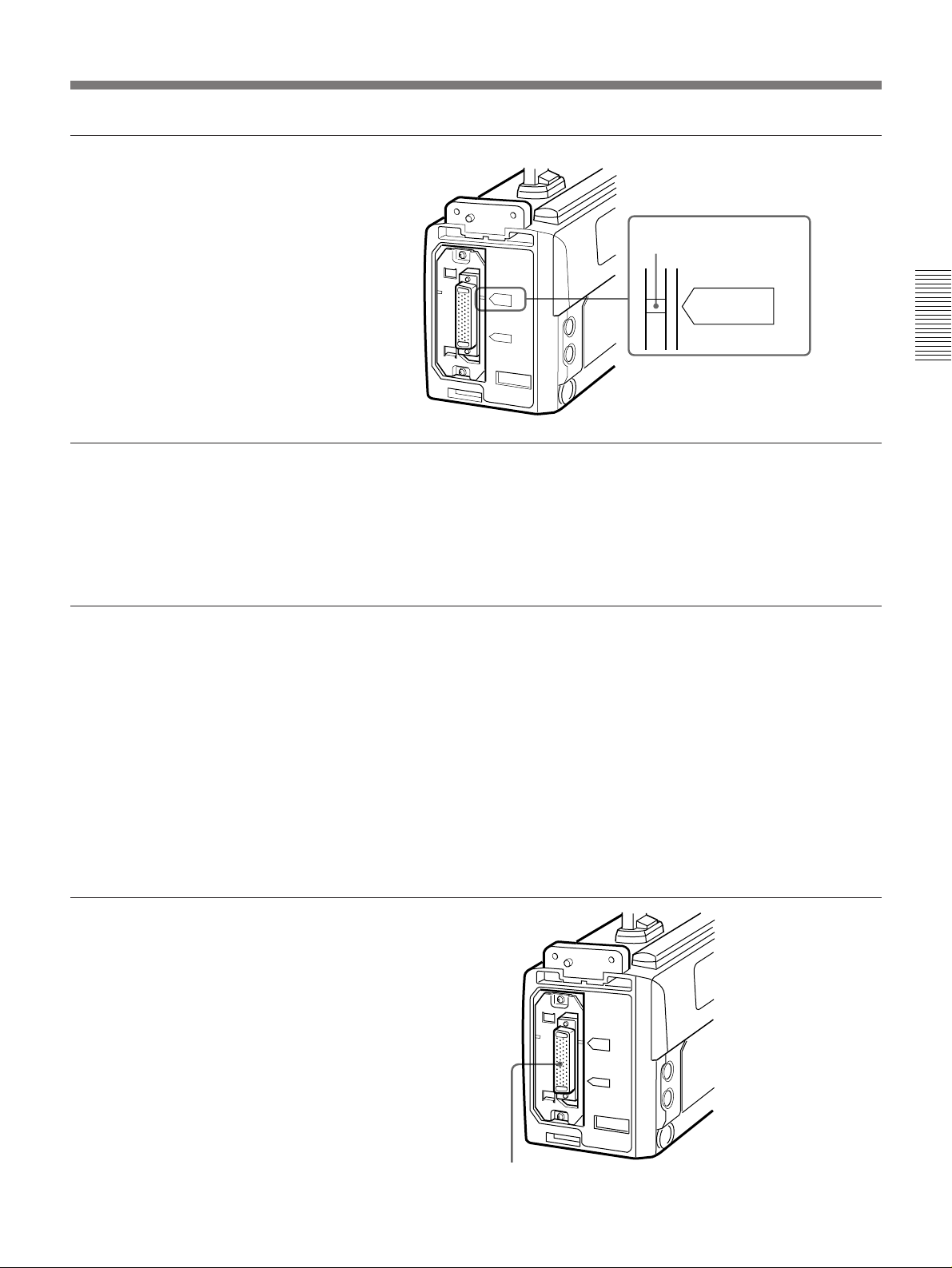
3 Attach the cover upside down.
Make sure that the match mark
lines up with the PRO76P
DIGITAL indication.
Using the DXC-637/537/537A/327A/327B series camera
Replace the PRO 76-pin DIGITAL connector with the PRO 50-pin
connector. Press the left side of the PRO 76-pin DIGITAL connector until
the PRO 50-pin connector appears. Make sure that the match mark lines up
with the PRO50P indication.
Mounting on the camera
Match mark
PRO76P
DIGITAL
Chapter 2 Fitting and Connecting Related Equipment
1 If necessary, replace the PRO
50-pin connector with the PRO
76-pin DIGITAL connector.
For details, see “Using the DXCD30/D30P/D35/D35P” (on
previous page).
This section describes the procedure for mounting the DSR-1/1P on a
DXC-D30/D30P/D35/D35P. Use the same procedure for mounting on a
DXC-637 series camera. (Replace the PRO 76-pin DIGITAL connector
with the PRO 50-pin connector.)
When using the camcorder grip
When configuring a camcorder with the camera, a camcorder grip (not
supplied) can be attached instead of the camera grip.
For instructions on attaching the grip, see the operating instructions for the
camera.
PRO 76-pin DIGITAL connector
Chapter 2 Fitting and Connecting Related Equipment 25
(Continued)
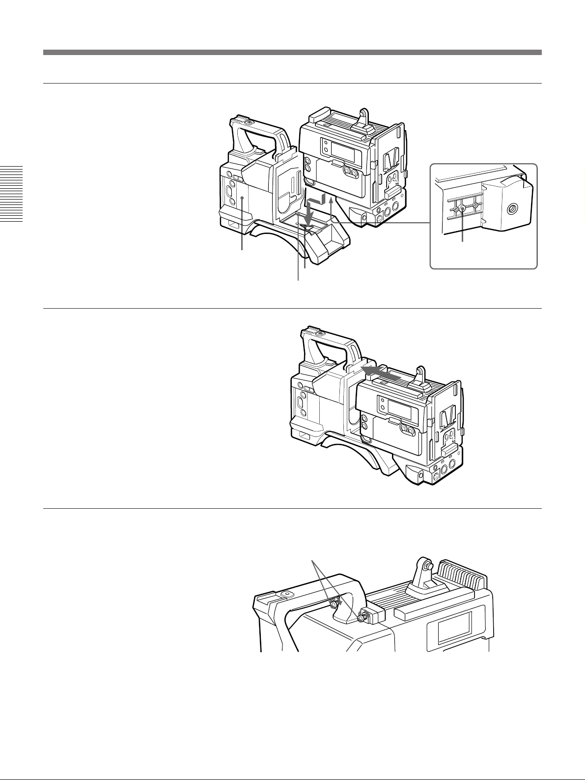
Mounting on Video Camera
2 Fit the projection on the
bottom of the DSR-1/1P into
the slot on the camera.
Chapter 2 Fitting and Connecting Related Equipment
3 Slide the DSR-1/1P along the
groove on the camera, and
press firmly until fixed.
4 Tighten the two screws (M4 ×
12) in the figure.
Camera
Projection
Slot
Groove
26 Chapter 2 Fitting and Connecting Related Equipment
M4 × 12 screws
 Loading...