


RHLL-HM2417AA
FORM NO. H11-524 REV. 8
Supersedes Form No. H11-524 Rev. 7
AIR HANDLERS
AIR HANDLERS
RHLL- High Efficiency
featuring Industry Standard
R-410A Refrigerant
RHSL- Standard Efficiency
featuring Industry Standard
R-410A Refrigerant
Features
■
RHLA/RHLL feature GE’s new X-13 (ECM) motor which
provides enhanced SEER performance with most Rheem
outdoor units.
■
1
1
/2 ton [5.3 kW] through 5 ton [17.6 kW] models are
between 42
1
/2 to 55
1
/2 inches [1080 to 1410 mm] tall and 22
inches [559 mm] deep.
■
Versatile 4-way convertible design for upflow, downflow,
horizontal left and horizontal right applications.
■
Factory-installed high efficiency indoor coil.
■
All models meet or exceed 330 to 400 CFM [156 to 189 L/s]
per ton at .3 inches [.7 kPa] of external static pressure.
■
Enhanced airflow up to .7" external static pressure.
■
Sturdy construction with 1.0 inch [.24 kPa] of reinforced foil
faced jacket insulation for excellent thermal and sound
insulation.
■
Field-installed auxiliary electric heater kits provide exact
heat for indoor comfort. Kits include circuit breakers which
meet UL and cUL requirements for service disconnect.
2 Rheem Heating, Cooling and Water Heating
Engineering Features
GENERAL TERMS OF LIMITED WARRANTY
Rheem will furnish a replacement for any part of this product
which fails in normal use and service within the applicable
periods stated, in accordance with the terms of the limited
warranty.
Conditional Parts (Registration Required) .........Ten (10) Years
For Complete Details of the Limited Warranty, Including
Applicable Terms and Conditions, See Your Local Installer or
Contact the Manufacturer for a Copy.
RHLL/RHSL- Series
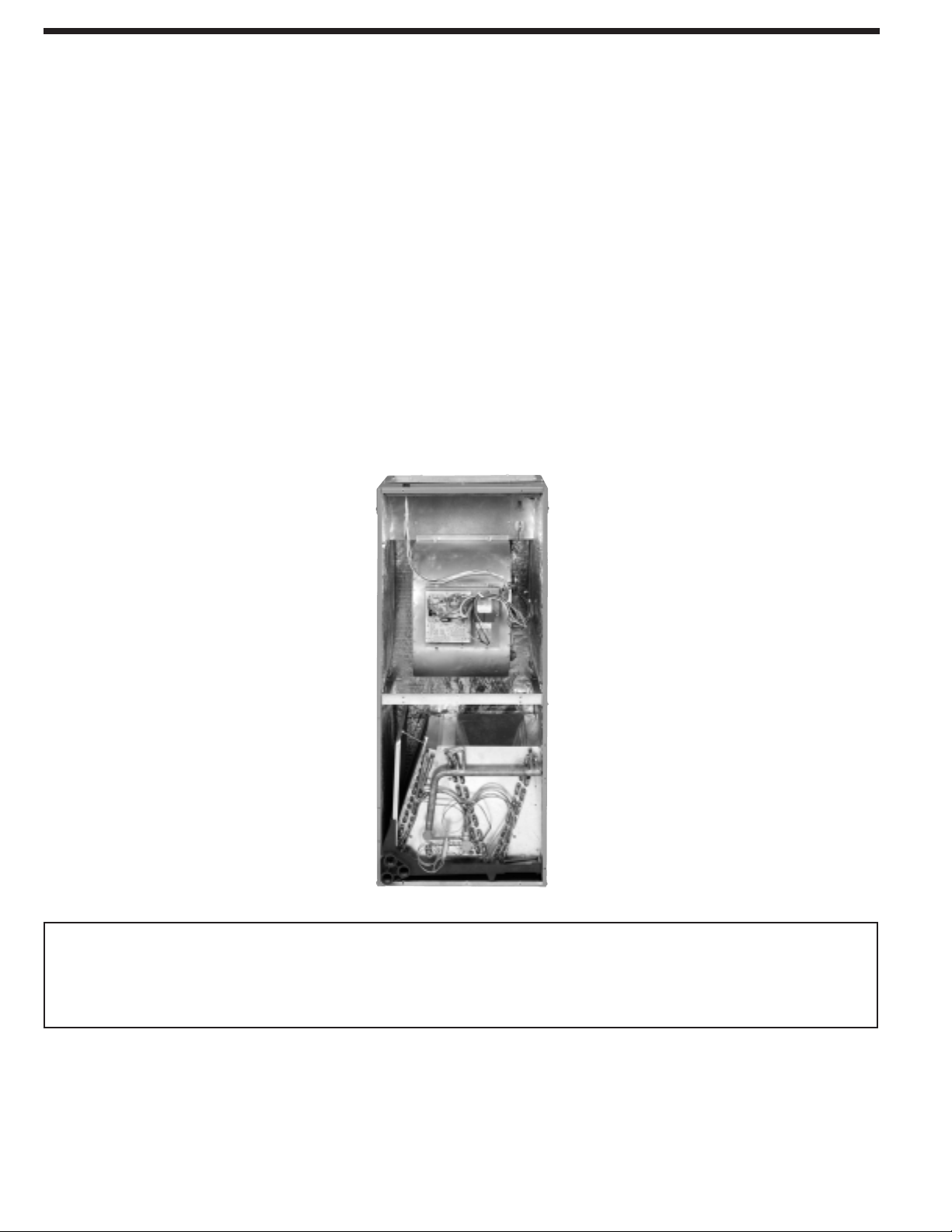
■
The most compact unit design available, all standard heat air
handler models only 42
1
/2 to 55
1
/2 inches [1079 to 1409 mm] high.
■
Attractive pre-painted cabinet exterior.
■
Rugged wall steel cabinet construction, designed for added
strength and versatility.
■
1.0" foil faced insulation mechanically retained in blower
compartment for excellent thermal and sound performance.
■
Four leg blower motor mount.
■
Blower housing with controls, motor and blower. Slide out
design for service and maintenance convenience.
■
Traditional open wire element design for heat applications.
■
Field convertible for vertical downflow, horizontal left hand or
right hand air supply.
■
3 combustible floor base accessories fit all model sizes when
required for downflow installations on combustible floors.
■
Indoor coil design provides low air side pressure drop, high
performance and extremely compact size.
[ ] Designates Metric Conversions
■
Expansion valve on indoor coil provides for operation with air
conditioning or heat pump using the same coil.
■
Coils are constructed of aluminum fins bonded to internally
grooved copper tubing.
■
Molded polymer corrosion resistant condensate drain pan is
provided on all indoor coils.
■
Supply duct flanges provided as standard on air handler cabinet.
■
Provisions for field electrical, connections available from either
side or top of the air handler cabinet.
■
Connection point for high voltage wiring is inside the air handler
cabinet. Low voltage connection is made on the outside of the
air handler cabinet.
■
Concentric knockouts are provided for power connection to
cabinet. Installer may pull desired hole size up to 2 inches
[51 mm] for 1
1
/2 inch [38 mm] conduit.
■
Front refrigerant and drain connections.
Rheem Heating, Cooling and Water Heating 3
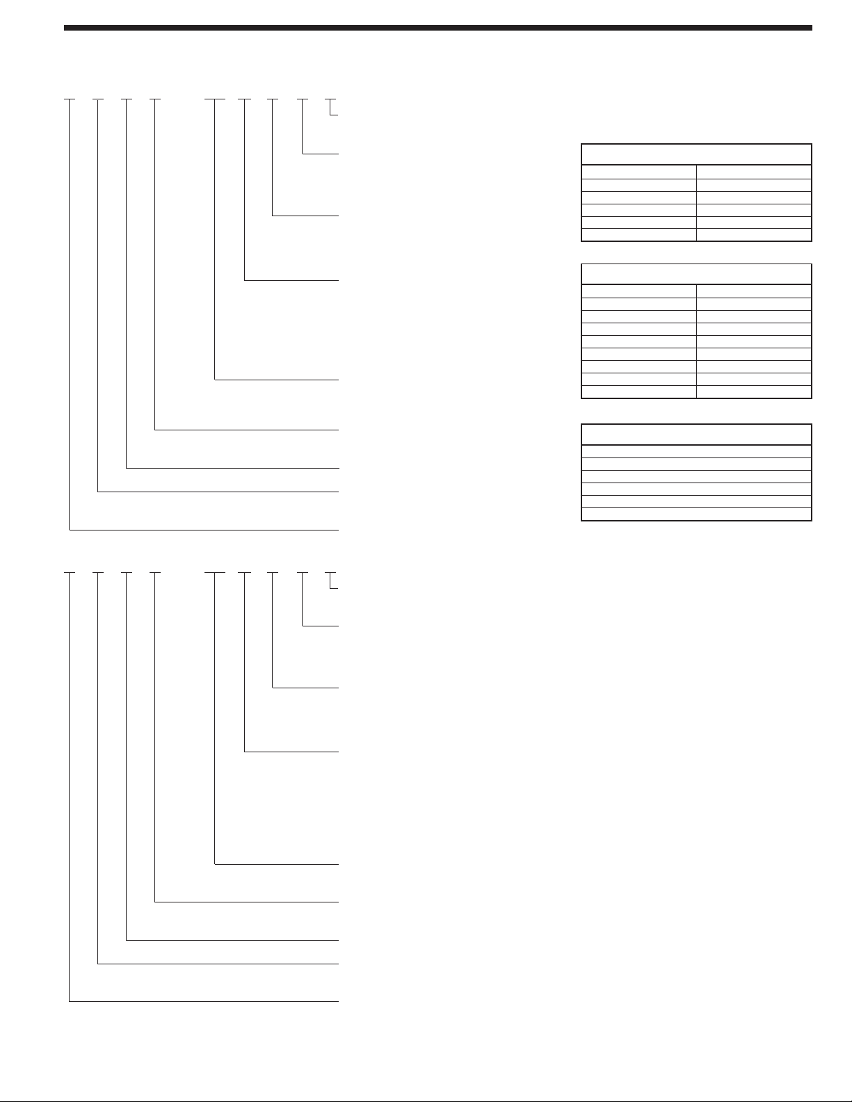
RHSL—HM1817JA
Design Variation
A = 1st Design
Voltage
A = 115/1/60
D = 480V-3-60
J = 208/240/1/60
Cabinet Size
17 = 17.5" [431.8 mm] (600-1200 CFM)
21 = 21" [533.4 mm] (1200-1600 CFM)
24 = 24.5" [609.6 mm] (1600-1800 CFM)
Capacity
18 = 18,000 BTU/H [5.27 kW]
24 = 24,000 BTU/H [7.03 kW]
30 = 30,000 BTU/H [8.79 kW]
36 = 36,000 BTU/H [10.55 kW]
42 = 42,000 BTU/H [12.31 kW]
48 = 48,000 BTU/H [14.06 kW]
60 = 60,000 BTU/H [17.58 kW]
HM = A/C or HP, Multi-Position
(Vertical Upflow/Horizontal Left is the factory configuration)
Refrigerant
L = R-410A
S = Standard Model (PSC Motor)
Classification
H = Air Handler
Rheem
[ ] Designates Metric Conversions
RHLL—HM2417J A
Design Variation
A = 1st Design
Voltage
A = 115/1/60
J = 208/240/1/60
D = 460/3/60
Cabinet Size
17 = 17.5" [431.8 mm] (600-1200 CFM)
21 = 21" [533.4 mm] (1400-1600 CFM)
24 = 24.5" [609.6 mm] (1600-1800 CFM)
Capacity
24 = 18,000/24,000 BTU/H [5.27/7.03 kW]
36 = 30,000/36,000 BTU/H [8.79/10.55 kW]
38 = 30,000/36,000/42,000 BTU/H
[8.79/10.55/12.31 kW]
48 = 42,000/48,000 BTU/H [12.31/14.06 kW]
60 = 60,000 BTU/H [17.58 kW]
HM = A/C or HP Multi-Position
(Vertical Upflow/Horizontal Left is the
factory configuration)
Refrigerant
L = R-410A
L = High Efficiency (X-13 (ECM) Motor)
Classification
H = Air Handler
Rheem
Model Identification
Available Models at 115V A Voltage
RHSL-HM1817AA
RHSL-HM2417AA
RHSL-HM3017AA
RHSL-HM3617AA
RHSL-HM4221AA
RHSL-HM4821AA
RHLL-HM2417AA
RHLL-HM3617AA
RHLL-HM4821AA
RHLL-HM4824AA
RHLL-HM6024AA
RHLL-HM3821AA
Available Models at D Voltage
RHSL-HM3617DA
RHSL-HM4221DA
RHSL-HM4821DA
RHSL-HM4824DA
RHLL-HM6024DA
RHSL-HM6024DA
Available Models at 218V J Voltage
RHSL-HM1817JA
RHSL-HM2417JA
RHSL-HM3017JA
RHSL-HM3617JA
RHSL-HM3621JA
RHSL-HM4221JA
RHSL-HM4821JA
RHSL-HM4824JA
RHSL-HM6024JA*
RHLL-HM2417JA
RHLL-HM3617JA
RHLL-HM4821JA
RHLL-HM4824JA
RHLL-HM6024JA
RHLL-HM3821JA
• Supply circuit protective devices may be fuses or
“HACR” type circuit breakers.
• Largest motor load is included in single circuit
and multiple circuit.
• If non-standard fuse size is specified, use the next
larger fuse size.
• J Voltage (230V) single-phase air handler is
designed to be used with single or three phase
230 volt power. In the case of connecting 3-phase
power to the air handler terminal block, bring
only two leads to the terminal block. Cap, insu-
late and fully secure the third lead.
• The air handlers are shipped from the factory with
the proper indoor coil installed, and cannot be
ordered without a coil.
• The air handlers do not have an internal filter
rack. An external filter rack or other means of
filtration is required.
4 Rheem Heating, Cooling and Water Heating
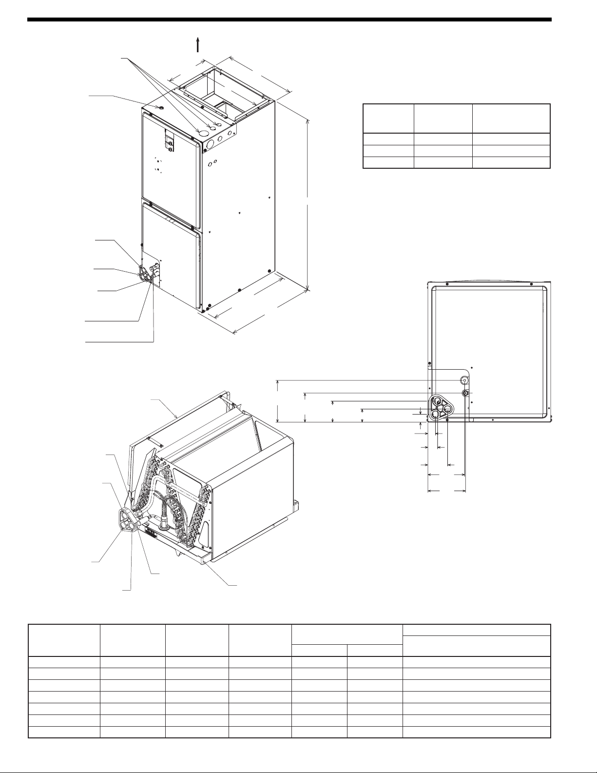
ELECTRICAL CONNECTIONS
MAY EXIT TOP OR EITHER SIDE
HIGH VOLTAGE CONNECTION
7
/8 [22.2 mm],
1
3
/32 [27.8 mm], 1
31
/32 [50 mm] DIA. KNOCKOUTS.
LOW VOLTAGE CONNECTION
5
/8 [15.9 mm] AND
7
/8 [22.2 mm] KNOCKOUT
VAPOR LINE CONNECTION
COPPER (SWEAT)
PRIMARY DRAIN CONNECTION
3
/4 [19.1 mm] FEMALE PIPE THREAD (NPT)
AUXILIARY DRAIN CONNECTION
3
/4 [19.1 mm] FEMALE PIPE THREAD (NPT)
UPFLOW/DOWNFLOW APPLICATION ONLY
LIQUID LINE CONNECTION
COPPER (SWEAT)
AUXILIARY DRAIN CONNECTION
3
/4 [19.1 mm] FEMALE PIPE THREAD (NPT)
HORIZONTAL APPLICATION ONLY
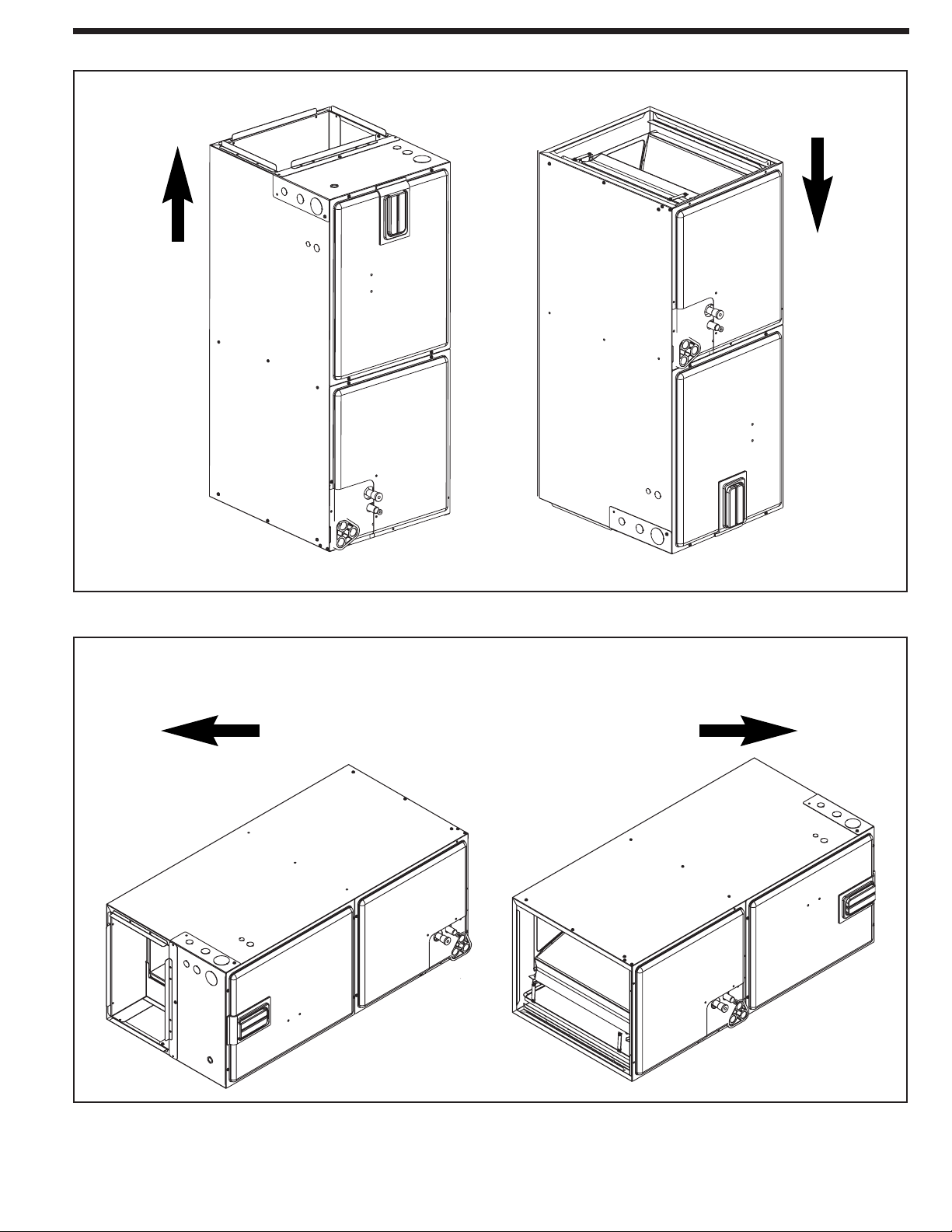
UPFLOW UNIT SHOWN:
UNIT MAY BE INSTALLED UPFLOW, DOWNFLOW,
HORIZONTAL RIGHT OR LEFT AIR SUPPLY.
NOTE: 24 CLEARANCE REQUIRED IN FRONT OF
UNIT FOR FILTER AND COIL MAINTENANCE.
A
W
H
19
1
/2 [495 mm]
RETURN AIR
OPENING
21
11
/16
[551 mm]
10
5
/16
[262 mm]
SUPPLY AIR
Model
Cabinet Size
Return Air
Opening Width
(Inches)
Return Air Opening
Depth/Length
(Inches)
17 15
7
/8 19
3
/4
21 19
3
/8 19
3
/4
24 22
7
/8 19
3
/4
Return Air Opening Dimensions
Unit Dimensions
[ ] Designates Metric Conversions
( ) Designates Unit with Double Coil Cabinet
Model
Size
RHLL & RHSL
Supply
Duct
“A” In. [mm]
Air Flow
CFM (Nom.) [L/s]
Unit Weight/Shipping Weight (Lbs.) [kg]
Unit With
Coil (Max. KW)
Lo Hi
1817/2417 16
1
/2 [406] 600 [283] 800 [378] 82/96 [37/44]
3017/3617
16
1
/2 [406]
1000 [472] 1200 [566] 92/106 [37/48]
3621 19
1
/2 [495] 1200 [566] — 97/112 [44/51]
4824
23
1
/2 [584]
1600 [755] — 162/180 [73/81]
6024
23
1
/2 [584]
— 1800 [850] 181/198 [82/90]
Unit
Width
“W” In. [mm]
24
1
/2 [622]
17
1
/2 [445]
17
1
/2 [445]
21
1
/2 [533]
24
1
/2 [622]
Unit
Height
“H” In. [mm]
55
1
/2 [1410]
42
1
/2 [1080]
42
1
/2 [1080]
42
1
/2 [1080]
55
1
/2 [1410]
21
1
/2 [533] 50
1
/2 [1282]
4221/4821
19
1
/2 [495]
1400 [661] 1600 [755] 150/166 [68/75]
3821 19
1
/2 [495] 1000 [472] 1200 [566] 150/166 [68/75]21
1
/2 [533] 50
1
/2 [1282]
Unit Dimensions & Weights
HORIZONTAL ADAPTER KIT
VAPOR LINE
CONNECTION
AUXILIARY HORIZONTAL
DRAIN CONNECTION
PRIMARY DRAIN
CONNECTION
AUXILIARY UPFLOW/DOWNFLOW
DRAIN CONNECTION
LIQUID LINE
CONNECTION
VERTICAL DRAIN PAN
5
15
/16
[151 mm]
4
1
/8
[105 mm]
3
1
/16
[76 mm]
1
3
/16 [48 mm]
1
1
/8 [29 mm]
1
1
/16
[27 mm]
1
3
/8
[35 mm]
2
13
/16
[71 mm]
5
1
/4
[133 mm]
5
3
/8
[136 mm]
Rheem Heating, Cooling and Water Heating 5
UPFLOW DOWNFLOW
Airflow Directions
HORIZONTAL RIGHT
HAND AIRFLOW
HORIZONTAL LEFT
HAND AIRFLOW
6 Rheem Heating, Cooling and Water Heating
Model Cabinet Size 17 17/21
Cooling BTUH x 1,000
Cooling Tons Nominal
-018
1.5
-024
2
-030
2.5
-036
3
-042
3.5
-048
4
-048
4
Heat Pump or Air Conditioning
Maximum Heat/Cool CFM [L/s]
(37.5 CFM [18 L/s]/1,000 BTUH)
(450 CFM [212 L/s]/Ton Nominal)
675
[319]
900
[425]
1125
[531]
1350
[637]
1575
[743]
1800
[850]
1800
[850]
Heat Pump or Air Conditioning
Nominal Heat/Cool CFM [L/s]
(33.3 CFM [16 L/s]/1,000 BTUH)
(400 CFM [189 L/s]/Ton Nominal)
600
[283]
800
[378]
1000
[472]
1200
[566]
1400
[661]
1600
[755]
1600
[755]
Heat Pump or Air Conditioning
Minimum Heat/Cool CFM [L/s]
(30.0 CFM [14 L/s]/1,200 BTUH)
(360 CFM [170 L/s]/Ton Nominal)
540
[255]
720
[340]
900
[425]
1080
[510]
1260
[595]
1440
[680]
1440
[680]
Maximum kW Electric Heating
& Minimum Electric Heat CFM [L/s]
13
487 [230]
13
617 [291]
18
814 [384]
18
1054 [497]
20
1171 [553]
25
1502 [709]
25
1502 [709]
Maximum Electric Heat Rise °F [°C] 80 [26.7] 63 [17.2] 66 [18.9] 51 [10.6] 49 [9.4] 50 [10] 50 [10]
24
-060
5
1930
[911]
1800
[850]
1620
[765]
30
1666 [786]
54 [12.2]52 [11.1]
18
1042 [492]
1080
[510]
1200
[566]
1350
[637]
-038
3.5
21
Airflow Performance
Airflow performance data is based on cooling performance
with a coil and no filter in place. Select performance table for
appropriate unit size, voltage and number of electric heaters to
be used. Make sure external static applied to unit allows opera-
tion within the minimum and maximum limits shown in table
below for both cooling and electric heat operation. For optimum
blower performance, operate the unit in the .3 [8 mm] to .7
inches [18 mm] W.C. external static range. Units with coils
should be applied with a minimum of .1 inch [3 mm] W.C.
external static range.
Airflow Operating Limits
[ ] Designates Metric Conversions
Rheem Heating, Cooling and Water Heating 7
External Static Pressure—Inches W.C. [kPa]
PSC CFM [L/s] Air Delivery/RPM/Watts—240 Volts
RPM 571
Blower Size/
Motor
HP [W]
# of Speed
626
Motor
Speed
from
Factory
687
Manufacturer
Recommended
Air-Flow Range
(Min/Max) CFM
Motor
Speed
736 791 — —
Watts 171 162 157 152 146 — —
10x6
1/5 HP [149]
2 Speed
High
CFM — — — — 661 [312] 612 [289] 564 [266]
RPM
0.1 [.02] 0.2 [.05] 0.3 [.07] 0.4 [.10] 0.5 [.12] 0.6 [.15] 0.7 [.17]
— — — — 837 878
RPM 541 596 657 706 761 — —
915
Watts 180 171 166 161 109 — —
10x6
1/5 HP [149]
2 Speed
High
240V
487/661 CFM
[230/312 L/s]
High
CFM — — — — 711 [336] 662 [312] 614 [290]
Low
CFM 638 [301] 607 [286] 565 [267] 530 [250]
RPM — — — — 812 853 890
487 [230] — —
Watts — — — — 232 216 199
RPM 616 667 715 770 808 — —
Watts 239 230 221 206 205 — —
10x6
1/5 HP [149]
2 Speed
High
CFM — — — — 888 [419] 828 [391] 774 [365]
RPM — — — — 875 908 958
High
240V
647/888 CFM
[305/419 L/s]
Low
CFM 817 [386] 779 [368] 757 [357] 693 [327] 647 [305] — —
Watts — — — — 331 313 301
RPM 646 697 745 800 838 — —
Watts 230 221 212 197 187 — —
10x6
1/5 HP [149]
2 Speed
High
CFM — — — — 838 [395] 778 [367] 724 [342]
RPM — — — — 900 933 983
High
240V
617/838 CFM
[291/395 L/s]
Low
CFM 787 [371] 749 [353] 727 [343] 663 [313] 617 [291] — —
Watts
— — — — 320 302 290
RPM 700 754 794 633 870 — —
Watts 344 313 302 309 288 — —
10x8
1/4 HP [186]
2 Speed
High
CFM — — — — 1004 [474] 951 [449] 883 [417]
RPM — — — —
High
240V
924
517/711 CFM
[244/336 L/s]
Low
CFM 668 [315] 637 [301] 595 [281] 560 [264] 517 [244] — —
953 975
Watts — — — — 243 227 210
High
240V
864/1004 CFM
[408/474 L/s]
Low
CFM 1022 [482] 987 [466] 940 [444] 903 [426] 864 [408] — —
Watts
— — — — 364 352 344
RPM 750 804 844 883 920 — —
Watts 324 293 282 274 268 — —
10x8
1/4 HP [186]
2 Speed
High
CFM — — — — 904 [427] 851 [402] 783 [370]
RPM — — — — 949 978 1000
High
240V
814/904 CFM
[384/427 L/s]
Low
CFM 972 [459] 937 [442] 890 [420] 853 [403] 814 [384] — —
Watts
— — — — 334 322 314
Model
No.
RHSL
-1817
with 13 kW
Heater
-2417
No Heater
-2417
with 13 kW
Heater
-1817
No Heater
-3017
No Heater
-3017
with 18 kW
Heater
-3617/-3621
No Heater
RPM 788 833 872 909 951 — —
Watts 466 462 427 406 395 — —
10x8
1/3 HP [249]
2 Speed
High
CFM — — — — 1248 [589] 1194 [563] 1133 [535]
RPM — — — — 1008 1028 1042
High
240V
1104/1248 CFM
[521/589 L/s]
Low
CFM 1229 [580] 1201 [567] 1170 [552] 1141 [538] 1104 [521] — —
Watts — — — — 488 475 454
240V Airflow Performance Data—RHSL (PSC Motor)
Notes: • All 208/240V PSC motors have voltage taps for 208 and 240 volts.
• All 208/240V PSC motors are shipped on high speed and 240 volts.
• If the application external static is less than 0.5" WC, adjust the motor speed to the low static speed as described below:
• Unplug the black motor wire off the relay on the control board and plug in the red motor wire.
• Replace the cap on the black motor wire.
• Voltage change (208/240V motors):
• Move the orange lead to transformer 208V tap from 240V tap. Replace the wire cap on 240V tap.
• Unplug the purple motor wire off the transformer and plug in the yellow motor wire.
• Replace the cap on the purple motor wire.
• The above airflow table lists the airflow information for air handlers without heater and air handler with maximum heater allowed for each model.
• The following formula can be used to calculate the approximate airflow, if a smaller (N kW) than the maximum heater kit is installed.
Approximate Airflow = Airflow without heater - (Airflow without heater - Airflow with maximum heater) x (N kW/maximum heater kW)
[ ] Designates Metric Conversions
8 Rheem Heating, Cooling and Water Heating
External Static Pressure—Inches W.C. [kPa]
PSC CFM [L/s] Air Delivery/RPM/Watts—240 Volts
RPM 834
Blower Size/
Motor
HP [W]
# of Speed
-6024
with 30 kW
Heater
870
Motor
Speed
from
Factory
902
Manufacturer
Recommended
Air-Flow Range
(Min/Max) CFM
Motor
Speed
948 968 — —
Watts 560 549 535 476 462 — —
10x10
1/2 HP [373]
2 Speed
High
CFM — — — — 1537 [725] 1418 [669] 1334 [630]
RPM
0.1 [.02] 0.2 [.05] 0.3 [.07] 0.4 [.10] 0.5 [.12] 0.6 [.15] 0.7 [.17]
— — — — 1072 1077
RPM 838 883 922 959 1001 — —
1085
Model
No.
RHSL
-4221
No Heater
-4221
with 20 kW
Heater
-4821/-4824
No Heater
-3617/3621
with 18 kW
Heater
Watts 446 442 407 386 375 — —
10x8
1/3 HP [249]
2 Speed
-4821/-4824
with 25 kW
Heater
RPM
High
240V
1241/1537 CFM
[586/725 L/s]
High
CFM — — — — 1148 [542] 1094 [516] 1033 [487]
Low
CFM 1526 [720] 1474 [696] 1427 [673] 1307 [617]
RPM — — — — 1033 1053 1067
1241 [586] — —
Watts — — — — 860 835 820
RPM 886 906
-6024
No Heater
925 959 992
839
— —
865 890 913
Watts 542 524 505 468 431 — —
10x10
1/2 HP [373]
2 Speed
High
CFM
935 —
— — — — 1437 [678] 1318 [622] 1234 [582]
RPM — — — — 1080 1090 1105
—
Watts 745 729 713 696 678
High
240V
1225/1500 CFM
[553/678 L/s]
Low
CFM 1456 [687] 1404 [663] 1357 [640] 1237 [584] 1171 [553] — —
Watts — — — — 840 800 785
RPM 878 920 950 981 1007 — —
Watts 785 757 707 667 641 — —
10x10
3/4 HP [559]
2 Speed
High
CFM — — — — 1824 [861] 1767 [834] 1653 [780]
RPM — — — — 1102 1112 1121
— —
11x11
3/4 HP [559]
2 Speed
High
CFM — —
High
240V
1572/1824 CFM
[742/861 L/s]
Low
CFM 1741 [822] 1719 [811] 1667 [787] 1628 [768] 1572 [742] — —
Watts
— — — — 871 830 770
RPM 945 965 995 1025 1050 — —
Watts 715 685 650 630 610 — —
10x10
3/4 HP [559]
2 Speed
High
CFM — — — — 1724 [814] 1667 [787] 1553 [733]
RPM — — —
—
—
High
240V
1116
1054/1148 CFM
[497/542 L/s]
Low
CFM 1179 [556] 1151 [543] 1120 [529] 1091 [515] 1054 [497] — —
1119 1130
— 1865 [880] 1808 [853] 1754 [828]
Watts — — — — 458 445 424
RPM — —
High
240V
1225/1500 CFM
[709/814 L/s]
Low
CFM 1671 [789] 1649 [778] 1597 [754] 1558 [735] 1502 [709] — —
Watts
— — — — 810 780 730
RPM 764 803 838 865 889 — —
Watts 779 763 747 729 708 — —
11x11
3/4 HP [559]
2 Speed
High
CFM — — — — 1965 [927] 1908 [900] 1854 [875]
RPM — — — — 943 967 977
— — 987 1001 1014
High
240V
1225/1500 CFM
[709/814 L/s]
High
240V
1766/1965 CFM
[833/927 L/s]
Low
CFM 1944 [917] 1912 [902] 1860 [878] 1813 [856] 1766 [833] — —
Watts
— — — — 828 799 795
Low
CFM 1844 [870] 1812 [855] 1760 [831] 1713 [808] 1666 [786] — —
Watts — — — — 788 766 744
240V Airflow Performance Data—RHSL (PSC Motor) (con’t.)
Notes: • All 208/240V PSC motors have voltage taps for 208 and 240 volts.
• All 208/240V PSC motors are shipped on high speed and 240 volts.
• If the application external static is less than 0.5" WC, adjust the motor speed to the low static speed as described below:
• Unplug the black motor wire off the relay on the control board and plug in the red motor wire.
• Replace the cap on the black motor wire.
• Voltage change (208/240V motors):
• Move the orange lead to transformer 208V tap from 240V tap. Replace the wire cap on 240V tap.
• Unplug the purple motor wire off the transformer and plug in the yellow motor wire.
• Replace the cap on the purple motor wire.
• The above airflow table lists the airflow information for air handlers without heater and air handler with maximum heater allowed for each model.
• The following formula can be used to calculate the approximate airflow, if a smaller (N kW) than the maximum heater kit is installed.
Approximate Airflow = Airflow without heater - (Airflow without heater - Airflow with maximum heater) x (N kW/maximum heater kW)
[ ] Designates Metric Conversions
 Loading...