

Page 1

1
Before you Drive
Driving Controls
Audio System
Maintenance
Emergency Information
1
2
2
3
3
4
4
5
5
6
Technical Data
6
7
Page 2
Introduction
Introduction© MG Rover Group Limited 2003All rights reserved. No part of this publication may be reproduced, stored in a retrieval system or transmitted in any form, electronic, mechanical, recording or other means without prior written permission from MG Rover Group Limited.Publication Part No. RCL 0524 LAN (3rd Edition)English01/2003As part of the MG Rover Group environmental policy, this publication is printed on paper made from chlorine free pulp .
THE OWNER'S HANDBOOK
This handbook describes all of the MG Rover models and standard
equipment specifications within the model range. Some of the
information, therefore, may not apply to your particular car.
For your convenience, the handbook is divided into subject or
activity-based sections. These are listed on the previous page and
are mostly self-explanatory. However, if you experience difficulty
in locating a specific item or piece of information, you should
consult the alphabetical index near the back of the book.
You should also be aware that the final (Service History) section of
this handbook is, in effect, a separate publication, which enables a
record to be kept of the routine services and inspections carried out
on the car. This section also provides a facility for the dealer to
record brake fluid and coolant changes, and the fitting of any major
replacement components needed during the life of the car.
Finally, always remember that if you have any queries, concerning
the operation or specification of your car, your MG Rover dealer
will be glad to advise you.
© MG Rover Group Limited 2003
All rights reserved. No part of this publication may be reproduced, stored
in a retrieval system or transmitted in any form, electronic, mechanical,
recording or other means without prior written permission from MG
Rover Group Limited.
Publication Part No. RCL 0548LAN
English 01/2003
As part of the MG Rover Group environmental policy, this publication is
printed on paper made from chlorine free pulp.
SYMBOLS USED
The following symbols used within the handbook call your
attention to specific types of information.
This warning symbol identifies procedures that must be
followed precisely, or information that must be considered with
great care, in order to reduce the risk of personal injury or serious
damage to the car.
This recycling symbol identifies those items that must be disposed of
safely in order to prevent unnecessary damage to the environment.
This symbol identifies those features that can be adjusted or disabled/
enabled by an MG Rover dealer
* An asterisk appearing within the text, identifies features or items
of equipment that are either optional, or are only fitted to some
vehicles in the model range.
STATUS AT TIME OF PRINTING
MG Rover operate a policy of constant product improvement and
therefore reserve the right to change specifications without notice
at any time. Whilst every effort is made to ensure complete
accuracy of the information in this handbook, no liabilities for
inaccuracies or the consequences thereof, including loss or damage
to property, or injury to persons, can be accepted by the
manufacturer or the dealer who supplied the handbook, except in
respect of personal injury caused by the negligence of the
manufacturer or dealer.
2
Page 3
Introduction
SECURITY CARD
The security card contains important emergency information. It is
ESSENTIAL that you keep the card safe from theft and ensure that
it is passed to the new owner if you sell the car.
• VIN (vehicle identification number): This number is unique to
your vehicle and is essential proof of its specification. The
number can also be found in various locations around the
vehicle (see ‘IDENTIFICATION NUMBERS’, page 212).
• Locking wheel nut number: If your vehicle has locking
wheel nuts, you will have been provided with a special wheel
nut adaptor to remove them. Quote this number if a
replacement adaptor is required.
• Radio serial number: This unique number is stamped into
the case of the audio unit, and is proof of the unit’s specification
and your ownership in the event of theft.
• Radio security code number: This unique code must be
entered into the radio whenever the power supply has been
disconnected. Without this code, the radio unit will not
operate.
Never leave the security card inside the car when it is left
unattended. Keep the card on your person in case of
emergencies.
IMPORTANT
When the time comes to sell your car, please remember to pass this
handbook and the Security Card to the new owner. Both must be
considered part of the car and essential to its operation.
IN AN EMERGENCY
IMPORTANT
Remember the breakdown safety code
If a breakdown occurs while travelling:
• Wherever possible, consistent with road safety and traffic
conditions, the car should be moved off the main thoroughfare,
preferably into a lay-by. If a breakdown occurs on a motorway,
pull well over to the inside of the hard shoulder.
• Switch on hazard lights.
• If possible, position a warning triangle or a flashing amber light at
an appropriate distance from the vehicle to warn other traffic of
the breakdown, (note the legal requirements of some countries).
• Consider evacuating passengers through nearside doors onto the
verge as a precaution in case your vehicle is accidentally struck by
other traffic.
3
Page 4

Page 5

1
Before you Drive
6 Controls
7 Locks & Alarm
17 Seats
21 Seat Belts
25 Child Restraints
27 Airbag SRS
33 Steering Column
34 Mirrors
36 Windows
37 Sunroof
38 Heating & Ventilation
46 Parking Heater
53 Interior Equipment
59 In-Car Telephones
60 Load Carrying - Saloon
62 Load Carrying - Tourer
69 Towing
1
Page 6
Before you Drive
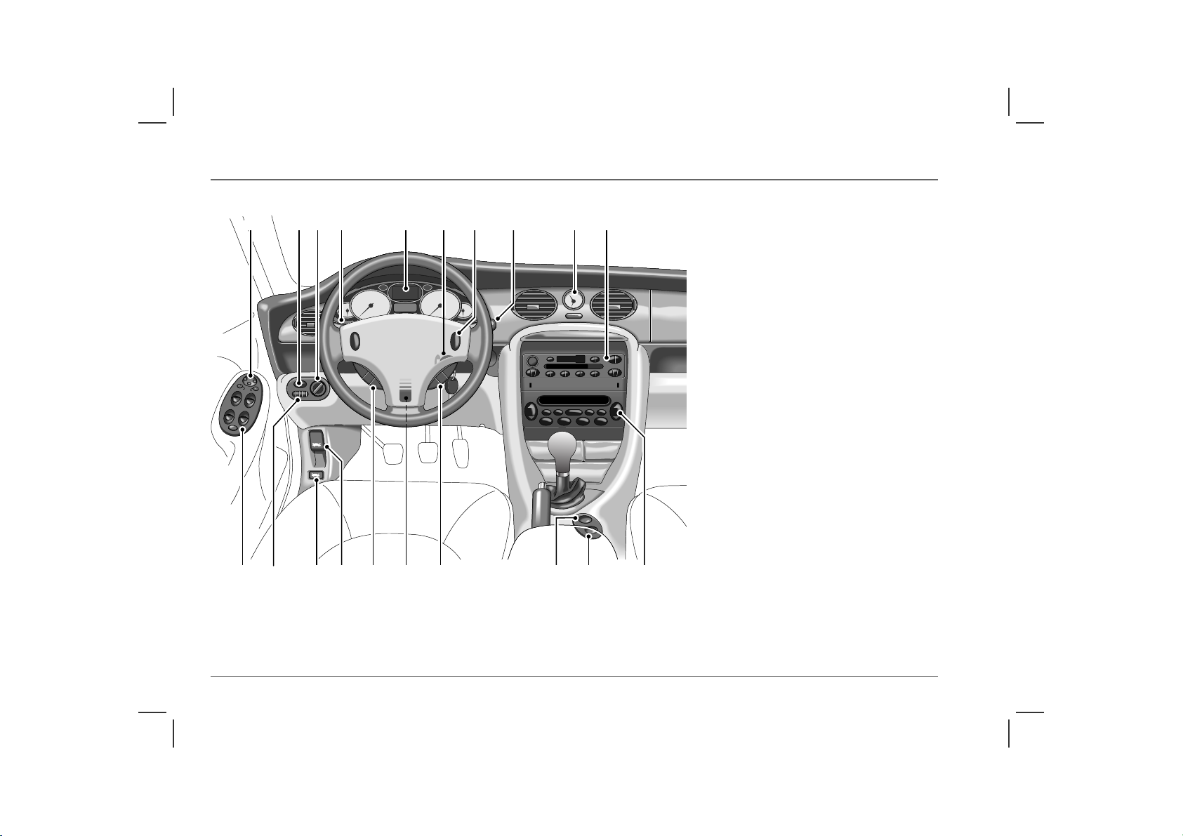
Controls
1 2 3 4 5 6 7
Controls
8 9 10
1. Mirror controls
2. Front
* and rear fog light switches
3. Main lighting switch
4. Direction indicators
5. Instrument panel
6. Starter switch
7. Horn
8. Wiper/washer controls
9. Clock
10. Heating/air conditioning controls
11. Audio system
12. Interior door locking switch
13. Hazard warning lights switch
14. Cruise control switches
*
15. Steering column adjustment lever
16. Remote audio controls
17. Bonnet release
18. Boot release (saloon models)
19. Instrument dimmer control
20. Electric window controls
HB0229b
6
1113 121415161720 1819
Page 7

Locks & Alarm
Locks & Alarm
KEYS AND HANDSETS
You have been supplied with two remote handsets with integral
keys which operate all locks.
Keep the spare handset key in a safe place - NOT IN THE
VEHICLE!
The keys supplied with your car are programmed to your security
system - they CANNOT be re-programmed and the engine
cannot be started without a key programmed to your car. If a key
is lost or broken, a replacement can only be ordered from an MG
Rover dealer.
NOTE: MG Rover dealers do not stock spare keys, time has to be
allowed for replaceme nts to be programmed to y our security system and then
delivered to the dealer.
If you lose a key, contact your MG Rover dealer; a key reported
lost will be deactivated. If the key is recovered, your dealer can
have it reactivated.
ALARM SYSTEM
Your car is fitted with a sophisticated electronic anti-theft alarm
and engine immobilisation system. There are also a number of
additional security features, some of which are selectable options.
In order to ensure maximum security and operating convenience,
you are strongly advised to gain a full understanding of the features
and alternatives available, by thoroughly reading this section of the
handbook.
NOTE: FOR MAXIMUM SECURITY ALWAYS
SUPERLOCK THE VEHICLE USING THE REMOTE
HANDSET (except when passengers are to be left inside the car).
ENGINE IMMOBILISATION
Engine immobilisation is an important aspect of the security
system, it is designed to safeguard the vehicle from theft, should
the driver forget to lock the doors and prevents the engine from
being started unless the GENUINE handset key is inserted into the
starter switch. Engine immobilisation is automatic whenever any
of the following conditions occur:
• Three seconds after the starter switch has been turned off.
• If the key is removed from the starter switch.
The engine will be re-mobilised automatically whenever
the genuine handset key is inserted into the starter switch
and turned to the first position.
1
7
Page 8
Locks & Alarm
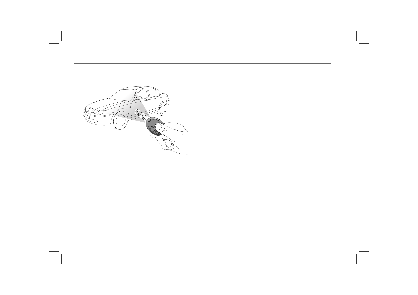
LOCKING THE CAR AND ARMING THE ALARM
Using the remote handset
H2698b
While it is not necessary to point the handset at the car, the handset
must be within range when the buttons are pressed. Note that the
operating range may vary depending upon handset battery
condition and may sometimes be limited by physical and
geographical factors beyond your control. From a security point of
view, it may not be wise to unlock unless you are close enough to
visually confirm that the doors have locked.
Locking
With the remote handset:
1. Shut the doors, bonnet and luggage compartment.
2. Press the lock (padlock symbol) button once:
• all doors are superlocked (see ‘Superlocking’, page 9)
• perimetric alarm activated (protects the doors, bonnet
and luggage compartment)
• interior space protection activated
3. The direction indicator lights flash three times to confirm that
the car is securely locked and the anti-theft alarm indicator
light (in the instrument panel) starts to flash.
With the key:
1. Insert the key and turn the door lock towards the rear of the
car:
• all doors locked (not superlocked)
• perimetric alarm activated (protects the doors, bonnet
and luggage compartment)
• NO INTERIOR SPACE PROTECTION
2. The direction indicator lights flash three times to confirm that
the car is securely locked and the anti-theft alarm indicator
light (in the instrument panel) starts to flash.
*
8
Page 9

Locks & Alarm
Superlocking
For safety, NEVER use Superlocking if passengers are to
remain inside the car - in an emergency they would not be able
to escape. Also, on cars fitted with interior space protection, any
movement from inside the car would activate the alarm.
Provided all the doors are fully closed, the superlocking feature is
activated automatically whenever the car is locked using the
remote handset. Superlocking immobilises the interior door
handles, thereby preventing an intruder from gaining entry by
smashing a window and reaching inside the car to operate the door
handles.
Mislock
If the driver's door is not fully closed when the handset lock button
is pressed, the alarm sounder or vehicle horn will sound once,
indicating a mislock. In this case, none of the doors will lock and
the alarm system will not be armed.
If a passenger door, bonnet or the luggage compartment is not fully
closed when the handset lock button is pressed, the alarm sounder
or vehicle horn will sound once, indicating a mislock. However,
the ‘partial arming’ attributes of the security system will enable as
much of the system to be armed as possible (all fully closed door,
bonnet or luggage compartment apertures will be protected, but
an open door will not!). As soon as the open aperture is closed, the
system will automatically revert to an armed state.
NOTE: If a mislock occurs as a result of an open door, the superlocking
and interior space protection features will not be activated, until the door is
closed and the locking process is repeated.
Anti-theft alarm indicator light
The light provides information about the status of the alarm
system, as follows:
• When the alarm is armed:
The light flashes RAPIDLY while the alarm is arming itself.
After ten seconds, the light adjusts to a slower frequency and
continues to flash as an anti-theft deterrent until the alarm is
disarmed.
• When the alarm is partially armed: (mislock)
The light flashes SLOWLY for 10 seconds, then flashes as an
anti-theft deterrent (as above) until the alarm is disarmed.
• When the alarm has been triggered:
If the light flashes after the car is unlocked, this indicates that
the alarm has been triggered during the driver’s absence. The
light will flash for up to one minute or until the starter switch
is turned on.
If the alarm sounds
If the alarm is triggered, the alarm sounder or vehicle horn will
sound for 30 seconds before switching off and resetting itself to the
same protection status that existed prior to the alarm being
triggered.To silence the alarm, press either button on the remote
handset, or lock/unlock the door using the key.
1
9
Page 10
Locks & Alarm
Unlocking
With the remote handset:
• Press the unlock button once. This will disarm the alarm and
unlock the driver's door only (see ‘Single point entry’).
• Press the unlock button twice to disarm the alarm and unlock
ALL the doors.
In either case, the direction indicator lights flash once and the
interior lights illuminate.
With the key:
• Turn the key in the driver's door lock towards the front of the
car to disarm the alarm and unlock the driver's door only (see
‘Single point entry’).
• Turn the key twice (or press the interior locking button), to
unlock ALL the doors.
Single point entry
This feature can be disabled by an MG Rover dealer.
This is a personal security feature, which enables the driver's door
alone to be unlocked, leaving the other doors in a locked state. It
can be operated by the remote handset as follows:
Press the unlock button once (or turn the key in the driver’s door
lock towards the front of the car) to unlock the driver’s door. Press
the unlock button (or turn the key) a second time to unlock the
remaining doors.
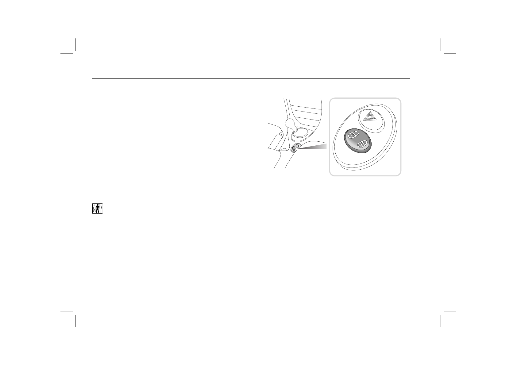
Interior locking switch
H2781a
This is a personal security feature which allows the driver to lock
(or unlock) all the doors from inside the car (while driving or with
the car stationary). Press the closed padlock symbol on the switch
to lock (the alarm will not be armed), and the open padlock
symbol to unlock.
NOTE: The locking switch will not operate the locks if the alarm has been
armed.
10
Page 11
Locks & Alarm
Interior door handles and door sill locking buttons
From inside the car, each door can be individually locked by
depressing the appropriate door sill button. However, doors
cannot be unlocked by raising the sill button.
Use the door handles to unlock, as follows:
1. First operation of the door handle unlocks the door.
2. Second operation of the door handle opens the door.
Speed-related locking
Speed related locking can be selected or deselected by an MG Rover
dealer.
This feature locks all the doors automatically when the road speed
exceeds 4 km/h and the boot or tailgate when speed has reached
10 km/h. Similarly, the door, boot (or tailgate) locks will unlock
automatically when the car has slowed to the same speeds.
This feature is not selectable by the driver, and operation of the
door locks by any other means (interior locking switch on the
centre console, for example) will disable the speed-related locking
function for the remainder of the journey, or until the starter
switch is turned off and on again.
*
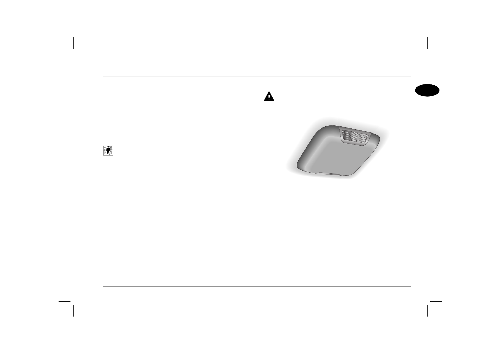
Interior space protection
Never activate interior space protection if passengers or
animals are to be left inside the car - any movement will
activate the alarm.
HB0494
Interior space protection (ultrasonics) is designed to protect the
interior of the car from intrusion (entry by a thief through a
smashed window, for example). Ultrasonic sensors, mounted on
the roof lining, monitor the interior space and activate the alarm if
air movement is detected in the passenger compartment.
NOTE: Interior space protection cannot be activated if a door, window or
sunroof is open, or if the starter switch is turned on.
Using the handset: Interior space protection is activated
automatically whenever the remote handset is used to set the
alarm.
Key operation: Using the key to set the alarm will NOT activate
interior space protection.
*
1
11
Page 12
Locks & Alarm
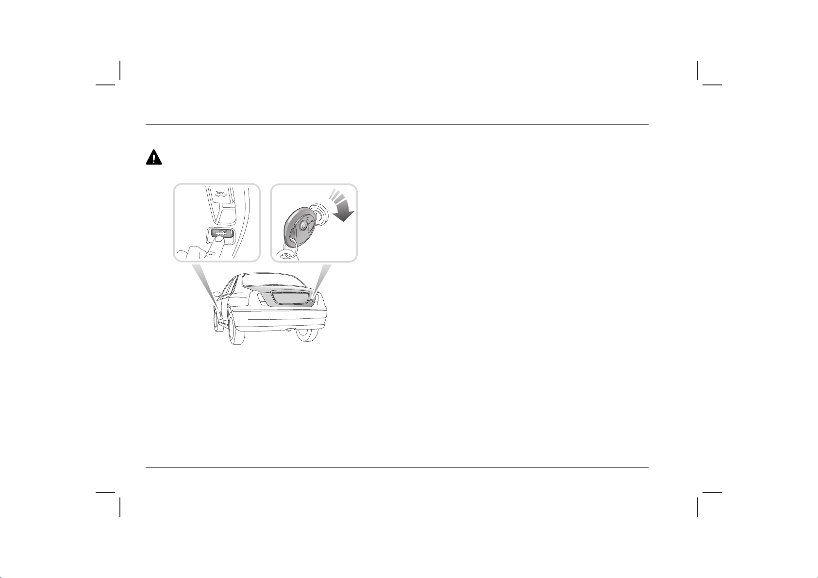
LUGGAGE COMPARTMENT (Saloon models)
Do not drive with the luggage compartment open, as poisonous
exhaust gases will enter the car.
HB0511
To open, turn the key clockwise in the lock or, from inside the
car, press the release button in the driver's footwell. The luggage
compartment and interior lights switch on automatically when the
boot lid is opened.
The luggage compartment is automatically locked when the boot
lid is closed.
NOTE: The interior release button is not operational when the alarm
system is armed.
For convenience, with the alarm system armed, the luggage
compartment can be unlocked and opened USING THE KEY,
without activating the alarm (the rest of the car will remain
protected and the engine immobilised during this process). The
alarm will automatically rearm as soon as the boot lid is closed.
12
Page 13
Locks & Alarm
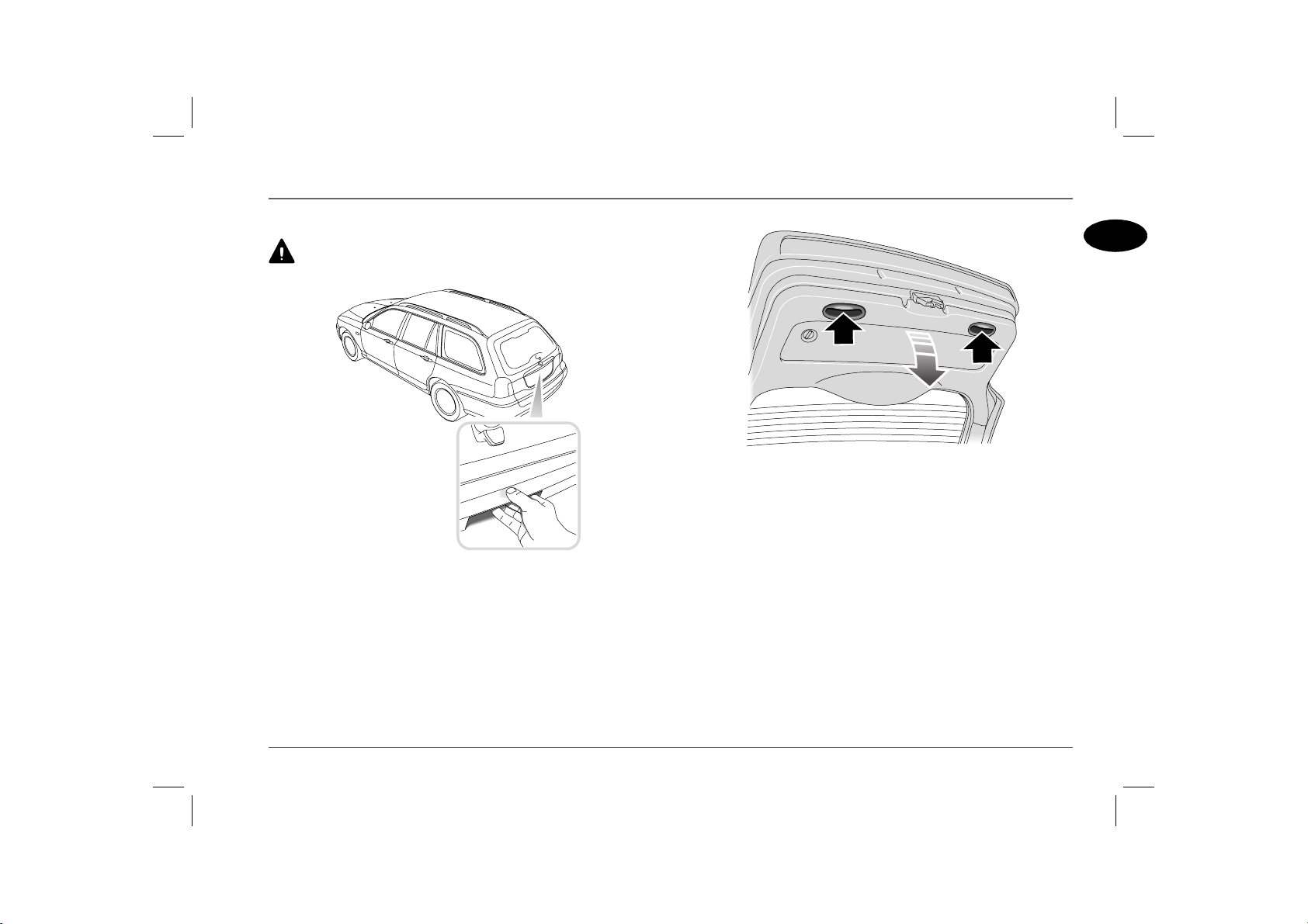
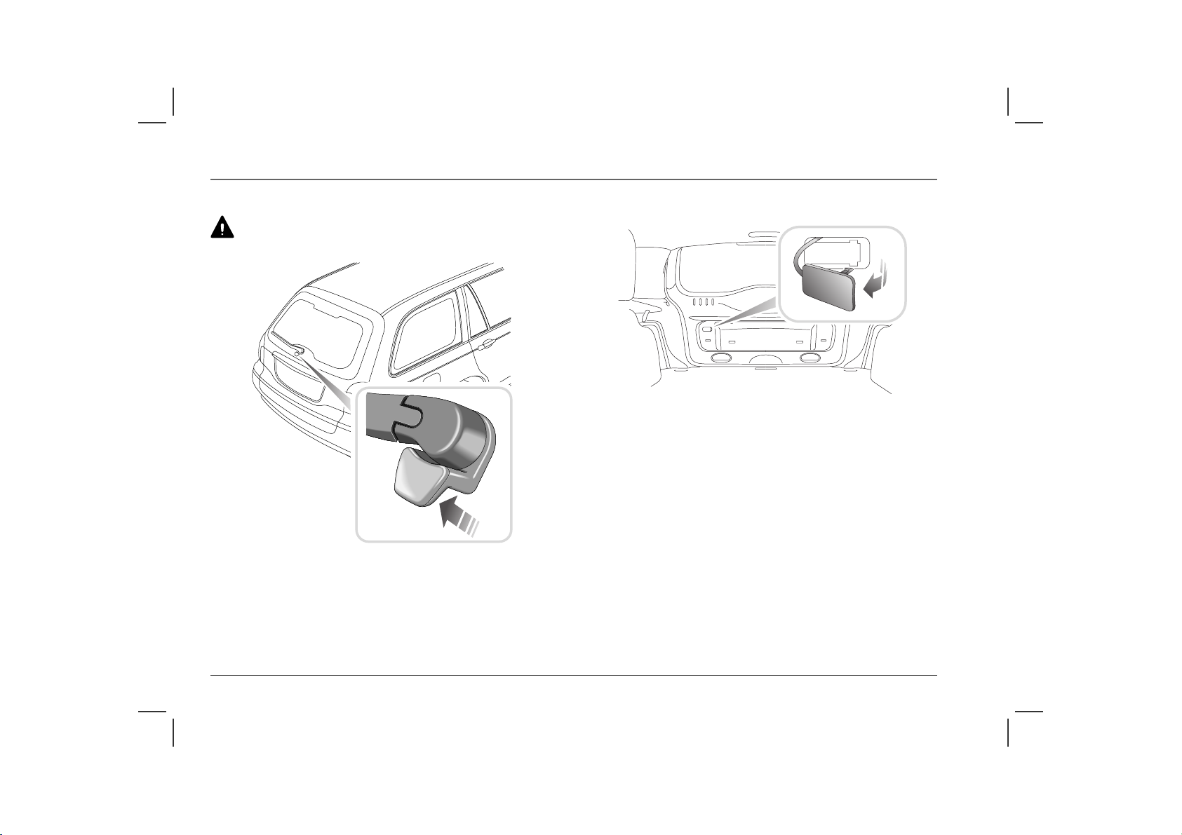
TAILGATE (Tourer models)
Do not drive with the tailgate open, as poisonous exhaust gases
will enter the car.
HB0510a
The tailgate and tailgate window are included in the car's central
locking system and lock/unlock automatically in tandem with the
doors.
To open the tailgate, the central door locking system must be
unlocked (press the unlock button on the handset twice, or turn
the door key to the unlock position twice). Operate the release
catch concealed in the underside of the tailgate trim applique
feature (see inset).
1
HB0037
When closing the tailgate, use the two hand grips set into the trim
panel on the inside of the tailgate (arrowed in illustration) to pull
the tailgate down. When the tailgate is partially closed, release the
hand grips and apply light downward pressure on the outside of the
tailgate below the number plate to close.
NOTE: The luggage compartment and interior lights illuminate
automatically when either the tailgate or tailgate window are opened.
NOTE: On cars equipped with speed-related locking, if the car has
stopped abruptly, and the starter switch is immediately turned off, the
speed-related locking control unit may not have had time to unlock the
tailgate - if this occurs, turn the starter switch on again for a few seconds
and then the tailgate can be opened as normal.
13
Page 14
Locks & Alarm
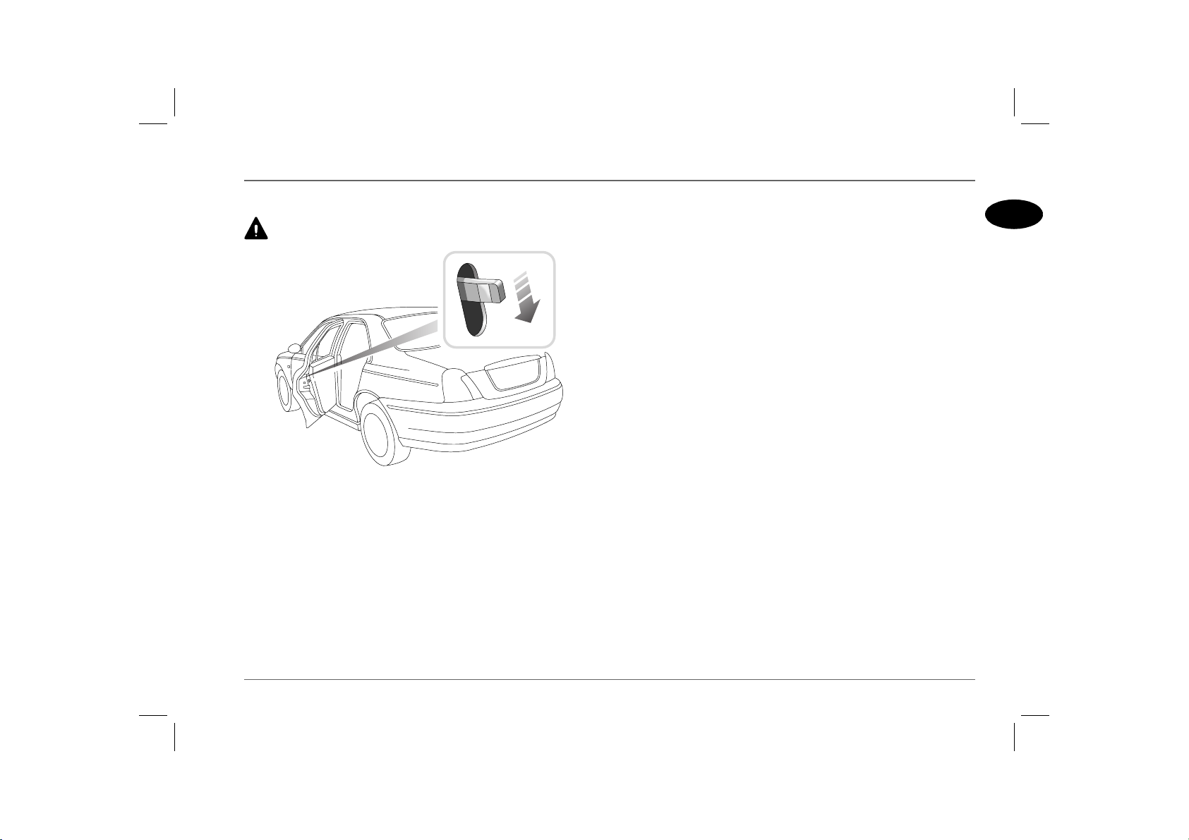
Tailgate window
Do not drive with the tailgate window open, as poisonous
exhaust gases will enter the car.
HB0031b
The tailgate window should only be opened when the tailgate is
closed. With the central door locking system unlocked (handset
unlock button pressed twice, or door key turned to the unlock
position twice), operate the switch concealed beneath the rear
wiper mounting to open (see illustration).
Tailgate emergency release
HB0500
If the battery is disconnected or discharged, the tailgate can be
opened manually as follows:
• Fold the rear seat cushion forward to gain access to the
loadspace.
• Remove the loadspace cover cassette, see‘LOADSPACE
COVER’, page 66.
• Twist the two turnbuckles a quarter turn anti-clockwise to
release the tailgate storage cover.
• Lever out plastic tab and pull to release the tailgate.
14
Page 15
Locks & Alarm
CHILD-PROOF LOCKS
NEVER leave children unsupervised in the car.
H2691
Move the locking levers on the rear doors down to engage the
child locks.
With the child-proof locks engaged, the rear doors cannot be
opened from inside the car, thereby avoiding the risk of a door
being opened accidentally while the car is moving.
1
15
Page 16
Locks & Alarm
REMOTE HANDSET BATTERY
The handset contains delicate electronic circuits and must be
protected from impact and water damage, high temperatures
and humidity, direct sunlight and the effects of solvents, waxes and
abrasive cleaners.
1
H2692a
The handset battery should last for approximately three years
dependent upon use. It is recommended that you fit an MG Rover
YWK10003 or a Panasonic CR2032 replacement battery.
When the battery needs replacing it will be apparent from a
gradual deterioration in range and performance.
On cars fitted with a message centre, a warning icon and message
will be displayed when the battery needs replacing (see ‘Handset
(key) battery low - RED’, page 87).
2
3
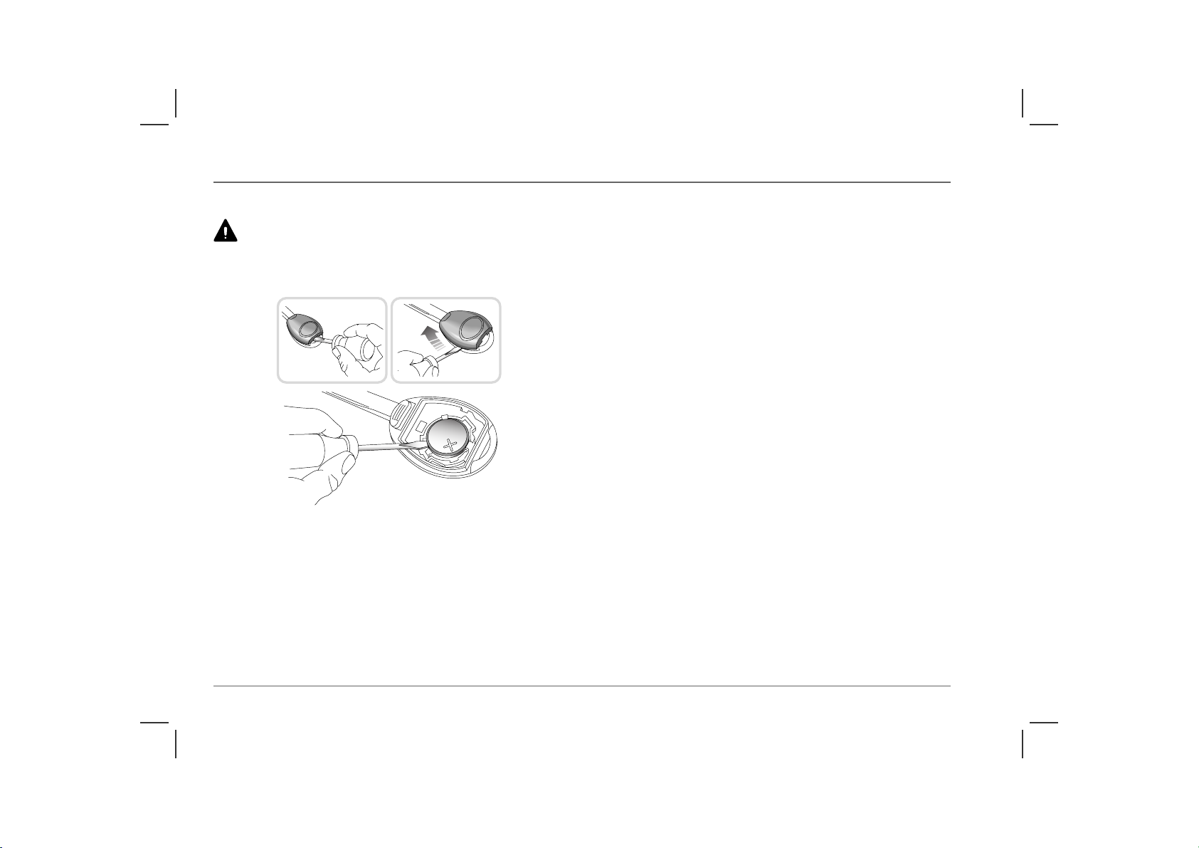
Battery replacement
1. Insert the blade of a small flat-bladed screwdriver into the slot
at the rear of the handset and prise the rear of the back
upwards.
2. Insert the screwdriver blade horizontally into the side of the
handset and then slide it towards the key. Lift off the back of
the handset.
3. Use the screwdriver to prise the battery from its mounting,
taking care to avoid touching the circuit board or the metal
battery contacts.
NOTE: Finger marks will adversely affect battery life; if possible,
avoid touching the flat surfaces of the battery and wipe them clean
before fitting.
4. Fit the new battery, ensuring that correct polarity is
maintained (‘+’ side facing up).
5. Press the two halves of the handset firmly together and ensure
that both halves are fully joined to prevent dirt or moisture
from entering the handset.
6. To resynchronise the handset, operate either button four
times in quick succession. On the fourth press the door should
lock or unlock, confirming resynchronisation.
The handset is now ready for use.
Handset re-synchronisation
If the handset fails to arm or disarm the alarm, this may be because
the coded signal transmitted by the handset, is no longer
synchronised with the receiver unit in the starter switch.
To re-synchronise the handset, hold the handset in close proximity
to the car and operate either handset button at least four times in
quick succession.
16
Page 17
Seats
CORRECT SEATING POSITION
To avoid the risk of loss of control and personal injury, DO
NOT adjust the seats while the car is moving.
The driver and front passenger seats should be positioned as far
rearward as practical. Ideally the seat should be positioned so that
the steering wheel can be held with the arms slightly bent and the
seat back in a nearly upright position.
Take care when adjusting the height of the driver's seat - a rear
seat passenger's feet might become trapped when lowering the
seat rearwards.
DO NOT allow front seat occupants to travel with the seat
backs reclined steeply rearwards. Optimum benefit is obtained
from the seat belt with the backrest angle set to approximately 25°
from the upright (vertical).
Head restraints are designed to restrain rearward movement of the
head in the event of an accident or sudden stop - a properly
adjusted head restraint can considerably reduce the risk of neck and
head injuries.
Make sure your driving position is comfortable and enables you to
maintain full control of the vehicle. A properly adjusted seat helps
reduce the risk of injury from sitting too close to an inflating
airbag.
Your car is fitted with side impact airbags. Refer to the Airbag
SRS section of this handbook before fitting seat covers, or
carrying out any repair or retrimming operations to the seat or seat
covers.
Seats
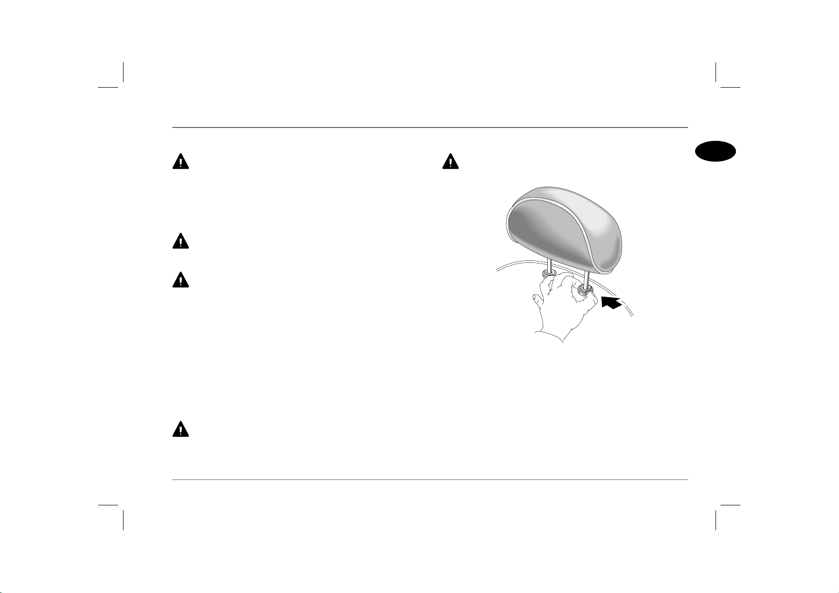
HEAD RESTRAINTS
Adjust the head restraint so that the cushion is level with the
back of the head - NOT THE NECK!
H3248
Raise or lower the restraint until the cushion is level with the back
of the head.
To lower the restraint, depress the button (arrowed) and push the
restraint downwards. To raise the restraint, pull the restraint
upwards without depressing the button.
On some models the angle of the restraint can be adjusted. Tilt the
restraint to ensure it is as close to the back of the head as possible.
To remove the head restraint, depress the button on the left hand
mounting and pull the restraint upwards.
1
17
Page 18
Seats
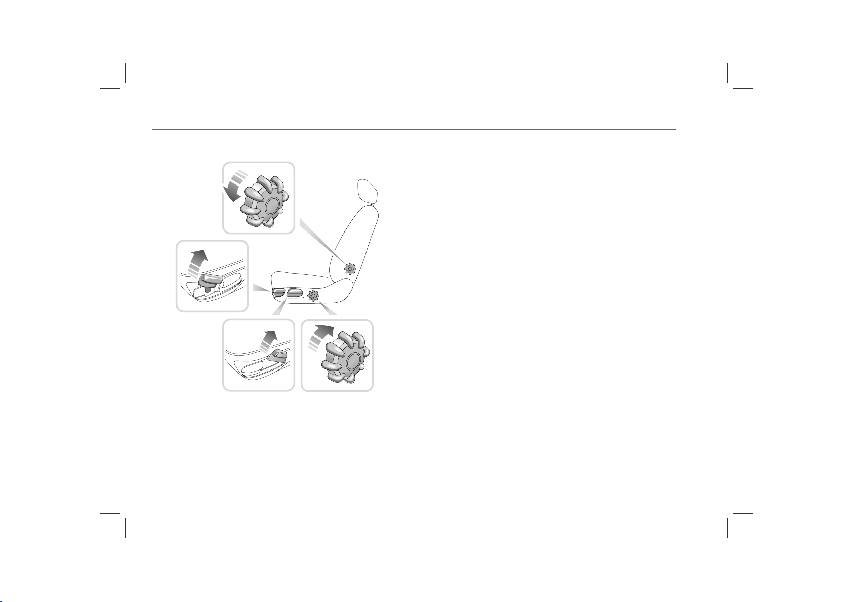
MANUALLY OPERATED FRONT SEATS*
4
1
2
HB0230
3
1. Forward/rearward adjustment
Lift the lever and slide the seat into position. Make sure the seat is
locked in position before driving.
2. Height adjustment (Driver's seat only)
Lift the lever and apply weight to lower the seat rearwards, or
allow the seat to rise forwards, as required.
3. Backrest adjustment
Rotate the handwheel to adjust.
4. Lumbar support adjustment
Rotate the handwheel to adjust.
*
18
Page 19
Seats
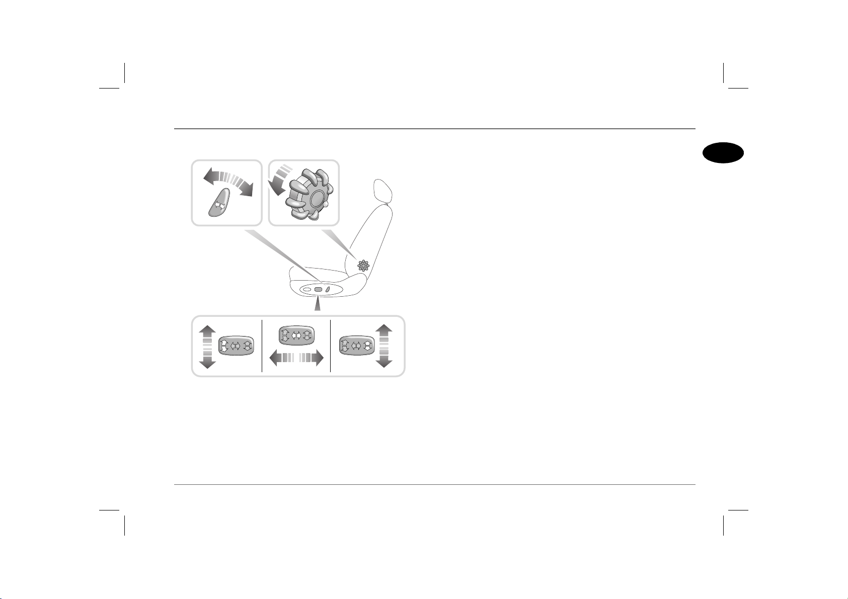
POWER-OPERATED FRONT SEATS*
54
2
HB0231
13
1. Forward/rearward adjustment
Push and hold the switch forwards or rearwards to move the seat.
2. Seat cushion angle (Driver's seat only)
Push the front of the switch up or down to tilt the seat cushion.
3. Seat cushion height (Driver's seat only)
Push the switch up or down to raise or lower the cushion.
4. Backrest adjustment
Twist the switch forward or backwards until the desired angle is
achieved.
5. Lumbar support
Rotate the handwheel to adjust.
Heated seats
For information on operating the heated front seats, see ‘Heated
seats*’, page 45.
*
1
19
Page 20
Seats
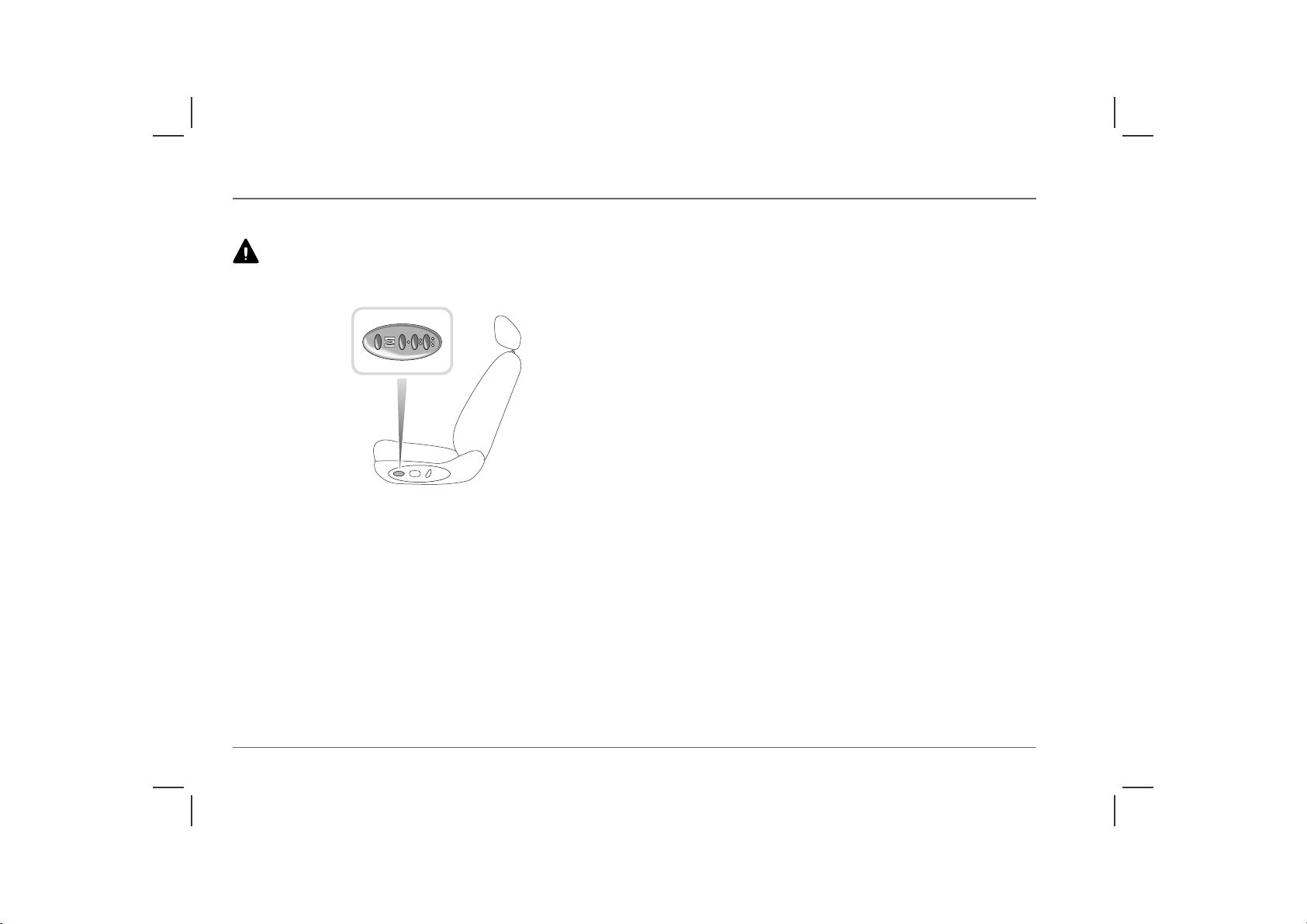
DRIVER'S SEAT MEMORY FACILITY*
Before activating the seat memory and lazy seat functions,
ensure that the area immediately surrounding the seat is clear
of obstructions and that all occupants are clear of moving parts.
H2826a
Your car can memorise three different driver seating positions. To
store the positions in the system memory, the starter switch must
be turned to the first or second position.
Adjust the seat to the required position and store the settings by
pressing and holding the memory store switch (‘M’) and, with the
memory store switch still depressed, press and release one of the
pre-set buttons (‘I’, ‘II’ or ‘III’). Finally, release the memory store
switch; a single chime will sound to confirm that the operation was
successful.
NOTE: If the car is in motion, the pre-set will need to be pressed and held
for the seat to move. This is to prevent inadvertent operation of the memory
pre-sets, which could cause the seat to move into a position in which the
driver is unable to drive safely.
To recall a stored position after the seat has been moved by another
driver, open the driver’s door and press the appropriate memory
pre-set button. The seat will return to the position stored by that
memory pre-set, a double chime will sound to confirm that the
operation is complete.
Lazy seats
The lazy seat facility enables the handsets to be used to recall seat
positions, when you unlock the doors.
Press and hold the handset unlock button to move the driver's seat
to the position stored in pre-set 1. An alternative driver's setting
can be programmed using pre-set 2. As before, position the seat
and programme pre-set 2 then, when the spare handset is used to
activate ‘Lazy seats’, the seat position stored in pre-set 2 will be
selected.
NOTE: Operation of the lazy seat facility will be cancelled if the driver’s
door is opened.
20
Page 21
Seat Belts
Seat Belts
SEAT BELT SAFETY
The seat belts fitted to your vehicle are intended for use by adult
sized occupants. Each belt should be used by one occupant only.
Observe the following precautions:
• DO make sure ALL passengers are securely strapped in at all
times - even for the shortest journeys.
• ALWAYS adjust seat belts to eliminate any slack in the
webbing. DO NOT slacken the webbing by holding the belt
away from the body - to be fully effective, the seat belt must
remain in full contact with the body at all times.
• ALWAYS fit the lap strap as low on the hips as possible (never
across the abdomen), and ensure that the diagonal belt passes
across the shoulder without slipping off or pressing on the neck.
• DO NOT wear seat belts over hard, sharp or fragile items in
clothing, such as pens, keys, spectacles etc.
• Always replace a seat belt assembly that has withstood the strain
of a severe vehicle impact, or if the webbing shows signs of
fraying.
• Where possible use the seat belts to secure large items of
luggage that are to be carried on the seats - in the event of an
accident, unsecured items become flying missiles capable of
causing serious injury.
• DO NOT use a seat belt that is twisted or obstructed in any
way that could impede its smooth operation.
• DO NOT allow front seat occupants to travel with the seat
backs reclined steeply rearwards. Optimum benefit is obtained
from the seat belt with the seat back angle set to approximately
25° from the upright (vertical) position.
• DO NOT allow foreign matter (particularly sugary food and
drink particles) to enter the seat belt locks - such substances can
render the locks inoperative.
• In most countries, all occupants are required by law to wear a
seat belt, unless they have been issued with a medical
exemption certificate.
• During pregnancy, women should wear the lap belt across the
hips below the baby, with the diagonal belt passing across the
shoulder, between the breasts and to one side of the baby - if in
doubt, consult a doctor.
The airbag supplementary restraint system (SRS) is designed
to add to the overall effectiveness of the seat belts. It does not
replace them. SEAT BELTS MUST ALWAYS BE WORN!
1
21
Page 22
Seat Belts
SEAT BELTS
Ensure that all seat belts are worn correctly - an improperly
worn seat belt increases th e risk of death or serious inj ury in the
event of a collision. Read the instructions below and the advice
contained under the heading ‘Seat belt safety’ on a previous page.
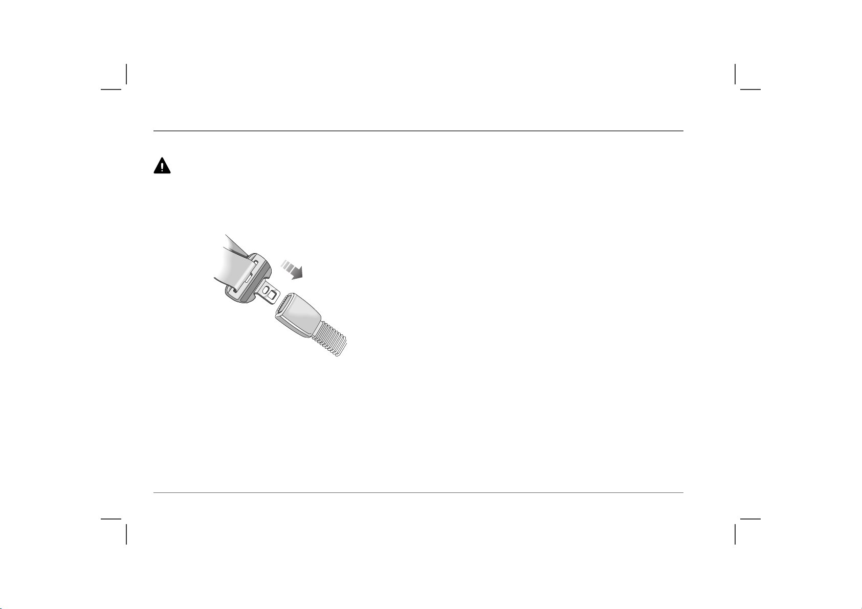
Fastening the belt
H2731
Pull the seat belt steadily over the shoulder and across the chest
and, ensuring the webbing is not twisted, insert the metal tongue
plate into the buckle nearest the wearer - a ‘click’ indicates that the
belt is securely locked.
NOTE: Where possible, rear seat passengers should adjust their position
to enable the seat belt webbing to cross the shoulder without pressing on the
neck.
Seat belts are designed to bear upon the bony structure of the body
(pelvis, chest and shoulders) and can only be worn safely with the
seats in a near-upright position; DO NOT allow the front
passenger to travel with the seat steeply reclined (see ‘Seating
positions’, page 28).
Releasing the belt
Press the red button on the seat belt buckle.
Upper anchorage height adjustment
To reduce the likelihood of injury in an accident, the height of the
front seat belt upper anchorage adjusts automatically as the seat is
moved either forwards or backwards. The height CANNOT BE
ADJUSTED MANUALLY!
22
Page 23

Seat Belts
SEAT BELT PRE-TENSIONERS
The seat belt pre-tensioners will only be activated once and
then MUST BE REPLACED by an MG Rover dealer.
Failure to replace the pre-tensioners will reduce the efficiency of the
car's front restraint systems.
The seat belt pre-tensioners activate in conjunction with the airbag
SRS to provide additional protection in the event of a severe
frontal, rear or side impact on the vehicle (see ‘HOW THE
AIRBAG SRS OPERATES’, page 29). The pre-tensioners
automatically retract the seat belts. This reduces any slack in both
the lap and diagonal portions of the belts, thereby reducing
forward movement of the belt wearer in the event of a severe
collision.
NOTE: The seat belt pre-tensioners will NOT be activated by minor
impacts.
The airbag SRS warning light on the instrument panel, will alert
you to any malfunction of the seat belt pre-tensioners (see ‘Airbag
SRS warning light’, page 31).
NOTE: After any impact, always have the seat belts and pre-tensioners
checked and, if necessary, replaced by an MG Rover dealer.
If the pre-tensioners have been activated, the seat belts will still
function as restraints, and must be worn in the event that the
vehicle remains in a driveable condition.
Disposing of vehicles
If you sell your car, be sure to inform the new owner that the
vehicle is fitted with pre-tensioners, and make the new owner
aware that the pre-tensioners must be examined and replaced by
qualified personnel after a period of 15 years.
If your car is to be scrapped, unactivated pre-tensioners are
potentially very dangerous and must be safely deployed in a
controlled environment by qualified personnel, before it is
scrapped.
1
23
Page 24

Seat Belts
CARING FOR SEAT BELTS
Always replace a seat belt assembly where the webbing shows
signs of fraying.
Regularly inspect the belt webbing for signs of fraying, cuts and
wear; also pay particular attention to the condition of the fixing
points and adjusters.
Do not bleach or dye the webbing and avoid contaminating the
webbing with polish, oil or chemicals (see ‘CLEANING THE
INTERIOR’, page 211).
Three tests for checking seat belts
1. With the seat belt fastened, give the webbing nearest the
buckle a quick pull - the buckle should remain securely
locked.
2. With the seat belt unfastened, unreel the webbing to the limit
of its travel. Check that unreeling is free from snags and
snatches and further check the webbing for visual signs of
wear or fraying.
Allow the webbing to retract, checking that retraction is
smooth, continuous and complete.
3. With the webbing half unreeled, hold the tongue plate and
give it a quick forward pull - the mechanism must lock
automatically and prevent any further unreeling.
If a seat belt should fail any of these tests, contact your dealer
immediately.
24
Page 25
Child Restraints
Child Restraints
CHILD SEATS
Children are more likely to receive injuries from inflating airbags
than taller occupants (see ‘AIRBAG SUPPLEMENTARY
RESTRAINT SYSTEM (SRS)’, page 27). For this reason, it is
recommended that children should always be seated in the rear of
the vehicle, in a child safety seat or restraint system appropriate to
their age and size. A table on the following page outlines the
seating positions suitable for use with a child safety seat or restraint
system. The range of safety seats approved for use in your car is
listed in the MG Rover accessories brochure, which is available
from your MG Rover dealer.
For optimum protection, it is recommended that children
weighing up to 13 kg (or approximately 18 months of age) are
restrained in an MG Rover-approved rear facing child seat in an
outer rear seating position.
All infant and child restraint systems are designed to be secured in
the car by means of a standard seat belt.
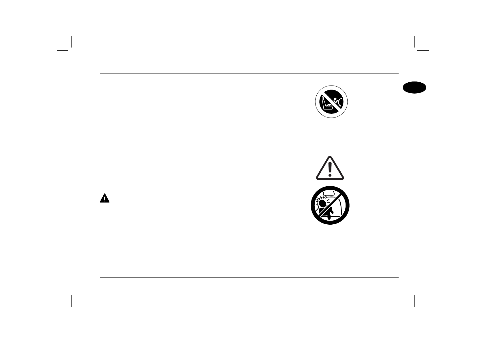
DO NOT install a rearward facing child seat in the front
passenger seat - an inflating airbag could impact with the seat.
Failure to follow this advice could result in serious injury, or even
death for the child.
When installing and using any infant or child restraint system,
always follow the manufacturer's instructions. Failure to properly
secure the child restraint system can endanger the child in a
collision or sudden stop and cause injury to other passengers.
B
A
R
G
I
A
HB0233
The above symbol affixed to the fascia panel of your car, warns
against the use of a REAR FACING child seat in the front
passenger seat. This type of child seat could cause serious injury to
your child in the event of an airbag deployment.
I
R
A
B
A
E
G
D
I
S
HB0235
If it is necessary for a child to travel in the front, it is essential that
the vehicle seat is set fully rearwards and that the child is seated in
a FRONT FACING child safety seat, which prevents any part of
the child’s head coming into close proximity with the side airbag
(note the warning label shown above).
1
25
Page 26
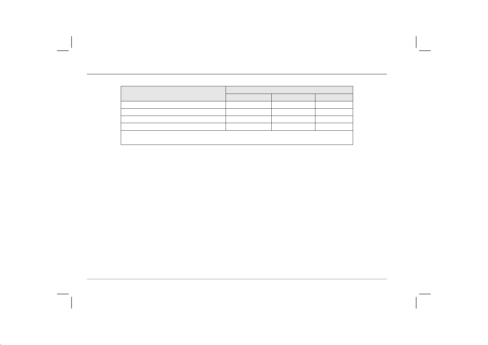
Child restraint seating options
Mass Group Seating Positions
(As indicated on child safety seat packaging)
0 = Up to 10 kg (0 - 9 months) X U U
0+ = Up to 13 kg (0 - 18 months) X U U
I = 9 to 18 kg (9 months - 4 years) X U U
II & III = 15 to 36 kg (4 - 12 years) X U X
U = Suitable for ‘Universal’ category restraints approved for this mass group.
X = Seat position NOT suitable for children of this mass group.
Child Restraints
Front Passenger Rear Outboard Rear Centre
26
Page 27
Airbag SRS
Airbag SRS
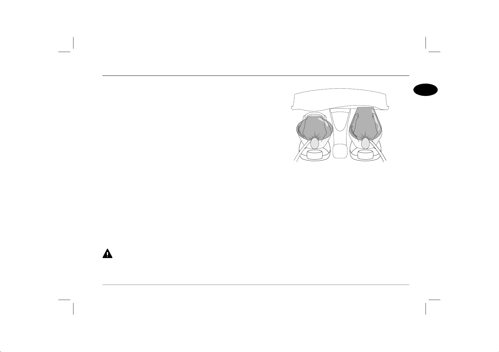
AIRBAG SUPPLEMENTARY RESTRAINT SYSTEM (SRS)
The airbag SRS provides ADDITIONAL protection in a
severe impact only. It does not replace the need to wear a seat
belt.
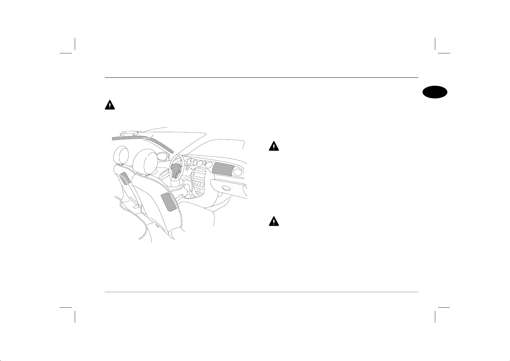
H2797b
The airbag SRS incorporates front and side airbags for both the
driver and front seat passenger.
NOTE: Inflation and deflation of the front and side airbags takes place
very quickly and will not protect against the effects of secondary impacts that
may occur.
Provided the front seat occupants are correctly seated, with seat
belts properly worn, the airbags will provide additional protection
to the chest and facial areas in the event of the car receiving a
severe frontal impact, and to the side of the body facing the impact,
if a severe side collision occurs.
Side head impact protection (where fitted) will afford additional
protection to the side of the head facing the impact, in the event
of a severe side collision.
Do not allow a front seat passenger to obstruct the operation of
the airbag by placing feet, knees or any other part of the person,
or any other objects in contact with, or in close proximity to, an
airbag module.
The front airbags are located in the centre pad of the steering
wheel and in the fascia panel above the glovebox. Side airbags are
positioned in the backrest padding on the outward side of both
front seats. The side head impact protection airbags (if fitted) are
situated behind the roof lining and front pillar finishers (where
shown).
DO NOT attach or position items on, or close to the roof
lining or front pillar and ‘B’ post finishers, or to an airbag
cover (steering wheel centre pad or fascia panel), which could
interfere with the inflation of the airbag or, if the airbag inflates, be
propelled inside the car causing injury to the occupants.
1
27
Page 28
Airbag SRS
Airbag deployment
To ensure correct deployment of the airbags, it is essential that
obstructions are not allowed to intervene between an airbag and
the occupant. The following are examples of the type of
obstructions that could either, impede correct operation of the
airbags, or jeopardise personal safety in the event of an airbag
deployment:
• Accessories attached to or obscuring an airbag cover, including
the roof lining, front pillar and ‘B’ post finishers and the part of
the front seat containing the side airbag or the pillar between
front and rear doors.
• Items of hand luggage, or other objects placed on an airbag
cover.
• Feet, knees or any other part of the anatomy in contact with,
or in close proximity to, a front airbag cover.
• Items on the shelf below the front passenger airbag that are
likely to impede airbag operation in the event of an impact.
• Head, arms or any part of the anatomy in contact with, or in
close proximity to, a side airbag.
• Items of clothing or cushions draped over the part of the front
seat containing the airbag or hanging from the grab handle
attached to the roof.
• Non-approved seat covers fitted over a front seat (in particular,
be aware that seat covers approved for other cars will NOT be
suitable for this car). If in doubt, seek advice from an MG
Rover dealer.
Seating positions
To minimise the risk of accidental injury from inflating
airbags, seat belts should be correctly worn at all times. In
addition, both driver and front seat passenger should adjust their
seat to provide the maximum practical distance from the front
airbags, and also ensure that a gap is maintained between the upper
torso and the side of the vehicle, to enable unobstructed inflation of
the side airbags.
In order to provide optimum protection in the event of a severe
impact, it is necessary for the airbags to deploy with considerable
speed.
An inflating airbag can cause facial abrasions and other injuries if
the occupant is too close to the airbag at the time of its
deployment.
28
Page 29
Airbag SRS
HOW THE AIRBAG SRS OPERATES
In the event of a collision, the airbag control unit monitors the rate
of deceleration or acceleration induced by the collision, to
determine whether the airbags should be deployed.
NOTE: The airbag SRS is not designed to operate as a result of rear
collisions, minor frontal or side impacts, or if the car overturns; nor will it
operate as a result of heavy braking or driving over bumps and potholes.
Operation of the airbag SRS is dependent entirely on the rate at
which the car's passenger compartment changes speed as a result of
a collision. The circumstances affecting different collisions (vehicle
speed, angle of impact, type and size of object hit, for example),
vary considerably and will affect the rate of acceleration or
deceleration accordingly.
It follows, therefore, that significant superficial damage can occur
without the airbags deploying or, conversely, that a relatively small
amount of structural damage may cause the airbags to be deployed.
In the case of a severe frontal collision, both front airbags will be
deployed. In the case of a severe side collision, only the side airbag
and side head impact protection airbag on the impact side of the
vehicle will inflate. However, there may also be impact conditions
whereby one set of side and both front airbags deploy at the same
time, or where front and side airbags respond separately as a result
of a secondary impact occurring after the initial collision has taken
place.
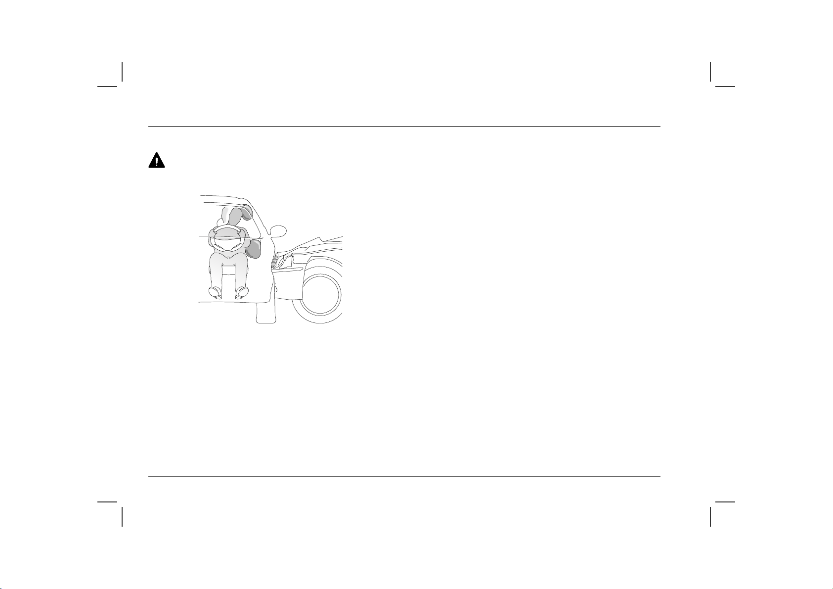
An inflating airbag can cause facial abrasions and other
injuries. Minimise the risk of injury by ensuring that front seat
occupants are wearing their seat belts and are seated correctly, with
the seat as far back as is practical.
1
H2798a
Airbag inflation is virtually instantaneous and occurs with
considerable force, accompanied by a loud noise. The inflated bag,
together with the seat belt restraint system, limit the movement of
a front seat occupant, thereby reducing the risk of injury to the
head and upper torso.
NOTE: After inflation, some airbag components are hot - DO NOT
touch until they have cooled.
When an airbag inflates, a fine powder is released. This is not an
indication of a malfunction, however, the powder may cause
irritation to the skin and should be thoroughly flushed from the
eyes and any cuts or abrasions of the skin. After inflation, front and
side airbags deflate immediately (side head protection airbags
deflate slowly). This provides a gradual cushioning effect for the
occupant and also ensures that the driver's forward vision is not
obscured.
29
Page 30
Airbag SRS
Side airbags
Ensure that a gap is maintained between the upper torso and
the side of the vehicle, to enable unobstructed inflation of the
side airbags.
H2799b
Side airbags are designed to protect the thorax region of the torso
and will only deploy in the event of a severe side impact. They will
NOT inflate as a result of frontal or rear impacts only.
In the event of a severe side collision, the airbag on the impact side
of the car breaks through the seat covering, rapidly inflating to
form a cushion between the occupant and the side of the car. The
airbag on the non-impact side of the car will not be deployed
Note that a part of the outer side of the seat trim (identified by the
woven ‘airbag’ label) is specially constructed to enable the airbag
to deploy.
NOTE: The manufacture and materials of the seat are critical to the
performance of the airbag. For this reason, non-approved seat covers must
NEVER be fitted, and it is recommended that any repair or replacement
to the front seats be carried out by an MG Rover dealer (see ‘SERVICE
INFORMATION’, page 32).
30
Page 31

Airbag SRS
Side head impact protection*
NOTE: For the side head impact airbags to deploy correctly, the roof
lining and front pillar trim must be undamaged and fitted correctly. Any
damage or suspect fitting should be referred to an MG Rover dealer for
examination.
Side head impact airbags are designed to protect the head in the
event of a severe side impact only. They will NOT inflate as a
result of frontal or rear impacts alone.
The side head impact protection modules are located behind the
roof lining and front pillar finisher, above the doors. In the event
of a severe side collision, the airbag pushes out from behind the
roof lining and front pillar finisher as it inflates. The side head
impact airbag remains inflated for longer than the other airbags, to
provide additional head protection in the event of a secondary
impact.
Airbag SRS warning light
A warning light, mounted on the instrument panel, will alert you
to any malfunction of the airbag SRS and seat belt pre-tensioners.
The light will illuminate as a bulb and system check when the
starter switch is turned to the second position and will extinguish
after approximately four seconds. The system should always be
checked by a dealer if any of the following symptoms occur:
• The warning light fails to illuminate when the starter switch is
turned to the second position.
• The warning light fails to extinguish within approximately four
seconds after the starter switch is turned to the second position.
• The warning light illuminates while the car is being driven.
1
31
Page 32

Airbag SRS
SERVICE INFORMATION
After 15 years from the initial date of registration (or installation
date of a replacement airbag SRS), some components will need to
be replaced by an MG Rover dealer, who should stamp and sign
the appropriate page of the Service History section of this book
once the work has been completed.
In addition, ALWAYS contact your dealer if;
• an airbag inflates.
• the front or side of the vehicle is damaged (even if the
corresponding airbag has not inflated).
• any part of an airbag module covers show signs of deterioration
or damage.
The components of the airbag SRS are sensitive to electrical and
physical interference; it is recommended that you ALWAYS seek
the assistance of an MG Rover dealer to carry out any of the
following:
• Removal or repair of any wiring or component in the vicinity
of the airbag SRS components, including: the steering wheel,
steering column, front seats, fascia and instrument panel.
• Installation of electronic equipment such as a mobile phone,
two-way radio or in-car entertainment system.
• Attachment of accessories to, or modification of, the front or
side of the vehicle.
• Removal, replacement, or retrimming of a front seat or seat
cover.
Disposing of the vehicle
If you sell your vehicle, be sure to inform the new owner that the
vehicle has an airbag SRS and make the new owner aware of the
airbag module replacement date.
If the vehicle is to be scrapped; uninflated airbags are potentially
very dangerous and must be safely deployed in a controlled
environment by qualified personnel, before a vehicle is scrapped.
DO NOT service, repair, replace, modify or tamper with any
part of the airbag SRS, or wiring in the vicinity of an airbag
SRS component; this could cause the system to activate, resulting in
personal injury.
32
Page 33

Steering Column
Steering Column
STEERING COLUMN ADJUSTMENT
DO NOT attempt to adjust the height or angle of the steering
wheel while the car is in motion. This is extremely dangerous.
H2674a
Adjust the angle and height of the steering column to suit your
driving position:
1. Fully release the locking lever.
2. Hold the steering wheel in both hands and tilt the steering
column up or down to move the wheel into the most
comfortable position.
NOTE: If it is difficult to move the steering column into a new
position, disengage the steering lock by turning the starter switch to
the first position and align the front wheels straight ahead.
3. Pull or push the steering wheel closer to, or further away
from, your body.
4. Once a comfortable driving position has been selected, pull
the locking lever fully up to lock the steering column into its
new position.
1
33
Page 34

Mirrors
Mirrors
POWER-OPERATED DOOR MIRRORS
NOTE: Objects viewed in exterior mirrors may appear further away than
they actually are.
2
1 1
3
H3279
Mirror glass adjustment
• With the starter switch turned on (first position), press the
appropriate switch (1) to select the left or right mirror.
• Use switch (2) to tilt the mirror glass up/down/left or right.
Heating elements
The door mirrors have integral heating elements which disperse
ice or mist from the glass. The heating elements operate
continuously while the starter switch is in the second position.
Mirror folding
*
The body of each door mirror is designed to fold flat against the
side of the car on impact. The mirrors can also be folded back
manually towards the side windows into a ‘park’ position to enable
the car to negotiate narrow openings.
HB0509
On some cars the ‘park’ position can be achieved electrically, as
follows:
With the starter switch turned on, press the mirror fold switch (3);
both mirrors will fold back towards the side window. Press the
switch a second time to return the mirrors to their normal position.
If one mirror is accidentally knocked out of position, a single press
of the switch will resynchronise both.
NOTE: The mirror fold switch can also be operated for up to 40 seconds
after the starter switch has been turned off.
34
Page 35

Mirrors
INTERIOR REAR-VIEW MIRROR
Adjust the body of the mirror by hand to achieve the best possible
view to the rear. The dipping function of both the automatic and
manual mirrors helps to reduce glare from the headlights of
following vehicles at night.
Automatic mirror
The interior mirror is equipped with a light sensor (arrowed)
which activates the automatic dipping function.
Manual mirror
Move the lever at the base of the mirror forward to ‘dip’ the
mirror. Normal visibility is restored by pulling the lever back
again.
NOTE: In some circumstances, the view reflected in a ‘dipped’ manual
mirror can confuse the driver as to the precise location of following vehicles.
Remember to take additional care!
*
H2829
*
VANITY MIRROR
The driver’s vanity mirror* should only be used when the car
is stationary
H2936a
Pivot the sun visor downward to use the vanity mirror. On some
models, the vanity mirror has a cover and is illuminated when the
cover is raised. Close the cover to extinguish the lights.
1
35
Page 36

Windows
POWER-OPERATED WINDOW CONTROLS
Accidental closing of a power-operated window on fingers,
hands or on any other vulnerable parts of the body can result in
serious injury.
1
2
Windows
Operating the windows
The electric windows can be operated when the starter switch is
in the first or second position and for up to 40 seconds after the
starter switch is turned off (provided neither front door is opened
in the meantime).
Push the switch down to lower, and lift the switch up to raise the
window. The window will stop moving as soon as the switch is
released (unless the ‘one-touch’ feature is active).
ENSURE children are kept clear when raising or lowering a
window.
34
H2809
5
Driver's door console
The switches on the driver's door operate the following:
1. Left hand front window.
2. Right hand front window.
3. Right hand rear window
4. Left hand rear window
5. Rear window isolation switch
*.
*.
*.
NOTE: The front and rear passenger windows can also be operated by
individual window switches, mounted on each door. The rear window
switches will not operate if the isolation switch has been activated.
36
Rear window isolation switch
*
Press the switch to isolate the rear window controls (an indicator
light in the switch illuminates), press again to restore control.
NOTE: ISOLATE the rear window switches when carrying children.
‘One-touch’ down
By briefly pressing and then releasing a switch (within half a
second), a window can be opened at a single touch. Window
movement can be stopped at any time by pressing the switch again.
‘One-touch’ up and ‘Anti-trap’
*
On some models, the driver's door has a ‘one-touch’ up facility
which acts in the same way as ‘one-touch’ down. Window
movement can be stopped at any time by pressing the switch again.
The ‘anti-trap’ function is a safety feature which prevents the
driver's window from fully closing if an obstruction is sensed - if
this happens the window will open slightly to allow the
obstruction to be removed.
Page 37

Sunroof
Sunroof
SUNROOF OPERATION*
Accidental closing of a sunroof on fingers, hands or any
vulnerable part of the body, can result in serious injury.
DO NOT allow passengers to extend any part of their bodies
through the sunroof aperture while the car is moving - injury
from flying debris, branches of trees or other obstructions could
occur.
H2707
The sunroof can be operated when the starter switch is in the first
or second position and for up to 40 seconds after the starter switch
is turned off (provided the driver's door is not opened in the
meantime).
The sunroof opens and closes in two separate phases, as follows:
• To TILT the roof:
With the sunroof either open or closed, press and release the
central portion of the sunroof button. The sunroof will
automatically close (if open) and then tilt upwards. Sunroof
movement can be stopped at any time by pressing the tilt
button for a second time. Push the sunroof switch forward to
lower the tilt and return the roof to the closed position.
• To OPEN the roof:
Push the sunroof switch rearwards, releasing when the sunroof
is in the desired position. Push the switch forward to close the
sunroof.
‘One-touch’ operation
Firmly push the switch rearwards and release (the switch will be
felt to click into position), the sunroof will fully open. Push the
switch firmly forward and release to fully close the sunroof at a
single touch. Sunroof movement can be stopped at any time by
briefly pressing the centre of the switch.
‘Anti-trap’ function
NOTE: The anti-trap feature does not function when the roof is closing
from a tilt open position.
The anti-trap function is a safety feature which prevents the
sunroof from closing fully if there is an obstruction. If an
obstruction is detected, the sunroof will open slightly to allow the
object to be removed.
1
37
Page 38

Heating & Ventilation
Heating & Venti lation
VENTILATION
H2833b
The heating and ventilation system provides fresh or heated air to
the interior of the car from the air intake grille in front of the
windscreen. Always keep the air intake grille clear of obstructions
such as leaves, snow or ice.
Air outlets are provided to the windscreen, face and feet - the
location of those vents is shown in the illustration above - and to
rear seat passengers from ducts beneath the front seats.
NOTE: On saloon models, keep the air grille in the rear window shelf
uncovered to enable air flow through the whole of the interior.
Cars fitted with Automatic Temperature Control (ATC) are
equipped with an additional outlet which supplies unheated or
cooled air to the rear of the passenger compartment.
Face level vents
H2733
Rotate the thumbwheel down to close or up to open the vents.
Direct the air flow by moving the control in the centre of the
louvres up or down, or from side to side.
When carrying rear seat passengers, direct air from the outer vents
towards the front seat occupants and use the centre vents to direct
air towards the rear seat passengers.
NOTE: To increase output from the centre face vents, shut the outer
vents.
38
Page 39

Heating & Ventilation
HEATING
Control panel
1 12 3
HB0502
1. Air temperature controls
• BLUE: Unheated air
• RED: Heated air
Where dual temperature controls are fitted (as illustration),
the left hand dial controls air temperature from the vents on
the left side of the car and the right hand dial controls air
temperature from the vents on the right side of the car.
Where a single control is fitted, the dial controls air
temperature from the vents on both sides of the car.
4 5 6
2. Air distribution control
NOTE: When distributing air to the face level vents, they must be
FULLY open to ensure best performance.
Face level vents only.
Foot and face level vents.
Foot level vents.
Foot level, windscreen and side window vents.
Windscreen and side window vents.
3. Blower switch
Turn the switch clockwise to increase the blower speed.
NOTE: With the blower switched off, the volume of air entering the
car is dependent on driving speed alone.
4. Recirculated air supply button
Press to operate (the indicator light in the switch illuminates).
With this button pressed, the heater recirculates the air
already inside the car, preventing the entry of traffic fumes.
Press again to switch off.
If the air conditioning is switched on, air recirculation will
remain active until fresh air is selected, or until the air
conditioning is switched off.
With air conditioning switched off (and on cars not equipped
with air conditioning), air recirculation will automatically
switch off after 4 minutes operation. This reduces the risk of
misting windows. To override this timed feature, press and
1
39
Page 40

Heating & Ventilation
hold the recirculation button for 2 seconds (until the light in
the switch flashes) - but note that the function must then be
switched off manually.
NOTE: Leaving the system in recirculation mode can cause the
windscreen to mist. If this happens, switch off recirculation and turn
the controls to maximum demisting.
5. Air conditioning switch
With the engine running, press to operate. The indicator light
in the switch illuminates when the air conditioning is
switched on.
In addition, note that air recirculation is activated
automatically whenever the air conditioning is switched on as
an aid to more efficient cooling of the car's interior. In
conditions of high humidity, slight screen misting may be
experienced when the air conditioning is first switched on.
This is not a fault, misting will clear after a few seconds once
the system is in operation.
NOTE: The air conditioning will not operate without the engine
running nor when the blower switch is turned to position 'O'.
NOTE: Because the system dehumidifies the air supplied to it,
surplus water is produced and expelled via drain tubes beneath the car.
This may result in a small pool of water forming under the car when
stationary and is not a cause for concern.
*
6. Rear screen demister
The demister will only function with the engine running.
Press to operate; the indicator light in the switch illuminates
whenever the demister is on and extinguishes when the
demister is turned off.
If the exterior temperature is below 10° C (50° F), the
demister will switch on automatically and operate for a period
of 20 minutes before switching off. However, if the exterior
temperature is greater than 10° C (50° F), the demister will
not switch on automatically, but will respond to any manual
operation by switching off automatically after 12 minutes.
The heating elements on the inside of the rear screen are easily
damaged. DO NOT scrape or scratch the glass. DO NOT
stick labels over the heating elements.
40
Page 41

Heating & Ventilation
Operating advice
The following procedures will enable you to gain maximum
benefit from the heating and ventilation system. However, because
the system uses heat from the engine to warm the air, full heating
will not be available until the engine reaches its normal operating
temperature.
To achieve maximum demisting/defrosting
• Select ‘windscreen’ on the air distribution control.
• Turn the air temperature control(s) to the RED segment.
• Turn the blower switch to ‘IV’.
To achieve maximum heating
• Turn the air distribution control to foot level vents.
• Turn the air temperature control(s) to the RED segment.
• Select ‘IV’ on the blower switch (increase as required).
To achieve maximum ventilation
• Turn the air distribution control to face level vents and ensure
the vents are open.
• Turn the air temperature control(s) to the BLUE segment.
• Select ‘IV’ on the blower switch (adjust as required).
• Switch on air conditioning (where fitted).
Heater bypass control
1
H2861
Air supply from the face level vents is further controlled by the
heater bypass control in the centre of the fascia panel.
The enables cooler air to be directed towards the face at those
times when the heater is required to provide hot air to keep the
interior of the car warm - particularly useful during winter. The
bypass is controlled by turning the thumbwheel:
• towards the BLUE spot to open the bypass.
• towards the WHITE spot to close the bypass.
If the air distribution control is set to foot, screen or window vents:
• Heater bypass closed - all air flow is prohibited.
• Heater bypass open - unheated (fresh) air supply only.
If the air distribution control is set to face or foot and face vents:
• Heater bypass closed - heated air supply (temperature as heater
setting).
• Heater bypass open - a blend of heated and unheated air (which
has bypassed the heater) providing a cooler output.
41
Page 42

Heating & Ventilation
Particle/pollen filter/odour filter*
A particle filter will help to keep the car interior free from pollen
and dust. To remain fully effective, the filter should be replaced
every 2 years or 50,000 km, at the time of an oil service or
inspection.
The particle filter can be combined with an odour filter to help
inhibit the smell of traffic fumes. The combined filter requires
replacement every 12 months or 25,000 km.
AUTOMATIC TEMPERATURE CONTROL (ATC)*
TEMP
H2734b
Auto mode
In brief
• Press the 'AUTO' button for fully automatic operation.
• Press the temperature control switches to select the required
temperature (see ‘Temperature control’) - a temperature of 22° C
(72° F) is recommended.
• Let the automatic temperature control system do the rest.
The system features automatic temperature and air distribution
control, which is programmed to maintain optimum levels of
comfort within the car in all but the most severe climatic
conditions.
42
Page 43

Heating & Ventilation
While the controls can be adjusted manually to satisfy individual
requirements, allowing the system to function automatically (in
Auto mode) is by far the simplest method of operation for the
owner and is preferable in most operating conditions.
In Auto mode, air temperature, air distribution and blower speeds
are adjusted automatically to achieve and then maintain the desired
temperature.
NOTE: In Auto mode, following a cold start at low exterior temperatures,
the blower speed will not increase until the engine coolant temperature has
started to rise.
Both the air distribution and blower controls can be operated
independently to override the automatic setting. In this case, the
relative symbols will move outside the enclosed central area of the
display, to indicate that they are no longer controlled
automatically.
NOTE: For ATC to function correctly, all windows (and sunroof) should
be closed and the air intake must be free from obstructions (ice, snow, leaves
and other debris). In addition, the solar sensor centrally positioned on the
top of the fascia panel must not be covered.
Temperature control
Operate the rocker switches on either side of the display to set the
required temperature for the corresponding side of the passenger
compartment (left hand switch for the left side of the car, and right
hand switch for the right side). The system will not achieve
temperatures on the passenger side of the car more than 5° C
greater or less than the temperature set for the driver's side.
Temperatures above 28° C and below 16° C cannot be set. Above
or below these maximum and minimum settings ‘HI’ or ‘LO’ will
appear in the display.
NOTE: The temperatures shown on the display are target temperatures
only and are not reflective of any specific temperature measured within the
interior of the car.
Defrost
Press the button at the beginning of a journey to clear
frost or mist (the indicator in the switch illuminates and
the defrost symbol, along with the blower symbol, appears in the
display).
The defrost facility automatically activates the following:
• The most efficient heater settings to clear the windscreen and
front side windows.
• The heated rear screen - for a maximum of 20 minutes.
Press the button again to cancel defrost and restore the original
settings, or press ‘Auto’ to go straight into Auto mode.
1
43
Page 44

Heating & Ventilation
Economy mode
Press the ‘ECON’ button to operate (the display shows
‘ECON’).
In economy mode, the air conditioning compressor is switched off
and the system functions as a conventional heating and ventilation
system. This reduces the load on the engine, thereby reducing fuel
consumption.
The air distribution, blower and recirculation controls can be
operated independently.
Pressing the ‘ECON’ button a second time will switch the air
conditioning on, and return the system to Auto mode.
NOTE: In economy mode, it may not be possible for the system to always
maintain a comfortable temperature.
Blower control
Use the control to adjust the blower speed. Press the ‘+’
symbol to increase, and the ‘-’ symbol to decrease
blower speed. The display will show a number of segments (0 - 6)
which represent the blower speed. When no segments are
showing, the blower fan is not operating. However, note that the
blower speed can only be reduced to zero in economy mode.
NOTE: If the air distribution and blower controls are operated
independently, the system may not be able to achieve or maintain the
required temperature settings.
Air distribution control
Press the button to adjust. Air distribution changes
sequentially with each press of the control, as follows:
Face level vents only.
Foot and face level vents.
Foot level vents.
Foot level, windscreen and side window vents.
Windscreen and side window vents.
A further operation of the control returns to the start of the
sequence.
NOTE: For optimum comfort, ensure all the vents are open and that the
slider in the centre of each vent is in its central position.
Recirculation
The air recirculation feature can be used to prohibit the
entry of air from outside the car, recirculating the air
inside the car instead. This is useful to prevent the entry of traffic
fumes.
The feature also significantly influences the dehumidifying and
cooling performance of the air conditioning system. Therefore, in
Auto mode, air recirculation is controlled automatically to enable
the air conditioning system to achieve its optimum performance.
44
Page 45

Heating & Ventilation
To operate recirculation manually, press the switch (the indicator
in the switch illuminates). Note that if ECON mode has been
selected, or the air conditioning is off, recirculation will switch off
automatically after 4 minutes. To override this timed feature, press
and hold the switch for 2 seconds (a double bleep will sound).
NOTE: Prolonged recirculation can cause the windows to mist.
Heated rear screen
The heated rear screen will switch on automatically for
20 minutes if the engine is started when the outside
temperature is less than 10° C.
The heated rear screen will also operate automatically in
association with the automatic temperature control.
To operate manually, press the switch (the indicator in the switch
illuminates). The heated rear screen has two pre-set operation
times, which are dependant on the outside temperature:
• If the outside temperature is less than 10° C, the rear screen
heater will operate for 20 minutes before switching off
automatically.
• If the outside temperature is 10° C or greater, the rear screen
heater operates for 12 minutes before switching off.
NOTE: The heated rear screen will not operate unless the engine is
running.
The heating elements on the inside of the rear screen are easily
damaged. DO NOT scrape or scratch the glass. DO NOT
stick labels over the heating elements.
Temperature conversion
Press the switch to convert the temperature display to or
from Fahrenheit or Centigrade.
On/off button
Press to switch on and off. When switching on, note that
the system automatically recalls the mode and control
settings that were last used.
Heated seats
When operating, the heating elements in the seat will function
intermittently in order to reach and then maintain a temperature
within a predetermined range of 33° C to 45° C.
NOTE: Seat heaters consume considerable power from the battery. For
this reason they should only be operated when the engine is running.
*
Press the switch to operate (the indicator light in the
switch illuminates) - press again to switch off.
1
45
Page 46

Parking Heater
Parking Heater
PARKING HEATER*
Some diesel engine cars are equipped with a programmable
automatic heating facility, which enables the owner to pre-heat
the interior of the car (and warm up the engine) prior to use. The
parking heater can also be operated remotely, using the handset
supplied.
In addition to warming the vehicle interior and engine, the
parking heater facility also reduces engine start-up emissions.
To warm the interior of the car, the parking heater economically
burns a small amount of fuel drawn from the main fuel tank to
generate heat, which is then distributed to the engine and the car's
heating system.
The parking heater will then operate until the preset running time
has elapsed, heating and maintaining the car's interior at the desired
temperature. The heating programme can be cancelled at any time
by pressing the ‘OFF’ button on the remote handset.
Avoid repeated operation of the parking heater, as this can
discharge the car battery - it will take the car's charging system
approximately 20 minutes of normal driving to recover the charge
expended during 30 minutes operation of the parking heater
(sometimes longer in extremely cold conditions).
NOTE: The parking heater operates independently of the car's ignition
system - there is no need to leave the starter key in the starter switch and
do not leave the car with the starter switch turned on.
DO NOT operate the parking heater in enclosed spaces, such
as garages or workshops. A hazardous build up of exhaust
fumes may occur.
DO NOT operate the parking heater where there is a risk of
fire (areas such as filling stations where flammable liquids or
gases may be present, for example).
SETTING THE CAR’S HEATER CONTROLS
The parking heater utilises the car’s interior heating and ventilation
system settings, it is therefore recommended that the car is left with
the following heater settings selected if the parking heater is to be
programmed for automatic operation. These settings have been
found to provide the optimum comfort with acceptable battery
power usage when used for a duration of 30 minutes. These
settings are recommended, but can be adjusted for individual
comfort.
• Set the individual temperature controls to 22° C.
• Press the ‘AUTO’ button to activate Auto mode.
46
Page 47

Parking Heater
SETTING & OPERATING THE PARKING HEATER
SET
HB0491
The parking heater timer unit is located in the centre console
cubby box. Up to three separate preset operating start times can be
programmed, each running for a maximum of 30 minutes.
Timer unit controls
1
2
3
1
SET
4
HB0492
1. Manual operation control.
Press to manually turn the parking heater on or off.
2. Display.
Shows the current time or preset time and preset number.
Indicates whether manual operation has been selected.
3. Clock control.
Press to enable the current time to be changed. Change the
clock using the timer adjustment controls (5).
4. SET control.
Press to cycle through the parking heater time presets.
Change the presets using the timer adjustment controls (5).
5. Timer adjustment controls.
Press either the ‘forward’ or ‘backward’ arrow button to
change the clock or preset time.
5
1
2
3
47
Page 48

Parking Heater
Setting the current time
NOTE: Both the current time and any preset start-up time are set and
displayed in 24 hour clock format.
If the power supply to the unit has been interrupted (by vehicle
battery disconnection, for example), the time of day will need to
be reset and any preset programmes will be lost. Reset the time as
follows:
• Press the clock control (3) - the display illuminates and the
clock symbol and ‘:’ flash.
• Set the time using the timer adjustment controls (5), pressing
the right control to advance the time and the left control to turn
the clock back. The time increments in minutes, with the
incremental change accelerating the longer the control is kept
depressed.
• Once the correct time is displayed, release the control and leave
the unit for approximately 10 seconds, until the display
extinguishes.
NOTE: To display the current time, press the clock control. The display
illumination ceases 10 seconds after the control is released.
Setting the heater start time presets
Up to three different preset start times can be programmed using
the timer unit, as follows:
• Press the ‘SET’ control (4) in the timer unit - the display
illuminates, showing a preset programme number (on the right
hand side of the display) and previously programmed start time
associated with that preset.
• If the desired preset is not displayed, press and release the ‘SET’
control again. This cycles through the presets - repeat until the
desired preset number is displayed.
• To adjust the start time for that preset, use the timer adjustment
controls (5) to set the desired time.
NOTE: You must begin to set the start time within approximately 10
seconds of selecting the desired preset (before the display illumination
ceases), otherwise the above procedure must be repeated.
If at any time you wish to cancel the programming process, press
and release the ‘SET’ control repeatedly (cycling through the
preset numbers) until the display and preset number extinguish.
Selecting a preset programme
Press and release the ‘SET’ control (4) repeatedly until the desired
preset number is displayed (‘1’, ‘2’ or ‘3’) and check that the start
time is correct. After 10 seconds, the start time will extinguish, but
the display remains illuminated. The timer is now set to activate
the heater at the programmed time.
To cancel a programmed preset start-up time, press and release the
‘SET’ control repeatedly (cycling through the preset numbers)
until the display extinguishes.
48
Page 49

Parking Heater
Manual operation
Manual operation allows you to switch on the heater, either when
leaving the vehicle for a short time, or when parked up, to keep
the car interior warm.
To switch the heater on, press the manual operation control (1) the flame symbol in the display illuminates. The heater will operate
until the set temperature is reached, or until 30 minutes has
elapsed.
To manually switch off the heater, press the control again - the
flame symbol and the display extinguish.
USING THE REMOTE HANDSET
1
HB0488
The remote handset supplied with your parking heater, has an
approximate unobstructed range of 300 metres, but this range can
be substantially reduced by buildings, obstructions or mountainous
terrain.
NOTE: If the handset is operated within 2 metres of the car, the signal
may be too strong, causing the handset indicator light to flash rapidly
(signifying an error). If this occurs, move further away from the car and try
again.
49
Page 50

Parking Heater
Remote handset controls
1
2
4
3
HB0489
1. Aerial
2. Indicator light
3. ON button
4. OFF button
Operating the parking heater
To activate the parking heater, press and hold the ‘ON’ button for
approximately 1 second, or until the red indicator light in the
handset illuminates. The indicator light will then flash at 1 second
intervals, to indicate that the parking heater is operating.
If there is an error (if the handset is out of range, for example), the
indicator light will flash rapidly. If an error occurs, reduce the
distance between the handset and the car and press and hold the
‘ON’ button again.
NOTE: If the indicator light flashes orange, it indicates that the handset
batteries may need replacing (see ‘REPLACING THE HANDSET
BATTERIES’, page 52 for further information).
To deactivate the parking heater at any time during operation,
press and hold the ‘OFF’ button for approximately 1 second (or
until the indicator light illuminates constantly). The indicator light
should then stop flashing.
Checking the preset running time
The preset running time can be adjusted, in 10 minute increments,
between 10 minutes and 60 minutes. To check the duration of the
current programmed running time, press and release both the
‘ON’ and ‘OFF’ buttons simultaneously three times in quick
succession. The number of times the indicator light flashes
corresponds to the time (in minutes x 10) that the parking heater
will operate for (e.g. a single flash = 10 minutes, 4 flashes = 40
minutes).
If you do not wish to alter the running time, leave the handset for
10 seconds, after which it will return to operating mode.
50
Page 51

Parking Heater
Changing the preset running time
Press and release both the ‘ON’ and ‘OFF’ buttons simultaneously
three times in quick succession. The indicator light flashes as
described above. Within 10 seconds, press the ‘OFF’ button, to
increase the running time by 10 minutes - the indicator light will
flash the correct number of times to confirm the new running time
(one flash for 10 minutes, two flashes for twenty minutes et.c.).
Continue to press and release the ‘OFF’ button until the desired
running time is reached. To set the new running time, either
briefly press the ‘ON’ button, or do not press any button for 10
seconds - the new running time is now set.
IMPORTANT
To avoid inadvertent drain on the car battery, it is not recommended
that the preset running time be increased from the default
(30 minutes), except in extreme conditions.
To return the running time to its default value (30 minutes), press
and hold both the ‘ON’ and ‘OFF’ buttons simultaneously for 10
seconds, at which point the indicator light will extinguish.
EFFECTS OF CAR BATTERY DISCONNECTION
If the car battery is disconnected or discharged for a short time, the
timer control unit's programmed time settings and presets will be
lost (the control unit display flashes). The time and preset settings
will need to be re-entered before the system will operate
automatically (see ‘SETTING & OPERATING THE PARKING
HEATER’, page 47).
If the car battery is disconnected or discharged for a prolonged
period of time, the remote handset may lose synchronisation with
the control unit. Although this is unlikely, the handset can be
resynchronised by following the procedure detailed below.
SYNCHRONISING THE HANDSET/ PROGRAMMING ADDITIONAL HANDSETS
If the remote handset has lost synchronisation with the parking
heater receiver (if the car battery has been disconnected for a
prolonged period, for example), or if an additional handset is to be
programmed, the handset will need to be synchronised.
Disconnect the negative lead on the car battery for a minimum of
5 seconds. Reconnect the negative lead and, within 2 seconds,
press and hold the handset ‘OFF’ button for a further 2 seconds
(approximately). The handset indicator light will flash once to
confirm that the handset is now synchronised correctly. If the light
fails to flash, repeat the above procedure.
NOTE: Up to 2 additional remote handsets can be synchronised for use
with your parking heater. Replacement or additional handsets can be
ordered through your MG Rover dealer.
1
51
Page 52

Parking Heater
REPLACING THE HANDSET BATTERIES
Battery condition
The handset indicator light automatically informs the user of the
condition of the batteries when the handset is used. Press either of
the handset buttons and check the battery condition as follows:
Battery condition Indicator light
Batteries good Illuminates RED after 1 second, for
0.5 seconds.
Batteries low Flashes ORANGE after 1 second,
for 3 seconds.
Replace batteries Flashes ORANGE after 1 second,
for 5 seconds.
If the ambient temperature is lower than 0° C and the handset is
cold, the batteries may falsely be indicated as needing replacement
(alkaline batteries do not operate as well in cold temperatures). If
this occurs, place the handset somewhere warm (a pocket, for
example) until the batteries have warmed sufficiently to work
correctly.
Battery replacement
HB0490
With the back of the remote handset facing uppermost, slide off
the battery compartment cover and remove the discharged
batteries. Replace with two MN21 12V alkaline batteries,
ensuring that the correct battery polarity is maintained.
After replacing the batteries, ensure that the cover is refitted
securely.
52
Page 53

Interior Equipment
Interior Equipment
FRONT COURTESY AND MAP READING LIGHTS
H2675a
Manual operation
Press the appropriate switch to turn the courtesy or map reading
lights on, press again to turn off.
The front courtesy light switch (arrowed) will also operate the rear
courtesy lights.
Automatic operation
Courtesy light illumination occurs automatically whenever the car
is unlocked, when a door or the boot lid or tailgate is opened, or
when the starter switch is turned off, providing the headlights have
been illuminated during the previous 30 seconds. The lights
remain illuminated for 20 seconds after the doors are closed, or
until the starter switch is turned on.
After driving, the courtesy lights will fade and then extinguish 20
seconds after the last door is closed, or as soon as the car is locked.
NOTE: If a door or the boot is left open for longer than 16 minutes, a
‘time-out’ function will extinguish the interior lights automatically to
prevent the battery from discharging.
‘Permanent off’
If necessary, the automatic illumination features described above
can be switched off, as follows:
Press and hold the courtesy light switch (arrowed in illustration)
for a full 5 seconds. The interior lights (including the luggage
compartment light) will flash and then extinguish. Automatic
operation is now suppressed (manual operation is still available).
To restore automatic operation, repeat the above process (i.e. press
and hold the front courtesy light switch for a further 5 seconds).
1
53
Page 54

Interior Equipment
REAR COURTESY AND READING LIGHTS
H2677
The rear courtesy lights illuminate and extinguish automatically in
conjunction with the front courtesy lights. Press the appropriate
switch to illuminate the relevant map reading light - press again to
switch off.
CLOCK
12
11
1
10
9
8
H2678
2
3
4
5
6
To adjust the clock, use a ball point pen or similar probe to
advance or retard the hands, by pressing the right or left hand
buttons at the bottom of the clock bezel.
NOTE: The clock will need to be reset if the battery has been
disconnected.
54
Page 55

Interior Equipment
CIGAR LIGHTER
ONLY hold the cigar lighter by the handle.
H2737b
With the starter switch turned on, press the cigar lighter cover to
open. Press the lighter in to heat up; when it has reached the
correct temperature, it will partially eject and can then be
withdrawn for use.
NOTE: DO NOT plug accessories into the cigar lighter socket (an
auxiliary power socket is available as an accessory - consult your dealer).
The cigar lighter cover will not close again until it has been
allowed to open fully.
ASHTRAYS
Front ashtray
H2730a
Press the leading edge of the ashtray to open.
To empty the front ashtray, press the tray eject catch (see inset) and
lift the inner tray from the surround.
1
55
Page 56

Interior Equipment
Rear ashtray
H2721
Press the button to open.
To empty the rear ashtray, hold the inner tray by the sides and
carefully pull out.
CUBBY BOX
H2697
Lift the release catch (arrowed) to open the lid. The cubby box is
designed to securely hold tapes or compact discs and the accessory
torch available from an MG Rover dealer.
NOTE: If an auxiliary power socket is fitted to the vehicle, it will be
located in the cubby box.
56
Page 57

Interior Equipment
REAR ARM REST STOWAGE*
H2718
Lift catch (arrowed) to open. Stowage spaces are provided for a
pen, memo pad and cup rests for use when the car is stationary.
Space is also provided for the optional first aid kit.
CUP HOLDERS
Front cup holder*
H3030a
Press the passenger side panel to open.
The cup holder should not be used while the car is in motion.
1
57
Page 58

Interior Equipment
Rear cup holder*
H2729
Press the front of the cup holder to open.
REAR SUNBLIND*
H2779a
Press the switch to raise or lower the blind.
Ensure that passengers are warned to keep clear of the sunblind
while it is being operated.
58
Page 59

In-Car Telephones
In-Car Telephones
IN-CAR TELEPHONES
Refrain from operating a telephone fitted with its own aerial
inside the car (see main text).
Your car uses a number of electronic systems designed to provide
you with maximum comfort, safety and economy. These systems
may be affected by the use of non-approved mobile
communication equipment inside the car. However, the use of an
external aerial will greatly reduce the likelihood of this occurrence.
Using any hand-held appliance while driving can be
dangerous. Always stop the car before making or receiving a
call and ensure the telephone is switched off while you are driving.
For your safety, always note the following precautions before
fitting or using an in-car telephone, or any electrical equipment:
• Only use an installation kit incorporating an aerial external to
the vehicle.
• Ensure that the installation is carried out by a competent
installer.
• Refrain from operating a mobile phone fitted with its own
aerial inside the car - the electromagnetic field radiated by the
phone may interfere with the car's electrical systems.
1
59
Page 60

Load Carrying - Saloon
Load Carrying - Saloon
FOLDING THE REAR SEATS
DO NOT carry objects on the rear shelf - they could become
dangerous projectiles in the event of an accident.
DO NOT carry unsecured equipment, tools or luggage that could
move, causing personal injury in the event of an accident, or
emergency manoeuvre - where possible, use the seat belts to secure
luggage carried on seats.
H2742a
To increase luggage space, press either of the release catches (see
top inset) and fold the seat backrest forward.
Note that only one of the backrest release catches needs to be
depressed in order to fold the seat.
‘Latch secure’ indicators
Ensure that the rear seat backrests are securely latched in the
upright position when the seat is in use and when loads are
carried in the luggage area behind.
The release catches pop up when the rear seat is folded forward,
revealing a red band around the catch.
When returning the seat to the upright position, ensure that the
catches drop back into the backrest and that the red band (arrowed
in lower inset) is no longer visible - this confirms that the backrest
is secure.
NOTE: When returning the seat to the upright position, ensure that the
seat belts are not trapped.
60
Page 61

Load Carrying - Saloon
CARRYING LONG LOADS
Ensure that all long loads which project into the passenger
compartment are securely restrained.
H2725
A fold down hatch is fitted in the middle of the rear seat. This
enables longer loads to be carried at the same time as two rear
passengers.
To open the hatch, press down the catch (see inset) and fold the
hatch cover forwards onto the rear seat.
Carrying heavy loads
Luggage carried in the loadspace will shift position in the event of
an accident or sudden stop. On saloon models, always ensure
heavy items are placed as low and as far forward as possible,
preferably pushed against the rear seat squab.
ROOF RACKS
To ensure absolute safety, only fit accessories that have been
designed and tested for your car. Your MG Rover dealer will
provide details of approved tow bars and roof racks.
The total load must NEVER exceed that given in ‘TOWING
WEIGHTS’, page 269, and must include the weight of the roof
rack within the load.
A loaded roof rack can reduce the stability of the car,
particularly when cornering and encountering cross winds. All
loads should be evenly distributed and secured within the periphery
of the roof rack.
1
61
Page 62

Load Carrying - Tourer
Load Carrying - Tourer
FOLDING THE REAR SEATS
The rear seat backrest is divided into two parts, either, or both, of
which can be folded forward onto the seat cushion to increase the
loadspace area.
HB0023a
To release the backrest, press one or both of the release catches (as
required) shown in the illustration.
‘Latch secure’ indicators
Ensure that the rear seat backrests are securely latched in the
upright position when the seat is in use and when loads are
carried in the loadspace behind.
After returning either (or both) parts of the backrest to the upright
position, check to ensure that the RED band on each release catch
(arrowed in inset) is no longer visible - this will confirm that the
latches retaining the backrest have engaged and that the backrest is
secure.
When returning the backrest to the upright position, ensure that
the seat belts are not trapped.
NOTE: The centre seat belt is prevented from operating if the backrest
latch is not fully engaged.
62
Page 63

Load Carrying - Tourer
LOAD CARRYING
Carrying long loads
HB0201
On some models, a fold down hatch is fitted into the rear seat. This
enables longer loads to be carried at the same time as one or two
rear passengers.
To open the hatch, fold the centre armrest down then, from inside
the loadspace, press down the catch (see inset) and fold the hatch
cover back into the loadspace area.
Ensure that all long loads, which project into the passenger
compartment, are securely restrained.
Lashing rings
1
HB0021
Luggage carried in the loadspace will shift position in the event of
an accident or sudden stop. Four lashing rings are set into recesses
in the loadspace floor and wheel arches, where shown. Raise the
rings from the floor (see inset) and secure all loads before driving.
DO NOT carry unsecured equipment, tools or luggage that
could move, causing personal injury in the event of an accident,
or emergency manoeuvre.
63
Page 64

Load Carrying - Tourer
Carrying hooks*
HB0026
On some cars, two retractable carrying hooks are set into the side
trim panels in the loadspace. Use these to secure bags or loose
items, which might, otherwise, move around the loadspace in
response to the car’s momentum.
Restraint strap*
Some cars are fitted with a fabric strap on the left side of the
loadspace. Use the strap to secure loose items such as a first aid kit
(available as an accessory from MG Rover dealers), or to restrain
the movement of fluid containers.
Side storage compartments*
HB0022
Some cars are equipped with enclosed storage compartments, one
on each side of the loadspace. To remove a storage compartment
cover, pull the catch down (see inset). When replacing, ensure the
catch is pushed up fully to secure the cover in position.
NOTE: On cars equipped with a navigation system, the right hand
storage compartment is used to house the navigation computer. Also, on
some cars, both the left and right hand compartments are used to house the
audio system amplifier and woofer.
64
Page 65

Load Carrying - Tourer
Tailgate storage
HB0030
A shallow storage compartment is set into the tailgate trim. This is
principally intended to house the emergency warning triangle,
available as an accessory from MG Rover dealers.
Twist the two turnbuckles (shown in upper inset) a quarter turn
anti-clockwise to release the cover.
Underfloor storage
HB0029a
Raise the hinged portion of the loadspace floor (see ‘SPARE
WHEEL & TOOLS (Tourer)*’, page 224) to reveal the shallow
underfloor storage tray. A deeper, circular storage compartment is
set into the centre of the tray.
*
1
65
Page 66

Load Carrying - Tourer
LOADSPACE COVER
HB0024a
The loadspace cover is a spring-loaded roller blind, which can be
pulled from its cassette and secured to hooks at the rear of the
loadspace (see lower inset).
To release the loadspace cover cassette from the car, depress the
two catches (shown in upper inset). When refitting, push the
cassette firmly into position and ensure the catches are fully
engaged.
DO NOT carry luggage on top of the loadspace cover. Loose
items could become dangerous projectiles in the event of an
accident or emergency manoeuvre. For the same reason, it is not wise
to store the loadspace cover cassette loose in the car.
66
Page 67

Load Carrying - Tourer
STOWAGE SAFETY NET
HB0032
On some cars, the loadspace cover cassette also incorporates a
safety net, designed to prevent loose loads and items of luggage
from encroaching into the passenger compartment in the event of
an accident or emergency manoeuvre.
To use the net, pull the central tab towards the roof and hook both
sides of the net into the slots set into the roof lining above, and on
both sides of, the rear seat.
Using the safety net with the rear seats folded
1
HB0033
1. Detach the safety net/loadspace cover cassette from its normal
position behind the rear seats.
2. Fold the rear seat backrests forward.
3. Turn the cassette round (through 180°) so that the loadspace
cover faces towards the FRONT of the car.
4. Align the base of the cassette with the two mounting blocks
on the seat backs (one of these is shown in the inset below),
noting that the two flat plates on the underside of the cassette
are to engage with the two mounting blocks.
NOTE: There is also a small peg on the underside of the left plate, which
runs in the small channel in the left mounting block, to prevent the cassette
from being fitted the wrong way round.
67
Page 68

Load Carrying - Tourer
5. From the right side of the car, feed the base of the cassette into
the mounting blocks (note the direction arrows moulded into
the mounting blocks). The left hand mounting block will
engage first; once both blocks have engaged, push the cassette
firmly towards the left side of the car.
HB0042
6. Pull the central tab towards the roof and hook both sides of
the net into the slots set into the roof lining above the cassette
(these are integral with the rear seat passenger grab handles).
ROOF RACKS
To ensure absolute safety, only fit accessories that have been
designed and tested for your car. Your MG Rover dealer will
provide details of approved tow bars and roof racks.
The total load must NEVER exceed that given in ‘TOWING
WEIGHTS’, page 269, and must include the weight of the roof
rack within the load.
A loaded roof rack can reduce the stability of the car,
particularly when cornering and encountering cross winds. All
loads should be evenly distributed and secured within the periphery
of the roof rack.
68
Page 69

Towing
Towing
TOW BARS
Only fit towing accessories that have been approved by MG
Rover, otherwise damage to the car may result. For example,
an unrecommended tow bar electrical connection could damage the
main lighting switch.
To ensure absolute safety, only fit accessories that have been
designed and tested for your car. Your MG Rover dealer will
provide details of approved tow bars.
The permissible maximum towing weight, the maximum rear axle
weight and towing hitch downward load and the maximum
towing hitch overhang, are given in ‘Technical data’. In the interest
of safety, these must not be exceeded.
Tow bar mounting points
The tow bar is attached to the vehicle body NOT the chassis
and fitment requires specialised skills and knowledge. It is
therefore essential that only a tow bar approved for use with your car
is fitted and that it is fitted by qualified personnel.
The following information locating the mounting points is for
reference only and does not include details of the tow bar
installation process. The mounting points shown are for the
installation of an approved tow bar - no other means of attaching
a tow bar should be used.
1
H3001
Saloon models
The illustration shows the bumper assembly removed.
• The upper inset shows the centre and left-side mounting points
- the right-side mounting points are symmetrically opposite to
those on the left side.
• The lower inset shows the additional left-side mounting points
on the underside of the car (underside mounting points on the
right-side are similar).
If a towing hitch with a detachable tow bar is fitted, always detach
the tow bar when the car is not being used for towing.
69
Page 70

Towing
HB0501
Tourer models
The illustration shows the bumper assembly removed.
• The main picture shows left and right-side mounting points.
• The inset shows the additional mounting points on the
underside of the car (underside mounting points on the rightside are similar).
If a towing hitch with a detachable tow bar is fitted, always detach
the tow bar when the car is not being used for towing.
70
Page 71

Towing
TOWING A TRAILER
DO NOT use the rear lashing point for towing purposes -
serious damage to the car may result.
NOTE: Towing regulations vary from country to country. It is very
important to ensure that national regulations governing towing weights and
speed limits are observed (refer to the relevant national motoring
organisation for information). The maximum permissible towed weights
quoted in ‘TOWING WEIGHTS’, page 269, refer to the car's design
limitations and NOT to any specific territorial restriction.
H2712b
It is the driver's responsibility to ensure that car and trailer are
loaded and balanced so that the combination is stable when in
motion. When preparing your car for towing, pay careful attention
to the trailer manufacturer's recommendations and also follow the
guidelines below:
• Ensure that the car tyre pressures are correct for towing and that
the trailer tyre pressures are as recommended by the trailer
manufacturer.
• Check the operation of trailer brakes and lights.
• For maximum stability, ensure that trailer loads are properly
secured and unable to shift position during transit. Also,
position loads so that most of the weight is placed close to the
floor and, where possible, immediately above or close to the
trailer axle(s).
• After loading the trailer, check that the weight on the tow hitch
point (this is also called the draw-bar loading weight, or nose
weight), does not exceed the figure quoted in ‘TOWING
WEIGHTS’, page 269.
• Where the load weight can be divided between trailer and tow
vehicle, loading more weight into the vehicle will generally
improve the stability of the combination.
• The car's maximum rear axle weight and maximum gross train
weight (see ‘WEIGHTS’, page 265) must not be exceeded,
when the trailer is attached and any passengers or luggage are in
place inside the car. For high trailer weights, this may require
passengers and/or luggage to be removed from the car.
Ensure that the maximum vehicle laden weight and maximum
rear axle weight are not exceeded.
1
71
Page 72

Page 73

Driving Controls
74 Instruments
76 Trip Computer
78 Warning Lights
82 Message Centre
88 Starting & Driving
92 Catalytic Converter
93 Environmental Driving
95 Automatic Transmission
99 Manual Gearbox
100 Fuel System
104 Lights & Indicators
110 Wipers & Washers
112 Cruise Control
114 Brakes
118 Traction Control
119 Parking Aid
2
2
Page 74

Driving Controls
Instrument s
INSTRUMENT PANEL
Instruments
3. Speedometer
Indicates road speed in kilometres per hour.
1 2 4
HB0206
5 6
Petrol model illustrated
3
1. Temperature gauge
This gauge indicates the temperature of the engine coolant. As the
engine warms up, the pointer will rise to the mid-point of the
gauge, where it should remain while the engine is operating at its
normal temperature.
If the pointer reaches the RED mark (red indicator light in the
gauge illuminates), the coolant is too hot and severe engine
damage could result; stop the car as soon as safety permits and seek
qualified assistance.
2. Tachometer
Indicates engine speed in revolutions per minute (x 1000). To
protect the engine from damage, NEVER allow the tachometer
pointer to remain in the RED sector of the gauge for prolonged
periods.
4. Fuel gauge
The pointer falls to zero when the starter switch is turned off, but
quickly rises to show the level of fuel in the tank when the switch
is turned to the second position.
An indicator light in the fuel gauge will illuminate when the fuel
level is low (approximately 9 litres remaining) - if the light
illuminates, refuel at the earliest opportunity.
Never allow the car to run out of fuel - the resultant misfire
could damage the catalytic converter.
5. Total distance and trip recorder (odometer)
The digital display indicates the total distance travelled by the car
and the trip recorder distance for individual journeys.
6. Trip recorder reset button
Press to return the trip recorder to zero.
With the starter key removed or turned to the off position, press
the trip recorder reset button to check the total distance travelled
and the fuel level. Both the trip recorder and the fuel gauge return
to the ‘off’ state after 30 seconds.
74
Page 75

Instruments
TRIP RECORDER
2
H2800
The instrument panel features an LCD display located at the
bottom centre which provides information about the following
functions:
Digital odometer (1) and trip recorder (2)
When the engine is switched off (starter switch in the off position),
the display remains in the stand-by mode. Pressing the trip
recorder reset button will cause the total distance travelled by the
car and the last recorded trip distance to be displayed for
approximately 30 seconds. The fuel gauge will also show the
current level in the fuel tank.
When the starter switch is turned to the first position, the display
illuminates to show the total distance travelled, the last recorded
trip distance and the external temperature.
When the starter switch is turned to the second position, the trip
recorder can be reset for a new journey by briefly pressing the trip
recorder button.
4 5
1
33
Service interval display (3)
This shows the distance remaining before the next oil service or
inspection is due. When the starter switch is initially turned to the
second position, the service type and the distance remaining until
the next service is due are displayed for approximately four
seconds, after which the display reverts to show the odometer, trip
recorder and external temperature readings.
NOTE: After the completion of each service, the dealer will reset the
distance display, to commence the countdown to the next service.
Three types of service information can be notified to the driver:
1. Distance until next oil service is due.
2. Distance until next inspection is due.
3. Brake fluid change is due (clock symbol).
For detailed information about the service interval display, refer to
‘ROUTINE SERVICING’, page 184.
Gear display (automatic transmission only) (4)
This shows the current gear lever position (‘P’, ‘R’, ‘N’, ‘D’, ‘4’,
‘3’ or ‘2’) and the transmission mode. Sport mode is indicated by
an ‘S’ and snow mode is indicated by a snowflake symbol. An
automatic gearbox fault is indicated by the letters ‘EP’ (Emergency
Programme) appearing.
External temperature display (5)
This is displayed when the starter switch is in the first or second
position (except during the initial four second warm-up period).
The external temperature mode can be switched between °C or °F
by waiting until the car is stationary and then pressing and holding
the trip recorder reset button while turning the starter switch off
at the same time.
2
75
Page 76

Trip Computer
Trip Computer
TRIP COMPUTER - FUNCTION SELECTION*
When the starter switch is turned on, the different trip computer
functions can be selected by pressing the button on the end of the
left-hand column stalk. Repeated pressing of the button causes the
display to scroll through the following possible selections.
• Trip distance 2
• Range (distance to tank empty)
• Average consumption (fuel)
• Average speed
• Limit (overspeed)
By pressing and holding the button for longer than 2 seconds, the
selected display can be reset (not ‘range’).
When a trip computer feature is selected, it will be displayed until
another trip computer feature is selected, or until the trip
computer is switched off. However, note that the message centre
is also used to display warning messages and these will
automatically override the trip computer display (see ‘Warning
messages’, page 77).
H2802a
The trip computer utilises the message centre on the highline
instrument pack only and provides valuable information to assist
the driver to calculate fuel stops, journey times and distances.
76
Trip distance 2
The trip computer has a unique trip recorder facility (‘trip recorder
2’), which is separate from the standard trip recorder. The two are
not linked.
Page 77

Trip Computer
Range (distance to tank empty)
This function is automatic and displays the remaining distance you
can travel before the fuel gauge reads empty. The distance will
change when the car is refuelled.
The ‘range’ calculation is based on a combination of current
driving style, and the fuel consumption recorded by the computer
during the previous few minutes.
Average consumption (fuel)
This function is automatic and indicates the average fuel
consumption since the last time the trip computer was reset
(average consumption is calculated by dividing the distance
travelled by the amount of fuel used). The consumption value can
be reset at any time to begin calculating new consumption values
for a particular journey or driving conditions.
Average speed
This function is automatic and indicates the average speed since
the last time it was reset (average speed is calculated by dividing the
actual distance travelled by the accumulated time in which the
starter switch has been turned on).
The average speed display can be reset at any time to begin
calculating a new average speed value for a particular journey or
driving condition.
Limit (overspeed)
The overspeed warning function is an aid to keeping within speed
limits set by the driver. Press and hold the trip computer button to
increase the set speed by increments of 5 km/h. Whenever the set
speed is exceeded an audible warning will sound and the set speed
will be displayed in the message centre.
Once a speed has been set, the warning can be turned on or off by
BRIEFLY pressing the trip reset button (this will not reset the trip
meter).
Warning messages
A warning message will override the trip computer display. If a
warning message is received while the trip computer is in use, the
trip feature will be replaced by the warning message. Pressing the
trip computer button (on the end of the left-hand column stalk)
will return the display to the trip computer feature that was active
before the warning message was received.
If the fault responsible for the warning message continues to exist,
the trip computer will time out every 20 seconds and the warning
message will be displayed again.
*
2
77
Page 78

Warning Lights
Warning Lights
WARNING LIGHT POSITION AND OPERATION
123 3
H2791a
The standard instrument panel features two main clusters of
warning lights, one situated in the centre of the pack (1) and the
other located at the upper centre of the instrument pack (2).
On cars featuring a message centre, the message centre display
replaces the upper cluster of warning lights (2) and is used to
display relevant warnings, trip computer functions
system functions
*.
The location of all other warning lights, including directional
indicators (3) and gauge positioned warning lights (low fuel level
and high engine coolant temperature), are the same for both the
standard instrument panel and the panel with message centre
included.
* and navigation
Direction indicators - GREEN
The left and right direction indicators (3) are represented
by directional arrows located at the top of the instrument
panel. The warning lights flash in time with the left or right
direction indicator lights whenever they are operating.
If the hazard warning lights are operated, both warning lights will
flash together.
If either warning light flashes very rapidly, this means that one of
the direction indicator lights is not operating.
NOTE: Only failure of the front or rear directional indicator lights will
cause the warning lights to flash more rapidly than for normal operation.
Failure of a side repeater light will have no effect on the warning light flash
frequency.
78
Page 79

Warning Lights
CENTRE CLUSTER WARNING LIGHTS
H2759
Low oil pressure - RED
Illuminates as a bulb check when the starter switch is
turned to the second position and extinguishes when the
engine is started. If the light remains on, or illuminates
continuously when driving, serious engine damage could occur;
stop the car as soon as safety permits and SWITCH OFF THE
ENGINE IMMEDIATELY. Seek qualified assistance before
driving.
ABS - YELLOW
Illuminates for approximately 2 seconds as a bulb and
system check when the starter switch is turned to the
second position. If the light does not extinguish, then a fault has
occurred with the ABS system and you should consult your dealer
at the earliest opportunity.
If an ABS fault occurs while driving, the ABS warning light will
be illuminated and ABS operation will be suspended, but normal
braking will still be available. Consult your dealer at the earliest
opportunity.
Main beam - BLUE
Illuminates when the headlights are switched to main
beam.
Check engine - YELLOW (petrol models only)
This warning light is used to indicate faults detected by
the engine management system. The indicator
illuminates as a system check when the starter switch is turned to
the second position and should extinguish when the engine is
started.
If an engine operation or emissions problem occurs while the car
is being driven, the indicator will illuminate.
If the warning light illuminates and the car drives normally:
Contact your dealer to arrange a service appointment at your
earliest convenience - YOU MAY STILL DRIVE THE CAR.
If the warning light flashes and/or the car does not drive normally:
Avoid high speeds and seek immediate assistance from your dealer.
Cruise Control - YELLOW
Illuminates when cruise control is active and
extinguishes when cruise control is cancelled.
Airbag SRS - RED
The light illuminates when the starter switch is turned to
the second position and extinguishes after about four
seconds. If the light illuminates at any other time or fails to
extinguish after start up, an airbag restraint system fault has been
detected, seek qualified assistance urgently.
2
79
Page 80

Warning Lights
Seat belt warning - RED
The light illuminates for approximately five seconds
when the engine is started as a reminder to the driver to
ensure that all occupied seat belts are securely fastened.
NOTE: In some markets the light will fail to extinguish until the seat
belts are fastened.
Handbrake & brake system - RED
This warning light will illuminate for approximately 3
seconds as a bulb check whenever the starter switch is
turned to the second position. Subsequent illumination may
indicate a fault with the braking system such as brake fluid loss,
handbrake on or electronic brake force distribution failure.
For handbrake operation, the light illuminates when the
handbrake is applied and extinguishes when it is fully released. If
the warning light remains illuminated five seconds after the
handbrake has been released, a fault with the braking system is
indicated - check the brake fluid level (see ‘BRAKE FLUID’,
page 196). If the light continues to illuminate, stop the car as soon
as safety permits and seek qualified assistance urgently.
Battery charging - RED
The light illuminates as a bulb check when the starter
switch is turned to the second position and extinguishes
as soon as the engine is running. If the light remains on, or
illuminates when driving, a fault with the battery charging system
is indicated. Seek qualified assistance urgently.
UPPER CENTRE CLUSTER WARNING LIGHTS (standard instrument panel only)
H3253
Front fog lights - GREEN*
The front fog warning light is illuminated whenever the
front fog lights are switched on.
Door open - RED
Illuminates when any of the doors (including the boot
or tailgate and bonnet) are not fully closed. DO NOT
drive the vehicle with the light illuminated.
Brake pad wear - YELLOW
This warning light is illuminated to alert the driver that
the brake pads are worn and need to be serviced.
Low engine coolant - RED (diesel models only)
This warning light illuminates for 20 seconds if the
engine coolant drops below a pre-determined level. If
this occurs, top-up the coolant at the earliest opportunity. If the
light illuminates again within a short period of time, seek qualified
assistance.
80
Page 81

Warning Lights
Trailer light failure - YELLOW*
This warning light only functions when a trailer has
been electrically connected to the car’s exterior lighting
circuit using the dedicated socket. The warning light will
illuminate if a bulb failure has been detected on the trailer.
Bulb failure - YELLOW
This warning light illuminates if a bulb failure is detected
on an exterior light whenever the relevant circuit has
been switched on (e.g. brake lights, headlights, sidelights etc.).
Check which light is not operating and replace the bulb.
Note that failure of the following lights will not be detected:
• High mounted stop light
• Front fog lights
• Reversing lights
• Side repeater lights
Glow plugs - YELLOW (diesel models only)
Illuminates when the starter switch is turned to the
second position. When the engine is cold, wait for the
light to extinguish before starting.
Engine malfunction - YELLOW (diesel models only)
Illuminates as a bulb check when the starter switch is
turned to the second position. Also illuminates as a
warning while driving if an engine malfunction is detected. If this
occurs, the car can still be driven, but engine power will be
reduced. Drive with extra care (e.g. when overtaking). Seek
qualified assistance as soon as possible.
*
Traction control - YELLOW*
On cars equipped with the standard instrument panel
(no message centre), the light flashes while the traction
control system is operating (cars equipped with a message centre,
feature a traction control message, which appears for a minimum
of 4 seconds).
The light also illuminates for approximately 3 seconds as a bulb
check when the starter switch is turned on and illuminates
continuously whenever traction control is manually disabled. If
there is a fault with the system, the warning light will remain
illuminated even when the car is stationary. In this case you should
seek qualified assistance at the earliest opportunity.
Rear fog guard light - YELLOW
Illuminates when the rear fog guard lights are switched
on.
Low washer fluid - YELLOW
Illuminates when the washer fluid level in the washer
reservoir is low. Top up washer reservoir.
Overspeed - RED (market option)
Illuminates when the car’s road speed exceeds 120
km/h.
*
2
81
Page 82

Message Centre
Message Centre
MESSAGE CENTRE DISPLAY*
On instrument packs that incorporate a message centre,
information concerning various aspects of the car’s status is
displayed by a combination of icons and words in the display at the
upper centre of the instrument panel.
Bonnet open - RED
A large vehicle icon showing the bonnet open with
the words ‘BONNET OPEN’ is displayed for
approximately 4 seconds. If the bonnet has not
been closed within the timeout period, the display is replaced by a
small icon showing the bonnet and boot in the open condition.
Close the bonnet securely before attempting to drive the car.
Boot or tailgate open - RED
A large vehicle icon showing the boot open with
the words ‘BOOT OPEN’ is displayed for
approximately 4 seconds. If the boot has not been
closed within the timeout period, the display is replaced by a small
icon showing the bonnet and boot in the open condition. Close
the boot securely before attempting to drive the car.
Bonnet/boot or tailgate open - RED
Small icon used to warn that the bonnet or boot is
still open after the main warning display has timed
out. Close the bonnet/boot securely before
attempting to drive the car.
Door open - RED
A large vehicle icon showing the relevant door
opened with the words ‘DOOR OPEN’ is
displayed. If more than one door is open during the
status check, this will be shown on the display. If the display
extinguishes (timed-out) before the open door is closed, the
display is replaced by a small icon showing all four doors in the
open condition. Close any open doors before attempting to drive
the car.
Door open - RED
Small icon used to warn that a door or doors are still
open after the main warning display has timed-out.
Close all doors securely before attempting to drive
the car.
Dipped beam fail - YELLOW
A large vehicle icon with a dipped headlight with
the message ‘DIPPED BEAM FAIL’ is displayed.
The icon shows a dipped beam headlight on the left
or right hand side of the car in accordance with the side suffering
the bulb failure. The message will be displayed for approximately
4 seconds after selection of dipped beam headlights. Replace the
failed bulb.
82
Page 83

Message Centre
Main beam fail - YELLOW
A large vehicle icon with a main headlight with the
message ‘MAIN BEAM FAIL’ is displayed. The
icon shows a main beam headlight on the left or
right hand side of the car in accordance with the side suffering the
bulb failure. The message will be displayed for approximately 4
seconds after selection of main beam headlights. Replace the failed
bulb.
Sidelight fail - YELLOW
A large vehicle icon with an active sidelight with
the message ‘SIDE LIGHT FAIL’ is displayed. The
icon shows a sidelight on the same side of the car as
the bulb failure. The message will be displayed for approximately
4 seconds after selection of the lighting circuit. Replace the failed
bulb.
Tail light fail - YELLOW
A large vehicle icon with an active tail light with
the message ‘TAIL LIGHT FAIL’ is displayed. The
icon shows a tail light on the same side of the car as
the bulb failure. The message will be displayed for approximately
4 seconds after selection of the lighting circuit. Replace the failed
bulb.
Brake light fail - YELLOW
A large vehicle icon with an active brake light with
the message ‘BRAKE LIGHT FAIL’ is displayed.
The icon shows a brake light on the same side of
the car as the bulb failure. The message will be displayed for 4
seconds approx. after pressing the brake pedal and the bulb failure
being detected. Replace the failed bulb.
NOTE: Failure of the high mounted stop lamp bulb will not be detected
or displayed on the message centre.
Indicator fail - YELLOW
A large vehicle icon with an active direction
indicator with the message ‘INDICATOR FAIL’ is
displayed. The icon shows the right or left hand
side location of the direction indicator which has failed (but will
not show whether the indicator is at the front or rear). The
message will be displayed for approximately 4 seconds after
selecting the direction indicators and the bulb failure being
detected. Replace the failed bulb.
Fog light fail - YELLOW
A large vehicle icon with an active fog light with
the message ‘FOG LIGHT FAIL’ is displayed. The
icon shows the relevant location of the fog light
which has failed (front or rear and left or right side). The message
will be displayed for 4 seconds after operating the fog lights.
Replace the failed bulb.
2
83
Page 84

Message Centre
Number plate light fail - YELLOW
A large vehicle icon with an active number plate
light with the message ‘NO. PLATE LIGHT’ is
displayed. The message will be displayed for
approximately 4 seconds after turning on the side or headlights.
Replace the failed bulb.
NOTE: A number plate light failure is only detected if both bulbs have
failed.
Bulb failure - YELLOW
Illuminates when the lights are switched on and a
bulb failure is detected. The message ‘BULB
FAILURE’ is also displayed. After approximately 4
seconds the message changes to a small icon.
NOTE: A summary of bulb failures is shown when the starter switch is
turned off.
Lights on - YELLOW
The icon is displayed with the message ‘LIGHTS
ON’. In addition, an audible warning chimes if the
door is opened with the lights still switched on. The
message and icon are displayed for 10 seconds before reverting to
an icon without text. The icon will be switched off after 1 minute
if no further action is taken.
Rear fog guard lights on - YELLOW
The icon is displayed with the message ‘REAR
FOG ON' when the rear fog guard lights have been
selected. The message is first displayed as a large
icon for 4 seconds, after which it reduces to a small icon while the
lights remain on.
Low fuel level - YELLOW
This icon is displayed in addition to illumination of
the low fuel warning light in the fuel gauge when
fuel in the fuel tank is down to the reserve level.
The icon is displayed with the message ‘LOW FUEL’ and
illuminates for 4 seconds. Refuel at the earliest opportunity.
High engine coolant temperature - RED
This message is displayed in addition to
illumination of the high coolant temperature
warning light in the temperature gauge whenever
the engine coolant rises to its maximum operating temperature.
The icon is displayed with the message ‘ENGINE OVERHEAT’.
Low engine coolant - RED (diesel models only)
This icon is displayed with the message ‘LOW
COOLANT’ for 20 seconds if the engine coolant
drops below a pre-determined level. If this occurs,
top-up the coolant at the earliest opportunity. If the message
appears again within a short period of time, seek qualified
assistance.
ABS System failure - YELLOW
This message is displayed together with the warning
light in the centre cluster of the instrument panel
when an ABS system fault has been detected. The
icon is displayed with the message ‘ABS FAULT’.
If an ABS fault occurs while driving, the ABS warning light
illuminates and ABS operation will be suspended. However
normal braking will still be available. Consult your dealer at the
earliest opportunity.
84
Page 85

Message Centre
No battery charge warning - RED
This message is displayed (together with the
dedicated warning light in the centre cluster of the
instrument panel) when a battery charging problem
has been detected. The icon is displayed with the message
‘CHARGE FAULT’. The message is only displayed when the
engine has been running at over 400 rev/min for more than 5
seconds, and is displayed for as long as the condition exists.
Low oil pressure - RED
This message is displayed (together with the
dedicated warning light in the centre cluster of the
instrument panel) when engine oil pressure is
dangerously low and liable to result in engine damage. The icon is
displayed with the message ‘LOW OIL PRESSURE’. The
message is only displayed when the engine has been running at
greater than 400 rev/min for more than 5 seconds, and is displayed
for as long as the condition exists. Stop the car as soon as safety
permits and SWITCH OFF THE ENGINE IMMEDIATELY.
Seek qualified assistance before driving.
Seat belt warning - RED
This message is displayed (together with the
dedicated warning light in the centre cluster of the
instrument panel) when the engine is started, as a
reminder to the driver to ensure that all occupied seat belts are
securely fastened. The icon is displayed with the message ‘SEAT
BELT PLEASE’.
Brake pad low - YELLOW
This icon is displayed with the message ‘BRAKE
PADS LOW’ and alerts the driver that the brake
pads are worn and need to be serviced. The
message and large icon are displayed for 4 seconds, after which
time a small icon is displayed for as long as the condition exists.
Have the brake pads checked and/or replaced.
Brake fluid/Electronic brake distribution failure - RED
This message is displayed (together with the
dedicated warning light in the centre cluster of the
instrument panel) to alert the driver of a brake
system failure. The icon is displayed continuously while a fault
exists, with the message ‘BRAKE FAULT’ appearing for 4
seconds. Check the brake fluid level (see ‘BRAKE FLUID’,
page 196). If the warning continues to illuminate, seek qualified
assistance urgently.
Airbag SRS malfunction - RED
This message is displayed (together with the
dedicated warning light in the centre cluster of the
instrument panel) to alert the driver of a SRS
system failure. The icon appears with the message ‘AIRBAG
FAULT’ for 4 seconds, but is not displayed during the initial startup procedure. If this warning appears, the airbag/SRS system will
not be fully operational, seek qualified assistance urgently.
2
85
Page 86

Message Centre
Engine malfunction - YELLOW (diesel models only)
This warning icon illuminates with the message
‘CHECK ENGINE’ if an engine malfunction is
detected while driving. If this occurs, the car can
still be driven, but engine power will be reduced. Drive with extra
care (when overtaking, for example) and seek qualified assistance
as soon as possible.
Check engine - YELLOW (petrol models only)
This warning icon is used to indicate faults detected
by the engine management system. If an engine
operation or emissions problem occurs while the
car is being driven, the icon is displayed with the message
‘CHECK ENGINE’.
If ‘Check engine’ illuminates, and the car drives normally: Contact
your dealer to arrange a service appointment at your earliest
convenience - YOU MAY STILL DRIVE THE CAR.
If ‘Check engine’ illuminates and the warning light also flashes (see
‘Warning lights’) and/or the car does not drive normally: Avoid
high speeds and seek immediate assistance from your dealer.
Traction control operation/malfunction - YELLOW*
The warning illuminates for approximately 4
seconds while traction control is operating and
illuminates continuously while traction control is
manually disabled. The icon is displayed with the message
‘TRACTION CONTROL’. If the warning stays on, a fault with
the system is indicated; seek qualified assistance.
Trailer light fail - YELLOW
This warning message only functions when a trailer
has been electrically connected to the car's exterior
light circuit using the dedicated socket. The
warning message will be displayed if a bulb failure has been
detected on the trailer. The icon is displayed with the message
‘BULB FAILURE’.
Low washer fluid level - YELLOW
Displayed when the fluid level in the washer
reservoir is low. The icon is displayed with the
message ‘LOW WASHER FLUID’ for 4 seconds
when it is initially activated, and also at start up and shut down.
Top up washer reservoir.
Glow plug operation (Diesel only) - YELLOW
Displayed at start up when the starter switch is in
the second position until the glow plug temperature
has been reached. The icon is displayed with the
message ‘GLOW PLUG ON’. Do not start the engine until the
warning message has been extinguished.
Fuel cut-off (inertia) switch - YELLOW
Displayed if the inertia switch has tripped. The icon
is displayed with the message ‘INERTIA
SWITCH’. The car will not start until the inertia
switch has been reset (see ‘FUEL CUT-OFF SWITCH’,
page 103).
*
86
Page 87

Message Centre
Handset (key) battery low - RED
Displayed if the instrument pack detects that the
handset battery is low. The icon is displayed with
the message ‘KEY BATTERY LOW’. Replace the
handset battery at the earliest opportunity (see ‘REMOTE
HANDSET BATTERY’, page 16).
Low battery mode - YELLOW
Displayed when the battery voltage is less than 10V
and extinguishes when the battery voltage rises
above 11V. The display is extinguished during
engine cranking and for a further five seconds after cranking. The
icon is displayed with the message ‘LOW BATTERY’. If the
message remains illuminated recharge battery or seek qualified
assistance.
Engine disabled - YELLOW
Displayed if the engine has been disabled
(immobilised - see ‘ENGINE
IMMOBILISATION’, page 7). The icon is
displayed with the message ‘ENGINE DISABLED’.
2
87
Page 88

Starting & Driving
Starting & Driving
STARTER SWITCH
DO NOT remove the key or turn the starter switch off while
the car is in motion; this will cause the steering lock to engage,
making it impossible to steer the car.
1
0
H2685
The starter switch is located to the right of the steering column and
uses the following sequence of key positions to operate the steering
lock, electrical circuits and starter motor:
Position O
• Key can be removed
• Steering is locked.
• Most lighting circuits are operational, including sidelights,
headlights and hazard warning lights.
2
3
Position 1
• Steering unlocked.
• Individual electrical equipment and accessories can now be
operated.
Position 2
• All instruments, warning lights and electrical circuits are
operational.
Position 3
• Starter motor operates - release the key immediately the engine
starts (the key will automatically return to the second position).
The operation of some electrical functions will be interrupted
during engine cranking.
NOTE: On automatic models, gear selector position ‘P’ or ‘N’ must
be selected before the engine will start.
Unlocking the steering
After inserting the key, a small movement of the steering wheel
while turning the starter switch to the first position will help to
disengage the steering lock.
Locking the steering
After removing the key, turn the steering wheel towards the kerb
until the lock engages.
88
Page 89

Starting & Driving
PETROL MODELS
Never start or leave the engine running in an unventilated
building - exhaust gases are poisonous and contain carbon
monoxide, which can cause unconsciousness and may even be fatal.
Catalytic converters can be damaged if the wrong fuel is used,
or if an engine misfire occurs. Before starting the engine, you
should be aware of the precautions detailed under ‘CATALYTIC
CONVERTER’, page 92.
Starting the engine
1. Check that the handbrake is on and that the gear lever is in
neutral (‘P’ or ‘N’ for automatic transmission).
2. Switch off all unnecessary electrical equipment (including the
air conditioning).
3. Turn the starter key to the third position and release the key
as soon as the engine has started.
NOTE: Continued use of the starter will not only discharge the battery,
but may damage the starter motor and the catalytic converter.
DO NOT press the accelerator pedal while starting and DO NOT
operate the starter for more than 15 seconds at a time. If the engine
fails to start, switch off and wait for at least 10 seconds before trying
again.
What to do if the engine fails to start, or starts but will not
continue running:
• Press the accelerator pedal half way down while operating the
starter. DO NOT operate the starter for more than 15 seconds
and release the accelerator as soon as the engine starts.
• If the engine still fails to start, operate the starter again, this time
fully depressing the accelerator pedal to clear the engine of
excess fuel. Ensure the starter motor is not operated for more
than 15 seconds and release the accelerator as soon as the engine
starts.
• DO NOT pump the accelerator pedal during starting.
2
89
Page 90

Starting & Driving
DIESEL MODELS
Never start, or leave the engine running, in an unventilated
building - exhaust gases are poisonous and contain carbon
monoxide, which can cause unconsciousness and may even be fatal.
Catalytic converters can be damaged if the wrong fuel is used,
or if an engine misfire occurs. Before starting the engine, you
should be aware of the precautions detailed under ‘CATALYTIC
CONVERTER’, page 92.
Starting the engine
1. Check that the handbrake is applied and that the gear lever is
in neutral (‘P’ or ‘N’ for automatic transmission).
2. Switch off all unnecessary electrical equipment (including the
air conditioning).
3. Insert the key and turn the starter switch to the second
position. Wait until the glow plug warning light extinguishes.
4. Turn the key to the third position to operate the starter
motor; DO NOT press the accelerator pedal during starting
and release the key as soon as the engine is running.
NOTE: Continued use of the starter will not only discharge the
battery, but may damage the starter motor and the catalytic converter.
If the engine stalls, you MUST turn the starter switch fully off
before turning the starter switch back to the second position. Then
wait until the glow plug warning light goes out before attempting
to restart; the engine will not start after stalling by turning the
starter switch from the second position.
In temperate climates, DO NOT operate the starter switch for
longer than 5 seconds; if the engine fails to start, switch off and wait
for 10 seconds before re-using the starter.
Precautions
• The diesel engine must not be run above fast idle speed until the
oil pressure warning light extinguishes. This will ensure that the
engine and turbo-charger bearings are properly lubricated before
being run at speed.
• ALWAYS allow the engine to idle for 10 seconds before switching
off.
90
Page 91

Starting & Driving
ALL MODELS
Cold climates
In temperatures of -10° C and below, engine cranking times will
increase. As the starter motor may need to operate for longer, it is
essential that all unnecessary electrical equipment is switched off
while cranking.
NOTE: When starting manual transmission vehicles in freezing
conditions or when the battery is in a low state of charge, depress the clutch
before starting and hold it down until the engine is running.
Warming up
In the interest of fuel economy, it is advisable to drive the car soon
after starting. Remember that harsh acceleration, or labouring the
engine before the normal operational temperature has been
reached, can damage the engine.
Parking
After bringing the car to a stop, ALWAYS apply the handbrake
and select neutral (‘P’ for automatic transmission), before releasing
the foot brake and switching off the engine.
Towing - switching off
After periods of strenuous towing (particularly at high altitude or
in hot weather), it is good practice to allow the engine to idle for
a few minutes before switching off. This will enable the engine
cooling system to continue operating for a while in order to reduce
underbonnet heat.
RUNNING-IN
The engine, gearbox, brakes and tyres need time to ‘bed-in’ and
adjust to the demands of everyday motoring. During the first
1,000 km, it is essential that you drive with consideration for the
running-in process and heed the following advice:
• Do not allow the engine to exceed 3,000 rev/min in any gear.
• Do not operate at full throttle in any gear.
• Do not allow the engine to labour in any gear.
• Avoid heavy braking where possible.
After the running-in distance has been completed, engine speeds
can be gradually increased.
2
91
Page 92

Catalytic Converter
Catalytic Converter
CATALYTIC CONVERTER
Exhaust temperatures can be extremely high, do not park on
ground where combustible materials such as dry grass or leaves
could come into contact with the exhaust system - in dry weather a
fire could result.
H2716b
The exhaust system incorporates one or two catalytic converters,
which convert poisonous exhaust emissions from the engine into
environmentally less harmful gases.
Catalytic converters are easily damaged through improper use,
particularly if the wrong fuel is used, so be sure to take notice of
the following precautions to minimise the chance of accidental
damage.
Fuel
• Use ONLY fuel recommended for your car.
• Never allow the car to run out of fuel - this could cause a
misfire which could damage the catalyst.
Starting
• Do not continue to operate the starter after a few failed
attempts; seek qualified assistance.
• Do not operate the starter if an engine misfire is suspected and
do not attempt to clear a misfire by pressing the accelerator
pedal.
• Do not attempt to push or tow start the car.
Driving
NOTE: Any engine misfire, loss of engine performance or engine run-on,
could seriously damage the catalytic converter. For this reason, it is vital
that unqualified persons do not tamper with the engine and that regular
maintenance is carried out in accordance with the car’s service interval plan
shown in the Maintenance section of this handbook.
• Do not overload or excessively ‘rev’ the engine.
• Do not switch off the engine when the car is in motion with a
drive gear selected.
• Consult your dealer if you think your car is burning too much
oil, as this will progressively reduce catalyst efficiency.
• If a misfire is suspected, or the car lacks power while driving,
provided the engine has reached its normal operating
temperature, it may be driven SLOWLY (at risk of catalyst
damage) to a MG Rover dealer.
• Do not run the engine with a spark plug or lead removed or use
any device that requires an insert into a spark plug.
• Do not drive on terrain likely to subject the underside of the
car to heavy impacts.
92
Page 93

Environmental Driving
Environmenta l Driving
PROTECTING THE ENVIRONMENT
Environmental issues are increasingly influencing our lives, and the
motor car is sometimes seen as a major source of air pollution.
In a great many respects, however, criticism of the car and its
manufacturer is misplaced, for few industries have done more to
reduce pollution than the motor industry. MG Rover is no
exception. Your car has been designed with the latest technology
in order to minimise the environmental impact of exhaust
emissions. Even so, any further reduction in emissions is in
everyone's interest and, to this end, there are a number of ways in
which you, the owner, can also make a contribution.
Starting the engine
Although it is a common perception that cars should be ‘warmed
up’ before being driven, this is not the case.
The majority of poisonous emissions are produced immediately
following a cold start and in the period while the engine is
warming up. Because the car warms up much faster while it is
being driven, it is less harmful to the environment to drive away
immediately after starting rather than to allow the engine to idle.
Driving style
The way in which you drive your car has a significant bearing on
environmental pollution, as well as affecting the amount of fuel
you use:
• Avoid full throttle acceleration
Steady, rather than rapid, acceleration uses considerably less
fuel, reduces exhaust pollutants and also minimises the wear to
mechanical components.
• Avoid driving at maximum speed
Fuel consumption, exhaust emissions and noise levels all
increase significantly at high speeds. For example, travelling at
100 km/h uses up to 20 per cent less fuel than driving at
112 km/h.
• Do not drive in a low gear for longer than necessary
Driving in lower gears uses more fuel and creates more noise.
Change up to a higher gear as soon as possible, provided it does
NOT cause the engine to labour.
• Drive smoothly
Anticipating obstructions and slowing down well in advance,
avoids the need for unnecessary acceleration and harsh braking.
A smooth driving style not only reduces fuel consumption, but
can reduce the emission of poisonous gases by two thirds or
more.
• Switch off the engine when waiting in traffic
When it is obvious that the car will be stationary for several
minutes or more, and provided it is safe to do so, switch off the
engine. The impact on the environment of starting the engine
again will be less than the effect of allowing the engine to idle
for 45 seconds or more.
2
93
Page 94

Environmental Driving
Maintenance
• Have the car regularly serviced
Regular servicing from a qualified technician will ensure
optimum fuel economy and minimise exhaust pollutants, as
well as effectively extending the service life of the car.
• Check the tyre pressures regularly
Under-inflated tyres increase the rolling resistance of the car
which, in turn, increases fuel consumption. Over or underinflated tyres wear out more rapidly and also have a detrimental
effect on the car's handling characteristics.
• Do not carry unnecessary loads
The additional weight of unnecessary loads wastes fuel,
especially in stop/start conditions where the car is frequently
required to set off from stationary.
• Remove roof racks
The additional air resistance created by roof racks and carriers
increase drag and waste fuel (an unladen roof rack can increase
fuel consumption by as much as 0.3 l/100km.
94
Page 95

Automatic Transmission
Automatic Transmission
GEAR SELECTOR
H2815
The automatic transmission features a five speed gearbox with
three manually selectable modes: Normal (economy), Sport and
Snow mode.
NOTE: A light on the selector display and a number or letter on the trip
recorder display, identifies the selected gear position.
The selector lever is fitted with a spring loaded catch, designed to
minimise the possibility of accidental selection of the ‘P’ (Park) and
‘R’ (Reverse) positions from other drive gears or the accidental
selection of a gear too low for the car’s road speed. To release the
catch, press and hold the trigger mounted in the handle of the
selector lever (arrowed in illustration) while moving the lever.
Do not press the trigger when changing gear, except when
necessary.
The following gear changes will be inhibited unless the trigger is
used:
• ‘P’ to ‘R’
• ‘D’ to ‘4’
• ‘4’ to ‘3’
• ‘3’ to ‘2’
• ‘N’ to ‘R’
• ‘R’ to ‘P’
Selector lever positions
Always leave the car with the gear selector in ‘P’ (Park)
position when parked.
• ‘P’ Park
In this position the transmission is locked to prevent the car
from rolling away. Select ONLY when the car is stationary and
with the handbrake applied.
• ‘R’ Reverse
Select ONLY when the car is stationary.
• ‘N’ Neutral
Use this position when the car is stationary and the engine is to
idle for a short period (e.g. at traffic lights).
• ‘D’ Drive
Select for all normal driving; fully automatic gear changing
occurs on all five forward gears, according to road speed and
accelerator position.
2
95
Page 96

Automatic Transmission
• ‘4’ (1st, 2nd, 3rd and 4th gears)
Automatic gear changing is limited to the lower four gears only;
use this position for town driving and on winding country
roads.
• ‘3’ (1st, 2nd and 3rd gears)
Automatic gear changing is limited to the lower three gears
only; use this position in congested traffic conditions. This
position also provides moderate engine braking for descending
slopes.
• ‘2’ (1st and 2nd gears)
Automatic gear changing is limited to first and second gears
only; use when driving up steep gradients and for negotiating
very narrow, twisting roads. This position also provides more
pronounced engine braking for descending steep slopes.
Using the automatic transmission
The following information is important - particularly for drivers
who are unused to driving cars with automatic transmission.
• Before starting the engine, ensure that both foot brake and
handbrake are applied.
• After starting the engine, KEEP BOTH BRAKES APPLIED
before and whilst moving the selector lever to the required
drive position.
• Keep the brakes applied until you are ready to move - an
‘automatic’ will tend to creep forward (or backward) without
throttle application, as soon as the brakes are released.
• Never 'rev' the engine while selecting a drive gear, or while the
car is stationary with a drive gear selected - an ‘automatic’ will
move immediately the accelerator pedal is pressed.
Gear change speeds
With ‘D’ selected, the road speeds at which gear changes take place
will vary according to the position of the accelerator: minimum
acceleration will result in gear changes at low road speeds, while
larger throttle openings will cause the gearbox to delay gear
changes until faster road speeds have been reached (thereby
increasing the rate of acceleration).
With practice, gear changes can be made to occur at a wide range
of road speeds depending on accelerator position.
‘Kick-down’
To provide rapid acceleration for overtaking, push the accelerator
pedal to the full extent of its travel in a single, quick movement
(this is known as ‘kick-down’). Up to a certain speed, this will
cause an immediate downshift into the lowest appropriate gear,
followed by rapid acceleration. Once the pedal is relaxed, normal
gear change speeds will resume (dependent upon road speed and
accelerator pedal position).
96
Page 97

Automatic Transmission
MODE SWITCH
H2827
The automatic gearbox has three driver-selectable operating
modes: Normal (economy), Sport and Snow. When the starter
switch is turned on, the transmission automatically selects the
Normal (economy) mode.
Normal (economy) mode
Normal mode is suitable for all day to day driving and
optimises fuel consumption and exhaust emissions. To
return to Normal mode after selecting either of the other
modes, pull the switch towards the rear of the car.
Sport mode
Push the switch towards the front of the car to select (‘S’
appears in the trip recorder display). With Sport mode
selected, the gearbox is more responsive to accelerator pedal
movement - downshifts occur earlier and upshifts are delayed to
make optimum use of the engine's power while accelerating.
Select sport mode when increased engine acceleration is required,
or when negotiating long inclines, but note that driving in sport
mode will increase fuel consumption.
Snow mode
Press down on the centre of the switch to select (a snowflake
symbol appears in the trip recorder display). Select Snow
mode when moving from rest on loose or slippery surfaces
(the car will move off in second gear and subsequently upshift at
lower speeds, thereby reducing the possibility of wheel spin).
2
97
Page 98

Automatic Transmission
AUTOMATICALLY SELECTED MODES
NOTE: Automatically selected modes cannot be selected by the driver and
will not operate if Sport or Snow mode are selected.
The transmission control system automatically selects different gear
change modes, listed below, designed to suit a variety of driving
conditions.
• Hill ascent, trailer and high altitude mode
A suitable gear change pattern is selected to counter
momentum loss, caused by the more frequent gear changing
which can occur when climbing hills, or when towing a trailer
or caravan. This gear change pattern is also selected at high
altitudes to combat low engine torque.
• Hill descent mode
Unless some form of braking is applied, vehicles will naturally
increase speed when travelling down hill. On most automatic
vehicles, this results in the highest gear being selected, thereby
reducing engine braking to a minimum.
On this car however, the hill descent mode applies a brake
within the transmission and, depending on circumstances,
changes to a lower gear, or (more commonly on diesel engine
cars) inhibits automatic selection of higher gears.
Hill descent mode will only be activated when the accelerator
pedal is fully released, and when some braking effort has been
applied but a certain amount of acceleration is still occurring.
The precise operating parameters of hill decent mode will differ
according to engine type.
NOTE: Hill descent mode is not designed to be driver-activated, or to
replace the good practice of selecting an appropriate low gear for steep
descents, or making normal use of the brakes at all times.
• Cruise control mode
When cruise control (if fitted) is activated, a suitable gear
change pattern is selected which is less sensitive to throttle
changes. This reduces the amount and frequency of gear
changes, providing a smoother ride.
• Cold start mode
In very cold conditions the automatic transmission will stay in
the lower gears for longer, to help the engine reach its normal
operating temperature more quickly. This will help to improve
overall fuel economy and driveability, and reduce emissions.
• High coolant temperature mode
In high ambient temperatures during extreme load conditions,
it is possible for the engine and the gearbox to overheat. At a
certain temperature, the transmission will select a gear change
pattern designed to aid the cooling process, whilst enabling the
gearbox to continue performing normally in high temperatures.
• Smooth change mode
Engine torque is reduced during gear changes, creating a much
smoother ride.
98
Page 99

Manual Gearbox
Manual Gearbox
GEAR LEVER
H2811
The gear positions are indicated on the gear lever knob.
Synchromesh is provided on all gears (including reverse). In the
neutral position, the gear lever is spring loaded to rest naturally in
the centre of the gate between 3rd and 4th gears.
Precautions while driving
• Do not rest your hand on the gear lever while driving - pressure
from your hand may cause premature wear to the gear selector
mechanism.
• Do not rest your foot on the clutch pedal when driving -
excessive wear to the clutch will result.
• Do not hold the car stationary on a hill by slipping the clutch.
This will wear out the clutch. Always use the handbrake.
2
99
Page 100

Fuel System
Fuel System
TYPE OF FUEL
Petrol engines
Petrol fuel specification: 95 RON unleaded petrol to EN 228
specification.
The RON value (octane rating) and type of petroleum (unleaded
or leaded) available at garage forecourts, will vary in different parts
of the world. For example, in most European countries 95 RON
unleaded fuel is readily available, but in other parts of the world
fuel supplies may be limited to leaded or lower octane fuels only.
Before a new car is delivered to the first owner, the engine is tuned
to suit the fuel supplies commo nly available in the market in which
the car is to be purchased. However, if the car is later exported to
a different country, or is used to travel between different
territories, you should be aware that the available fuel supplies may
not be compatible with the engine specification. If in doubt,
consult an MG Rover dealer for advice.
The RON value quoted above is a MINIMUM requirement for
the United Kingdom and most European markets and can be safely
exceeded. For optimum engine performance, 98 RON unleaded
petrol should be used.
IN AN EMERGENCY (and only if the correct fuel is
unavailable), lower octane rated fuel can be used for very limited
periods of moderate, low speed motoring, provided engine
‘knocking’ does not occur.
Diesel engines
Diesel fuel specification: Good quality diesel fuel to EN 590
specification.
The quality of diesel fuel can vary in different countries and only
clean, good quality fuel should be used. It is important that the
sulphur content of diesel fuel does not exceed 0.3%. In Europe, all
supplies should be within this limit, but in other parts of the world,
you should check with your supplier.
SAFETY ON THE FORECOURT
Petroleum gases are highly inflammable and, in confined
spaces, are also extremely explosive.
Always take care when refuelling:
• Switch off the engine.
• Do not smoke or use a naked flame.
• Do not use a mobile phone.
• Avoid spilling fuel.
• Do not overfill the tank.
100
 Loading...