

Page 1
Quick Start Guide
00825-0100-4570, Rev CB
Rosemount™ 5708 3D Solids Scanner
July 2017
Page 2

Quick Start Guide
Authorized personnel
All operation described in this document must be carried out by authorized, trained personnel only.
For safety and warranty reasons, any internal work on the devices must be carried out by
manufacturer-authorized personnel only.
Warnings about misuse
Inappropriate or incorrect use of the device may result in hazards and application-specific malfunctioning,
such as vessels overfill or damage to system components through incorrect mounting or adjustments.
If the device is used in a manner not specified in this document, the protection provided by the device will
be impaired.
General safety instructions
Consider local and national electrical codes and all common safety regulations and accident prevention
rules during installation.
Substitution of components may impair intrinsic safety.
For preventing ignition of flammable or combustible atmospheres, read, understand and adhere to the
manufacturer’s live maintenance procedures.
July 2017
Learn more
Visit Emerson.com/Level to download the Rosemount 5708
3D Solids Scanner Reference Manual.
Package components
Rosemount 5708 head
Rosemount 5708 antenna
Rosemount 5708 Quick Start Guide
USB to RS-485 converter (pre-wired in factory)
USB Flash drive containing:
a. Installation package of the Rosemount 3DVision software
b. Reference manual
c. Quick Start Guide
d. Configuration movie
e. Installation movie
f. Link to Emerson.com/Level
Contents
Site preparations . . . . . . . . . . . . . . . . . . . . . . . . . 3
Site and installation information . . . . . . . . . . . . 3
Physical mounting . . . . . . . . . . . . . . . . . . . . . . . . 8
Configuration using the LCD display . . . . . . . 15
Configuration using Rosemount 3DVision . . 23
2
Post installation procedures . . . . . . . . . . . . . . 26
Rosemount 5708S in a system . . . . . . . . . . . . 27
Product certifications . . . . . . . . . . . . . . . . . . . . 29
Rosemount 5708 Declaration of Conformity 35
Installation drawing . . . . . . . . . . . . . . . . . . . . . . 37
Page 3

July 2017
1.0 Site preparations
Prior to installation, complete and verify the site preparations described in this
section. For optimal installation, ensure the Rosemount 5708 can be
positioned and fitted according to the guidelines in section 2.0.
Recommended tools for installation:
A set of small precision screwdrivers (for the terminal blocks)
13 mm open wrench
4 mm Hex key (preferably with a handle)
Large adjustable wrench
Utility knife, cutter, pointed pliers, insulating tape
Laser measurement device or equivalent
RS-485 to USB converter, including drivers
120 Ω (RS-485) resistor
250 Ω (HART
PC or laptop
DC Voltmeter
Complete the following steps before installing the Rosemount 5708.
1.1 Power
Make sure grounding is done properly. Connect one end of the cable shield
to the power ground. It is highly recommended to have the same potential
grounding to all devices.
Prepare a 24 Vdc power supply near the device mounting location.
Make sure that you use proper cables for wiring. The Rosemount 5708 is a
4-wire device. The voltage supply and data output
(4-20 mA) are carried along two separate two-wire connection cables.
®
) resistor
Quick Start Guide
1.2 Communications
For RS-485 communication, use shielded, twisted-pair cables with 120 Ω
impedance. Make sure the cables are approved for RS-485
communications.
Route communication cables in proper conduits. Use a proper cable type.
For 4-20 mA communication, use shielded, twisted-pair, low resistance
cables. Make sure the cables are rated for analog signals.
For daisy chaining, a single 4-wire cable can be used, both for RS-485 and
the 24 Vdc power supply.
2.0 Site and installation information
The information listed on these pages is necessary for configuration of the
device.
2.1 Material characteristics
Material name:
Material density :
Max. temperature: °F °C Maximum pressure: Bar PSI
lbs/ft
3
tons/m3Angle of repose:
3
Page 4
Quick Start Guide
B
A
Y
X
A
A
Y
X
A
A
B
Y
X
A
Y
X
A
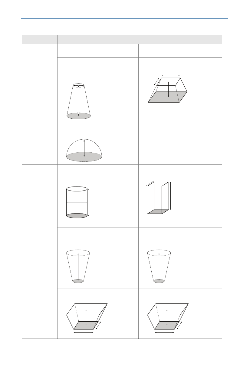
2.2 Vessel type and dimensions
Vessel d etail s
Vessel type Cylindrical Rectangular
Top sha pe
(1)
ft m
Flat
Cone
Top diameter (A): ______
Height (B): ______
Dome
Height (A): ______
Flat
Pyramid
Height (A): ______ X: ______ Y: ______
July 2017
Cylinder
Diameter (A): ______
Height (B): ______
Center shape
A
B
Flat
Cone
Height (A): ______
Bottom diameter (B): ______
Bottom shape
Pyramid
Height (A): ______ X: ______ Y: ______ Height (A): ______ X: ______ Y: ______
1. Required Field - Accurate Vessel dimensions are required to allow optimal location determination.
4
Cube
Height (A): ______ X: ______ Y: ______
Flat
Cone
Height (A): ______
Bottom diameter (B): ______
A
B
Pyramid
Page 5
July 2017
+Y
-Y
+X
-X
BA
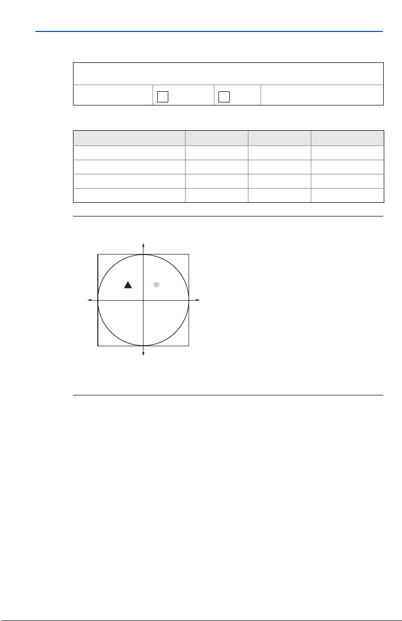
2.3 Vessel details
Internal structure like: Ladder, pipe, window, screw, door, rail, support beam or any other obstacle
which is visible to the 5708 scanner. Drawings should be available.
Internal movement: YES NO If yes, please describe:
2.4 Rosemount 5708 and filling location
X Y Offset from roof
1st Rosemount 5708 location:
2nd Rosemount 5708 location:
3rd Rosemount 5708 location:
Filling location:
Figure 1. Rosemount 5708 and Filling Port Locations
Quick Start Guide
A. Rosemount 5708 (X1, Y1)
B. Fill (X2, Y2)
When mounting more than a single Rosemount 5708 (e.g. in a system of
multiple devices), the location of all devices must be specified.
When the application has more than a single filling point, all other filling
points must be specified as well.
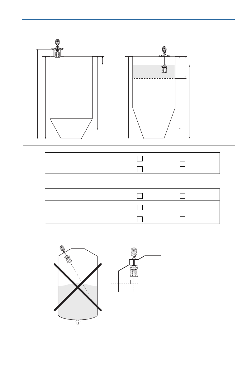
Full and empty calibration
Full and empty calibration levels are measured from the top of the vessel.
The full and empty calibration levels represent the 20 mA (100%) and 4 mA
(0%) of the volume respectably.
The Rosemount 5708 has a 20 in. (0.5 m) dead zone starting from the top
part of the antenna assembly.
5
Page 6
Quick Start Guide
Full
Calibration
Empty Calibration
Total Vessel Height
Empty Calibration
Full
Calibration
Total Vessel Height
Scanner Height
Scanner Height
D
90°
Figure 2. Full and Empty Calibration in Rectangular and Cylindrical Vessels
Full calibration: ft m
Empty calibration: ft m
2.5 Application process
July 2017
Maximum filling rate: lbs/hour tons/hour
Maximum emptying rate: lbs/hour tons/hour
Total capacity when vessel is full: lbs tons
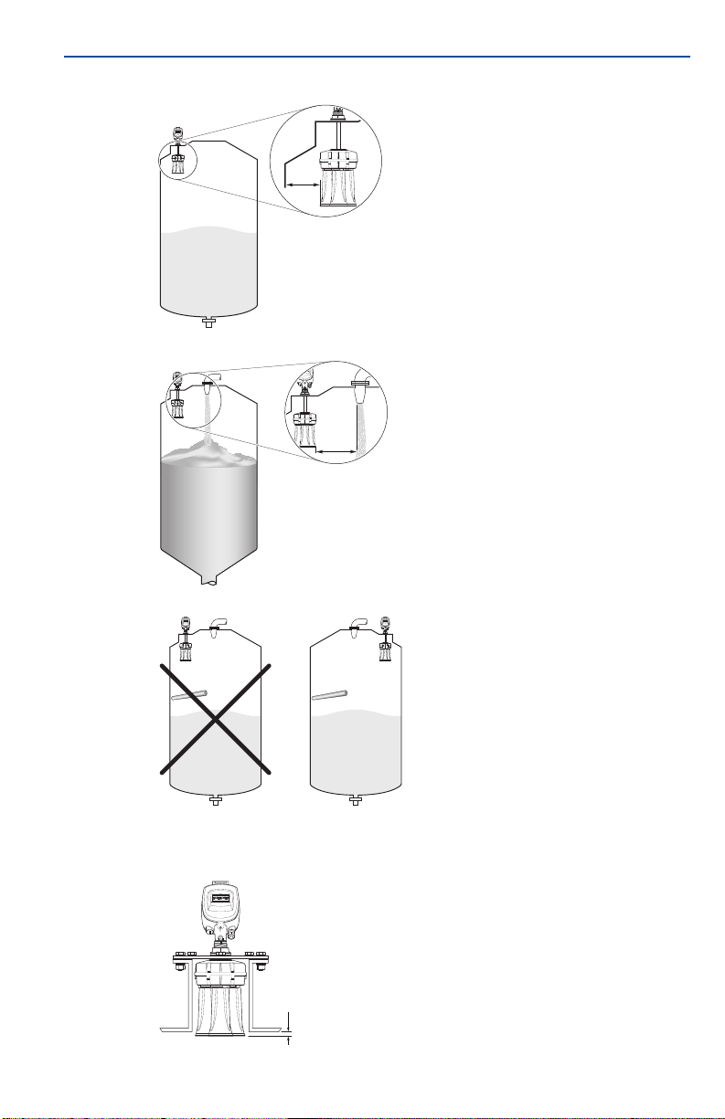
2.6 Mounting location
Mount Rosemount 5708 perpendicular to the ground.
6
Page 7
July 2017
Minimum
24 in. (600 mm)
Minimum
24 in. (600 mm)
Minimum 0.4 in. (10 mm) for standpipe mounting
Quick Start Guide
Keep necessary distance from side wall.
Keep necessary distance from filling points.
Make sure there is no obstacle below the device.
In the case of standpipe mounting, assemble and position the Rosemount
5708 at a height that leaves at least 0.4 in. (10 mm) below the standpipe for
the antenna end to protrude.
7
Page 8

Quick Start Guide
Note
Make sure the hole diameter (D) in the center is
2.05 in. (52 mm).
D
3.0 Physical mounting
Step 1: Check power and cables
1. Check the 24 Vdc with a voltmeter.
2. Check the resistance of the data communication lines.
3. Verify 60 Ω of resistance when connecting the 120 Ω resistors at both ends.
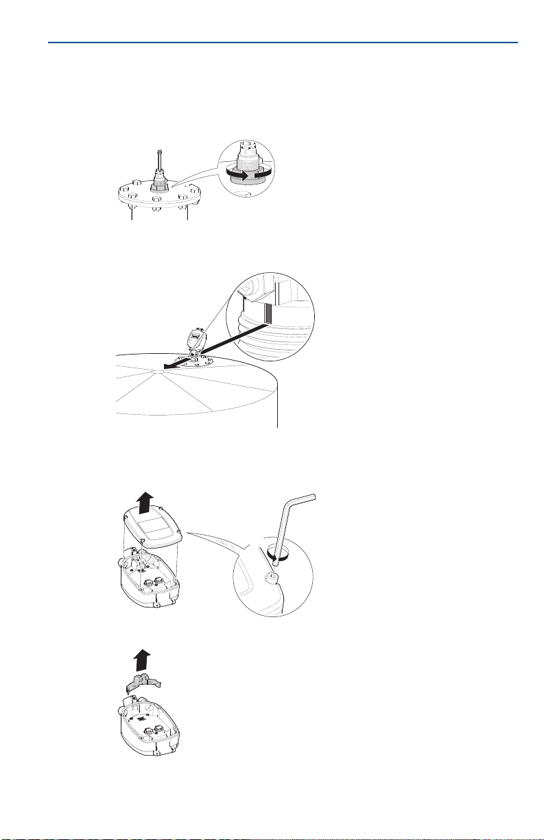
Step 2: Install the mounting plate
1. Verify the O-rings on the neck tube are in place.
2. Remove the nut from the neck tube.
July 2017
3. Place the mounting plate over the neck tube.
4. Replace the nut and tighten it over the neck tube to the mounting plate.
8
Page 9
July 2017
4x
Hex key (4 mm)
Quick Start Guide
5. Lower the antenna and mounting plate into the fitting location on the silo.
6. Bolt the mounting plate onto the flange of the silo.
Step 3: Rotate antenna toward silo center
1. Slightly loosen the nut that connects the antenna with the mounting plate.
2. Rotate the antenna. The notch on the top of the thread must be directed
toward the center of the silo.
3. Tighten nut.
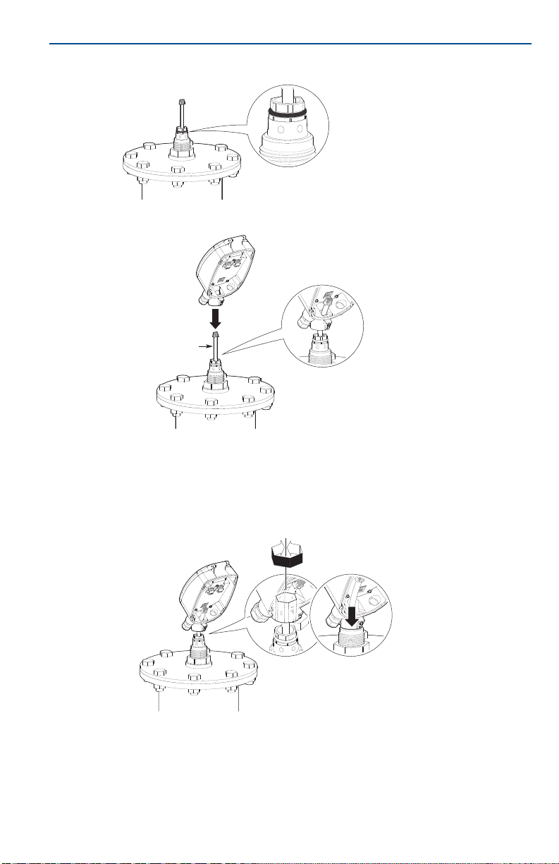
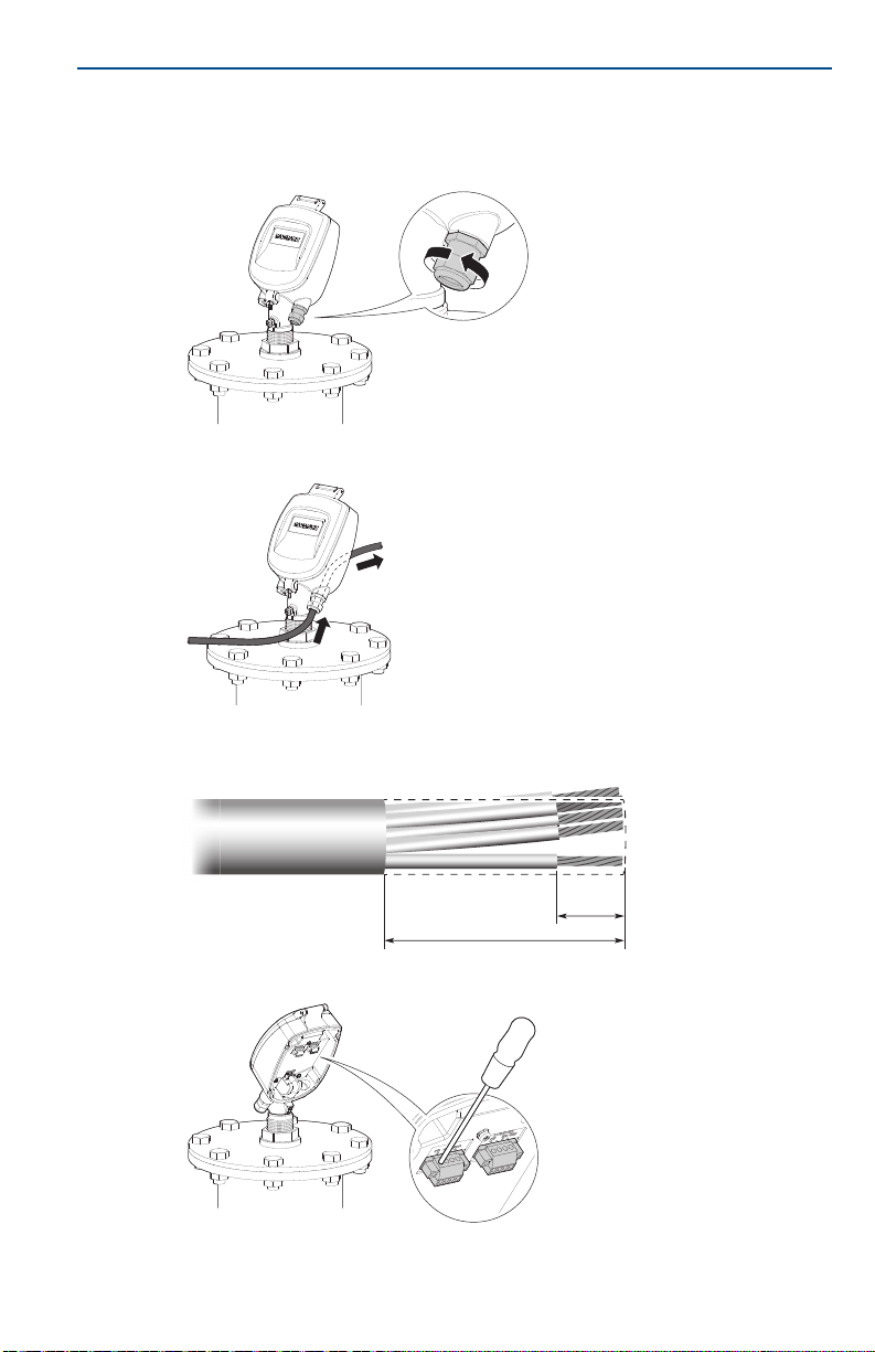
Step 4: Install head
1. Remove the rear panel.
2. Remove the cable clamp.
9
Page 10
Quick Start Guide
Antenna cable
3. Verify the presence of the O-ring on the tube neck.
4. Gently insert the antenna cable through the head.
July 2017
10
5. Insert the head onto the neck tube.
a. Rotate the head to the desired direction. The head may be installed in six
different positions. It is highly recommended to direct the head towards
the center of the silo.
b. Make sure to push the head all the way down until it fully contacts the top
of the neck tube.
Page 11
July 2017
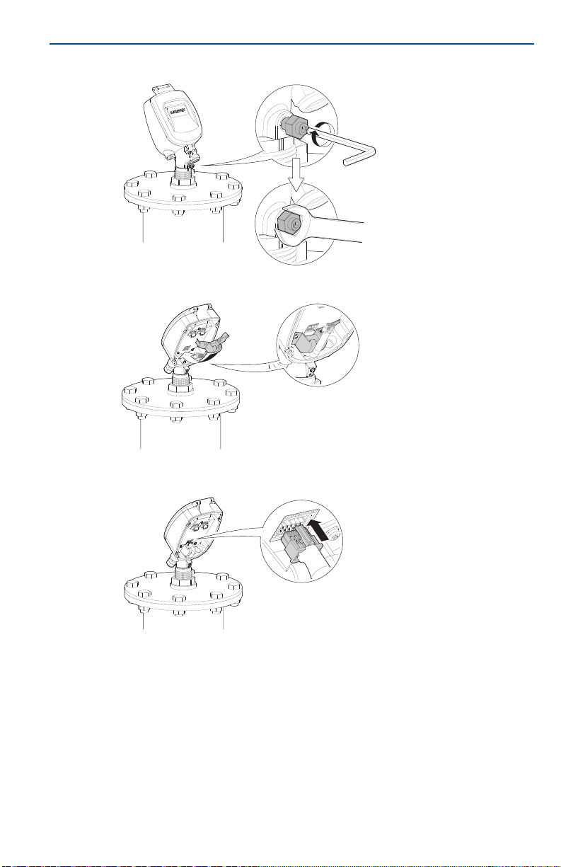
Hex key
(4 mm)
Open wrench
(13 mm)
Quick Start Guide
6. Tighten the front screw.
7. Remount the cable clamp.
8. Gently connect the antenna cable connector. Make sure the latch is clicked
and locking the connector.
11
Page 12
Quick Start Guide
4 in. (100 mm)
0.4 in.
(10
Step 5: Wire the Rosemount 5708
1. Verify the power supply is disconnected.
2. Loosen the compression nut of the cable gland entry.
3. Insert the cable into the head.
July 2017
12
4. Remove approximately 4 in. (100 mm) of the cable mantle and strip
approximately 0.4 in. (10 mm) off the edge of each conductor.
5. Loosen the terminal block screws located inside the head.
Page 13

July 2017
-
+
RS-485/Modbus RTU
communication terminals
4-20 mA
communication terminals
-
+
Feed in power supply
20-32 Vdc+-
Note
When connecting the last Rosemount 5708 in the chain, a 120 Ω resistor must be
connected as well. Check polarity of the power entity before connecting the device.
External ground screw
Note
An internal cable grounding connection is also possible using the inner connection as
shown below.
Internal ground screw
Quick Start Guide
6. Connect the cable wires according to the wiring diagram. See page 14 for
different connection methods.
7. Connect the external ground terminal.
The Rosemount 5708 must be grounded electrostatically.
For internal grounding, use the power cable ground.
For external grounding, use the earth potential equalization of the plant.
13
Page 14

Quick Start Guide
250 Ω
24DC
A
C
B
D
E
F
G
8. Tighten the compression nut over the cable gland entry opening.
9. Attach the rear panel back to position and tighten the screws.
4x
Step 6: Different connection methods
Use RS-485 or 4-20 mA connection for communication.
Figure 3. Wiring the 4-20mA to Smart Wireless THUM™ Adapter
July 2017
A. Rosemount 5708 housing ground shield E. White
B. THUM Adapter F. Bl a ck
C. Green G. Red
D. Yellow
14
Page 15

July 2017
Rosemo unt
5708 1
RS-485 (+)
120 Ω
RS-485 (-)
RS-485 (+)
120 Ω
RS-485 (-)
Rosemo unt
5708 2
Rosemo unt
5708 3
Rosemo unt
5708 n
Active
Passive
4-20 mA
PLC / Controller
Navigates back within a function menu.
Continuous 3 second press exits to the default screen.
Navigates upwards in the navigation list.
Navigates right within a function.
Navigates downwards in the navigation list.
Navigates left within a function.
Navigates to the right when within a function group.
Stores a value once configured.
Figure 4. Rosemount 5708 Connection
Figure 5. 4-20 mA Connection
Quick Start Guide
This type of connection is ac tive and not passive, hence the device is the active module and the PLC should
be the passive module.
4.0 Configuration using the LCD display
4.1 On-board configuration
The Rosemount 5708L can be completely configured via the LCD display.
For the Rosemount 5708V and 5708S, the Rosemount 3DVision software is
required.
Figure 6. User Interface
ESC
E
15
Page 16

Quick Start Guide
Rosemount
5708LNN
Initialization
Initialization
Please Wait...
m
ft
<tag name>
3.45m Avg Dist.
█████████████▒▒▒▒▒
M
July 2017
1. Connect power and open the front
cover.
A self-test will start and run for about
30 seconds the display remains blank
during this time.
2. After initialization, the version screen
appears.
According to the factory default
settings, after power initiation or
scanner restart, a screen prompts for
configuration.
In the main menu, select Basic
Settings.
3. Use the / keys to switch
between the options.
Press to select and continue with
E
the settings or to exit to the
ESC
main screen.
4. When the startup process is complete,
the following screen appears showing
the current average distance
measurement.
The top line displays the tag name. By
default, this line is empty.
Press to enter the main menu.
E
16
Page 17

July 2017
<tag name>
3.45m Avg Dist.
█████████████▒▒▒▒▒
M
E
Basic Settings
Advanced Settings
False Echo Mapping
Polling Address
Polling Address
0
0
ESC
<tag name>
3.45m Avg Dist.
█████████████▒▒▒▒▒
M
Basic Settings
Advanced Settings
False Echo Mapping
Polling Address
4.2 Setting the polling address
Setting the device address is mandatory when multiple devices are connected
over an RS-485 Multidrop (daisy chain). Set the addresses prior to use of the
Rosemount 3DVision software.
Quick Start Guide
For the Rosemount 5708V and 5708S, only polling address configuration is
done using the LCD display.
The rest of the configuration is completed with the Rosemount 3DVision
software.
1. From the main screen, press the key
to enter the main menu.
2. In the main menu, use the / keys
to scroll down to Polling Address.
Press to switch to the Polling
E
Address configuration screen.
3. Use the key to switch between the
two digits. Use the key to modify
the value.
The default polling address is 00. The
polling address ranges from 00 to 63.
E
Press to store the modified address
and to exit to the main screen.
4.3 Configuring the Rosemount 5708L
Basic Settings configuration
1. From the main screen, press the
key to enter the main menu.
2. In the main menu, use the /
keys to scroll down to Basic Settings.
Press to switch to the Basic
E
Settings screen.
E
17
Page 18

Quick Start Guide
m
ft
Set Vessel Height
2
0.000 m
Cylindrical Vessel
Rectangular Vessel
Set Vessel Diameter
1
0.000 m
Set Scanner Height
2
0.000 m
Scanner Distance
From Center
0
0.000 m
E
July 2017
3. Set the distance units, either meters
(m) or feet (ft).
4. Set Vessel Height from the vessel
bottom edge to the vessel top edge.
Use the key to switch between the
two digits. Use the key to modify
the value.
5. Select the vessel shape, either
Cylindrical or Rectangular.
Use the / keys to switch
between the options. Press to
E
continue.
a. If Cylindrical is selected, set
vessel diameter.
Use the key to switch between
the two digits. Use the key to
modify the value. Press to
E
continue.
18
b. Set Scanner Height from the
bottom edge of the vessel to the
scanner’s mounting plate (point
above the antenna).
Use the key to switch between
the two digits. Use the key to
modify the value. Press to
E
continue.
c. Set Scanner Distance from
Center.
Use the key to switch between
the two digits. Use the key to
modify the value. Press to exit
to the main screen.
Page 19

July 2017
Set Vessel Width
0
10.000 m
Set Vessel Length
0
10.000 m
Set Scanner Height
2
0.000 m
Scanner X To Center
±000.00 m
Scanner Y To Center
±000.00 m
Quick Start Guide
6. If Rectangular is selected, set vessel
width first (dimension on the x-axis).
a. Use the key to switch between
the two digits. Use the key to
modify the value. Press to
E
continue.
b. Set Vessel Length (dimension on
the y-axis).
Use the key to switch between
the two digits. Use the key to
modify the value. Press to
E
continue.
c. Set Scanner Height from the
bottom edge of the vessel to the
scanner’s mounting plate (point
above the antenna).
Use the key to switch between
the two digits. Use the key to
modify the value. Press to
E
continue.
d. Set the scanner’s distance from
the x-axis, see Figure 1 on page 5.
Use the key to switch between
the two digits. Use the key to
modify the value. Press to
E
continue.
e. Set the scanner’s distance from
the y-axis, see Figure 1 on page 5.
Use the key to switch between
the two digits. Use the key to
modify the value. Press to exit
E
to the main screen.
19
Page 20

Quick Start Guide
<tag name>
3.45m Avg Dist.
█████████████▒▒▒▒▒
Menu
E
Basic Settings
Advanced Settings
False Echo Mapping
Polling Address
Set Distance
To Full Calibration
0
0.500 m
Set Distance
To Empty Calibration
2
0.000 m
Set Adaptor Angle
0
0
Advanced Settings configuration
After configuring the Basic Settings, perform Advanced Settings configuration.
July 2017
1. From the main screen, press the
key to enter the main menu.
2. In the main menu, scroll down to
Advanced Settings, using the key.
Press to switch to the Advanced
E
Settings configuration screen.
3. Set the distance from the mounting
plate (top of the scanner’s antenna) to
the Full calibration point/100% level
point.
Use the key to switch between the
two digits. Use the key to modify
the value. Press to continue.
E
4. Set the distance from the mounting
plate (top of the scanner’s antenna) to
the Empty calibration point/0% level
point.
Use the key to switch between the
two digits. Use the key to modify
the value. Press to continue.
E
20
5. Press to keep the default setting.
E
Note: if using an angle adaptor, set the
angle value.
Use the key to switch between the
two digits. Use the key to modify
the value. Press to continue.
E
Page 21

July 2017
Slow Process
Regular Process
Fast Process
Celsius
Fahrenheit
E
Distance
Level
Volume
Analog Output
SNR
<tag name>
3.45m Avg Dist.
█████████████▒▒▒▒▒
Menu
Basic Settings
Advanced Settings
False Echo Mapping
Polling Address
Quick Start Guide
6. Set the process rate using the key.
Press to continue.
E
Make sure to always use Regular
Process.
For the Slow and Fast Process options,
contact your local customer service.
7. Set the temperature units using the
key. Press to continue.
8. Set the displayed parameter desired
for the main screen using the key.
Press to exit to the main screen.
E
False Echo Mapping
When the configuration is finished, set False Echo Mapping.
1. From the main screen, press the
E
key to enter the main menu.
2. In the main menu, scroll down to False
Echo Mapping, using the key.
Press to switch to the False Echo
E
Mapping configuration screen.
21
Page 22

Quick Start Guide
Map False Echoes
Reset Mapping
Distance To Map
False Echo
0
0.000 m
Fal se Ec ho Area
Decline Mapping
Approve Mapping
E
Decline Mapping
Approve Mapping
E
July 2017
3. Select Map False Echoes for
automatically mapping all the false
echoes up to a certain distance.
Or select Reset Mapping for deleting
the stored mapped false echoes from
the memory of the scanner.
Use the key to go down the list.
Press to continue.
E
a. If Map False Echoes is selected,
set the distance from the top of
the antenna assembly to the end
of the scanning point. Always
make sure to map false echoes
above material level. The
recommended level is 3 ft. (1 m)
above actual material level.
Use the key to switch between
the two digits. Use the key to
modify the value. Press to
E
continue.
b. Approve or decline the false echo
mapping operation.
Use the key to go down the
list. Press to continue.
22
c. If Reset Mapping is selected,
approve or decline the operation.
Use the key to go down the
list. Press to continue.
Page 23

July 2017
Quick Start Guide
5.0 Configuration using Rosemount 3DVision
5.1 Installing the Rosemount 3DVision software
The software is comprised of two components: a server and a client. For initial
configuration, it is recommended to install both the server and the client on the
same computer. However, it is possible to install the Rosemount 3DVision
Server and Client on separate computers and connect to them accordingly.
1. Insert the flash drive into the USB port.
2. Select Install Rosemount 3DVision and follow the on-screen instructions.
If the installation program does not start automatically, run Installer.exe
from the flash.
5.2 Starting Rosemount 3DVision
1. Double-click the Rosemount 3DVision desktop icon .
After a few seconds, the Rosemount 3DVision Server Connection window
appears.
2. Select Device Configuration (default) to start configuration.
23
Page 24

Quick Start Guide
3. Set the correct connection type, polling address, and serial port. Select
Connect.
After selecting the Connect button, the software automatically connects
and downloads the parameters from the Rosemount 5708.
4. After the connection has been made, Configuration Wizard appears:
a. Step 1/4: Set up general information and vessel dimensions.
b. Step 2/4: Set up device position.
c. Step 3/4: Set up filling points.
d. Step 4/4: Set up full and empty calibration. Select Finish to complete
July 2017
vessel configuration.
5.3 Performing Echo Curve Analysis
This step should only be performed if the distance given by the Rosemount is
incorrect.
When first configuring the Rosemount 5708, it is recommended to perform
Echo Curve Analysis. Using the Echo Curve Analysis it is possible to determine if
any of the advanced parameters need additional changes.
24
Page 25

July 2017
On the Device menu, select Echo Curve Analysis. Then make sure the
check-box is checked, then select the Start button.
Once the Echo Curve Analysis is complete, the echo curve window will pop up.
This function is also available via Device > Echo Curve Analyze Viewer.
5.4 Performing False Echo Mapping
With this option it is possible to perform a false echo mapping on any of the
beams to ignore false echoes inside the vessel caused by internal objects or
other interferences.
1. On the Device menu, select Device False Echo Mapping.
2. Set the From and To distances to perform false echo mapping.
3. Select the Start Scanning button.
Quick Start Guide
25
Page 26

Quick Start Guide
6.0 Post installation procedures
1. Perform hand measurement to the material.
2. Compare data with the result of distance measurement performed by the
Rosemount 5708:
a. Reference point for measurements and comparisons is the top part of the
antenna assembly.
b. Test the device while silo is idle.
c. Measure as close to the Rosemount 5708 as possible.
d. In some models, the device has minimum and maximum values for
distance. Check if the hand dip is between these measurement.
3. Coordinate filling and emptying processes.
a. Follow the Rosemount 5708 measurements during the process.
b. Check and compare distance.
c. Follow the log trends in Rosemount 3DVision.
4. Perform echo curve analysis and false echo mapping. For detailed
information, see the Rosemount 5708 Reference Manual
5. Adjust advanced parameters. For more information, see the Rosemount
5708 Reference Manual.
July 2017
.
26
Page 27

July 2017
+ -
PS OUT
Display
+ -
PS OUT
Display
++--
PS IN 4...20mA
+ -
RS-485 PS IN 4...20mA RS-485
++-- + -
++--
PS IN 4...20mA
+ -
RS-485
++--
PS IN 4...20mA
+ -
RS-485
Convert
120 Ω
resistor
PLC / DCS / Display
4-20 mA is a 2 wire,
non-loop powered,
active device connection
24 Vdc
power
supply
Rosemount 3DVision Server
120
Ω resistor
7.0 Rosemount 5708S in a system
7.1 System components
Multiple units of Rosemount 5708S
Quick Start Guide
7.2 Physical mounting
7.3 Wiring
Rosemount System Controller
1. Install the devices as written in “Physical mounting” on page 8.
2. Repeat installation steps until all are installed.
Power
A single 24 Vdc power supply is for all devices within the system.
27
Page 28

Quick Start Guide
RS-485 communication
Every Rosemount 5708 should be connected in daisy chain. For more
information, see “Rosemount 5708 Connection” on page 15.
4-20 mA connection
Since every Rosemount 5708 in the daisy chain outputs the same data, it does
not matter which device the 4-20 mA output is derived from. The 4-20 mA
output represents the volume calculated by devices in the vessel.
Grounding
For grounding information, see page 13.
7.4 On-board configuration (Rosemount 5708S)
1. Configure polling addresses only.
2. Make sure each device has a different polling address and at least one has
polling address 00.
For detailed information on polling address configuration, see “Setting the
polling address” on page 17.
7.5 Configuring using Rosemount 3DVision
For detailed information on configuring the Rosemount 5708 and Rosemount
System Controller, refer to the Rosemount 5708 Reference Manual.
7.6 Maintenance
July 2017
28
Preventive maintenance procedure
The following periodic maintenance procedure is recommended for keeping the
Rosemount 5708 in proper operating conditions and preventing unnecessary
malfunctioning which may be caused by environmental factors during time:
Clean the interior part of the antennas (see details below).
Visually check and ensure the communication and power cables are in good
condition and are not damaged.
Check and ensure proper sealing of cable entry openings.
Open the rear side of the Rosemount 5708 head and ensure absence of
wetness.
Antenna cleaning guidelines:
Disconnect power to the Rosemount 5708.
Disassemble the mounting plate and carefully pull out the entire Rosemount
5708.
Use a brush or wet cloth for the purpose of cleaning.
As necessary, water can be used for cleaning.
Avoid usage of sharp tools such as screwdrivers for cleaning. Such tools may
damage the membranes.
Preventive maintenance frequency
The frequency of the maintenance procedure is subject to the conditions and
the type of material stored in the vessel. In the case of materials such as salt,
sugar, calcium carbonate etc., treatments should be more frequent.
Page 29

July 2017
8.0 Product certifications
Rev 1.2
8.1 European Directive Information
A copy of the EC Declaration of Conformity can be found on page 35. The most recent
revision of the EC Declaration of Conformity can be found at Emerson.com/Rosemount
8.2 Ordinary Location Certification
As standard, the transmitter has been examined and tested to determine that the design
meets the basic electrical, mechanical, and fire protection requirements by a nationally
recognized test laboratory (NRTL) as accredited by the Federal Occupational Safety and
Health Administration (OSHA).
8.3 North America
I5 US and Canada Intrinsic Safety (IS)
Certificate: 3052166
Standards: FM Class 3600 - 2011, FM Class 3610 - 2010, FM Class 3810 - 2005,
ANSI/IEC 60529 - 2004, CSA Std. C22.2. No. 25- 09,
CSA Std. C22.2. No.157-92, CSA Std. C22.2 No. 1010 - 04, CAN/CSA
E61241-1-1 - 2010
Markings: IS CL I, II DIV 1, GP C, D, E, F, G when connected per Rosemount
drawing 05708-1900; T4(-40 °C <
modules with serial number 836xxxxxxx:
Supplies - Terminals J5.1 (+), J5.2 (GND) U
= 3 W, Ci = 8 nF, Li = 0
P
i
Interfaces - Terminals J5.4 (4 - 20 mA signal),
J5.3 (GND common with J5.2): U
= 1.1 W, Ci = 8 nF, Li = 0 μH
P
i
RS-485 - Terminals J6.3 (P), J6.4 (N): U
I
= 651 mA, Pi = 1.06 W, Ci = 0 nF, Li = 0 μH
i
Approval valid for HART and Modbus
= 10.5 V, Ii = 106 mA,
i
Quick Start Guide
Ta < +85 °C); IP 6XFor electronic
= 24 V, Ii = 125 mA,
i
= 6.51 V,
i
®
options.
.
Special Conditions for Safe Use (X):
1. The 3D Solids Scanner is only for use with electronics unit marked with serial number
836xxxxxx, as these units are for use with the 3D Solids ambient temperature range.
2. Part of the enclosure is constructed of plastic. To prevent the risk of electrostatic
sparking, the plastic surface should be cleaned with a damp cloth.
29
Page 30

Quick Start Guide
8.4 Europe
I1 AT EX In trins ic S afet y
Certificate: BVS14ATEXE060X
Standards: EN60079-0:2012, EN60079-11:2012
Markings: II 2 G Ex ib [ia] IIB T4 Gb (-40 °C <
Tabl e 1. Inte rface P ara meter s
Parameter 4-20 mA RS-485
Volt age U
Current I
Power P
Capacitance C
Inductance L
Capacitance C
Inductance L
L
/ R
o
o
Characteristics Trapezoid Linear
Terminals J5.3 (4-20 mA), J5.4 (GND) J6.3 (+), J6.4 (RTN)
Table 2. Supply Circuit Parameters
Parameter 4-20 mA Output
Volt age U
Current I
Power P
Capacitance C
Inductance Li/L
Lo / Ro ratio
Characteristics
Ter mi na l s
II 1/2 D Ex ib [ia] IIIC T110 °C Da/Db (-40 °C <
/ U
i
/ I
i
o
/ P
i
o
/ U
i
i
/ P
i
o
10.5 V 6.51 V
o
106 mA 2 x 651 mA
1.1 W 2 x 1.06 W
8 nF 0 nF
i
~0 mH 0 mH
i
16 μF 2 x 285 μF
o
80 μH 83.9 μH
o
17.77 μH/Ω 67.12 μH/Ω
24 V N/A
o
Same values as the
interconnected IS power supply
3 W N/A
/ C
8 nF
i
o
~0 mH
o
N/A
N/A
J5.1 (+), J5.2 (GND) N/A
Ta < +85 °C)
Ta < +85 °C)
N/A
Same values of the
interconnected IS power supply
reduced by C
Same values of the
interconnected IS power supply
reduced by L
Same values of the
interconnected IS power supply
reduced by L
Same values as the
interconnected IS power supply
i
i
i
July 2017
30
Special Condition for Safe Use (X):
1. Dust application:
The installation of the 3D Solids Scanner or of the Antenna Unit of models providing
head separation in the wall to areas requiring EPL Da (apparatus category 1D)
equipment shall provide a degree of protection IP6X according to EN60529 and shall
be carried out in such a way, that all metallic parts are integrated in the local
equipotential bonding.
Manufacturer’s technical information related to use of the 3D Solids Scanner in
contact with aggressive/corrosive media and to avoid any risk of mechanical impact
shall be observed.
Page 31

July 2017
8.5 International
I7 IECEx Intrinsic Safety
Certificate: IECEx BVS 15.0042X
Standards: IEC 60079-0: 2011, IEC 60079-11: 2011
Markings: Ex ib [ia] IIB T4 Gb (-40 °C <
Ex ib [ia] IIIC T110°C Da/Db (-40 °C <
Table 3. Interface Parameters
Parameter 4-20 mA RS-485
Volta ge U
Current I
Power P
Capacitance C
Inductance L
Capacitance C
Inductance L
L
Characteristics
Ter mi na l s
Table 4. Supply Circuit Parameters
Parameter Input Output
Volta ge U
Current I
Power P
Capacitance C
Inductance Li/L
Lo / Ro ratio
Characteristics
Ter mi na l s
/ U
i
/ I
i
o
/ P
i
o
/ R
o
o
10.5 V 6.51 V
o
106 mA 2 x 651 mA
1.1 W 2 x 1.06 W
8 nF 0 nF
i
~0 mH 0 mH
i
16 μF 2 x 285 μF
o
80 μH83.9 μH
o
17.77 μH/Ω 67.12 μH/Ω
Tra pe zo id Li n ea r
J5.3 (4-20 mA), J5.4 (GND) J6.3 (+), J6.4 (RTN)
/ U
i
i
/ P
i
o
26.6 V N/A
o
Same values as the
interconnected IS power supply
3 W N/A
/ C
8 nF
i
o
~0 mH
o
N/A
N/A
J5.1 (+), J5.2 (GND) N/A
Ta < +85 °C)
Ta < +85 °C)
Quick Start Guide
N/A
Same values of the interconnected
IS power supply reduced by C
Same values of the interconnected
IS power supply reduced by L
Same values of the interconnected
IS power supply reduced by L
Same values as the interconnected
IS power supp ly
i
i
i
Special Condition for Safe Use (X):
1. Dust application:
The installation of the 3D-Solids Scanner or of the Antenna Unit of models providing
head separation in the wall to areas requiring EPL Da equipment shall provide a degree
of protection IP6X according to IEC 60529 and shall be carried out in such a way, that
all metallic parts are integrated in the local equipotential bonding. Manufacturer's
technical information related to use of the 3D Solids Scanner in contact with
aggressive/corrosive media and to avoid any risk of mechanical impact shall be
observed.
31
Page 32

Quick Start Guide
8.6 China
I3 China Intrinsic Safety
Certificate: GB3836.1-2010, GB3836.4-2010, IEC61241-0 - 2004,
Markings: Ex ib/ia IIB Gb T4
Special Condition for Safe Use (X):
1. The installation of the product shall provide a degree of protection IP6X according to
GB4208-2008, and in such a way that all metallic parts are integrated in the local
equipotential bonding.
8.7 Brazil
I2 INMETRO Intrinsic Safety
Certificate: UL-BR 15.0072X
Standards: ABNT NBR IEC 60079-0:2008 + Errata 1:2011,
Markings: Ex ib [ia] IIB T4 Gb (- 40 °C <
Special Condition for Safe Use (X):
1. Dust application:
The installation of the 3D Solids Scanner or of the Antenna Unit of models providing
head separation in the wall to areas requiring EPL Da (Zone 20) equipment shall
provide a degree of protection IP6X according to ABNT NBR IEC 60529 and shall be
carried out in such a way, that all metallic parts are integrated in the local equipotential
bonding.
Manufacturer's technical information related to use of the 3D Solids Scanner in contact
with aggressive/corrosive media and to avoid any risk of mechanical impact shall be
observed.
GB12476.4-2010
Ex ibD/iaD 21/20 T110 °C
ABNT NBR IEC 60079-11:2009
Ta < + 85 °C)
Ex ib [ia] IIIC T110 °C Da/Db (- 40 °C <
July 2017
Ta < + 85 °C)
32
Page 33

July 2017
8.8 EAC
IM Intrinsic Safety by TR CU 012/2011
Markings: 1Ex ib [ia] IIB T4 Gb X (-40 <
Ex ib [ia] IIIC T110 °C Da/Db X (-40 <
Table 5. Input parameters
Quick Start Guide
Tamb < 85 °C)
Tamb < 85 °C)
Parameters
Level of
protection
Vol tag e Ui = 24 V Uo = 24 V Ui = Uo = 10,5 V Ui = Uo = 6,51 V
Current I
Power Pi = 3 W Po = 3 W
Capacitance Ci 8 nF 8 nF мала
Capacitance CoN/A
Inductance Li Negligible Negligible Negligible
Inductance Lo N/A
Lo/Ro N/A
Characteristics N/A
Ter mi na l s J5.1 (+), J5.2 (GND) J6.1 (+), J6.2 (GND) J5.3 (4–20 mA), J5.4 (GND) J6.3 (+), J6.4 (RTN)
1. J5.1, J5.2 directly connected to J6.1, J6.2.
2. Same values as of the interconnected IS power supply.
3. Same values as of the interconnected IS power supply reduced by Ci, Li.
Input Output
Ex ib IIB /
Ex ib IIIC
(2)
i
Supply circuit Interface
Ex ib IIB /
Ex ib IIIC
(2)
I
o
(1)
(2)
(3)
(3)
(3)
(2)
4-20 mA RS 485
Ex ia IIB /
Ex ia IIIC
Ii = Io = 106 mA Ii = Io = 2 × 651 mA
Pi = Po = 1,1 W Pi = Po = 2 ×1,06 W
16 μF 2 × 285 μF
80 μH 83.9 μH
17.77 μH /Ohm 67.12 μH /Ohm
Tra pe zo id Linear
Ex ia IIB /
Ex ia IIIC
Special Conditions for Safe Use (X):
1. Level meter should be installed and operated in such a way that no danger of ignition
due to electrostatic discharge.
2. The instructions specified in the manual, eliminates the risk of corrosion and / or
mechanical action.
3. When the level meter, which provides separation of the head in areas requiring
protection level equipment Da, the degree necessary to provide protection for at least
IP6X in accordance with GOST 14254-96 and assembly should be performed so that all
metal parts have the same potential.
8.9 India
IW PESO Intrinsic Safety
Certificate: P351811/1
Standards: EN 60079-0: 2012, EN 60079-11: 2012
Markings: Ex ib {ia} IIB t4 Gb
33
Page 34

Quick Start Guide
8.10 Korea
IP KTL Intrinsic Safety
Certificate: 15-KA4BO-0298X - ex
Standards: IEC 60079-0: 2011, IEC 60079-11: 2011
Markings: Ex ib [ia] IIB T4 Gb, Ex ib [ia] IIIC T110C Da/Db
July 2017
For detailed information on configuring the Rosemount 5708 and Rosemount System
Controller, refer to the Rosemount 5708 Reference
Manual.
34
Page 35

July 2017
Figure 7. Rosemount 5708 Declaration of Conformity
Quick Start Guide
35
Page 36

Quick Start Guide
July 2017
36
Page 37

July 2017
9.0 Installation drawing
Figure 8. Wiring Drawing for Intrinsically Safe 3D Solids Scanner
Quick Start Guide
37
Page 38

Global Headquarters
Emerson Automation Solutions
6021 Innovation Blvd.
Shakopee, MN 55379, USA
+1 800 999 9307 or +1 952 906 8888
+1 952 949 7001
RFQ.RMD-RCC@Emerson.com
North America Regional Office
Emerson Automation Solutions
8200 Market Blvd.
Chanhassen, MN 55317, USA
+1 800 999 9307 or +1 952 906 8888
+1 952 949 7001
RMT-NA.RCCRFQ@Emerson.com
Latin America Regional Office
Emerson Automation Solutions
1300 Concord Terrace, Suite 400
Sunrise, FL 33323, USA
+1 954 846 5030
+1 954 846 5121
RFQ.RMD-RCC@Emerson.com
Europe Regional Office
Emerson Automation Solutions
Neuhofstrasse 19a P.O. Box 1046
CH 6340 Baar
Switzerland
+41 (0) 41 768 6111
+41 (0) 41 768 6300
RFQ.RMD-RCC@Emerson.com
Asia Pacific Regional Office
Emerson Automation Solutions
1 Pandan Crescent
Singapore 128461
+65 6777 8211
+65 6777 0947
Enquiries@AP.Emerson.com
Middle East and Africa Regional Office
Emerson Automation Solutions
Emerson FZE P.O. Box 17033
Jebel Ali Free Zone - South 2
Dubai, United Arab Emi rates
+971 4 8118100
+971 4 8865465
RFQ.RMTMEA@Emerson.com
*00825-0100-4570*
Quick Start Guide
00825-0100-4570, Rev CB
Linkedin.com/company/Emerson-Automation-Solutions
Twitter.com/Rosemount_News
Facebook.com/Rosemount
Youtube.com/us er/RosemountMeasu rement
Google.com/+RosemountMeasurement
Standard Terms and Conditions of Sale can be found on the Term s
and Conditions of Sale page.
The Emerson logo is a trademark and service mark of Emerson
Electric Co.
Rosemount and Rosemount logotype are trademarks of Emerson.
Modbus is a registered trademark of Gould Inc.
HART is a registered trademark of the FieldComm Group.
All other marks are the property of their respective owners.
© 2017 Emerson. All rights reserved.
July 2017
 Loading...