

Page 1
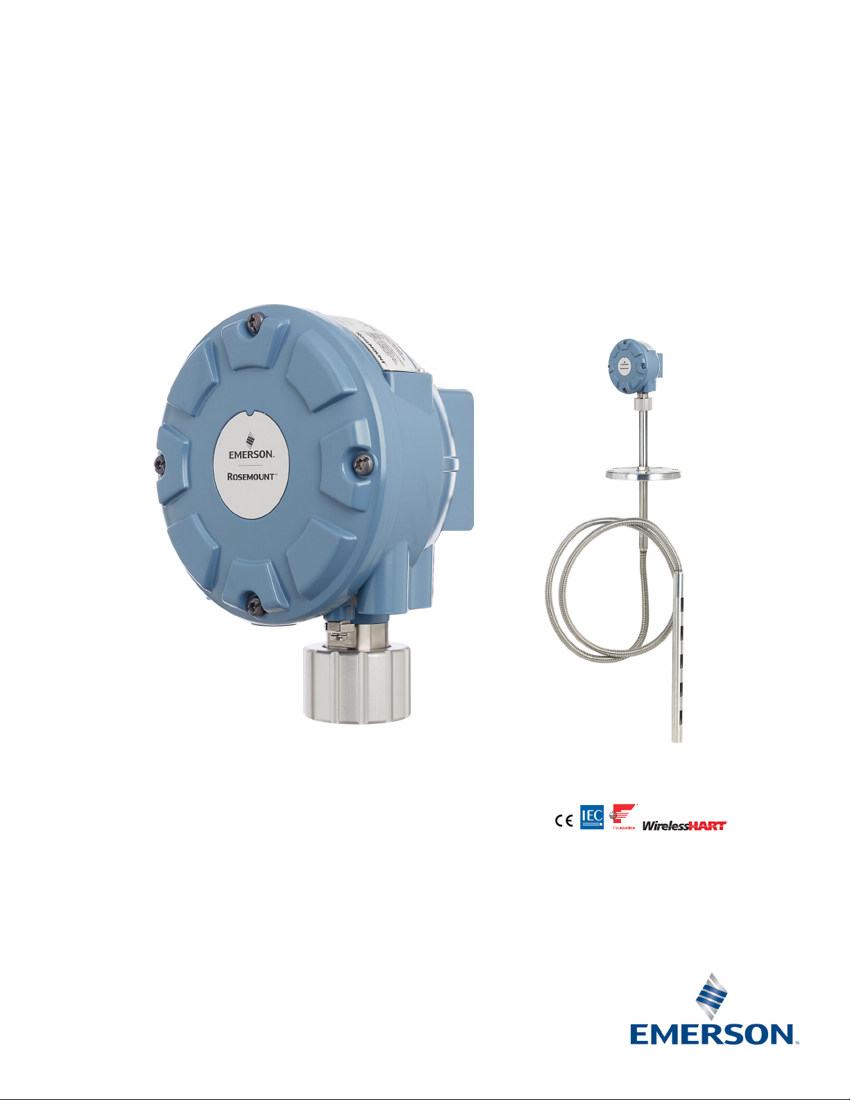
Rosemount™ 2240S Multi-Input
Temperature Transmitter
Reference Manual
00809-0100-2240, Rev EA
May 2020
Page 2

Page 3

Reference Manual
00809-0100-2240, Rev EA
Contents
1Section 1: Introduction
Contents
May 2020
1.1 Safety messages. . . . . . . . . . . . . . . . . . . . . . . . . . . . . . . . . . . . . . . . . . . . . . . . . . . . . . . . . . . . . . . . . . . 1
1.2 Manual overview . . . . . . . . . . . . . . . . . . . . . . . . . . . . . . . . . . . . . . . . . . . . . . . . . . . . . . . . . . . . . . . . . . 2
1.3 Technical documentation . . . . . . . . . . . . . . . . . . . . . . . . . . . . . . . . . . . . . . . . . . . . . . . . . . . . . . . . . . 3
1.3.1 Reference manuals. . . . . . . . . . . . . . . . . . . . . . . . . . . . . . . . . . . . . . . . . . . . . . . . . . . . . . . . . . . 3
1.3.2 Product data sheets . . . . . . . . . . . . . . . . . . . . . . . . . . . . . . . . . . . . . . . . . . . . . . . . . . . . . . . . . . 3
1.3.3 Drawings . . . . . . . . . . . . . . . . . . . . . . . . . . . . . . . . . . . . . . . . . . . . . . . . . . . . . . . . . . . . . . . . . . . 4
1.4 Service support. . . . . . . . . . . . . . . . . . . . . . . . . . . . . . . . . . . . . . . . . . . . . . . . . . . . . . . . . . . . . . . . . . . . 5
1.5 Product recycling/disposal. . . . . . . . . . . . . . . . . . . . . . . . . . . . . . . . . . . . . . . . . . . . . . . . . . . . . . . . . . 5
1.6 Packing material . . . . . . . . . . . . . . . . . . . . . . . . . . . . . . . . . . . . . . . . . . . . . . . . . . . . . . . . . . . . . . . . . . 6
1.6.1 Reuse and recycling . . . . . . . . . . . . . . . . . . . . . . . . . . . . . . . . . . . . . . . . . . . . . . . . . . . . . . . . . . 6
1.6.2 Energy recovery . . . . . . . . . . . . . . . . . . . . . . . . . . . . . . . . . . . . . . . . . . . . . . . . . . . . . . . . . . . . . 6
2Section 2: Overview
2.1 Introduction . . . . . . . . . . . . . . . . . . . . . . . . . . . . . . . . . . . . . . . . . . . . . . . . . . . . . . . . . . . . . . . . . . . . . . 7
2.2 Components. . . . . . . . . . . . . . . . . . . . . . . . . . . . . . . . . . . . . . . . . . . . . . . . . . . . . . . . . . . . . . . . . . . . . . 8
2.3 System overview . . . . . . . . . . . . . . . . . . . . . . . . . . . . . . . . . . . . . . . . . . . . . . . . . . . . . . . . . . . . . . . . . . 9
2.4 Getting started. . . . . . . . . . . . . . . . . . . . . . . . . . . . . . . . . . . . . . . . . . . . . . . . . . . . . . . . . . . . . . . . . . . 17
2.5 Installation procedure. . . . . . . . . . . . . . . . . . . . . . . . . . . . . . . . . . . . . . . . . . . . . . . . . . . . . . . . . . . . . 18
3Section 3: Sensor Installation
3.1 Safety messages. . . . . . . . . . . . . . . . . . . . . . . . . . . . . . . . . . . . . . . . . . . . . . . . . . . . . . . . . . . . . . . . . . 19
3.2 Installation considerations. . . . . . . . . . . . . . . . . . . . . . . . . . . . . . . . . . . . . . . . . . . . . . . . . . . . . . . . . 20
3.3 Multiple Spot Temperature sensor. . . . . . . . . . . . . . . . . . . . . . . . . . . . . . . . . . . . . . . . . . . . . . . . . . 21
3.3.1 Installation on fixed roof tanks. . . . . . . . . . . . . . . . . . . . . . . . . . . . . . . . . . . . . . . . . . . . . . . . 21
3.3.2 Installation on floating roof tanks . . . . . . . . . . . . . . . . . . . . . . . . . . . . . . . . . . . . . . . . . . . . . 22
3.3.3 Custody transfer applications . . . . . . . . . . . . . . . . . . . . . . . . . . . . . . . . . . . . . . . . . . . . . . . . 23
3.4 Water Level Sensor . . . . . . . . . . . . . . . . . . . . . . . . . . . . . . . . . . . . . . . . . . . . . . . . . . . . . . . . . . . . . . . 24
3.5 Installing a temperature sensor tube . . . . . . . . . . . . . . . . . . . . . . . . . . . . . . . . . . . . . . . . . . . . . . . . 25
3.6 Rosemount 614 Cryogenic Spot Temperature Sensor . . . . . . . . . . . . . . . . . . . . . . . . . . . . . . . . . 26
3.6.1 Leakage detection on LNG full containment tank . . . . . . . . . . . . . . . . . . . . . . . . . . . . . . . 26
Contents
3.6.2 Skin temperature and cool-down monitoring on LNG tank . . . . . . . . . . . . . . . . . . . . . . . 28
i
Page 4

Contents
May 2020
4Section 4: Rosemount™ 2240S Installation
4.1 Safety messages. . . . . . . . . . . . . . . . . . . . . . . . . . . . . . . . . . . . . . . . . . . . . . . . . . . . . . . . . . . . . . . . . . 29
4.2 Installation considerations. . . . . . . . . . . . . . . . . . . . . . . . . . . . . . . . . . . . . . . . . . . . . . . . . . . . . . . . . 30
4.3 Mechanical installation . . . . . . . . . . . . . . . . . . . . . . . . . . . . . . . . . . . . . . . . . . . . . . . . . . . . . . . . . . . . 31
4.3.1 Mounting on top of a temperature sensor/WLS . . . . . . . . . . . . . . . . . . . . . . . . . . . . . . . . . 31
4.3.2 Mounting on a pipe . . . . . . . . . . . . . . . . . . . . . . . . . . . . . . . . . . . . . . . . . . . . . . . . . . . . . . . . . 32
4.3.3 Wall mounting . . . . . . . . . . . . . . . . . . . . . . . . . . . . . . . . . . . . . . . . . . . . . . . . . . . . . . . . . . . . . 33
4.3.4 Mounting the connection cone and Rosemount 614 sensor . . . . . . . . . . . . . . . . . . . . . . 34
4.4 Electrical installation . . . . . . . . . . . . . . . . . . . . . . . . . . . . . . . . . . . . . . . . . . . . . . . . . . . . . . . . . . . . . . 37
4.4.1 Cable/conduit entries . . . . . . . . . . . . . . . . . . . . . . . . . . . . . . . . . . . . . . . . . . . . . . . . . . . . . . . 37
4.4.2 Power requirements . . . . . . . . . . . . . . . . . . . . . . . . . . . . . . . . . . . . . . . . . . . . . . . . . . . . . . . . 37
4.4.3 Grounding . . . . . . . . . . . . . . . . . . . . . . . . . . . . . . . . . . . . . . . . . . . . . . . . . . . . . . . . . . . . . . . . . 38
4.4.4 Cable selection . . . . . . . . . . . . . . . . . . . . . . . . . . . . . . . . . . . . . . . . . . . . . . . . . . . . . . . . . . . . . 39
4.4.5 Hazardous areas . . . . . . . . . . . . . . . . . . . . . . . . . . . . . . . . . . . . . . . . . . . . . . . . . . . . . . . . . . . . 40
4.4.6 The Tankbus . . . . . . . . . . . . . . . . . . . . . . . . . . . . . . . . . . . . . . . . . . . . . . . . . . . . . . . . . . . . . . . 41
4.4.7 Typical installations . . . . . . . . . . . . . . . . . . . . . . . . . . . . . . . . . . . . . . . . . . . . . . . . . . . . . . . . . 42
4.4.8 Rosemount
4.4.9 Tankbus wiring . . . . . . . . . . . . . . . . . . . . . . . . . . . . . . . . . . . . . . . . . . . . . . . . . . . . . . . . . . . . . 44
4.4.10Daisy-chain connection. . . . . . . . . . . . . . . . . . . . . . . . . . . . . . . . . . . . . . . . . . . . . . . . . . . . . . 46
™
2240S in FOUNDATION Fieldbus system . . . . . . . . . . . . . . . . . . . . . . . . . . . . . 43
Reference Manual
00809-0100-2240, Rev EA
4.4.11Temperature element and Water Level Sensor wiring . . . . . . . . . . . . . . . . . . . . . . . . . . . 47
5Section 5: Configuration/Operation
5.1 Safety messages. . . . . . . . . . . . . . . . . . . . . . . . . . . . . . . . . . . . . . . . . . . . . . . . . . . . . . . . . . . . . . . . . . 51
5.2 Introduction . . . . . . . . . . . . . . . . . . . . . . . . . . . . . . . . . . . . . . . . . . . . . . . . . . . . . . . . . . . . . . . . . . . . . 52
5.2.1 Configuration procedure . . . . . . . . . . . . . . . . . . . . . . . . . . . . . . . . . . . . . . . . . . . . . . . . . . . . 52
5.2.2 Parameters . . . . . . . . . . . . . . . . . . . . . . . . . . . . . . . . . . . . . . . . . . . . . . . . . . . . . . . . . . . . . . . . 52
5.2.3 Configuration tools . . . . . . . . . . . . . . . . . . . . . . . . . . . . . . . . . . . . . . . . . . . . . . . . . . . . . . . . . 53
5.3 Basic configuration . . . . . . . . . . . . . . . . . . . . . . . . . . . . . . . . . . . . . . . . . . . . . . . . . . . . . . . . . . . . . . . 54
5.3.1 Temperature elements . . . . . . . . . . . . . . . . . . . . . . . . . . . . . . . . . . . . . . . . . . . . . . . . . . . . . . 54
5.3.2 Water Level Sensor calibration. . . . . . . . . . . . . . . . . . . . . . . . . . . . . . . . . . . . . . . . . . . . . . . . 57
5.3.3 Water Level Sensor measuring range . . . . . . . . . . . . . . . . . . . . . . . . . . . . . . . . . . . . . . . . . . 59
5.4 LED signals. . . . . . . . . . . . . . . . . . . . . . . . . . . . . . . . . . . . . . . . . . . . . . . . . . . . . . . . . . . . . . . . . . . . . . . 64
5.4.1 Status LED . . . . . . . . . . . . . . . . . . . . . . . . . . . . . . . . . . . . . . . . . . . . . . . . . . . . . . . . . . . . . . . . . 64
5.4.2 Communication LEDs . . . . . . . . . . . . . . . . . . . . . . . . . . . . . . . . . . . . . . . . . . . . . . . . . . . . . . . 65
5.5 Switches and reset buttons . . . . . . . . . . . . . . . . . . . . . . . . . . . . . . . . . . . . . . . . . . . . . . . . . . . . . . . . 66
5.5.1 DIP Switches . . . . . . . . . . . . . . . . . . . . . . . . . . . . . . . . . . . . . . . . . . . . . . . . . . . . . . . . . . . . . . . 66
5.5.2 Reset button . . . . . . . . . . . . . . . . . . . . . . . . . . . . . . . . . . . . . . . . . . . . . . . . . . . . . . . . . . . . . . . 68
ii
Contents
Page 5

Reference Manual
00809-0100-2240, Rev EA
Contents
May 2020
5.6 Configuration using TankMaster WinSetup . . . . . . . . . . . . . . . . . . . . . . . . . . . . . . . . . . . . . . . . . . 69
5.6.1 Advanced configuration . . . . . . . . . . . . . . . . . . . . . . . . . . . . . . . . . . . . . . . . . . . . . . . . . . . . . 69
5.7 F
OUNDATION
5.7.1 Block operation. . . . . . . . . . . . . . . . . . . . . . . . . . . . . . . . . . . . . . . . . . . . . . . . . . . . . . . . . . . . . 70
5.8 Device capabilities . . . . . . . . . . . . . . . . . . . . . . . . . . . . . . . . . . . . . . . . . . . . . . . . . . . . . . . . . . . . . . . . 73
5.8.1 Link active scheduler . . . . . . . . . . . . . . . . . . . . . . . . . . . . . . . . . . . . . . . . . . . . . . . . . . . . . . . . 73
5.8.2 Device addressing . . . . . . . . . . . . . . . . . . . . . . . . . . . . . . . . . . . . . . . . . . . . . . . . . . . . . . . . . . 73
5.8.3 Capabilities . . . . . . . . . . . . . . . . . . . . . . . . . . . . . . . . . . . . . . . . . . . . . . . . . . . . . . . . . . . . . . . . 74
5.9 General block information . . . . . . . . . . . . . . . . . . . . . . . . . . . . . . . . . . . . . . . . . . . . . . . . . . . . . . . . . 75
5.9.1 Modes . . . . . . . . . . . . . . . . . . . . . . . . . . . . . . . . . . . . . . . . . . . . . . . . . . . . . . . . . . . . . . . . . . . . . 75
5.9.2 Block instantiation . . . . . . . . . . . . . . . . . . . . . . . . . . . . . . . . . . . . . . . . . . . . . . . . . . . . . . . . . . 76
5.9.3 Factory configuration . . . . . . . . . . . . . . . . . . . . . . . . . . . . . . . . . . . . . . . . . . . . . . . . . . . . . . . 76
5.10Analog Input block . . . . . . . . . . . . . . . . . . . . . . . . . . . . . . . . . . . . . . . . . . . . . . . . . . . . . . . . . . . . . . . 77
5.10.1Configure the AI block. . . . . . . . . . . . . . . . . . . . . . . . . . . . . . . . . . . . . . . . . . . . . . . . . . . . . . . 77
™
fieldbus overview. . . . . . . . . . . . . . . . . . . . . . . . . . . . . . . . . . . . . . . . . . . . . . . . . . . . . 70
5.10.2Factory supplied AI blocks . . . . . . . . . . . . . . . . . . . . . . . . . . . . . . . . . . . . . . . . . . . . . . . . . . . 79
5.10.3Modes. . . . . . . . . . . . . . . . . . . . . . . . . . . . . . . . . . . . . . . . . . . . . . . . . . . . . . . . . . . . . . . . . . . . . 79
5.10.4Simulation . . . . . . . . . . . . . . . . . . . . . . . . . . . . . . . . . . . . . . . . . . . . . . . . . . . . . . . . . . . . . . . . . 80
5.10.5Filtering . . . . . . . . . . . . . . . . . . . . . . . . . . . . . . . . . . . . . . . . . . . . . . . . . . . . . . . . . . . . . . . . . . . 80
5.10.6Signal Conversion. . . . . . . . . . . . . . . . . . . . . . . . . . . . . . . . . . . . . . . . . . . . . . . . . . . . . . . . . . . 81
5.10.7Process alarm . . . . . . . . . . . . . . . . . . . . . . . . . . . . . . . . . . . . . . . . . . . . . . . . . . . . . . . . . . . . . . 82
5.10.8Alarm priority . . . . . . . . . . . . . . . . . . . . . . . . . . . . . . . . . . . . . . . . . . . . . . . . . . . . . . . . . . . . . . 82
5.11Analog Output block . . . . . . . . . . . . . . . . . . . . . . . . . . . . . . . . . . . . . . . . . . . . . . . . . . . . . . . . . . . . . 83
5.11.1CHANNEL. . . . . . . . . . . . . . . . . . . . . . . . . . . . . . . . . . . . . . . . . . . . . . . . . . . . . . . . . . . . . . . . . . 83
5.11.2XD_SCALE . . . . . . . . . . . . . . . . . . . . . . . . . . . . . . . . . . . . . . . . . . . . . . . . . . . . . . . . . . . . . . . . . 83
5.11.3Application example . . . . . . . . . . . . . . . . . . . . . . . . . . . . . . . . . . . . . . . . . . . . . . . . . . . . . . . . 84
5.12Multiple Analog Input blocks . . . . . . . . . . . . . . . . . . . . . . . . . . . . . . . . . . . . . . . . . . . . . . . . . . . . . . 85
5.12.1Configure the MAI blocks . . . . . . . . . . . . . . . . . . . . . . . . . . . . . . . . . . . . . . . . . . . . . . . . . . . . 85
5.12.2Factory Supplied MAI blocks . . . . . . . . . . . . . . . . . . . . . . . . . . . . . . . . . . . . . . . . . . . . . . . . . 85
5.13Resource block. . . . . . . . . . . . . . . . . . . . . . . . . . . . . . . . . . . . . . . . . . . . . . . . . . . . . . . . . . . . . . . . . . . 86
5.13.1FEATURES and FEATURES_SEL . . . . . . . . . . . . . . . . . . . . . . . . . . . . . . . . . . . . . . . . . . . . . . . . 86
5.13.2MAX_NOTIFY . . . . . . . . . . . . . . . . . . . . . . . . . . . . . . . . . . . . . . . . . . . . . . . . . . . . . . . . . . . . . . 87
5.13.3Field diagnostic alerts . . . . . . . . . . . . . . . . . . . . . . . . . . . . . . . . . . . . . . . . . . . . . . . . . . . . . . . 88
5.13.4Recommended actions for alerts . . . . . . . . . . . . . . . . . . . . . . . . . . . . . . . . . . . . . . . . . . . . . 91
5.13.5Alarm priority . . . . . . . . . . . . . . . . . . . . . . . . . . . . . . . . . . . . . . . . . . . . . . . . . . . . . . . . . . . . . . 92
Contents
5.14Configuration using a field communicator. . . . . . . . . . . . . . . . . . . . . . . . . . . . . . . . . . . . . . . . . . . 93
iii
Page 6

Contents
May 2020
Reference Manual
00809-0100-2240, Rev EA
5.15Configuration using AMS Device Manager. . . . . . . . . . . . . . . . . . . . . . . . . . . . . . . . . . . . . . . . . . . 94
5.15.1Starting the Guided Setup . . . . . . . . . . . . . . . . . . . . . . . . . . . . . . . . . . . . . . . . . . . . . . . . . . . 94
5.15.2Temperature sensor setup . . . . . . . . . . . . . . . . . . . . . . . . . . . . . . . . . . . . . . . . . . . . . . . . . . . 97
5.15.3Water level sensor setup. . . . . . . . . . . . . . . . . . . . . . . . . . . . . . . . . . . . . . . . . . . . . . . . . . . . 101
5.15.4Manual setup . . . . . . . . . . . . . . . . . . . . . . . . . . . . . . . . . . . . . . . . . . . . . . . . . . . . . . . . . . . . . 103
5.16Alert setup . . . . . . . . . . . . . . . . . . . . . . . . . . . . . . . . . . . . . . . . . . . . . . . . . . . . . . . . . . . . . . . . . . . . . 106
5.16.1Alert default settings. . . . . . . . . . . . . . . . . . . . . . . . . . . . . . . . . . . . . . . . . . . . . . . . . . . . . . . 108
6Section 6: Service and Troubleshooting
6.1 Safety messages. . . . . . . . . . . . . . . . . . . . . . . . . . . . . . . . . . . . . . . . . . . . . . . . . . . . . . . . . . . . . . . . . 111
6.2 Service . . . . . . . . . . . . . . . . . . . . . . . . . . . . . . . . . . . . . . . . . . . . . . . . . . . . . . . . . . . . . . . . . . . . . . . . . 112
6.2.1 Viewing input and holding registers . . . . . . . . . . . . . . . . . . . . . . . . . . . . . . . . . . . . . . . . . . 112
6.2.2 Editing holding registers . . . . . . . . . . . . . . . . . . . . . . . . . . . . . . . . . . . . . . . . . . . . . . . . . . . . 113
6.2.3 Diagnostics . . . . . . . . . . . . . . . . . . . . . . . . . . . . . . . . . . . . . . . . . . . . . . . . . . . . . . . . . . . . . . . 114
6.2.4 Ground fault detection . . . . . . . . . . . . . . . . . . . . . . . . . . . . . . . . . . . . . . . . . . . . . . . . . . . . . 115
6.2.5 Reset and WLS calibration. . . . . . . . . . . . . . . . . . . . . . . . . . . . . . . . . . . . . . . . . . . . . . . . . . . 116
6.2.6 Device error LED signals . . . . . . . . . . . . . . . . . . . . . . . . . . . . . . . . . . . . . . . . . . . . . . . . . . . . 117
6.2.7 Test and simulation . . . . . . . . . . . . . . . . . . . . . . . . . . . . . . . . . . . . . . . . . . . . . . . . . . . . . . . .119
6.2.8 Communication . . . . . . . . . . . . . . . . . . . . . . . . . . . . . . . . . . . . . . . . . . . . . . . . . . . . . . . . . . .120
6.3 Troubleshooting . . . . . . . . . . . . . . . . . . . . . . . . . . . . . . . . . . . . . . . . . . . . . . . . . . . . . . . . . . . . . . . . 121
6.3.1 Device status . . . . . . . . . . . . . . . . . . . . . . . . . . . . . . . . . . . . . . . . . . . . . . . . . . . . . . . . . . . . . . 125
6.3.2 Device warnings . . . . . . . . . . . . . . . . . . . . . . . . . . . . . . . . . . . . . . . . . . . . . . . . . . . . . . . . . . . 127
6.3.3 Device errors . . . . . . . . . . . . . . . . . . . . . . . . . . . . . . . . . . . . . . . . . . . . . . . . . . . . . . . . . . . . . . 128
6.3.4 Measurement status for the WLS . . . . . . . . . . . . . . . . . . . . . . . . . . . . . . . . . . . . . . . . . . . . 129
6.3.5 Temperature element status . . . . . . . . . . . . . . . . . . . . . . . . . . . . . . . . . . . . . . . . . . . . . . . . 130
6.4 Resource block error and status messages . . . . . . . . . . . . . . . . . . . . . . . . . . . . . . . . . . . . . . . . . . 131
6.5 Transducer block error messages . . . . . . . . . . . . . . . . . . . . . . . . . . . . . . . . . . . . . . . . . . . . . . . . . . 131
6.6 Analog Input (AI) function block . . . . . . . . . . . . . . . . . . . . . . . . . . . . . . . . . . . . . . . . . . . . . . . . . . .132
6.7 Alerts . . . . . . . . . . . . . . . . . . . . . . . . . . . . . . . . . . . . . . . . . . . . . . . . . . . . . . . . . . . . . . . . . . . . . . . . . .133
6.7.1 Viewing active alerts in AMS Device Manager. . . . . . . . . . . . . . . . . . . . . . . . . . . . . . . . . . 133
6.7.2 Viewing device status in AMS Device Manager. . . . . . . . . . . . . . . . . . . . . . . . . . . . . . . . . 135
6.7.3 Recommended actions . . . . . . . . . . . . . . . . . . . . . . . . . . . . . . . . . . . . . . . . . . . . . . . . . . . . . 136
6.8 Service tools in AMS Device Manager . . . . . . . . . . . . . . . . . . . . . . . . . . . . . . . . . . . . . . . . . . . . . . 138
6.8.1 Service tools window . . . . . . . . . . . . . . . . . . . . . . . . . . . . . . . . . . . . . . . . . . . . . . . . . . . . . . . 138
6.8.2 Device status . . . . . . . . . . . . . . . . . . . . . . . . . . . . . . . . . . . . . . . . . . . . . . . . . . . . . . . . . . . . . . 140
6.8.3 Viewing input and holding registers . . . . . . . . . . . . . . . . . . . . . . . . . . . . . . . . . . . . . . . . . . 142
iv
Contents
Page 7

Reference Manual
00809-0100-2240, Rev EA
AAppendix A: Specifications and Reference Data
Contents
May 2020
A.1 Performance specifications . . . . . . . . . . . . . . . . . . . . . . . . . . . . . . . . . . . . . . . . . . . . . . . . . . . . . . . 145
A.1.1 Temperature conversion accuracy . . . . . . . . . . . . . . . . . . . . . . . . . . . . . . . . . . . . . . . . . . . 145
A.1.2 Ambient temperature effect . . . . . . . . . . . . . . . . . . . . . . . . . . . . . . . . . . . . . . . . . . . . . . . . 145
A.1.3 Temperature measuring range . . . . . . . . . . . . . . . . . . . . . . . . . . . . . . . . . . . . . . . . . . . . . .145
A.1.4 Resolution . . . . . . . . . . . . . . . . . . . . . . . . . . . . . . . . . . . . . . . . . . . . . . . . . . . . . . . . . . . . . . . . 145
A.1.5 Update time. . . . . . . . . . . . . . . . . . . . . . . . . . . . . . . . . . . . . . . . . . . . . . . . . . . . . . . . . . . . . . . 145
A.2 General specifications. . . . . . . . . . . . . . . . . . . . . . . . . . . . . . . . . . . . . . . . . . . . . . . . . . . . . . . . . . . . 145
A.2.1 Number of spot elements and wiring . . . . . . . . . . . . . . . . . . . . . . . . . . . . . . . . . . . . . . . . . 145
A.2.2 Standard temperature sensor types . . . . . . . . . . . . . . . . . . . . . . . . . . . . . . . . . . . . . . . . . . 145
A.2.3 Metrology sealing possibility . . . . . . . . . . . . . . . . . . . . . . . . . . . . . . . . . . . . . . . . . . . . . . . . 145
A.2.4 Write protect switch . . . . . . . . . . . . . . . . . . . . . . . . . . . . . . . . . . . . . . . . . . . . . . . . . . . . . . . 145
A.3 Configuration specifications . . . . . . . . . . . . . . . . . . . . . . . . . . . . . . . . . . . . . . . . . . . . . . . . . . . . . . 146
A.3.1 Configuration tool . . . . . . . . . . . . . . . . . . . . . . . . . . . . . . . . . . . . . . . . . . . . . . . . . . . . . . . . . 146
A.3.2 Configuration parameters (examples) . . . . . . . . . . . . . . . . . . . . . . . . . . . . . . . . . . . . . . . . 146
A.3.3 Output variables and units . . . . . . . . . . . . . . . . . . . . . . . . . . . . . . . . . . . . . . . . . . . . . . . . . . 146
A.4 Foundation fieldbus characteristics . . . . . . . . . . . . . . . . . . . . . . . . . . . . . . . . . . . . . . . . . . . . . . . . 146
A.4.1 Polarity sensitive. . . . . . . . . . . . . . . . . . . . . . . . . . . . . . . . . . . . . . . . . . . . . . . . . . . . . . . . . . . 146
A.4.2 Quiescent current draw. . . . . . . . . . . . . . . . . . . . . . . . . . . . . . . . . . . . . . . . . . . . . . . . . . . . . 146
A.4.3 Lift-off minimum voltage . . . . . . . . . . . . . . . . . . . . . . . . . . . . . . . . . . . . . . . . . . . . . . . . . . . 146
A.4.4 Device capacitance / inductance. . . . . . . . . . . . . . . . . . . . . . . . . . . . . . . . . . . . . . . . . . . . . 146
A.4.5 Class (Basic or Link Master). . . . . . . . . . . . . . . . . . . . . . . . . . . . . . . . . . . . . . . . . . . . . . . . . . 146
A.4.6 Number of available VCRs. . . . . . . . . . . . . . . . . . . . . . . . . . . . . . . . . . . . . . . . . . . . . . . . . . . 146
A.4.7 Links . . . . . . . . . . . . . . . . . . . . . . . . . . . . . . . . . . . . . . . . . . . . . . . . . . . . . . . . . . . . . . . . . . . . . 146
A.4.8 Minimum slot time/maximum response delay/minimum intermessage delay . . . . . 146
A.4.9 Blocks and Execution time . . . . . . . . . . . . . . . . . . . . . . . . . . . . . . . . . . . . . . . . . . . . . . . . . . 146
A.4.10Instantiation . . . . . . . . . . . . . . . . . . . . . . . . . . . . . . . . . . . . . . . . . . . . . . . . . . . . . . . . . . . . . . 146
A.4.11Conforming Foundation fieldbus . . . . . . . . . . . . . . . . . . . . . . . . . . . . . . . . . . . . . . . . . . . . 146
A.4.12Field Diagnostics support. . . . . . . . . . . . . . . . . . . . . . . . . . . . . . . . . . . . . . . . . . . . . . . . . . . 146
A.4.13Action support wizards . . . . . . . . . . . . . . . . . . . . . . . . . . . . . . . . . . . . . . . . . . . . . . . . . . . . .146
A.4.14Advanced diagnostics . . . . . . . . . . . . . . . . . . . . . . . . . . . . . . . . . . . . . . . . . . . . . . . . . . . . . .146
Contents
v
Page 8

Contents
May 2020
Reference Manual
00809-0100-2240, Rev EA
A.5 Electrical specifications. . . . . . . . . . . . . . . . . . . . . . . . . . . . . . . . . . . . . . . . . . . . . . . . . . . . . . . . . . . 147
A.5.1 Power supply . . . . . . . . . . . . . . . . . . . . . . . . . . . . . . . . . . . . . . . . . . . . . . . . . . . . . . . . . . . . . . 147
A.5.2 Internal power consumption . . . . . . . . . . . . . . . . . . . . . . . . . . . . . . . . . . . . . . . . . . . . . . . . 147
A.5.3 Bus current draw. . . . . . . . . . . . . . . . . . . . . . . . . . . . . . . . . . . . . . . . . . . . . . . . . . . . . . . . . . . 147
A.5.4 Tankbus cabling . . . . . . . . . . . . . . . . . . . . . . . . . . . . . . . . . . . . . . . . . . . . . . . . . . . . . . . . . . . 147
A.5.5 Built-in Tankbus terminator . . . . . . . . . . . . . . . . . . . . . . . . . . . . . . . . . . . . . . . . . . . . . . . . . 147
A.5.6 Tankbus to sensor isolation . . . . . . . . . . . . . . . . . . . . . . . . . . . . . . . . . . . . . . . . . . . . . . . . . 147
A.5.7 Auxiliary sensor input. . . . . . . . . . . . . . . . . . . . . . . . . . . . . . . . . . . . . . . . . . . . . . . . . . . . . . . 147
A.6 Mechanical specifications. . . . . . . . . . . . . . . . . . . . . . . . . . . . . . . . . . . . . . . . . . . . . . . . . . . . . . . . . 147
A.6.1 Housing material . . . . . . . . . . . . . . . . . . . . . . . . . . . . . . . . . . . . . . . . . . . . . . . . . . . . . . . . . . 147
A.6.2 Cable entry (connection/glands) . . . . . . . . . . . . . . . . . . . . . . . . . . . . . . . . . . . . . . . . . . . . . 147
A.6.3 565/566/765 connection . . . . . . . . . . . . . . . . . . . . . . . . . . . . . . . . . . . . . . . . . . . . . . . . . . .147
A.6.4 Rosemount 614 cone connection . . . . . . . . . . . . . . . . . . . . . . . . . . . . . . . . . . . . . . . . . . . . 147
A.6.5 Installation. . . . . . . . . . . . . . . . . . . . . . . . . . . . . . . . . . . . . . . . . . . . . . . . . . . . . . . . . . . . . . . . 147
A.6.6 Weight . . . . . . . . . . . . . . . . . . . . . . . . . . . . . . . . . . . . . . . . . . . . . . . . . . . . . . . . . . . . . . . . . . . 147
A.7 Environmental specifications. . . . . . . . . . . . . . . . . . . . . . . . . . . . . . . . . . . . . . . . . . . . . . . . . . . . . . 147
A.7.1 Ambient temperature . . . . . . . . . . . . . . . . . . . . . . . . . . . . . . . . . . . . . . . . . . . . . . . . . . . . . . 147
A.7.2 Storage temperature . . . . . . . . . . . . . . . . . . . . . . . . . . . . . . . . . . . . . . . . . . . . . . . . . . . . . . . 147
A.7.3 Humidity . . . . . . . . . . . . . . . . . . . . . . . . . . . . . . . . . . . . . . . . . . . . . . . . . . . . . . . . . . . . . . . . . 147
A.7.4 Ingress protection . . . . . . . . . . . . . . . . . . . . . . . . . . . . . . . . . . . . . . . . . . . . . . . . . . . . . . . . . 147
A.7.5 Transient / built-in lightning protection. . . . . . . . . . . . . . . . . . . . . . . . . . . . . . . . . . . . . . . 147
A.8 Dimensional drawings . . . . . . . . . . . . . . . . . . . . . . . . . . . . . . . . . . . . . . . . . . . . . . . . . . . . . . . . . . . 148
A.9 Ordering information . . . . . . . . . . . . . . . . . . . . . . . . . . . . . . . . . . . . . . . . . . . . . . . . . . . . . . . . . . . .149
vi
Contents
Page 9

Contents
May 2020
Reference Manual
00809-0100-2240, Rev EA
BAppendix B: Product Certifications
B.1 European Directive Information . . . . . . . . . . . . . . . . . . . . . . . . . . . . . . . . . . . . . . . . . . . . . . . . . . . 151
B.2 Ordinary Location Certification . . . . . . . . . . . . . . . . . . . . . . . . . . . . . . . . . . . . . . . . . . . . . . . . . . . . 151
B.3 Installing Equipment in North America . . . . . . . . . . . . . . . . . . . . . . . . . . . . . . . . . . . . . . . . . . . . . 151
B.4 USA. . . . . . . . . . . . . . . . . . . . . . . . . . . . . . . . . . . . . . . . . . . . . . . . . . . . . . . . . . . . . . . . . . . . . . . . . . . . 151
B.5 Canada. . . . . . . . . . . . . . . . . . . . . . . . . . . . . . . . . . . . . . . . . . . . . . . . . . . . . . . . . . . . . . . . . . . . . . . . . 152
B.6 Europe . . . . . . . . . . . . . . . . . . . . . . . . . . . . . . . . . . . . . . . . . . . . . . . . . . . . . . . . . . . . . . . . . . . . . . . . . 152
B.7 International . . . . . . . . . . . . . . . . . . . . . . . . . . . . . . . . . . . . . . . . . . . . . . . . . . . . . . . . . . . . . . . . . . . .153
B.8 Brazil. . . . . . . . . . . . . . . . . . . . . . . . . . . . . . . . . . . . . . . . . . . . . . . . . . . . . . . . . . . . . . . . . . . . . . . . . . . 153
B.9 EAC . . . . . . . . . . . . . . . . . . . . . . . . . . . . . . . . . . . . . . . . . . . . . . . . . . . . . . . . . . . . . . . . . . . . . . . . . . . . 153
B.10Japan . . . . . . . . . . . . . . . . . . . . . . . . . . . . . . . . . . . . . . . . . . . . . . . . . . . . . . . . . . . . . . . . . . . . . . . . . . 153
B.11Republic of Korea . . . . . . . . . . . . . . . . . . . . . . . . . . . . . . . . . . . . . . . . . . . . . . . . . . . . . . . . . . . . . . . 154
B.12India. . . . . . . . . . . . . . . . . . . . . . . . . . . . . . . . . . . . . . . . . . . . . . . . . . . . . . . . . . . . . . . . . . . . . . . . . . . 154
B.13Conduit plugs and adapters . . . . . . . . . . . . . . . . . . . . . . . . . . . . . . . . . . . . . . . . . . . . . . . . . . . . . . 154
B.13.1Conduit Plug Thread Sizes . . . . . . . . . . . . . . . . . . . . . . . . . . . . . . . . . . . . . . . . . . . . . . . . . . 154
B.13.2Thread Adapter Thread Sizes . . . . . . . . . . . . . . . . . . . . . . . . . . . . . . . . . . . . . . . . . . . . . . . .154
B.14Custody Transfer . . . . . . . . . . . . . . . . . . . . . . . . . . . . . . . . . . . . . . . . . . . . . . . . . . . . . . . . . . . . . . . . 155
B.15Approval Drawings . . . . . . . . . . . . . . . . . . . . . . . . . . . . . . . . . . . . . . . . . . . . . . . . . . . . . . . . . . . . . . 155
vii
Contents
Page 10

Contents
May 2020
Reference Manual
00809-0100-2240, Rev EA
CAppendix C: FOUNDATION™ Fieldbus Block Information
C.1 Resource block . . . . . . . . . . . . . . . . . . . . . . . . . . . . . . . . . . . . . . . . . . . . . . . . . . . . . . . . . . . . . . . . . . 157
C.2 Analog input block. . . . . . . . . . . . . . . . . . . . . . . . . . . . . . . . . . . . . . . . . . . . . . . . . . . . . . . . . . . . . . . 163
C.2.1 Simulation . . . . . . . . . . . . . . . . . . . . . . . . . . . . . . . . . . . . . . . . . . . . . . . . . . . . . . . . . . . . . . . . 166
C.3 Analog output block . . . . . . . . . . . . . . . . . . . . . . . . . . . . . . . . . . . . . . . . . . . . . . . . . . . . . . . . . . . . . 167
C.4 Register transducer block. . . . . . . . . . . . . . . . . . . . . . . . . . . . . . . . . . . . . . . . . . . . . . . . . . . . . . . . . 169
C.5 Measurement transducer block . . . . . . . . . . . . . . . . . . . . . . . . . . . . . . . . . . . . . . . . . . . . . . . . . . . 171
C.5.1 Diagnostic device alerts . . . . . . . . . . . . . . . . . . . . . . . . . . . . . . . . . . . . . . . . . . . . . . . . . . . . 175
C.6 Average temperature transducer block. . . . . . . . . . . . . . . . . . . . . . . . . . . . . . . . . . . . . . . . . . . . .176
C.7 Supported units . . . . . . . . . . . . . . . . . . . . . . . . . . . . . . . . . . . . . . . . . . . . . . . . . . . . . . . . . . . . . . . . . 178
viii
Contents
Page 11
Reference Manual
NOTICE
00809-0100-2240, Rev EA
Rosemount™ 2240S
Multi-Input Temperature Transmitter
Read this manual before working with the product. For personal and system safety, and for optimum
product performance, make sure you thoroughly understand the contents before installing, using, or
maintaining this product.
For equipment service or support needs, contact your local Emerson Automation Solutions/Rosemount
Tank Gauging representative.
Spare Parts
Any substitution of non-recognized spare parts may jeopardize safety. Repair, e.g. substitution of
components etc, may also jeopardize safety and is under no circumstances allowed.
Rosemount Tank Radar AB will not take any responsibility for faults, accidents, etc caused by
non-recognized spare parts or any repair which is not made by Rosemount Tank Radar AB.
Title Page
May 2020
The products described in this document are NOT designed for nuclear-qualified applications.
Using non-nuclear qualified products in applications that require nuclear-qualified hardware or
products may cause inaccurate readings.
For information on Rosemount nuclear-qualified products, contact your local Rosemount Sales
Representative.
WARNING - Substitution of components may impair Intrinsic Safety.
WARNING - To prevent ignition of flammable or combustible atmospheres, disconnect power before
servicing.
AVERTISSEMENT - La substitution de composants peut compromettre la sécurité intrinsèque.
AVERTISSEMENT - Ne pas ouvrir en cas de presence d'atmosphere explosive.
Physical access
Unauthorized personnel may potentially cause significant damage to and/or misconfiguration of
end user’s equipment. This could be intentional or unintentional and needs to be protected against.
Physical security is an important part of any security program and fundamental to protecting your
system. Restrict physical access by unauthorized personnel to protect end user’s assets. This is true
for all systems used within the facility.
Title Page
ix
Page 12

Title Page
May 2020
Reference Manual
00809-0100-2240, Rev EA
x
Title Page
Page 13
Reference Manual
00809-0100-2240, Rev EA
Section 1 Introduction
Safety messages . . . . . . . . . . . . . . . . . . . . . . . . . . . . . . . . . . . . . . . . . . . . . . . . . . . . . . . . . . . . . . . . . . page 1
Manual overview . . . . . . . . . . . . . . . . . . . . . . . . . . . . . . . . . . . . . . . . . . . . . . . . . . . . . . . . . . . . . . . . . page 2
Technical documentation . . . . . . . . . . . . . . . . . . . . . . . . . . . . . . . . . . . . . . . . . . . . . . . . . . . . . . . . . page 3
Service support . . . . . . . . . . . . . . . . . . . . . . . . . . . . . . . . . . . . . . . . . . . . . . . . . . . . . . . . . . . . . . . . . . . page 5
Product recycling/disposal . . . . . . . . . . . . . . . . . . . . . . . . . . . . . . . . . . . . . . . . . . . . . . . . . . . . . . . . . page 5
Packing material . . . . . . . . . . . . . . . . . . . . . . . . . . . . . . . . . . . . . . . . . . . . . . . . . . . . . . . . . . . . . . . . . . page 6
1.1 Safety messages
Procedures and instructions in this manual may require special precautions to ensure the safety of the
personnel performing the operations. Information that raises potential safety issues is indicated by a
warning symbol ( ). Refer to the safety messages listed at the beginning of each section before
performing an operation preceded by this symbol.
Introduction
May 2020
Failure to follow these installation guidelines could result in death or serious injury.
Make sure only qualified personnel perform the installation.
Use the equipment only as specified in this manual. Failure to do so may impair the protection
provided by the equipment.
Explosions could result in death or serious injury.
Verify that the operating environment of the transmitter is consistent with the appropriate
hazardous locations certifications.
Before connecting a hand held communicator in an explosive atmosphere, make sure the
instruments in the loop are installed in accordance with intrinsically safe or non-incendive field
wiring practices.
Do not remove the gauge cover in explosive atmospheres when the circuit is alive.
Electrical shock could cause death or serious injury.
Use extreme caution when making contact with the leads and terminals.
Any substitution of non-recognized parts may jeopardize safety. Repair, e.g. substitution of
components etc., may also jeopardize safety and is under no circumstances allowed.
Introduction
1
Page 14

Introduction
May 2020
1.2 Manual overview
This manual provides installation, configuration, and maintenance information for the Rosemount™
2240S Multi-input Temperature Transmitter. The manual is based on a typical Rosemount Tank Gauging
system with a Rosemount 2410 Tank Hub connected to supported devices such as the Rosemount 2240S
Temperature Transmitter. It also includes a brief overview of Foundation
specific information to allow installation of a Rosemount 2240S in Foundation fieldbus networks.
Section 2: Overview provides a brief description of the various components in a Rosemount Tank
Gauging system and recommended installation procedure.
Section 3: Sensor Installation covers installation considerations as well as mechanical installation of
multiple spot temperature and water level sensors.
Section 4: Rosemount
of the Rosemount 2240S.
Section 5: Configuration/Operation describes how to configure the Rosemount 2240S by using tools
such as Rosemount TankMaster, Rosemount 475 Field Communicator, or AMS Device Manager. This
section also provides an overview of F
Section 6: Service and Troubleshooting covers tools, troubleshooting, and various service instructions.
™ 2240S Installation
Reference Manual
00809-0100-2240, Rev EA
™
fieldbus, and provides device
covers installation considerations as well as mechanical installation
OUNDATION fieldbus operation with the Rosemount 2240S.
Appendix A: Specifications and Reference Data contains specifications, dimensional drawings, and
ordering table.
Appendix B: Product Certifications contains information on approvals and certifications.
Appendix C: F
OUNDATION
™ FIELDBUS BLOCK INFORMATION
describes the various function and transducer blocks which
are used for the Rosemount 2240S.
2
Introduction
Page 15

Reference Manual
00809-0100-2240, Rev EA
1.3 Technical documentation
The Rosemount Tank Gauging System includes the following documentation:
1.3.1 Reference manuals
Rosemount Tank Gauging System Configuration Manual (00809-0300-5100)
Rosemount 2460 System Hub Reference Manual (00809-0100-2460)
Rosemount 2410 Tank Hub Reference Manual (00809-0100-2410)
Rosemount 5900S Radar Level Gauge Reference Manual (00809-0100-5900)
Rosemount 5900C Radar Level Gauge Reference Manual (00809-0100-5901)
Rosemount 5900 Proof Test Manual Supplement (00809-0200-5900)
Rosemount 2240S Temperature Transmitter Reference Manual (00809-0100-2240)
Rosemount 2230 Display Reference Manual (00809-0100-2230)
Rosemount 5300 Series Reference Manual (00809-0100-4530)
Rosemount 5408 Series Reference Manual (00809-0300-4408)
Rosemount TankMaster Software Installation Reference Manual (00809-0400-5110)
Rosemount TankMaster WinView Reference Manual (00809-0300-5110)
Rosemount TankMaster WinOpi Reference Manual (00809-0200-5110)
Rosemount TankMaster WinSetup Reference Manual (00809-0100-5110)
Rosemount Tank Gauging Wireless System Reference Manual (00809-0100-5200)
Rosemount TankMaster Floating Roof Monitoring Reference Manual (00809-0500-5100)
Introduction
May 2020
1.3.2 Product data sheets
Rosemount Tank Gauging System Data Sheet (00813-0100-5100)
Rosemount 2460 System Hub Product Data Sheet (00813-0100-2460)
Rosemount 2410 Product Data Sheet (00813-0100-2410)
Rosemount 5900S Product Data Sheet (00813-0100-5900)
Rosemount 5900C Product Data Sheet (00813-0100-5901)
Rosemount 2240S Product Data Sheet (00813-0100-2240)
Rosemount 2230 Product Data Sheet (00813-0100-2230)
Rosemount 5300 Product Data Sheet (00813-0100-4530)
Rosemount 5408 Product Data Sheet (00813-0100-4408)
Rosemount 565/566/765/614 Product Data Sheet (00813-0100-5565)
Introduction
3
Page 16
Introduction
May 2020
1.3.3 Drawings
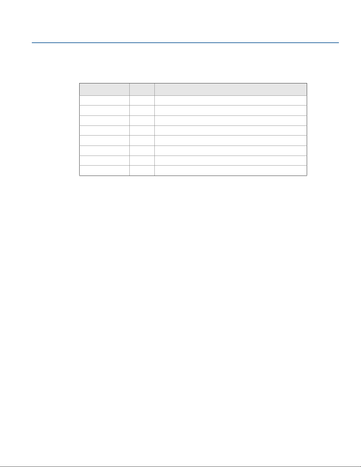
Table 1-1. Installation drawings for the Rosemount 2240 Multi-Input Temperature Transmitter
Drawing Issue Title
D9240 041-912 2 Mechanical Installation Drawing
D9240 041-959 4 Electrical Installation Drawing
D7000 001-798 2 System Installation Drawing Foundation fieldbus FISCO
D7000 001-811 1 System Installation Drawing Foundation fieldbus IS Entity
D7000 005-451 2 Type 614 wiring
D9261 085-035 3 General arrangement - Leak detection temperature sensors
D9261 085-036 3 General arrangement - Cool down temperature sensors
D9261 085-039 2 Rosemount 2240/614 accessory conical connection
Reference Manual
00809-0100-2240, Rev EA
4
Introduction
Page 17
Reference Manual
S
E
P
A
R
A
T
E
S
T
E
E
L
&
P
L
A
S
T
I
C
00809-0100-2240, Rev EA
1.4 Service support
For service support contact the nearest Emerson Automation Solutions/Rosemount Tank Gauging representative. Contact information can be found on the web site Emerson Automation Solutions/Rosemount
Tank Gauging.
1.5 Product recycling/disposal
Recycling of equipment and packaging should be taken into consideration and disposed of in accordance
with local and national legislation/regulations.
The label below is put on Rosemount Tank Gauging products as a recommendation to customers if
scrapping is considered.
Recycling or disposal should be done following instructions for correct separation of materials when
breaking up the units.
Figure 1-1. A green label is placed on the transmitter housing
Introduction
May 2020
Introduction
5
Page 18

Introduction
May 2020
1.6 Packing material
Rosemount Tank Radar AB is fully certified according to ISO 14001 environmental standards. By recycling
the corrugated paperboard, or wooden boxes, used for shipping our products you can contribute to take
care of the environment.
1.6.1 Reuse and recycling
Experience has shown that wooden boxes can be used several times for various purposes. After careful
disassembly the wooden parts may be reused. Metal waste may be converted.
1.6.2 Energy recovery
Products which have served their time may be divided into wood and metal components and the wood
can be used as fuel in sufficient ovens.
Due to its low moisture content (approximately 7%) this fuel has a higher calorific value than ordinary
wood fuel (moisture content approximately 20%).
When burning interior plywood the nitrogen in the adhesives may increase emissions of nitrogen oxides
to the air 3-4 times more than when burning bark and splinter.
Reference Manual
00809-0100-2240, Rev EA
Note
Landfill is not a recycling option and should be avoided.
6
Introduction
Page 19
Reference Manual
Rosemount
TankMaster
Rosemount 2410 Tank Hub
Modem
Rosemount 2460
System Hub
Relay Outputs
Secondary Bus (Non-IS)
Primary Bus
Tankbus
Rosemount 2240S
Temperature
Transmitter
Rosemount 2230
Graphical Field
Host
Zone 1
Zone 0
Rosemount 5900S
Radar Level Gauge
Secondary bus (IS)
Servo
gauges
00809-0100-2240, Rev EA
Section 2 Overview
Introduction . . . . . . . . . . . . . . . . . . . . . . . . . . . . . . . . . . . . . . . . . . . . . . . . . . . . . . . . . . . . . . . . . . . . . page 7
Components . . . . . . . . . . . . . . . . . . . . . . . . . . . . . . . . . . . . . . . . . . . . . . . . . . . . . . . . . . . . . . . . . . . . . page 8
System overview . . . . . . . . . . . . . . . . . . . . . . . . . . . . . . . . . . . . . . . . . . . . . . . . . . . . . . . . . . . . . . . . . page 9
Getting started . . . . . . . . . . . . . . . . . . . . . . . . . . . . . . . . . . . . . . . . . . . . . . . . . . . . . . . . . . . . . . . . . . . page 17
Installation procedure . . . . . . . . . . . . . . . . . . . . . . . . . . . . . . . . . . . . . . . . . . . . . . . . . . . . . . . . . . . . . page 18
2.1 Introduction
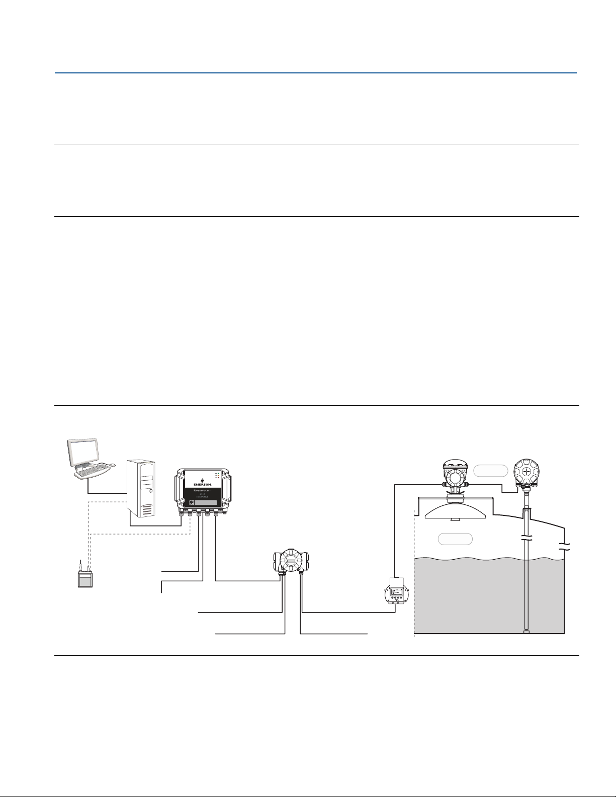
The Rosemount™ 2240S Multi-input Temperature Transmitter can connect up to sixteen 3- or 4-wire
temperature spot elements and an integrated water level sensor. The Rosemount 2240S sends
measurement data, such as temperature and water level, via the intrinsically safe 2-wire Tankbus
Rosemount 2410 Tank Hub. Measurement data and status information can be viewed on a PC with the
Rosemount TankMaster software, as well as on the integral display of the tank hub and the Rosemount
2230 Graphical Field Display.
Data from a group of tanks is buffered by a Rosemount 2460 System Hub, and is distributed to a
Rosemount TankMaster PC, or another host system, whenever the system hub receives a request for
data. In case no system hub is included in the system, the tank hub can communicate directly with the
host computer.
Overview
May 2020
(1)
, to a
Figure 2-1. System integration
1. The intrinsically safe Tankbus complies with the FISCO FOUNDATION™ fieldbus standard.
Overview
7
Page 20
Overview
A
B
C
D
E
F
May 2020
2.2 Components
Reference Manual
00809-0100-2240, Rev EA
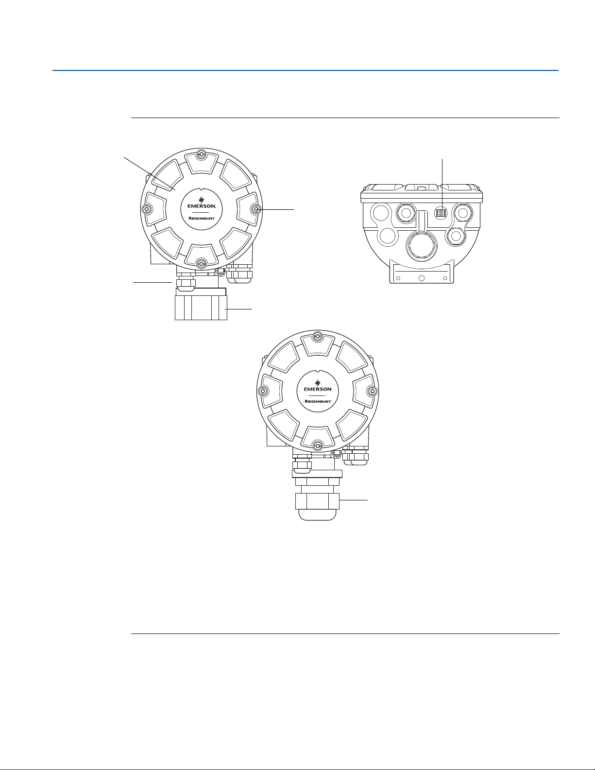
Figure 2-2. Rosemount 2240S components
A. Cover.
B. Entries (x 3) of type ½ - 14 NPT.
C. Lock nut for connection of Multi Spot Temperature sensor and Water Level Sensors (MST/WLS).
D. Cover screws (x 4).
E. External ground screw.
F. M32 Cable gland (option for remote mounting).
8
Overview
Page 21

Reference Manual
00809-0100-2240, Rev EA
2.3 System overview
The Rosemount Tank Gauging system is a state-of-the art inventory and custody transfer radar tank level
gauging system. It is developed for a wide range of applications at refineries, tank farms and fuel depots,
and fulfills the highest requirements on performance and safety.
Overview
May 2020
The field devices on the tank communicate over the intrinsically safe Tankbus. The Tankbus is based on a
standardized fieldbus, the FISCO
supporting that protocol. By utilizing a bus powered 2-wire intrinsically safe fieldbus the power
consumption is minimized. The standardized fieldbus also enables integration of other vendors’
equipment on the tank.
The Rosemount Tank Gauging product portfolio includes a wide range of components to build small or
large customized tank gauging systems. The system includes various devices, such as radar level gauges,
temperature transmitters, and pressure transmitters for complete inventory control. Such systems are
easily expanded thanks to the modular design.
The Rosemount Tank Gauging system is a versatile system that is compatible with and can emulate all
major tank gauging systems. Moreover, the well-proven emulation capability enables step-by-step
modernization of a tank farm, from level gauges to control room solutions.
It is possible to replace old mechanical or servo gauges with modern Rosemount Tank Gauging devices,
without replacing the control system or field cabling. It is further possible to replace old HMI/SCADA-systems and field communication devices without replacing the old gauges.
There is a distributed intelligence in the various system units which continuously collect and process
measurement data and status information. When a request for information is received an immediate
response is sent with updated information.
The flexible Rosemount Tank Gauging system supports several combinations to achieve redundancy,
from control room to the different field devices. Redundant network configuration can be achieved at all
levels by doubling each unit and using multiple control room work stations.
(1)
FOUNDATION™ fieldbus, and allows integration of any device
1. See documents IEC 61158-2 and IEC/TS 60079-27
Overview
9
Page 22
Overview
Rosemount 2230
Display
Rosemount 2240S
Temperature Transmitter
Rosemount 5900S
Radar Level Gauge
Tankbus
Rosemount 5300
Level Transmitter
Rosemount 5408
Level Transmitter
Rosemount 3051S
Pressure Transmitter
TRL2 Modbus
Rosemount 2180
Field Bus Modem
Rosemount 2460 System Hub
Rosemount
TankMaster PC
Plant Host Computer
Rosemount 644
644
Plant Host Computer
NON-HAZARDOUS AREA HAZARDOUS AREA
Rosemount 2410 Tank Hub
Rosemount 5900S
Radar Level Gauge
Tankbus
Segment coupler
CUSTODY TRANSFER / INVENTORY TANK GAUGINGOPERATIONAL CONTROL
Rosemount 644
Temperature
Transmitter
Rosemount 2410 Tank Hub
Rosemount 2410 Tank Hub
Rosemount 2240S
Temperature Transmitter
Rosemount
TankMaster PC
Rosemount 644
Rosemount 2230 Display
Ethernet
May 2020
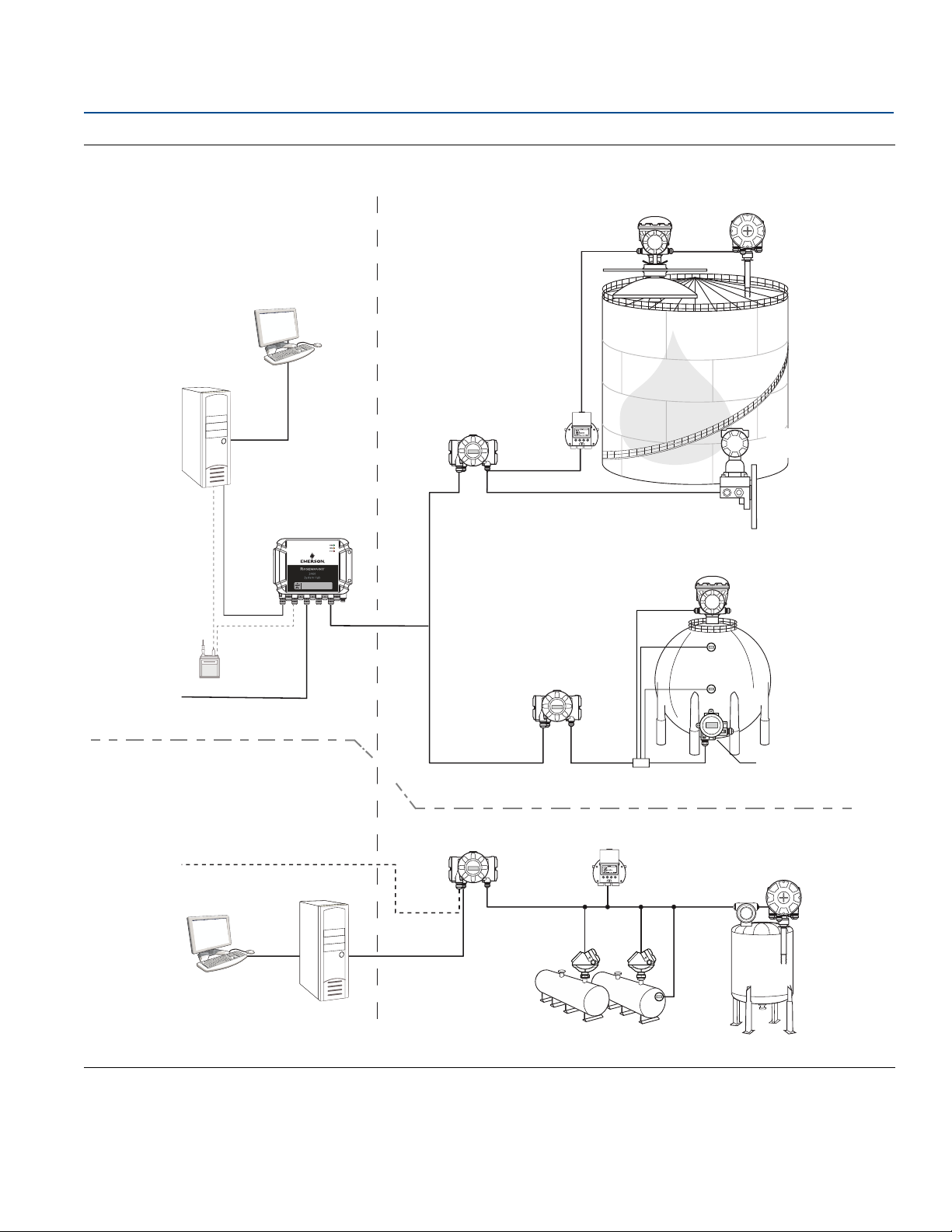
Figure 2-3. Rosemount Tank Gauging System Architecture
Reference Manual
00809-0100-2240, Rev EA
Overview
10
Page 23
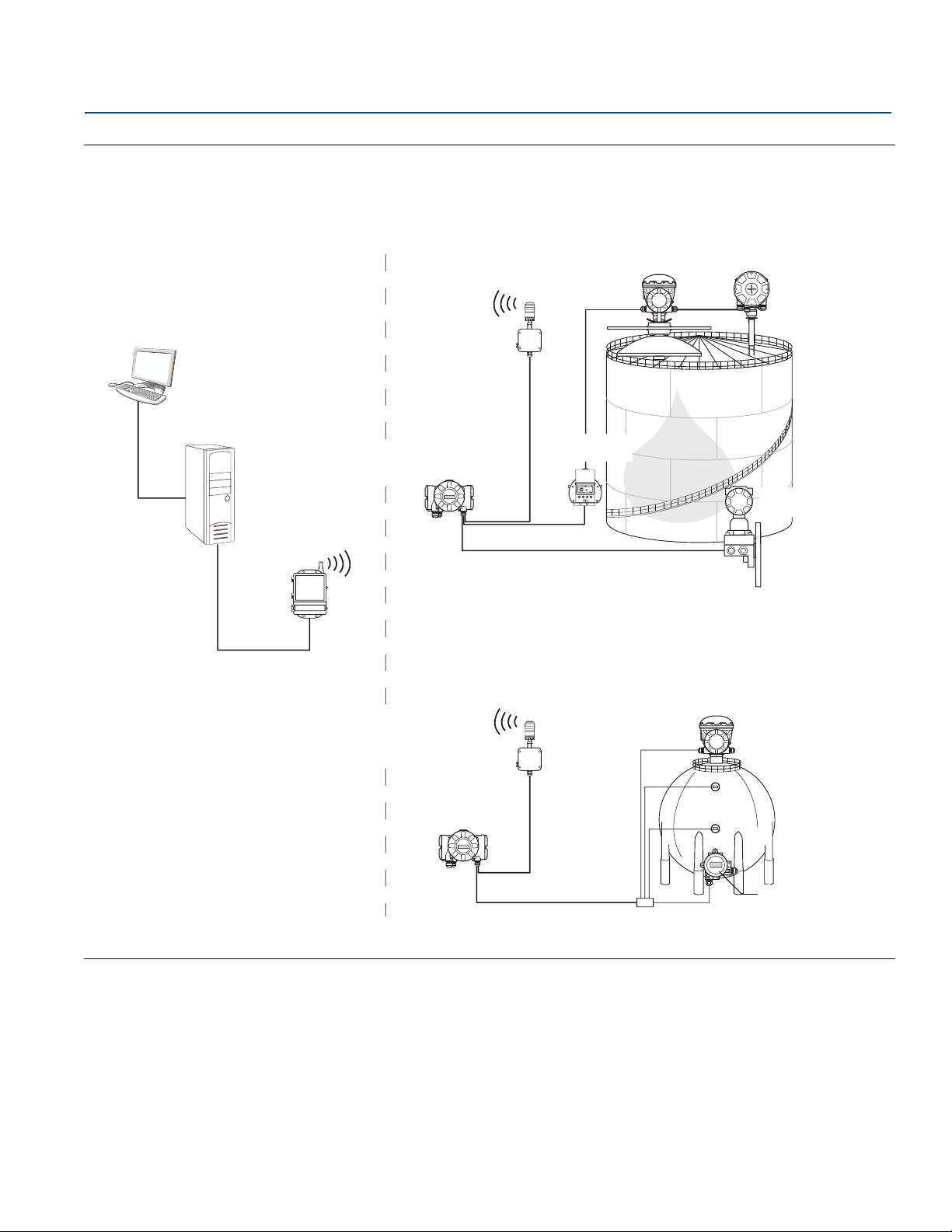
Reference Manual
NON-HAZARDOUS AREA HAZARDOUS AREA
Emerson Wireless
Gateway
Tankbus
Segment coupler
Emerson Wireless
775 THUM Adapter
Rosemount 5900S
Radar Level Gauge
Rosemount 2240S
Temperature Transmitter
Rosemount 2230
Display
Rosemount 3051S
Pressure Transmitter
Rosemount 2410 Tank Hub
Rosemount 5900S
Radar Level Gauge
Rosemount
TankMaster PC
Rosemount 644
Temperature Transmitter
Rosemount 644
Rosemount 644
Emerson Wireless
775 THUM Adapter
Rosemount 2410 Tank Hub
00809-0100-2240, Rev EA
Figure 2-4. Rosemount Tank Gauging System Architecture for Wireless Systems
Overview
May 2020
Overview
11
Page 24
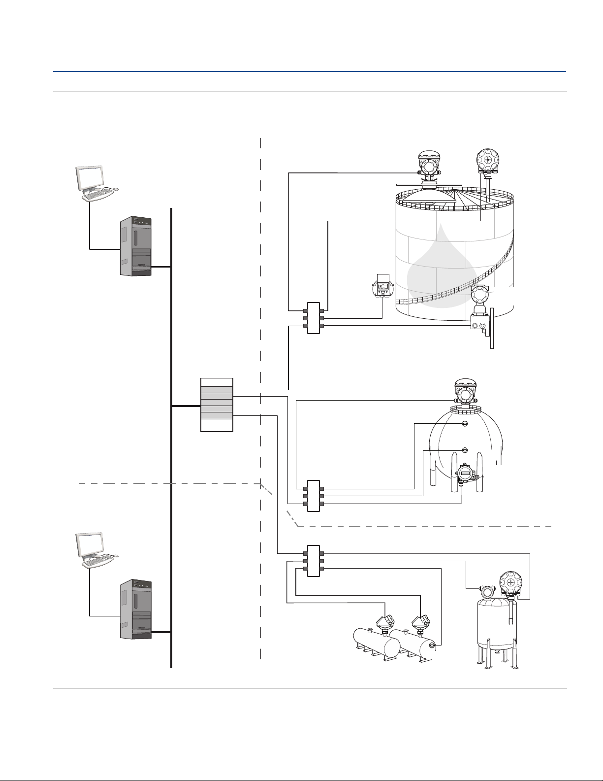
Overview
NON-HAZARDOUS AREA HAZARDOUS AREA
CUSTODY TRANSFER
INVENTORY TANK GAUGING
OPERATIONAL CONTROL
PC
644
644
Segment coupler
Segment coupler
FOUNDATION Fieldbus
Power Supply
Rosemount 644
PC
Rosemount 5900S
Radar Level
Rosemount 2240S
Temperature Transmitter
Rosemount 3051S
Pressure Transmitter
Rosemount 5900S
Radar Level Gauge
Rosemount 644
Temperature
Transmitter
Rosemount 5300
Level Transmitter
Rosemount 5408
Rosemount 2240S
Rosemount 2230 Display
May 2020
Figure 2-5. Rosemount Tank Gauging System Architecture in a FOUNDATION Fieldbus Network
Reference Manual
00809-0100-2240, Rev EA
12
Overview
Page 25
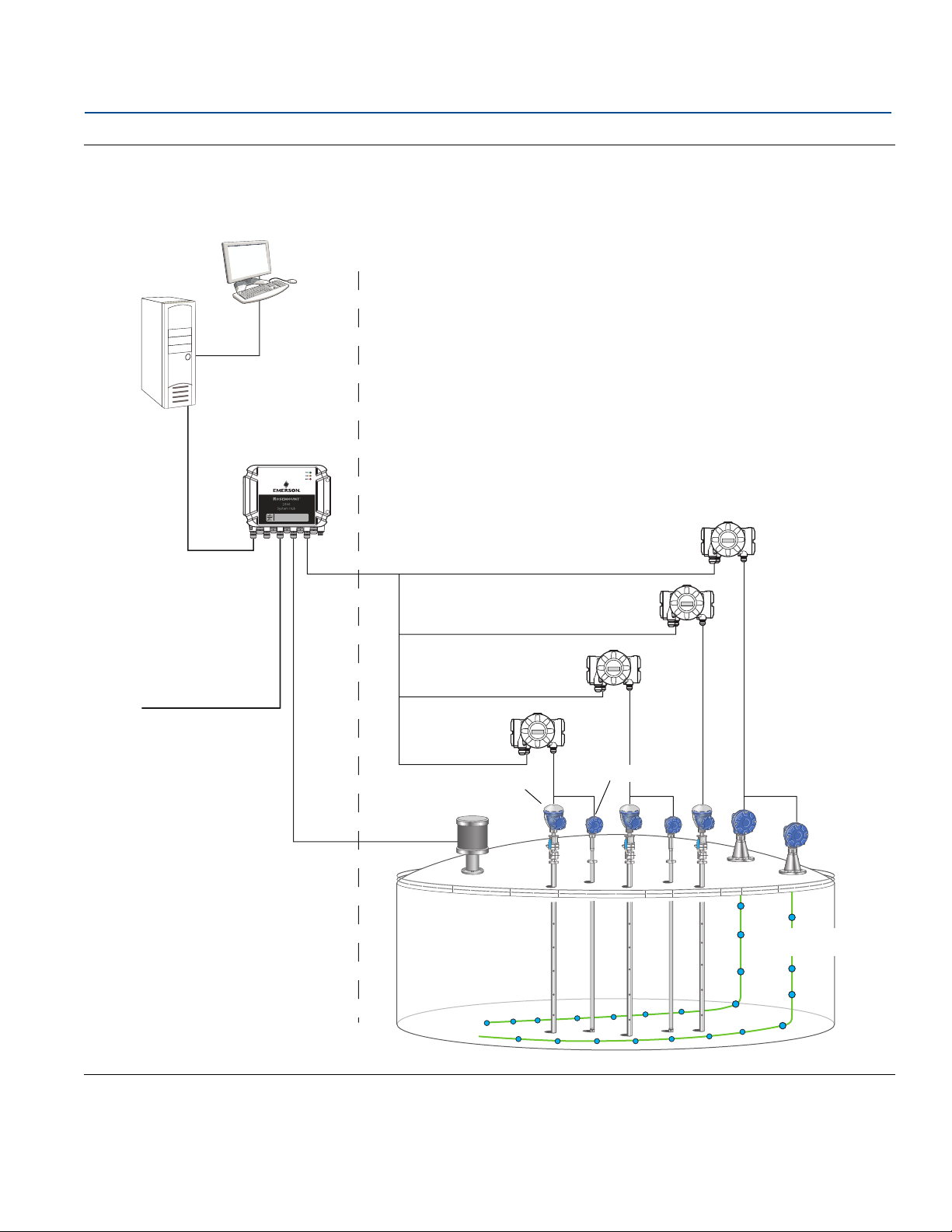
Reference Manual
TRL2 Modbus
Rosemount 2460 System Hub
Rosemount
TankMaster PC
Plant Host Computer
NON-HAZARDOUS AREA HAZARDOUS AREA
Rosemount 2410 Tank Hub
Rosemount 2240S
Temperature Transmitters
Ethernet
Rosemount 614
Temperature Sensor
LTD
Tankbus
Rosemount 5900S
Rosemount 2240S
00809-0100-2240, Rev EA
Figure 2-6. LNG Tank in Rosemount Tank Gauging System
Overview
May 2020
Overview
13
Page 26

Overview
May 2020
Reference Manual
00809-0100-2240, Rev EA
TankMaster HMI Software
Rosemount TankMaster is a powerful Windows-based Human Machine Interface (HMI) for complete tank
inventory management. It provides configuration, service, set-up, inventory, and custody transfer
functions for Rosemount Tank Gauging systems and other supported instruments.
TankMaster is designed to be used in the Microsoft
measurement data from your Local Area Network (LAN).
The TankMaster WinOpi program lets the operator monitor measured tank data. It includes alarm
handling, batch reports, automatic report handling, historical data sampling as well as inventory
calculations such as Volume, Observed Density and other parameters. A plant host computer can be
connected for further processing of data.
The TankMaster WinSetup program is a graphical user interface for installation, configuration and service
of devices in the Rosemount Tank Gauging system.
®
Windows environment providing easy access to
Rosemount 2460 System Hub
The Rosemount 2460 System Hub is a data concentrator that continuously polls and stores data from
field devices such as radar level gauges and temperature transmitters in a buffer memory. Whenever a
request for data is received, the system hub can immediately send data from the updated buffer memory
for a group of tanks.
Measured and calculated data from one or more tanks is communicated via the Rosemount 2410 Tank
Hub to the system hub buffer memory. Whenever a request is received, the system hub can immediately
send data from a group of tanks to a TankMaster PC, or a host.
The Rosemount 2460 can be used to connect devices from other vendors as well, such as Honeywell
Enraf and Whessoe.
The Rosemount 2460 has eight slots for communication interface boards. These boards can be
individually configured for communication with hosts or field devices. They can be ordered for various
interfaces, for example TRL2, RS485, Enraf BPM, and Whessoe 0-20 mA/RS485 communication. Two
slots can also be configured for RS232 communication.
One of the system hub’s three Ethernet ports is used for Modbus TCP connection to host systems. By
simply connecting the system hub to the existing LAN network, communication over Ethernet is
established.
The system hub can provide redundancy for critical operations, by using two identical devices. The
primary system hub is active and the other one is in passive mode. If the primary unit stops working
properly, the secondary unit is activated and a failure message is sent to TankMaster (or a DCS system).
®
14
Overview
Page 27

Reference Manual
00809-0100-2240, Rev EA
Rosemount 2410 Tank Hub
The Rosemount 2410 Tank Hub acts as a power supply to the connected field devices in the hazardous
area using the intrinsically safe Tankbus.
The tank hub collects measurement data and status information from field devices on a tank. It has two
external buses for communication with various host systems.
There are two versions of the Rosemount 2410 Tank Hub; one for single tank operation and one for
multiple tanks operation. The multiple tanks version of the Rosemount 2410 supports up to 10 tanks
and 16 devices. With the Rosemount 5300 the Rosemount 2410 supports up to 5 tanks.
The Rosemount 2410 is equipped with two relays which support configuration of up to 10 “virtual” relay
functions allowing you to specify several source signals for each relay.
The Rosemount 2410 supports Intrinsically Safe (IS) and Non-Intrinsically Safe (Non-IS) analog 4-20 mA
inputs/outputs. By connecting an Emerson
output, the tank hub is capable of wireless communication with an Emerson Wireless Gateway in a
WirelessHART
Rosemount 5900S Radar Level Gauge
The Rosemount 5900S Radar Level Gauge is an intelligent instrument for measuring the product level
inside a tank. Different antennas can be used in order to meet the requirements of different applications.
The Rosemount 5900S can measure the level of almost any product, including bitumen, crude oil,
refined products, aggressive chemicals, LPG and LNG.
®
network.
Overview
May 2020
™
Wireless 775 THUM™ Adapter to the IS HART 4-20 mA
The Rosemount 5900S sends microwaves towards the surface of the product in the tank. The level is
calculated based on the echo from the surface. No part of the Rosemount 5900S is in actual contact with
the product in the tank, and the antenna is the only part of the gauge that is exposed to the tank
atmosphere.
The 2-in-1 version of the Rosemount 5900S Radar Level Gauge has two radar modules in the same
transmitter housing allowing two independent level measurements using one antenna and one tank
opening.
Rosemount 5300 Guided Wave Radar
The Rosemount 5300 is a premium 2-wire guided wave radar for level measurements on liquids, to be
used in a wide range of medium accuracy applications under various tank conditions. Rosemount 5300
includes the Rosemount 5301 for liquid level measurements and the Rosemount 5302 for liquid level and
interface measurements.
Rosemount 5408 Radar Level Transmitter
The Rosemount 5408 is a non-contacting level transmitter for accurate and reliable level measurement
on small storage and buffer tanks.
The Rosemount 5408 provides accurate and reliable level measurements for metallic and non-metallic
vessels. It is suitable for almost any liquid and is ideal for challenging applications with agitators, foam,
high temperatures, and pressures. It is also an excellent choice for level measurement in tanks with small
diameter (2- to 4-inch) stiling wells.
The narrow beam makes the Rosemount 5408 the ideal solution for bulk solids in small to medium sized
silos with rapid level changes.
Overview
Rosemount 2240S Multi-Input Temperature Transmitter
The Rosemount 2240S Multi-input Temperature Transmitter can connect up to 16 temperature spot
sensors and an integrated water level sensor.
15
Page 28

Overview
May 2020
Reference Manual
00809-0100-2240, Rev EA
Rosemount 2230 Graphical Field Display
The Rosemount 2230 Graphical Field Display presents inventory tank gauging data such as level,
temperature, and pressure. The four softkeys allow you to navigate through the different menus to
provide all tank data, directly in the field. The Rosemount 2230 supports up to 10 tanks. Up to three
Rosemount 2230 displays can be used on a single tank.
Rosemount 644 Temperature Transmitter
The Rosemount 644 is used with single spot temperature sensors.
Rosemount 565/566/765 Multiple Spot Temperature Sensors
These multiple spot sensors offer precise measurements for liquid temperature in a wide range of
applications. The Rosemount 565 provides a temperature profile by using up to sixteen Pt-100 spot
elements. The Rosemount 566 is used for cryogenic applications. The Rosemount 765 has an integrated
water level sensor available in open and closed versions for crude oil and lighter fuels, respectively.
Rosemount 614 Cryogenic Spot Temperature Sensor
The Rosemount 614 Cryogenic Spot Temperature Sensor is designed for temperature measurements in
cryogenic and refrigerated full containment storage tanks. It is used with Rosemount 2240S Multi-Input
Temperature Transmitters for applications such as leak detection between inner and outer tank, as well
as skin temperature and/or cool-down monitoring.
The spot elements are wired through a mineral-insulated flexible steel cable up to 300 m (980 ft). This
allows temperature measurements inside a full containment tank during the cool-down procedure and
for leak detection and corner protection in the insulation space.
Rosemount 614 temperature sensors are easily integrated through a conical connection or a junction
box to the Rosemount 2240S Multi-input Temperature Transmitter. Each 2240S Transmitter supports up
to 16 Rosemount 614 temperature sensors.
Rosemount 3051S Pressure Transmitter
The Rosemount 3051S series consists of transmitters and flanges suitable for all kinds of applications,
including crude oil tanks, pressurized tanks and tanks with / without floating roofs.
By using a Rosemount 3051S Pressure Transmitter near the bottom of the tank as a complement to a
Rosemount 5900S Radar Level Gauge, the density of the product can be calculated and presented. One
or more pressure transmitters with different scalings can be used on the same tank to measure vapor
and liquid pressure.
Rosemount 2180 Field Bus Modem
The Rosemount 2180 Field Bus Modem (FBM) is used for connecting a TankMaster PC to the TRL2
communication bus. The Rosemount 2180 is connected to the PC using either the USB or the RS232
interface.
Emerson Wireless Gateway and Emerson Wireless 775 THUM™
Adapter
16
An Emerson Wireless 775 THUM Adapter allows wireless communication between a Rosemount 2410
Tank Hub and an Emerson Wireless Gateway. The gateway is the network manager that provides an
interface between field devices and the TankMaster inventory software or host / DCS systems.
See the Rosemount Tank Gauging System Data Sheet (Document No. 00813-0100-5100) for more
information on the various devices and options.
Overview
Page 29

Reference Manual
00809-0100-2240, Rev EA
2.4 Getting started
To start up a Rosemount Tank Gauging system do the following:
1. Install the TankMaster software on the control room PC.
2. Prepare the start-up by recording the information that will be needed for configuration of the various
devices as described in the Rosemount Tank Gauging System Configuration Manual
3. Connect the Rosemount 2460 System Hub to the TankMaster PC. The system hub may be connected
via Modbus TCP, a Rosemount 2180 Field Bus Modem, or directly via RS232 or RS485 interface.
4. Connect the Rosemount 2410 Tank Hub to the Rosemount 2460 System Hub.
5. Connect the field devices, such as a Rosemount 5900S Radar Level Gauge and a Rosemount 2240S
Multi-input Temperature Transmitter, to the Rosemount 2410 Tank Hub via the Tankbus.
6. Configure the Rosemount 2460 System Hub (if included in the system) by using the TankMaster
WinSetup configuration software.
7. Configure the Rosemount 2410 Tank Hub by using the TankMaster WinSetup configuration software.
8. Configure field devices, such as the Rosemount 5900S and the Rosemount 2240S, by using the
TankMaster WinSetup configuration software.
Overview
May 2020
.
To start up Rosemount Tank Gauging devices in a F
1. Prepare the start-up by recording the information that will be needed for configuration of the various
field devices as described in the Rosemount Tank Gauging System Configuration Manual
2. Connect the field devices, such as the Rosemount 5900S Radar Level Gauge and Rosemount 2240S
Multi-input Temperature Transmitter, to the F
3. Configure the field devices by using the AMS Device Manager.
See see the Rosemount Tank Gauging System Configuration Manual
configure the various Rosemount Tank Gauging devices.
OUNDATION fieldbus system:
.
OUNDATION fieldbus network.
for more information on how to
Overview
17
Page 30
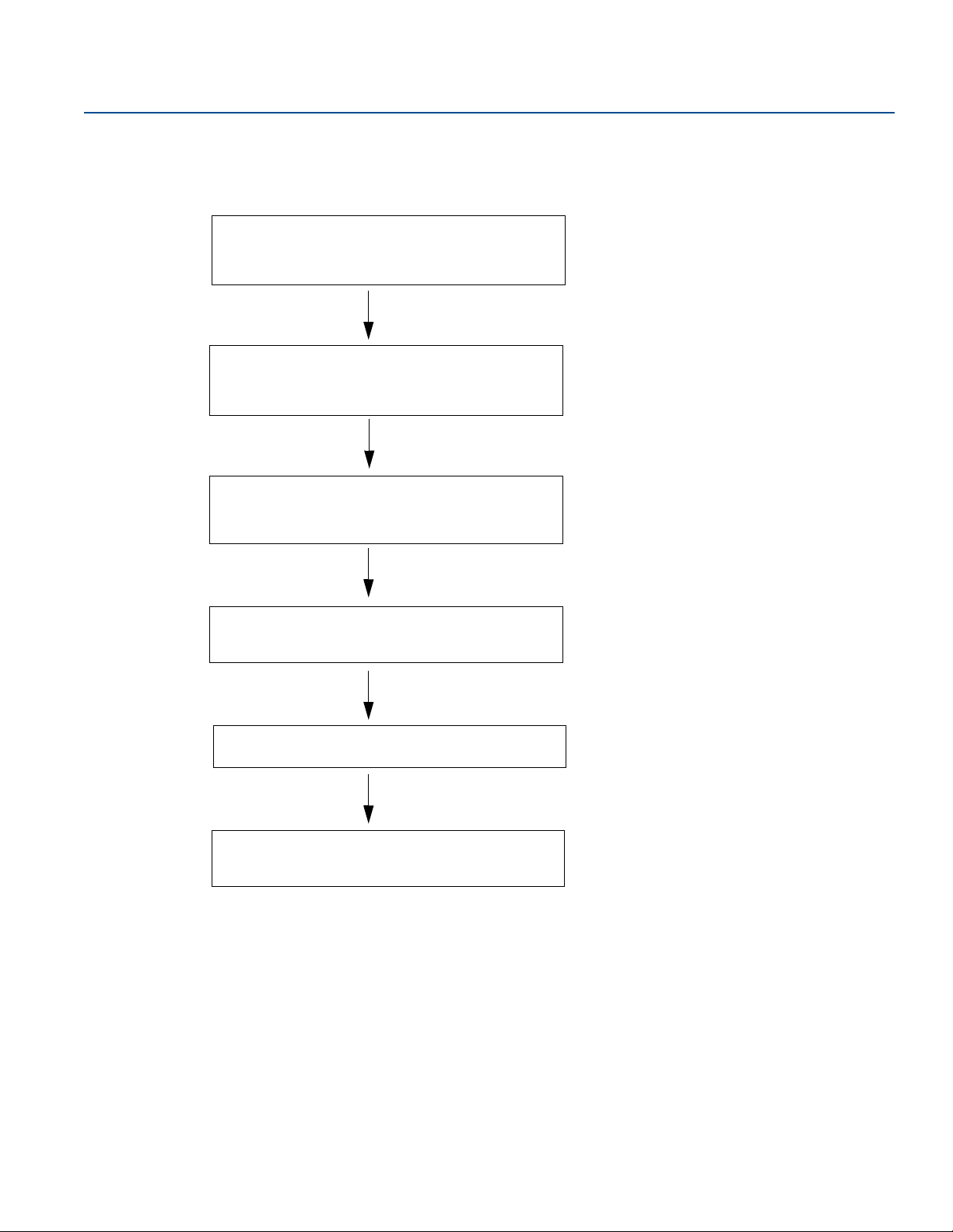
Overview
2. Review mounting considerations for the 2240S
(“Installation considerations” on page 30).
5. Power up the 2240S transmitter.
4. Wire the 2240S transmitter
(“Electrical installation” on page 37).
3. Install the 2240S transmitter
(“Mechanical installation” on page 31).
1. Install the temperature sensor/WLS
(Section 3: Sensor Installation).
6. Configure the 2240S transmitter.
(Section 5: Configuration/Operation).
May 2020
2.5 Installation procedure
Follow these steps for proper installation of the Rosemount 2240S:
Reference Manual
00809-0100-2240, Rev EA
18
Overview
Page 31
Reference Manual
00809-0100-2240, Rev EA
Section 3 Sensor Installation
Safety messages . . . . . . . . . . . . . . . . . . . . . . . . . . . . . . . . . . . . . . . . . . . . . . . . . . . . . . . . . . . . . . . . . . page 19
Installation considerations . . . . . . . . . . . . . . . . . . . . . . . . . . . . . . . . . . . . . . . . . . . . . . . . . . . . . . . . . page 20
Multiple Spot Temperature sensor . . . . . . . . . . . . . . . . . . . . . . . . . . . . . . . . . . . . . . . . . . . . . . . . . . page 21
Water Level Sensor . . . . . . . . . . . . . . . . . . . . . . . . . . . . . . . . . . . . . . . . . . . . . . . . . . . . . . . . . . . . . . . page 24
Installing a temperature sensor tube . . . . . . . . . . . . . . . . . . . . . . . . . . . . . . . . . . . . . . . . . . . . . . . . page 25
Rosemount 614 Cryogenic Spot Temperature Sensor . . . . . . . . . . . . . . . . . . . . . . . . . . . . . . . . . page 26
3.1 Safety messages
Procedures and instructions in this section may require special precautions to ensure the safety of the
personnel performing the operations. Information that raises potential safety issues is indicated by a
warning symbol ( ). Please refer to the following safety messages before performing an operation
preceded by this symbol.
Sensor Installation
May 2020
Failure to follow safe installation and servicing guidelines could result in death or serious injury.
Make sure only qualified personnel perform the installation.
Use the equipment only as specified in this manual. Failure to do so may impair the protection provided
by the equipment.
Do not perform any service other than those contained in this manual unless you are qualified.
To prevent ignition of flammable or combustible atmospheres, disconnect power before servicing.
Substitution of components may impair Intrinsic Safety.
Explosions could result in death or serious injury.
Verify that the operating environment of the transmitter is consistent with the appropriate hazardous
locations certifications.
Before connecting a handheld communicator in an explosive atmosphere, make sure the instruments in
the loop are installed in accordance with intrinsically safe or non-incendive field wiring practices.
Do not remove the gauge cover in explosive atmospheres when the circuit is alive.
High voltage that may be present on leads could cause electrical shock.
Avoid contact with leads and terminals.
Make sure the main power to the Rosemount
sources are disconnected or not powered while wiring the gauge.
™
2240S is off and the lines to any other external power
Sensor Installation
19
Page 32

Sensor Installation
May 2020
3.2 Installation considerations
A Multiple Spot Temperature sensor (MST) and Water Level Sensor (WLS) must be installed on the tank
before installing the Rosemount 2240S Multi-input Temperature Transmitter.
The MST/WLS is normally anchored to the bottom of the tank by attaching a weight at the end of the
tube. A tank expands when it is filled or warmed up, causing the roof to move slightly upwards. The
weight has a shackle which allows the tube to follow the expansion.
Multiple Spot Temperature sensor (MST)
Be careful with the flexible protection tube
Temperature and Water Level Sensors should be located as far away as possible from heating coils and
mixers.
In case the flexible tube is damaged, please contact Emerson Automation Solutions/Rosemount Tank
Gauging.
Do not attempt to fix or rebuild the temperature sensor since this may cause serious malfunctions
Water Level Sensor
Handle the Water Level Sensor carefully
Leave the sensor protection on until the final positioning in the tank
Reference Manual
00809-0100-2240, Rev EA
20
Sensor Installation
Page 33
Reference Manual
Maximum product level
Recommended:
0.5 to 1 m
(1.6 to 3.3 ft)
below maximum
filling level
Upper spot
element
First spot
element
2-15 kg
(4.4-33 lbs)
150-350 mm
(5.9 -13.8 in.)
Anchor weight
Min. 1 m (3.3 ft)
00809-0100-2240, Rev EA
3.3 Multiple Spot Temperature sensor
A Multiple Spot Temperature sensor (MST) typically measures the temperature with a number of Pt100
elements placed at different heights to provide a temperature profile and average temperature of the
product. The spot elements are placed in a flexible gas tight tube made of stainless steel which can be
anchored to the tank bottom, see “Installing a temperature sensor tube” on page 25.
Up to 16 Pt100 temperature elements can be connected to a Rosemount 2240S Multi-input
Temperature Transmitter.
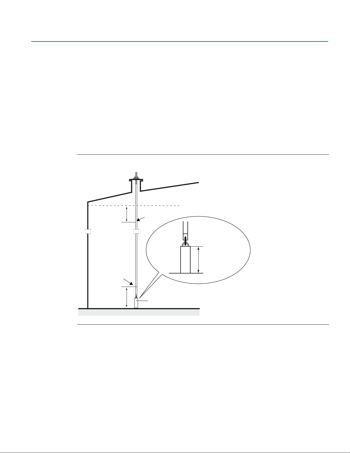
3.3.1 Installation on fixed roof tanks
On fixed roof tanks the MST is attached to a flange mounted on a suitable nozzle.
Figure 3-1. Installation of multiple spot temperature elements on fixed roof tanks
Sensor Installation
May 2020
Sensor Installation
21
Page 34
Sensor Installation
Maximum level
Upper spot
element
First spot
element
2-15 kg
(4.4-33 lbs)
100 mm
(3.9 in.)
Min. 1 m (3.3 ft)
Min. 1 m (3.3 ft)
May 2020
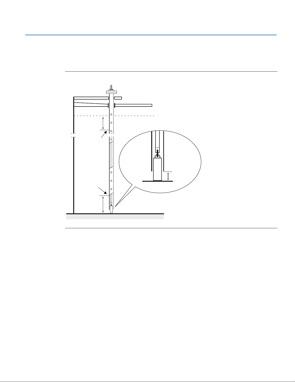
3.3.2 Installation on floating roof tanks
On floating roof tanks the temperature elements can be mounted in a still-pipe as illustrated in
Figure 3-2 or in other suitable roof openings.
Figure 3-2. Installation of multiple spot temperature elements in still-pipe
Reference Manual
00809-0100-2240, Rev EA
22
Sensor Installation
Page 35
Reference Manual
Minimum level
Tank Zero Level
Min. 1 m
(3.3 ft)
Min. 1 m
(3.3 ft)
00809-0100-2240, Rev EA
3.3.3 Custody transfer applications
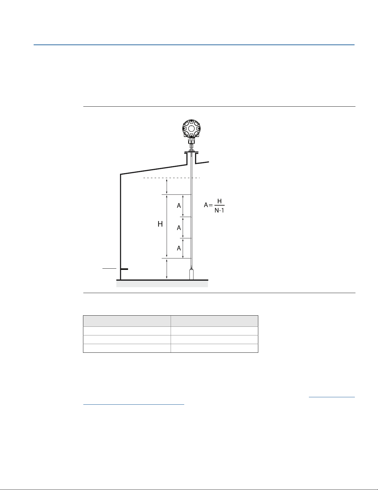
For Custody Transfer applications, API chapter 7 recommends a minimum of one temperature element
per 3 meters (10 feet) as illustrated in Figure 3-3. Emerson Automation Solutions/Rosemount Tank Gauging
may in some cases recommend even more temperature elements for Custody Transfer tanks, depending
on how the tanks are operated.
Figure 3-3. Recommended position of temperature elements for Custody Transfer applications
Sensor Installation
May 2020
Sensor Installation
Table 3-1. Number of spot sensors for various tube lengths
Tube length Number of temp. elements
< 9 m
9 - 15 m 5
> 15 m 6
4
Example
5 spot sensors and H=10 m.
A=10/(5-1)=2.5 m.
The position of a temperature element is measured from the Tank Zero Level. See the Rosemount Tank
Gauging System Configuration Manual for more information about how to use the TankMaster WinSetup
software to configure temperature elements for average temperature calculations.
23
Page 36
Sensor Installation
Upper Sensor Limit (100%)
Lower Sensor Limit (0%)
WLS Probe Active Length
Standard: 500 mm (19.7 in.)
Option: 1000 mm (39.4 in.)
Recommended minimum distance: 1 m ( 3.3 ft)
Weight
350 mm
(13.8 in.)
Nuts to adjust
vertical position of
the sensor probe
May 2020
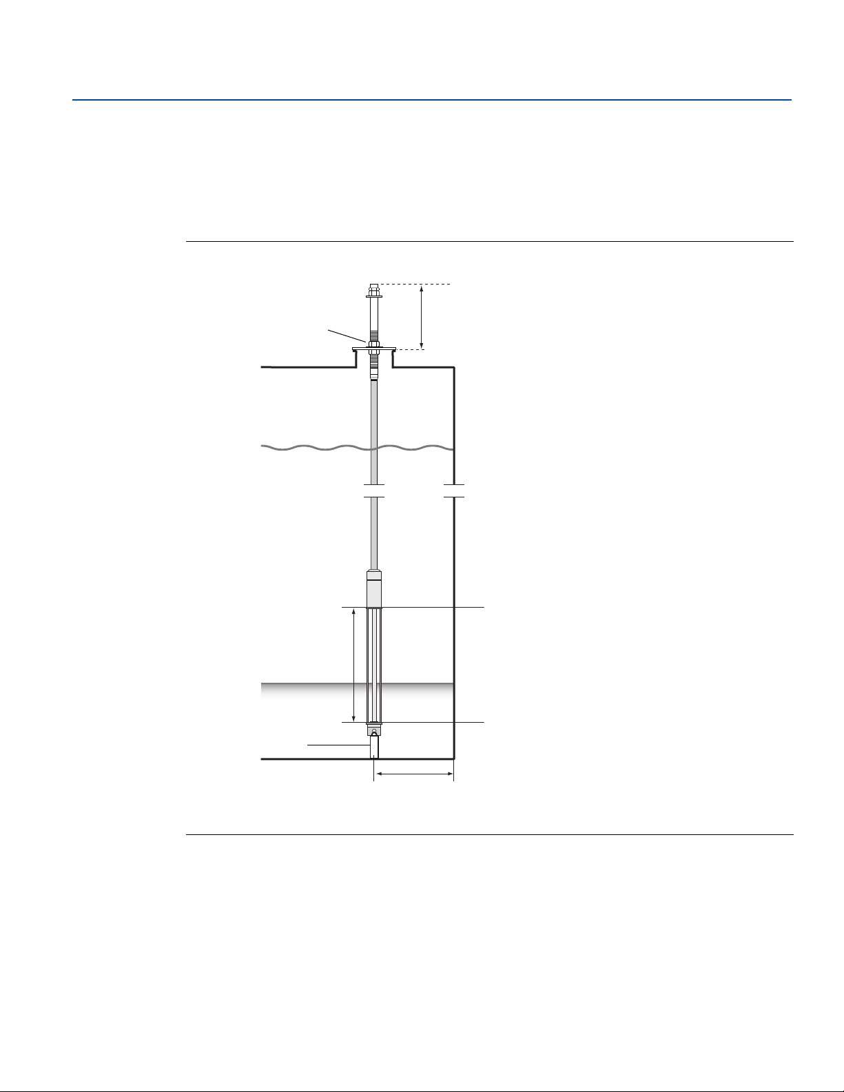
3.4 Water Level Sensor
The water level sensor (WLS) probe, with integrated temperature elements, is attached at the lower end
of the flexible protection tube. A weight is attached to stabilize the tube as illustrated in Figure 3-4. At
the upper part of the sensor probe, nuts are placed at the middle of the threaded section, 350 mm below
the top of the probe. This is intended as a starting point for adjusting the vertical position of the probe.
Figure 3-4. Water Level Sensor with integrated temperature sensors
Reference Manual
00809-0100-2240, Rev EA
As an option, the tube may be stabilized by putting a concentric weight above the WLS probe, instead of
at the end, in order to ensure that measurements are performed as close to the tank bottom as possible.
Also, the eyebolt at the end of the tube can be removed.
See also “Water Level Sensor calibration” on page 57 and “Water Level Sensor measuring range” on
page 59 for more information on how to calibrate and configure the water level sensor.
24
Sensor Installation
Page 37
Reference Manual
Lock nut
Tube
Anchor
weight
Threads
Lock nut
2-15 kg
(4.4-33 lbs)
150-350 mm
(5.9-13.8 in.)
00809-0100-2240, Rev EA
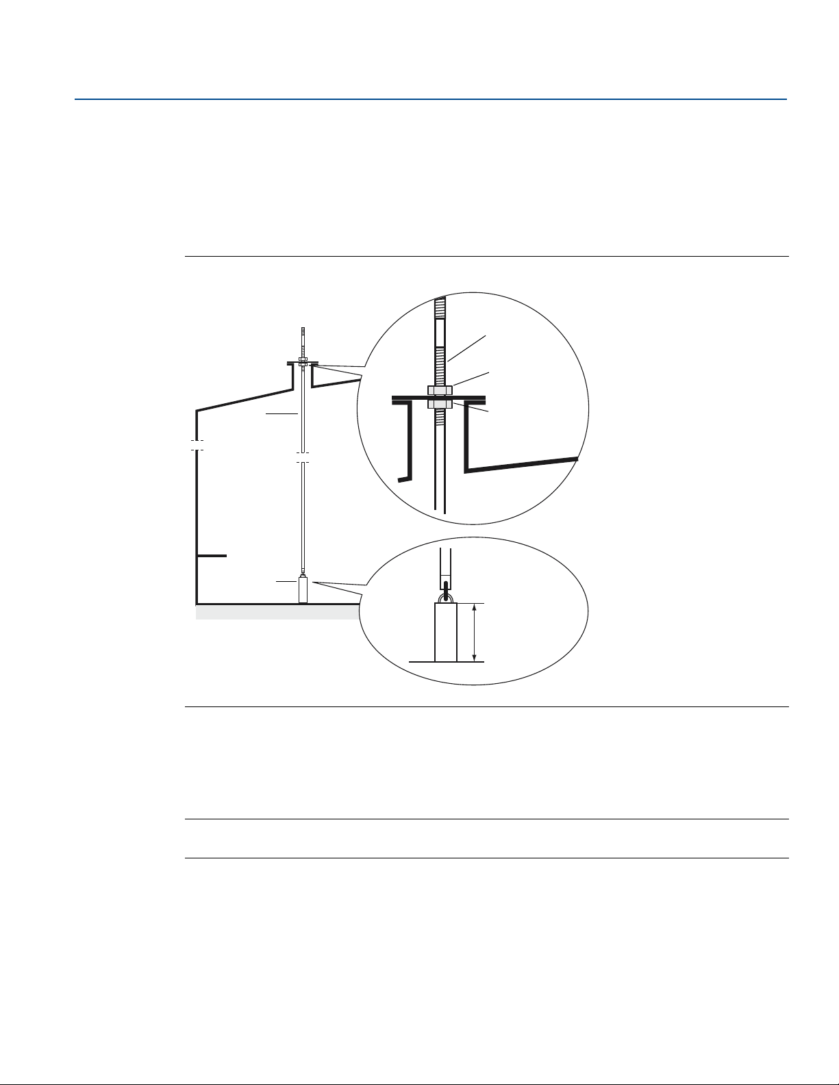
3.5 Installing a temperature sensor tube
Follow these steps to install the temperature sensor tube:
1. Mount the anchor weight on the tube.
2. Mount the tube so that the threads at the top of the tube fits the nozzle flange as illustrated in
Figure 3-5:
Figure 3-5. Adjusting the temperature sensor tube
Sensor Installation
May 2020
Sensor Installation
3. When the tube is placed on the nozzle, adjust the vertical position with the lock nuts. If a weight is
placed at the end of the tube, it should barely touch the tank bottom.
4. Install the Rosemount 2240S Multi-Input Temperature Transmitter, see “Mechanical installation” on
page 31.
Note
Ensure that the flexible protection tube is in a vertical position to obtain correct measurement data.
25
Page 38
Sensor Installation
A
B
G
H
I
J
C
D
E
F
May 2020
Reference Manual
00809-0100-2240, Rev EA
3.6 Rosemount 614 Cryogenic Spot Temperature Sensor
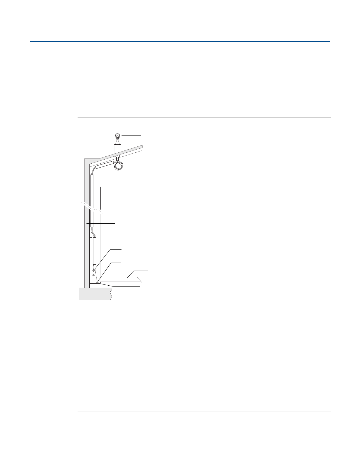
This section shows a couple of application examples that use Rosemount 2240S Temperature
Transmitters and Rosemount 614 Cryogenic Temperature Sensors in LNG full containment tanks. The
Rosemount 614 is suitable for leakage detection as well as skin temperature and cool-down monitoring
in LNG tanks.
3.6.1 Leakage detection on LNG full containment tank
Figure 3-6. Example of Leakage Detection Installation
26
A: Rosemount 2240S Multi-input Temperature Transmitter (mounted on cone connection)
B. Rosemount 614 Cryogenic Spot Temperature Sensor
Minimum bending radius=100 mm (3.9 in.)
C. Inner tank wall
D. Annular space
E. Sensor support
F. Concrete secondary container
G. Rosemount 614 leak sensor at corner protection
H. Rosemount 614 leak sensor for annular space
I. Inner tank bottom
J. Second tank bottom
Sensor Installation
Page 39
Reference Manual
A
B
C
D
00809-0100-2240, Rev EA
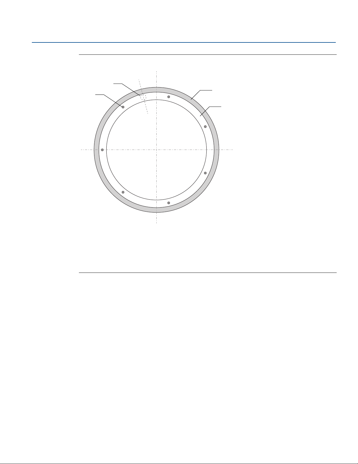
Figure 3-7. Typical Distribution of Temperature Sensor Elements
Sensor Installation
May 2020
A. Corner protection
B. Temperature sensor elements
C. Concrete secondary container
D. Annular space
Sensor Installation
27
Page 40
Sensor Installation
A
B
D
E
F
G
H
C
May 2020
Reference Manual
00809-0100-2240, Rev EA
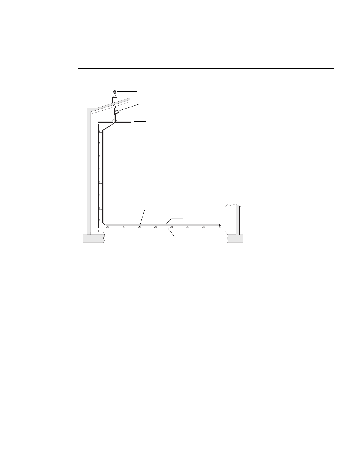
3.6.2 Skin temperature and cool-down monitoring on LNG tank
Figure 3-8. Example of Skin Temperature and Cool-down Monitoring Installation
28
A: Rosemount 2240S Multi-input Temperature Transmitter (mounted on cone connection)
B. Rosemount 614 Cryogenic Spot Temperature Sensors.
Minimum bending radius=100 mm (3.9 in.)
C. Suspend deck
D. Sensor support
E. Inner tank wall
F. Temperature sensor element
G. Sensor support for guiding sensor
H. Inner tank bottom
Sensor Installation
Page 41
Reference Manual
00809-0100-2240, Rev EA
Rosemount
™ 2240S Installation
May 2020
Section 4 Rosemount™ 2240S Installation
Safety messages . . . . . . . . . . . . . . . . . . . . . . . . . . . . . . . . . . . . . . . . . . . . . . . . . . . . . . . . . . . . . . . . . . page 29
Installation considerations . . . . . . . . . . . . . . . . . . . . . . . . . . . . . . . . . . . . . . . . . . . . . . . . . . . . . . . . . page 30
Mechanical installation . . . . . . . . . . . . . . . . . . . . . . . . . . . . . . . . . . . . . . . . . . . . . . . . . . . . . . . . . . . . page 31
Electrical installation . . . . . . . . . . . . . . . . . . . . . . . . . . . . . . . . . . . . . . . . . . . . . . . . . . . . . . . . . . . . . . page 37
4.1 Safety messages
Procedures and instructions in this section may require special precautions to ensure the safety of the
personnel performing the operations. Information that raises potential safety issues is indicated by a
warning symbol ( ). Please refer to the following safety messages before performing an operation
preceded by this symbol.
Failure to follow safe installation and servicing guidelines could result in death or serious injury.
Make sure only qualified personnel perform the installation.
Use the equipment only as specified in this manual. Failure to do so may impair the protection provided
by the equipment.
Do not perform any service other than those contained in this manual unless you are qualified.
Substitution of components may impair Intrinsic Safety.
To prevent ignition of flammable or combustible atmospheres, disconnect power before servicing.
Explosions could result in death or serious injury.
Verify that the operating environment of the transmitter is consistent with the appropriate hazardous
locations certifications.
Before connecting a hand held communicator in an explosive atmosphere, make sure the instruments
in the loop are installed in accordance with intrinsically safe or non-incendive field wiring practices.
Do not remove the gauge cover in explosive atmospheres when the circuit is alive.
High voltage that may be present on leads could cause electrical shock.
Avoid contact with leads and terminals.
Make sure the main power to the Rosemount 2240S is off and the lines to any other external power
sources are disconnected or not powered while wiring the gauge.
Rosemount
™ 2240S Installation
29
Page 42

Rosemount
™ 2240S Installation
May 2020
4.2 Installation considerations
The information in this section covers installation considerations for the Rosemount 2240S Multi-input
Temperature Transmitter in order to achieve a proper installation and optimum measurement
performance.
In order to reduce the required cabling, Rosemount Tank Gauging devices, including the Rosemount
2240S, are designed for daisy-chain connection of the Tankbus and shield grounding to other field
devices.
The Rosemount 2240S is designed for installation:
on top of the MST/WLS
on top of Rosemount 614 cone
remote on a pipe or wall
With remote mounting of the Rosemount 2240S, the nut and sleeve at the bottom of the 2240S can be
replaced by a M32 cable gland, see “Components” on page 8 and “Ordering information” on page 149.
When the Rosemount 2240S transmitter is installed in a hazardous area, ensure that the installation
requirements according to “Hazardous areas” on page 40
Reference Manual
00809-0100-2240, Rev EA
are complied with.
Ensure that the recommended cable glands/conduits are used.
Ensure that the Tankbus is correctly terminated, see “Termination” on page 41.
Ensure that grounding is performed according to national and local electrical codes, see “Grounding” on
page 38.
Do not install the Rosemount 2240S in non-intended applications, for example environments where it
may be exposed to extremely intense magnetic fields or extreme weather conditions.
Ensure that the Rosemount 2240S is installed such that it is not exposed to higher pressure and
temperature than specified in Appendix A: Specifications and Reference Data.
It is the responsibility of the user to ensure that the device meets the specific inside tank installation
requirements such as:
chemical compatibility of wetted materials
design/operation pressure and temperature
30
Rosemount
™ 2240S Installation
Page 43
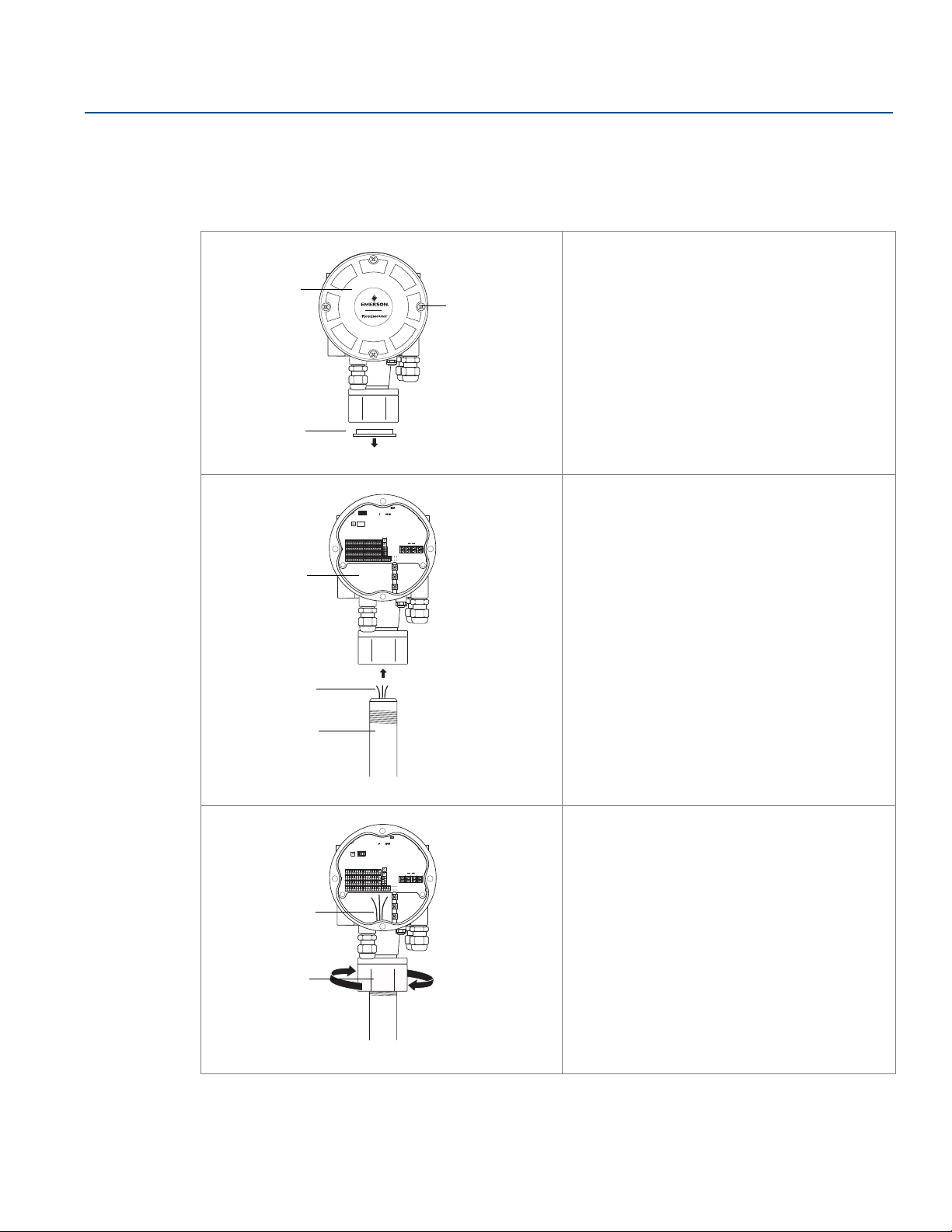
Reference Manual
Plug
Cover screws
(x4)
Cover
Sensor wires
Terminal
compartment
Sensor tube
Sensor wires
Nut
Rosemount
00809-0100-2240, Rev EA
4.3 Mechanical installation
4.3.1 Mounting on top of a temperature sensor/WLS
1. Ensure that the temperature and water
level sensors are properly installed as
described in Section 3: Sensor Installation.
2. Unscrew the four screws and remove the
cover.
3. Remove the plug that protects the cable
entry at the bottom of the 2240S
transmitter housing.
4. Attach the Rosemount 2240S transmitter
on top of the temperature sensor tube.
™ 2240S Installation
May 2020
5. Run the sensor wires into the terminal
compartment.
6. Tighten the nut on the transmitter by hand.
7. Proceed with electrical installation of
Tankbus, temperature elements, and water
level sensor. See “Electrical installation” on
page 37.
Rosemount
™ 2240S Installation
31
Page 44
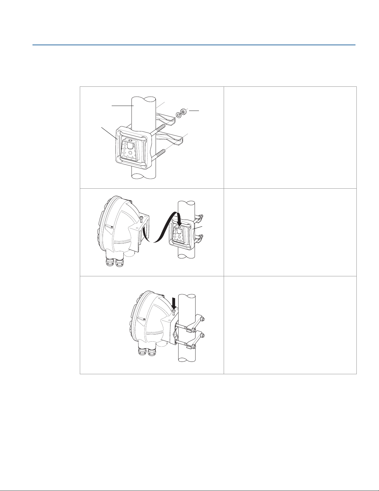
Rosemount
x4
Bracket
1 - 2 inches
Nuts
Bracket
Screw
™ 2240S Installation
May 2020
4.3.2 Mounting on a pipe
To mount Rosemount 2240S on a pipe, do the following:
Reference Manual
00809-0100-2240, Rev EA
1. Use the four nuts to fasten the bracket on
a vertical pipe. A suitable pipe size is 1 to 2
inches.
2. Attach the Rosemount 2240S transmitter
to the bracket.
32
3. Secure the transmitter with the screw on
top of the bracket.
4. Proceed with electrical installation of
Tankbus, temperature elements, and
water level sensor. See “Electrical
installation” on page 37.
Rosemount
™ 2240S Installation
Page 45
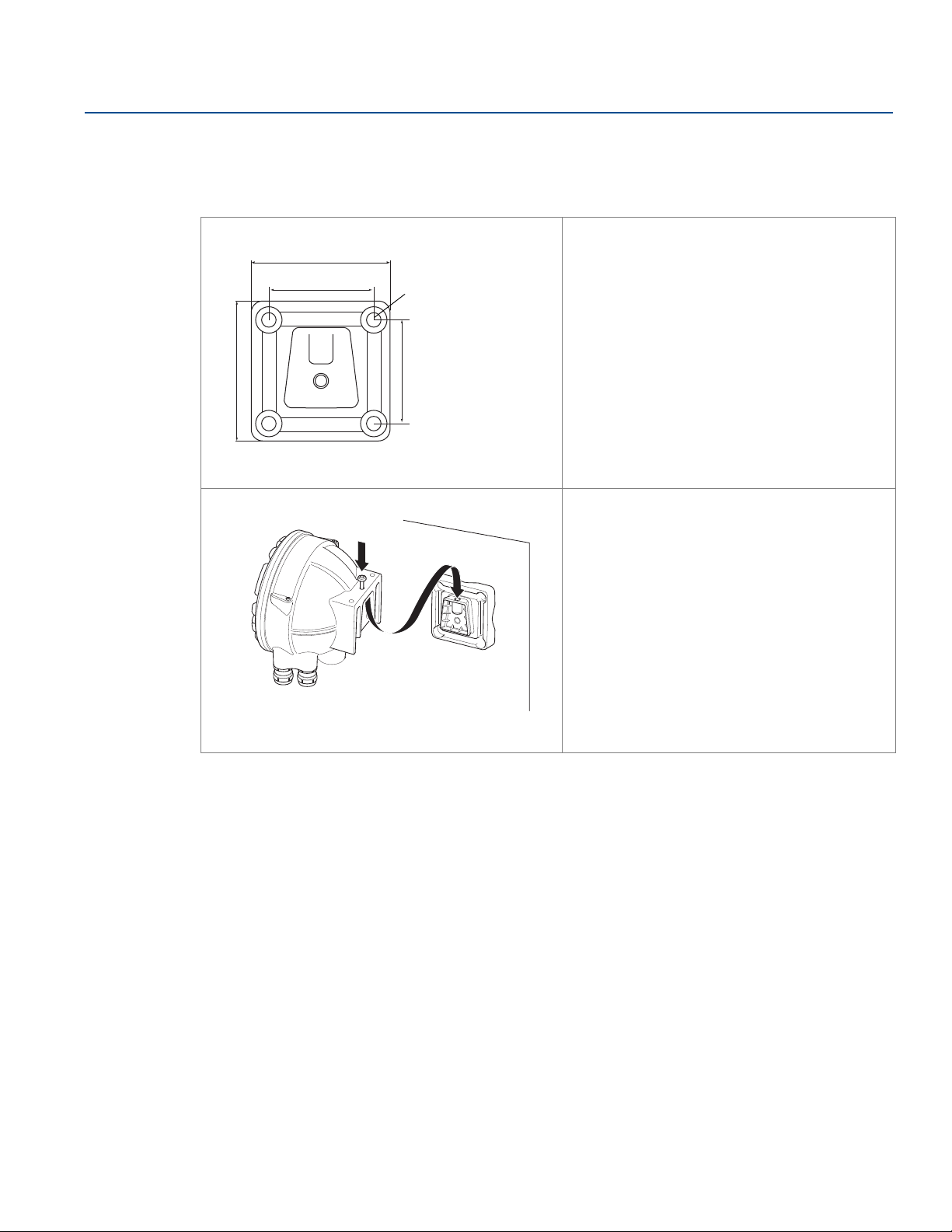
Reference Manual
70 mm (2.7 in.)
70 mm (2.7 in.)
Ø 9mm (0.35 in.)
94 mm (3.7 in.)
94 mm (3.7 in.)
Screw
00809-0100-2240, Rev EA
4.3.3 Wall mounting
To mount the Rosemount 2240S on a wall, do the following:
Rosemount
™ 2240S Installation
May 2020
1. Drill four 9 mm (0.35 in.) holes in the wall
to fit the hole pattern of the bracket.
2. Attach the bracket to the wall by using the
four M8 screws.
3. Attach the Rosemount 2240S transmitter
to the bracket.
4. Secure the transmitter with the screw on
top of the bracket.
5. Proceed with electrical installation of
Tankbus, temperature elements, and
water level sensor. See “Electrical
installation” on page 37.
Rosemount
™ 2240S Installation
33
Page 46
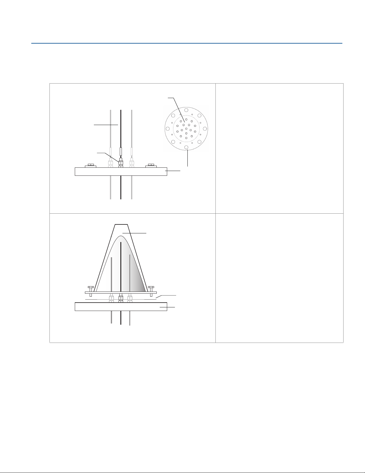
Rosemount
Sensor wires
Flange
Holes for sensor wires
Sensor fittings
Connection cone
Flange
Gasket
May 2020
™ 2240S Installation
Reference Manual
00809-0100-2240, Rev EA
4.3.4 Mounting the connection cone and Rosemount 614 sensor
1. Ensure that sensors are properly installed
in the tank.
2. Attach the Rosemount 614 temperature
sensors to the flange.
3. Torque the sensor fittings to the
recommended value of maximum 16 Nm.
See drawing D7000 005-451.
Note that sensor fittings should not be
opened once installed.
4. Attach the connection cone to the flange.
Gasket and screws are shipped with the
cone.
5. Pull the wires up through the opening at
the top of the connection cone.
34
Rosemount
™ 2240S Installation
Page 47
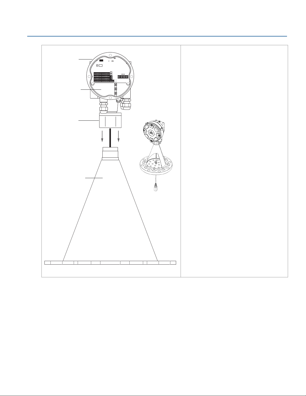
Reference Manual
Nut
Connection cone
Terminal
compartment
Rosemount 2240S
transmitter
00809-0100-2240, Rev EA
Rosemount
™ 2240S Installation
May 2020
6. Remove the cover from the Rosemount
2240S terminal compartment.
7. Place the transmitter on top of the
connection cone.
8. Tighten the nut by hand.
Rosemount
™ 2240S Installation
35
Page 48
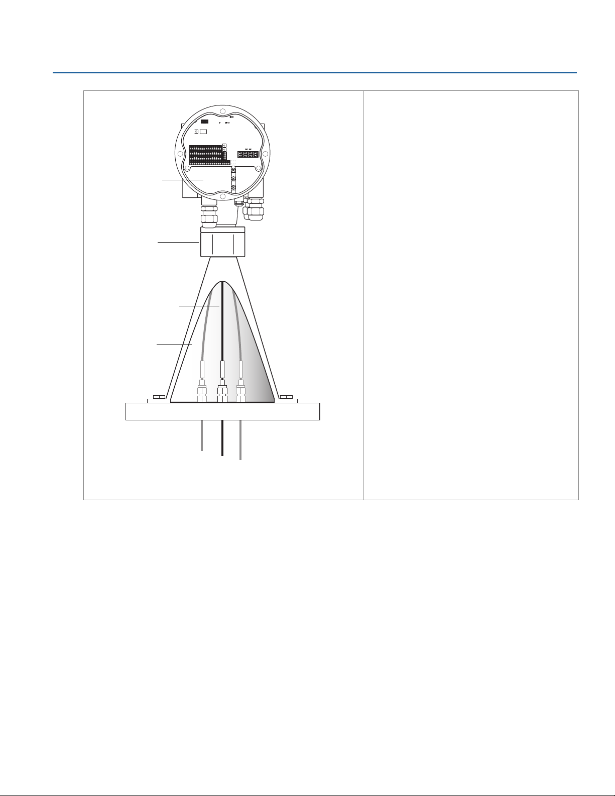
Rosemount
Nut
Connection cone
Terminal
compartment
Sensor wires
May 2020
™ 2240S Installation
Reference Manual
00809-0100-2240, Rev EA
9. Run the temperature sensor wires through
the sleeve at the bottom of the
transmitter housing into the terminal
compartment.
10.Wire the temperature sensors to the
Rosemount 2240S transmitter terminal
block. See “Temperature element and
Water Level Sensor wiring” on page 47.
36
Rosemount
™ 2240S Installation
Page 49
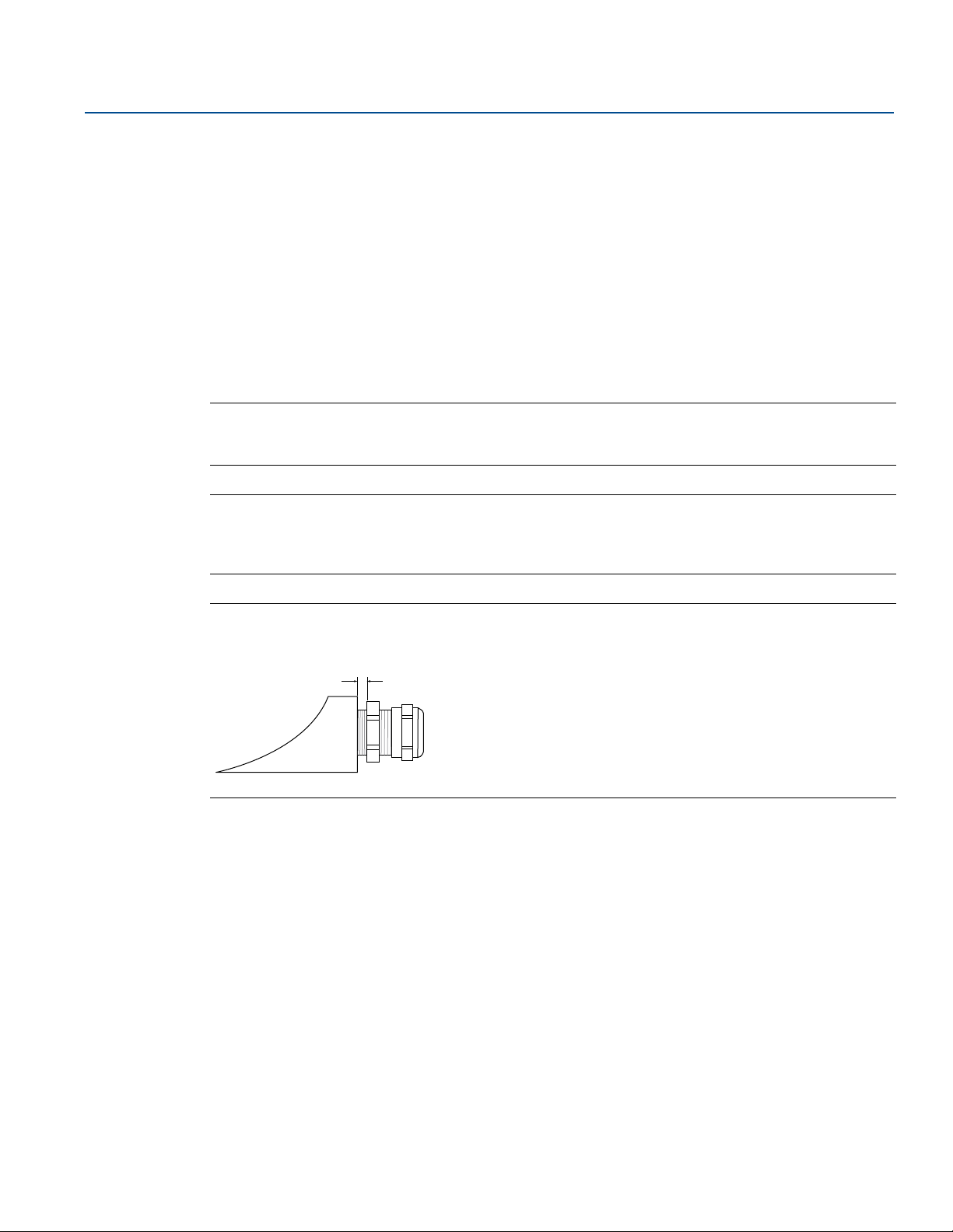
Reference Manual
Note that the NPT threaded gland leaves a
number of threads outside the housing
00809-0100-2240, Rev EA
4.4 Electrical installation
4.4.1 Cable/conduit entries
The electronics housing has three entries for ½ - 14 NPT glands. Optional M20×1.5, minifast and eurofast
adapters are also available.
For remote mounting, the nut and sleeve on the Rosemount 2240S can be replaced with a M32 gland for
connection of temperature sensors/WLS.
Connections must be made in accordance with local or plant electrical codes.
Make sure that unused ports are properly sealed to prevent moisture or other contamination from
entering the terminal block compartment of the electronics housing.
Note
Use the enclosed metal plugs to seal unused ports. The plastic plugs mounted at delivery are not
sufficient as seal!
Note
Thread sealing (PTFE) tape or paste on male threads of conduit is required to provide a water/dust tight
conduit seal and to meet the required degree of ingress protection as well as to enable future removal of
the plug/gland.
Rosemount
™ 2240S Installation
May 2020
Figure 4-1. Cable Entry with NPT Threaded Gland
Ensure that glands for the cable entries meet the following requirements:
IP class 66 and 67
material: metal (recommended)
4.4.2 Power requirements
The Rosemount 2240S temperature transmitter is powered over the Tankbus by the Rosemount 2410
Tank Hub. The Rosemount 2240S has a current consumption of 30 mA.
When installed in a F
OUNDATION fieldbus system, the Rosemount 2240S is powered by the FF segment.
Rosemount
™ 2240S Installation
37
Page 50
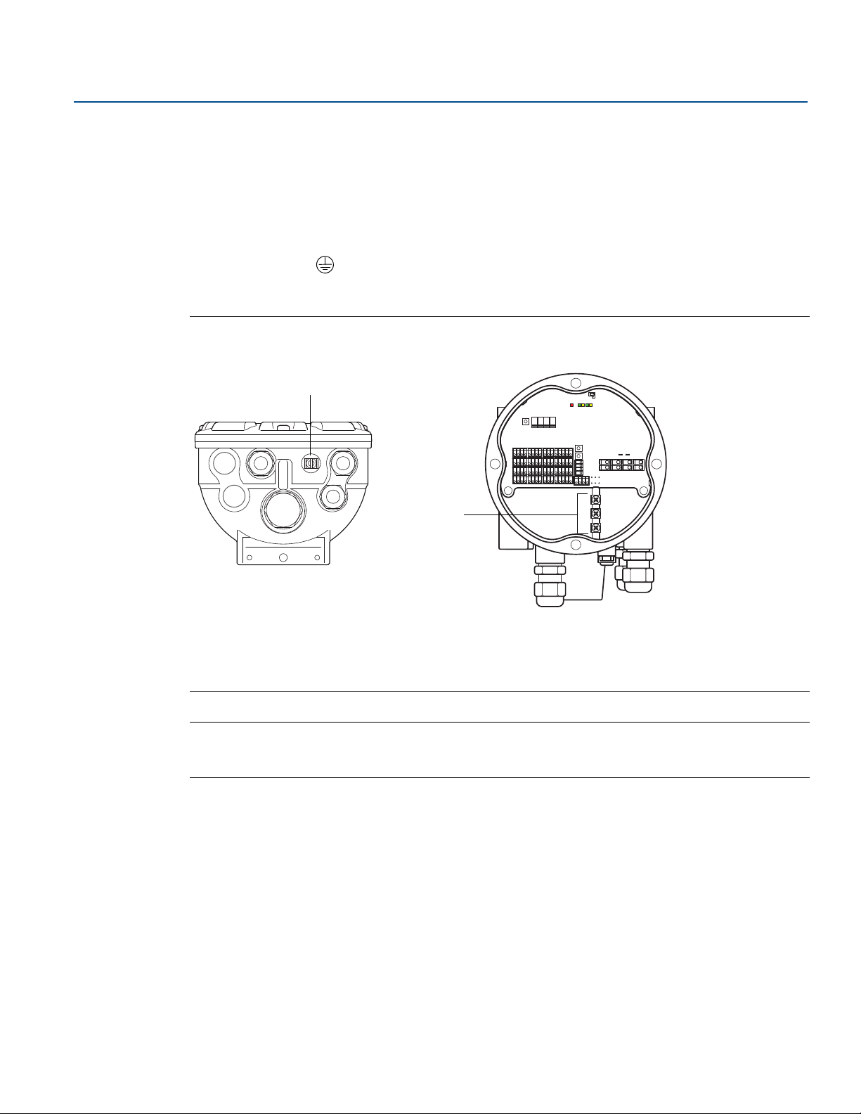
Rosemount
A
B
™ 2240S Installation
May 2020
4.4.3 Grounding
The housing should always be grounded in accordance with national and local electrical codes. Failure to
do so may impair the protection provided by the equipment. The most effective grounding method is
direct connection to ground with minimal impedance.
There is an external grounding screw located at the bottom of the housing and three internal grounding
screws located inside the housing, see Figure 4-2 on page 38. The internal ground screws are identified
by a ground symbol: .
Use the external ground terminal on the transmitter to ground the housing.
Figure 4-2. Grounding Terminals
Reference Manual
00809-0100-2240, Rev EA
38
A. External ground terminal
B. Internal ground terminals
Note
Grounding the transmitter using the threaded conduit connection may not provide a sufficient ground.
Make sure the connection provides a sufficiently low impedance.
Grounding - Tankbus
Signal wiring of the fieldbus segment (Tankbus) must not be grounded. Grounding one of the signal
wires may shut down the entire fieldbus segment.
Rosemount
™ 2240S Installation
Page 51

Reference Manual
00809-0100-2240, Rev EA
Shield wire ground
To protect the fieldbus segment (Tankbus) from noise, grounding techniques for shield wire usually
require a single grounding point to avoid creating a ground loop. The ground point is typically at the
power supply.
In the Rosemount Tank Gauging system, a ground point is located at the Rosemount 2410 Tank Hub
which acts as the power supply for devices on the Tankbus.
The Rosemount Tank Gauging devices are designed for “daisy-chain” connection of shield wiring in order
to enable a continuous shield throughout the Tankbus network.
The shield loop-through terminal in the Rosemount 2240S is not connected to ground in order to
provide electrical continuity to “daisy-chained” Tankbus cables.
4.4.4 Cable selection
Rosemount
™ 2240S Installation
May 2020
Use shielded twisted pair wiring for the Rosemount 2240S in order to comply with FISCO
(1)
requirements
and EMC regulations. The preferred cable is referred to as type “A” fieldbus cable. The cables must be
suitable for the supply voltage and approved for use in hazardous areas, where applicable. In the U.S.
explosion-proof conduits may be used in the vicinity of the vessel.
Use 22 AWG to 16 AWG (0.5 to1.5 mm²) in order to minimize the voltage drop to the transmitter.
The FISCO specification requires that cables comply with the following parameters:
Table 4-1. FISCO Cable Parameters
Parameter Value
Loop resistance 15 to 150 /km
Loop inductance 0.4 to 1 mH/km
Capacitance per unit length 45 to 200 nF/km
Maximum length of each spur cable 60 m in gas Groups IIC and IIB
Maximum length of each trunk cable
1 km in gas Group IIC and 1.9 km in
gas Group IIB
1, See IEC 61158-2 and IEC/TS 60079-27:2002.
Rosemount
™ 2240S Installation
39
Page 52

Rosemount
May 2020
™ 2240S Installation
4.4.5 Hazardous areas
When the Rosemount 2240S is installed in a hazardous area, national and local regulations and
specifications in applicable certificates must be observed. See Appendix B: Product Certifications.
Note
When the temperature transmitter is powered from a certified Ex [ib] or AEx [ib] FISCO Power Supply
with triplicated output voltage limitation meeting the requirements for two faults (“ia” voltage
limitation), e.g. a Rosemount 2410 Tank Hub via the Tankbus, the FISCO codings according to Control
Drawings 9240040-910 and 9240040-976, Note 8, apply, and the Rosemount 2240S can be connected
to RTDs or other sensors located in Zone 0.
However, Rosemount 2240S with ATEX and IECEx Certifications as well as Zone classification in USA and
Canada is also Ex-coded Ex ia or AEx ia (part of code) for both FISCO and Entity installations. In order to
maintain this coding the Rosemount 2240S must be powered from a Power Supply coded Ex [ia] or
AEx [ia]. Most general FISCO power supplies are, however, coded Ex [ib] for ATEX and IECEx and if the
Rosemount 2240S is powered from such a Power Supply, which has not triplicated output voltage
limitation, the Rosemount 2240S coding automatically becomes Ex ib.
This means that, in this case, neither the Rosemount 2240S itself nor any RTD or other sensors
connected to the RTD terminals or RS485/Modbus terminals of the Rosemount 2240S may be located in
Zone 0.
Reference Manual
00809-0100-2240, Rev EA
40
Rosemount
™ 2240S Installation
Page 53

Reference Manual
00809-0100-2240, Rev EA
4.4.6 The Tankbus
The Rosemount Tank Gauging system is easy to install and wire. Field devices can be “daisy-chained” thus
reducing the number of external junction boxes. Devices communicate with a Rosemount 2410 Tank
Hub via the intrinsically safe Tankbus that complies with the FISCO
Rosemount 2410 acts as power supply to the field devices on the Tankbus. A FISCO system enables more
field devices to be connected to the segment compared to conventional I.S. systems based on the entity
concept.
Termination
A terminator is needed at each end of a FOUNDATION fieldbus network. Generally, one terminator is placed
at the fieldbus power supply, and the other one at the last device in the fieldbus network.
Note
Ensure there are two terminators on the Tankbus, see Figure 4-3.
In a Rosemount Tank Gauging system the Rosemount 2410 Tank Hub acts as power supply. Since the tank
hub normally is the first device in the fieldbus segment, the built-in termination is enabled at factory.
Rosemount
(1)
FOUNDATION fieldbus standard. The
™ 2240S Installation
May 2020
Devices such as the standard version of the Rosemount 5900S Radar Level Gauge, the Rosemount 2230
Graphical Field Display, and the Rosemount 2240S Multi-input Temperature Transmitter also have
built-in terminators which can easily be enabled by inserting a jumper in the terminal block when
necessary.
If the Rosemount 2240S is not the last device in the fieldbus network, disconnect the termination
jumper. See Figure 4-6 on page 45.
Segment design
When designing a FISCO fieldbus segment a few requirements need to be considered. Cabling has to
comply with FISCO requirements as described in “Cable selection” on page 39. You will also have to
ensure that the total operating current of the connected field devices is within the output capability of
the Rosemount 2410 Tank Hub. The tank hub is able to deliver 250 mA. In a Smart Wireless System the
maximum current is 200 mA. Consequently, the number of field devices has to be considered so that the
total current consumption is less than the available current. See section “Power Budget” in the
Rosemount 2410 Reference Manual
Another requirement is to ensure that the input voltage at the field device terminals is at least 9 V.
Therefore, the voltage drop in the fieldbus cables has to be taken into account.
Distances are normally quite short between the Rosemount 2410 Tank Hub and field devices on the
tank. In many cases you can use existing cables as long as the FISCO requirements are fulfilled (see “Cable
selection” on page 39).
See the Rosemount 2410 Reference Manual
Tank Gauging system.
for more information.
for more information on segment design of a Rosemount
1, FISCO=Fieldbus Intrinsically Safe Concept
Rosemount
™ 2240S Installation
41
Page 54
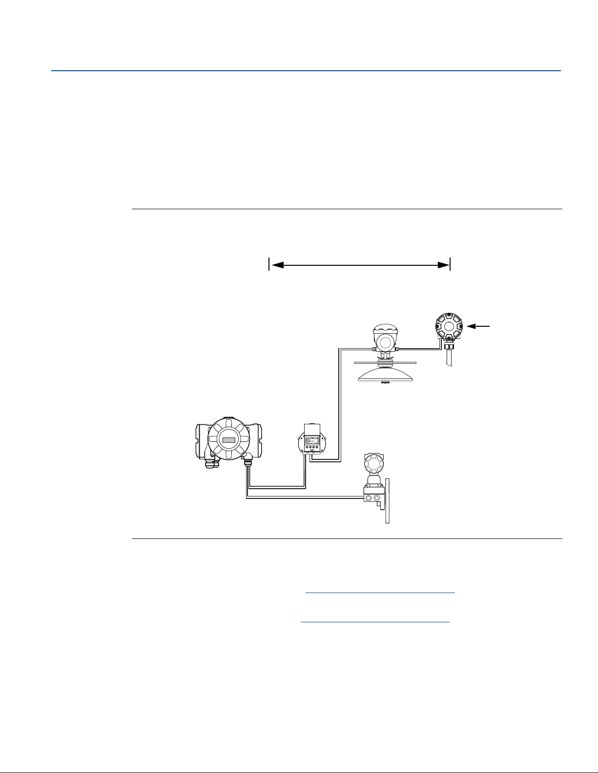
Rosemount
Rosemount
5900S Radar
Rosemount 2240S Multi-input
Temperature Transmitter
Built-in
terminator
enabled on the
last device
Rosemount
2230 Display
Rosemount 2410 Tank Hub with
intrinsically safe power supply,
integrated power conditioner, and
built-in terminator
Tankbus length up to 1000 meter depending on
number of devices and cable type
Tankbus
IS Analog Input
(Secondary bus)
Rosemount 3051S
Pressure Transmitter
Maximum number of HART Slave Devices
Passive current loop: 5
Active current loop: 3
™ 2240S Installation
May 2020
4.4.7 Typical installations
The example below (Figure 4-3) illustrates a system with daisy-chained field devices on a single tank.
Terminators are installed at both ends of the Tankbus segment as required in a system that complies with
the F
OUNDATION fieldbus standard. In this case terminators are enabled in the Rosemount 2410 Tank Hub
and a field device at the end of the network segment.
In addition to the field instruments on the Tankbus, Figure 4-3 illustrates how an instrument such as a
pressure transmitter can be connected to the intrinsically safe 4 -20 mA analog input of the Rosemount
2410 Tank Hub.
Figure 4-3. Example of a Tankbus Connection for a Single Tank
Reference Manual
00809-0100-2240, Rev EA
42
The maximum distance between the Rosemount 2410 Tank Hub and the field devices on the tank
depends on the number of devices connected to the Tankbus and the quality of cables.
See chapter “Electrical Installation” in the Rosemount 2410 Reference Manual
about cable selection, power budget, and the Tankbus.
See chapter “Typical Installations” in the Rosemount 2410 Reference Manual
to install systems that include the Rosemount 2410 Tank Hub.
for more information
for more examples of how
Rosemount
™ 2240S Installation
Page 55
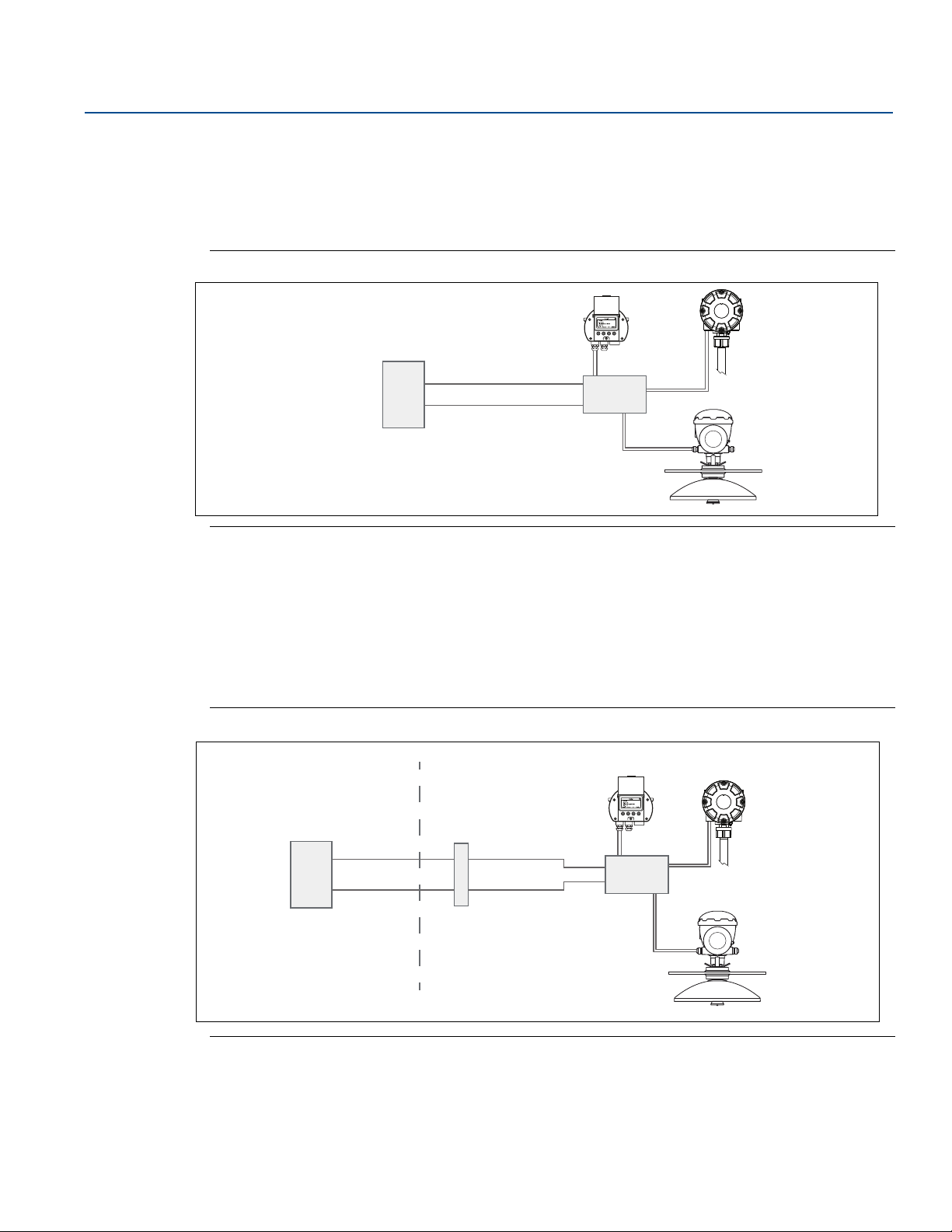
Reference Manual
Rosemount 5900S
Radar Level Gauge
Rosemount 2240S
Temperature
Rosemount 2230
FISCO/Entity compliant
FM USA, FM Canada:
AIS Class I, Division 1
ATEX and IECEx:
Ex [ia], or Ex [ib] (FISCO)
Ex [ia] (Entity)
Segment
Coupler
I.S. Power Supply
Trunk
Barrier
IS Trunk
SAFE AREA HAZARDOUS AREA
Segment
Coupler
Non-I.S. Power Supply
FISCO/Entity compliant
FM USA, FM Canada:
AIS Class I, Division 1
ATEX and IECEx:
Ex [ia], or Ex [ib] (FISCO)
Ex [ia] (Entity)
Rosemount 5900S
Radar Level Gauge
Rosemount 2240S
Temperature
Rosemount 2230
Rosemount
00809-0100-2240, Rev EA
4.4.8 Rosemount™ 2240S in FOUNDATION Fieldbus system
The Rosemount 2240S supports the FOUNDATION fieldbus (FF) technology and lets you integrate a
Rosemount 2240S into an existing FF network. As long as the power supply meets certain requirements
(see Figure 4-4 and Figure 4-5) the 2240S
Figure 4-4. Example of an I.S. FOUNDATION fieldbus System with Rosemount Devices
(1)
will be able to operate as any other FF device.
™ 2240S Installation
May 2020
Ensure that the power supply is able to provide the total current needed for all the connected devices.
See “Power requirements” on page 37 for further information.
Ensure that the Rosemount 2240S and other devices connected to the F
OUNDATION fieldbus (FF) system
are compliant with the FISCO or Entity parameters of the power supply.
Ensure that the short circuit protection of the Segment Coupler
(2)
matches the current consumption of
the connected devices.
Figure 4-5. Example of a Non-I.S. FOUNDATION Fieldbus System with Rosemount Devices
1, See Appendix B: Product Certifications for Rosemount 2240S approval information
2, See the Rosemount 2410 Reference Manual (Document No. 300530EN) for more information on the Segment Coupler.
Rosemount
™ 2240S Installation
43
Page 56

Rosemount
May 2020
™ 2240S Installation
4.4.9 Tankbus wiring
To connect a Rosemount 2240S:
1. Ensure that the power supply is switched off.
2. Loosen the four screws and remove the cover from the terminal compartment.
3. Run the Tankbus wires through the appropriate cable glands or conduits.
4. Connect the Tankbus wires to the X2 and X3 terminals as shown in Figure 4-6 on page 45.
5. Connect the cable shield to the terminal marked X1.
6. In case the Rosemount 2240S is installed at the end of a Tankbus network, enable the termination by
using a jumper between terminals X3 and X4 as shown in Figure 4-6 on page 45.
7. Use metal plugs to seal unused ports.
8. In order to prevent water from entering the terminal compartment, ensure the cover sealing is placed
in the correct position.
9. The cover on the terminal compartment should be tightened to mechanical stop (metal to metal).
Make sure the cover is fully engaged to meet explosion-proof requirement and to prevent water from
entering the terminal compartment.
Reference Manual
00809-0100-2240, Rev EA
10.Tighten the conduit/cable glands. Note that adapters are required for M20 glands.
Note
Ensure that o-rings and seats are in good condition prior to mounting the cover in order to maintain the
specified level of ingress protection. The same requirements apply for cable inlets and outlets (or plugs).
It is recommended that the O-ring is replaced when the cover is opened. O-rings are available as spare
parts. Cables must be properly attached to the cable glands.
44
Rosemount
™ 2240S Installation
Page 57
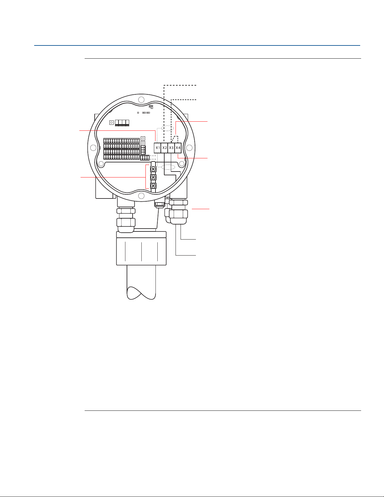
Reference Manual
Daisy-chain connection
to other field devices
(page 46)
C
D
E
F
A
I
H
B
G
00809-0100-2240, Rev EA
Figure 4-6. Rosemount 2240S Terminal Compartment
Rosemount
™ 2240S Installation
May 2020
A. X1: Cable Shield
B. Internal grounding terminals
C. X2: Tankbus (+) output
D. X3: Tankbus (-) output
E. Jumper to invoke built-in termination
F. X4: Tankbus terminator
G. Cable glands for Tankbus wires and temperature elements
H. X3: Tankbus (-) input
I. X2: Tankbus (+) input
Rosemount
™ 2240S Installation
45
Page 58
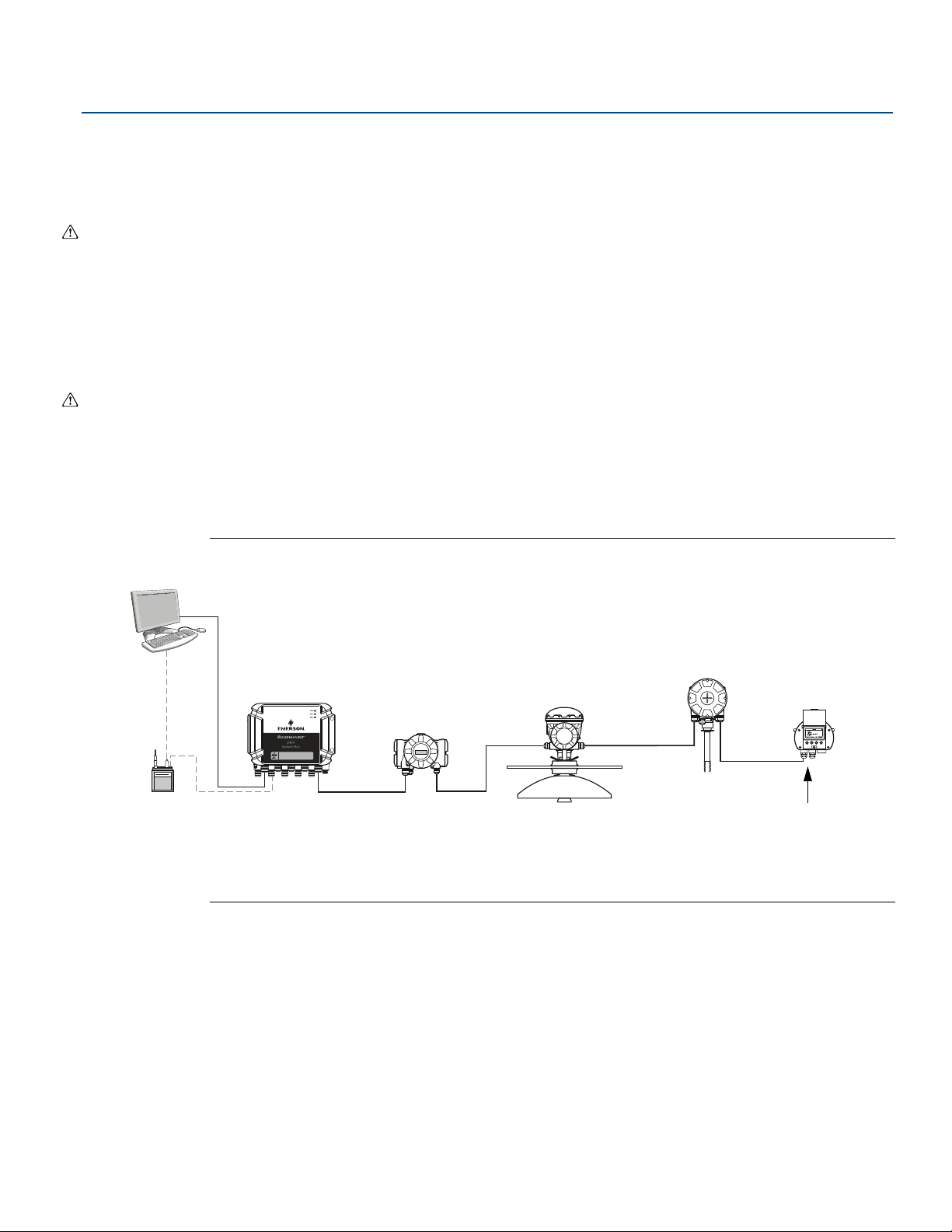
Rosemount
Tankbus
Rosemount TankMaster
Rosemount 2460 System Hub
Rosemount 2410 Tank Hub
Rosemount 2230 Display
Field Bus
Modem
TRL2 Modbus
Rosemount 5900S
Radar Level Gauge
Rosemount 2240S
Temperature Transmitter
Built-in
terminator
enabled on the
last device
Ethernet
™ 2240S Installation
May 2020
4.4.10 Daisy-chain connection
The Rosemount Tank Gauging system supports daisy-chain connection of devices to the Tankbus. To
daisy-chain the Rosemount 2240S to other devices do the following:
1. Make sure the power supply is switched off.
2. Loosen the four screws and remove the cover from the terminal compartment.
3. Disconnect the termination jumper from the X3 terminal, see Figure 4-6 on page 45.
4. Run the Tankbus cable into the Rosemount 2240S through an appropriate gland.
5. Connect the Tankbus wires to the X2 output and X3 output terminals as illustrated in Figure 4-6.
6. Connect the cable shield to the X1 terminal.
7. Attach and tighten the cover on the terminal compartment. Ensure the cover sealing is placed in the
correct position.
8. Tighten the conduit/cable glands. Note that adapters are required for M20 glands.
A typical wiring diagram with a Rosemount 2240S is illustrated in Figure 4-7. In the example below the
2240S is daisy-chained to a Rosemount 5900S Radar Level Gauge and a Rosemount 2230 Graphical Field
Display.
Reference Manual
00809-0100-2240, Rev EA
Figure 4-7. Rosemount 2240S Wiring Diagram
Ensure that there are only two terminators enabled on the Tankbus. In the example above, one
terminator is enabled in the Rosemount 2410 Tank Hub. The second terminator is enabled in the
terminal compartment of the Rosemount 2230 Display since this is the last device on the Tankbus
segment. Incorrect terminations may cause malfunctioning communication on the Tankbus.
46
Rosemount
™ 2240S Installation
Page 59
Reference Manual
Rosemount
00809-0100-2240, Rev EA
4.4.11 Temperature element and Water Level Sensor wiring
The Rosemount 2240S is compatible with multiple element Resistance Temperature Detectors (RTDs). A
Rosemount 2240S can connect up to sixteen 3- or 4-wire temperature spot elements.
Three connection types are supported: 3-wire with common return, 3-wire individual spot, and 4-wire
individual spot. The Rosemount 2240S is also compatible with averaging sensor types. A maximum of 16
elements can be connected to a Rosemount 2240S transmitter.
The Rosemount 2240S is also equipped with a RS485/Modbus terminal for connection of a Water Level
Sensor.
Note
If an averaging temperature detector is connected to the Rosemount 2240S, a DIP switch must be set,
see “DIP Switches” on page 66 for more information.
When a Rosemount 2240S transmitter is mounted on top of a MST/WLS or a Rosemount 614 cone
connection, the sensor wires will enter the terminal compartment through the sleeve at the bottom of
the Rosemount 2240S housing.
In case a Rosemount 2240S is mounted on a pipe or a wall (see “Mechanical installation” on page 31), the
sleeve and nut can be replaced by an M32 cable gland, see Figure 2-2 on page 8.
™ 2240S Installation
May 2020
There are three wiring types that can be used for temperature elements connected to a
Rosemount 2240S. The number of elements that can be connected varies depending on the type of
temperature sensor that is used as illustrated in Table 4-2:
Table 4-2. Number of Temperature Elements for Various Temperature Sensors and Wiring Types
Multiple Spot
Temperature Sensor
Rosemount 565 1-16 elements 1-16 elements 1-16 elements
Rosemount 566 1-16 elements 1-16 elements 1-16 elements
Rosemount 765 1-16 elements 1-14 elements 1-10 elements
Rosemount 614 NA 1-16 elements 1-16 elements
See Rosemount Tank Gauging System Data Sheet
3-wire
common return
3-wire individual 4-wire individual
for more information on various Multiple Spot
Temperature Sensors.
Note
Temperature elements must be connected in the order 1, 2, 3 etc. without any gaps (e.g 10 elements
must be connected to channel 1-10).
Note
Use terminals “b”, “c”, and “d” for 3-wire connections.
Rosemount
™ 2240S Installation
47
Page 60
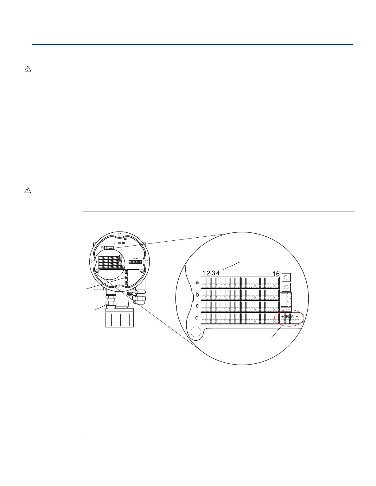
Rosemount
A
C
B
D
E
F
May 2020
™ 2240S Installation
Reference Manual
00809-0100-2240, Rev EA
To connect the sensor wires for a temperature detector to a Rosemount 2240S do the following:
1. Make sure the power supply is switched off.
2. Loosen the four screws and remove the cover from the terminal compartment.
3. Run the wires for temperature elements and water level sensor through the sleeve at the bottom of
the transmitter housing, see Figure 4-8.
If the 2240S transmitter is mounted on a wall or pipe (remote mounting), run the sensor wires
through the appropriate cable gland/conduit entry, see Figure 2-2 on page 8.
4. Connect the temperature sensor wires to the terminals marked “1” to “16” and “a”, “b”, “c”, and
“d”. Refer to Figure 4-9, Figure 4-10, and Figure 4-11 depending on the sensor type and
measurement method that is used.
5. Connect the red, green, white, and black water level sensor wires to the RS485/Modbus terminal as
shown in Figure 4-8.
6. Connect the shield on the water level sensor cable to one of the ground terminals.
7. Make sure the cover sealing is placed in the correct position.
8. Attach the cover on the terminal compartment and tighten the four screws.
9. Tighten the cable glands.
Figure 4-8. Terminal for Connection of Temperature Elements
A.Internal grounding terminals
B. Cable entries
C. Cable entry for integrated MST/WLS sensor
D. RTD channel numbers ( 1 .. 16)
E. RS485/Modbus terminal
F. Wire color: Red (+), Green (B), White (A), Black (-)
48
Rosemount
™ 2240S Installation
Page 61
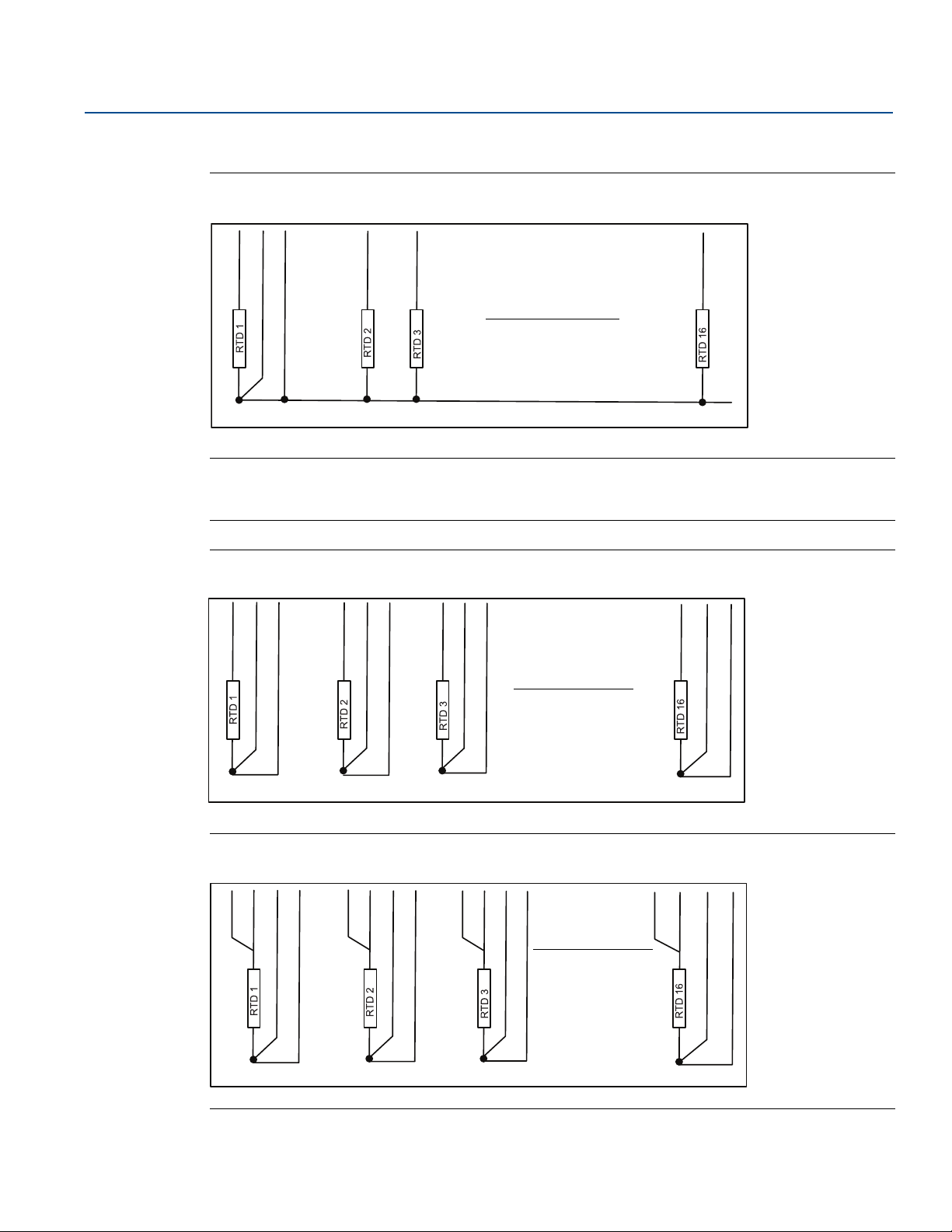
Reference Manual
Up to 16 channels
Common return
d1c1b1 b2 b16b3
T1 T2 T3 T16
Up to 16 channels
b1 c1 c2b2d1 d2 b3 d3c3 b16 d16c16
Individual return
T1 T2 T3 T16
Up to 16 channels
a1 b1 c1 d1 c2a2 b2 d2 a3 b3 a16c3 b16 c16 d16d3
Individual return
T1 T2 T3 T16
00809-0100-2240, Rev EA
The following wiring methods are supported:
Figure 4-9. 3-wire with Common Return
Note
Black wires (common/individual return) must always be connected to the c- and d- terminals on
left-hand side of the terminal block.
Rosemount
™ 2240S Installation
May 2020
Figure 4-10. 3-wire Individual Spot
Figure 4-11. 4-wire individual Spot
Rosemount
™ 2240S Installation
49
Page 62

Rosemount
May 2020
™ 2240S Installation
Cable color coding
Table 4-3. Cable Colors for the Rosemount 565/566/765 Temperature Sensors
Reference Manual
00809-0100-2240, Rev EA
Temperature
Element
T1 Brown
T2 Red
T3 Orange
T4 Yellow
T5 Green
T6 Blue
T7 Violet
T8 Grey
T9 White
T10 Pink
T11 Brown/Black
T12 Red/Black
T13 Orange/Black
T14 Yellow/Black
T15 Green/Black
T16 Blue/Black
Color
50
Rosemount
™ 2240S Installation
Page 63
Reference Manual
00809-0100-2240, Rev EA
Configuration/Operation
Section 5 Configuration/Operation
Safety messages . . . . . . . . . . . . . . . . . . . . . . . . . . . . . . . . . . . . . . . . . . . . . . . . . . . . . . . . . . . . . . . . . . page 51
Introduction . . . . . . . . . . . . . . . . . . . . . . . . . . . . . . . . . . . . . . . . . . . . . . . . . . . . . . . . . . . . . . . . . . . . . page 52
Basic configuration . . . . . . . . . . . . . . . . . . . . . . . . . . . . . . . . . . . . . . . . . . . . . . . . . . . . . . . . . . . . . . . page 54
LED signals . . . . . . . . . . . . . . . . . . . . . . . . . . . . . . . . . . . . . . . . . . . . . . . . . . . . . . . . . . . . . . . . . . . . . . . page 64
Switches and reset buttons . . . . . . . . . . . . . . . . . . . . . . . . . . . . . . . . . . . . . . . . . . . . . . . . . . . . . . . . page 66
Configuration using TankMaster WinSetup . . . . . . . . . . . . . . . . . . . . . . . . . . . . . . . . . . . . . . . . . . page 69
F
OUNDATION
General block information . . . . . . . . . . . . . . . . . . . . . . . . . . . . . . . . . . . . . . . . . . . . . . . . . . . . . . . . . page 75
Analog Input block . . . . . . . . . . . . . . . . . . . . . . . . . . . . . . . . . . . . . . . . . . . . . . . . . . . . . . . . . . . . . . . . page 77
Analog Output block . . . . . . . . . . . . . . . . . . . . . . . . . . . . . . . . . . . . . . . . . . . . . . . . . . . . . . . . . . . . . . page 83
Multiple Analog Input blocks . . . . . . . . . . . . . . . . . . . . . . . . . . . . . . . . . . . . . . . . . . . . . . . . . . . . . . . page 85
Resource block . . . . . . . . . . . . . . . . . . . . . . . . . . . . . . . . . . . . . . . . . . . . . . . . . . . . . . . . . . . . . . . . . . . page 86
Configuration using a field communicator . . . . . . . . . . . . . . . . . . . . . . . . . . . . . . . . . . . . . . . . . . . page 93
Configuration using AMS Device Manager . . . . . . . . . . . . . . . . . . . . . . . . . . . . . . . . . . . . . . . . . . . page 94
Alert setup . . . . . . . . . . . . . . . . . . . . . . . . . . . . . . . . . . . . . . . . . . . . . . . . . . . . . . . . . . . . . . . . . . . . . . . page 106
™ FIELDBUS OVERVIEW . . . . . . . . . . . . . . . . . . . . . . . . . . . . . . . . . . . . . . . . . . . . . . . . . . . . . . . . . . . . . . . . . . . . . . . . . . . . . . . . . . . . . . . PAGE 70
May 2020
5.1 Safety messages
Procedures and instructions in this section may require special precautions to ensure the safety of the
personnel performing the operations. Information that raises potential safety issues is indicated by a
warning symbol ( ). Please refer to the following safety messages before performing an operation
preceded by this symbol.
Failure to follow safe installation and servicing guidelines could result in death or
serious injury:
Make sure only qualified personnel perform the installation.
Use the equipment only as specified in this manual. Failure to do so may impair the
protection provided by the equipment.
Do not perform any service other than those contained in this manual unless you are
qualified.
Explosions could result in death or serious injury:
Verify that the operating environment of the transmitter is consistent with the appropriate
hazardous locations certifications.
Before connecting a FF communicator in an explosive atmosphere, make sure the
instruments in the loop are installed in accordance with intrinsically safe or non-incendive
field wiring practices.
Do not remove the gauge cover in explosive atmospheres when the circuit is alive.
Configuration/Operation
51
Page 64

Configuration/Operation
May 2020
5.2 Introduction
This chapter provides information about configuration of the Rosemount™ 2240S Multi-input
Temperature Transmitter regardless of the configuration tool used. However, you will find frequent
references to TankMaster WinSetup, which is the recommended configuration tool.
It is important that configuration is properly prepared by listing the appropriate Modbus addresses,
device tags, and tank tags.
5.2.1 Configuration procedure
Basically, a Rosemount 2240S can be installed and configured by one of the following methods:
As part of the installation of a Rosemount 2410 Tank Hub. This is the standard procedure when a new
system is installed, see the Rosemount Tank Gauging System Configuration Manual
As a separate device, connected to the Tankbus of a Rosemount 2410 in an existing Rosemount Tank
Gauging system. The device is configured with a suitable tool, such as TankMaster WinSetup.
As a separate device in a FOUNDATION
configuration.
5.2.2 Parameters
Reference Manual
00809-0100-2240, Rev EA
.
™
fieldbus system. AMS Device Manager may be used for
Temperature elements
The basic configuration includes parameters for a standard configuration which is sufficient in most
cases. The following parameters are configured:
number of temperature elements
temperature element type (Spot or Average)
position in tank
temperature elements excluded from average calculation
minimum distance between element and product surface for element to be included in average
temperature calculation (insert distance)
Water Level Sensor
Configuration of the water level sensor includes:
level offset (difference between tank zero level and water zero level)
probe length
upper and lower dead zone
52
Configuration/Operation
Page 65

Reference Manual
00809-0100-2240, Rev EA
5.2.3 Configuration tools
Different tools are available for configuration of a Rosemount 2240S:
Rosemount TankMaster Winsetup
Field Communicator
AMS Device Manager for FOUNDATION
FOUNDATION fieldbus hosts supporting DD4
TankMaster is an Emerson Automation Solutions/Rosemount Tank Gauging inventory management
software package for installation and configuration of level gauging equipment.
The WinSetup package provides you with powerful and easy-to-use tools for installation and
configuration, see the Rosemount Tank Gauging System Configuration Manual
For DeltaV users, the DD can be found at www.easydeltav.com. For other hosts that use Device
Descriptions (DD) and DD Methods for device configuration, the latest DD versions can be found on
F
OUNDATION’S website at www.fieldbus.org.
™
fieldbus systems
Configuration/Operation
May 2020
.
Configuration/Operation
53
Page 66
Configuration/Operation
May 2020
5.3 Basic configuration
Temperature elements and a Water Level Sensor can be connected to the Rosemount 2240S Multi-input
Temperature Transmitter.
5.3.1 Temperature elements
The Rosemount 2240S Multi-input Temperature Transmitter supports the configuration options listed in
Table 5-1 for connected temperature elements. These options can be configured in TankMaster
WinSetup via the 22XX ATD window (the Average Temperature Calculation and 2240 MTT Temperature
Sensor tabs). For F
Table 5-1. Rosemount 2240S Temperature Element Configuration
Settings Description
OUNDATION fieldbus systems the AMS Device Manager can be used.
Reference Manual
00809-0100-2240, Rev EA
Number of sensor temperature
elements
Sensor type Spot or average sensor types are supported.
Temperature sensor element
position in tank
Exclude spot sensor element
from tank average temperature
calculation
Insert distance
Default Sensor Configuration
Maximum 16 temperature elements
Specify the position of each temperature element in the tank, see
“Temperature sensor element positions” on page 55.
You can exclude certain spot elements from the average temperature
calculation, see “Tank average temperature calculation” on page 55.
Minimum distance between element and surface for element to be
included in average calculation, see “Insert distance” on page 56.
This option controls whether the temperature sensor is automatically
configured based on the “Averaging RTD” DIP switch setting, or if manual
configuration is required. Default configuration means that the sensor is
configured according to a specific default setting.
See “DIP Switches” on page 66 for more information.
(1)
.
• Auto
• PT100 (spot)
• CU90 (average)
Conversion method
• CU90US
• User-defined (see “Conversion methods” on page 69):
- linearization table
- formula
- individual formula
54
Temperature range Measurement range of the temperature elements
Type of sensor wiring:
Sensor wiring (Connection)
• 3 wire spot or average with common return
• 3 wire independent spot
• 4 wire independent spot
1. The Rosemount 2460 System Hub supports 16 elements and the Rosemount 2160 Field Communication Unit supports a maximum of 14
temperature spot elements. However, Average Temperature will be correctly calculated by a Rosemount 2410 Tank Hub connected to a
Rosemount 2240S with 16 temperature elements regardless if the tank hub is connected to a Rosemount 2460 or a Rosemount 2160.
Configuration/Operation
Page 67
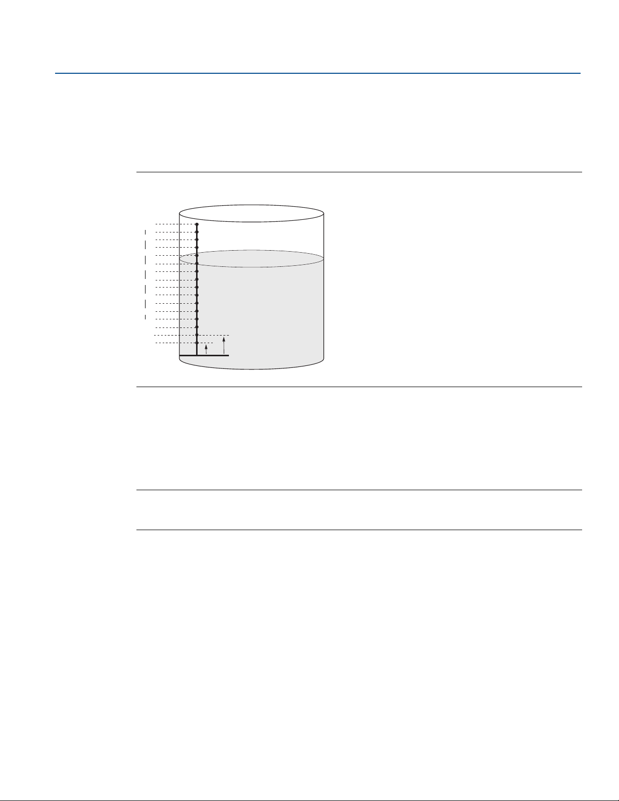
Reference Manual
16
2
3
1
Zero Level
00809-0100-2240, Rev EA
Temperature sensor element positions
The temperature elements are numbered from the bottom of the tank and upwards. Enter the position
of each element, measured as the distance from the Zero Level (Dipping Datum Plate) to the
temperature element. If you use average temperature elements, enter the position of the terminating
level of each sensor element.
Figure 5-1. Temperature sensor element positions
Configuration/Operation
May 2020
Tank average temperature calculation
You can exclude certain spot elements from the average temperature calculation. This may be useful if,
for example, the temperature close to the surface or close to the bottom of the tank deviates
significantly from the temperature in the rest of the tank. This may also be accomplished by setting an
appropriate value for the Insert Distance parameter, see “Insert distance” on page 56.
Note
A faulty temperature sensor will affect the temperature calculation. For more information see “Ground
fault detection” on page 115.
Configuration/Operation
55
Page 68
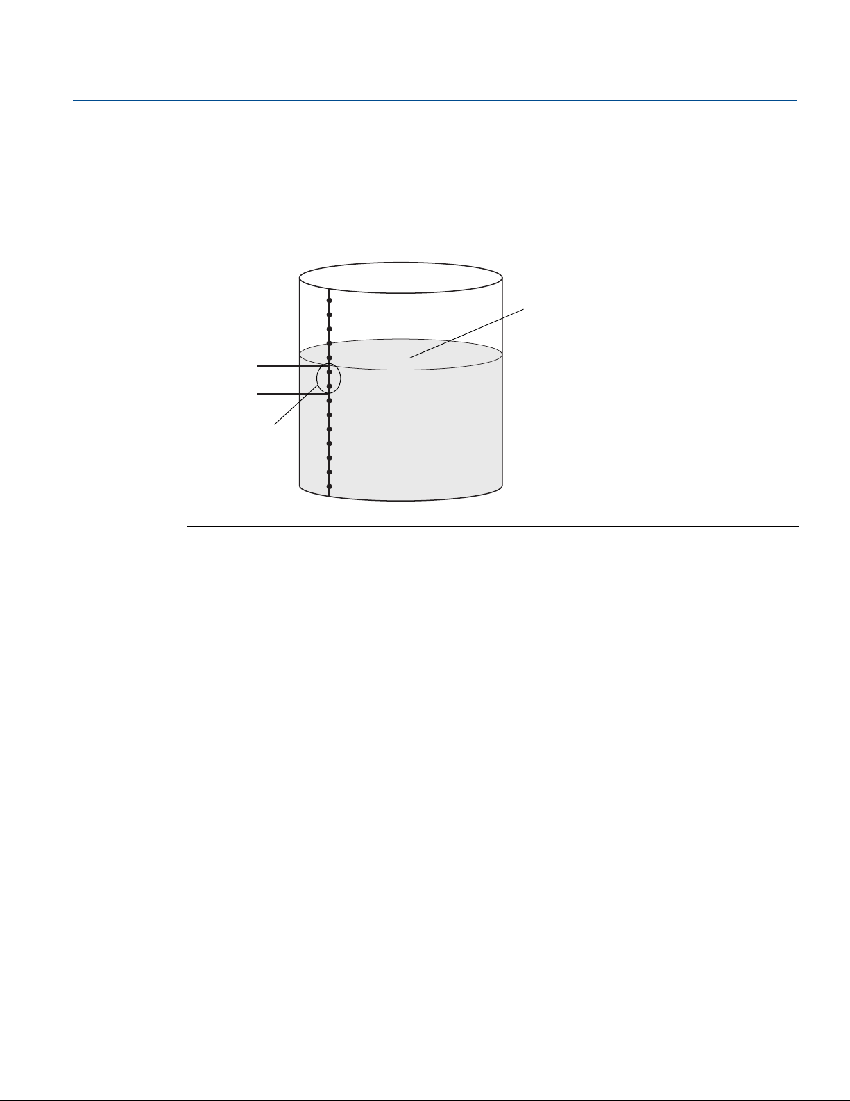
Configuration/Operation
Insert Distance
These sensors are not
included in the average
temperature
calculation
Product surface
May 2020
Insert distance
You can specify a minimum distance between the product surface and the first temperature spot
element to be included in the average temperature calculation. If the temperature spot element is within
or above the Insert Distance, the element will be excluded from the calculation.
Figure 5-2. Insert distance
Reference Manual
00809-0100-2240, Rev EA
This function may be useful if the temperature of the atmosphere above the product surface
significantly deviates from the temperature of the product itself, resulting in large temperature
gradients close to the product surface. By specifying an Insert Distance, temperature elements within
this region can be excluded from average temperature calculations.
The Insert Distance function can also be used to compensate for inaccuracies in the measured
temperature element positions, in order to make sure that elements above the product surface are not
included in the average temperature calculation. If, for example, temperature element positions are
measured with an accuracy of 10 mm, setting the minimum distance to at least 10 mm will guarantee
that sensors above the surface are not included in the average temperature calculations.
56
Configuration/Operation
Page 69
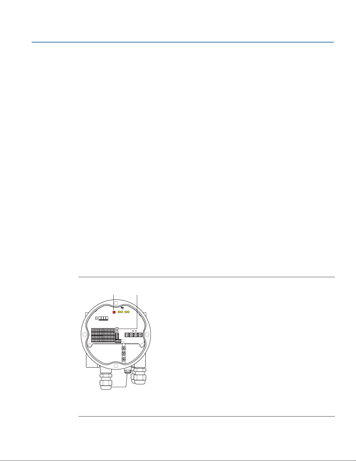
Reference Manual
AB
00809-0100-2240, Rev EA
5.3.2 Water Level Sensor calibration
The Water Level Sensor (WLS) measures the free water level below an oil surface. The WLS can be
combined with Multiple Spot Temperature sensors.
The WLS is factory calibrated for air. The factory calibration values are stored in a separate write
protected Holding Register area.
The following parameters are stored in the factory calibration:
Full = The measured capacitance value when the probe is completely covered with water
Empty = The measured capacitance value when the probe is completely covered by the reference
product
In case the dielectric constant of the product differs from factory calibration you will need to perform a
new empty calibration. In this case empty means that there is no water, i.e. the sensor is fully immersed
in oil.
Calibration procedure
1. Lift the Water Level Sensor from the bottom of the tank and ensure the sensor is covered by the
product (oil) only.
Configuration/Operation
May 2020
2. Wait five minutes.
3. Press the WLS Calibration button (A) on the Rosemount 2240S transmitter for at least two seconds
to start calibration (see Figure 5-3). Calibration is indicated with a steady LED light for about 10
seconds, then it is turned off.
4. When calibration is finished the status LED lights up with a steady light for about ten seconds. In case
of a calibration error, the LED blinks at a high frequency for 10 seconds, see Figure 5-4.
5. Wait for the Status LED (B) to turn from a steady light to normal LED status (blinking with 2 seconds
interval).
6. Once the calibration process is completed, anchor the Water Level Sensor to the bottom of the tank.
Figure 5-3. ZERO button and LED status signal
Configuration/Operation
A. WLS Calibration
B. LED status signal
57
Page 70
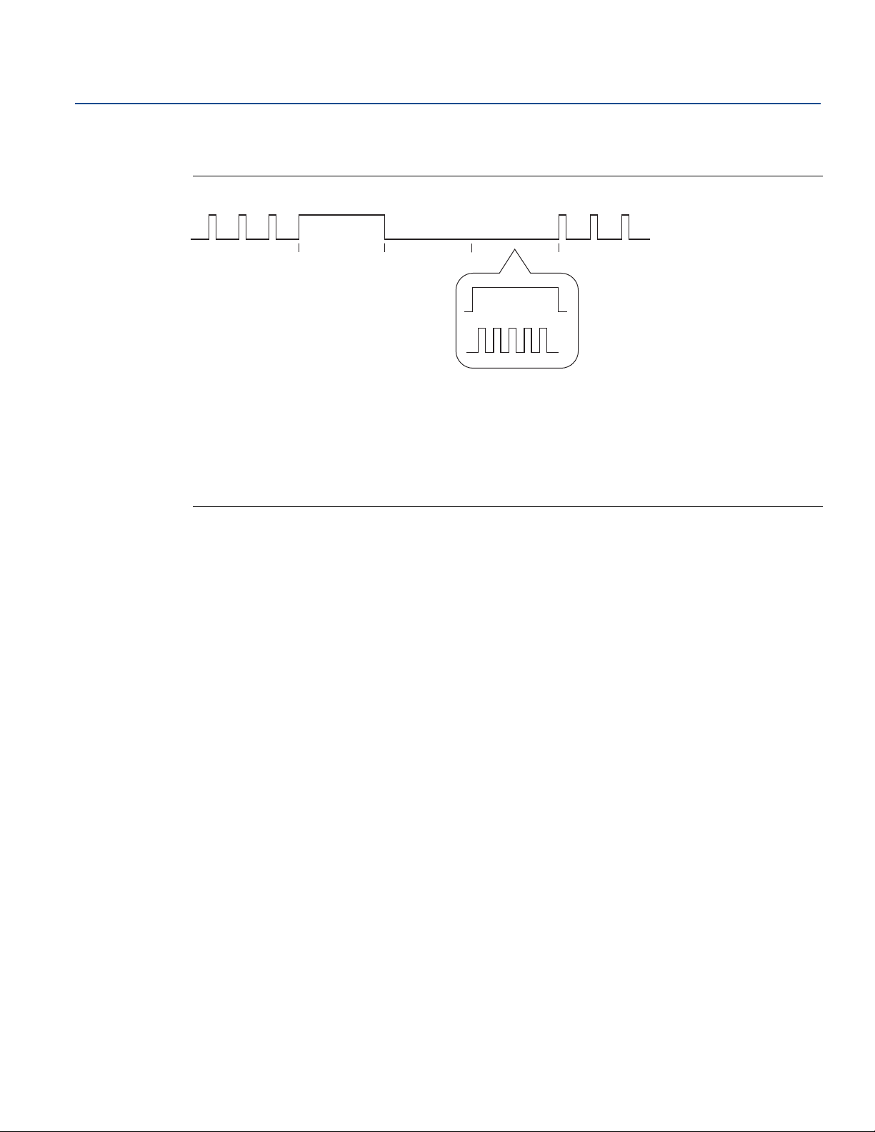
Configuration/Operation
ABC A
D
E
May 2020
The different phases of the calibration process are indicated by the LED inside the Rosemount 2240S
housing as shown in Figure 5-4.
Figure 5-4. Calibration status indicated by LED
A. Normal
B. Calibration starts (10 s)
C. Calibration ongoing (10 s)
D. Calibration OK (10 s)
E. Calibration FAILED (10 s)
Reference Manual
00809-0100-2240, Rev EA
58
Configuration/Operation
Page 71
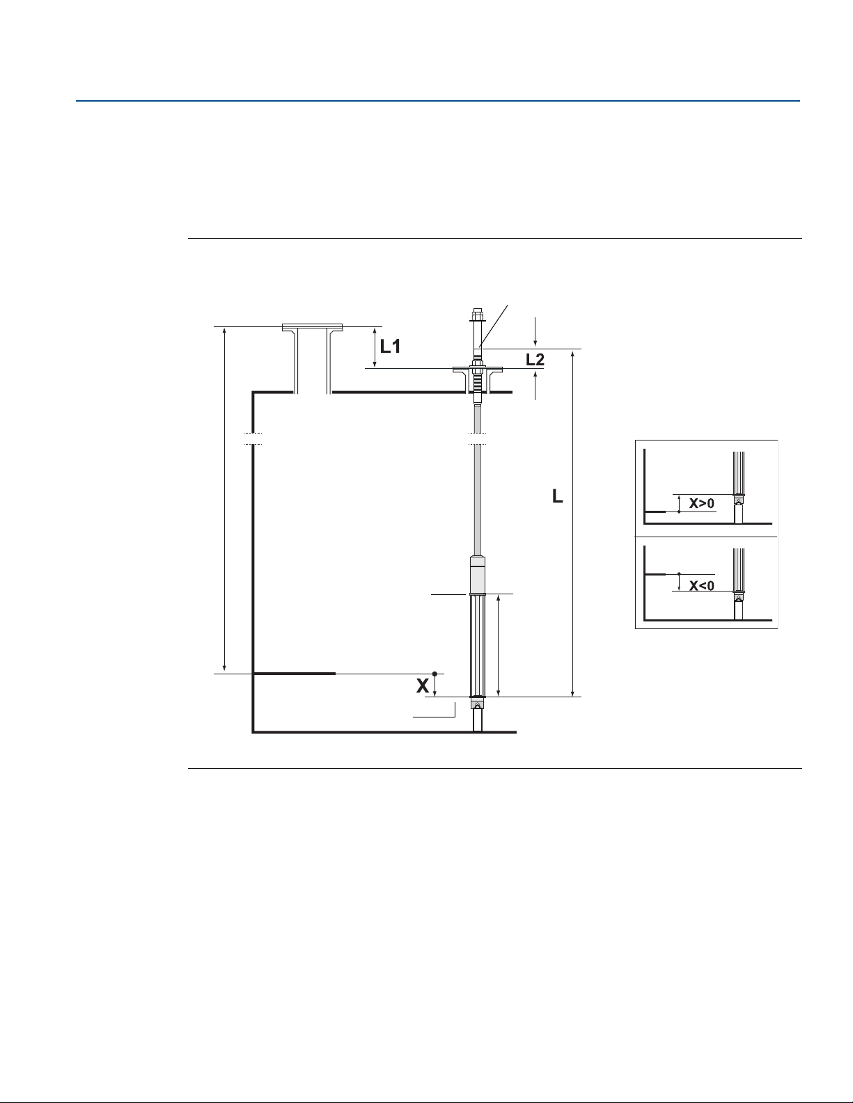
Reference Manual
Tank Zero Level
Tank Reference Point
Upper Reference Point
Water Zero Level
Upper Sensor Limit (100%)
Lower Sensor Limit (0%)
Mark
Level offset
Tank Reference Height (R)
Active length
(L
A
)
00809-0100-2240, Rev EA
5.3.3 Water Level Sensor measuring range
Reference Points
The Water Level Sensor has two reference points, the Upper Reference Point and the Water Zero Level,
which are marked on the probe. The positions are given in Figure 5-5 below:
Figure 5-5. Tank geometry for the water level sensor
Configuration/Operation
May 2020
Configuration/Operation
Level offset
The Level Offset X, referred to as the distance between Tank Zero Level and Water Zero Level, needs to be
considered when configuring the WLS. X can be calculated from known tank distances as described in
“Converting from WLS to tank reference system” on page 61. The various distances are illustrated in
Figure 5-5 and Figure 5-7 on page 62.
59
Page 72
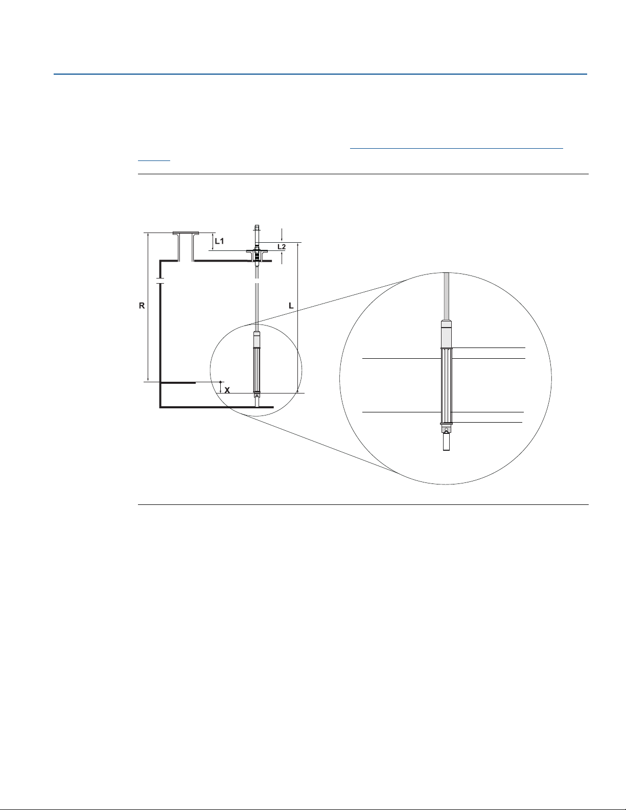
Configuration/Operation
Upper dead zone
Upper Measurement
Limit
Lower Measurement
Limit
Lower dead zone
May 2020
Upper and lower dead zone
The Upper Dead Zone and the Lower Dead Zone are regions within the active length of the water level
sensor which can be used to reduce the measurement range. This can be useful in case there is no
distinct interface between water and oil. See the Rosemount Tank Gauging System Configuration
Manual for information about how to configure the Dead Zones. See also Figure 5-7 on page 62.
Figure 5-6. WLS Measurement Limit and Dead Zones
Reference Manual
00809-0100-2240, Rev EA
60
Configuration/Operation
Page 73

Reference Manual
00809-0100-2240, Rev EA
Converting from WLS to tank reference system
To convert from the reference system of the water level sensor (WLS) to the reference system of the tank,
the distance X needs to be calculated by using the following formula:
X = (R-L1) - (L-L2)
X=distance between the Tank Zero Level and the Water Zero Level.
L=distance between Water Zero Level and mark on the upper part of the WLS.
R= Ta nk R ef ere nce He ig ht. Th is i s t he d ista nc e be tw een the Tank Reference Point and the Tank Zero Level.
L1=distance between the Tank Reference Point and the temperature sensor flange.
L2=distance between the mark on the top of the WLS and the temperature sensor flange.
See Figure 5-5 on page 59 for illustration of the different geometry parameters related to the water level
sensor.
Sensor limits
Conversion from the WLS reference system to the tank reference system is handled by the Rosemount
2240S transmitter. In the tank reference system, the Lower Sensor Limit (0%) and the Upper Sensor Limit
(100%) are given by the following formulas:
Configuration/Operation
May 2020
Upper Sensor Limit (100%) = L
Lower Sensor Limit (0%) = X
where L
Level and the Tank Zero Level (Minimum Water Distance) as described above. See Figure 5-5 on page 59
and examples in section “Configuration examples” on page 63.
is the active length of the Water Level Sensor, and X is the distance between the Water Zero
A
A
+ X
Upper and lower measurement limit
In case Upper and Lower Dead Zones are used to reduce the measurement range (see “Upper and lower
dead zone” on page 60), the resulting measurement limits are calculated using the following formulas:
Upper Measurement Limit (100%) = (L
Lower Measurement Limit (0%) = X + LDZ,
where
L
=active length of the water level sensor
A
UDZ=Upper Dead Zone
LDZ=Lower Dead Zone
See Figure 5-6 on page 60 for an illustration of how the measurement range is affected by the Upper and
Lower Dead Zones.
+ X) - UDZ
A
Configuration/Operation
61
Page 74
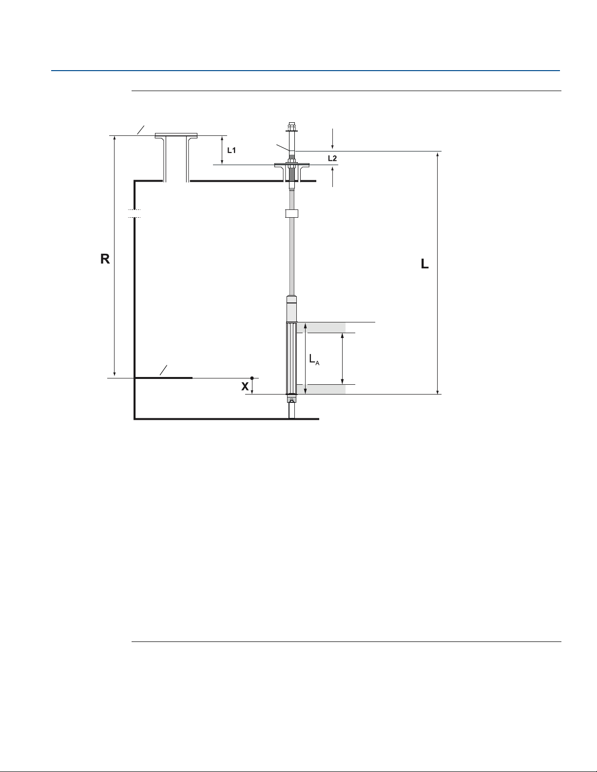
Configuration/Operation
F
G
A
B
E
C
D
H
I
K
May 2020
Figure 5-7. Measurement range and geometry parameters
Reference Manual
00809-0100-2240, Rev EA
62
A. Upper Sensor Limit (100%)
B. Lower Sensor Limit (0%)
C. Upper measurement Limit
D. Measurement range
E. Lower measurement Limit
F. Tank Zero Level
G. Tank Reference Point
H. Upper Dead Zone
I. Lower Dead Zone
K. Upper Reference Point
L. Distance between Water Zero Level and mark on the upper part of the WLS
L1. Distance between the Tank Reference Point and the temperature sensor flange
L2. Distance between the mark on the top of the WLS and the temperature sensor flange
X. Level offset
R. Tank Reference Height. The distance between the Tank Reference Point and Tank Zero Level.
Configuration/Operation
Page 75
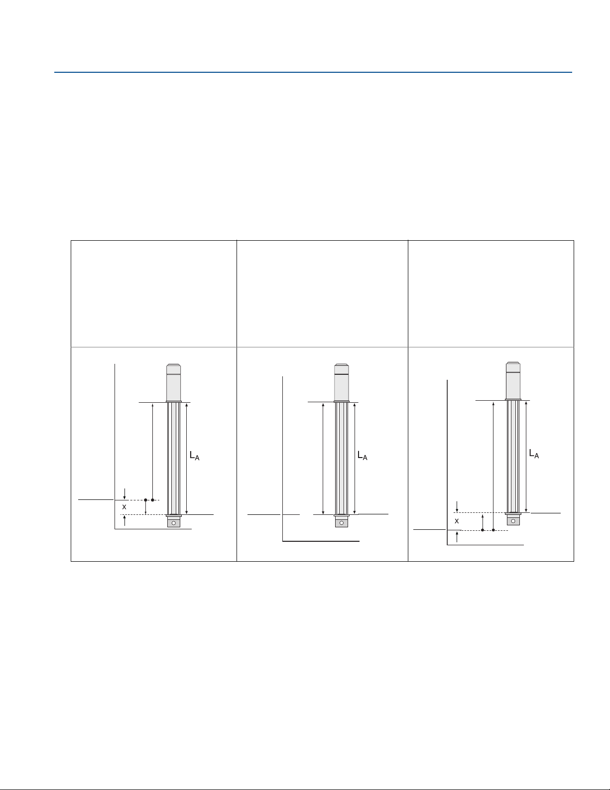
Reference Manual
Tank Zero
Level
Water Zero
Level
X<0
100%
0%
Tank Zero
Level
100%
0%
Water Zero
Level
X=0
Water Zero
Level
X>0
Tank Zero
Level
100%
0%
00809-0100-2240, Rev EA
Configuration examples
Configuration of the water level sensor can basically be divided into three different cases as illustrated in
Table 5-2 below.
X<0: Water Zero Level is located below the Tank Zero Level.
X=0: Water Zero Level is located at the same position as the Tank Zero Level.
X>0: Water Zero Level is located above the Tank Zero Level.
Table 5-2. WLS Configuration
Configuration/Operation
May 2020
Water Zero Level (0%) is below Tank
Zero Level:
X<0
Example:
LA=500 mm, X= -50 mm.
LSL (0%)= -50 mm.
USL(100%) = 500 + (-50)=450 mm.
Water Zero Level (0%) is equal to Tank
Zero Level:
X=0
Example:
LA=500 mm, X=0 mm.
LSL (0%) = 0 mm.
USL (100%) = 500 mm.
Water Zero Level (0%) is above Tank
Zero Level:
X>0
Example:
LA=500 mm, X=70 mm.
LSL (0%) = 70 mm.
USL (100%)= 500 + 70=570 mm.
Configuration/Operation
LSL=Lower Sensor Limit
USL=Upper Sensor Limit
L
=Active Length
A
63
Page 76
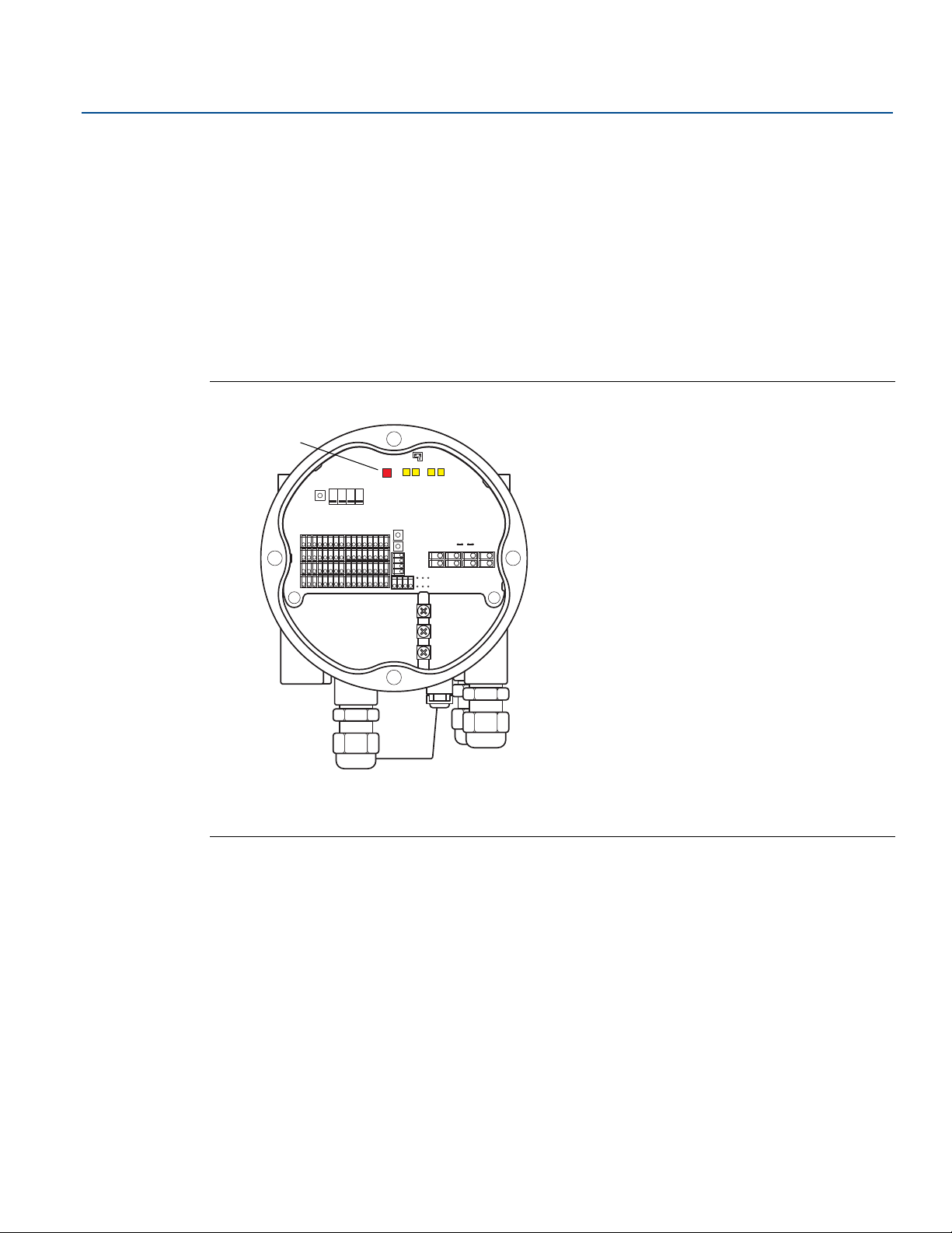
Configuration/Operation
A
May 2020
5.4 LED signals
The Rosemount 2240S Multi-input Temperature Transmitter is equipped with Light Emitting Diodes
(LED) in order to indicate status and communication.
5.4.1 Status LED
The status LED indicates:
normal operation by flashing every other second
calibration of the water level sensor, see “Water Level Sensor calibration” on page 57
error codes
Figure 5-8. Status LED
Reference Manual
00809-0100-2240, Rev EA
64
A. Status LED
Error codes
The status LED indicates error codes by using different blinking sequences. In normal operation the LED
flashes once every other second. When an error occurs, the LED flashes a sequence that corresponds to a
code number followed by a five second pause. This sequence is continuously repeated (for more
information see “Device error LED signals” on page 117).
Configuration/Operation
Page 77
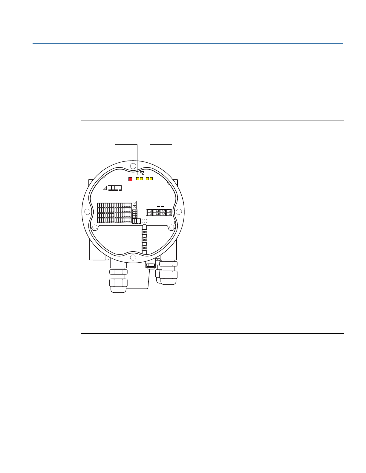
Reference Manual
A B
00809-0100-2240, Rev EA
5.4.2 Communication LEDs
There are two pairs of LEDs that indicate communication status for the Rosemount 2240S Multi-input
Temperature Transmitter:
when a Water Level Sensor (WLS) is connected, two LED signals indicate that measurement and status
information is communicated over the Sensor bus to the temperature transmitter
two LEDs indicate that the temperature transmitter communicates with a Rosemount 2410 Tank Hub
over the Tankbus
Figure 5-9. Communication LEDs
Configuration/Operation
May 2020
Configuration/Operation
A: WLS - receive and transmit
B. Tankbus - receive and transmit
65
Page 78
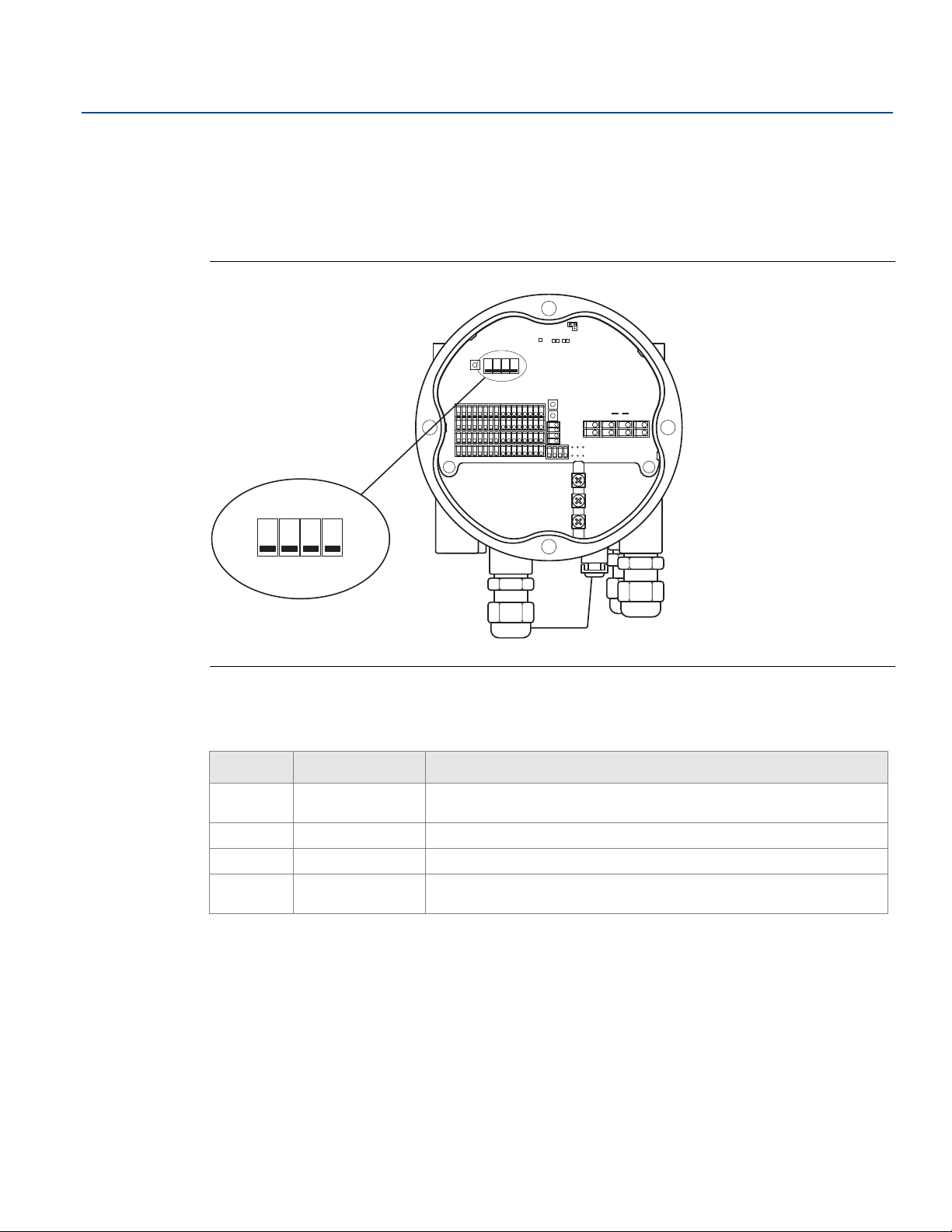
Configuration/Operation
123
4
On
Off
DIP Switches
May 2020
5.5 Switches and reset buttons
5.5.1 DIP Switches
The Rosemount 2240S is equipped with four DIP switches, see Figure 5-10.
Figure 5-10. DIP Switches
Reference Manual
00809-0100-2240, Rev EA
The switches control the following settings:
Table 5-3. DIP Switches
Number Function Description
1
2
3
4
SIMULATE
WRITE PROTECT Enables write protection of configuration data.
SPARE Not used
AVERAGING RTD
Enables simulation of temperature measurements and Field diagnostic
alerts.
Enables the use of an average temperature sensor, see “Tank average
temperature calculation” on page 55.
The simulate switch
The Simulate switch can be used to simulate a resistance value from temperature elements. For
F
OUNDATION fieldbus systems it enables simulation of Field Diagnostics alerts as well.
The write protect switch
The Write Protect switch prevents unauthorized configuration changes by locking the Rosemount
2240S database registers.
66
Configuration/Operation
Page 79
Reference Manual
00809-0100-2240, Rev EA
Configuration using the Average DIP switch
The Average switch enables configuration of the Rosemount 2240S according to the default settings in
Table 5-4:
Table 5-4. Configuration Parameters
Configuration/Operation
May 2020
Configuration
Parameter
Element Type Average Spot
Element Wiring
Conversion Method Cu90 Pt100
Switch in on position (Average) Switch in off position (default)
Common Return
See Figure 4-9 on page 49
Common Return
See Figure 4-9 on page 49
In the TankMaster WinSetup configuration tool, default sensor configuration can be enabled in the
configuration window for the Rosemount 2240S transmitter (2240 MTT Temperature Sensor tab in the
22XX ATD window).
In case the installation does not match the default setting, you will have to configure the temperature
sensor manually. See configuration of ATD devices in the Rosemount Tank Gauging System
Configuration Manual for more information.
Note
Manual configuration may override the switch settings.
For more information on the various configuration parameters, see “Basic configuration” on page 54.
Configuration/Operation
67
Page 80
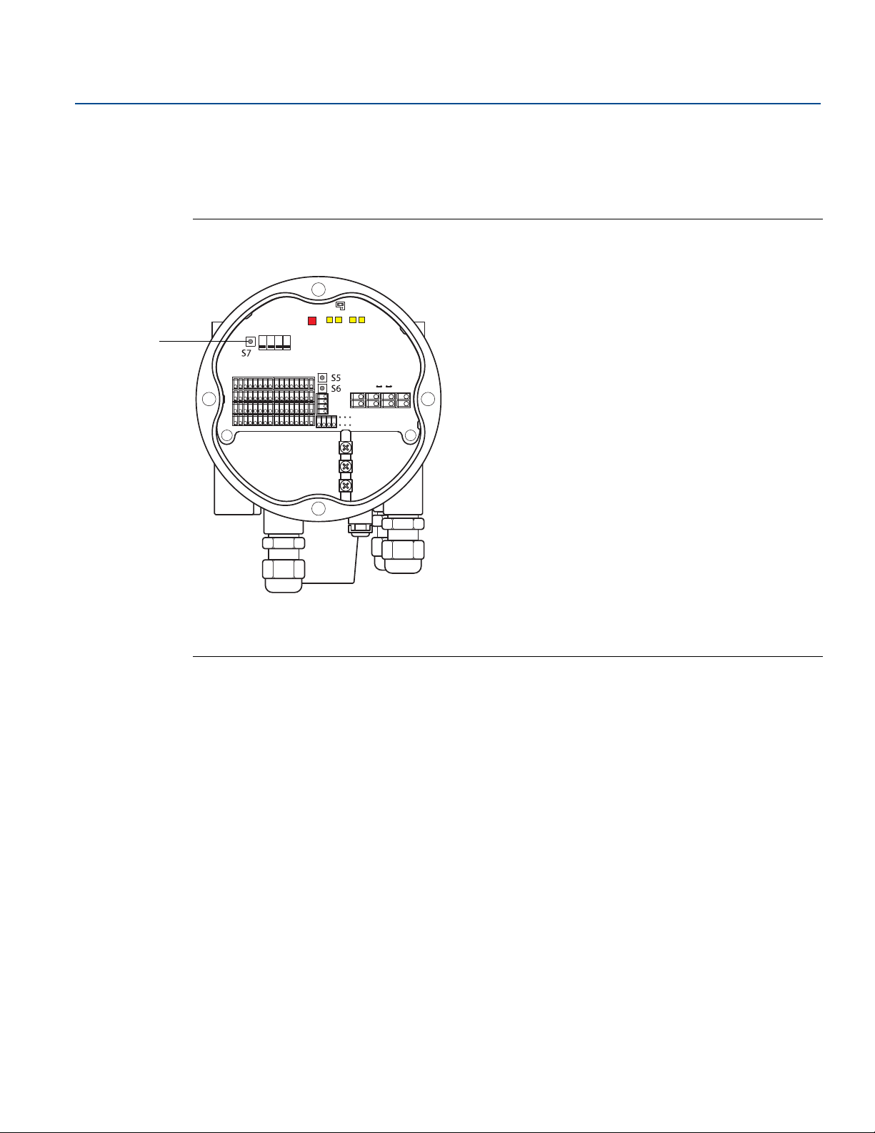
Configuration/Operation
A
May 2020
5.5.2 Reset button
Use the reset button to force a restart of the processor (for more information see “Reset and WLS
calibration” on page 116).
Figure 5-11. Reset button
Reference Manual
00809-0100-2240, Rev EA
A: Reset
68
Configuration/Operation
Page 81

Reference Manual
00809-0100-2240, Rev EA
Configuration/Operation
5.6 Configuration using TankMaster WinSetup
The TankMaster software package provides you with powerful and easy-to-use tools for installation and
configuration of a Rosemount Tank Gauging system. See the Rosemount Tank Gauging System
Configuration Manual for more information on how to configure Auxiliary Tank Devices (ATD) such as the
Rosemount 2240S.
5.6.1 Advanced configuration
Average temperature calculation weight factor
You can specify a weight factor for each temperature element used in the tank average temperature
calculation. This allows you to rate selected temperature elements with a larger impact on the average
temperature calculation than the other elements. This is primarily used for LPG tanks.
Conversion methods
When using a resistance temperature element, the resistance values can be converted to temperature
values by using:
a linearization table
a formula
an individual formula for each temperature element
May 2020
Adjustment after sensor calibration
If the temperature sensor was ordered with sensor calibration including Callendar-Van Dusen constants
the constants must be entered for each individual element using the conversion method "User Defined
Individual Formula" to achieve maximum accuracy.
See the Rosemount Tank Gauging System Configuration Manual
for more information.
Configuration/Operation
69
Page 82

Configuration/Operation
May 2020
5.7 FOUNDATION™ fieldbus overview
This section provides a brief overview of FOUNDATION fieldbus block operation with the Rosemount 2240S
Multi-Input Temperature Transmitter.
Reference Manual
00809-0100-2240, Rev EA
For detailed information about F
Rosemount 2240S Series, refer to Appendix C: F
Block Manual (Document No. 00809-0100-4783).
5.7.1 Block operation
Function blocks within the fieldbus device perform the various functions required for process control.
Function blocks perform process control functions, such as analog input (AI) functions, as well as proportional-integral derivative (PID) functions. The standard function blocks provide a common structure for
defining function block inputs, outputs, control parameters, events, alarms, and modes, and combining
them into a process that can be implemented within a single device or over the fieldbus network. This
simplifies the identification of characteristics that are common to function blocks.
In addition to function blocks, fieldbus devices contain two other block types to support the function
blocks. These are the Resource block and the Transducer block.
Resource blocks contain the hardware specific characteristics associated with a device; they have no
input or output parameters. The algorithm within a resource block monitors and controls the general
operation of the physical device hardware. There is only one resource block defined for a device.
Transducer blocks connect function blocks to local input/output functions. They read sensor hardware
and write to effector (actuator) hardware.
Resource block
The Resource block contains diagnostic, hardware, electronics, and mode handling information. There
are no linkable inputs or outputs to the Resource block.
OUNDATION fieldbus technology and function blocks used in the
OUNDATION
™ FIELDBUS BLOCK INFORMATION
and the FOUNDATION Fieldbus
Measurement transducer block (TB1100)
The Measurement transducer block contains parameters for configuration of the Rosemount 2240S for
temperature measurements as well as temperature measurement data. It contains device information
including diagnostics and the ability to configure, set to factory defaults and restart the temperature
transmitter.
Register transducer block (TB1200)
The Register transducer block allows a service engineer to access all database registers in the device.
Average Temperature transducer block (TB1300)
The Average Temperature transducer block contains parameters for configuration of average
temperature calculations for the 2240S Multi-Input Temperature Transmitter.
70
Configuration/Operation
Page 83
Reference Manual
OUT=The block output value and status
OUT_D=Discrete output that signals a selected
alarm condition
OUT_D
OUT
A
00809-0100-2240, Rev EA
Analog Input block
Figure 5-12. Analog-Input Block
The Analog Input (AI) function block processes field device measurements and makes them available to
other function blocks. The output value from the AI block is in engineering units and contains a status
indicating the quality of the measurement. The measuring device may have several measurements or
derived values available in different channels. Use the channel number to define the variable that the AI
block processes and passes on to linked blocks. For further information refer to “Analog input block” on
page 163 and “Analog Input block” on page 77.
Configuration/Operation
May 2020
Multiple Analog Input block
The Multiple Analog Input (MAI) block makes the temperature elements available to other function
blocks.
PID block
The PID function block combines all of the necessary logic to perform proportional/integral/derivative
(PID) control. The block supports mode control, signal scaling and limiting, feed forward control,
override tracking, alarm limit detection, and signal status propagation.
The block supports two forms of the PID equation: Standard and Series. You can choose the appropriate
equation using the MATHFORM parameter. The Standard ISA PID equation is the default selection.
Input Selector block
The Input Selector (ISEL) function block can be used to select the first good, Hot Backup, maximum,
minimum, or average of as many as eight input values and place it at the output. The block supports
signal status propagation.
Integrator block
The Integrator (INT) function block integrates one or two variables over time.
This block will accept up to two inputs, has six options how to totalize the inputs, and two trip outputs.
The block compares the integrated or accumulated value to pre-trip and trip limits and generates
discrete output signals when the limits are reached.
Arithmetic block
The Arithmetic (ARTH) function block provides the ability to configure a range extension function for a
primary input. It can also be used to compute nine different arithmetic functions.
Configuration/Operation
71
Page 84

Configuration/Operation
May 2020
Control Selector block
The Control Selector function block selects one of two or three inputs to be the output. The inputs are
normally connected to the outputs of PID or other function blocks. One of the inputs would be
considered Normal and the other two overrides.
Output Splitter block
The Output Splitter function block provides the capability to drive two control outputs from a single
input. It takes the output of one PID or other control block to control two valves or other actuators.
Analog output block
The Analog Output function block accepts an output value from a field device and assigns it to a
specified I/O channel. For further information refer to “Analog Output block” on page 83 and “Analog
output block” on page 167.
Function block summary
The following function blocks are available for the Rosemount 2240S Series:
Analog Input (AI)
Analog Output (AO)
Multiple Analog Input (MAI)
Input Selector (ISEL)
Proportional/Integral/Derivative (PID)
Output Splitter (OS)
Signal Characterizer (SGCR)
Integrator (INT)
Arithmetic (ARTH)
Control Selector (CS)
Reference Manual
00809-0100-2240, Rev EA
72
For detailed information about F
OUNDATION fieldbus technology and function blocks used in the
Rosemount 2240S Series, refer to the F
00809-0100-4783).
OUNDATION Fieldbus Block Manual (Document No.
Configuration/Operation
Page 85

Reference Manual
00809-0100-2240, Rev EA
5.8 Device capabilities
5.8.1 Link active scheduler
The Rosemount 2240S can be designated to act as the backup Link Active Scheduler (LAS) in the event
that the LAS is disconnected from the segment. As the backup LAS, the Rosemount 2240S will take over
management of communications until the host is restored.
The host system may provide a configuration tool specifically designed to designate a particular device
as a backup LAS. Otherwise, this can be configured manually.
5.8.2 Device addressing
FOUNDATION fieldbus devices use addresses divided into four sub ranges as shown in Table 5-5.
Configuration/Operation
May 2020
Table 5-5. Address Ranges for F
Address range
(decimal)
0 through 15 00 through 0F Reserved
16 through 247 10 through F7 Permanent devices
248 through 251 F8 through FB
252 through 255 FC through FF
Address range
(hexadecimal)
OUNDATION Fieldbus Devices
Allocation
New or decommissioned
devices
Temporary (“visitor”) devices.
Example: 375/475
communicator
Configuration/Operation
73
Page 86
Configuration/Operation
May 2020
5.8.3 Capabilities
Virtual Communication Relationship (VCRs)
There are a total of 20 VCRs. One is permanent and 19 are fully configurable by the host system. 40 link
objects are available.
Table 5-6. Communication Parameters
Network Parameter Value
Slot Time 8
Maximum Response Delay 5
Minimum Inter PDU Delay 8
Block Execution Times
Table 5-7. Execution Times
Reference Manual
00809-0100-2240, Rev EA
Block Execution time (ms)
Multiple Analog Input (MAI) 15
Analog Input (AI) 10
Analog Output 10
Proportional/Integral/Derivative (PID) 15
Signal Characterizer (SGCR) 10
Integrator (INT) 10
Arithmetic (ARTH) 10
Input Selector (ISEL) 10
Control Selector (CS) 10
Output Splitter (OS) 10
74
Configuration/Operation
Page 87
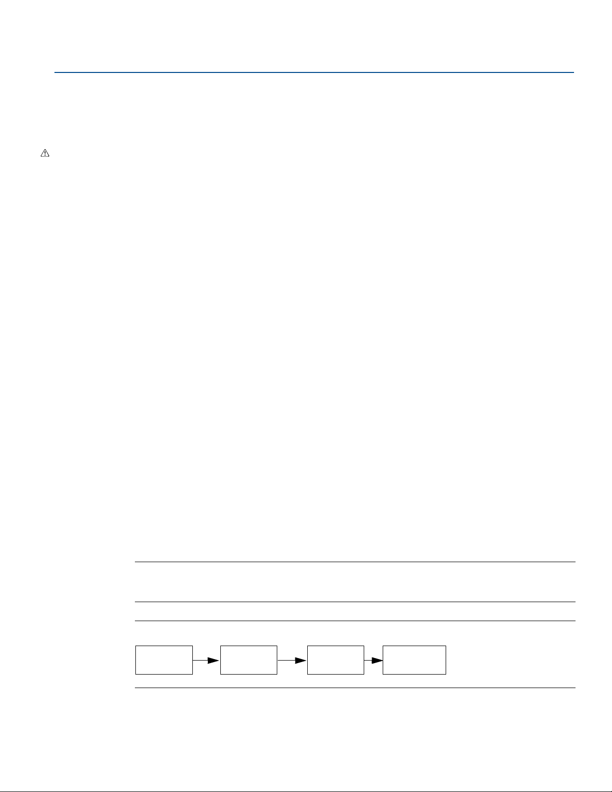
Reference Manual
Resource
Block
Transducer
Block
Analog Input
(AI Block)
Other function
blocks
00809-0100-2240, Rev EA
5.9 General block information
5.9.1 Modes
Changing modes
To change the operating mode, set the MODE_BLK.TARGET to the desired mode. After a short delay, the
parameter MODE_BLOCK.ACTUAL should reflect the mode change if the block is operating properly.
Permitted modes
It is possible to prevent unauthorized changes to the operating mode of a block. To do this, configure
MODE_BLOCK.PERMITTED to allow only the desired operating modes. It is recommended to always
select OOS as one of the permitted modes.
Types of modes
For the procedures described in this manual, it will be helpful to understand the following modes:
AUTO
Configuration/Operation
May 2020
The functions performed by the block will execute. If the block has any outputs, these will continue to
update. This is typically the normal operating mode.
Out of Service (OOS)
The functions performed by the block will not execute. If the block has any outputs, these will typically
not update and the status of any values passed to downstream blocks will be “BAD”. To make some
changes to the configuration of the block, change the mode of the block to OOS. When the changes are
complete, change the mode back to AUTO.
MAN
In this mode, variables that are passed out of the block can be manually set for testing or override
purposes.
Other types of modes
Other types of modes are Cas, RCas, ROut, IMan and LO. Some of these may be supported by different
function blocks in the Rosemount 2240S. For more information, see the Function Block manual,
document 00809-0100-4783.
Note
When an upstream block is set to OOS, this will impact the output status of all downstream blocks.
Figure 5-13 below depicts the hierarchy of blocks.
Configuration/Operation
Figure 5-13. Block Hierarchy
75
Page 88

Configuration/Operation
May 2020
5.9.2 Block instantiation
The Rosemount 2240S supports the use of Function Block Instantiation. This means that the number of
blocks and block types can be defined to match specific application needs.The number of blocks that can
be instantiated is only limited by the amount of memory within the device and the block types that are
supported by the device. Instantiation does not apply to standard device blocks like the Resource and
Transducer Blocks.
By reading the parameter “FREE_SPACE” in the Resource block you can determine how many blocks you
can instantiate. Each block that you instantiate takes up 4.6% of the “FREE_SPACE”.
Block instantiation is done by the host control system or configuration tool, but not all hosts implement
this functionality. Please refer to your specific host or configuration tool manual for more information.
5.9.3 Factory configuration
The following fixed configuration of function blocks is provided:
Table 5-8. Available Function Blocks for the Rosemount 2240S
Function Block Index Default Tag Available
Analog Input
Analog Input 1500 AI 1500 Default, permanent
Analog Input 1600 AI 1600 Default, permanent
(1)
1400 AI 1400 Default, permanent
Reference Manual
00809-0100-2240, Rev EA
Analog Input 1700 AI 1700 Default, permanent
Analog Input 1800 AI 1800 Default, permanent
Analog Input 1900 AI 1900 Default, permanent
Analog Output
Multiple Analog Input 2100 MAI 2100 Default, permanent
Multiple Analog Input 2200 MAI 2200 Default, permanent
Input Selector 2300 ISEL 2300 Default, deletable
Input Selector 2400 ISEL 2400 Default, deletable
PID 2500 PID 2500 Default, deletable
Output Splitter 2600 OSPL 2600 Default, deletable
Signal Characterizer 2700 CHAR 2700 Default, deletable
Integrator 2800 INTEG 2800 Default, deletable
Arithmetic 2900 ARITH 2900 Default, deletable
Control Selector 3000 CSEL 3000 Default, deletable
1. See “Factory supplied AI blocks” on page 79 for more information.
2. See “Analog Output block” on page 83 for more information.
(2)
2000 AO 2000 Default, permanent
76
Configuration/Operation
Page 89
Reference Manual
00809-0100-2240, Rev EA
5.10 Analog Input block
5.10.1 Configure the AI block
A minimum of four parameters are required to configure the AI Block. The parameters are described
below with example configurations shown at the end of this section.
CHANNEL
Select the channel that corresponds to the desired sensor measurement:
Table 5-9. AI Block Channels for the Rosemount 2240S
Configuration/Operation
May 2020
AI Block Parameter
Internal Temperature 1 CHANNEL_HOUSING_TEMPERATURE
Auxiliary device value 2 CHANNEL_SB_VALUE
Water level 3 CHANNEL_WATER_LEVEL
Pressure 4 CHANNEL_PRESSURE
Average liquid temperature 5 CHANNEL_ TEMP_AVERAGE_LIQUID
Average vapor temperature 6 CHANNEL_ TEMP_AVERAGE_VAPOR
Average Tank Temperature 7 CHANNEL_ TANK_TEMPERATURE
TB Channel
Value
Process Variable
L_TYPE
The L_TYPE parameter defines the relationship of the transmitter measurement (Housing Temperature,
Auxiliary Device Value, Water Level, Pressure, Average Liquid Temperature, Average Vapor Temperature,
Tank Temperature) to the desired output of the AI Block. The relationship can be direct or indirect root.
Direct
Select direct when the desired output will be the same as the transmitter measurement (Housing
Temperature, Auxiliary Device Value, Water Level, Pressure, Average Liquid Temperature, Average Vapor
Temperature, Tank Temperature).
Configuration/Operation
Indirect
Select indirect when the desired output is a calculated measurement based on the transmitter
measurement (e.g. level value displayed in percentage of full span based on measured product level).
The relationship between the transmitter measurement and the calculated measurement will be linear.
Indirect Square Root
Select indirect square root when the desired output is an inferred measurement based on the
transmitter measurement and the relationship between the sensor measurement and the inferred
measurement is square root.
77
Page 90

Configuration/Operation
May 2020
XD_SCALE and OUT_SCALE
The XD_SCALE and OUT_SCALE each include three parameters: 0%, 100%, and engineering units. Set
these based on the L_TYPE:
L_TYPE is Direct
When the desired output is the measured variable, set the XD_SCALE to represent the operating range of
the process. Set OUT_SCALE to match XD_SCALE.
L_TYPE is Indirect
When an inferred measurement is made based on the sensor measurement, set the XD_SCALE to
represent the operating range that the sensor will see in the process. Determine the inferred
measurement values that correspond to the XD_SCALE 0 and 100% points and set these for the
OUT_SCALE.
L_TYPE is Indirect Square Root
When an inferred measurement is made based on the transmitter measurement and the relationship
between the inferred measurement and sensor measurement is square root, set the XD_SCALE to
represent the operating range that the sensor will see in the process. Determine the inferred
measurement values that correspond to the XD_SCALE 0 and 100% points and set these for the
OUT_SCALE.
Reference Manual
00809-0100-2240, Rev EA
Engineering units
Note
To avoid configuration errors, only select Engineering Units for XD_SCALE and OUT_SCALE that are
supported by the device (see “Supported units” on page 178).
78
Configuration/Operation
Page 91
Reference Manual
00809-0100-2240, Rev EA
5.10.2 Factory supplied AI blocks
The Rosemount 2240S is supplied with six pre-configured AI blocks according to Table 5-10. The block
configuration can be changed if needed.
Table 5-10. Factory Supplied AI Blocks
AI Block Channel L-Type Units
1 CHANNEL_ TEMP_AVERAGE_LIQUID Direct deg C
2 CHANNEL_ TEMP_AVERAGE_VAPOR Direct deg C
3 CHANNEL_ TANK_TEMPERATURE Direct deg C
4 CHANNEL_WATER_LEVEL Direct meter
5 CHANNEL_HOUSING_TEMPERATURE Direct deg C
6 CHANNEL_PRESSURE Direct bar
5.10.3 Modes
Configuration/Operation
May 2020
The AI Function Block supports three modes of operation as defined by the MODE_BLK parameter:
Manual (Man) The block output (OUT) may be set manually
Automatic (Auto) OUT reflects the analog input measurement or the simulated value when simulation
is enabled
Out of Service (O/S) The block is not processed. FIELD_VAL and PV are not updated and the OUT status
is set to Bad: Out of Service. The BLOCK_ERR parameter shows Out of Service. In this mode, you can
make changes to all configurable parameters. The target mode of a block may be restricted to one or
more of the supported modes.
Configuration/Operation
79
Page 92
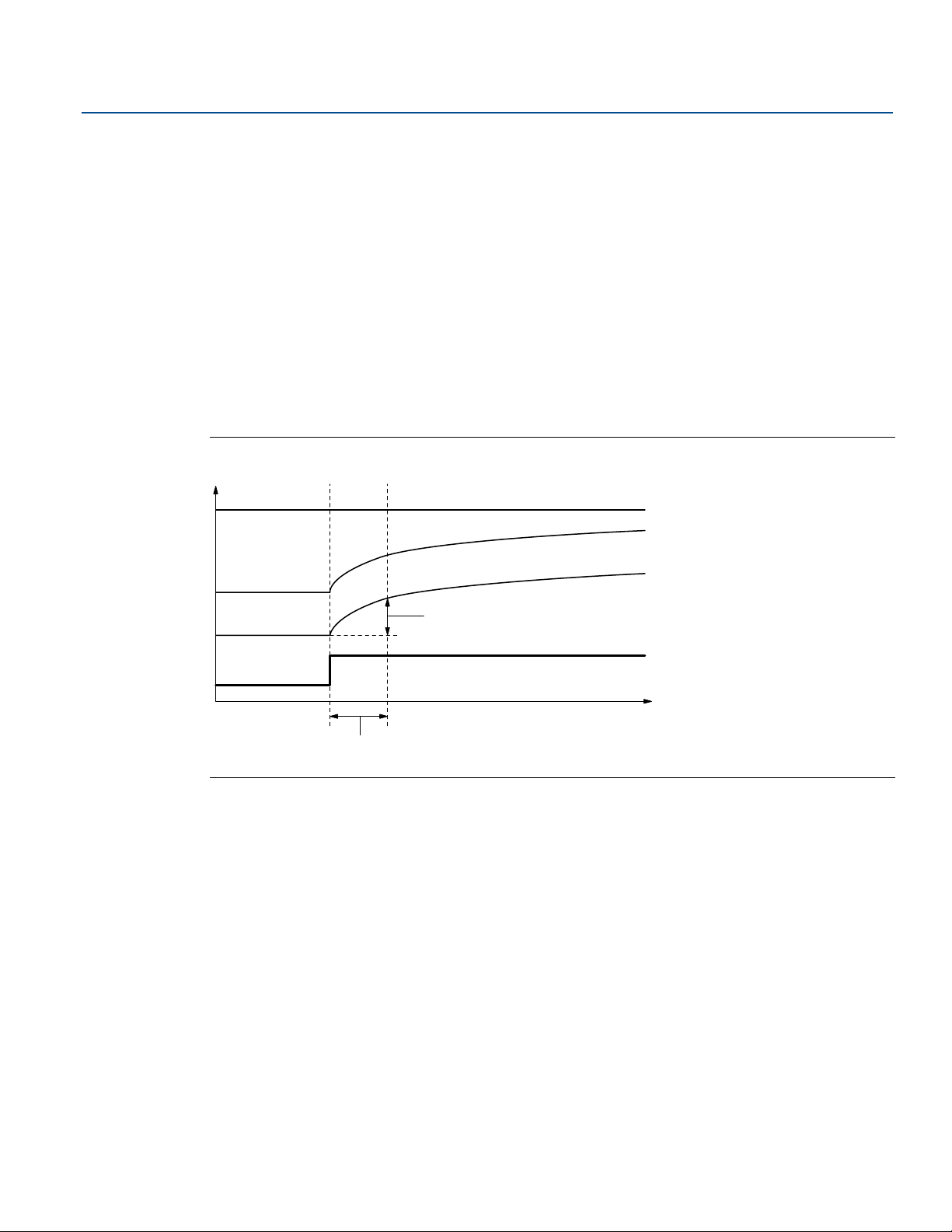
Configuration/Operation
PV_FTIME
63% of Change
OUT (mode in man)
OUT (mode in auto)
PV
Time (seconds)
FIELD_VAL
May 2020
5.10.4 Simulation
To perform lab test of process variables and alerts, you can either change the mode of the AI block to
manual and adjust the output value, or you can enable simulation through the configuration tool and
manually enter a value for the measurement value and its status. In both cases, you must first set the
SIMULATE switch (1) on the field device to the ON position, see “Switches and reset buttons” on page 66.
With simulation enabled, the actual measurement value has no impact on the OUT value or the status.
5.10.5 Filtering
The filtering feature changes the response time of the device to smooth variations in output readings
caused by rapid changes in input. You can adjust the filter time constant (in seconds) using the PV_FTIME
parameter. Set the filter time constant to zero to disable the filter feature.
Figure 5-14. Analog Input Function Block Timing Diagram
Reference Manual
00809-0100-2240, Rev EA
80
Configuration/Operation
Page 93

Reference Manual
FIELD_VAL
100 Channel Value EU*@0%–
EU*@100% EU*@0%–
--------------------------------------------------------------- -----------------------------
=
* XD_SCALE values
PV Channel Value=
PV
FIELD_VAL
100
-------------------------------
EU**@100% EU**@0%–EU**@0%+=
** OUT_SCALE values
PV
FIELD_VAL
100
-------------------------------
EU**@100% EU**@0%–EU**@0%+=
** OUT_SCALE values
00809-0100-2240, Rev EA
5.10.6 Signal Conversion
You can set the signal conversion type with the Linearization Type (L_TYPE) parameter. You can view the
converted signal (in percent of XD_SCALE) through the FIELD_VAL parameter.
You can choose from direct or indirect signal conversion with the L_TYPE parameter.
Direct
Direct signal conversion allows the signal to pass through the accessed channel input value (or the
simulated value when simulation is enabled).
Indirect
Indirect signal conversion converts the signal linearly to the accessed channel input value (or the
simulated value when simulation is enabled) from its specified range (XD_SCALE) to the range and units
of the PV and OUT parameters (OUT_SCALE).
Configuration/Operation
May 2020
Indirect Square Root
Indirect Square Root signal conversion takes the square root of the value computed with the indirect
signal conversion and scales it to the range and units of the PV and OUT parameters.
When the converted input value is below the limit specified by the LOW_CUT parameter, and the Low
Cutoff I/O option (IO_OPTS) is enabled (True), a value of zero is used for the converted value (PV). This
option is useful to eliminate false readings when the differential pressure measurement is close to zero,
and it may also be useful with zero-based measurement devices such as flow meters.
Note
Low Cutoff is the only I/O option supported by the AI block. You can set the I/O option in Manual or Out
of Service mode only.
Configuration/Operation
81
Page 94
Configuration/Operation
May 2020
5.10.7 Process alarm
Process Alarm detection is based on the OUT value. You can configure the alarm limits of the following
standard alarms:
High (HI_LIM)
High high (HI_HI_LIM)
Low (LO_LIM)
Low low (LO_LO_LIM)
In order to avoid alarm chattering when the variable is oscillating around the alarm limit, an alarm
hysteresis in percent of the PV span can be set using the ALARM_HYS parameter. The priority of each
alarm is set in the following parameters:
HI_PRI
HI_HI_PRI
LO_PRI
LO_LO_PRI
Reference Manual
00809-0100-2240, Rev EA
5.10.8 Alarm priority
Alarms are grouped into five levels of priority:
Table 5-11. Alarm Level Priority
Priority
Number
0 The priority of an alarm condition changes to 0 after the condition that caused
1 An alarm condition with a priority of 1 is recognized by the system, but is not
2 An alarm condition with a priority of 2 is reported to the operator, but does not
3-7 Alarm conditions of priority 3 to 7 are advisory alarms of increasing priority.
8-15 Alarm conditions of priority 8 to 15 are critical alarms of increasing priority.
Priority Description
the alarm is corrected.
reported to the operator.
require operator attention (such as diagnostics and system alerts).
82
Configuration/Operation
Page 95

Reference Manual
00809-0100-2240, Rev EA
5.11 Analog Output block
The Rosemount 2240S is supplied with a pre-configured Analog Output (AO) block according to
Table 5-13. The block configuration can be changed if needed. See “Analog output block” on page 167
for more information.
5.11.1 CHANNEL
Select the channel that corresponds to the desired sensor measurement:
Table 5-12. AO Block Channels for the Rosemount 2240S
Configuration/Operation
May 2020
AO Block
Parameter
Level 1 CHANNEL_LEVEL
Table 5-13. Factory Supplied AO Block for the Rosemount 2240S
AO Block Channel Units
1 CHANNEL_LEVEL m
5.11.2 XD_SCALE
The XD_SCALE includes three parameters: 0%, 100%, and engineering units. Set the XD_SCALE to
represent the unit for the AO block channel value.
TB Channel
Value
Process Variable
Configuration/Operation
83
Page 96
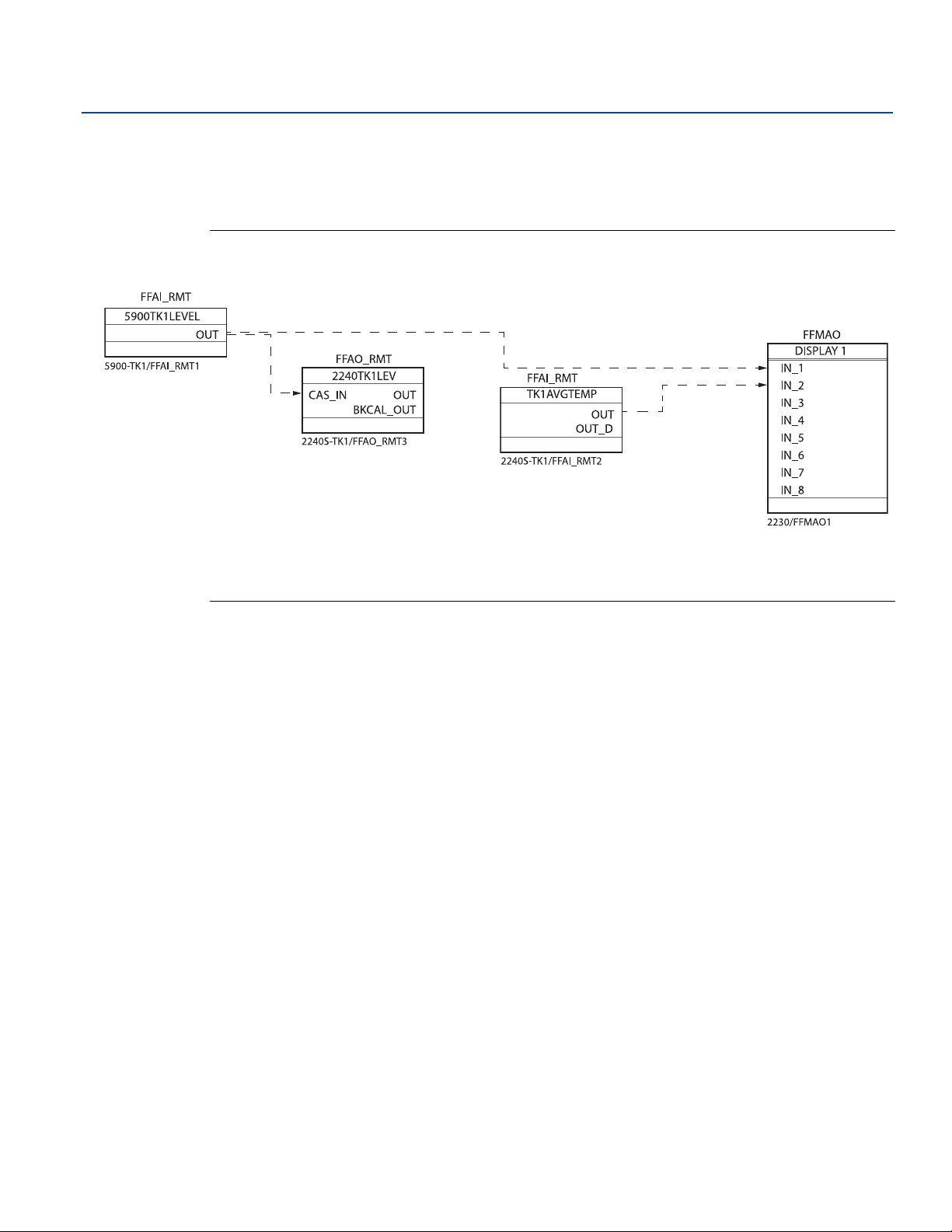
Configuration/Operation
CAS_IN=Remote set point value from another function block
OUT=Block output and status.
May 2020
5.11.3 Application example
This example shows a Rosemount 2240S Multi-Input Temperature Transmitter configured for receiving
level measurement data from a level device such as the Rosemount 5900S Radar Level Gauge.
Figure 5-15. Function block configuration of a Rosemount 2240S using DeltaV™ Control Studio
Reference Manual
00809-0100-2240, Rev EA
Note that XD_SCALE units must be the same in the AI block and the AO block.
84
Configuration/Operation
Page 97

Reference Manual
00809-0100-2240, Rev EA
5.12 Multiple Analog Input blocks
5.12.1 Configure the MAI blocks
The MAI Block is used for temperature element output. It has the ability to process up to eight
temperature element measurements and make them available to other function blocks. The output
values from the MAI block are in engineering units and contain a status.
CHANNEL
Select the channel that corresponds to the desired sensor measurement:
Table 5-14. MAI Block Channels for the Rosemount 2240S
Configuration/Operation
May 2020
MAI Block
Parameter
Temperature
element value
Temperature
element value
TB Channel
Value
1-8
9-16
Process Variable
CHANNEL_TEMP_1 to CHANNEL_TEMP_8
CHANNEL_TEMP_9 to CHANNEL_TEMP_16
Unit
The MAI function block channel data will use the same unit as specified in the parameter TEMPERATURE_UNIT in the Measurement Transducer block TB 1100.
5.12.2 Factory Supplied MAI blocks
The Rosemount 2240S is supplied with two pre-configured MAI blocks according to Table 5-15.
Table 5-15. Factory Supplied MAI Blocks for the Rosemount 2240S
MAI Block Channel Units
1 CHANNEL 1-8 deg C
2 CHANNEL 9-16 deg C
Configuration/Operation
85
Page 98

Configuration/Operation
May 2020
5.13 Resource block
5.13.1 FEATURES and FEATURES_SEL
The FEATURES parameter is read only and defines which features are supported by the Rosemount
2240S. Below is a list of the FEATURES supported by the Rosemount 2240S temperature transmitter.
FEATURES_SEL is used to turn on any of the supported features that are found in the FEATURES
parameter. The default setting of the Rosemount 2240S is HARD W LOCK. Choose one or more of the
supported features if any.
UNICODE
All configurable string variables in the Rosemount 2240S, except tag names, are octet strings. Either
ASCII or Unicode may be used. If the configuration device is generating Unicode octet strings, you must
set the Unicode option bit.
REPORTS
The Rosemount 2240S supports alert reports. The Reports option bit must be set in the features bit
string to use this feature. If it is not set, the host must poll for alerts. If this bit is set, the transmitter will
actively report alerts.
Reference Manual
00809-0100-2240, Rev EA
SOFT W LOCK and HARD W LOCK
Inputs to the security and write lock functions include the hardware security switch, the hardware and
software write lock bits of the FEATURE_SEL parameter, the WRITE_LOCK parameter, and the
DEFINE_WRITE_LOCK parameter.
The WRITE_LOCK parameter prevents modification of parameters within the device except to clear the
WRITE_LOCK parameter. During this time, the block will function normally updating inputs and outputs
and executing algorithms. When the WRITE_LOCK condition is cleared, a WRITE_ALM alert is generated
with a priority that corresponds to the WRITE_PRI parameter.
The FEATURE_SEL parameter enables the user to select a hardware or software write lock or no write lock
capability. To enable the hardware security function, enable the HARDW_LOCK bit in the FEATURE_SEL
parameter. When this bit has been enabled the WRITE_LOCK parameter becomes read only and will
reflect the state of the hardware switch.
In order to enable the software write lock, the SOFTW_LOCK bit must be set in the FEATURE_SEL
parameter. Once this bit is set, the WRITE_LOCK parameter may be set to “Locked” or “Not Locked.”
Once the WRITE_LOCK parameter is set to “Locked” by the software lock, all user requested writes as
determined by the DEFINE_WRITE_LOCK parameter shall be rejected.
Table 5-16 on page 87 displays all possible configurations of the WRITE_LOCK parameter.
86
Configuration/Operation
Page 99
Reference Manual
00809-0100-2240, Rev EA
Table 5-16. Write_Lock Parameter
Configuration/Operation
May 2020
FEATURE_SEL
HARDW_LOCK bit
0 (off) 0 (off) NA 1 (unlocked) Read only All
0 (off) 1 (on) NA 1 (unlocked) Read/Write All
0 (off) 1 (on) NA 2 (locked) Read/Write Function Blocks Only
0 (off) 1 (on) NA 2 (locked) Read/Write None
1 (on) 0 (off)
1 (on) 0 (off) 1 (locked) 2 (locked) Read only Function Blocks Only
1 (on) 0 (off) 1 (locked) 2 (locked) Read only None
1. The hardware and software write lock select bits are mutually exclusive and the hardware select has the highest priority. When the
HARDW_LOCK bit if set to 1 (on), the SOFTW_LOCK bit is automatically set to 0 (off) and is read only.
FEATURE_SEL
SOFTW_LOCK bit
5.13.2 MAX_NOTIFY
The MAX_NOTIFY parameter value is the maximum number of alert reports that the resource can have
sent without getting a confirmation, corresponding to the amount of buffer space available for alert
messages. The number can be set lower, to control alert flooding, by adjusting the LIM_NOTIFY
parameter value. If LIM_NOTIFY is set to zero, then no alerts are reported.
SECURITY
SWITCH
(1)
0
(unlocked)
WRITE_LOCK
1 (unlocked) Read only All
WRITE_LOCK
Read/Write
Write access to blocks
Configuration/Operation
87
Page 100

Configuration/Operation
May 2020
5.13.3 Field diagnostic alerts
The Resource Block acts as a coordinator for Field Diagnostic alerts. There are four alarm parameters
(FD_FAIL_ALM, FD_OFFSPEC_ALM, FD_MAINT_ALM, and FD_CHECK_ALM) which contain information
regarding some of the device errors which are detected by the transmitter software.
There is a FD_RECOMMEN_ACT parameter which is used to display the recommended action text for the
highest priority alarm. FD_FAIL_ALM has the highest priority followed by FD_OFFSPEC_ALM,
FD_MAINT_ALM, and FD_CHECK_ALM which has the lowest priority.
Failure alerts
A Failure alert indicates a condition within a device that will make the device or some part of the device
non-operational. This implies that the device is in need of repair and must be fixed immediately. There
are five parameters associated with FD_FAIL_ALM specifically, they are described below.
FD_FAIL_MAP
This parameter maps conditions to be detected as active for this alarm category. Thus the same
condition may be active in all, some, or none of the four alarm categories. The parameter contains a list
of conditions in the device which makes the device non-operational that will cause an alarm to be sent.
Below is a list of the conditions with the highest priority first. This priority is not the same as the
FD_FAIL_PRI parameter described below. It is hard coded within the device and is not user configurable.
Reference Manual
00809-0100-2240, Rev EA
1. Software Failure
2. Database Error
3. Auxiliary Device Error
4. Electronics Failure - Main Board
5. Memory Failure - FF I/O Board
6. Internal Communication Failure
7. Electronics Failure - FF I/O Board
FD_FAIL_MASK
This parameter will mask any of the failed conditions listed in FD_FAIL_MAP. A bit on means that the
condition is masked out from alarming and being broadcast to the host through the alarm parameter.
FD_FAIL_PRI
Designates the alarming priority of the FD_FAIL_ALM, see “Alarm priority” on page 82. The default is 0
and the recommended values are between 8 and 15.
FD_FAIL_ACTIVE
This parameter displays which of the conditions is active.
FD_FAIL_ALM
88
Alarm indicating a condition within a device which makes the device non-operational.
Configuration/Operation
 Loading...