


 Loading...
Reference Manual PRELIMINARY
00809-XXXX-4811, Rev AA
February 2012
Rosemount 3308
Wireless Guided Wave Radar Level Transmitter
www.rosemount.com
PRELIMINARY

00809-XXXX-4811, Rev AA |
PRELIMINARY |
Reference Manual |
|
February 2012 |
Rosemount 3308 |
|
|
|
Rosemount 3308 |
|
Wireless Guided Wave Radar |
|
Level Transmitter |
Rosemount 3308 Hardware Revision |
1 |
HART® Device Revision |
1 |
Field Communicator Field Device Revision |
Dev v1, DD v1 |
NOTICE
Read this manual before working with the product. For personal and system safety, and for optimum product performance, make sure you thoroughly understand the contents before installing, using, or maintaining this product.
The United States has two toll-free assistance numbers and one international number.
Customer Central
1-800-999-9307 (7:00 a.m. to 7:00 p.m. CST)
North American Response Center
1-800-654-7768 (24 hours a day) Equipment service needs
International
1-952-906-8888
The products described in this document are NOT designed for nuclear-qualified applications.
Using non-nuclear qualified products in applications that require nuclear-qualified hardware or products may cause inaccurate readings.
For information on Rosemount nuclear-qualified products, contact your local Emerson Process Management Sales Representative.
NOTICE
The Rosemount 3308 and all other wireless devices should be installed only after the Smart Wireless Gateway has been installed and is functioning properly. Wireless devices should also be powered up in order of proximity from the Smart Wireless Gateway, beginning with the closest. This will result in a simpler and faster network installation.
www.rosemount.com

PRELIMINARY
Failure to follow these installation guidelines could result in death or serious injury:
• Only qualified personnel should perform the installation
Explosions could result in death or serious injury:
Installation of this transmitter in an explosive environment must be in accordance with the appropriate local, national, and international standards, codes, and practices. Please review the Product Certifications section for any restrictions associated with a safe installation.
•Before connecting a Field Communicator in an explosive atmosphere, ensure the instruments are installed in accordance with intrinsically safe or non-incendive field wiring practices
Process leaks may cause harm or result in death:
•Do not remove the transmitter while in operation
•Install device prior to process start-up
•Install and tighten process connectors before applying pressure
Electrical shock can result in death or serious injury:
•Avoid contact with the leads and terminals. High voltage that may be present on leads can cause electrical shock
This device complies with Part 15 of the FCC Rules. Operation is subject to the following conditions: This device may not cause harmful interference. This device must accept any interference received, including interference that may cause undesired operation. This device must be installed to ensure a minimum antenna separation distance of 20 cm (8 in.) from all persons.
NOTICE
Power Module Considerations
Each Power Module contains two "C" size primary lithium/thionyl chloride batteries. Each battery contains approximately 2.5 grams of lithium, for a total of 5 grams in each pack. Under normal conditions, the battery materials are self-contained and are not reactive as long as the batteries and the pack integrity are maintained. Care should be taken to prevent thermal, electrical or mechanical damage. Contacts should be protected to prevent premature discharge.
Battery hazards remain when cells are discharged.
Power modules should be stored in a clean and dry area. For maximum battery life, storage temperature should not exceed 30° C.
The Power Module may be replaced in a hazardous area. The Power Module has surface resistivity greater than one gigaohm and must be properly installed in the wireless device enclosure. Care must be taken during transportation to and from the point of installation to prevent electrostatic charge build-up.
NOTICE
Shipping considerations for wireless products
The unit was shipped to you without the Power Module installed. Please remove the Power Module prior to shipping the unit.
Each Power Module contains two "C" size primary lithium/thionyl chloride batteries. Primary lithium batteries are regulated in transportation by the U.S. Department of Transportation, and are also covered by IATA (International Air Transport Association), ICAO (International Civil Aviation Organization), and ARD (European Ground Transportation of Dangerous Goods). It is the responsibility of the shipper to ensure compliance with these or any other local requirements. Please consult current regulations and requirements before shipping

00809-XXXX-4811, Rev AA |
PRELIMINARY |
Reference Manual |
|
February 2012 |
Rosemount 3308 |
|
|
|
Table of Contents |
SECTION 1
Introduction
SECTION 2
Transmitter Overview
SECTION 3
Wireless Configuration
SECTION 4
Installation
Safety Messages . . . . . . . . . . . . . . . . . . . . . . . . . . . . . . . . . . . . . . . . . 1-1
Manual Overview . . . . . . . . . . . . . . . . . . . . . . . . . . . . . . . . . . . . . . . . . 1-2
Service Support . . . . . . . . . . . . . . . . . . . . . . . . . . . . . . . . . . . . . . . . . . 1-3
Product Recycling/Disposal . . . . . . . . . . . . . . . . . . . . . . . . . . . . . . . . . 1-3
Safety Messages . . . . . . . . . . . . . . . . . . . . . . . . . . . . . . . . . . . . . . . . . 2-1
Warnings . . . . . . . . . . . . . . . . . . . . . . . . . . . . . . . . . . . . . . . . . . . . 2-1
Rosemount 3308 . . . . . . . . . . . . . . . . . . . . . . . . . . . . . . . . . . . . . . . . . 2-2
Theory of Operation. . . . . . . . . . . . . . . . . . . . . . . . . . . . . . . . . . . . . . . 2-3
Application Examples . . . . . . . . . . . . . . . . . . . . . . . . . . . . . . . . . . . . . 2-3
System Architecture. . . . . . . . . . . . . . . . . . . . . . . . . . . . . . . . . . . . . . . 2-6
Interface . . . . . . . . . . . . . . . . . . . . . . . . . . . . . . . . . . . . . . . . . . . . . 2-7
Vessel Characteristics . . . . . . . . . . . . . . . . . . . . . . . . . . . . . . . . . . . . . 2-9
Heating Coils, Agitators . . . . . . . . . . . . . . . . . . . . . . . . . . . . . . . . . 2-9
Tank Shape . . . . . . . . . . . . . . . . . . . . . . . . . . . . . . . . . . . . . . . . . . 2-9
Components of the Transmitter . . . . . . . . . . . . . . . . . . . . . . . . . . . . . 2-10
Probe Selection Guide. . . . . . . . . . . . . . . . . . . . . . . . . . . . . . . . . . . . 2-11
Transition Zones. . . . . . . . . . . . . . . . . . . . . . . . . . . . . . . . . . . . . . 2-12
Service Support . . . . . . . . . . . . . . . . . . . . . . . . . . . . . . . . . . . . . . . . . 2-13
Product Recycling/Disposal . . . . . . . . . . . . . . . . . . . . . . . . . . . . . . . . 2-13
Safety Messages . . . . . . . . . . . . . . . . . . . . . . . . . . . . . . . . . . . . . . . . . 3-1
Warnings . . . . . . . . . . . . . . . . . . . . . . . . . . . . . . . . . . . . . . . . . . . . 3-1
Wireless Considerations . . . . . . . . . . . . . . . . . . . . . . . . . . . . . . . . . . . 3-2
General. . . . . . . . . . . . . . . . . . . . . . . . . . . . . . . . . . . . . . . . . . . . . . 3-2
Mechanical . . . . . . . . . . . . . . . . . . . . . . . . . . . . . . . . . . . . . . . . . . . 3-3
Electrical . . . . . . . . . . . . . . . . . . . . . . . . . . . . . . . . . . . . . . . . . . . . . 3-4
Power Module Installation . . . . . . . . . . . . . . . . . . . . . . . . . . . . . . . . . . 3-5
Device Configuration . . . . . . . . . . . . . . . . . . . . . . . . . . . . . . . . . . . . . . 3-6
Device Network Configuration . . . . . . . . . . . . . . . . . . . . . . . . . . . . . . . 3-6
AMS . . . . . . . . . . . . . . . . . . . . . . . . . . . . . . . . . . . . . . . . . . . . . . . . 3-7
Field Communicator . . . . . . . . . . . . . . . . . . . . . . . . . . . . . . . . . . . . 3-7
Fast Key Sequences . . . . . . . . . . . . . . . . . . . . . . . . . . . . . . . . . . . 3-7
Remove Power Module . . . . . . . . . . . . . . . . . . . . . . . . . . . . . . . . . . . . 3-7
Safety messages . . . . . . . . . . . . . . . . . . . . . . . . . . . . . . . . . . . . . . . . . 4-1 Installation Procedure . . . . . . . . . . . . . . . . . . . . . . . . . . . . . . . . . . . . . 4-3 Before You Install . . . . . . . . . . . . . . . . . . . . . . . . . . . . . . . . . . . . . . . . 4-4 Software write protect. . . . . . . . . . . . . . . . . . . . . . . . . . . . . . . . . . . 4-4 Mounting Considerations . . . . . . . . . . . . . . . . . . . . . . . . . . . . . . . . . . . 4-5 Process Connection . . . . . . . . . . . . . . . . . . . . . . . . . . . . . . . . . . . . 4-5 Installation of Single Lead Probes in Non-metallic Tanks . . . . . . . 4-7 Mounting in Still pipes/by-pass pipes . . . . . . . . . . . . . . . . . . . . . . . 4-8
www.rosemount.com

PRELIMINARY
Rosemount 3308
Reference Manual
00809-XXXX-4811, Rev AA
February 2012
SECTION 5
Start-Up/Commissioning
SECTION 6
Operation and
Maintenance
Free Space . . . . . . . . . . . . . . . . . . . . . . . . . . . . . . . . . . . . . . . . . . . 4-9 Recommended Mounting Position . . . . . . . . . . . . . . . . . . . . . . . . 4-10 Mechanical Installation . . . . . . . . . . . . . . . . . . . . . . . . . . . . . . . . . . . 4-11 Shortening the Probe . . . . . . . . . . . . . . . . . . . . . . . . . . . . . . . . . . 4-13 Anchoring . . . . . . . . . . . . . . . . . . . . . . . . . . . . . . . . . . . . . . . . . . . 4-15 Mounting a Centering Disc for Pipe Installations . . . . . . . . . . . . . 4-17 LCD Display. . . . . . . . . . . . . . . . . . . . . . . . . . . . . . . . . . . . . . . . . . . . 4-18 General. . . . . . . . . . . . . . . . . . . . . . . . . . . . . . . . . . . . . . . . . . . . . 4-18 LCD Rotation . . . . . . . . . . . . . . . . . . . . . . . . . . . . . . . . . . . . . . . . 4-18 Retrofitting . . . . . . . . . . . . . . . . . . . . . . . . . . . . . . . . . . . . . . . . . . 4-18 LCD Configuration . . . . . . . . . . . . . . . . . . . . . . . . . . . . . . . . . . . . 4-18 Ground the Transmitter . . . . . . . . . . . . . . . . . . . . . . . . . . . . . . . . . . . 4-19 How to Ground the Device . . . . . . . . . . . . . . . . . . . . . . . . . . . . . . 4-19
Safety messages . . . . . . . . . . . . . . . . . . . . . . . . . . . . . . . . . . . . . . . . . 5-1 Device Network Configuration . . . . . . . . . . . . . . . . . . . . . . . . . . . . . . . 5-2 AMS . . . . . . . . . . . . . . . . . . . . . . . . . . . . . . . . . . . . . . . . . . . . . . . . 5-2 Field Communicator . . . . . . . . . . . . . . . . . . . . . . . . . . . . . . . . . . . . 5-2 Configuration Parameters . . . . . . . . . . . . . . . . . . . . . . . . . . . . . . . . . . 5-3 Basic Configuration . . . . . . . . . . . . . . . . . . . . . . . . . . . . . . . . . . . . 5-3 Volume Configuration . . . . . . . . . . . . . . . . . . . . . . . . . . . . . . . . . . . 5-6 Configuration using a Field Communicator . . . . . . . . . . . . . . . . . . . . . 5-8 Basic Configuration . . . . . . . . . . . . . . . . . . . . . . . . . . . . . . . . . . . . . . . 5-9 Transmitter Variables . . . . . . . . . . . . . . . . . . . . . . . . . . . . . . . . . . . 5-9 Measurement Units . . . . . . . . . . . . . . . . . . . . . . . . . . . . . . . . . . . . 5-9 Tank Height . . . . . . . . . . . . . . . . . . . . . . . . . . . . . . . . . . . . . . . . . . 5-9 Probe Length . . . . . . . . . . . . . . . . . . . . . . . . . . . . . . . . . . . . . . . . . 5-9 Probe Type . . . . . . . . . . . . . . . . . . . . . . . . . . . . . . . . . . . . . . . . . . 5-10 Product Dielectric . . . . . . . . . . . . . . . . . . . . . . . . . . . . . . . . . . . . . 5-10 Vapor Dielectric . . . . . . . . . . . . . . . . . . . . . . . . . . . . . . . . . . . . . . 5-10 Measurement Mode . . . . . . . . . . . . . . . . . . . . . . . . . . . . . . . . . . . 5-11 Probe Angle . . . . . . . . . . . . . . . . . . . . . . . . . . . . . . . . . . . . . . . . . 5-11 Maximum Upper Product Thickness. . . . . . . . . . . . . . . . . . . . . . . 5-11 Display . . . . . . . . . . . . . . . . . . . . . . . . . . . . . . . . . . . . . . . . . . . . . 5-11 Volume Configuration . . . . . . . . . . . . . . . . . . . . . . . . . . . . . . . . . . . . 5-13 Transmitter Variables . . . . . . . . . . . . . . . . . . . . . . . . . . . . . . . . . . 5-13 Volume Units . . . . . . . . . . . . . . . . . . . . . . . . . . . . . . . . . . . . . . . . 5-13 Tank Type. . . . . . . . . . . . . . . . . . . . . . . . . . . . . . . . . . . . . . . . . . . 5-13 Tank Dimensions . . . . . . . . . . . . . . . . . . . . . . . . . . . . . . . . . . . . . 5-13 Strapping Table . . . . . . . . . . . . . . . . . . . . . . . . . . . . . . . . . . . . . . 5-13 Verify Operation. . . . . . . . . . . . . . . . . . . . . . . . . . . . . . . . . . . . . . . . . 5-14 Verification by LCD. . . . . . . . . . . . . . . . . . . . . . . . . . . . . . . . . . . . 5-14 Field Communicator Verification. . . . . . . . . . . . . . . . . . . . . . . . . . 5-14 Verification by Gateway . . . . . . . . . . . . . . . . . . . . . . . . . . . . . . . . 5-15 Verification with AMS Wireless Configurator . . . . . . . . . . . . . . . . 5-15 Troubleshooting . . . . . . . . . . . . . . . . . . . . . . . . . . . . . . . . . . . . . . 5-16
Safety Messages . . . . . . . . . . . . . . . . . . . . . . . . . . . . . . . . . . . . . . . . . 6-1
LCD Screen Messages . . . . . . . . . . . . . . . . . . . . . . . . . . . . . . . . . . . . 6-2
Startup Screen Sequence . . . . . . . . . . . . . . . . . . . . . . . . . . . . . . . 6-2
Display Operation . . . . . . . . . . . . . . . . . . . . . . . . . . . . . . . . . . . . . . . . 6-3
Diagnostic Button Screen Sequence . . . . . . . . . . . . . . . . . . . . . . . 6-3
TOC-2
00809-XXXX-4811, Rev AA |
PRELIMINARY |
Reference Manual |
|
February 2012 |
Rosemount 3308 |
|
|
SECTION 7
Service and
Troubleshooting
Network Connection Status Screens . . . . . . . . . . . . . . . . . . . . . . . 6-5
Diagnostic Button Screen Sequence (continued). . . . . . . . . . . . . . 6-6
Alerts . . . . . . . . . . . . . . . . . . . . . . . . . . . . . . . . . . . . . . . . . . . . . . . . . . 6-8
Device Alert Configuration . . . . . . . . . . . . . . . . . . . . . . . . . . . . . . . 6-9
Power Module Replacement . . . . . . . . . . . . . . . . . . . . . . . . . . . . . . . 6-10
Safety messages . . . . . . . . . . . . . . . . . . . . . . . . . . . . . . . . . . . . . . . . . 7-1 Advanced Configuration . . . . . . . . . . . . . . . . . . . . . . . . . . . . . . . . . . . 7-2 User defined Upper Reference Point . . . . . . . . . . . . . . . . . . . . . . . 7-2 Plotting the Measurement Signal . . . . . . . . . . . . . . . . . . . . . . . . . . 7-3 Interface Measurements for Semi-Transparent Bottom Products . 7-5 High Level Rates . . . . . . . . . . . . . . . . . . . . . . . . . . . . . . . . . . . . . . 7-7 Interface Measurements with Fully Immersed Probes . . . . . . . . . . 7-8 Service. . . . . . . . . . . . . . . . . . . . . . . . . . . . . . . . . . . . . . . . . . . . . . . . . 7-9 Level and Distance Calibration. . . . . . . . . . . . . . . . . . . . . . . . . . . . 7-9 Disturbances at the Top of the Tank . . . . . . . . . . . . . . . . . . . . . . 7-10 Amplitude Threshold Settings. . . . . . . . . . . . . . . . . . . . . . . . . . . . 7-12 Logging Measurement Data . . . . . . . . . . . . . . . . . . . . . . . . . . . . . 7-14 Saving the Transmitter Configuration . . . . . . . . . . . . . . . . . . . . . . 7-15 Removing the Transmitter Head. . . . . . . . . . . . . . . . . . . . . . . . . . 7-17 Changing the Probe . . . . . . . . . . . . . . . . . . . . . . . . . . . . . . . . . . . 7-18 Diagnostic Messages. . . . . . . . . . . . . . . . . . . . . . . . . . . . . . . . . . . . . 7-19 Troubleshooting . . . . . . . . . . . . . . . . . . . . . . . . . . . . . . . . . . . . . . 7-19 Errors . . . . . . . . . . . . . . . . . . . . . . . . . . . . . . . . . . . . . . . . . . . . . . 7-20 Warnings . . . . . . . . . . . . . . . . . . . . . . . . . . . . . . . . . . . . . . . . . . . 7-21
APPENDIX A
Reference Data
APPENDIX B
Product Certifications
Safety Messages . . . . . . . . . . . . . . . . . . . . . . . . . . . . . . . . . . . . . . . . . B-1
TOC-3

PRELIMINARY
Rosemount 3308
Reference Manual
00809-XXXX-4811, Rev AA
February 2012
TOC-4

00809-XXXX-4811, Rev AA |
PRELIMINARY |
Reference Manual |
|
February 2012 |
Rosemount 3308 |
|
|
Section 1 |
Introduction |
SAFETY MESSAGES
Safety Messages . . . . . . . . . . . . . . . . . . . . . . . . . . . . . . . . . page 1-1 Manual Overview . . . . . . . . . . . . . . . . . . . . . . . . . . . . . . . . page 1-2 Service Support . . . . . . . . . . . . . . . . . . . . . . . . . . . . . . . . . page 1-3 Product Recycling/Disposal . . . . . . . . . . . . . . . . . . . . . . . page 1-3
Procedures and instructions in this manual may require special precautions to ensure the safety of the personnel performing the operations. Information that raises potential safety issues is indicated by a warning symbol ( ). Refer to the safety messages listed at the beginning of each section before performing an operation preceded by this symbol.
Failure to follow these installation guidelines could result in death or serious injury.
•Make sure only qualified personnel perform the installation.
•Use the equipment only as specified in this manual. Failure to do so may impair the protection provided by the equipment.
Explosions could result in death or serious injury.
•Verify that the operating environment of the transmitter is consistent with the appropriate hazardous locations certifications.
•Before connecting a HART®-based communicator in an explosive atmosphere, make sure the instruments in the loop are installed in accordance with intrinsically safe or non-incendive field wiring practices.
Electrical shock could cause death or serious injury.
•Use extreme caution when making contact with the leads and terminals.
Any substitution of non-recognized parts may jeopardize safety. Repair, e.g. substitution of components etc., may also jeopardize safety and is under no circumstances allowed.
www.rosemount.com

PRELIMINARY
Rosemount 3308
Reference Manual
00809-XXXX-4811, Rev AA
February 2012
MANUAL OVERVIEW
This manual provides installation, configuration and maintenance information for the Rosemount 3308 transmitter.
Section 2: Transmitter Overview
•Theory of operation
•Application examples
•System architecture
•Process and vessel characteristics
•Description of the transmitter
Section 3: Wireless Configuration
•Mounting considerations
•Mechanical installation
•Electrical installation
Section 4: Installation
•Mounting considerations
•Mechanical installation
•Electrical installation
Section 5: Start-Up/Commissioning
•Configuration instructions
•Configuration using the HART Communicator
•Configuration using the RCT software
Section 6: Operation and Maintenance
•Display functionality
•Error messages
•Alarm and write protection
Section 7: Service and Troubleshooting
•Advanced configuration
•Service
•Diagnostic messages
Appendix A: Reference Data
•Specifications
•Ordering Information
Appendix B: Product Certifications
•Examples of labels
•EU conformity
•European ATEX Directive information
•FM approvals
•CSA approvals
•Approval drawings
1-2
00809-XXXX-4811, Rev AA |
PRELIMINARY |
Reference Manual |
|
February 2012 |
Rosemount 3308 |
|
|
SERVICE SUPPORT
To expedite the return process outside of the United States, contact the nearest Emerson Process Management representative.
Within the United States, call the Emerson Process Management Instrument and Valves Response Center using the 1-800-654-RSMT (7768) toll-free number. This center, available 24 hours a day, will assist you with any needed information or materials.
The center will ask for product model and serial numbers, and will provide a Return Material Authorization (RMA) number. The center will also ask for the process material to which the product was last exposed.
|
|
|
|
|
|
|
|
|
|
Individuals who handle products exposed to a hazardous substance can avoid injury if |
|
|
they are informed of and understand the hazard. If the product being returned was |
|
|
exposed to a hazardous substance as defined by Occupational Safety and Health |
|
|
Administration (OSHA), a copy of the required Material Safety Data Sheet (MSDS) for |
|
|
each hazardous substance identified must be included with the returned goods. |
|
|
|
|
|
Emerson Process Management Instrument and Valves Response Center |
|
|
representatives will explain the additional information and procedures |
|
|
necessary to return goods exposed to hazardous substances. |
|
PRODUCT |
Recycling of equipment and packaging should be taken into consideration |
|
RECYCLING/DISPOSAL |
and disposed of in accordance with local and national legislation/regulations. |
|
1-3

PRELIMINARY
Rosemount 3308
Reference Manual
00809-XXXX-4811, Rev AA
February 2012
1-4

00809-XXXX-4811, Rev AA |
PRELIMINARY |
Reference Manual |
|
February 2012 |
Rosemount 3308 |
|
|
Section 2 |
Transmitter Overview |
SAFETY MESSAGES
Warnings
Safety Messages . . . . . . . . . . . . . . . . . . . . . . . . . . . . . . . . . page 2-1 Theory of Operation . . . . . . . . . . . . . . . . . . . . . . . . . . . . . . page 2-3 Application Examples . . . . . . . . . . . . . . . . . . . . . . . . . . . . page 2-3 System Architecture . . . . . . . . . . . . . . . . . . . . . . . . . . . . . . page 2-6 Vessel Characteristics . . . . . . . . . . . . . . . . . . . . . . . . . . . . page 2-9 Probe Selection Guide . . . . . . . . . . . . . . . . . . . . . . . . . . . . page 2-11 Service Support . . . . . . . . . . . . . . . . . . . . . . . . . . . . . . . . . page 2-13 Product Recycling/Disposal . . . . . . . . . . . . . . . . . . . . . . . page 2-13
Instructions and procedures in this section may require special precautions to ensure the safety of the personnel performing the operations. Information that potentially raises safety issues is indicated by a warning symbol ( ). Please refer to the following safety messages before performing an operation preceded by this symbol.
Failure to follow these installation guidelines could result in death or serious injury:
• Only qualified personnel should perform the installation
Explosions could result in death or serious injury:
Installation of this transmitter in an explosive environment must be in accordance with the appropriate local, national, and international standards, codes, and practices. Please review the Product Certifications section for any restrictions associated with a safe installation.
•Before connecting a Field Communicator in an explosive atmosphere, make sure that the instruments are installed in accordance with intrinsically safe or non-incendive field wiring practices
Process leaks may cause harm or result in death:
•Do not remove the transmitter while in operation
•Install the transmitter prior to process start-up
Electrical shock could cause death or serious injury:
•Avoid contact with the leads and terminals. High voltage that may be present on leads can cause electrical shock
This device complies with Part 15 of the FCC Rules. Operation is subject to the following conditions: This device may not cause harmful interference. This device must accept any interference received, including interference that may cause undesired operation. This device must be installed to ensure a minimum antenna separation distance of 20 cm (8 in.) from all persons.
www.rosemount.com

PRELIMINARY
Rosemount 3308
Reference Manual
00809-XXXX-4811, Rev AA
February 2012
ROSEMOUNT 3308
Features of the Rosemount 3308 Wireless Guided Wave Radar include:
•An installation-ready solution that provides a variety of mounting options, transmitter configurations, and switches
•Flexibility to meet your most demanding applications
•Wireless output with >99% data reliability delivers rich HART® data, protected by industry leading security
•Single or dual switch input with logic for limit contact and opposing contact applications
•The integral LCD conveniently displays the primary switch input and diagnostics of the transmitter
•Simple and easy installation practices currently being used for robust installations
Smart Wireless delivers innovative wireless solutions for level measurement and overall transmitter performance
•Self-organizing network delivers information rich data with >99% data reliability and establishes a highly stable network
•Smart Wireless capabilities extend the full benefits of PlantWeb® to previously inaccessible temperature measurement locations
•Emerson SmartPower™ Solutions provide an intrinsically safe Power Module, allowing field replacements without removing the transmitter from the process, keeping personnel safe, and reducing maintenance costs
•Emerson Process Management's layered approach to wireless network security ensures that data transmissions are secure
2-2

00809-XXXX-4811, Rev AA |
PRELIMINARY |
Reference Manual |
|
February 2012 |
Rosemount 3308 |
|
|
THEORY OF OPERATION The Rosemount 3308 Wireless Guided Wave Radar Level Transmitter is a |
|
|
continuous level transmitter that is based on Time Domain Reflectometry |
|
(TDR) principles. Low power nano-second-pulses are guided along a probe |
|
immersed in the process media. When a pulse reaches the surface of the |
|
material it is measuring, part of the energy is reflected back to the transmitter, |
|
and the time difference between the generated and reflected pulse is |
|
converted into a distance from which the total level or interface level is |
|
calculated (see below). |
|
The reflectivity of the product is a key parameter for measurement |
|
performance. A high dielectric constant of the media gives better reflection |
|
and a longer measuring range. A calm surface gives better reflection than a |
|
turbulent surface. |
Figure 2-1. Measurement
Principle.
Signal Amplitude
Reference Pulse 
Level
Interface Level
Time
APPLICATION |
The Rosemount 3308 transmitter is suited for aggregate (total) level |
EXAMPLES |
measurements on most liquids, semi-liquids, and liquid/liquid interfaces. |
|
Guided microwave technology offers highest reliability and precision which |
|
ensure measurements are virtually unaffected by temperature, pressure, |
|
vapor gas mixtures, density, turbulence, bubbling/boiling, low level, varying |
|
dielectric media, pH, and viscosity. |
|
Guided wave radar technology in combination with advanced signal |
|
processing make the Rosemount 3308 transmitter suitable for a wide range of |
|
applications. |
2-3
PRELIMINARY
Rosemount 3308
Reference Manual
00809-XXXX-4811, Rev AA
February 2012
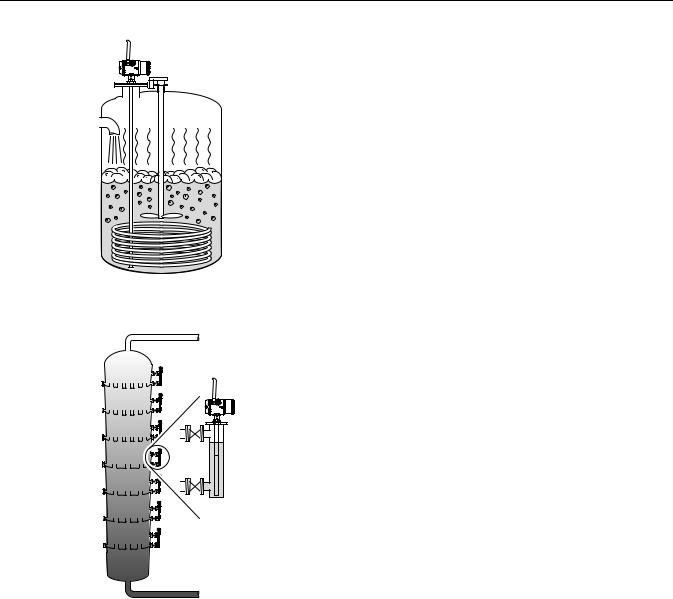
Boiling conditions with vapor and turbulence
For these applications the Coaxial probe is particularly suitable.
Bridle applications
The Rosemount 3308 transmitter is well suited for bridle applications, such as distillation columns.
2-4

00809-XXXX-4811, Rev AA |
PRELIMINARY |
Reference Manual |
|
February 2012 |
Rosemount 3308 |
|
|
Separator tanks
The Rosemount 3308 measures both level and interface level.
Underground tanks
The Rosemount 3308 transmitter is a good choice for underground tanks since it is installed on the tank top with the radar pulse concentrated near the probe. It can be equipped with probes that are unaffected by high and narrow openings or nearby objects.
Small ammonia, NGL and LPG tanks
Guided wave radar technology is a good choice for reliable measurements in small ammonia, NGL and LPG tanks.
2-5

PRELIMINARY
Rosemount 3308
Reference Manual
00809-XXXX-4811, Rev AA
February 2012
SYSTEM
ARCHITECTURE
Figure 2-2. System architecture.
The Rosemount 3308 transmitter is battery powered with wireless communication which means the unit works completely independent.
By using the optional HART Tri-loop, it is possible to convert the HART signal to up to three additional 4-20 mA analog signals.
With the HART protocol it is possible to use multidrop configuration. In this case communication is restricted to digital since current is fixed to the 4 mA minimum value.
The transmitter can be connected to display Rosemount 751 Field Signal Indicator or it can be equipped with an integral display.
The transmitter can easily be configured by using the AMS suite software or by using a Field Communicator. A PC with the Radar Configuration Tool software can also be used for configuration.
For HART communication a minimum load resistance of 250 within the loop is required.
Rosemount 3308 Wireless
Guided Wave Radar Transmitter
Smart Wireless Gateway
Integral
Display
Field Communicator
AMS Suite
2-6
00809-XXXX-4811, Rev AA |
PRELIMINARY |
Reference Manual |
|
February 2012 |
Rosemount 3308 |
Interface |
Rosemount 3308 is the ideal choice for measuring the interface of oil and |
|
water, or other liquids with significant dielectric differences. |
Figure 2-3. Interface |
|
measurement with a |
|
Rosemount 3308 |
|
Level
|
|
|
|
Interface Level |
|
|
|
Level = Interface Level |
|
|
|
|
|
|
|
||
|
|
|
|
|
|
|
|
|
|
|
|
|
|
|
|
|
|
|
|
|
|
|
|
|
|
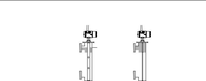
|
All probes can be used for measuring interfaces. The coaxial probe is the preferred choice for clean liquids and when the bridle is not fully immersed. In applications with a fully immersed probe, the twin lead probes are recommended for nozzle installations, and the rigid single lead probe is best for bridle mounting.
For measuring the interface level, the transmitter uses the residual wave of the first reflection. Part of the wave, which was not reflected at the upper product surface, continues until it is reflected at the lower product surface. The speed of this wave depends fully on the dielectric constant of the upper product.
If interface is to be measured, the following criteria have to be fulfilled:
•The dielectric constant of the upper product must be known. The Radar Configuration Tools software has a built-in dielectric constant calculator to assist users in determining the dielectric constant of the upper product.
•The dielectric constant of the upper product must have a lower dielectric constant than the lower product in order to have a distinct reflection.
•The difference between the dielectric constants for the two products must be larger than 10.
•Maximum dielectric constant for the upper product is 10 for the coaxial probe and 5 for twin lead probes.
•The upper product thickness must be larger than 8 inches (0.2 m) for the flexible twin lead probe and 4 inches (0.1 m) for the rigid twin lead and coaxial probes in order to distinguish the echoes of the two liquids.
The maximum allowable upper product thickness/measuring range is primarily determined by the dielectric constants of the two liquids.
Target applications include interfaces between oil/oil-like and water/water-like liquids. For such applications the upper product dielectric constant is low (<3) and the lower product dielectric constant is high (>20), and the maximum measuring range is only limited by the length of the coaxial and rigid twin lead probes.
2-7

PRELIMINARY
Rosemount 3308
Reference Manual
00809-XXXX-4811, Rev AA
February 2012
Emulsion Layers
Sometimes there is an emulsion layer (mix of the products) between the two products which, depending on its characteristics, will affect interface measurements.
Please consult factory for guidelines on how to handle emulsion layers.
2-8
00809-XXXX-4811, Rev AA |
PRELIMINARY |
Reference Manual |
|
February 2012 |
Rosemount 3308 |
|
|
VESSEL |
|
CHARACTERISTICS |
|
Heating Coils, Agitators
Tank Shape
The Rosemount 3308 transmitter is relatively insensitive to objects in the tank since the radar signal is transmitted along a probe.
Avoid physical contact between probes and agitators as well as applications with strong fluid movement unless the probe is anchored. If the probe can move within 1 ft (30 cm) away from any object, such as an agitator, during operation then probe tie-down is recommended.
In order to stabilize the probe for side forces, it is possible to hang a weight at the probe end (flexible probes only) or fix/guide the probe to the tank bottom.
The guided wave radar transmitter is insensitive to the tank shape. Since the radar signal travels along a probe, the shape of the tank bottom has virtually no effect on the measurement performance. The transmitter handles flat or dish-bottom tanks equally well.
2-9
PRELIMINARY
Rosemount 3308
Reference Manual
00809-XXXX-4811, Rev AA
February 2012
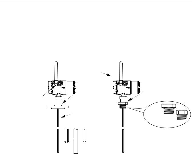
COMPONENTS OF THE TRANSMITTER
Figure 2-4. Transmitter components.
The Rosemount 3308 transmitter has an aluminum transmitter housing which contains advanced electronics for signal processing.
The radar electronics produces an electromagnetic pulse which is guided by the probe.
There are different probe types available for various applications: Flexible Twin Lead, Rigid Single Lead, Flexible Single Lead, and Coaxial.
|
Dual Compartment Housing |
|
Threaded Process |
|
Connections |
Radar Electronics |
Flanged Process |
Connections |
Probe |
BSP (G) |
|
NPT |
||
|
|
|
|
|
|
|
|
|
|
|
|
Rigid |
|
F |
|
|
Flexib |
|
||||
|
|
x |
|
|
|
|||||
S |
ibleCoaxial |
|
|
l |
|
|||||
|
|
le |
|
|
|
|
|
|
||
|
i |
|
|
|
in |
|
|
e |
|
|
|
ngle |
|
|
|
Sing |
|
||||
|
|
|
|
|
T |
|
|
|
|
|
|
|
|
|
|
w |
|
|
l |
|
|
|
|
|
Lead |
a |
|
|||||
|
|
|
e |
|
||||||
|
|
|
|
|
|
L |
|
|
|
|
|
|
|
|
|
|
e |
w |
Lead |
||
|
|
|
|
|
|
d |
|
|
||
|
|
|
|
|
|
|
it |
|
w |
|
|
|
|
|
|
|
|
|
h |
ith |
|
|
|
|
|
|
|
|
|
w |
||
|
|
|
|
|
|
|
|
|
e |
weight |
|
|
|
|
|
|
|
|
|
t |
|
|
|
|
|
|
|
|
|
|
ig |
|
|
|
|
|
|
|
|
|
|
h |
|
2-10

00809-XXXX-4811, Rev AA |
PRELIMINARY |
Reference Manual |
|
February 2012 |
Rosemount 3308 |
|
|
PROBE SELECTION GUIDE
Use the following guidelines to choose appropriate probe for your Rosemount 3308 transmitter:
Table 2-1. Probe selection guide. G=Good, NR=Not Recommended, AD=Application Dependent (consult factory)
|
Coaxial |
Rigid Twin Lead |
Flexible Twin Lead |
Rigid Single Lead |
Flexible Single Lead |
|
|
|
Measurements |
|
|
||
Level |
G |
G |
G |
G |
G |
|
Interface (liquid/liquid) |
G(1) |
G |
G |
NR |
NR |
|
|
|
Process Medium |
Characteristics |
|
|
|
Changing density |
G |
G |
G |
G |
G |
|
Changing dielectric(2) |
G |
G |
G |
G |
G |
|
Wide pH variations |
G |
G |
G |
G |
G |
|
Pressure changes |
G |
G |
G |
G |
G |
|
Temperature changes |
G |
G |
G |
G |
G |
|
Condensing vapors |
G |
G |
G |
G |
G |
|
Bubbling/boiling surfaces |
G |
G |
AD |
G |
AD |
|
Foam (mechanical |
AD |
NR |
NR |
NR |
NR |
|
avoidance) |
||||||
|
|
|
|
|
||
Foam (top of foam |
NR |
AD |
AD |
AD |
AD |
|
measurement) |
||||||
|
|
|
|
|
||
Foam (foam and liquid |
NR |
AD |
AD |
NR |
NR |
|
measurement) |
||||||
|
|
|
|
|
||
Clean liquids |
G |
G |
G |
G |
G |
|
Liquid with dielectric<2.5 |
G |
AD |
AD |
AD(3) |
NR |
|
Coating liquids |
NR |
NR |
NR |
AD |
AD |
|
Viscous liquids |
NR |
AD |
AD |
AD |
G |
|
Crystallizing liquids |
NR |
NR |
NR |
AD |
AD |
|
Solids/Powders |
NR |
NR |
NR |
AD |
AD |
|
Fibrous liquids |
NR |
NR |
NR |
G |
G |
|
|
|
Tank Environment |
Considerations |
|
|
|
Probe is close |
|
|
|
|
|
|
(<12 in./30 cm) to tank wall |
G |
AD |
AD |
NR |
NR |
|
/ disturbing objects |
|
|
|
|
|
|
High turbulence |
G |
G |
AD |
G |
AD |
|
Turbulent conditions |
NR |
NR |
AD |
NR |
AD |
|
causing breaking forces |
||||||
|
|
|
|
|
||
Long and small mounting |
|
|
|
|
|
|
nozzles |
|
|
|
|
|
|
(diameter <6 in./15 cm, |
G |
AD |
NR |
NR |
NR |
|
height>diameter + 4 in./10 |
|
|
|
|
|
|
cm) |
|
|
|
|
|
|
Probe might touch nozzle / |
G |
NR |
NR |
NR |
NR |
|
disturbing object |
||||||
|
|
|
|
|
||
Liquid or vapor spray might |
G |
NR |
NR |
NR |
NR |
|
touch probe |
||||||
|
|
|
|
|
||
Disturbing EMC |
AD |
NR |
NR |
NR |
NR |
|
environment in tank |
||||||
|
|
|
|
|
||
(1)Not in fully immersed applications.
(2)For overall level applications a changing dielectric has no effect on the measurement. For interface measurements a changing dielectric of the top fluid will degrade the accuracy of the interface measurement.
(3)OK when installed in pipe.
2-11

PRELIMINARY
Rosemount 3308
Reference Manual
00809-XXXX-4811, Rev AA
February 2012
Transition Zones
The measuring range depends on probe type and properties of the product. The Upper Transition Zone is the minimum measurement distance between the upper reference point and the product surface. The Upper Transition Zone varies between 4 - 20 in. (0.1 and 0.5 m) depending on probe type and product.
At the end of the probe the measuring range is reduced by the Lower Transition Zone. The Lower Transition Zone also varies depending on probe type and product.
Figure 2-5 illustrates how the measuring range is related to the Transition Zones:
Figure 2-5. Transition Zones
Upper Reference Point
|
Upper Transition Zone |
|
20mA |
|
|
100% |
Maximum Measuring |
|
- |
Range |
|
Range 0 |
||
|
||
4mA |
|
|
|
Lower Transition Zone |
Table 2-2. Transition Zones for different probe types
|
Dielectric |
Coaxial Probe |
Flexible Twin |
Rigid Single |
Flexible Single |
|
Constant |
|
Lead Probe |
Lead Probe |
Lead Probe |
Upper |
2 |
TO BE ADDED |
|
|
|
Transition Zone |
80 |
|
|
|
|
Lower |
2 |
|
|
|
|
Transition Zone |
80 |
|
|
|
|
NOTE
The measurement accuracy is reduced in the Transition Zones. It may even be impossible to make any measurements at all in those regions. Therefore, the alarm limit points should be configured outside the Transition Zones.
2-12

00809-XXXX-4811, Rev AA |
PRELIMINARY |
Reference Manual |
|
February 2012 |
Rosemount 3308 |
|
|
SERVICE SUPPORT
To expedite the return process outside of North America, contact your Emerson Process Management representative,
Within the United States, call the Emerson Process Management Response Center toll-free number 1 800 654 7768. The center, which is available 24 hours a day, will assist you with any needed information or materials.
The center will ask for product model and serial numbers, and will provide a Return Material Authorization (RMA) number. The center will also ask for the process material to which the product was last exposed.
Individuals who handle products exposed to a hazardous substance can avoid injury if they are informed of, and understand, the hazard. If the product being returned was exposed to a hazardous substance as defined by OSHA, a copy of the required Material Safety Data Sheet (MSDS) for each hazardous substance identified must be included with the returned goods.
|
SHIPPING CONSIDERATIONS FOR WIRELESS PRODUCTS (LITHIUM |
|
BATTERIES) |
|
The unit was shipped with the Power Module not installed. Please remove the |
|
Power Module from the unit before shipping. |
|
Each Power Module contains two "C" size primary lithium/thionyl chloride |
|
batteries. Primary lithium batteries (charged or discharged) are regulated |
|
during transportation by the U.S. Department of Transportation. They are also |
|
covered by IATA (International Air Transport Association), ICAO (International |
|
Civil Aviation Organization), and ARD (European Ground Transportation of |
|
Dangerous Goods). It is the responsibility of the shipper to ensure compliance |
|
with these or any other local requirements. Consult current regulations and |
|
requirements before shipping. |
PRODUCT |
|
Recycling of equipment and packaging should be taken into consideration |
|
RECYCLING/DISPOSAL |
and disposed of in accordance with local and national legislation/regulations. |
2-13

PRELIMINARY
Rosemount 3308
Reference Manual
00809-XXXX-4811, Rev AA
February 2012
2-14

00809-XXXX-4811, Rev AA |
PRELIMINARY |
Reference Manual |
|
February 2012 |
Rosemount 3308 |
|
|
Section 3 |
Wireless Configuration |
SAFETY MESSAGES
Warnings
Safety Messages . . . . . . . . . . . . . . . . . . . . . . . . . . . . . . . . . page 3-1 Wireless Considerations . . . . . . . . . . . . . . . . . . . . . . . . . . page 3-2 Power Module Installation . . . . . . . . . . . . . . . . . . . . . . . . . page 3-5 Device Configuration . . . . . . . . . . . . . . . . . . . . . . . . . . . . . page 3-6 Device Network Configuration . . . . . . . . . . . . . . . . . . . . . page 3-6 Remove Power Module . . . . . . . . . . . . . . . . . . . . . . . . . . . page 3-7
Instructions and procedures in this section may require special precautions to ensure the safety of the personnel performing the operations. Information that potentially raises safety issues is indicated by a warning symbol ( ). Please refer to the following safety messages before performing an operation preceded by this symbol.
Failure to follow these installation guidelines could result in death or serious injury:
• Only qualified personnel should perform the installation
Explosions could result in death or serious injury:
Installation of this transmitter in an explosive environment must be in accordance with the appropriate local, national, and international standards, codes, and practices. Please review the Product Certifications section for any restrictions associated with a safe installation.
•Before connecting a Field Communicator in an explosive atmosphere, make sure that the instruments are installed in accordance with intrinsically safe or non-incendive field wiring practices
Process leaks may cause harm or result in death:
•Do not remove the transmitter while in operation
•Install the transmitter prior to process start-up
Electrical shock could cause death or serious injury:
•Avoid contact with the leads and terminals. High voltage that may be present on leads can cause electrical shock
This device complies with Part 15 of the FCC Rules. Operation is subject to the following conditions: This device may not cause harmful interference. This device must accept any interference received, including interference that may cause undesired operation. This device must be installed to ensure a minimum antenna separation distance of 20 cm (8 in.) from all persons.
Probe Connection; warnings associated with probe connections
www.rosemount.com

PRELIMINARY
Rosemount 3308
Reference Manual
00809-XXXX-4811, Rev AA
February 2012
WIRELESS CONSIDERATIONS
General
The Wireless Guided Wave Radar Transmitter has the capability to measure level, distance, interface level or volume. The Rosemount 3308 converts the measurement data into mapped variables and diagnostic information that are transmitted through a wireless signal.
Power Up Sequence
The Smart Wireless Gateway (Gateway) should be installed and functioning properly before any wireless field devices are powered. Install the Black Power Module, SmartPower™ Solutions model number 701PBKKF into the 3308 transmitter to power the device. Wireless devices should also be powered up in order of proximity from the Gateway, beginning with the closest. This will result in a simpler and faster network installation. Enable Active Advertising on the Gateway to ensure that new devices join the network faster. For more information, see the Gateway Product Manual (Document Number 00809-0200-4420).
Antenna Position
The antenna should be positioned vertically, either straight up or straight down. It should be approximately 3 ft (1 m) from any large structure, building, or conductive surface to allow for clear communication to other devices.
Figure 3-1. Recommended
Antenna Position
Conduit Entries
Unit comes with both conduit entries sealed with conduit plugs using an approved thread sealant.
3-2

00809-XXXX-4811, Rev AA |
PRELIMINARY |
Reference Manual |
|
February 2012 |
Rosemount 3308 |
|
|
Figure 3-2. Conduit Entries |
|
Conduit Entry 


 Conduit Entry
Field Communicator Connections
The Power Module needs to be installed in the device for the Field Communicator to interface with the Rosemount 3308 transmitter. This transmitter uses the Black Power Module; please order model number 701PBKKF. Field communication with this device requires a HART-based Field Communicator using the correct Rosemount 3308 Wireless DD. Field communicator connections are located on the terminal block. The correct DD for the available protocol should be selected. Refer to Figure 3-3 for instructions on connecting the Field Communicator to the Rosemount 3308.
Figure 3-3. Field Communicator
Connection Diagram
P/N 00753-9200-2410
Mechanical |
Location |
|
When choosing an installation location and position, take into account access |
|
to the transmitter for easy Power Module replacement. For best performance, |
|
the antenna should be vertical with space between objects in a parallel metal |
|
plane, such as a pipe or metal framework, as the pipes or framework may |
|
adversely affect the antenna's performance. |
3-3

PRELIMINARY
Rosemount 3308
Reference Manual
00809-XXXX-4811, Rev AA
February 2012
Electrical |
The Rosemount 3308 Wireless Guided Wave Radar transmitter is |
|
self-powered. The Black Power Module contains two "C" size primary |
|
lithium/thionyl chloride batteries. Each battery contains approximately 2.5 |
|
grams of lithium, for a total of 5 grams in each Power Module. Under normal |
|
conditions, the battery materials are self-contained and are not reactive as |
|
long as the batteries and the Power Module are maintained. Care should be |
|
taken to prevent thermal, electrical, or mechanical damage. Contacts should |
|
be protected to prevent premature discharge. |
|
Use caution when handling the power module; it may be damaged if dropped |
|
from heights in excess of 20 ft (6.10 m). |
3-4
Loading...