


 Loading...
Reference Manual
00809-0100-8782, Rev AA
November 2019
Rosemount® 8782 Slurry Magnetic Flow Meter Transmitter with HART Protocol
2
Reference Manual |
Contents |
00809-0100-8782 |
November 2019 |
Contents
Chapter 1 |
Hazard messages........................................................................................................... |
7 |
|
|
1.1 |
Safety messages............................................................................................................................... |
8 |
Chapter 2 |
Introduction................................................................................................................. |
11 |
|
|
2.1 |
System description......................................................................................................................... |
11 |
|
2.2 |
Product recycling/disposal............................................................................................................. |
12 |
Chapter 3 |
Sensor Installation....................................................................................................... |
13 |
|
|
3.1 |
Handling and Lifting Safety............................................................................................................. |
13 |
|
3.2 |
Location and Position..................................................................................................................... |
14 |
|
3.3 |
Sensor Installation.......................................................................................................................... |
17 |
|
3.4 |
Process reference connection......................................................................................................... |
20 |
Chapter 4 |
Remote Transmitter Installation................................................................................... |
25 |
|
|
4.1 |
Pre-installation............................................................................................................................... |
25 |
|
4.2 |
Transmitter symbols....................................................................................................................... |
28 |
|
4.3 |
Mounting....................................................................................................................................... |
28 |
|
4.4 |
Wiring............................................................................................................................................ |
29 |
Chapter 5 |
Basic Configuration...................................................................................................... |
41 |
|
|
5.1 |
Basic Setup..................................................................................................................................... |
41 |
|
5.2 |
Local operator interface (LOI)......................................................................................................... |
42 |
|
5.3 |
Other configuration tools............................................................................................................... |
42 |
|
5.4 |
Measurement units........................................................................................................................ |
42 |
Chapter 6 |
Advanced installation details........................................................................................ |
45 |
|
|
6.1 |
Hardware switches......................................................................................................................... |
45 |
|
6.2 |
Pulse output and discrete input/outputs........................................................................................ |
47 |
|
6.3 |
Coil housing configuration............................................................................................................. |
56 |
Chapter 7 |
Operation.................................................................................................................... |
61 |
|
|
7.1 |
Introduction................................................................................................................................... |
61 |
|
7.2 |
Local operator interface (LOI)......................................................................................................... |
61 |
Chapter 8 |
Advanced Configuration Functionality......................................................................... |
69 |
|
|
8.1 |
Introduction................................................................................................................................... |
69 |
|
8.2 |
Configure outputs.......................................................................................................................... |
69 |
|
8.3 |
Configure HART.............................................................................................................................. |
81 |
|
8.4 |
Configure LOI/Display..................................................................................................................... |
84 |
|
8.5 |
Additional parameters.................................................................................................................... |
85 |
|
8.6 |
Configure special units................................................................................................................... |
87 |
Chapter 9 |
Advanced Diagnostics Configuration............................................................................ |
89 |
|
Reference Manual |
iii |
Contents |
|
|
|
Reference Manual |
November 2019 |
|
|
|
00809-0100-8782 |
|
9.1 |
Introduction................................................................................................................................... |
89 |
|
|
9.2 |
Meter factors.................................................................................................................................. |
90 |
|
|
9.3 |
Licensing and enabling................................................................................................................... |
90 |
|
|
9.4 |
Tunable empty pipe detection........................................................................................................ |
91 |
|
|
9.5 |
Electronics temperature................................................................................................................. |
92 |
|
|
9.6 |
Ground/wiring fault detection........................................................................................................ |
93 |
|
|
9.7 |
High process noise detection.......................................................................................................... |
94 |
|
|
9.8 |
Coated electrode detection............................................................................................................ |
95 |
|
|
9.9 |
4-20 mA loop verification............................................................................................................... |
96 |
|
|
9.10 |
Smart Meter Verification.............................................................................................................. |
98 |
|
|
9.11 |
Run commanded Smart Meter Verification................................................................................. |
100 |
|
|
9.12 |
Continuous Smart Meter Verification......................................................................................... |
101 |
|
|
9.13 |
Smart Meter Verification test results.......................................................................................... |
102 |
|
|
9.14 |
Smart Meter Verification measurements.................................................................................... |
103 |
|
|
9.15 |
Optimizing the Smart Meter Verification.................................................................................... |
105 |
|
Chapter 10 |
Digital Signal Processing............................................................................................ |
107 |
||
|
10.1 |
Introduction............................................................................................................................... |
107 |
|
|
10.2 |
Process noise profiles................................................................................................................. |
107 |
|
|
10.3 |
High process noise diagnostic.................................................................................................... |
107 |
|
|
10.4 |
Optimizing flow reading in noisy applications............................................................................. |
108 |
|
|
10.5 |
Explanation of signal processing algorithm................................................................................. |
111 |
|
Chapter 11 |
Maintenance.............................................................................................................. |
115 |
||
|
11.1 |
Introduction............................................................................................................................... |
115 |
|
|
11.2 |
Safety information...................................................................................................................... |
115 |
|
|
11.3 |
Installing a LOI/Display............................................................................................................... |
116 |
|
|
11.4 |
Replacing a terminal block socket module.................................................................................. |
117 |
|
|
11.5 |
Replacing a terminal block with amp clips.................................................................................. |
118 |
|
|
11.6 |
Trims.......................................................................................................................................... |
119 |
|
Chapter 12 |
Troubleshooting........................................................................................................ |
123 |
||
|
12.1 |
Introduction............................................................................................................................... |
123 |
|
|
12.2 |
Safety information...................................................................................................................... |
123 |
|
|
12.3 |
Installation check and guide....................................................................................................... |
124 |
|
|
12.4 |
Diagnostic messages.................................................................................................................. |
125 |
|
|
12.5 |
Basic troubleshooting................................................................................................................. |
135 |
|
|
12.6 |
Sensor troubleshooting.............................................................................................................. |
140 |
|
|
12.7 |
Installed sensor tests.................................................................................................................. |
142 |
|
|
12.8 |
Uninstalled sensor tests.............................................................................................................. |
144 |
|
|
12.9 |
Technical support and service..................................................................................................... |
146 |
|
Appendix A |
Product Specifications................................................................................................ |
149 |
||
|
A.1 Rosemount 8782 Slurry Magnetic Flow Meter Platform Specifications......................................... |
149 |
||
iv |
Rosemount® 8782 Slurry Magnetic Flow Meter Transmitter with HART Protocol |
Reference Manual |
|
Contents |
|
00809-0100-8782 |
|
November 2019 |
|
|
A.2 |
Transmitter specifications............................................................................................................ |
153 |
|
A.3 |
MS Sensor Specifications.............................................................................................................. |
160 |
|
A.4 |
8785 Reference Calibration Standard........................................................................................... |
165 |
Appendix B |
Product Certifications................................................................................................ |
167 |
|
Appendix C |
Wiring Diagrams........................................................................................................ |
169 |
|
|
C.1 |
Wiring sensor to transmitter........................................................................................................ |
169 |
|
C.2 |
775 Smart Wireless THUM™ Adapter wiring diagrams................................................................... |
170 |
|
C.3 |
Field Communicator wiring diagrams........................................................................................... |
172 |
Reference Manual |
v |
Contents |
Reference Manual |
November 2019 |
00809-0100-8782 |
vi |
Rosemount® 8782 Slurry Magnetic Flow Meter Transmitter with HART Protocol |
Reference Manual |
Hazard messages |
00809-0100-8782 |
November 2019 |
1 Hazard messages
This document uses the following criteria for hazard messages based on ANSI standards Z535.6-2011 (R2017).
DANGER
Serious injury or death will occur if a hazardous situation is not avoided.
WARNING
Serious injury or death could occur if a hazardous situation is not avoided.
CAUTION
Minor or moderate injury will or could occur if a hazardous situation is not avoided.
NOTICE
Data loss, property damage, hardware damage, or software damage can occur if a situation is not avoided. There is no credible risk of physical injury.
Physical access
NOTICE
Unauthorized personnel can potentially cause significant damage and/or misconfiguration of end users' equipment. Protect against all intentional or unintentional unauthorized use.
Physical security is an important part of any security program and fundamental to protecting your system. Restrict physical access to protect users' assets. This is true for all systems used within the facility.
Reference Manual |
7 |

Hazard messages |
Reference Manual |
November 2019 |
00809-0100-8782 |
1.1Safety messages
WARNING
General hazards. Failure to follow these instructions could result in death or serious injury.
•Read this manual before working with the product. For personal and system safety, and for optimum product performance, make sure you thoroughly understand the contents before installing, using, or maintaining this product.
•Installation and servicing instructions are for use by qualified personnel only. Do not perform any servicing other than that contained in the operating instructions, unless qualified.
•Verify the installation is completed safely and is consistent with the operating environment.
•Do not substitute factory components with non-factory components. Substitution of components may impair Intrinsic Safety.
•Do not perform any services other than those contained in this manual.
•Process leaks may result in death or serious injury.
•Mishandling products exposed to a hazardous substance may result in death or serious injury.
•The electrode compartment may contain line pressure; it must be depressurized before the cover is removed.
•If the product being returned was exposed to a hazardous substance as defined by OSHA, a copy of the required Safety Data Sheet (SDS) for each hazardous substance identified must be included with the returned goods.
•The products described in this document are NOT designed for nuclear-qualified applications. Using non-nuclear qualified products in applications that require nuclear-qualified hardware or products may cause inaccurate readings. For information on Emerson nuclear-qualified products, contact your local sales representative.
8 |
Rosemount® 8782 Slurry Magnetic Flow Meter Transmitter with HART Protocol |

Reference Manual |
Hazard messages |
00809-0100-8782 |
November 2019 |
WARNING
Explosion hazards. Failure to follow these instructions could cause an explosion, resulting in death or serious injury.
•If installed in explosive atmospheres (hazardous areas, classified areas, or an “Ex” environment), it must be assured that the device certification and installation techniques are suitable for that particular environment.
•Do not remove transmitter covers in explosive atmospheres when the circuit is live. Both transmitter covers must be fully engaged to meet explosion-proof requirements.
•Do not disconnect equipment when a flammable or combustible atmosphere is present.
•Before connecting a HART-based communicator in an explosive atmosphere, make sure the instruments in the loop are installed in accordance with intrinsically safe or non-incendive field wiring practices.
•Follow national, local, and plant standards to properly earth ground the transmitter and sensor. The earth ground must be separate from the process reference ground.
•Flow meters ordered with non-standard paint options or non-metallic labels may be subject to electrostatic discharge. To avoid electrostatic charge build-up, do not rub the flow meter with a dry cloth or clean with solvents.
WARNING
Electrical hazards. Failure to follow these instructions could cause damaging and unsafe discharge of electricity, resulting in death or serious injury.
•Follow national, local, and plant standards to properly earth ground the transmitter and sensor. The earth ground must be separate from the process reference ground.
•Disconnect power before servicing circuits.
•Allow ten minutes for charge to dissipate prior to removing electronics compartment cover. The electronics may store energy in this period immediately after power is removed.
•Avoid contact with leads and terminals. High voltage that may be present on leads could cause electrical shock.
•Flow meters ordered with non-standard paint options or non-metallic labels may be subject to electrostatic discharge. To avoid electrostatic charge build-up, do not rub the flow meter with a dry cloth or clean with solvents.
NOTICE
Damage hazards
Failure to follow these instructions could result in damage or destruction of equipment.
•The sensor liner is vulnerable to handling damage. Never place anything through the sensor for the purpose of lifting or gaining leverage. Liner damage may render the sensor inoperable.
•Metallic or spiral-wound gaskets should not be used as they will damage the liner face of the sensor. If spiral wound or metallic gaskets are required for the application, lining
Reference Manual |
9 |

Hazard messages |
Reference Manual |
November 2019 |
00809-0100-8782 |
protectors must be used. If frequent removal is anticipated, take precautions to protect the liner ends. Short spool pieces attached to the sensor ends are often used for protection.
•Correct flange bolt tightening is crucial for proper sensor operation and life. All bolts must be tightened in the proper sequence to the stated torque specifications. Failure to observe these instructions could result in severe damage to the sensor lining and possible sensor replacement.
•In cases where high voltage/high current are present near the meter installation, ensure proper protection methods are followed to prevent stray electricity from passing through the meter. Failure to adequately protect the meter could result in damage to the transmitter and lead to meter failure.
•Completely remove all electrical connections from both sensor and transmitter prior to welding on the pipe. For maximum protection of the sensor, consider removing it from the pipeline.
•Do not connect mains or line power to the magnetic flow tube sensor or to the transmitter coil excitation circuit.
10 |
Rosemount® 8782 Slurry Magnetic Flow Meter Transmitter with HART Protocol |
Reference Manual |
Introduction |
00809-0100-8782 |
November 2019 |
2 Introduction
2.1System description
The flowmeter consists of a sensor and a transmitter. The sensor is installed in-line with the process piping; the transmitter is remotely mounted away from the sensor.
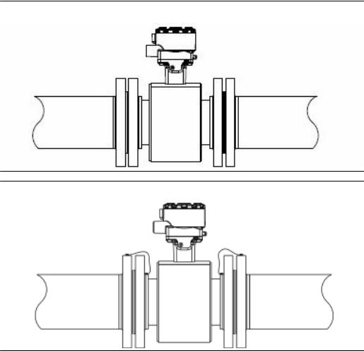
Figure 2-1: 8782 transmitter
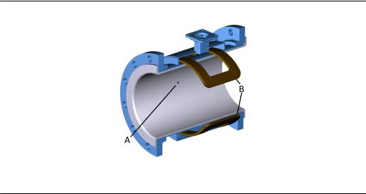
Figure 2-2: MS sensor
The flow sensor contains two magnetic coils located on opposite sides of the sensor. Two electrodes, located perpendicular to the coils and opposite each other, make contact with the liquid. The transmitter energizes the coils and creates a magnetic field. A conductive liquid moving through the magnetic field generates an induced voltage at the electrodes. This voltage is proportional to the flow velocity. The transmitter converts the voltage detected by the electrodes into a flow reading. A cross-sectional view is show in Figure 2-3.
Reference Manual |
11 |
Introduction |
Reference Manual |
November 2019 |
00809-0100-8782 |
Figure 2-3: Sensor cross section
A.Electrode
B.Coils
2.2Product recycling/disposal
Recycling of equipment and packaging should be taken into consideration and disposed of in accordance with local and national legislation/regulations.
12 |
Rosemount® 8782 Slurry Magnetic Flow Meter Transmitter with HART Protocol |

Reference Manual |
Sensor Installation |
00809-0100-8782 |
November 2019 |
3 Sensor Installation
This chapter provides instructions for handling and installing the flow sensor with a remotely mounted transmitter.
Related information
Remote Transmitter Installation
3.1Handling and Lifting Safety
CAUTION
To reduce the risk of personal injury or damage to equipment, follow all lifting and handling instructions.
•Handle all parts carefully to prevent damage. Whenever possible, transport the system to the installation site in the original shipping container.
•PTFE-lined sensors are shipped with end covers that protect flange sealing surfaces from both mechanical damage and normal unrestrained distortion. Remove the end covers just before installation.
•Keep the shipping plugs in the conduit ports until you are ready to connect and seal them. Appropriate care should be taken to prevent water ingress.
•The sensor should be supported by the pipeline. Pipe supports are recommended on both the inlet and outlet sides of the sensor pipeline. There should be no additional support attached to the sensor.
•Use proper PPE (Personal Protection Equipment) including safety glasses and safety shoes.
•Do not lift the meter by holding the electronics housing or junction box.
•The sensor liner is vulnerable to handling damage. Never place anything through the sensor for the purpose of lifting or gaining leverage. Liner damage can render the sensor useless.
•Do not drop the device from any height.
Reference Manual |
13 |

Sensor Installation |
Reference Manual |
November 2019 |
00809-0100-8782 |
3.1.1Lifting lugs
 CAUTION
If provided, use the lifting lugs on each flange to handle the flow meter when it is transported and lowered into place at the installation site. If lifting lugs are not provided, the flow meter must be supported with a lifting sling on each side of the housing.
•Standard pressure 3 inch through 36 inch flanged magnetic flowmeters come with lifting lugs.
•High pressure (above 600#) 3 inch through 24 inch flanged magnetic flow meters come with lifting lugs.
Figure 3-1: Example lifting without and with lifting lugs
A.Without lifting lugs
B.With lifting lugs
3.2Location and Position
3.2.1Environmental considerations
To ensure maximum transmitter life, avoid extreme temperatures and excessive vibration. Typical problem areas include the following:
•Tropical/desert installations in direct sunlight
•Outdoor installations in arctic climates
3.2.2Upstream and downstream piping
To ensure specified accuracy over widely varying process conditions, it is recommended to install the sensor with a minimum of five straight pipe diameters upstream and two pipe diameters downstream from the electrode plane.
14 |
Rosemount® 8782 Slurry Magnetic Flow Meter Transmitter with HART Protocol |
Reference Manual |
Sensor Installation |
00809-0100-8782 |
November 2019 |
Figure 3-2: Upstream and downstream straight pipe diameters
A |
B |
C 
A.Five pipe diameters (upstream)
B.Two pipe diameters (downstream)
C.Flow direction
Installations with reduced upstream and downstream straight runs are possible. In reduced straight run installations, the meter may not meet accuracy specifications. Reported flow rates will still be highly repeatable.
3.2.3Flow direction
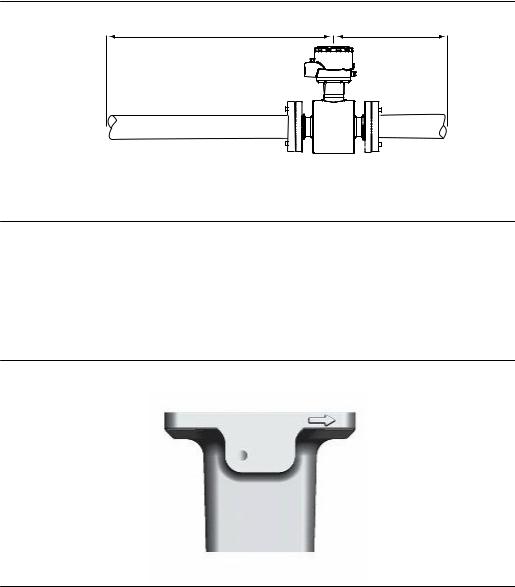
The sensor should be mounted so that the arrow points in the direction of flow.
Figure 3-3: Flow direction arrow
3.2.4Sensor piping location and orientation
The sensor should be installed in a location that ensures it remains full during operation. Depending on where it is installed, orientation must also be considered.
•Vertical installation with upward process fluid flow keeps the cross-sectional area full, regardless of flow rate.
•Horizontal installation should be restricted to low piping sections that are normally full.
Reference Manual |
15 |

Sensor Installation |
Reference Manual |
November 2019 |
00809-0100-8782 |
Figure 3-4: Sensor orientation
A.Flow direction
3.2.5Electrode orientation
The electrodes in the sensor are properly oriented when the two measurement electrodes are in the 3 and 9 o’clock positions or within 45 degrees from the horizontal, as shown on the left side of Figure 3-5. Avoid any mounting orientation that positions the top of the sensor at 90 degrees from the vertical position as shown on the right of Figure 3-5.
Figure 3-5: Electrode orientation
A
B
A.Correct orientation
B.Incorrect orientation
16 |
Rosemount® 8782 Slurry Magnetic Flow Meter Transmitter with HART Protocol |
Reference Manual |
Sensor Installation |
00809-0100-8782 |
November 2019 |
The sensor may require a specific orientation to comply with Hazardous Area T-code rating. Refer to the appropriate reference manual for any potential restrictions.
3.3Sensor Installation
3.3.1Flanged sensors
Gaskets
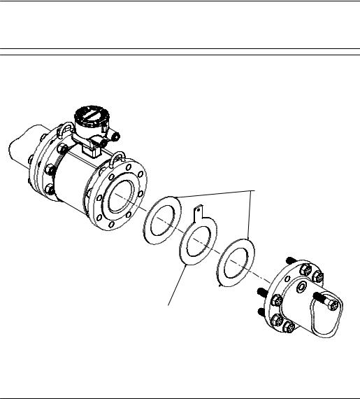
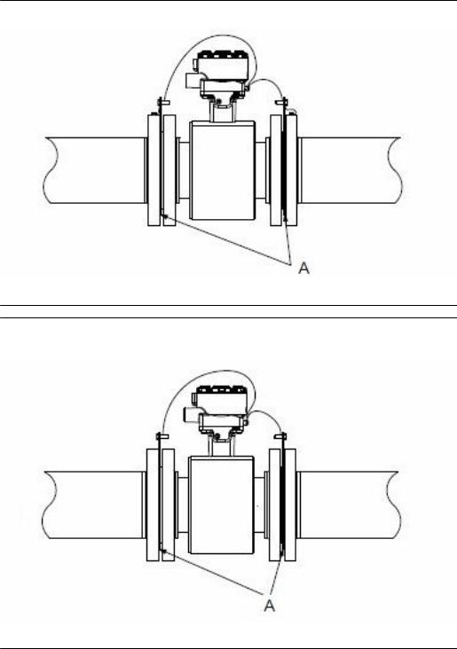
The sensor requires a gasket at each process connection. The gasket material must be compatible with the process fluid and operating conditions. Gaskets are required on each side of a grounding ring (see Figure 3-6). All other applications (including sensors with lining protectors or a grounding electrode) require only one gasket on each process connection.
Note
Metallic or spiral-wound gaskets should not be used as they will damage the liner face of the sensor. If spiral wound or metallic gaskets are required for the application, lining protectors must be used.
Figure 3-6: Gasket placement for flanged sensors
B
A
A.Grounding ring and gasket (optional)
B.Customer-supplied gasket
Reference Manual |
17 |

Sensor Installation |
Reference Manual |
November 2019 |
00809-0100-8782 |
Bolts
Note
Do not bolt one side at a time. Tighten both sides simultaneously. Example:
1.Snug upstream
2.Snug downstream
3.Tighten upstream
4.Tighten downstream
Do not snug and tighten the upstream side and then snug and tighten the downstream side. Failure to alternate between the upstream and downstream flanges when tightening bolts may result in liner damage.
Suggested torque values by sensor line size and liner type are listed in Table 3-2 for ASME B16.5 flanges and Table 3-3 or Table 3-4 for EN flanges. Consult the factory if the flange rating of the sensor is not listed. Tighten flange bolts on the upstream side of the sensor in the incremental sequence shown in Figure 3-7 to 20% of the suggested torque values. Repeat the process on the downstream side of the sensor. For sensors with greater or fewer flange bolts, tighten the bolts in a similar crosswise sequence. Repeat this entire tightening sequence at 40%, 60%, 80%, and 100% of the suggested torque values.
If leakage occurs at the suggested torque values, the bolts can be tightened in additional 10% increments until the joint stops leaking, or until the measured torque value reaches the maximum torque value of the bolts. Practical consideration for the integrity of the liner often leads to distinct torque values to stop leakage due to the unique combinations of flanges, bolts, gaskets, and sensor liner material.
Check for leaks at the flanges after tightening the bolts. Failure to use the correct tightening methods can result in severe damage. While under pressure, sensor materials may deform over time and require a second tightening 24 hours after the initial installation.
Figure 3-7: Flange bolt torquing sequence
8 1
 4 5
4 5
 6 3
6 3 2 7
2 7
Prior to installation, identify the lining material of the flow sensor to ensure the suggested torque values are applied.
18 |
Rosemount® 8782 Slurry Magnetic Flow Meter Transmitter with HART Protocol |
Reference Manual |
|
|
|
Sensor Installation |
||
00809-0100-8782 |
|
|
|
|
November 2019 |
|
Table 3-1: Lining material |
|
|
|
|
|
|
|
|
|
|
|
|
|
Fluoropolymer liners |
|
Other liners |
|
|
|
|
|
|
|
|
|
|
|
T - PTFE |
|
|
P - Polyurethane |
|
|
|
|
|
|
|
|
|
|
K - PFA+ |
|
|
N - Neoprene |
|
|
|
|
|
|
|
|
|
|
|
|
|
L - Linatex (Natural Rubber) |
|
|
|
|
|
|
|
|
|
|
|
|
|
D - Adiprene |
|
|
|
|
|
|
|
|
|
|
Table 3-2: Suggested flange bolt torque values for Rosemount MS (ASME) sensors |
|
|
||||
|
|
|
|
|
|
|
Size |
Line size |
Fluoropolymer liners |
Other liners |
|
|
|
code |
|
|
|
|
|
|
|
Class 150 (lb ft) |
Class 300 (lb ft) |
Class 150 (lb ft) |
|
Class 300 (pound |
|
|
|
|
||||
|
|
|
|
|
|
feet) |
|
|
|
|
|
|
|
030 |
3 inch (80 mm) |
34 |
35 |
23 |
|
23 |
|
|
|
|
|
|
|
040 |
4 inch (100 mm) |
26 |
50 |
17 |
|
32 |
|
|
|
|
|
|
|
060 |
6 inch (150 mm) |
45 |
50 |
30 |
|
37 |
|
|
|
|
|
|
|
080 |
8 inch (200 mm) |
60 |
82 |
42 |
|
55 |
|
|
|
|
|
|
|
100 |
10 inch (250 mm) |
55 |
80 |
40 |
|
70 |
|
|
|
|
|
|
|
120 |
12 inch (300 mm) |
65 |
125 |
55 |
|
105 |
|
|
|
|
|
|
|
140 |
14 inch (350 mm) |
85 |
110 |
70 |
|
95 |
|
|
|
|
|
|
|
160 |
16 inch (400 mm) |
85 |
160 |
65 |
|
140 |
|
|
|
|
|
|
|
180 |
18 inch (450 mm) |
120 |
170 |
95 |
|
150 |
|
|
|
|
|
|
|
200 |
20 inch (500 mm) |
110 |
175 |
90 |
|
150 |
|
|
|
|
|
|
|
240 |
24 inch (600 mm) |
165 |
280 |
140 |
|
250 |
|
|
|
|
|
|
|
300 |
30 inch (750 mm) |
195 |
415 |
165 |
|
375 |
|
|
|
|
|
|
|
360 |
36 inch (900 mm) |
280 |
575 |
245 |
|
525 |
|
|
|
|
|
|
|
Table 3-3: Suggested flange bolt torque values for Rosemount MS sensors with fluoropolymer liners (EN 1092-1)
Size |
Line size |
Fluoropolymer liners (in Newton-meters) |
|
||
code |
|
|
|
|
|
|
PN 10 |
PN 16 |
PN 25 |
PN 40 |
|
|
|
||||
|
|
|
|
|
|
030 |
3 inch (80 mm) |
N/A |
N/A |
N/A |
50 |
|
|
|
|
|
|
040 |
4 inch (100 mm) |
N/A |
50 |
N/A |
70 |
|
|
|
|
|
|
060 |
6 inch (150mm) |
N/A |
90 |
N/A |
130 |
|
|
|
|
|
|
Reference Manual |
19 |

Sensor Installation |
Reference Manual |
November 2019 |
00809-0100-8782 |
Table 3-3: Suggested flange bolt torque values for Rosemount MS sensors with fluoropolymer liners (EN 1092-1) (continued)
Size |
Line size |
Fluoropolymer liners (in Newton-meters) |
|
||
code |
|
|
|
|
|
|
PN 10 |
PN 16 |
PN 25 |
PN 40 |
|
|
|
||||
|
|
|
|
|
|
080 |
8 inch (200 mm) |
130 |
90 |
130 |
170 |
|
|
|
|
|
|
100 |
10 inch (250 mm) |
100 |
130 |
190 |
250 |
|
|
|
|
|
|
120 |
12 inch (300 mm) |
120 |
170 |
190 |
270 |
|
|
|
|
|
|
140 |
14 inch (350 mm) |
160 |
220 |
320 |
410 |
|
|
|
|
|
|
160 |
16 inch (400 mm) |
220 |
280 |
410 |
610 |
|
|
|
|
|
|
180 |
18 inch (450 mm) |
190 |
340 |
330 |
420 |
|
|
|
|
|
|
200 |
20 inch (500 mm) |
230 |
380 |
440 |
520 |
|
|
|
|
|
|
240 |
24 inch (600 mm) |
290 |
570 |
590 |
850 |
|
|
|
|
|
|
Table 3-4: Suggested flange bolt torque values for Rosemount MS sensors with non-fluoropolymer liners (EN 1092-1)
Size |
Line size |
Non-fluoropolymer liners (in Newton-meters) |
|
||
code |
|
|
|
|
|
|
PN 10 |
PN 16 |
PN 25 |
PN 40 |
|
|
|
||||
|
|
|
|
|
|
030 |
3 inch (80 mm) |
N/A |
N/A |
N/A |
30 |
|
|
|
|
|
|
040 |
4 inch (100 mm) |
N/A |
40 |
N/A |
50 |
|
|
|
|
|
|
060 |
6 inch (150mm) |
N/A |
60 |
N/A |
90 |
|
|
|
|
|
|
080 |
8 inch (200 mm) |
90 |
60 |
90 |
110 |
|
|
|
|
|
|
100 |
10 inch (250 mm) |
70 |
80 |
130 |
170 |
|
|
|
|
|
|
120 |
12 inch (300 mm) |
80 |
110 |
130 |
180 |
|
|
|
|
|
|
140 |
14 inch (350 mm) |
110 |
150 |
210 |
288 |
|
|
|
|
|
|
160 |
16 inch (400 mm) |
150 |
190 |
280 |
410 |
|
|
|
|
|
|
180 |
18 inch (450 mm) |
130 |
230 |
220 |
280 |
|
|
|
|
|
|
200 |
20 inch (500 mm) |
150 |
260 |
300 |
350 |
|
|
|
|
|
|
240 |
24 inch (600 mm) |
200 |
380 |
390 |
560 |
|
|
|
|
|
|
3.4Process reference connection
The figures shown in this section illustrate best practice installations for process reference connections only. For installations in conductive, unlined pipe it may be acceptable to use one ground ring or one lining protector to establish a process reference connection. Earth safety ground is also required as part of this installation, but is not shown in the figures.
Follow national, local, and plant electrical codes for safety ground.
Use Table 3-5 to determine which process reference option to follow for proper installation.
20 |
Rosemount® 8782 Slurry Magnetic Flow Meter Transmitter with HART Protocol |
Reference Manual |
|
|
|
Sensor Installation |
||
00809-0100-8782 |
|
|
|
|
|
November 2019 |
|
Table 3-5: Process reference options |
|
|
|
||
|
|
|
|
|
|
|
|
Type of pipe |
Grounding |
Grounding rings |
Reference |
|
Lining protectors |
|
|
straps |
|
electrode |
|
|
|
|
|
|
|
|
|
|
Conductive |
See Figure 3-8 |
See Figure 3-9 |
See Figure 3-11 |
|
See Figure 3-9 |
|
unlined pipe |
|
|
|
|
|
|
|
|
|
|
|
|
|
Conductive lined |
Insufficient |
See Figure 3-9 |
See Figure 3-8 |
|
See Figure 3-9 |
|
pipe |
grounding |
|
|
|
|
|
|
|
|
|
|
|
|
Non-conductive |
Insufficient |
See Figure 3-10 |
Not |
|
See Figure 3-10 |
|
pipe |
grounding |
|
recommended |
|
|
|
|
|
|
|
|
|
Note
For line sizes 10-inch and larger the ground strap may come attached to the sensor body near the flange. See Figure 3-12.
Figure 3-8: Grounding straps in conductive unlined pipe or reference electrode in lined pipe
Reference Manual |
21 |
Sensor Installation |
Reference Manual |
November 2019 |
00809-0100-8782 |
Figure 3-9: Grounding with grounding rings or lining protectors in conductive pipe
A. Grounding rings or lining protectors
Figure 3-10: Grounding with grounding rings or lining protectors in non-conductive pipe
A. Grounding rings or lining protectors
22 |
Rosemount® 8782 Slurry Magnetic Flow Meter Transmitter with HART Protocol |
Reference Manual |
Sensor Installation |
00809-0100-8782 |
November 2019 |
Figure 3-11: Grounding with reference electrode in conductive unlined pipe
Figure 3-12: Grounding for line sizes 10-in. and larger
Reference Manual |
23 |
Sensor Installation |
Reference Manual |
November 2019 |
00809-0100-8782 |
24 |
Rosemount® 8782 Slurry Magnetic Flow Meter Transmitter with HART Protocol |

Reference Manual |
Remote Transmitter Installation |
00809-0100-8782 |
November 2019 |
4 Remote Transmitter Installation
This chapter provides instructions for installing and wiring a remotely mounted transmitter.
Related information
Sensor Installation
4.1Pre-installation
Before installing the transmitter, there are several pre-installation steps that should be completed to make the installation process easier:
•Identify options and configurations that apply to your application
•Set the hardware switches if necessary
•Consider mechanical, electrical, and environmental requirements
Note
Refer to Product Specifications for more detailed requirements.
Identify options and configurations
The typical transmitter installation includes a device power connection, a 4-20mA output connection, and sensor coil and electrode connections. Other applications may require one or more of the following configurations or options:
•Pulse output
•Discrete input/discrete output
•HART multidrop configuration
The transmitter may have up to four user-selectable hardware switches. These switches set the alarm mode, internal/external analog power, internal/external pulse power, and transmitter security. The standard configuration for these switches when shipped from the factory is as follows:
Table 4-1: Hardware switch default settings
Setting |
Factory configuration |
|
|
Alarm mode |
High |
|
|
Internal/external analog power |
Internal |
|
|
Internal/external pulse power |
External |
|
|
Transmitter security |
Off |
|
|
The analog power switch and pulse power switches are not available when ordered with intrinsically safe output, ordering code B.
In most cases, it is not necessary to change the setting of the hardware switches. If the switch settings need to be changed, refer to Hardware switches.
Reference Manual |
25 |
Remote Transmitter Installation |
Reference Manual |
November 2019 |
00809-0100-8782 |
Be sure to identify any additional options and configurations that apply to the installation. Keep a list of these options for consideration during the installation and configuration procedures.
Mechanical considerations
The mounting site for the transmitter should provide enough room for secure mounting, easy access to conduit entries, full opening of the transmitter covers, and easy readability of the Local Operator Interface (LOI) screen (if equipped).
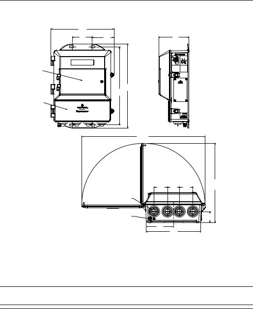
Figure 4-1: Rosemount 8782 Dimensional Drawing
9.0 |
|
(229) |
|
2.8 |
3.1 |
(71) |
(79) |
C |
|
12.0
11.2 (306)
(283)
D
A
B
3.5 |
(89) |
17.7 |
|
|
|
(449) |
|
|
|
|
|
|
11.4 |
1.9 |
1.7 |
1.9 |
(289) |
(49) |
(43) |
(49) |
|
|
|
|
1.6 |
|
|
|
(40) |
3.9 |
|
|
|
(99) |
7.8 |
|
|
|
(198) |
|
|
A.Conduit entry, ½–14 NPT (4 places)
B.Ground lug
C.LOI keypad cover
D.Lower cover opens for electrical connections
Note
Dimensions are in inches (Millimeters)
26 |
Rosemount® 8782 Slurry Magnetic Flow Meter Transmitter with HART Protocol |

Reference Manual |
Remote Transmitter Installation |
00809-0100-8782 |
November 2019 |
Electrical considerations
Before making any electrical connections to the transmitter, consider national, local, and plant electrical installation requirements. Be sure to have the proper power supply, conduit, and other accessories necessary to comply with these standards.
The transmitter requires external power. Ensure access to a suitable power source.
Table 4-2: Electrical Data
Electrical data
Power input |
AC power: |
|
|||||
|
90–250 VAC ( |
), 1.5A, 120 VA |
|||||
|
|
||||||
|
Standard DC power: |
||||||
|
12–42 VDC ( |
|
|
|
|
|
), 8.6 A, 120 W |
|
|
|
|
|
|
||
|
|
|
|
|
|
||
|
|
||||||
Pulsed circuit |
Internally powered (Active): Outputs up to |
||||||
|
12 VDC, 12.1 mA, 73 mW |
||||||
|
Externally powered (Passive): Input up to |
||||||
|
28 VDC, 100 mA, 1 W |
||||||
|
|
||||||
4-20mA output circuit |
Internally Powered (Active): Outputs up to |
||||||
|
25 mA, 24 VDC, 600 mW |
||||||
|
Externally Powered (Passive): Input up to 25 mA, |
||||||
|
30 VDC, 750 mW |
||||||
|
|
|
|||||
Um |
250 V |
|
|||||
|
|
||||||
Coil excitation output |
2.0 A, 85 V max, 80 W max |
||||||
|
|
|
|
|
|
|
|
Environmental considerations
Remote mounted transmitters may be installed in the control room to protect the electronics from the harsh environment and to provide easy access for configuration or service.
Table 4-3: Transmitter housing environmental ratings
Type |
Rating |
|
|
Ingress protection |
IP66, IP69 |
|
|
NEMA |
4X |
|
|
Pollution Degree |
2 |
|
|
Maximum altitude rating |
• 13,123 ft (4000 m) at rated input power |
|
voltage (90–250 VAC) |
|
• 16,404 ft (5000 m) at maximum input |
|
power voltage of 150 VAC |
|
|
Note
For complete environmental and other specifications, see Product Specifications.
Reference Manual |
27 |
Remote Transmitter Installation |
Reference Manual |
November 2019 |
00809-0100-8782 |
4.2Transmitter symbols
Caution symbol — check product documentation for details
Protective conductor (grounding) terminal
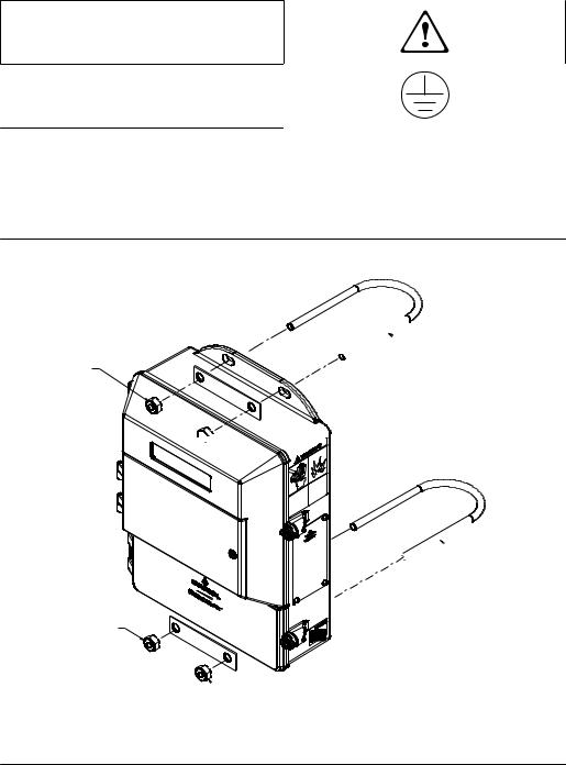
4.3Mounting
Wall mount transmitters are shipped with mounting hardware for use on a 2 inch (50 mm) pipe or flat surface.
Figure 4-2: Mounting bracket


 A
A
B


 B
B

 A
A
B
 B
B
A.U-bolt
B.Fasteners
4.3.1Pipe mounting
1.Assemble the hardware and transmitter housing on the pole as shown in Figure 4-2.
2.Tighten the nuts to ensure a snug fit.
28 |
Rosemount® 8782 Slurry Magnetic Flow Meter Transmitter with HART Protocol |
Reference Manual |
Remote Transmitter Installation |
00809-0100-8782 |
November 2019 |
4.3.2Surface mounting
Attach the transmitter to the mounting location using customer supplied mounting screws. The installation of the transmitter shall be rated for four (4) times the weight of the transmitter or 44lbs (20kgs).
4.4Wiring
4.4.1Conduit entries and connections
Transmitter conduit entries ports are ½"-14NPT as standard, M20 conduit connections will use an adapter. Conduit connections should be made in accordance with national, local, and plant electrical codes. Unused conduit entries should be sealed with the appropriate certified plugs. The plastic shipping plugs do not provide ingress protection.
4.4.2Conduit requirements
•For installations with an intrinsically safe electrode circuit, a separate conduit for the coil cable and the electrode cable may be required. Refer to Product Certifications.Refer to the product reference manual.
•For installations with non-intrinsically safe electrode circuit, a single dedicated conduit run for the coil drive and electrode cable between the sensor and the remote transmitter may be acceptable. Removal of the barriers for intrinsic safety isolation is permitted for non-intrinsically safe electrode installations.
•Bundled cables from other equipment in a single conduit are likely to create interference and noise in the system. See Figure 4-3.
•Electrode cables should not be run together in the same cable tray with power cables.
•Output cables should not be run together with power cables.
•Select conduit size appropriate to feed cables through to the flowmeter.
Reference Manual |
29 |
Remote Transmitter Installation |
Reference Manual |
November 2019 |
00809-0100-8782 |
Figure 4-3: Best practice conduit preparation
A |
C D E |
A |
|
||
|
B |
|
A |
A.Safety ground
B.Power
C.Coil
D.Output
E.Electrode
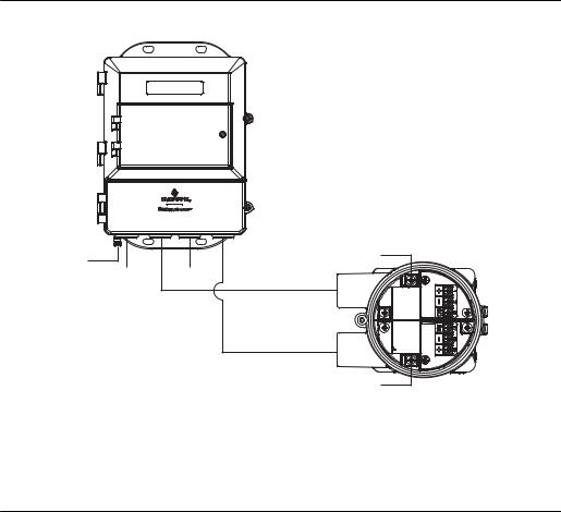
4.4.3Sensor to transmitter wiring
Remote cable kits can be ordered directly using the kit numbers shown in Table 4-4 and Table 4-5. Equivalent Alpha cable part numbers are also provided as an alternative. To order cable, specify length as quantity desired. Equal length of component cables is required.
Examples:
•25 feet = Qty (25) 08732-0065-0001
•25 meters = Qty (25) 08732-0065-0002
Table 4-4: Component cable kits - standard temperature (-20°C to 75°C)
Cable kit # |
|
Description |
Individual cable |
Alpha p/n |
|
|
|
|
|
08732-0065-0001 |
(feet) |
Kit, component cables, Std temp |
Coil |
2442C |
|
|
(includes Coil and Electrode) |
Electrode |
2413C |
|
|
|
||
|
|
|
|
|
08732-0065-0002 |
(meters) |
Kit, component cables, Std temp |
Coil |
2442C |
|
|
(includes Coil and Electrode) |
Electrode |
2413C |
|
|
|
||
|
|
|
|
|
30 |
Rosemount® 8782 Slurry Magnetic Flow Meter Transmitter with HART Protocol |
Loading...