


 Loading...
Quick Start Guide
00825-0300-4750, Rev CA
March 2016
Rosemount™ 8750W Magnetic Flowmeter System
for Utility, Water, and Wastewater Applications

Quick Start Guide |
March 2016 |
|
|
NOTICE
This document provides basic installation guidelines for the Rosemount 8750W Magnetic Flowmeter Platform. For comprehensive instructions for detailed configuration, diagnostics, maintenance, service, installation, or troubleshooting refer to the Rosemount 8750W Reference Manual (document number 00809-0300-4750). The manual and Quick Start Guide are also available electronically on EmersonProcess.com/Rosemount.
Failure to follow these installation guidelines could result in death or serious injury.
Installation and servicing instructions are for use by qualified personnel only. Do not perform any servicing other than that contained in the operating instructions, unless qualified.
Verify the installation is done safely and is consistent with the operating environment.
Ensure the device certification and installation techniques are suitable for the installation environment.
Explosion hazard. Do not disconnect equipment when a flammable or combustible atmosphere is present.
To prevent ignition of flammable or combustible atmospheres, disconnect power before servicing circuits.
Do not connect a Rosemount 8750W Transmitter to a non-Rosemount sensor that is located in an explosive atmosphere.
Follow national, local, and plant standards to properly earth ground the transmitter and sensor. The earth ground must be separate from the process reference ground.
Rosemount Magnetic Flowmeters ordered with non-standard paint options or non-metallic labels may be subject to electrostatic discharge. To avoid electrostatic charge build-up, do not rub the flowmeter with a dry cloth or clean with solvents.
NOTICE
The sensor liner is vulnerable to handling damage. Never place anything through the sensor for the purpose of lifting or gaining leverage. Liner damage may render the sensor inoperable.
Metallic or spiral-wound gaskets should not be used as they will damage the liner face of the sensor. If frequent removal is anticipated, take precautions to protect the liner ends. Short spool pieces attached to the sensor ends are often used for protection.
Correct flange bolt tightening is crucial for proper sensor operation and life. All bolts must be tightened in the proper sequence to the specified torque specifications. Failure to observe these instructions could result in severe damage to the sensor lining and possible sensor replacement.
In cases where high voltage/high current are present near the meter installation, ensure proper protection methods are followed to prevent stray voltage/current from passing through the meter. Failure to adequately protect the meter could result in damage to the transmitter and lead to meter failure.
Completely remove all electrical connections from both sensor and transmitter prior to welding on the pipe. For maximum protection of the sensor, consider removing it from the pipeline.
Contents
Transmitter installation . . . . . . . . . . . . . . . . |
. 3 |
Wiring the transmitter . . . . . . . . . . . . . . . . . . . . . . |
18 |
Handling and lifting . . . . . . . . . . . . . . . . . . . . |
8 |
Basic configuration . . . . . . . . . . . . . . . . . . . . . . . . . |
31 |
Mounting . . . . . . . . . . . . . . . . . . . . . . . . . . . . . |
9 |
Product Certifications . . . . . . . . . . . . . . . . . . . . . . |
36 |
Sensor installation . . . . . . . . . . . . . . . . . . . . . |
11 |
Installation and wiring drawings . . . . . . . . . . . . . . |
48 |
Process reference connection . . . . . . . . . . . |
16 |
|
|
2

March 2016 |
Quick Start Guide |
1.0 Transmitter installation
Installation of the Rosemount Magnetic Flowmeter Transmitter includes both detailed mechanical and electrical installation procedures.
Before installing the Rosemount 8750W, there are several pre-installation steps that should be completed to make the installation process easier:
Identify the options and configurations that apply to your application.
Set the hardware switches if necessary.
Consider mechanical, electrical, and environmental requirements.
1.1Identify options and configurations
The typical installation of the Rosemount 8750W includes a device power connection, a 4–20mA output connection, and sensor coil and electrode connections. Other applications may require one or more of the following configurations or options:
Pulse output
Discrete input/discrete output
HART® Multidrop Configuration
Hardware switches
The Rosemount 8750W electronics stack is equipped with user-selectable hardware switches. These switches set the Alarm mode, Internal/external analog power, Internal/external pulse power(1), and Transmitter security. The standard configuration for these switches when shipped from the factory are as follows:
Table 1. Standard Switch Configuration
Setting |
Standard switch configuration |
|
|
Alarm mode |
High |
Internal/external analog power |
Internal |
Internal/external pulse power(1) |
External |
Transmitter security |
Off |
|
|
In most cases, it will not be necessary to change the setting of the hardware switches. If the switch settings need to be changed, follow the steps outlined in the “Changing hardware switch settings” section of the Rosemount 8750W Reference Manual.
NOTICE
To prevent switch damage, use a non-metallic tool to move switch positions.
Be sure to identify any additional options and configurations that apply to the installation. Keep a list of these options for consideration during the installation and configuration procedures.
1. Rosemount 8750W Field Mount Transmitter only.
3

Quick Start Guide |
March 2016 |
|
|
1.2 Mechanical considerations
The mounting site for the Rosemount 8750W should provide enough room for secure mounting, easy access to conduit entries, full opening of the transmitter covers, and easy readability of the LOI screen if equipped.
For remote field mount transmitter installations, a mounting bracket is provided for use on a 2-in. pipe or a flat surface (see Figure 1).
NOTICE
If the transmitter is mounted separately from the sensor, it may not be subject to limitations that might apply to the sensor.
Rotate integral mount transmitter housing
The transmitter housing can be rotated on the sensor in 90° increments by removing the four mounting screws on the bottom of the housing. Do not rotate the housing more than 180° in any one direction. Prior to tightening, be sure the mating surfaces are clean, the O-ring is seated in the groove, and there is no gap between the housing and the sensor.
4

March 2016 |
Quick Start Guide |
|
|
|
|
|
|
|
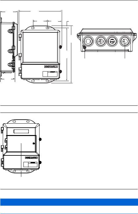
Figure 1. Rosemount 8750W Field Mount Transmitter
|
7.49 |
|
|
|
(189,8) |
|
|
|
6.48 |
|
|
|
(164,6) |
|
|
|
1.94 |
|
A |
|
(49,3) |
|
B |
5.00 |
3.00 |
|
D |
(127,0) |
(76,2) |
|
|
|
8.86 |
||
|
|
|
|
|
|
|
(225,1) |
10.29 |
|
|
|
(261,3) |
|
|
|
2.81 |
|
2.22 |
3.07 |
(71,4) |
|
||
|
(78,0) |
||
|
(56,4) |
||
|
|
||
|
|
|
|
C |
|
1.80 |
A |
|
|
(45,7) |
|
|
5.00 |
|
|
|
(127,0) |
|
|
|
10.18 |
|
|
|
(258,6) |
|
|
5.77
(146,4)
7.64 |
(194,0) |
A.1/2-in.–14 NPT conduit entry
B.LOI cover
C.2-in. pipe bracket
D.Ground lug
Dimensions are in inches (millimeters).
Figure 2. Rosemount 8750W Integral Field Mount Transmitter
5.82
(147,8)
5
Quick Start Guide |
March 2016 |
|
|
Figure 3. Rosemount 8750W Wall Mount Transmitter with Standard Cover
4.31 |
9.01 |
|
|
|
(229) |
|
|
|
|
(109) |
|
|
|
|
|
|
|
|
|
|
2.81 |
3.11 |
0.44 |
|
|
(71) |
(79) |
|
|
|
|
|
12.02 |
|
|
|
|
(305) |
|
|
|
|
11.15 |
|
|
|
|
(283) |
|
|
|
|
A |
B |
2.96 |
|
|
|
|
(75) |
|
|
|
|
A.Ground lug
B.1/2-in.–14 NPT or M20 conduit entry
Dimensions in inches (millimeters).
Figure 4. Rosemount 8750W Wall Mount Transmitter with LOI Cover
A |
A. LOI keypad cover
NOTICE
Default conduit entries are 1/2-in. NPT. If an alternate thread connection is required, thread adapters must be used.
6

March 2016 |
Quick Start Guide |
|
|
1.3 Electrical considerations
Before making any electrical connections to the Rosemount 8750W, consider national, local and plant electrical installation requirements. Be sure to have the proper power supply, conduit, and other accessories necessary to comply with these standards.
Both remotely and integrally mounted transmitters require external power so there must be access to a suitable power source.
Table 2. Electrical Data
Field mount transmitter
Power input |
90–250VAC, 0.45A, 40VA |
|
12–42VDC, 1.2A, 15W |
||
|
||
|
|
|
Pulsed circuit |
Internally powered (Active): Outputs up to 12VDC, 12.1mA, 73mW |
|
Externally powered (Passive): Input up to 28VDC, 100mA, 1W |
||
|
||
|
|
|
4-20mA output circuit |
Internally Powered (Active): Outputs up to 25mA, 24VDC, 600mW |
|
Externally Powered (Passive): Input up to 25mA, 30VDC, 750mW |
||
|
||
|
|
|
Coil excitation output |
500mA, 40V max, 9W max |
|
|
|
|
Wall mount transmitter |
|
|
|
|
|
Power input |
90–250VAC, 0.28A, 40VA |
|
12–42VDC, 1A, 15W |
||
|
||
|
|
|
Pulsed circuit |
Externally powered (Passive): 5–24VDC, up to 2W |
|
|
|
|
4-20mA output circuit |
Internally powered (Active): Outputs up to 25mA, 30VDC |
|
Externally powered (Passive): Input up to 25mA, 10–30VDC |
||
|
||
|
|
|
Coil excitation output |
500mA, 40V max, 9W max |
|
|
|
|
Sensor(1) |
|
|
Coil excitation input |
500mA, 40V max, 20W max |
|
|
|
|
Electrode circuit |
5V, 200uA, 1mW |
|
|
|
1.Provided by the transmitter.
1.4Environmental considerations
To ensure maximum transmitter life, avoid extreme temperatures and excessive vibration. Typical problem areas:
high-vibration lines with integrally mounted transmitters
tropical/desert installations in direct sunlight
outdoor installations in arctic climates
Remote-mounted transmitters may be installed in the control room to protect the electronics from the harsh environment and to provide easy access for configuration or service.
7
Quick Start Guide |
March 2016 |
|
|
2.0Handling and lifting
Handle all parts carefully to prevent damage. Whenever possible, transport the system to the installation site in the original shipping container.
PTFE-lined sensors are shipped with end covers that protect it from both mechanical damage and normal unrestrained distortion. Remove the end covers just before installation.
Keep the shipping plugs in the conduit connections until you are ready to connect and seal them.
The sensor should be supported by the pipeline. Pipe supports are recommended on both the inlet and outlet sides of the sensor pipeline. There should be no additional support attached to the sensor.
Additional safety recommendations for mechanical handling:
-Use proper PPE (Personal Protection Equipment should include safety glasses and steel toed shoes).
-Do not drop the device from any height.
Do not lift the meter by holding the electronics housing or junction box.The sensor liner is vulnerable to handling damage. Never place anything through the sensor for the purpose of lifting or gaining leverage. Liner damage can render the sensor useless.
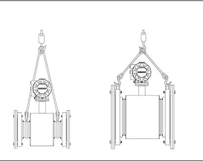
If provided, use the lifting lugs on each flange to handle the Magnetic Flowmeter when it is transported and lowered into place at the installation site. If lifting lugs are not provided, the Magnetic Flowmeter must be supported with a lifting sling on each side of the housing.
Flanged sensors 3-in. through 48-in. come with lifting lugs.
Wafer sensors do not come with lifting lugs.
Figure 5. Support for Handling and Lifting
Without lifting lugs |
With lifting lugs |
8
March 2016 |
Quick Start Guide |
3.0Mounting
3.1Upstream/downstream piping
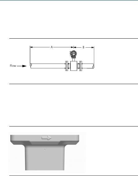
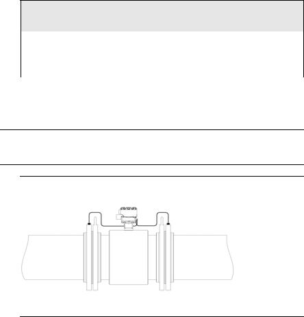
To ensure specified accuracy over widely varying process conditions, install the sensor with a minimum of five straight pipe diameters upstream and two pipe diameters downstream from the electrode plane (see Figure 6).
Figure 6. Upstream and Downstream Straight Pipe Diameters
A.Five pipe diameters
B.Two pipe diameters
Installations with reduced upstream and downstream straight runs are possible. In reduced straight run installations, the meter may not meet absolute accuracy specifications. Reported flow rates will still be highly repeatable.
3.2 Flow direction
The sensor should be mounted so the arrow points in the direction of flow. See Figure 7.
Figure 7. Flow Direction Arrow
3.3 Sensor location
The sensor should be installed in a location that ensures it remains full during operation. Vertical installation with upward process fluid flow keeps the cross-sectional area full, regardless of flow rate. Horizontal installation should be restricted to low piping sections that are normally full.
9
Quick Start Guide |
March 2016 |
|
|
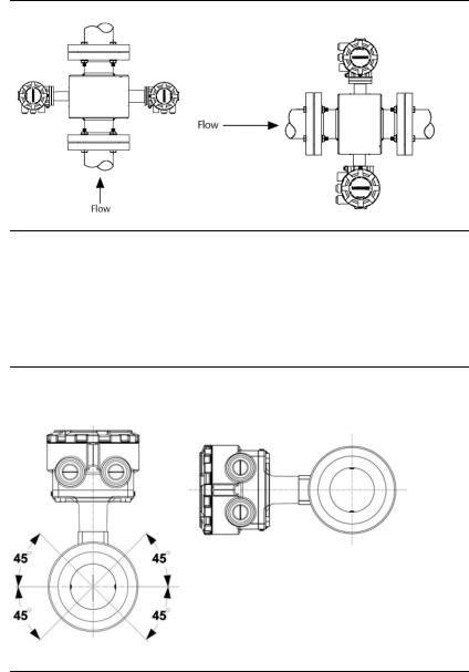
Figure 8. Sensor Orientation
3.4 Electrode orientation
The electrodes in the sensor are properly oriented when the two measurement electrodes are in the 3 and 9 o’clock positions or within 45° from the horizontal, as shown on the left of Figure 9. Avoid any mounting orientation that positions the top of the sensor at 90° from the vertical position as shown on the right of Figure 9.
Figure 9. Mounting Position
Correct |
Incorrect |
10
March 2016 |
Quick Start Guide |
4.0Sensor installation
4.1Gaskets
The sensor requires a gasket ateach process connection. The gasketmaterial must be compatible with the processfluid and operating conditions. Gaskets are required on each side of a grounding ring (see Figure 10). All other applications (including sensors or a grounding electrode) require only one gasket on each process connection.
NOTICE
Metallic or spiral-wound gaskets should not be used as they will damage the liner face of the sensor.
Figure 10. Flanged Gasket Placement
A.Grounding ring and gasket (optional)
B.Customer-supplied gasket
11

Quick Start Guide |
March 2016 |
|
|
4.2 Flange bolts
Note
Do not bolt one side at a time. Tighten both sides simultaneously. Example:
1.Snug upstream.
2.Snug downstream.
3.Tighten upstream.
4.Tighten downstream.
Do not snug and tighten the upstream side and then snug and tighten the downstream side. Failure to alternate between the upstream and downstream flanges when tightening bolts may result in liner damage.
Suggested torque values by sensor line size and liner type are listed in Table 4 for ASME B16.5 flanges, Table 5 for EN flanges, and Table 6 and Table 7 for AWWA and EN flanges for line sizes 30-in. (750 mm) to 48-in. (1300 mm). Consult your local Emerson™ Process Management representative if the flange rating of the sensor is not listed. Tighten flange bolts on the upstream side of the sensor in the incremental sequence shown in Figure 11 to 20 percent of the suggested torque values. Repeat the process on the downstream side of the sensor. For sensors with more or less flange bolts, tighten the bolts in a similar crosswise sequence. Repeat this entire tightening sequence at 40, 60, 80, and 100% of the suggested torque values.
If leakage occurs at the suggested torque values, the bolts can be tightened in additional 10% increments until the joint stops leaking, or until the measured torque value reaches the maximum torque value of the bolts. Practical consideration for the integrity of the liner often leads the user to distinct torque values to stop leakage due to the unique combinations of flanges, bolts, gaskets, and sensor liner material.
Check for leaks at the flanges after tightening the bolts. Failure to use the correct tightening methods can result in severe damage. While under pressure, sensor materials may deform over time and require a second tightening 24 hours after the initial installation.
Figure 11. Flange Bolt Torquing Sequence
Prior to installation, identify the lining material of the flow sensor to ensure the suggested torque values are applied.
12

March 2016 |
|
Quick Start Guide |
|
|
|
|
|
|
Table 3. Lining Material |
||
|
|
|
|
|
Fluoropolymer liners |
Resilient liners |
|
|
|
|
|
|
T - PTFE |
P - Polyurethane |
|
|
N - Neoprene |
|
|
|
|
|
|
|
|
|
|
Table 4. Flange Bolt Torque and Load Specifications for 8750W (ASME)
Size |
|
Fluoropolymer liners |
Resilient liners |
|||
Line size |
|
|
|
|
||
code |
Class 150 |
Class 300 |
Class 150 |
Class 300 |
||
|
||||||
|
|
(pound-feet) |
(pound-feet) |
(pound-feet) |
(pound-feet) |
|
|
|
|
|
|
|
|
005 |
0.5-in. (15 mm) |
8 |
8 |
N/A |
N/A |
|
010 |
1-in. (25 mm) |
8 |
12 |
N/A |
N/A |
|
015 |
1.5-in. (40 mm) |
13 |
25 |
7 |
18 |
|
020 |
2-in. (50 mm) |
19 |
17 |
14 |
11 |
|
025 |
2.5-in. (65 mm) |
22 |
24 |
17 |
16 |
|
030 |
3-in. (80 mm) |
34 |
35 |
23 |
23 |
|
040 |
4-in. (100 mm) |
26 |
50 |
17 |
32 |
|
050 |
5-in. (125 mm) |
36 |
60 |
25 |
35 |
|
060 |
6-in. (150 mm) |
45 |
50 |
30 |
37 |
|
080 |
8-in. (200 mm) |
60 |
82 |
42 |
55 |
|
100 |
10-in. (250 mm) |
55 |
80 |
40 |
70 |
|
120 |
12-in. (300 mm) |
65 |
125 |
55 |
105 |
|
140 |
14-in. (350 mm) |
85 |
110 |
70 |
95 |
|
160 |
16-in. (400 mm) |
85 |
160 |
65 |
140 |
|
180 |
18-in. (450 mm) |
120 |
170 |
95 |
150 |
|
200 |
20-in. (500 mm) |
110 |
175 |
90 |
150 |
|
240 |
24-in. (600 mm) |
165 |
280 |
140 |
250 |
|
|
|
|
|
|
|
|
13
Quick Start Guide |
March 2016 |
|
|
Table 5. Flange Bolt Torque and Load Specifications for 8750W (EN 1092-1)
Size |
|
|
Fluoropolymer liners |
|
||
code |
Line size |
PN10 |
PN 16 |
PN 25 |
PN 40 |
|
|
||||||
|
|
(Newton-meter) |
(Newton-meter) |
(Newton-meter) |
(Newton-meter) |
|
005 |
0.5-in. (15 mm) |
N/A |
N/A |
N/A |
10 |
|
010 |
1-in. (25 mm) |
N/A |
N/A |
N/A |
20 |
|
015 |
1.5-in. (40 mm) |
N/A |
N/A |
N/A |
50 |
|
020 |
2-in. (50 mm) |
N/A |
N/A |
N/A |
60 |
|
025 |
2.5-in. (65 mm) |
N/A |
N/A |
N/A |
50 |
|
030 |
3-in. (80 mm) |
N/A |
N/A |
N/A |
50 |
|
040 |
4-in. (100 mm) |
N/A |
50 |
N/A |
70 |
|
050 |
5-in. (125 mm) |
N/A |
70 |
N/A |
100 |
|
060 |
6-in. (150mm) |
N/A |
90 |
N/A |
130 |
|
080 |
8-in. (200 mm) |
130 |
90 |
130 |
170 |
|
100 |
10-in. (250 mm) |
100 |
130 |
190 |
250 |
|
120 |
12-in. (300 mm) |
120 |
170 |
190 |
270 |
|
140 |
14-in. (350 mm) |
160 |
220 |
320 |
410 |
|
160 |
16-in. (400 mm) |
220 |
280 |
410 |
610 |
|
180 |
18-in. (450 mm) |
190 |
340 |
330 |
420 |
|
200 |
20-in. (500 mm) |
230 |
380 |
440 |
520 |
|
240 |
24-in. (600 mm) |
290 |
570 |
590 |
850 |
|
Size |
|
|
Resilient liners |
|
||
Line size |
|
|
|
|
||
code |
PN 10 |
PN 16 |
PN 25 |
PN 40 |
||
|
||||||
|
|
(Newton-meter) |
(Newton-meter) |
(Newton-meter) |
(Newton-meter) |
|
|
|
|
|
|
|
|
010 |
1-in. (25 mm) |
N/A |
N/A |
N/A |
20 |
|
015 |
1.5-in. (40 mm) |
N/A |
N/A |
N/A |
30 |
|
020 |
2-in. (50 mm) |
N/A |
N/A |
N/A |
40 |
|
025 |
2.5-in. (65 mm) |
N/A |
N/A |
N/A |
35 |
|
030 |
3-in. (80 mm) |
N/A |
N/A |
N/A |
30 |
|
040 |
4-in. (100 mm) |
N/A |
40 |
N/A |
50 |
|
050 |
5-in. (125 mm) |
N/A |
50 |
N/A |
70 |
|
060 |
6-in. (150 mm) |
N/A |
60 |
N/A |
90 |
|
080 |
8-in. (200 mm) |
90 |
60 |
90 |
110 |
|
100 |
10-in. (250 mm) |
70 |
80 |
130 |
170 |
|
120 |
12-in. (300 mm) |
80 |
110 |
130 |
180 |
|
140 |
14-in. (350 mm) |
110 |
150 |
210 |
280 |
|
160 |
16-in. (400 mm) |
150 |
190 |
280 |
410 |
|
180 |
18-in. (450 mm) |
130 |
230 |
220 |
280 |
|
200 |
20-in. (500 mm) |
150 |
260 |
300 |
350 |
|
240 |
24-in. (600 mm) |
200 |
380 |
390 |
560 |
|
|
|
|
|
|
|
|
14
March 2016 |
Quick Start Guide |
|
|
Table 6. Flange Bolt Torque and Load Specifications for Rosemount 8750W Larger Line Sizes (AWWA C207)
Size |
|
|
Fluoropolymer liners |
|
|
Line size |
|
|
|
||
code |
Class D |
Class E |
Class F |
||
|
|||||
|
|
(pound-feet) |
(pound-feet) |
(pound-feet) |
|
300 |
30-in. (750 mm) |
195 |
195 |
195 |
|
360 |
36-in. (900 mm) |
280 |
280 |
280 |
|
|
|
|
Resilient liners |
|
|
|
|
|
|
|
|
300 |
30-in. (750 mm) |
165 |
165 |
165 |
|
360 |
36-in. (900 mm) |
245 |
245 |
245 |
|
400 |
40-in. (1000 mm) |
757 |
757 |
N/A |
|
420 |
42-in. (1050 mm) |
839 |
839 |
N/A |
|
480 |
48-in. (1200 mm) |
872 |
872 |
N/A |
|
|
|
|
|
|
Table 7. Flange Bolt Torque and Load Specifications for Rosemount 8750W Larger Line Sizes (EN 1092-1)
Size |
|
|
Fluoropolymer liners |
|
|
Line size |
|
|
|
||
code |
PN6 |
PN10 |
PN16 |
||
|
|||||
|
|
(Newton-meter) |
(Newton-meter) |
(Newton-meter) |
|
360 |
36-in. (900 mm) |
N/A |
264 |
264 |
|
|
|
|
Resilient liners |
|
|
|
|
|
|
|
|
360 |
36-in. (900 mm) |
N/A |
264 |
264 |
|
400 |
40-in. (1000 mm) |
208 |
413 |
478 |
|
480 |
48-in. (1200 mm) |
375 |
622 |
N/A |
|
|
|
|
|
|
15
Quick Start Guide |
March 2016 |
|
|
5.0 Process reference connection
Figure 12 through Figure 15 illustrate process reference connections only. Earth safety ground is also required as part of the installation but is not shown in the figures. Follow national, local, and plant electrical codes for safety ground.
Use Table 8 to determine which process reference option to follow for proper installation.
Table 8. Process reference installation
Process reference options
Type of pipe |
Grounding straps |
Grounding rings |
Reference electrode |
|
|
|
|
|
|
Conductive unlined |
See Figure 12 |
See Figure 13(1) |
See Figure 15(1) |
|
pipe |
||||
|
|
|
||
|
|
|
|
|
Conductive lined pipe |
Insufficient grounding |
See Figure 13 |
See Figure 12 |
|
|
|
|
|
|
Non-conductive pipe |
Insufficient grounding |
See Figure 14 |
Not recommended |
|
|
|
|
|
1.Grounding ring and reference electrode are not required for process reference. Grounding straps per Figure 12 are sufficient.
Note
For line sizes 10-in. and larger, the ground strap may come attached to the sensor body near the flange. See Figure 16.
Figure 12. Grounding Straps in Conductive Unlined Pipe or Reference Electrode in Lined Pipe
16
Loading...