

Page 1
Reference Manual
00809-0100-0775, Rev AA
March 2009
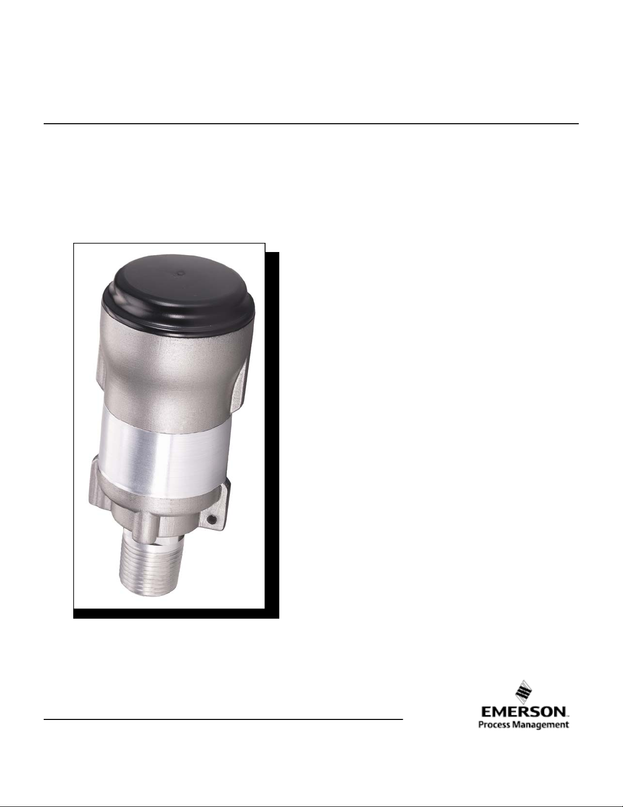
Smart Wir eless THUM™ Adapter
Page 2

Page 3

Reference Manual
00809-0100-0775, Rev AA
March 2009
Smart Wireless THUM Adapter Hardware Revision 1
HART® Device Revision 1
Field Communicator Field Device Revision Dev v2.5 DD v4
Read this manual before working with the product. For personal and system safety, and for
optimum product performance, make sure to thoroughly understand the contents before
installing, using, or maintaining this product.
The United States has two toll-free assistance numbers and one international number.
Customer Central
1-800-999-9307 (7:00 a.m. to 7:00 P.M. CST)
National Response Center
1-800-654-7768 (24 hours a day)
Equipment service needs
International
1-(952) 906-8888
Smart Wireless THUM Adapter
Smart Wir eless THUM™ Adapter
NOTICE
CAUTION
The products described in this document are NOT designed for nuclear-qualified
applications.
Using non-nuclear qualified products in applications that require nuclear-qualified hardware
or products may cause inaccurate readings.
For information on Rosemount nuclear-qualified products, contact a Emerson Process
Management Sales Representative.
The Smart Wireless THUM Adapter may be protected by one or more U.S. Patents pending. Other
foreign patents pending.
Page 4
Reference Manual
00809-0100-0775, Rev AA
March 2009
Explosions could result in death or serious injury:
Installation of this transmitter in an explosive environment must be in accordance
with the appropriate local, national, and international standards, codes, and
practices. Please review the approvals section of the THUM reference manual for any
restrictions associated with a safe installation.
• Before connecting a Field Communicator in an explosive atmosphere, ensure the
instruments are installed in accordance with intrinsically safe or non-incendive
field wiring practices.
Process leaks may cause harm or result in death.
• Install and tighten process connectors before applying pressure.
Electrical shock can result in death or serious injury.
• Avoid contact with the leads and terminals. High voltage that may be present on
leads can cause electrical shock.
NOTICE
The THUM and all other wireless devices should be installed only after the Smart Wireless Gateway has been installed and is
functioning properly. Wireless devices should also be powered up in order of proximity from the Gateway, beginning with the
closest. This will result in a simpler and faster network installation.
Smart Wireless THUM Adapter
NOTICE
NOTICE
Page 5

Reference Manual
00809-0100-0775, Rev AA
March 2009
Section 1 Overview
Safety Messages . . . . . . . . . . . . . . . . . . . . . . . . . . . . . . . . . page 1-1
Overview . . . . . . . . . . . . . . . . . . . . . . . . . . . . . . . . . . . . . . . page 1-2
Considerations . . . . . . . . . . . . . . . . . . . . . . . . . . . . . . . . . . page 1-3
Return of Materials . . . . . . . . . . . . . . . . . . . . . . . . . . . . . . . page 1-4
Smart Wireless THUM Adapter
SAFETY
MESSAGES
Warnings
Instructions and procedures in this section may require special precautions to
ensure the safety of the personnel performing the operations. Information that
potentially raises safety issues is indicated by a warning symbol ( ). Please
refer to the following safety messages before performing an operation
preceded by this symbol.
WARNING
Failure to follow these installation guidelines could result in death or
serious injury.
•Make sure only qualified personnel perform the installation.
Explosions could result in death or serious injury.
• Before connecting a 375 Field Communicator in an explosive atmosphere, make
sure the instruments are installed in accordance with intrinsically safe or
non-incendive field wiring practices.
• Verify that the operating atmosphere of the transmitter is consistent with the
appropriate hazardous locations certifications.
Electrical shock could cause death or serious injury.
• Use extreme caution when making contact with the leads and terminals.
Page 6

Reference Manual
00809-0100-0775, Rev AA
March 2009
Overview
This manual is designed to assist in the installation, operation, and
Manual
Transmitter
maintenance of Smart Wireless THUM Adapter.
Section 1: Overview
• Manual and Transmitter Overview
• Considerations
• Return of Materials
Section 2: Configuration
• Device Sensor Configuration
• Device Network Configuration
Section 3: Mounting
• Mount the Sensor
• Sensor Assembly/Leads
• Grounding
Section 4: Commissioning
• Network Status
• Verify Operation
Section 5: Operation and Maintenance
Appendix A: Specifications and Reference Data
• Specifications
• Dimensional drawings
• Ordering Information
Appendix B: Approvals
• Product Certifications
• Installation Drawings
Features of the Smart Wireless THUM Adapter include:
• An installation-ready solution that provides a variety of mounting
options, and transmitter configurations
• Flexibility to meet your most demanding applications
• Wireless output with >99% data reliability delivers rich HART data,
protected by industry leading security
• Works with any 2 or 4 wire HART 5.0 or new Device
• Does not affect the approval of the sub-device
Smart Wireless THUM Adapter
Page 7

Reference Manual
00809-0100-0775, Rev AA
March 2009
Considerations
The Smart Wireless THUM Adapter is connected to a HART sub-device. With simple HART configu-
General
Commissioning
Mechanical
Electrical
ration, the THUM transmits the HART information from the sub-device unto the WirelessHART network.
The THUM can be commissioned before or after installation. It may be
useful to commission it on the bench, before installation, to ensure proper
operation and to become familiar with its functionality. When applicable, make
sure the instruments are installed in accordance with intrinsically safe or
non-incendive field wiring practices. The device will be powered whenever THUM is
connected to a powered loop.
Location
When choosing an installation location and position, take into account the
need for access to the transmitter. For best performance, the antenna should
be vertical with some space between objects in a parallel metal plane such as
a pipe or metal framework, as the pipes or framework may adversely affect
the performance of the antenna.
THUM Power Options
The THUM has two power options; variable current, and fixed current mode.
Variable Current
Variable current mode is the mode that the THUM should be in if the current on the 4-20 mA loop can
change between 4 to 20 mA. The THUM will drop 2.25 volts at 2.5 mA and 1 volt at 25 mA. The
voltage drop is linear between these two points. The THUM will operate
according to standard specifications under this mode.
Fixed Current
Fixed current mode can only be used when the current of the loop will never fall below 20 mA. The
THUM will always drop 1 volt across the loop. If the current of the loop falls below 20 mA the
THUM, and the rest of the wireless network may not function properly.
Smart Wireless THUM Adapter
This symbol represents protective earth grounding.
Page 8
Reference Manual
00809-0100-0775, Rev AA
March 2009
Smart Wireless THUM Adapter
Environmental
RETURN OF
MATERIALS
Verify that the operating atmosphere of the transmitter is consistent with the
appropriate hazardous locations certifications.
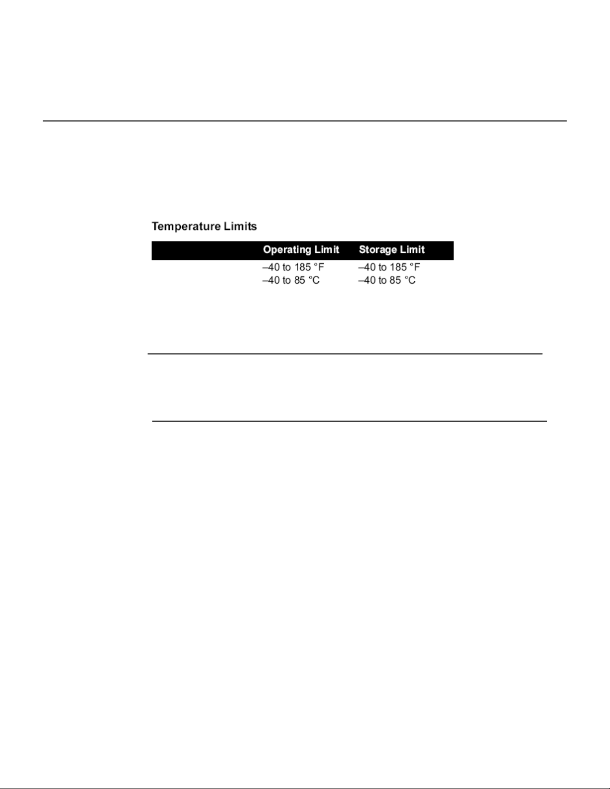
Temperature Effects
The transmitter will operate within specifications for ambient temperatures
between –40 and 185 °F (–40 and 85 °C).
To expedite the return process in North America, call the Emerson Process
Management National Response Center toll-free at 800-654-7768. This
center, available 24 hours a day, will assist you with any needed information
or materials.
The center will ask for the following information:
• Product model
• Serial numbers
• The last process material to which the product was exposed
The center will provide
• A Return Material Authorization (RMA) number
• Instructions and procedures that are necessary to return goods that
were exposed to hazardous substances
For other locations outside North America, please contact an Emerson
Process Management sales representative for further instructions.
NOTE
If the device has been exposed to a hazardous substance, a Material Safety
Data Sheet (MSDS) must be included with the returned materials. An MSDS
is required by law to be available to people exposed to specific hazardous
substances.
Page 9

Reference Manual
00809-0100-0775, Rev AA
March 2009
Section 2 Configuration
Safety Messages . . . . . . . . . . . . . . . . . . . . . . . . . . . . . . . . . page 2-1
Device Sensor Configuration . . . . . . . . . . . . . . . ... . . . . . . page 2-2
Device Network Configuration . . . . . . . . . . . . . .. . . . . . . . page 2-2
Smart Wireless THUM Adapter
SAFETY
MESSAGES
Warnings
Instructions and procedures in this section may require special precautions to
ensure the safety of the personnel performing the operations. Information that
potentially raises safety issues is indicated by a warning symbol ( ). Please
refer to the following safety messages before performing an operation
preceded by this symbol.
WARNING
Failure to follow these installation guidelines could result in death or
serious injury.
•Make sure only qualified personnel perform the installation.
Explosions could result in death or serious injury.
• Before connecting a 375 Field Communicator in an explosive atmosphere, make
sure the instruments are installed in accordance with intrinsically safe or
non-incendive field wiring practices.
• Verify that the operating atmosphere of the transmitter is consistent with the
appropriate hazardous locations certifications.
Electrical shock could cause death or serious injury.
• Use extreme caution when making contact with the leads and terminals.
This device complies with Part 15 of the FCC Rules. Operation is subject to the following
conditions: This device may not cause harmful interference, this device must accept any
interference received, including interference that may cause undesired operation.
This device must be installed to ensure a minimum antenna separation distance of 20 cm
from all persons.
Page 10

Reference Manual
00809-0100-0775, Rev AA
March 2009
Smart Wireless THUM Adapter
Connections
THUM Configuration
DEVICE NETWORK
CONFIGURATION
The THUM is compatible with a number of sub-devices. See section 3 for details on wiring the
THUM to different types of sub-devices.
The THUM will receive any HART communication from a handheld Field Communicator, or AMS
In order for the THUM to receive HART communication the sub-device must be powered. When using a Field communicator polling must be turned on, the default HART address for the THUM is address 15. When using a Field Communicator, any configuration changes must be sent to the transmitter using the Send key (F2). AMS configuration changes are implemented when the Apply button is
clicked.
AMS
® Wireless Configurator
AMS is capable of connecting to devices directly, using a HART modem, or with the Gateway. When
configuring on the bench with a HART modem, double click the device icon, then choose the Configure/Setup tab (or right click and select Configure/Setup). Configure the device settings using the Direct
Connection menu. When configuring with the Gateway, double click the device icon then choose the
Configure/Setup tab (or right click and select Configure/Setup). Configure the device settings using the
Wireless Connection menu. To check or change sensor configuration using a 375 Field Communicator,
enter the following Fast Key Sequence: 2, 1, 3.
To communicate with the Gateway, and ultimately the Information System, the transmitter must be
configured to communicate with the wireless network. Using a Field Communicator or AMS, enter the
Network ID and Join Key so they match the Network ID and Join Key of the Gateway and the other
devices in the network. If the Network ID and Join Key are not identical, the transmitter will not communicate with the network. The Network ID and Join Key may be obtained from the Gateway on the
Setup>Network>Settings page on the web server. Using a 375 Field Communicator, the Network ID
can be configured by entering the Fast Key Sequence: 2, 2, 1, 1. The Join Key can also be configured
using a 375 Field Communicator with the Fast Key Sequence: 2, 2, 1, 2.
The final device network configuration piece is the Update Rate. There are three update rates for the
THUM. Each Update Rate can be configured independently of the other two. One of the Updates is
for THUM specific information such as THUM temperature and communication status. The other two
Update Rates are for sub-device information. The information that is sent for the sub-device and the
frequency that it is sent can all be changed at commissioning or at any other time. At default the Update Rate for all three Updates is 1 minute. The Updates can be changed using AMS or a 375 Field
Communicator.
®.
Page 11

Reference Manual
00809-0100-0775, Rev AA
March 2009
Section 3 Mounting
Safety Messages . . . . . . . . . . . . . . . . . . . . . . . . . . . . . . . . . page 3-1
Mounting . . . . . . . . . . . . . . . . . . . . . . . . . . . . . . . . . . . . . . . page 3-2
Direct Mount . . . . . . . . . . . . . . . . . . . . . . . . . . . . . . . . . . . . page 3-2
Remote Mount . . . . . . . . . . . . . . . . . . . . . . . . . . . . . . . . . . . page 3-4
Ground the Transmitter . . . . . . . . . . . . . . . . . . . . . . . . . . . ..page 3-5
Smart Wireless THUM Adapter
SAFETY
MESSAGES
Warnings
Instructions and procedures in this section may require special precautions to
ensure the safety of the personnel performing the operations. Information that
potentially raises safety issues is indicated by a warning symbol ( ). Please
refer to the following safety messages before performing an operation
preceded by this symbol.
WARNING
Failure to follow these installation guidelines could result in death or
serious injury.
•Make sure only qualified personnel perform the installation.
Explosions could result in death or serious injury.
• Before connecting a 375 Field Communicator in an explosive atmosphere, make
sure the instruments are installed in accordance with intrinsically safe or
non-incendive field wiring practices.
• Verify that the operating atmosphere of the transmitter is consistent with the
appropriate hazardous locations certifications.
Electrical shock could cause death or serious injury.
• Use extreme caution when making contact with the leads and terminals.
This device complies with Part 15 of the FCC Rules. Operation is subject to the following
conditions: This device may not cause harmful interference, this device must accept any
interference received, including interference that may cause undesired operation.
This device must be installed to ensure a minimum antenna separation distance of 20 cm
from all persons.
Page 12

Reference Manual
00809-0100-0775, Rev AA
March 2009
Smart Wireless THUM Adapter
Mounting
Direct Mount
Remount Mount
The THUM can be installed in one of two configurations: Direct Mount, where the THUM is
connected directly to the conduit entry of the sub-device, or Remote Mount, where the THUM is
mounted separate from the sub-device housing, then connected to the sub-device via conduit. Choose
the installation sequence that corresponds to the mounting configuration.
1. Install the HART® device according to standard installation practices, being sure to use
thread sealant on all connections.
2. Using the threaded conduit entry attach the THUM to the HART® device making sure to
position the THUM in a vertical position, using a 90-degree elbow, if necessary.
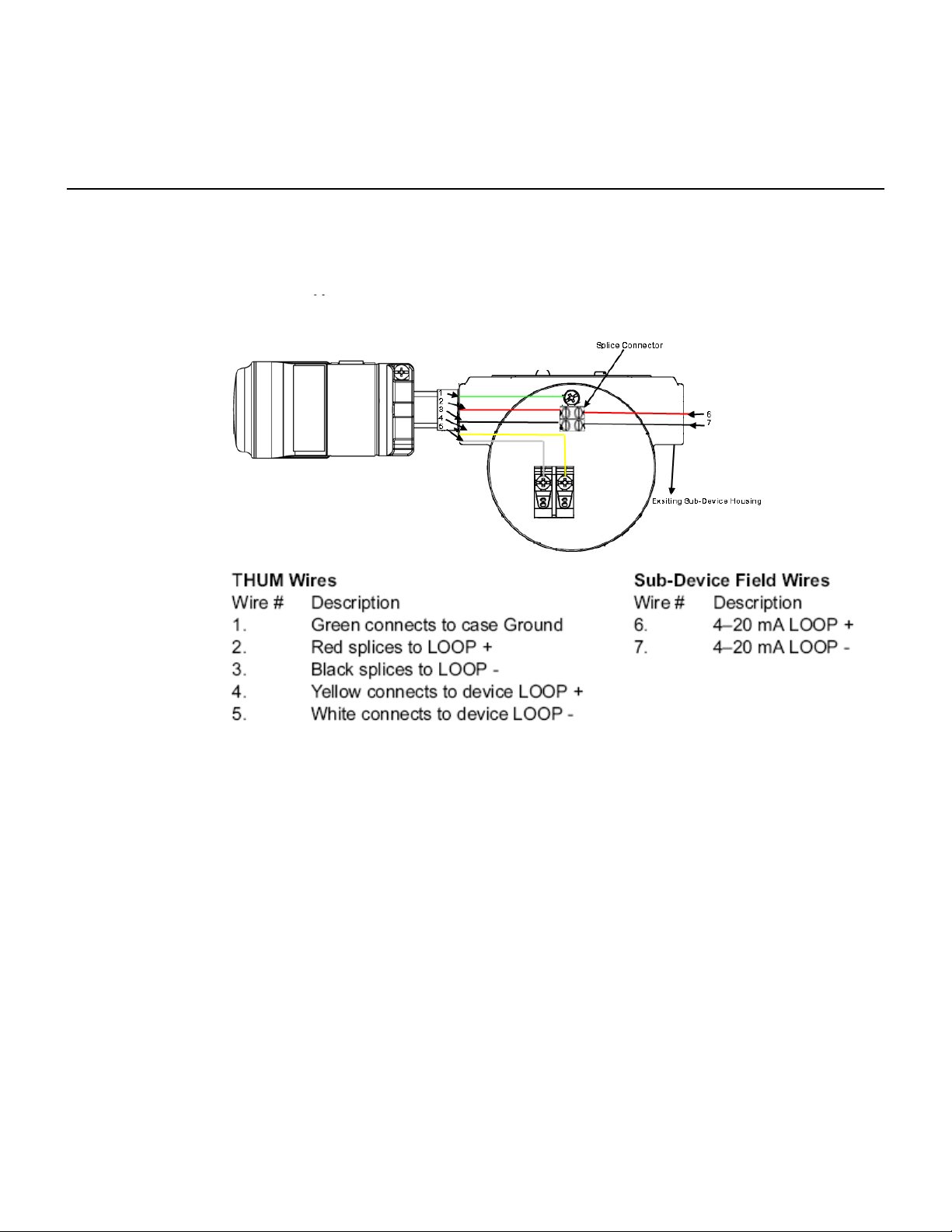
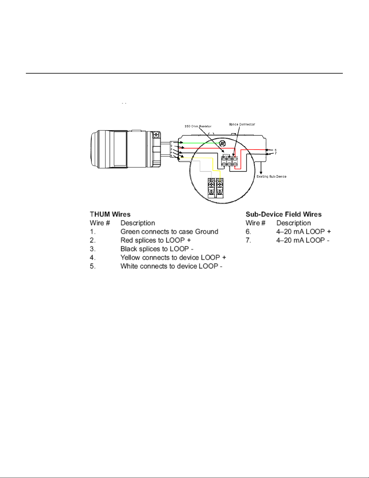
3. Connect the THUM to the HART® sub-device using the wiring diagrams below. See
Figures 1, 2, 3, and 4 on the following pages.
4. Close the housing cover on the HA RT® device, so that metal touches metal, and tighten
to safety specifications. Please note that the unit may be damaged by over tightening the
cover.
NOTE
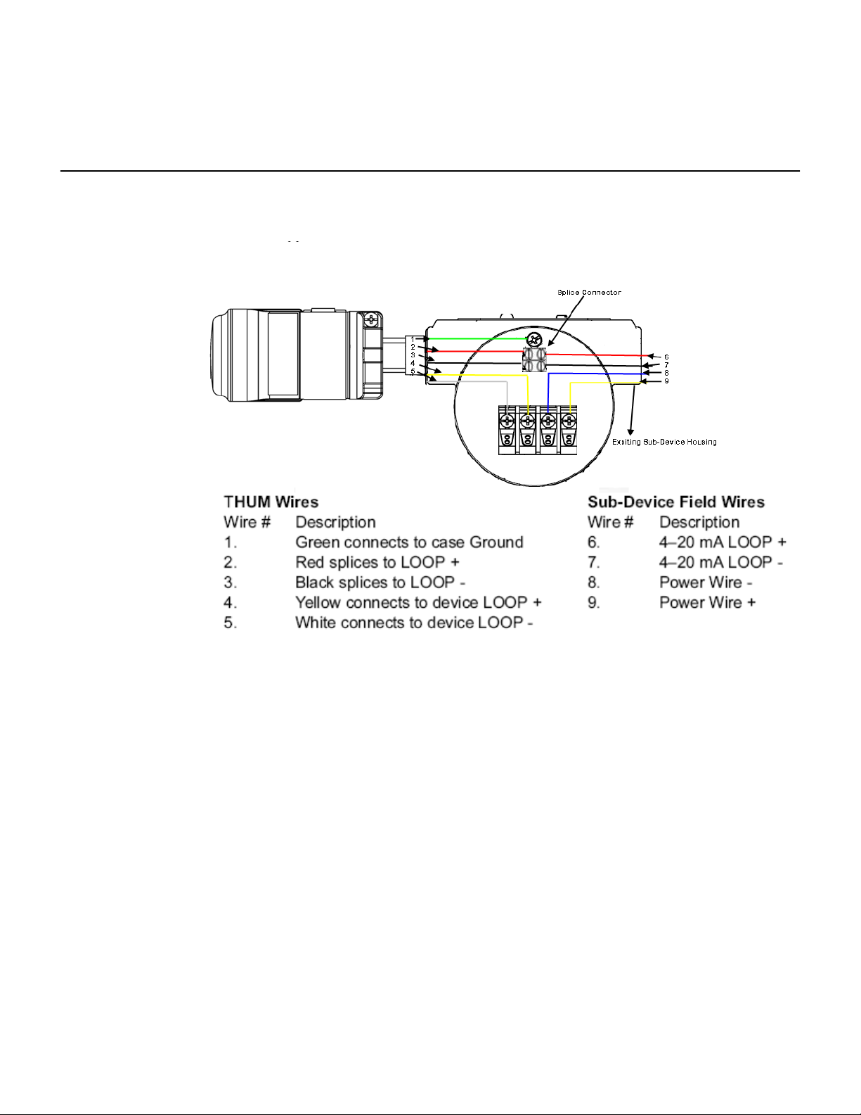
The THUM includes two euro splice connectors. The first is a two compartment splice. The second is a
three compartment splice which contains a 250 Ohm resistor, to be used if there is not 250 Ohms of
resistance in the loop.
1. Install the HART® device according to standard installation practices, being sure to use
thread sealant on all connections.
2. Mount the THUM in a location for good wireless network communication. Make sure to mount the
THUM in a vertical position.
3. Using standard practices connect the THUM wires to the sub-device.
4. Wire the THUM to the HART® sub-device using the wiring diagrams below. See
Figures 1, 2, 3, and 4 on the following pages.
5. Close the housing cover on the HA RT® device, so that metal touches metal, and tighten
to safety specifications. Please note that the unit may be damaged by over tightening the
cover.
NOTE
The THUM includes two euro splice connectors. The first is a two compartment splice. The second is a
three compartment splice which contains a 250 Ohm resistor, to be used if there is not 250 Ohms of
resistance in the loop.
Page 13
Reference Manual
00809-0100-0775, Rev AA
March 2009
Smart Wireless THUM Adapter
Wiring
Figure 1. 2 Wire Sub-Device Plus THUM Wiring Dia gram
NOTE:
In order for the THUM to function properly there must be 250 Ohms resistance in the
loop. If the 4–20 mA loop does not have 250 Ohms resistance, wire a 250 Ohm
resistor as shown in Figure 2.
Page 14
Reference Manual
00809-0100-0775, Rev AA
March 2009
Smart Wireless THUM Adapter
Wiring
Figure 2. 2 Wire Sub-Device Plus THUM Wiring Dia gram with 250 Ohm Resistor
NOTE:
In order for the THUM to function properly there must be 250 Ohms resistance in the
loop. If the 4–20 mA loop does not have 250 Ohms resistance, wire a 250 Ohm
resistor as shown in Figure 2.
Page 15
Reference Manual
00809-0100-0775, Rev AA
March 2009
Smart Wireless THUM Adapter
Wiring
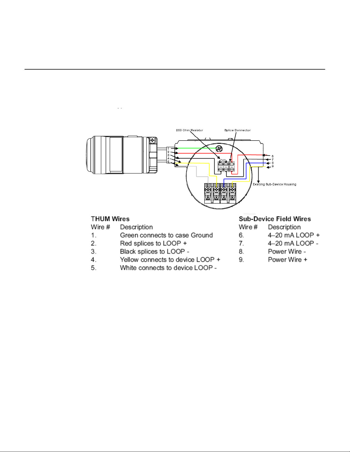
Figure 3. 4-Wire Sub-Device with Passive 4–20 mA LOOP Plus THUM Wiring Diagram
NOTE:
In order for the THUM to function properly there must be 250 Ohms resistance in the
loop. If the 4–20 mA loop does not have 250 Ohms resistance, wire a 250 Ohm
resistor as shown in Figure 4.
Page 16
Reference Manual
00809-0100-0775, Rev AA
March 2009
Smart Wireless THUM Adapter
Wiring
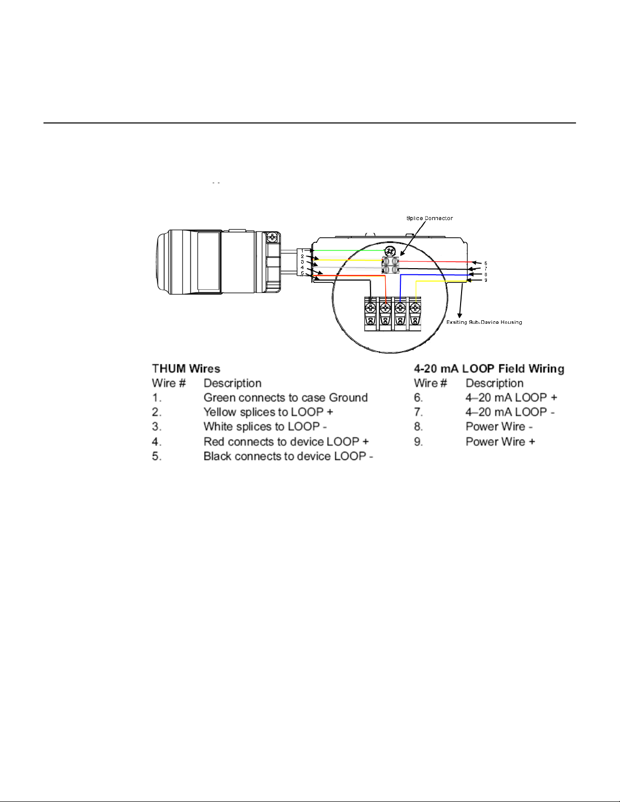
Figure 4. 4-Wire Sub-Device with Passive 4–20 mA LOOP Plus THUM Wiring Diagram with 250
Ohm resistor
NOTE:
In order for the THUM to function properly there must be 250 Ohms resistance in the
loop. If the 4–20 mA loop does not have 250 Ohms resistance, wire a 250 Ohm
resistor as shown in Figure 4.
Page 17
Reference Manual
00809-0100-0775, Rev AA
March 2009
Smart Wireless THUM Adapter
Wiring
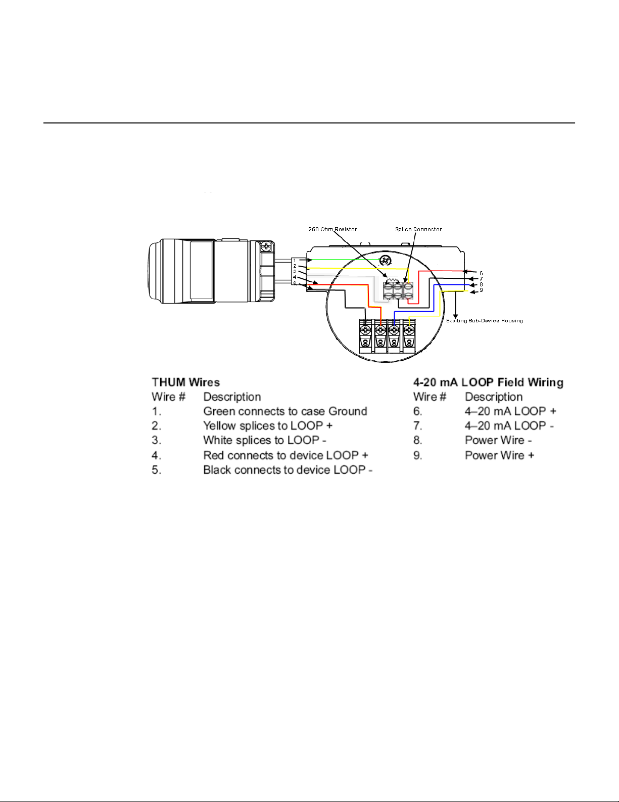
Figure 5. 4-Wire Sub-Device with Active 4–20 mA LOOP Pl us TH UM Wi ri ng Diagram
NOTE:
In order for the THUM to function properly there must be 250 Ohms resistance in the
loop. If the 4–20 mA loop does not have 250 Ohms resistance, wire a 250 Ohm
resistor as shown in Figure 6.
Page 18
Reference Manual
00809-0100-0775, Rev AA
March 2009
Smart Wireless THUM Adapter
Wiring
Figure 6. 4-Wire Sub-Device with Active 4–20 mA LOOP Plus THUM Wiring Diagram with 250
Ohm resistance
NOTE:
In order for the THUM to function properly there must be 250 Ohms resistance in the
loop. If the 4–20 mA loop does not have 250 Ohms resistance, wire a 250 Ohm
resistor as shown in Figure 6.
Page 19
Reference Manual
00809-0100-0775, Rev AA
March 2009
Smart Wireless THUM Adapter
Wiring
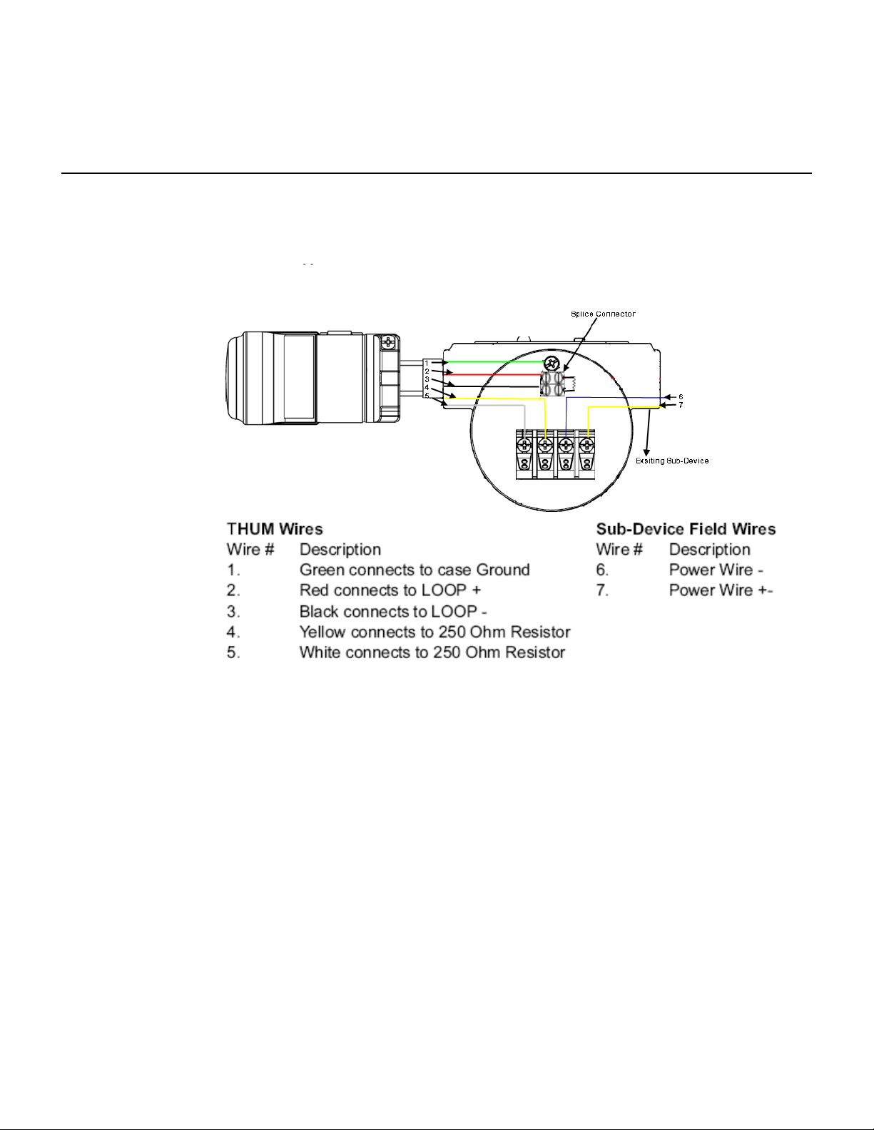
Figure 7. 4-Wire Sub-Device with no 4–20 mA LOOP Plus THUM Wiring Diagram
NOTE:
In order for the THUM to function properly there must be 250 Ohms resistance in the
loop. If the 4–20 mA loop does not have 250 Ohms resistance, wire a 250 Ohm
resistor as shown in Figure 7.
Page 20

Reference Manual
00809-0100-0775, Rev AA
March 2009
Section 4 Commissioning
Safety Messages . . . . . . . . . . . . . . . . . . . . . . . . . . . . . . . . . page 3-1
Verify Operations . . . . . . . . . . . . . . . . . . . . . . . . . . . . . . . . page 3-2
Smart Wireless THUM Adapter
SAFETY
MESSAGES
Warnings
Instructions and procedures in this section may require special precautions to
ensure the safety of the personnel performing the operations. Information that
potentially raises safety issues is indicated by a warning symbol ( ). Please
refer to the following safety messages before performing an operation
preceded by this symbol.
WARNING
Failure to follow these installation guidelines could result in death or
serious injury.
•Make sure only qualified personnel perform the installation.
Explosions could result in death or serious injury.
• Before connecting a 375 Field Communicator in an explosive atmosphere, make
sure the instruments are installed in accordance with intrinsically safe or
non-incendive field wiring practices.
• Verify that the operating atmosphere of the transmitter is consistent with the
appropriate hazardous locations certifications.
Electrical shock could cause death or serious injury.
• Use extreme caution when making contact with the leads and terminals.
This device complies with Part 15 of the FCC Rules. Operation is subject to the following
conditions: This device may not cause harmful interference, this device must accept any
interference received, including interference that may cause undesired operation.
This device must be installed to ensure a minimum antenna separation distance of 20 cm
from all persons.
Page 21
Reference Manual
00809-0100-0775, Rev AA
March 2009
Smart Wireless THUM Adapter
Verify Operations
Operation can be verified in two locations, using the 375 Field Communicator, or at the Gateway via
the Wireless Gateway’s integrated web server.
375 Field Communicator
To verify device operation using a HART Field Communicator, a 648 DD is
required.
Smart Wireless Gateway
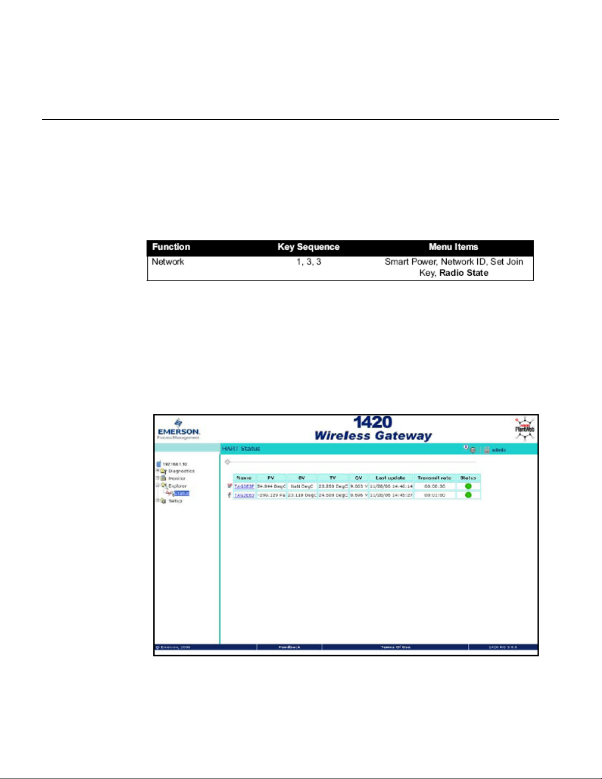
To verify device operation using the 1420 Wireless Gateway’s integrated web
server, navigate to the Explorer>Status page. This page will show whether
the device has joined the network and if it is communicating properly.
If the THUM was configured with the Network ID and Join Key and sufficient time for network polling has passed, the transmitter will be connected to the network. To verify connectivity, open the 1420
Wireless Gateway’s integral web interface and navigate to the Explorer>Status page.
Page 22
Reference Manual
00809-0100-0775, Rev AA
March 2009
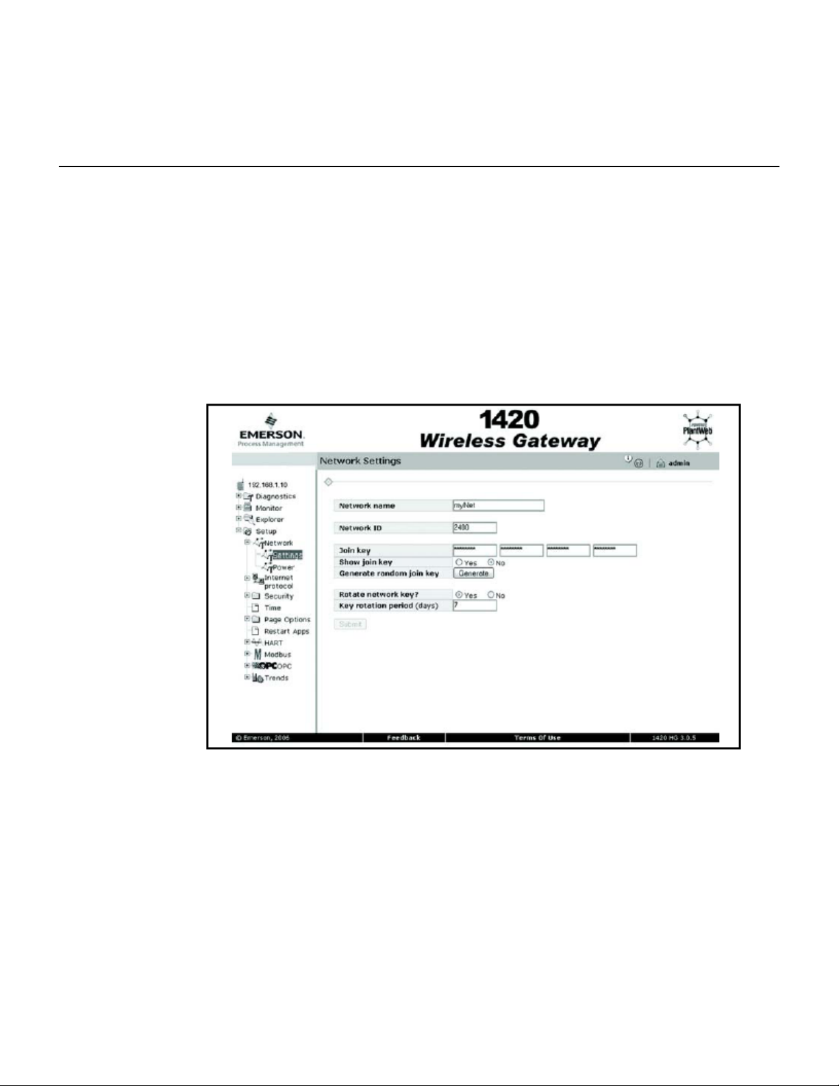
This page will display the transmitter’s tag, PV, SV, TV, QV, Last Update, Update Rate, Battery Voltage, and Status. A green status indicator means that the device is working properly. A red indicator
means that there is a problem with either the device or its communication path. For more detail on a
specific device, click on the tag name.
Troubleshooting
The most common cause of incorrect operation is the Network ID and Join Key. The Network ID and
Join Key in the device must match that of the Gateway. The Network ID and Join Key may be obtained
from the Gateway on the Setup>Network>Settings page on the web server.
Smart Wireless THUM Adapter
Page 23

Reference Manual
00809-0100-0775, Rev AA
March 2009
Section 5 Operations and Maintenance
Safety Messages . . . . . . . . . . . . . . . . . . . . . . . . . . . . . . . . . page 5-1
LCD Screen Messages . . . . . . . . . . . . . . . . . . . . . . . . . . . . page 5-2
Smart Wireless THUM Adapter
SAFETY
MESSAGES
Warnings
Instructions and procedures in this section may require special precautions to
ensure the safety of the personnel performing the operations. Information that
potentially raises safety issues is indicated by a warning symbol ( ). Please
refer to the following safety messages before performing an operation
preceded by this symbol.
WARNING
Failure to follow these installation guidelines could result in death or
serious injury.
•Make sure only qualified personnel perform the installation.
Explosions could result in death or serious injury.
• Before connecting a 375 Field Communicator in an explosive atmosphere, make
sure the instruments are installed in accordance with intrinsically safe or
non-incendive field wiring practices.
• Verify that the operating atmosphere of the transmitter is consistent with the
appropriate hazardous locations certifications.
Electrical shock could cause death or serious injury.
• Use extreme caution when making contact with the leads and terminals.
This device complies with Part 15 of the FCC Rules. Operation is subject to the following
conditions: This device may not cause harmful interference, this device must accept any
interference received, including interference that may cause undesired operation.
This device must be installed to ensure a minimum antenna separation distance of 20 cm
from all persons.
Page 24
Reference Manual
00809-0100-0775, Rev AA
March 2009
Smart Wireless THUM Adapter
Startup Sequence
Diagnostic
Due to the power scavenging of the THUM different capabilities will be available at different times
after startup. Immediately after startup configuration of the THUM is available. This includes all network settings including Network ID and Join Key, and Update Rate. The THUM will not start to join
the network until the radio turns completely on. This will not happen until up to 3 minutes after startup
depending on the current of the loop.
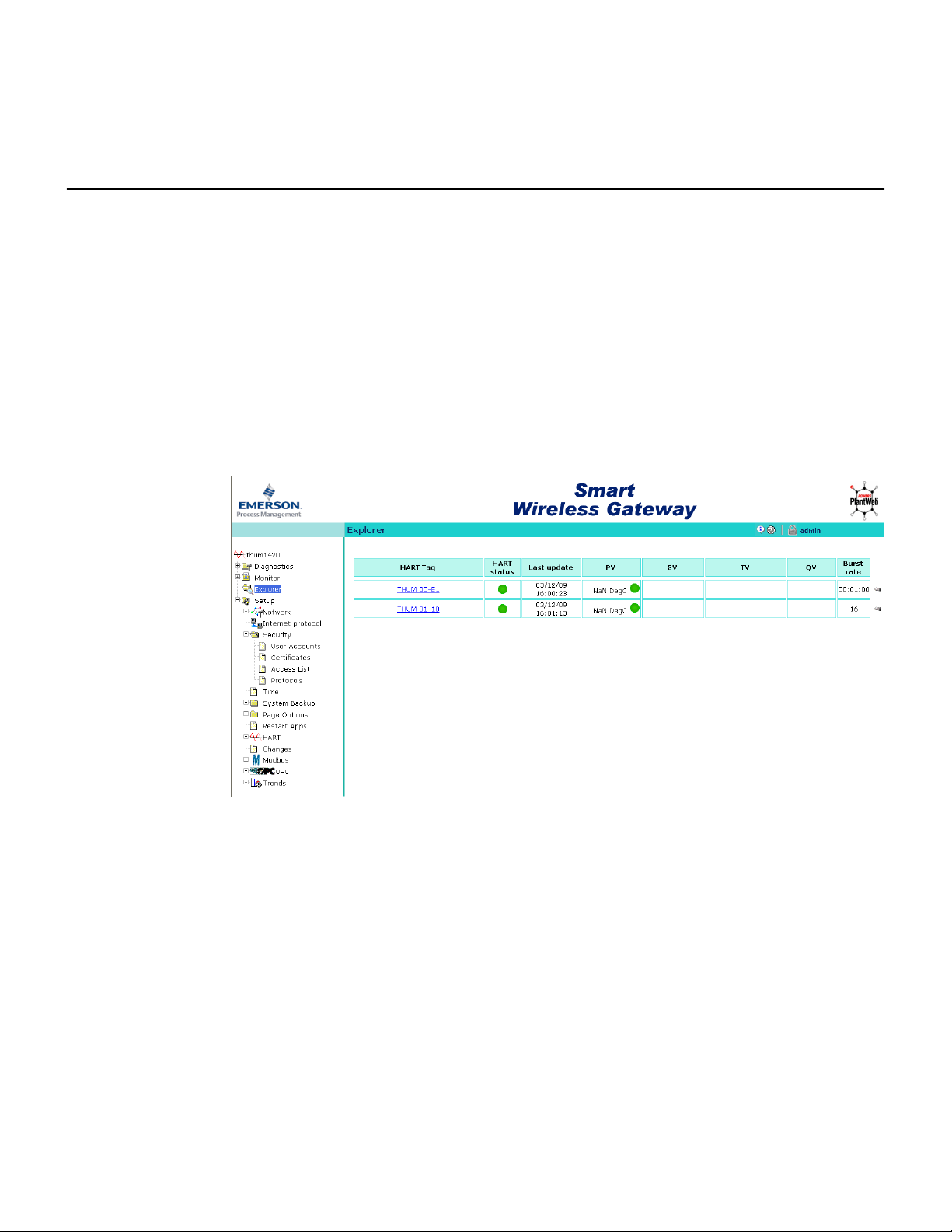
To determine if the THUM has joined the network, go to the Explorer page on the Gateway and look
for the THUM tag number as shown below.
Page 25

Reference Manual
00809-0100-0775, Rev AA
March 2009
Smart Wireless THUM Adapter
Appendix A
Specifications
Functional
Specifications
Physical
Specifications
Specifications and Reference Data
Specifications . . . . . . . . . . . . . . . . . . . . . . . . . . . . . . . . . . . page A-1
Dimensional Drawings . . . . . . . . . . . . . . . . . . . . . . . . . . . . page A-3
Ordering Information . . . . . . . . . . . . . . . . . . . . . . . . . . . . . page A-4
Input
Any 2- or 4-wire HART 5.0 powered device.
Output
WirelessHART.
Humidity Limits
0–100% relative humidity
Burst Rate
User selectable, 8 sec. to 60 min.
Electrical Connections
The THUM™ is connected into a powered 4–20 mA loop, powering itself by scavenging power. The THUM causes a voltage
drop across the loop. The drop is linear from 2.25 volts at 3.5 mA to 1.2 volts at 25 mA, but does not effect the 4–20mA signal
on the loop. Under fault conditions, the maximum voltage drop is 2.5 volts.
Power Supply
Minimum load on loop 250 Ohms to maintain normal operating functions of the sub-device, the power in the loop must have at
least a 2.5 V margin at a 250 Ohm load.
HART Communicator Connections
Utilize sub-device HART connections.
Materials of Construction
Enclosure
Housing - Low-copper aluminum
Paint - Polyurethane
Antenna
Poly butadine terephthalate (PBT)/Polycarbonate (PC) integrated omnidirectional antenna
Weight
.65 lbs. (.29 kg)
Enclosure Ratings
Housing option code D is NEMA 4X, and IP66.
Page 26

Reference Manual
00809-0100-0775, Rev AA
March 2009
Smart Wireless THUM Adapter
Performance
Specifications
ElectroMagnetic Compatibility (EMC)
All Models:
Meets all relevant requirements of EN61326-1 (2006)
.
Vibration Effect
Output unaffected when tested per the requirements of IEC60770-1 field or pipeline with high vibration level (10-60 Hz 0.21mm
displacement peak amplitude / 60-2000 Hz 3g). Output unaffected when tested per the requirements of
IEC60770-1 field with general application or pipeline with low vibration level (10-60 Hz 0.15mm displacement peak amplitude /
60-500 Hz 2g).
Temperature Limits
Output Specifications
The THUM™ allows WirelessHART™ communication between
the HART device it is connected to and the Smart Wireless
Gateway.
Page 27

Reference Manual
00809-0100-0775, Rev AA
March 2009
DIMENSIONAL DRAWINGS
Smart Wireless THUM Adapter
Page 28
Reference Manual
00809-0100-0775, Rev AA
March 2009
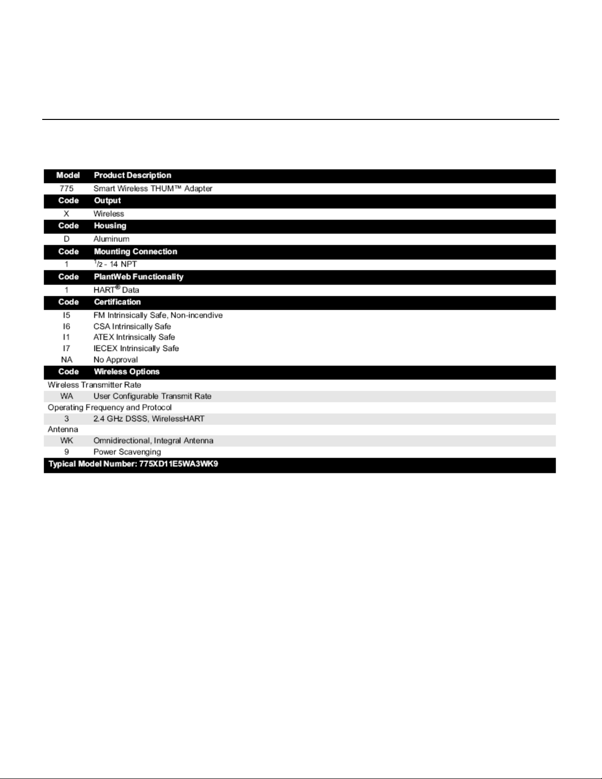
Ordering Information
Smart Wireless THUM Adapter
Page 29

Reference Manual
00809-0100-0775, Rev AA
March 2009
Smart Wireless THUM Adapter
Appendix B
Approved
Manufacturing
Locations
Telecommunication
Compliance
FCC and IC
European Union
Directive
Information
Ordinary Location
Certification for FM
Product Certifications
Approved Manufacturing Locations . . . . . . . . . . . . . . . . . page B-1
Telecommunication Compliance . . . . . . . . . . . . . . . . . . . . page B-1
European Union Directive Information . . . . . . . . . . . . . . . page B-1
Ordinary Location Certification for FM . . . . . . . . . . . . . . . page B-2
Hazardous Locations Certificates . . . . . . . . . . . . . . . . . . . page B-2
Rosemount Inc. – Chanhassen, Minnesota, USA
All wireless devices require certification to ensure that they adhere to regulations regarding the use of the RF spectrum. Nearly
every country requires this type of product certification. Emerson is working with governmental agencies around the world to
supply fully compliant products and remove the risk of violating country directives or laws governing wireless device usage.
This device complies with Part 15 of the FCC Rules. Operation is subject to the following conditions: This device may not cause
harmful interference. This device must accept any interference received, including interference that may cause undesired operation.
This device must be installed to ensure a minimum antenna
separation distance of 20 cm from all persons.
The EC declaration of conformity for all applicable European directives for this product can be found at www.rosemount.com. A
hard copy may be obtained by contacting an Emerson Process Management representative.
ATEX Directive (94/9/EC)
Emerson Process Management complies with the ATEX Directive.
Electro Magnetic Compatibility (EMC) (2004/108/EC)
Radio and Telecommunications Terminal Equipment Directive (R&TTE) (1999/5/EC)
Emerson Process Management complies with the R&TTE Directive.
As standard, the transmitter has been examined and tested to determine that the design meets basic electrical, mechanical, and
fire protection requirements by FM, a nationally recognized testing laboratory (NRTL) as accredited by the Federal Occupational
Safety and Health Administration (OSHA).
Emerson Process Management complies with the EMC Directive
Page 30

Reference Manual
00809-0100-0775, Rev AA
March 2009
Smart Wireless THUM Adapter
Hazardous
Locations
Certificates
North American Certifications
Factory Mutual (FM) Approvals
I5 FM Intrinsic Safety and Non-incendive
Intrinsically Safe for Class I/II/III, Division 1, Groups A, B, C, D,E, F, and G.
Zone Marking: Class I, Zone 0, AEx ia llC
Temperature Codes T4 (T
Non-incendive for Class I, Division 2, Groups A, B, C, and D.
Intrinsically safe and non-incendive when installed according
to Rosemount Drawing 00775-XXXX.
Enclosure Type 4X/IP66
amb = -50 to 70° C)
Warning: The antenna does not meet the surface resistivity requirements and,
to avoid electrostatic charging, it must only be cleaned with a damp cloth.
CSA - Canadian Standards Association
I6 CSA Intrinsic Safety
Intrinsically Safe for Class I, Division 1, Groups A, B, C, and D.
Intrinsically safe and non-incendive when installed according
to Rosemount Drawing 00775-XXXX
Warning: The antenna does not meet the surface resistivity requirements and,
to avoid electrostatic charging, it must only be cleaned with a damp cloth.
European Certifications
I1 ATEX Intrinsic Safety
Certificate No.: See Certificate II 1G
Ex ia IIC T5 (T
Ex ia IIC T4 (T
IP66
Special Conditions of Safe Use (X)
The antenna does not meet the surface resistivity requirements and, to avoid
electrostatic charging, it must only be cleaned with a damp cloth.
a = -50 °C to 40 °C)
a = -50 °C to 70 °C)
Page 31
Reference Manual
00809-0100-0775, Rev AA
March 2009
Smart Wireless THUM Adapter
Hazardous
Locations
Certificates
IECEx Certifications
I7 IECEx Intrinsic Safety
Certificate No.: See Certificate
Ex ia IIC T5 (T
Ex ia IIC T4 (T
IP66
Special Conditions of Safe Use (X)
The antenna does not meet the surface resistivity requirements and, to avoid
electrostatic charging, it must only be cleaned with a damp cloth.
amb = -50 °C to 40 °C)
amb = -50 °C to 70 °C)
Page 32
Reference Manual
00809-0100-0775, Rev AA
March 2009
Smart Wireless THUM Adapter
 Loading...