


 Loading...
Reference Manual
00809-0100-4809, Rev AA
August 2002
The Annubar® Flowmeter Series
Model 3095MFA
Mass ProBar
Model 3051SFA
ProBar®
Model 485
Annubar® Primary
www.rosemount.com

Reference Manual
00809-0100-4809, Rev AA
August 2002
Annubar Flowmeter Series
The Annubar Flowmeter Series
NOTICE
Read this manual before working with the product. For personal and system safety, and for optimum product performance, make sure you thoroughly understand the contents before installing, using, or maintaining this product.
The United States has two toll-free assistance numbers and one International number.
Customer Central
1-800-999-9307 (7:00 a.m. to 7:00 P.M. CST)
International
1-(952) 906-8888
National Response Center
1-800-654-7768 (24 hours a day) Equipment service needs
The products described in this document are NOT designed for nuclear-qualified applications. Using non-nuclear qualified products in applications that require nuclear-qualified hardware or products may cause inaccurate readings.
For information on Rosemount nuclear-qualified products, contact your local Rosemount
Sales Representative.
This device is intended for use in temperature monitoring applications and should not be used in control and safety applications.
May be protected by one or more of the following U.S. Patent Nos.4,559,836; 4,717,159; 5,710,370; 5,773,726; 4,633, 713; and various foreign patents. Other foreign patents issued and pending.
www.rosemount.com

Reference Manual
00809-0100-4809, Rev AA
June 2002
Annubar Flowmeter Series
Table of Contents
SECTION 1
Introduction
SECTION 2
Installation
SECTION 3
Commissioning
Using This Manual . . . . . . . . . . . . . . . . . . . . . . . . . . . . . . . . . . . . . . . . 1-1
Receiving and Inspection. . . . . . . . . . . . . . . . . . . . . . . . . . . . . . . . . . . 1-2
Returning the Product . . . . . . . . . . . . . . . . . . . . . . . . . . . . . . . . . . . . . 1-2
Considerations. . . . . . . . . . . . . . . . . . . . . . . . . . . . . . . . . . . . . . . . . . . 1-2
Limitations . . . . . . . . . . . . . . . . . . . . . . . . . . . . . . . . . . . . . . . . . . . 1-2
Environmental. . . . . . . . . . . . . . . . . . . . . . . . . . . . . . . . . . . . . . . . . 1-3
Process Considerations . . . . . . . . . . . . . . . . . . . . . . . . . . . . . . . . . 1-4
Electrical . . . . . . . . . . . . . . . . . . . . . . . . . . . . . . . . . . . . . . . . . . . . . 1-5
Safety Messages . . . . . . . . . . . . . . . . . . . . . . . . . . . . . . . . . . . . . . . . . 2-1
Installation Flowchart and Checklist . . . . . . . . . . . . . . . . . . . . . . . . . . 2-2
Mounting . . . . . . . . . . . . . . . . . . . . . . . . . . . . . . . . . . . . . . . . . . . . . . . 2-4
Tools and Supplies . . . . . . . . . . . . . . . . . . . . . . . . . . . . . . . . . . . . . 2-4
Mounting Brackets . . . . . . . . . . . . . . . . . . . . . . . . . . . . . . . . . . . . . 2-4
Bolt Installation Guidelines . . . . . . . . . . . . . . . . . . . . . . . . . . . . . . . 2-4
Instrument Manifolds . . . . . . . . . . . . . . . . . . . . . . . . . . . . . . . . . . . 2-5
Straight Run Requirements . . . . . . . . . . . . . . . . . . . . . . . . . . . . . . 2-6
Integral (Direct) Mount . . . . . . . . . . . . . . . . . . . . . . . . . . . . . . . . . . 2-8
Remote Mount . . . . . . . . . . . . . . . . . . . . . . . . . . . . . . . . . . . . . . . . 2-9
Installation . . . . . . . . . . . . . . . . . . . . . . . . . . . . . . . . . . . . . . . . . . . . . 2-12
Pak-Lok Model . . . . . . . . . . . . . . . . . . . . . . . . . . . . . . . . . . . . . . . 2-12
Flanged Model . . . . . . . . . . . . . . . . . . . . . . . . . . . . . . . . . . . . . . . 2-18
Flange-Lok Model. . . . . . . . . . . . . . . . . . . . . . . . . . . . . . . . . . . . . 2-23
Threaded Flo-Tap Model . . . . . . . . . . . . . . . . . . . . . . . . . . . . . . . 2-28
Flanged Flo-Tap Model . . . . . . . . . . . . . . . . . . . . . . . . . . . . . . . . 2-34
Connect the Wiring . . . . . . . . . . . . . . . . . . . . . . . . . . . . . . . . . . . . . . 2-40
Wiring Diagrams . . . . . . . . . . . . . . . . . . . . . . . . . . . . . . . . . . . . . . 2-40
Equipment . . . . . . . . . . . . . . . . . . . . . . . . . . . . . . . . . . . . . . . . . . 2-41
Field Wiring (Power and Signal) . . . . . . . . . . . . . . . . . . . . . . . . . . 2-42
Grounding. . . . . . . . . . . . . . . . . . . . . . . . . . . . . . . . . . . . . . . . . . . 2-42
Safety Messages . . . . . . . . . . . . . . . . . . . . . . . . . . . . . . . . . . . . . . . . . 3-1 Commissioning on the Bench (Model 3051SFA Only) . . . . . . . . . . . . 3-2 Set the Switches. . . . . . . . . . . . . . . . . . . . . . . . . . . . . . . . . . . . . . . 3-2 Commissioning The Annubar . . . . . . . . . . . . . . . . . . . . . . . . . . . . . . . 3-5 Direct Mount . . . . . . . . . . . . . . . . . . . . . . . . . . . . . . . . . . . . . . . . . . 3-5 Remote Mount . . . . . . . . . . . . . . . . . . . . . . . . . . . . . . . . . . . . . . . 3-10 Setting the Loop to Manual. . . . . . . . . . . . . . . . . . . . . . . . . . . . . . 3-14 Model 275 HART Communicator. . . . . . . . . . . . . . . . . . . . . . . . . . . . 3-14 Connections and Hardware . . . . . . . . . . . . . . . . . . . . . . . . . . . . . 3-14 Model 3051SFA Probar . . . . . . . . . . . . . . . . . . . . . . . . . . . . . . . . . . . 3-14 Updating the Model 275 HART Communication Software . . . . . . 3-15 HART Menu Tree . . . . . . . . . . . . . . . . . . . . . . . . . . . . . . . . . . . . . 3-15 Fast Key Sequences . . . . . . . . . . . . . . . . . . . . . . . . . . . . . . . . . . 3-17
www.rosemount.com

Annubar Flowmeter Series
Reference Manual
00809-0100-4809, Rev AA
June 2002
SECTION 4
Operation and
Maintenance
APPENDIX A
Specifications and
Reference Data
Review Configuration Data. . . . . . . . . . . . . . . . . . . . . . . . . . . . . . 3-17
Check Output . . . . . . . . . . . . . . . . . . . . . . . . . . . . . . . . . . . . . . . . 3-18
Basic Setup . . . . . . . . . . . . . . . . . . . . . . . . . . . . . . . . . . . . . . . . . 3-18
Detailed Setup . . . . . . . . . . . . . . . . . . . . . . . . . . . . . . . . . . . . . . . 3-20
Diagnostics and Service . . . . . . . . . . . . . . . . . . . . . . . . . . . . . . . . 3-20
Calibration . . . . . . . . . . . . . . . . . . . . . . . . . . . . . . . . . . . . . . . . . . 3-21
Advanced Functions . . . . . . . . . . . . . . . . . . . . . . . . . . . . . . . . . . . 3-30
Model 3095MFA Mass Probar . . . . . . . . . . . . . . . . . . . . . . . . . . . . . . 3-30
EA Software/ HART Communicator Comparison . . . . . . . . . . . . . 3-30
Engineering Assistant (EA) Software . . . . . . . . . . . . . . . . . . . . . . 3-31
Model 275 HART Communicator . . . . . . . . . . . . . . . . . . . . . . . . . 3-31
Safety Messages . . . . . . . . . . . . . . . . . . . . . . . . . . . . . . . . . . . . . . . . . 4-1
Model 3095MFA Mass Probar . . . . . . . . . . . . . . . . . . . . . . . . . . . . . . . 4-2
Troubleshooting . . . . . . . . . . . . . . . . . . . . . . . . . . . . . . . . . . . . . . . 4-2
Disassembly . . . . . . . . . . . . . . . . . . . . . . . . . . . . . . . . . . . . . . . . . . . . 4-3
Remove the Flowmeter from Service . . . . . . . . . . . . . . . . . . . . . . . 4-3
Terminal Block . . . . . . . . . . . . . . . . . . . . . . . . . . . . . . . . . . . . . . . . 4-3
Electronics Board . . . . . . . . . . . . . . . . . . . . . . . . . . . . . . . . . . . . . . 4-4
RTD Maintenance . . . . . . . . . . . . . . . . . . . . . . . . . . . . . . . . . . . . . . . . 4-5
Replacing a RTD . . . . . . . . . . . . . . . . . . . . . . . . . . . . . . . . . . . . . . 4-5
Model 3051SFA ProBar Flowmeter . . . . . . . . . . . . . . . . . . . . . . . . . . . A-1
Performance . . . . . . . . . . . . . . . . . . . . . . . . . . . . . . . . . . . . . . . . . . A-1
Functional . . . . . . . . . . . . . . . . . . . . . . . . . . . . . . . . . . . . . . . . . . . . A-2
Installation Considerations . . . . . . . . . . . . . . . . . . . . . . . . . . . . . . . A-4
Physical . . . . . . . . . . . . . . . . . . . . . . . . . . . . . . . . . . . . . . . . . . . . . A-4
Model 3095MFA Mass ProBar Flowmeter. . . . . . . . . . . . . . . . . . . . . . A-7
Performance . . . . . . . . . . . . . . . . . . . . . . . . . . . . . . . . . . . . . . . . . . A-7
Functional . . . . . . . . . . . . . . . . . . . . . . . . . . . . . . . . . . . . . . . . . . . . A-7
Installation Considerations . . . . . . . . . . . . . . . . . . . . . . . . . . . . . . . A-9
Physical . . . . . . . . . . . . . . . . . . . . . . . . . . . . . . . . . . . . . . . . . . . . . A-9
Model 485 Annubar Primary . . . . . . . . . . . . . . . . . . . . . . . . . . . . . . . A-12
Performance . . . . . . . . . . . . . . . . . . . . . . . . . . . . . . . . . . . . . . . . . A-12
Functional . . . . . . . . . . . . . . . . . . . . . . . . . . . . . . . . . . . . . . . . . . . A-12
Installation Considerations . . . . . . . . . . . . . . . . . . . . . . . . . . . . . . A-13
Physical . . . . . . . . . . . . . . . . . . . . . . . . . . . . . . . . . . . . . . . . . . . . A-13
Dimensional Drawings . . . . . . . . . . . . . . . . . . . . . . . . . . . . . . . . . . . . A-16
Model 3051SFA Pak–Lok Probar . . . . . . . . . . . . . . . . . . . . . . . . . A-16
Model 3051SFA Flange–Lok Probar . . . . . . . . . . . . . . . . . . . . . . A-17
Model 3051SFA Flange Probar . . . . . . . . . . . . . . . . . . . . . . . . . . A-18
Model 3051SFA Flange Flo–Tap Probar . . . . . . . . . . . . . . . . . . . A-19
Model 3051SFA Threaded Flo–Tap Probar . . . . . . . . . . . . . . . . . A-20
Model 3095MFA Pak–Lok Mass ProBar . . . . . . . . . . . . . . . . . . . A-21
Model 3095MFA Flange–Lok Mass ProBar . . . . . . . . . . . . . . . . . A-22
Model 3095MFA Flange Mass ProBar . . . . . . . . . . . . . . . . . . . . . A-23
Model 3095MFA Flange Flo–Tap Mass ProBar . . . . . . . . . . . . . . A-24
Model 3095MFA Threaded Flo–Tap Mass ProBar. . . . . . . . . . . . A-25
Model 485 Pak–Lok Annubar . . . . . . . . . . . . . . . . . . . . . . . . . . . . A-26
Model 485 Flange–Lok Annubar . . . . . . . . . . . . . . . . . . . . . . . . . A-27
Model 485 Flange Annubar . . . . . . . . . . . . . . . . . . . . . . . . . . . . . A-28
Model 485 Flange Flo–Tap Annubar . . . . . . . . . . . . . . . . . . . . . . A-29
TOC-ii

Reference Manual
00809-0100-4809, Rev AA
June 2002
Annubar Flowmeter Series
APPENDIX B
Approvals
Model 485 Threaded Flo–Tap Annubar . . . . . . . . . . . . . . . . . . . . A-30
Mounting. . . . . . . . . . . . . . . . . . . . . . . . . . . . . . . . . . . . . . . . . . . . A-31
Ordering Information . . . . . . . . . . . . . . . . . . . . . . . . . . . . . . . . . . . . . A-32
Hazardous Locations Installations . . . . . . . . . . . . . . . . . . . . . . . . . . . . B-1
Hazardous Locations Certifications . . . . . . . . . . . . . . . . . . . . . . . . . . . B-1
Models 3051SFA . . . . . . . . . . . . . . . . . . . . . . . . . . . . . . . . . . . . . . B-1
Model 3095MFA Mass ProBar . . . . . . . . . . . . . . . . . . . . . . . . . . . . B-2
Installation Drawings . . . . . . . . . . . . . . . . . . . . . . . . . . . . . . . . . . . . . . B-4
Model 3051SFA ProBar Flowmeter . . . . . . . . . . . . . . . . . . . . . . . . B-4
Model 3095MFA Mass ProBar Flowmeter . . . . . . . . . . . . . . . . . . . B-4
TOC-iii

Annubar Flowmeter Series
Reference Manual
00809-0100-4809, Rev AA
June 2002
TOC-iv

Reference Manual
00809-0100-4809, Rev AA
August 2002
Annubar Flowmeter Series
Section 1 |
Introduction |
USING THIS MANUAL
Using This Manual . . . . . . . . . . . . . . . . . . . . . . . . . . . . . . . page 1-1 Receiving and Inspection . . . . . . . . . . . . . . . . . . . . . . . . . page 1-2 Returning the Product . . . . . . . . . . . . . . . . . . . . . . . . . . . . page 1-2 Considerations . . . . . . . . . . . . . . . . . . . . . . . . . . . . . . . . . . page 1-2
This product manual provides installation, configuration, calibration, troubleshooting, and maintenance instructions for the Annubar Flowmeter Series.
Section 2: Installation
•Installation flowchart and checklist
•Setting the Failure Model Alarm and Write Protect switches
•Orienting, mounting, and installing the flowmeter
•Connecting the Wiring
•Commissioning the flowmeter according to the application
Section 3: Commissioning
•Using the Model 275 HART® Communicator
•Configuring the flowmeter using the Model 275 HART Communicator
•Calibrating the flowmeter
Section 4: Operation and Maintenance
•Troubleshooting information
•Disassembly
•RTD maintenance
•Model 275 HART Communicator diagnostic messages
Appendix A: Specifications and Reference Data
•Specifications
•Dimensional drawings
Appendix B: Approvals
•Approvals certifications
•Installation drawings
www.rosemount.com

Annubar Flowmeter Series
Reference Manual
00809-0100-4809, Rev AA
August 2002
RECEIVING
AND INSPECTION
RETURNING THE PRODUCT
CONSIDERATIONS
Limitations
Flowmeters are available in different models and with different options, so it is important to inspect and verify that the appropriate model was delivered before installation.
Upon receipt of the shipment, check the packing list against the material received and the purchase order. All items are tagged with a model number, serial number, and customer tag number. Report any damage to the carrier.
To expedite the return process, call the Rosemount National Response Center toll-free at 800-654-7768. This center, available 24 hours a day, will assist you with any needed information or materials.
 The center will ask for the following information:
•Product model
•Serial numbers
•The last process material to which the product was exposed
The center will provide
•A Return Material Authorization (RMA) number
•Instructions and procedures that are necessary to return goods that were exposed to hazardous substances
NOTE
If a hazardous substance is identified, a Material Safety Data Sheet (MSDS), required by law to be available to people exposed to specific hazardous substances, must be included with the returned materials.
Information in this manual applies to circular pipes only. Consult Rosemount Customer Central for instructions regarding use in square or rectangular ducts.
Structural
Structural limitations are printed on the sensor tag. Exceeding structural limitations may cause sensor failure.
Functional
The most accurate and repeatable flow measurement occurs in the following conditions:
•The structural limit differential pressure, as printed on the sensor tag, is not exceeded.
•The instrument is not used for two-phase flow or for steam service below saturation temperature.
Install the flowmeter in the correct location within the piping branch to prevent measurement inaccuracies caused by flow disturbances.
1-2
Reference Manual
00809-0100-4809, Rev AA
August 2002
Annubar Flowmeter Series
The flowmeter can be installation with a maximum misalignment of 3 degrees (see Figure 1-1). Misalignment beyond 3 degrees will cause flow measurement errors.
Figure 1-1. Permissible
Misalignment
3° max.
28-490000-940A01A
3° max. |
3° max. |
Environmental |
Mount the flowmeter in a location with minimal ambient temperature changes. |
|
Appendix A: Specifications and Reference Data lists the temperature |
|
operating limits. Mount to avoid vibration, mechanical shock, and external |
|
contact with corrosive materials. |
|
Access Requirements |
|
Consider the need to access the flowmeter when choosing an installation |
|
location and orientation. |
|
Process Flange Orientation |
|
Orient the process flanges on a remote mounted flowmeter so that process |
|
connections can be made. For safety reasons, orient the drain/vent valves so |
|
that process fluid is directed away from technicians when the valves are used. |
|
In addition, consider the possible need for a testing or calibration input. |
|
Housing Rotation |
|
The electronics housing may be rotated up to 180 degrees (left or right) to |
|
improve field access to the two compartments or to better view the optional |
|
LCD meter. To rotate the housing, release the housing rotation set screw and |
|
turn the housing up to 180 degrees. |
1-3

Annubar Flowmeter Series
Reference Manual
00809-0100-4809, Rev AA
August 2002
NOTE
Rotating the housing more than 180 degrees will damage the sensor module and void the warranty.
Electronics Housing
Terminal Side
The circuit compartment should not routinely need to be opened when the unit is in service. Wiring connections are made through the conduit openings on the top side of the housing. The field terminal side is marked on the electronics housing. Mount the flowmeter so that the terminal side is accessible. A 0.75-in. (19 mm) clearance is required for cover removal. Use a conduit plug on the unused side of the conduit opening. A 3-in. (76 mm) clearance is required for cover removal if a meter is installed.
Exterior
The integral span and zero push-buttons are located under the certifications plate on the top of the ProBar. The plate will be blank if no certifications are ordered.
Cover Installations
Always install the electronics housing covers metal-to-metal to ensure a proper seal.
Figure 1-2. Electronics Housing
Rosemount Model 3051S Transmitter |
Rosemount Model 3095 Transmitter |
||
|
|
|
|
Process Considerations
3051S_COPLANAAR_3051A 01F, 3095-3095G05C
The process connections on the transmitter flange are 1/4–18 NPT. Flange adapter unions with 1/2–14 NPT connections are available as options. These are Class 2 threads; use the plant-approved lubricant or sealant when making the process connections. The process connections on the transmitter flange are on 21/8–in. (54 mm) centers to allow direct mounting to a threeor five-valve manifold. By rotating one or both of the flange adapters, connection centers of 2–, 21/8–, or 21/4–in. (51, 54, or 57 mm) may be obtained.
1-4

Reference Manual
00809-0100-4809, Rev AA
August 2002
Annubar Flowmeter Series
Failure to install proper flange adapter O-rings can cause process leaks, which can result in death or serious injury. There are two styles of Rosemount flange adapters, each requiring a unique O-ring, as shown below. Each flange adapter is distinguished by its unique groove.
|
MODEL 3051/2024/3001/3095 |
|
Flange Adapter |
|
O-ring |
|
Unique O-ring |
|
Grooves |
|
Use only the O-ring designed to seal with the corresponding flange adapter. |
|
Refer to the factory for the correct part numbers of the flange adapters and |
|
O-rings designed for the flowmeter. |
|
Teflon® (PTFE) O-rings tend to cold flow when compressed, which aids in |
|
their sealing capabilities. Whenever flanges or adapters are removed, visually |
|
inspect the Teflon (PTFE) O-rings. Replace them if there are any signs of |
|
damage. If the O-rings are replaced, the flange bolts may need to be |
|
retorqued after installation to compensate for cold flow. |
Electrical |
The signal terminals are located in a compartment of the electronics housing. |
|
Connections for the Model 275 HART Communicator are located below the |
|
signal terminals. The Model 272 Field Calibrator can be connected at the |
|
signal terminals to provide temporary power to the electronics for calibration |
|
or diagnostic purposes. Otherwise, the calibrator may be attached to the test |
|
connections on the terminal block of the electronics for indication purposes. |
|
Power Supply |
|
The dc power supply should provide power with less than 2% ripple. The total |
|
resistance load is the sum of the resistance of the signal leads and the load |
|
resistance of the controller, indicator, and related pieces. Note that the |
|
resistance of intrinsic safety barriers, if used, must be included. |
|
NOTE |
|
A loop resistance between 250-1100 ohms is required to communicate with a |
|
personal computer. With 250 ohms of loop resistance, a power supply voltage |
|
of at least 16.5 V dc is required.(1) |
|
If a single power supply is used to power more than one Model 3095MFA |
|
Mass ProBar, the power supply used, and circuitry common to the Mass |
|
ProBars, should not have more than 20 ohms of impedance at 1200 Hz. |
(1)Quick troubleshooting check: There must be at least 11.0 V DC across the Model 3095MFA Mass ProBar electronics terminals.
1-5

Annubar Flowmeter Series
Reference Manual
00809-0100-4809, Rev AA
August 2002
1-6

Reference Manual
00809-0100-4809, Rev AA
August 2002
Annubar Flowmeter Series
Section 2 |
Installation |
SAFETY MESSAGES
Safety Messages . . . . . . . . . . . . . . . . . . . . . . . . . . . . . . . . . page 2-1 Installation Flowchart and Checklist . . . . . . . . . . . . . . . . page 2-2 Mounting . . . . . . . . . . . . . . . . . . . . . . . . . . . . . . . . . . . . . . . page 2-4 Installation . . . . . . . . . . . . . . . . . . . . . . . . . . . . . . . . . . . . . . page 2-12 Connect the Wiring . . . . . . . . . . . . . . . . . . . . . . . . . . . . . . . page 2-40
Instructions and procedures in this section may require special precautions to ensure the safety of the personnel performing the operations. Please refer to the following safety messages before performing any operation in this section.
Explosions could result in death or serious injury:
•Do not remove the transmitter cover in explosive atmospheres when the circuit is live.
•Before connecting a Model 275 HART Communicator in an explosive atmosphere, make sure the instruments in the loop are installed in accordance with intrinsically safe or non-incendive field wiring practices.
•Verify that the operating atmosphere of the transmitter is consistent with the appropriate hazardous locations certifications.
•Both transmitter covers must be fully engaged to meet explosion-proof requirements.
Failure to follow these installation guidelines could result in death or serious injury:
•Make sure only qualified personnel perform the installation.
www.rosemount.com

Annubar Flowmeter Series
Reference Manual
00809-0100-4809, Rev AA
August 2002
INSTALLATION FLOWCHART AND CHECKLIST
Figure 2-1. Installation Chart
Figure 2-1 is an installation flowchart that provides guidance through the installation process. Following the figure, an installation checklist has been provided to verify that all critical steps have been taken in the installation process. The checklist numbers are indicated in the flowchart.
Start.
Unpack Instrument
Review Product
Manual.
Verify proper location.
Hazardous |
|
Review Appendix B. |
||
Location? |
|
|
|
|
|
|
|
|
|
|
|
|
|
|
Bench |
Configure write-protect and |
Configure? |
failure alarm |
|
Connect the bench power supply |
|
Connect the instrument to a PC |
|
Perform bench configuration tasks |
|
(Optional) Perform bench |
Verify model |
calibration tasks |
|
|
Remote |
|
Mounted |
Install hardware |
Electronics? |
|
Install flowmeter |
|
|
Install electronics |
Wire |
|
Remote |
Commission |
Mounted |
|
Electronics? |
|
Commission |
|
Finish. |
|
2-2

Reference Manual
00809-0100-4809, Rev AA
August 2002
Annubar Flowmeter Series
The following list is a summary of the steps required to complete a flowmeter installation. If this a new installation, begin with step 1. If the mounting is already in place, verify that the hole size and the fittings match the recommended specifications (see Table 2-3 on page 2-13) and begin with step 5.
1.Determine where the flowmeter is to be placed within the piping system.
2.Establish the proper orientation as determined by the intended application.
3.Review Appendix B: Approvals and determine if the flowmeter is located in a hazardous location.
4.Confirm the configuration.
5.Drill the correct sized hole into the pipe.
•For instruments equipped with opposite-side support, drill a second hole 180° from the first hole.
6.Weld the mounting and clean the burrs and welds.
7.Measure the pipe’s internal diameter (ID), preferably at 1 x ID from the hole (upstream or downstream).
NOTE
To maintain published flowmeter accuracy, provide the pipe ID when purchasing the flowmeter.
8.Check the fit-up of the instrument assembly to the pipe.
9.Install the flowmeter.
10.Wire the instrument.
11.Supply power to the flowmeter.
12.Perform a trim for mounting effects.
13.Check for leaks.
14.Commission the instrument
2-3

Annubar Flowmeter Series
Reference Manual
00809-0100-4809, Rev AA
August 2002
MOUNTING
Tools and Supplies
Mounting Brackets
Bolt Installation
Guidelines
Tools required include the following:
•Open end or combination wrenches (spanners) to fit the pipe fittings and bolts: 9/16-in., 5/8-in., 7/8-in.
•Adjustable wrench: 15-in. (1½-in. jaw).
•Nut driver: 3/8-in. for vent/drain valves (or 3/8-in. wrench).
•Phillip’s screwdriver: #1.
•Standard screwdrivers: ¼-in., and 1/8-in. wide.
•Pipe wrench: 14-in.
•Wire cutters/strippers
•7/16-in. box wrench (required for the ferry head bolt design)
Supplies required include the following:
•½-in. tubing (recommended) or ½-in. pipe to hook up the electronics to the sensor probe. The length required depends upon the distance between the electronics and the sensor.
•Fittings including (but not limited to)
•Two tube or pipe tees (for steam or high temperature liquid) and
•Six tube/pipe fittings (for tube)
•Pipe compound or Teflon (PTFE) tape (where local piping codes allow).
Optional mounting brackets available with the instrument facilitate mounting to a panel, wall, or 2-in. (50.8 mm) pipe. The bracket option for use with the Coplanar flange is 316 SST with 316 SST bolts. See “Mounting” on page A-31 for bracket dimensions.
When installing the transmitter to one of the mounting brackets, torque the bolts to 125 in-lb (169 n-m).
The following guidelines have been established to ensure a tight flange, adapter, or manifold seal. Only use bolts supplied with the instrument or sold by the factory.
The instrument is shipped with the coplanar flange installed with four 1.75-in. (44.5 mm) flange bolts. The following bolts also are supplied to facilitate other mounting configurations:
•Four 2.25-in. (57.2 mm) manifold/flange bolts for mounting the coplanar flange on a three-valve manifold. In this configuration, the 1.75-in. (44.5 mm) bolts may be used to mount the flange adapters to the process connection side of the manifold.
•(Optional) If flange adapters are ordered, four 2.88-in. (73.2 mm) flange/adapter bolts for mounting the flange adapters to the coplanar flange.
2-4

Reference Manual
00809-0100-4809, Rev AA
August 2002
Annubar Flowmeter Series
Figure 2-2. Coplanar Mounting Bolts and Bolting Configurations for Coplanar Flange.
Stainless steel bolts supplied by Rosemount Inc. are coated with a lubricant to ease installation. Carbon steel bolts do not require lubrication. Do not apply additional lubricant when installing either type of bolt. Bolts supplied by Rosemount Inc. are identified by the following head markings:
Carbon Steel Head |
|
B7M |
|
|
|
|
Markings (CS) |
|
|
|
|
|
|
|
|
|
|
|
|
|
Stainless Steel Head |
316 |
316 |
B8M |
STM |
|
SW |
Markings (SST) |
R |
|
316 |
316 |
316 |
|
|
Transmitter with 3-Valve |
|
Transmitter with Optional |
Manifold, Manifold/Flange |
Transmitter with |
Flange Adapters and |
Bolts, Flange Adapters |
Flange Bolts |
Flange/Adapter Bolts |
and Flange/Adapter bolts |
|
|
|
Instrument Manifolds
|
|
|
|
3095B29A |
|
|
2.25 (57) |
4 |
3095E05A, |
Flange/adapter bolts (4) |
2.88 -in. (73 mm) |
|
|
3095D05A,-3095 |
1.75 (44) 4 |
2.88 (73) 4 |
|
|
|
Description |
Size in. (mm) |
|
|
|
Flange bolts (4) |
1.75 -in. (44 mm) |
1.75 (44) 4 |
|
|
Manifold/flange bolts (4) |
2.25 -in. (57 mm) |
|
|
|
Figure 2-3 on page 2-6 identifies the valves on a 5-valve and a 3-valve manifold. Table 2-1 on page 2-6 explains the purpose of these valves.
An instrument manifold is recommended for all installations. A manifold allows an operator to equalize the pressures prior to the zero calibration of the electronics as well as to isolate the electronics from the rest of the system without disconnecting the impulse piping. Although a 3-valve manifold can be used, a 5-valve manifold is recommended.
5-valve manifolds provide a positive method of indicating a partially closed or faulty equalizer valve. A closed faulty equalizer valve will block the DP signal and create errors that may not be detectable otherwise. The labels for each valve will be used to identify the proper valve in the procedures to follow.
NOTE
Some recently-designed instrument manifolds have a single valve actuator, but cannot perform all of the functions available on standard 5-valve units. Check with the manufacturer to verify the functions that a particular manifold can perform. In place of a manifold, individual valves may be arranged to provide the necessary isolation and equalization functions.
2-5
Annubar Flowmeter Series
Reference Manual
00809-0100-4809, Rev AA
August 2002
Figure 2-3. Valve Identification
for 5-valve and 3-Valve 5-Valve Manifold 3-Valve Manifold
Manifolds
To PH |
To PL |
|
To PH |
To PL |
|
MV |
|
|
ME |
MH |
ML |
MH |
|
ML |
|
2 |
|
|
2 |
MEH |
MEL |
|
|
|
DVH |
DVL |
DVH |
DVL |
|
|
||
|
1 |
|
1 |
8900_8900_35A
Table 2-1. Description of
Impulse Valves and |
|
|
Name Description |
Purpose |
|
Components |
|
|
Manifold and Impulse Pipe Valves |
|
PH |
Primary Sensor – High Pressure |
PL |
Primary Sensor – Low Pressure |
DVH |
Drain/Vent Valve – High Pressure |
DVL |
Drain/Vent Valve – Low Pressure |
MH |
Manifold – High Pressure |
ML |
Manifold – Low Pressure |
MEH |
Manifold Equalizer – High Pressure |
MEL |
Manifold Equalizer – Low Pressure |
Isolates the flowmeter sensor from the impulse piping system
Drains (for gas service) or vents (for liquid or steam service) the DP electronics chambers
Isolates high side or low side pressure from the process.
Allows high and low pressure side access to the vent valve, or for isolating the process fluid
ME |
Manifold Equalizer |
Allows high and low side pressure to equalize |
MV |
Manifold Vent Valve |
Vents process fluid |
Components |
|
|
1 |
Electronics |
Reads Differential Pressure Isolates and |
2 |
Manifold |
equalizes electronics. |
3 |
Vent Chambers |
Collects gases in liquid applications. |
4 |
Condensate Chamber |
Collects condensate in gas applications. |
Straight Run
Requirements
Use the following to aid in determining the straight run requirements
NOTE
•For gas service, multiply values from Table 2-2 on page 2-7 by 1.5.
•If longer lengths of straight run are available, position the mounting such that 80% of the run is upstream and 20% is downstream.
•The information contained in this manual is applicable to circular pipes only. Consult the factory for instructions regarding use in square or rectangular ducts.
•Straightening vanes may be used to reduce the required straight run length.
•Row 5 in Table 2-2 is to be used if a “through type” valve will remain open. Row 6 in Table 2-2 applies to gate, globe, plug, and other throttling valves that are partially opened, as well as control valves.
2-6

Reference Manual
00809-0100-4809, Rev AA
August 2002
Annubar Flowmeter Series
Table 2-2. Straight Run
Requirements
Figure 2-4. Mounting
Configuration
|
|
Upstream dimension |
|
|
Downstream |
||
|
Without vanes |
With vanes |
|
Dimensions |
|||
1. |
In plane A Out of plane A |
A’ |
C |
C’ |
B |
||
|
|
|
|
|
|
||
-0573B |
8 |
10 |
– |
– |
– |
4 |
|
|
|
|
|
|
|
||
1295 |
– |
– |
8 |
4 |
4 |
4 |
|
|
|||||||
2. |
|
|
|
|
|
|
|
0573C |
11 |
16 |
– |
– |
– |
4 |
|
|
|
|
|
|
|
||
1295- |
– |
– |
8 |
4 |
4 |
4 |
|
|
|
|
|
|
|
||
3. |
|
|
|
|
|
|
|
-0573D |
23 |
28 |
– |
– |
– |
4 |
|
|
|
|
|
|
|
||
1295 |
– |
– |
8 |
4 |
4 |
4 |
|
|
|||||||
4. |
|
|
|
|
|
|
|
-0573E |
12 |
12 |
– |
– |
– |
4 |
|
– |
– |
8 |
4 |
4 |
4 |
||
1295 |
|||||||
|
|
|
|
|
|
||
5. |
|
|
|
|
|
|
|
0573F |
18 |
18 |
– |
– |
– |
4 |
|
|
|
|
|
|
|
||
1295- |
– |
– |
8 |
4 |
4 |
4 |
|
|
|
|
|
|
|
||
6. |
|
|
|
|
|
|
|
-0573G |
30 |
30 |
– |
– |
– |
4 |
|
|
|
|
|
|
|
||
1295 |
– |
– |
8 |
4 |
4 |
4 |
|
|
|||||||
Integral Mount |
|
|
Remote Mount |
|
|||
|
|
Electronics |
|
|
|
||
|
Electronics |
|
|
|
|
||
Mounting |
Mounting |
Configuration |
Configuration |
|
Sensor |
Sensor
28-490000-945A01A, 946A01A
2-7

Annubar Flowmeter Series
Reference Manual
00809-0100-4809, Rev AA
August 2002
Integral (Direct) Mount
NOTE
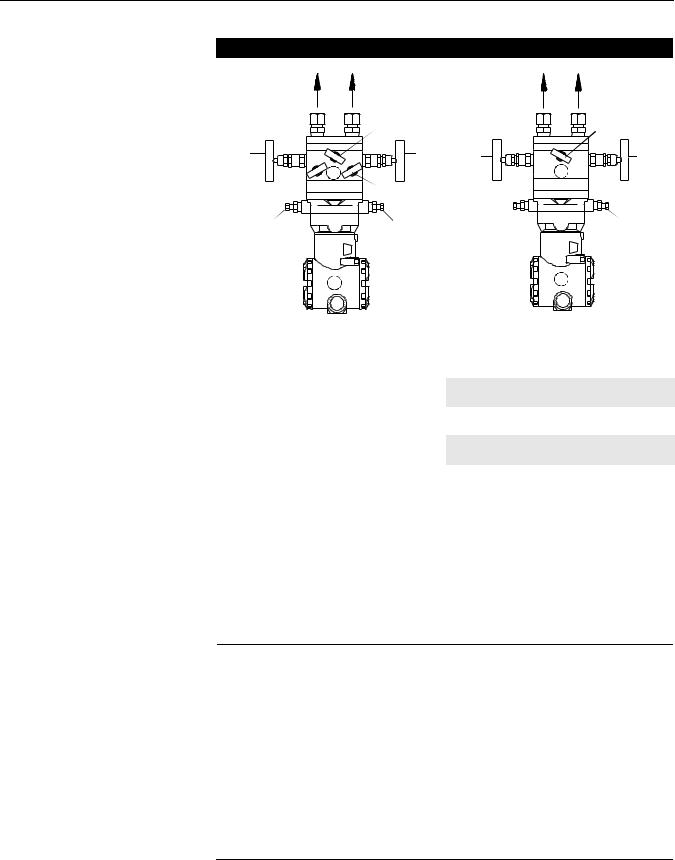
The integral mount flowmeter is usually shipped with the electronics bolted directly to the sensor. If this is not so, contact Rosemount Customer Central for more information.
Horizontal Pipes
Liquid or Steam Applications
Due to the possibility of air getting trapped in the probe, the sensor should be located according to Figure 2-5 for liquid or steam applications. The area between 0° and 30° angle should not be used unless full bleeding of air from the probe is possible.
For liquid applications, mount the side drain/vent valve upward to allow the gases to vent.
In steam applications, fill the lines with water to prevent the steam from contacting the electronics. Condensate chambers are not required because the volumetric displacement of the electronics is negligible.
Air and Gas Applications
Figure 2-5 illustrates the recommended location of the flowmeter in air or gas applications. The sensor should be located on the upper half of the pipe, at least 30° above the horizontal line.
For air and gas applications, mount the drain/vent valve downward to allow liquid to drain.
Figure 2-5. Horizontal Pipe
Applications
Liquid or Steam Applications |
Air or Gas Applications |
|
||
30 |
30 |
|
Recommended |
909A01A |
degrees |
degrees |
|
||
|
|
|
||
|
120 degrees |
30 |
Zone 120 |
909A02A, |
|
30 |
|||
|
|
|
degrees |
|
|
Recommended |
degrees |
degrees |
- |
|
Zone |
|
|
490000-9 |
|
|
|
|
|
Vertical Pipes
Liquid, Steam, Air, and Gas Applications
Figure 2-6 illustrates the recommended location of the flowmeter in liquid, air, or gas applications.
The sensor can be installed in any position around the circumference of the pipe, provided the vents are positioned properly for bleeding or venting. Vertical pipe installations require more frequent bleeding or venting, depending on the location.
2-8
Reference Manual
00809-0100-4809, Rev AA
August 2002
Annubar Flowmeter Series
Figure 2-6. Vertical Pipe |
Liquid or Steam Applications |
Air or Gas Applications |
|
Applications |
|||
|
|
||
|
|
Flow |
|
|
360 |
|
|
|
degrees |
|
Flow
360 degrees
Remote Mount
Instrument head connections differ between horizontal and vertical pipes. Consult your specification head code number to confirm the proper pipe orientation.
Valves and Fittings
Throughout the remote mounting process:
•Use only valves, fittings, and pipe thread sealant compounds that are rated for the service pipeline design pressure and temperature as specified in Appendix A: Specifications and Reference Data.
•Verify that all connections are tight and that all instrument valves are fully closed.
•Verify that the sensor probe is properly oriented for the intended type of service: liquid, gas or steam (see Figures “Integral (Direct) Mount” on page 2-8 and “Remote Mount” on page 2-9).
Impulse Piping
Impulse piping connects remote mounted electronics to the sensor. Temperatures in excess of 250 °F (121 °C) at the electronics will damage electronics components; impulse piping allows service flow temperatures to decrease to a point where the electronics is no longer vulnerable.
The following restrictions and recommendations apply to impulse piping location.
•Piping used to connect the sensor probe and electronics must be rated for continuous operation at the pipeline-designed pressure and temperature
•Impulse piping that runs horizontally must slope at least 1–in. per foot (83mm/m).
•It must slope downwards (toward the electronics) for liquid and steam applications.
•It must slope up (away from the electronics) for gas applications.
•For applications where the pipeline temperature is below 250 °F
(121 °C), the impulse piping should be as short as possible to minimize flow temperature changes. Insulation may be required.
2-9

Annubar Flowmeter Series
Reference Manual
00809-0100-4809, Rev AA
August 2002
•For applications where pipeline temperature is above 250 °F (121 °C), the impulse piping should have a minimum length of 1-ft. (0.30 m) for every 100 °F (38 °C) over 250 °F (121 °C), which is the maximum operating electronics temperature. Impulse piping must be uninsulated to reduce fluid temperature. All threaded connections should be checked after the system comes up to temperature, because connections may be loosened by the expansion and contraction caused by temperature changes.
•A minimum of 1/2-in. (12mm) outer diameter (OD) stainless steel tubing with a wall thickness of at least 0.035-in. is recommended.
•Outdoor installations for liquid, saturated gas, or steam service may require insulation and heat tracing to prevent freezing.
•For installations where the electronics are more than 6-ft. (1.8m) from the sensor probe, the high and low impulse piping must be run together to maintain equal temperature. They must be supported to prevent sagging and vibration.
•Threaded pipe fittings are not recommended because they create voids where air can become entrapped and have more possibilities for leakage.
•Run impulse piping in protected areas or against walls or ceilings. If the impulse piping is run across the floor, ensure that it is protected with coverings or kick plates. Do not locate the impulse piping near high temperature piping or equipment.
•Use an appropriate pipe sealing compound rated for the service
temperature on all threaded connections. When making threaded connections between stainless steel fittings, Loctite® PST® Sealant is recommended.
Figure 2-7. Liquid Service
Horizontal |
Vertical |
29-490000-941A01A, 942A01A
2-10

Reference Manual
00809-0100-4809, Rev AA
August 2002
Annubar Flowmeter Series
Figure 2-8. Gas Service
Horizontal |
Vertical |
29-490000-9
Figure 2-9. Steam Service
Horizontal |
Vertical |


 29-490000-980A02A, 981A01A
2-11

Annubar Flowmeter Series
Reference Manual
00809-0100-4809, Rev AA
August 2002
INSTALLATION |
This manual contains the horizontal and vertical installation procedures for |
|
the Pak-Lok, Flanged, Flange-Lok, and Threaded Flow-Tap Annubar models. |
Pak-Lok Model |
Figure 2-10 identifies the components of the Pak-Lok assembly. |
Figure 2-10. Components |
|
|
|
|
|
|
|
|
|
|
|
|
|
|
|
|
|
|
|
|
|
Transmitter |
|
|
|
|
|
|
|
|
|
|
|
|
|
|
|
|
|
|
|
||
|
|
|
|
|
|
|
|
|
|
|
|
|
|
|
|
|
|
|
|
Coplanar Flange with Drain |
|
|
|
|
|
|
|
|
|
|
|
|
|
|
|
|
|
|
|||
|
|
|
|
|
|
|
|
|
|
|
|
|
|
|
|
|
|
|
|
Vents |
Direct Mount Electronics |
|
|
|
|
||||||||||||||||
Connection with Valves |
|
|
|
O-Rings (2) |
||||||||||||||||
Nuts |
|
|
|
|
|
|
|
|
|
|
|
|
|
|
|
|
|
|
||
|
|
|
|
|
Compression Plate |
|||||||||||||||
|
|
|
|
|||||||||||||||||
Follower |
|
|
|
|
|
|
|
|
|
|
|
|
|
|
|
|||||
|
|
|
|
|
|
|
|
|
|
|
|
|
||||||||
|
|
|
|
|
|
|
||||||||||||||
|
|
|
|
|
|
|||||||||||||||
Packing Rings (3) |
|
|
|
|
|
|
|
|
Retaining Ring |
|||||||||||
|
|
|
|
|
|
|||||||||||||||
Studs |
|
|
|
|
|
|
|
|
|
|
|
|
|
|
|
|
|
|||
|
|
|
|
|
|
|
|
|
|
|
|
|
|
|
|
|||||
|
|
|
|
|
|
|
|
|
|
|
|
|
Pak-Lok Body |
|||||||
|
|
|
|
|
|
|
||||||||||||||
|
|
|
|
|
|
|
|
|
|
|
|
|
|
|
|
|
|
|
|
|
|
|
|
|
|
|
|
|
|
|
|
|
|
|
|
|
|
|
|
|
|
Opposites Side Support |
|
|
|
|
|
|
|
|
|
|
|
|
|
|
|
|
|
|
|
Annubar Sensor |
|
|
|
|
|
|
|
|
|
|
|
|
|
|
|
|
|
|
|||
|
|
|
|
|
|
|
|
|
|
|
|
|
|
|
|
|
||||
(optional) |
|
|
|
|
||||||||||||||||
28-49000-956A, 900A
Step 1: Set the Switches
Refer to “Mounting” on page 2-4 for more information
Step 2: Determine the Proper Orientation
Please refer to “Mounting” on page 2-4 for straight run requirements and orientation information.
Step 3: Drill a Hole into the Pipe
Follow the steps below to drill the hole in the pipe.
1.Depressurize and drain the pipe.
2.From the previous steps, select the location to drill the hole.
3.Determine the diameter of the hole to be drilled according to the specifications in Table 2-3 and drill the hole. Do not torch cut the hole.
2-12

Reference Manual
00809-0100-4809, Rev AA
August 2002
Annubar Flowmeter Series
Table 2-3. Drill Hole into Pipe |
|
|
|
|
Sensor Size / Hole Diameter Chart |
||||
|
||||
|
Sensor Diameter |
|
||
|
T1 |
3/4-in. |
+ 1/32-in (1 mm) |
|
|
(19 mm) |
– 0.00 |
||
|
|
|||
|
T2 |
15/16-in. |
+ 1/16-in. (1 mm) |
|
|
(34 mm) |
– 0.00 |
||
|
|
|||
|
T3 |
21/2-in. |
+ 1/16-in. (1 mm) |
|
|
(64 mm) |
– 0.00 |
||
|
|
|||
|
|
|
|
|
Note: Drill the hole 180 degrees from the first hole for opposite-side support models.
Drill the appropriate  diameter hole through the pipe wall.
8900-8900_15A
4.If opposite-side support coupling is supplied, a second identically sized hole must be drilled opposite the first hole so that the sensor can pass completely through the pipe. (To determine a opposite-side support model, measure the distance from the tip of the first slot or hole. If the distance is greater than 1-in. (25.4 mm), it is the opposite-side model.) To drill the second hole, follow these steps:
a.Measure the pipe circumference with a pipe tape, soft wire, or string (for the most accurate measurement the pipe tape needs to be perpendicular to the axis of flow).
b.Divide the measured circumference by two to determine the location of the second hole.
c.Rewrap the pipe tape, soft wire, or string from the center of the first hole. Then, using the number calculated in the preceding step, mark the center of what will become the second hole.
d.Using the diameter determined from Table 2-3, drill the hole into the pipe with a hole saw or drill. Do not torch cut the hole.
5.Deburr the drilled hole(s) on the inside of the pipe.
Step 4: Weld the Mounting Hardware
1.Center the Pak-Lok body over the mounting hole, gap 1/16-in. (1.5 mm) and place four 1/4-in. (6-mm) tack welds at 90° increments. Check alignment of the Pak-Lok body both parallel and perpendicular to the axis of flow. If alignment of mounting is within tolerances (see Figure 2-11), finish weld per local codes. If alignment is outside of specified tolerance make adjustments prior to finish weld.
2-13

Annubar Flowmeter Series
Reference Manual
00809-0100-4809, Rev AA
August 2002
Figure 2-11. Alignment
|
Tack |
|
LMH |
||
Welds |
||
|
28-490000_906A04A
2.If opposite side support is being used, center the fitting for the opposite
side support over the opposite side hole, gap 1/16-in. (1.5 mm) and place
four 1/4-in. (6 mm) tack welds at 90° increments. Insert the sensor into the mounting hardware. Verify that the tip of the bar is centered in the opposite side fitting and verify that the plug will fit around bar. If the bar is centered in the fitting and plug fits around the bar, finish weld per local codes. If the alignment of the bar does not allow enough clearance to insert the opposite side plug, make the necessary adjustments prior to making the finish weld.
NOTE
To avoid serious burns, allow the mounting hardware to cool before continuing.
Step 5: Insert into the Pipe
After the mounting hardware has cooled, use the following steps for installation.
1.Thread studs into the Pak-Lok body.
2.To ensure that the flowmeter contacts the opposite side wall, mark the
tip of the sensor with a marker. (Do not mark if the sensor was ordered with special-cleaned option code P2.)
3.Rotating the flowmeter back and forth, insert the flowmeter into the Pak-Lok body until the sensor tip contacts the pipe wall (or support plug).
4.Remove the flowmeter.
5.Verify that the sensor tip made contact with the pipe wall by removing the pipe and ensuring that some of the marker has been rubbed off. For special-cleaned bars, look for wear marks on the tip. If the tip did not touch the wall, verify pipe dimensions and the height of mounting body from the OD of the pipe and re-insert.
6.Re-insert the flowmeter into the Pak-Lok body and install the first packing ring on the sensor between the lock ring and the packing follower. Do not damage the split packing rings.
7.Push the packing ring into the Pak-Lok body and against the weld lock ring. Repeat this process for the two remaining rings, alternating the location of the packing ring split by 180°.
2-14

Reference Manual
00809-0100-4809, Rev AA
August 2002
Annubar Flowmeter Series
Figure 2-12. Packing Ring Detail |
Compression |
||
|
|
Plate |
|
|
Retaining |
||
|
Ring |
|
|
Follower
Packing
Ring
28-490000_942A01A
8.Tighten the nuts onto the studs:
•Place the included split-ring lock washer between each of the nuts and the compression plate. Give each nut one half (1/2) turn in succession until the split-ring lock washer is flat between the nut and the compression plate. Inspect the unit for leakage; if any exists, tighten the nuts in one-quarter (1/4) turn increments until there is no leakage.
NOTE
On sensor size (1), failure to use the split-ring lock washers, improper washer orientation, or over-tightening the nuts may result in damage to the flowmeter.
Figure 2-13. Split-Ring Lock |
|
Washer Orientation |
Stud |
|
Nut |
|
Split ring |
|
lock washer |
|
Compression |
|
Plate |
Before Tightening
After Tightening
Stud
Nut
Split ring lock washer
Compression Plate
28-490000_943A01A
NOTE
Pak-Lok sealing mechanisms generate significant force at the point where the sensor contacts the opposite pipe wall. Caution needs to be exercised on thin-walled piping (ANSI Schedule 10 and below) to avoid damage to the pipe.
Step 6: Mount the Transmitter
Direct Mount Head
With Valves
•Place Teflon (PTFE) O-rings into grooves on the face of head.
•Align the high side of the transmitter to the high side of the probe (“Hi” is stamped on the side of the head) and install.
•Tighten the nuts in a cross pattern to 400 in•lb (45 N•m).
2-15

Annubar Flowmeter Series
Reference Manual
00809-0100-4809, Rev AA
August 2002
Without Valves
•Place Teflon (PTFE) O-rings into grooves on the face of head.
•Orient the equalizer valve or valves so they are easily accessible. Install manifold with the smooth face mating to the face of the head. Tighten in cross pattern to a torque of 400 in•lb (45 N•m).
•Place Teflon (PTFE) O-rings into grooves on the face of the manifold.
•Align the high side of the transmitter to the high side of the probe (“Hi” is stamped on the side of the head) and install.
•Tighten the nuts in a cross pattern to 400 in•lb (45 N•m).
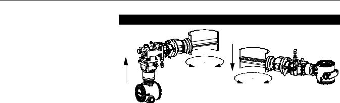
Remote Mount Head – temperatures below 250 °F (121 °C)
See “Remote Mount” on page 2-9 for more information.
Liquid Applications
Secure the electronics below the sensor to ensure that air will not be introduced into the impulse piping or the electronics.
Gas Applications
Secure the electronics above the sensor to prevent condensable liquids from collecting in the impulse piping and the DP cell.
28_490000_931A01A, 932A01A
Remote Mount Head – temperature above 250 °F (121 °C)
Liquid or Steam Applications
The electronics must be mounted below the process piping. Route the impulse piping down to the electronics and fill the system with cool water through the two tee fittings.
2-16
Loading...