


Reference Manual
00809-0100-4664, Rev BA
January 2010
Rosemount 8712
Remote Mount Magnetic Flowmeter System
www.rosemount.com

Reference Manual
00809-0100-4664, Rev BA
January 2010
Rosemount 8712
Remote Mount Magnetic
Flowmeter System
NOTICE
Read this manual before working with the product. For personal and system safety, and for optimum product performance, make sure you thoroughly understand the contents before installing, using, or maintaining this product.
Rosemount Inc. has two toll-free assistance numbers:
Customer Central
Technical support, quoting, and order-related questions. United States - 1-800-999-9307 (7:00 am to 7:00 pm CST) Asia Pacific65 777 8211
Europe/ Middle East/ Africa - 49 (8153) 9390
North American Response Center
Equipment service needs.
1-800-654-7768 (24 hours—includes Canada)
Outside of these areas, contact your local Emerson Process Management representative.
The products described in this document are NOT designed for nuclear-qualified applications. Using non-nuclear qualified products in applications that require nuclear-qualified hardware or products may cause inaccurate readings.
For information on Rosemount nuclear-qualified products, contact your local Emerson Process Management Sales Representative.
www.rosemount.com

Reference Manual
00809-0100-4664, Rev BA
January 2010
Rosemount 8732
SECTION 1
Introduction
SECTION 2
Installation
SECTION 3
Configuration
Table of Contents
System Description. . . . . . . . . . . . . . . . . . . . . . . . . . . . . . . . . . . . . . . 1-1
Safety Messages . . . . . . . . . . . . . . . . . . . . . . . . . . . . . . . . . . . . . . . . 1-2
Service Support . . . . . . . . . . . . . . . . . . . . . . . . . . . . . . . . . . . . . . . . . 1-2
Safety Messages . . . . . . . . . . . . . . . . . . . . . . . . . . . . . . . . . . . . . . . . 2-1 Transmitter Symbols. . . . . . . . . . . . . . . . . . . . . . . . . . . . . . . . . . . . . . 2-2 Pre-Installation . . . . . . . . . . . . . . . . . . . . . . . . . . . . . . . . . . . . . . . . . . 2-2 Mechanical Considerations . . . . . . . . . . . . . . . . . . . . . . . . . . . . . . 2-2 Environmental Considerations. . . . . . . . . . . . . . . . . . . . . . . . . . . . 2-4 Installation Procedures . . . . . . . . . . . . . . . . . . . . . . . . . . . . . . . . . . . . 2-4 Mount the Transmitter . . . . . . . . . . . . . . . . . . . . . . . . . . . . . . . . . . 2-4 Identify Options and Configurations . . . . . . . . . . . . . . . . . . . . . . . 2-4 Hardware Switches . . . . . . . . . . . . . . . . . . . . . . . . . . . . . . . . . . . . 2-4 Conduit Ports and Connections. . . . . . . . . . . . . . . . . . . . . . . . . . . 2-6 Conduit Cables . . . . . . . . . . . . . . . . . . . . . . . . . . . . . . . . . . . . . . . 2-6 Electrical Considerations . . . . . . . . . . . . . . . . . . . . . . . . . . . . . . . . 2-7 Installation Category . . . . . . . . . . . . . . . . . . . . . . . . . . . . . . . . . . . 2-9 Overcurrent Protection . . . . . . . . . . . . . . . . . . . . . . . . . . . . . . . . . 2-9 Options, Considerations, and Procedures . . . . . . . . . . . . . . . . . . . . . 2-9 Connect Transmitter Power. . . . . . . . . . . . . . . . . . . . . . . . . . . . . . 2-9 Connect 4–20 mA Loop External Power Source . . . . . . . . . . . . . . 2-9 Connect Pulse Output Power Source . . . . . . . . . . . . . . . . . . . . . 2-10 Connect Auxiliary Channel 1 . . . . . . . . . . . . . . . . . . . . . . . . . . . . 2-11 Connect Auxiliary Channel 2 . . . . . . . . . . . . . . . . . . . . . . . . . . . . 2-12 sensor Connections . . . . . . . . . . . . . . . . . . . . . . . . . . . . . . . . . . . . . 2-13 Rosemount Sensors . . . . . . . . . . . . . . . . . . . . . . . . . . . . . . . . . . 2-13 Transmitter to Sensor Wiring. . . . . . . . . . . . . . . . . . . . . . . . . . . . 2-13 Conduit Cables . . . . . . . . . . . . . . . . . . . . . . . . . . . . . . . . . . . . . . 2-14 Sensor to Remote Mount Transmitter Connections . . . . . . . . . . 2-15
Introduction. . . . . . . . . . . . . . . . . . . . . . . . . . . . . . . . . . . . . . . . . . . . . 3-1
Installation Check and Guide . . . . . . . . . . . . . . . . . . . . . . . . . . . . . . . 3-1
Local Operator Interface. . . . . . . . . . . . . . . . . . . . . . . . . . . . . . . . . . . 3-2
Basic Features . . . . . . . . . . . . . . . . . . . . . . . . . . . . . . . . . . . . . . . . . . 3-3
Data Entry . . . . . . . . . . . . . . . . . . . . . . . . . . . . . . . . . . . . . . . . . . . 3-3
Selecting Options . . . . . . . . . . . . . . . . . . . . . . . . . . . . . . . . . . . . . 3-4
LOI Examples . . . . . . . . . . . . . . . . . . . . . . . . . . . . . . . . . . . . . . . . . . . 3-4
Table Value Example . . . . . . . . . . . . . . . . . . . . . . . . . . . . . . . . . . 3-4
Select Value Example . . . . . . . . . . . . . . . . . . . . . . . . . . . . . . . . . . 3-4
Diagnostic Messages . . . . . . . . . . . . . . . . . . . . . . . . . . . . . . . . . . . . . 3-6
Review. . . . . . . . . . . . . . . . . . . . . . . . . . . . . . . . . . . . . . . . . . . . . . 3-6
Process Variables. . . . . . . . . . . . . . . . . . . . . . . . . . . . . . . . . . . . . . . . 3-6
PV - Primary Variable . . . . . . . . . . . . . . . . . . . . . . . . . . . . . . . . . . 3-7
PV -% Range. . . . . . . . . . . . . . . . . . . . . . . . . . . . . . . . . . . . . . . . . 3-7
PV - Analog Output . . . . . . . . . . . . . . . . . . . . . . . . . . . . . . . . . . . . 3-7
Totalizer Setup . . . . . . . . . . . . . . . . . . . . . . . . . . . . . . . . . . . . . . . 3-7
Pulse Output . . . . . . . . . . . . . . . . . . . . . . . . . . . . . . . . . . . . . . . . . 3-8
TOC-1

Reference Manual
00809-0100-4664, Rev BA
January 2010
Rosemount 8732
SECTION 4
Operation
Basic Setup. . . . . . . . . . . . . . . . . . . . . . . . . . . . . . . . . . . . . . . . . . . . . 3-8
Tag . . . . . . . . . . . . . . . . . . . . . . . . . . . . . . . . . . . . . . . . . . . . . . . . 3-8
Flow Units . . . . . . . . . . . . . . . . . . . . . . . . . . . . . . . . . . . . . . . . . . . 3-8
Line Size . . . . . . . . . . . . . . . . . . . . . . . . . . . . . . . . . . . . . . . . . . . 3-10
PV URV (Upper Range Value) . . . . . . . . . . . . . . . . . . . . . . . . . . 3-11
PV LRV (Lower Range Value). . . . . . . . . . . . . . . . . . . . . . . . . . . 3-11
Calibration Number . . . . . . . . . . . . . . . . . . . . . . . . . . . . . . . . . . . 3-12
PV Damping . . . . . . . . . . . . . . . . . . . . . . . . . . . . . . . . . . . . . . . . 3-12
Introduction. . . . . . . . . . . . . . . . . . . . . . . . . . . . . . . . . . . . . . . . . . . . . 4-1
Diagnostics . . . . . . . . . . . . . . . . . . . . . . . . . . . . . . . . . . . . . . . . . . . . . 4-1
Diagnostic Controls . . . . . . . . . . . . . . . . . . . . . . . . . . . . . . . . . . . . 4-1
Basic Diagnostics . . . . . . . . . . . . . . . . . . . . . . . . . . . . . . . . . . . . . 4-2
Advanced Diagnostics . . . . . . . . . . . . . . . . . . . . . . . . . . . . . . . . . . 4-7
Diagnostic Variable Values . . . . . . . . . . . . . . . . . . . . . . . . . . . . . 4-12
Trims . . . . . . . . . . . . . . . . . . . . . . . . . . . . . . . . . . . . . . . . . . . . . . 4-14
Status . . . . . . . . . . . . . . . . . . . . . . . . . . . . . . . . . . . . . . . . . . . . . 4-16
Advanced Configuration . . . . . . . . . . . . . . . . . . . . . . . . . . . . . . . . . . 4-16
Detailed Setup . . . . . . . . . . . . . . . . . . . . . . . . . . . . . . . . . . . . . . . . . 4-16
Additional Parameters . . . . . . . . . . . . . . . . . . . . . . . . . . . . . . . . . 4-16
Configure Outputs . . . . . . . . . . . . . . . . . . . . . . . . . . . . . . . . . . . . 4-17
LOI Configuration . . . . . . . . . . . . . . . . . . . . . . . . . . . . . . . . . . . . 4-31
Signal Processing . . . . . . . . . . . . . . . . . . . . . . . . . . . . . . . . . . . . 4-31
Universal Auto Trim . . . . . . . . . . . . . . . . . . . . . . . . . . . . . . . . . . . 4-34
Device Info. . . . . . . . . . . . . . . . . . . . . . . . . . . . . . . . . . . . . . . . . . 4-34
SECTION 5
Sensor Installation
Safety Messages . . . . . . . . . . . . . . . . . . . . . . . . . . . . . . . . . . . . . . . . 5-1
Sensor Handling . . . . . . . . . . . . . . . . . . . . . . . . . . . . . . . . . . . . . . . . . 5-3
Sensor Mounting. . . . . . . . . . . . . . . . . . . . . . . . . . . . . . . . . . . . . . . . . 5-4
Upstream/Downstream Piping. . . . . . . . . . . . . . . . . . . . . . . . . . . . 5-4
Sensor Orientation. . . . . . . . . . . . . . . . . . . . . . . . . . . . . . . . . . . . . 5-4
Flow Direction . . . . . . . . . . . . . . . . . . . . . . . . . . . . . . . . . . . . . . . . 5-6
Installation (Flanged Sensor) . . . . . . . . . . . . . . . . . . . . . . . . . . . . . . . 5-7
Gaskets . . . . . . . . . . . . . . . . . . . . . . . . . . . . . . . . . . . . . . . . . . . . . 5-7
Flange Bolts. . . . . . . . . . . . . . . . . . . . . . . . . . . . . . . . . . . . . . . . . . 5-7
Installation (Wafer Sensor) . . . . . . . . . . . . . . . . . . . . . . . . . . . . . . . . 5-10
Gaskets . . . . . . . . . . . . . . . . . . . . . . . . . . . . . . . . . . . . . . . . . . . . 5-10
Flange Bolts. . . . . . . . . . . . . . . . . . . . . . . . . . . . . . . . . . . . . . . . . 5-11
Installation (Sanitary Sensor) . . . . . . . . . . . . . . . . . . . . . . . . . . . . . . 5-12
Gaskets . . . . . . . . . . . . . . . . . . . . . . . . . . . . . . . . . . . . . . . . . . . . 5-12
Alignment and Bolting . . . . . . . . . . . . . . . . . . . . . . . . . . . . . . . . . 5-12
Grounding. . . . . . . . . . . . . . . . . . . . . . . . . . . . . . . . . . . . . . . . . . . . . 5-12
Process Leak Protection (Optional) . . . . . . . . . . . . . . . . . . . . . . . . . 5-15
Standard Housing Configuration . . . . . . . . . . . . . . . . . . . . . . . . . 5-15
Relief Valves . . . . . . . . . . . . . . . . . . . . . . . . . . . . . . . . . . . . . . . . 5-16
Process Leak Containment . . . . . . . . . . . . . . . . . . . . . . . . . . . . . 5-17
TOC-2

Reference Manual
00809-0100-4664, Rev BA
January 2010
Rosemount 8732
SECTION 6
Maintenance and
Troubleshooting
APPENDIX A
Reference Data
APPENDIX B
Approval
Information
APPENDIX C
Diagnostics
APPENDIX D
Digital Signal
Processing
Safety Information. . . . . . . . . . . . . . . . . . . . . . . . . . . . . . . . . . . . . . . . 6-1
Installation Check and Guide . . . . . . . . . . . . . . . . . . . . . . . . . . . . . . . 6-2
Diagnostic Messages . . . . . . . . . . . . . . . . . . . . . . . . . . . . . . . . . . . . . 6-3
Transmitter Troubleshooting. . . . . . . . . . . . . . . . . . . . . . . . . . . . . . . . 6-6
Quick Troubleshooting . . . . . . . . . . . . . . . . . . . . . . . . . . . . . . . . . . . . 6-8
Step 1: Wiring Errors . . . . . . . . . . . . . . . . . . . . . . . . . . . . . . . . . . . 6-8
Step 2: Process Noise . . . . . . . . . . . . . . . . . . . . . . . . . . . . . . . . . . 6-8
Step 3: Installed Sensor Tests. . . . . . . . . . . . . . . . . . . . . . . . . . . . 6-8
Step 4: Uninstalled Sensor Tests . . . . . . . . . . . . . . . . . . . . . . . . 6-10
Functional Specifications . . . . . . . . . . . . . . . . . . . . . . . . . . . . . . . . . . A-1
Performance Specifications . . . . . . . . . . . . . . . . . . . . . . . . . . . . . . . . A-6
Physical Specifications . . . . . . . . . . . . . . . . . . . . . . . . . . . . . . . . . . . . A-8
Rosemount 8712E Ordering Information . . . . . . . . . . . . . . . . . . . . . . A-9
Product Certifications . . . . . . . . . . . . . . . . . . . . . . . . . . . . . . . . . . . . . B-1
Approved Manufacturing Locations . . . . . . . . . . . . . . . . . . . . . . . . . . B-1
European Directive Information . . . . . . . . . . . . . . . . . . . . . . . . . . . B-1
Hazardous Locations Certifications . . . . . . . . . . . . . . . . . . . . . . . . B-1
Sensor Approval Information . . . . . . . . . . . . . . . . . . . . . . . . . . . . . B-2
Diagnostic Availability . . . . . . . . . . . . . . . . . . . . . . . . . . . . . . . . . . . . . C-1
Licensing and Enabling. . . . . . . . . . . . . . . . . . . . . . . . . . . . . . . . . . . . C-2
Licensing the 8712 Diagnostics. . . . . . . . . . . . . . . . . . . . . . . . . . . C-2
Tunable Empty Pipe Detection . . . . . . . . . . . . . . . . . . . . . . . . . . . . . . C-2
Tunable Empty Pipe Parameters. . . . . . . . . . . . . . . . . . . . . . . . . . C-3
Optimizing Tunable Empty Pipe . . . . . . . . . . . . . . . . . . . . . . . . . . C-3
Troubleshooting Empty Pipe . . . . . . . . . . . . . . . . . . . . . . . . . . . . . C-4
Ground/Wiring Fault Detection . . . . . . . . . . . . . . . . . . . . . . . . . . . . . . C-4
Ground/Wiring Fault Parameters. . . . . . . . . . . . . . . . . . . . . . . . . . C-4
Troubleshooting Ground/Wiring Fault . . . . . . . . . . . . . . . . . . . . . . C-5
Ground/Wiring Fault Functionality . . . . . . . . . . . . . . . . . . . . . . . . . C-5
High Process Noise Detection . . . . . . . . . . . . . . . . . . . . . . . . . . . . . . C-5
High Process Noise Parameters . . . . . . . . . . . . . . . . . . . . . . . . . . C-6
Troubleshooting High Process Noise . . . . . . . . . . . . . . . . . . . . . . C-6
High Process Noise Functionality . . . . . . . . . . . . . . . . . . . . . . . . . C-7
8714i Meter Verification . . . . . . . . . . . . . . . . . . . . . . . . . . . . . . . . . . . C-8
Sensor Signature Parameters . . . . . . . . . . . . . . . . . . . . . . . . . . . . C-8
8714i Meter Verification Test Parameters . . . . . . . . . . . . . . . . . . . C-9
8714i Meter Verification Test Results Parameters . . . . . . . . . . . C-10
Optimizing the 8714i Meter Verification. . . . . . . . . . . . . . . . . . . . C-13
Troubleshooting the 8714i Meter Verification Test . . . . . . . . . . . C-14
8714i Meter Verification Functionality . . . . . . . . . . . . . . . . . . . . . C-14
Rosemount Magnetic Flowmeter Calibration Verification Report . . . C-16
Safety Messages . . . . . . . . . . . . . . . . . . . . . . . . . . . . . . . . . . . . . . . . D-1
Warnings . . . . . . . . . . . . . . . . . . . . . . . . . . . . . . . . . . . . . . . . . . . . D-1
Procedures . . . . . . . . . . . . . . . . . . . . . . . . . . . . . . . . . . . . . . . . . . . . . D-2
Auto Zero. . . . . . . . . . . . . . . . . . . . . . . . . . . . . . . . . . . . . . . . . . . . D-2
Signal Processing . . . . . . . . . . . . . . . . . . . . . . . . . . . . . . . . . . . . . D-2
TOC-3

Reference Manual
00809-0100-4664, Rev BA
January 2010
Rosemount 8732
APPENDIX E
Universal Sensor
Wiring Diagrams
APPENDIX F
HART Field
Communicator
Operation
Rosemount Sensors . . . . . . . . . . . . . . . . . . . . . . . . . . . . . . . . . . . . . . E-3
ABB Sensors . . . . . . . . . . . . . . . . . . . . . . . . . . . . . . . . . . . . . . . . . . . E-7
Brooks Sensors . . . . . . . . . . . . . . . . . . . . . . . . . . . . . . . . . . . . . . . . . E-9
Endress And Hauser Sensors . . . . . . . . . . . . . . . . . . . . . . . . . . . . . E-11
Fischer And Porter Sensors . . . . . . . . . . . . . . . . . . . . . . . . . . . . . . . E-15
Foxboro Sensors . . . . . . . . . . . . . . . . . . . . . . . . . . . . . . . . . . . . . . . E-22
Kent Sensors . . . . . . . . . . . . . . . . . . . . . . . . . . . . . . . . . . . . . . . . . . E-28
Krohne Sensors . . . . . . . . . . . . . . . . . . . . . . . . . . . . . . . . . . . . . . . . E-30
Siemens Sensors . . . . . . . . . . . . . . . . . . . . . . . . . . . . . . . . . . . . . . . E-33
Taylor Sensors . . . . . . . . . . . . . . . . . . . . . . . . . . . . . . . . . . . . . . . . . E-34
Toshiba Sensors. . . . . . . . . . . . . . . . . . . . . . . . . . . . . . . . . . . . . . . . E-36
Yamatake Honeywell Sensors . . . . . . . . . . . . . . . . . . . . . . . . . . . . . E-37
Yokogawa Sensors. . . . . . . . . . . . . . . . . . . . . . . . . . . . . . . . . . . . . . E-38
Generic Manufacturer Sensors. . . . . . . . . . . . . . . . . . . . . . . . . . . . . E-39
HandHeld Communicator . . . . . . . . . . . . . . . . . . . . . . . . . . . . . . . . . . F-1
Connections and Hardware . . . . . . . . . . . . . . . . . . . . . . . . . . . . . . . . F-2
Basic Features . . . . . . . . . . . . . . . . . . . . . . . . . . . . . . . . . . . . . . . . . . F-3
Action Keys . . . . . . . . . . . . . . . . . . . . . . . . . . . . . . . . . . . . . . . . . . F-3
Alphanumeric and Shift Keys . . . . . . . . . . . . . . . . . . . . . . . . . . . . F-4
Fast Key Feature . . . . . . . . . . . . . . . . . . . . . . . . . . . . . . . . . . . . . . F-5
Menus and Functions . . . . . . . . . . . . . . . . . . . . . . . . . . . . . . . . . . . . . F-5
Main Menu. . . . . . . . . . . . . . . . . . . . . . . . . . . . . . . . . . . . . . . . . . . F-5
Online Menu . . . . . . . . . . . . . . . . . . . . . . . . . . . . . . . . . . . . . . . . . F-6
Diagnostic Messages . . . . . . . . . . . . . . . . . . . . . . . . . . . . . . . . . . F-7
TOC-4

Reference Manual
00809-0100-4664, Rev BA
January 2010
Rosemount 8712
Section 1 |
Introduction |
SYSTEM DESCRIPTION
System Description . . . . . . . . . . . . . . . . . . . . . . . . . . . . . . page 1-1 Safety Messages . . . . . . . . . . . . . . . . . . . . . . . . . . . . . . . . . page 1-2 Service Support . . . . . . . . . . . . . . . . . . . . . . . . . . . . . . . . . page 1-2
The Rosemount® 8700 Series Magnetic Flowmeter System consists of a sensor and transmitter, and measures volumetric flow rate by detecting the velocity of a conductive liquid that passes through a magnetic field.
There are four Rosemount magnetic flowmeter sensors:
•Flanged Rosemount 8705
•Flanged High-Signal Rosemount 8707
•Wafer-Style Rosemount 8711
•Sanitary Rosemount 8721
There are two Rosemount magnetic flowmeter transmitters:
•Rosemount 8712
•Rosemount 8732
The sensor is installed in-line with process piping — either vertically or horizontally. Coils located on opposite sides of the sensor create a magnetic field. Electrodes located perpendicular to the coils make contact with the process fluid. A conductive liquid moving through the magnetic field generates a voltage at the two electrodes that is proportional to the flow velocity.
The transmitter drives the coils to generate a magnetic field, and electronically conditions the voltage detected by the electrodes to provide a flow signal. The transmitter can be integrally or remotely mounted from the sensor.
This manual is designed to assist in the installation and operation of the Rosemount 8712 Magnetic Flowmeter Transmitter and the Rosemount 8700 Series Magnetic Flowmeter Sensors.
www.rosemount.com

Rosemount 8712
Reference Manual
00809-0100-4664, Rev BA
January 2010
SAFETY MESSAGES
Procedures and instructions in this manual may require special precautions to ensure the safety of the personnel performing the operations. Refer to the safety messages listed at the beginning of each section before performing any operations.
Attempting to install and operate the Rosemount 8705, Rosemount 8707 High-Signal, Rosemount 8711, or Rosemount 8721 Magnetic Sensors with the Rosemount 8712 or Rosemount 8732 Magnetic Flowmeter Transmitter without reviewing the instructions contained in this manual could result in personal injury or equipment damage.
SERVICE SUPPORT
To expedite the return process outside the United States, contact the nearest Rosemount representative.
Within the United States and Canada, call the North American Response Center using the 800-654-RSMT (7768) toll-free number. The Response Center, available 24 hours a day, will assist you with any needed information or materials.
The center will ask for product model and serial numbers, and will provide a Return Material Authorization (RMA) number. The center will also ask for the name of the process material to which the product was last exposed.
Mishandling products exposed to a hazardous substance may result in death or serious injury. If the product being returned was exposed to a hazardous substance as defined by OSHA, a copy of the required Material Safety Data Sheet (MSDS) for each hazardous substance identified must be included with the returned goods.
The North American Response Center will detail the additional information and procedures necessary to return goods exposed to hazardous substances.
See “Safety Messages” on page D-1 for complete warning information.
1-2
Reference Manual
00809-0100-4664, Rev BA
January 2010
Rosemount 8712
Section 2 |
Installation |
SAFETY MESSAGES
Safety Messages . . . . . . . . . . . . . . . . . . . . . . . . . . . . . . . . . page 2-1 Transmitter Symbols . . . . . . . . . . . . . . . . . . . . . . . . . . . . . page 2-2 Pre-Installation . . . . . . . . . . . . . . . . . . . . . . . . . . . . . . . . . . page 2-2 Installation Procedures . . . . . . . . . . . . . . . . . . . . . . . . . . . page 2-4 Options, Considerations, and Procedures . . . . . . . . . . . . page 2-9 sensor Connections . . . . . . . . . . . . . . . . . . . . . . . . . . . . . . page 2-13
This section covers the steps required to physically install the magnetic flowmeter. Instructions and procedures in this section may require special precautions to ensure the safety of the personnel performing the operations. Please refer to the following safety messages before performing any operation in this section.
This symbol is used throughout this manual to indicate that special attention to warning information is required.
Instructions and procedures in this section may require special precautions to ensure the safety of the personnel performing the operations. Please refer to the following safety messages before performing any operation in this section.
Failure to follow these installation guidelines could result in death or serious injury:
Installation and servicing instructions are for use by qualified personnel only. Do not perform any servicing other than that contained in the operating instructions, unless qualified. Verify that the operating environment of the sensor and transmitter is consistent with the appropriate hazardous area approval.
Do not connect a Rosemount 8712 to a non-Rosemount sensor that is located in an explosive atmosphere.
www.rosemount.com
Rosemount 8712
Reference Manual
00809-0100-4664, Rev BA
January 2010
Explosions could result in death or serious injury:
Installation of this transmitter in an explosive environment must be in accordance with the appropriate local, national, and international standards, codes, and practices. Please review the approvals section of the 8712 reference manual for any restrictions associated with a safe installation.
Before connecting a handheld communicator in an explosive atmosphere, make sure the instruments in the loop are installed in accordance with intrinsically safe or non-incendive field wiring practices.
Electrical shock can result in death or serious injury
Avoid contact with the leads and terminals. High voltage that may be present on leads can cause electrical shock.
The sensor liner is vulnerable to handling damage. Never place anything through the sensor for the purpose of lifting or gaining leverage. Liner damage can render the sensor useless.
To avoid possible damage to the sensor liner ends, do not use metallic or spiral-wound gaskets. If frequent removal is anticipated, take precautions to protect the liner ends. Short spool pieces attached to the sensor ends are often used for protection.
Correct flange bolt tightening is crucial for proper sensor operation and life. All bolts must be tightened in the proper sequence to the specified torque limits. Failure to observe these instructions could result in severe damage to the sensor lining and possible sensor replacement.
TRANSMITTER
SYMBOLS
PRE-INSTALLATION
Caution symbol — check product documentation for details  Protective conductor (grounding) terminal
Before installing the Rosemount 8712 Magnetic Flowmeter Transmitter, there are several pre-installation steps that should be completed to make the installation process easier:
•Identify the options and configurations that apply to your application
•Set the hardware switches if necessary
•Consider mechanical, electrical, and environmental requirements
Mechanical |
The mounting site for the Rosemount 8712 transmitter should provide enough |
Considerations |
room for secure mounting, easy access to conduit ports, full opening of the |
|
transmitter covers, and easy readability of the LOI screen (see Figure 2-1). |
|
The transmitter should be mounted in a manner that prevents moisture in the |
|
conduit from collecting in the transmitter. |
|
The 8712 is mounted separately from the sensor, it |
|
is not subject to limitations that might apply to the sensor. |
2-2

Reference Manual
00809-0100-4664, Rev BA
January 2010
Rosemount 8712
Figure 2-1. Rosemount 8712
Dimensional Drawing
|
WITH STANDARD COVER |
|
|
4.31 |
9.01 |
|
|
(109) |
(229) |
|
0.44 |
|
2.81 |
3.11 |
|
|
(71) |
(79) |
(11) |
|
|
|
12.02 |
|
|
|
(305) |
|
|
|
11.15 |
|
|
|
(283) |
2.96 |
|
|
|
(75) |
|
WITH LOI COVER |
|
|
|
||
|
1/2–14 NPT |
|
Ground Lug |
Conduit |
LOI Keypad |
Connection |
||
|
(4 Places) |
Cover |
NOTE
Dimensions are in inches (millimeters)
2-3

Rosemount 8712
Reference Manual
00809-0100-4664, Rev BA
January 2010
Environmental |
To ensure maximum transmitter life, avoid excessive heat and vibration. |
|
Considerations |
Typical problem areas: |
|
|
• high-vibration lines with integrally mounted transmitters |
|
|
• |
warm-climate installations in direct sunlight |
|
• |
outdoor installations in cold climates. |
INSTALLATION
PROCEDURES Mount the Transmitter
Identify Options and
Configurations
Remote-mounted transmitters may be installed in the control room to protect the electronics from the harsh environment and provides easy access for configuration or service.
Rosemount 8712 transmitters require external power and there must be access to a suitable power source.
Rosemount 8712 installation includes both detailed mechanical and electrical installation procedures.
At a remote site the transmitter may be mounted on a pipe up to two inches in diameter or against a flat surface.
Pipe Mounting
To mount the transmitter on a pipe:
1.Attach the mounting plate to the pipe using the mounting hardware.
2.Attach the 8712 to the mounting plate using the mounting screws.
Surface Mounting
To surface mount the transmitter:
1.Attach the 8712 to the mounting location using the mounting screws.
The standard application of the 8712 includes a 4–20 mA output and control of the sensor coils. Other applications may require one or more of the following configurations or options:
•Multidrop Communications
•PZR (Positive Zero Return)
•Auxiliary Output
•Pulse Output
Hardware Switches
Additional options may apply. Be sure to identify those options and configurations that apply to your situation, and keep a list of them nearby for consideration during the installation and configuration procedures.
The 8712 electronics board is equipped with
three user-selectable hardware switches. These switches set the Failure Alarm Mode, Internal/External Analog Power, and Transmitter Security. The standard configuration for these switches when shipped from the factory are as follows:
Failure Alarm Mode: |
HIGH |
Internal/External Analog Power: |
INTERNAL |
Transmitter Security: |
OFF |
2-4

Reference Manual
00809-0100-4664, Rev BA
January 2010
Rosemount 8712
Changing Hardware Switch Settings
In most cases, it is not necessary to change the setting of the hardware switches. If you need to change the switch settings, complete the steps outlined in the manual.
Definitions of these switches and their functions are provided below. If you determine that the settings must be changed, see below.
Failure Alarm Mode
If the 8712 experiences a catastrophic failure in the electronics, the current output can be driven high (23.25 mA) or low (3.75 mA). The switch is set in the HIGH (23.25 mA) position when it is shipped from the factory.
Internal/External Analog Power
The Rosemount 8712 4–20 mA loop may be powered internally
or by an external power supply. The internal/external power supply switch determines the source of the 4–20 mA loop power.
Transmitters are shipped from the factory with the switch set in the INTERNAL position.
The external power option is required for multidrop configurations. A 10–30 V DC external supply is required and the 4-20mA power switch must be set to “EXT” position. For further information on 4–20 mA external power, see Connect 4–20 mA Loop External Power Source on page 2-9.
Transmitter Security
The security switch on the 8712 allows the user to lock out any configuration changes attempted on the transmitter. No changes to the configuration are allowed when the switch is in the ON position. The flow rate indication and totalizer functions remain active at all times.
With the switch in the ON position, you may still access and review any of the operating parameters and scroll through the available choices, but no actual data changes are allowed. Transmitter security is set in the OFF position when shipped from factory.
Changing Hardware Switch Settings
In most cases, it is not necessary to change the setting of the hardware switches. If you need to change the switch settings, complete the steps below:
NOTE
The hardware switches are located on the non-component side of the electronics board and changing their settings requires opening the electronics housing. If possible, carry out these procedures away from the plant environment in order to protect the electronics.
1.Disconnect power to the transmitter.
2.Loosen the housing door screw and open the housing door.
3.Identify the location of each switch (see Figure 2-2).
4.Change the setting of the desired switches with a small screwdriver.
5.Close the housing door and tighten the housing door screw.
2-5
Rosemount 8712
Reference Manual
00809-0100-4664, Rev BA
January 2010
Figure 2-2. Rosemount 8712
Electronics Board and Hardware
Switches
Conduit Ports
and Connections
Conduit Cables
Both the sensor and transmitter junction boxes have ports for 1/2-in. NPT conduit connections. These connections should be made in accordance with local or plant electrical codes. Unused ports should be sealed with metal plugs. Proper electrical installation is necessary to prevent errors due to electrical noise and interference. Separate conduits are not necessary for the two cables, but a dedicated conduit line between each transmitter and sensor is required. Shielded cable must be used for best results in electrically
noisy environments.
Example 1: Installing flanged sensors into an IP68 area. Sensors must be installed with IP68 cable glands and cable to maintain IP68 rating. Unused conduit connections must be properly sealed to prevent water ingress. For added protection, dielectric gel can be used to pot the sensor terminal block.
Example 2: Installing flowmeters into explosion proof/flameproof areas. Conduit connections and conduit must be rated for use in the hazardous area to maintain flowmeter approval rating.
Run the appropriate size cable through the conduit connections in your magnetic flowmeter system. Run the power cable from the power source to the transmitter. Run the coil drive and electrode cables between the flowmeter and transmitter. Refer to Electrical Considerations for wire type. Prepare the ends of the coil drive and electrode cables as shown in Figure 2-3. Limit the unshielded wire length to 1-inch on both the electrode and coil drive cables. Excessive lead length or failure to connect cable shields can create electrical noise resulting in unstable meter readings.
•Installed signal wiring should not be run together and should not be in the same cable tray as AC or DC power wiring.
•Device must be properly grounded or earthed according to local electric codes.
•Rosemount combination cable model number 08712-0752-0001 (ft) or 08712-0752-0003 (m) is required to be used to meet EMC requirements.
2-6
Reference Manual
00809-0100-4664, Rev BA
January 2010
Rosemount 8712
Figure 2-3. Cable Preparation
Detail 1.00
(26)
|
NOTE |
|
Dimensions are in |
|
inches |
Cable Shield |
(millimeters). |
Electrical Considerations Before making any electrical connections to the Rosemount 8712, consider the following standards and be sure to have the proper power supply, conduit, and other accessories.
Transmitter Input Power
The 8712 transmitter is designed to be powered by 90-250 V AC, 50–60 Hz or 12–42 V DC. The eight digit in the transmitter model number designates the appropriate power supply requirement.
Model Number |
Power Supply Requirement |
|
|
2 |
12-42 V DC |
1 |
90-250 V AC |
Supply Wire Temperature Rating
Use 12 to 18 AWG wire. For connections in ambient temperatures exceeding 140 °F (60 °C), use wire rated to at least 194 °F (90 °C).
Disconnects
Connect the device through an external disconnect or circuit breaker. Clearly label the disconnect or circuit breaker and locate it near the transmitter.
Requirements for 90-250 V AC Power Supply
Wire the transmitter according to local electrical requirements for the supply voltage. In addition, follow the supply wire and disconnect requirements on page 2-9.
Requirements for 12-42 V DC Power Supply
Units powered with 12-42 V DC may draw up to 1 amp of current. As a result, the input power wire must meet certain gauge requirements.
Figure 2-4 shows the surge current for each corresponding supply voltage. For combinations not shown, you can calculate the maximum distance given the supply current, the voltage of the source, and the minimum start-up voltage of the transmitter, 12 V DC, using the following equation:
Supply Voltage–12VDC Maximum Resis tance = ------------------------------------------------------------------------
1 amp
Use Table 2-1 and Table 2-2 to determine the maximum wire length allowable for your power supply and maximum resistance.
2-7
Rosemount 8712
Reference Manual
00809-0100-4664, Rev BA
January 2010
Table 2-1. Length of Annealed
Copper (cu) Wires |
Types of Power |
Maximum Length of the Wire for Each |
||||
|
Supply Wires |
Corresponding Power Supply Source |
||||
|
Wire |
Annealed Cu |
42 V DC |
30 V DC |
20 V DC |
12.5 V DC |
|
Gauge |
milliohms/ft |
Supply ft (m) |
Supply ft (m) |
Supply ft (m) |
Supply ft (m) |
|
|
(milliohms/m) |
|
|
|
|
|
20 |
0.01015 |
1478 |
887 |
394 |
25 |
|
|
(0.033292) |
(451) |
(270) |
(120) |
(8) |
|
18 |
0.006385 |
2349 |
1410 |
626 |
39 |
|
|
(0.020943) |
(716) |
(430) |
(191) |
(12) |
|
16 |
0.004016 |
3735 |
2241 |
996 |
62 |
|
|
(0.013172) |
(1139) |
(683) |
(304) |
(19) |
|
14 |
0.002525 |
5941 |
3564 |
1584 |
99 |
|
|
(0.008282) |
(1811) |
(1087) |
(483) |
(30) |
|
12 |
0.001588 |
9446 |
5668 |
2519 |
157 |
|
|
(0.005209) |
(2880) |
(1728) |
(768) |
(48) |
|
10 |
0.000999 |
15015 |
9009 |
4004 |
250 |
|
|
(0.003277) |
(4578) |
(2747) |
(1221) |
(76) |
Table 2-2. Length of
Hand-drawn Copper (cu) Wires
Figure 2-4. Supply Current versus Input Voltage
Types of Power |
|
Maximum Length of the Wire for |
|
|||
Supply Wires |
Each Corresponding Power Supply Source |
|||||
|
|
|
|
|
|
|
Wire |
Annealed Cu |
42 V DC |
30 V DC |
20 V DC |
|
12.5 V DC |
Gauge |
milliohms/ft |
Supply ft (m) |
Supply ft (m) |
Supply ft (m) |
|
Supply ft (m) |
|
(milliohms/m) |
|
|
|
|
|
18 |
0.00664 |
2259 |
1355 |
602 |
|
38 |
|
(0.021779) |
(689) |
(413) |
(184) |
|
(11) |
16 |
0.004176 |
3592 |
2155 |
958 |
|
60 |
|
(0.013697) |
(1095) |
(657) |
(292) |
|
(18) |
14 |
0.002626 |
5712 |
3427 |
1523 |
|
95 |
|
(0.008613) |
(1741) |
(1045) |
(464) |
|
(29) |
12 |
0.001652 |
9080 |
5448 |
2421 |
|
151 |
|
(0.005419) |
(2768) |
(1661) |
(738) |
|
(46) |
10 |
0.01039 |
14437 |
8662 |
3850 |
|
241 |
|
(0.003408) |
(4402) |
(2641) |
(1174) |
|
(73) |
|
1.0 |
|
|
|
|
|
|
0.8 |
|
|
|
|
|
(Amps) |
0.6 |
|
|
|
|
|
|
|
|
|
|
|
|
Supply Current |
0.4 |
|
|
|
|
|
0.2 |
|
|
|
|
|
|
|
0 |
|
|
|
|
|
|
0 |
10 |
20 |
30 |
40 |
50 |
Power Supply (Volts)
2-8
Reference Manual
00809-0100-4664, Rev BA
January 2010
Rosemount 8712
Installation Category
The installation category for the Rosemount 8712 is (Overvoltage) Category II.
Overcurrent Protection
The Rosemount 8712 Flowmeter Transmitter requires overcurrent protection of the supply lines. Maximum ratings of overcurrent devices are as follows:
Power System |
Fuse Rating |
Manufacturer |
|
|
|
90–250 V AC |
2 Amp, Quick Acting |
Bussman AGCI or Equivalent |
|
|
|
12-42 V DC |
3 Amp, Quick Acting |
Bussman AGC3 or Equivalent |
|
|
|
OPTIONS, CONSIDERATIONS, AND PROCEDURES
Connect Transmitter
Power
If the application of the 8712 includes the use of options such as multidrop communications, auxiliary output control, or pulse output, certain requirements may apply in addition to those previously listed. Be prepared to meet these requirements before attempting to install and operate the Rosemount 8712.
To connect power to the transmitter, complete the following steps.
1.Ensure that the power source and connecting cable meet the requirements outlined on page 2-8.
2.Turn off the power source.
3.Open the power terminal cover.
4.Run the power cable through the conduit to the transmitter.
5.Loosen the terminal guard for terminals L1 and N.
6.Connect the power cable leads as shown in Figure 2-5.
a.Connect AC Neutral or DCto terminal N.
b.Connect AC Line or DC+ to terminal L1.
c.Connect AC Ground or DC Ground to the ground screw mounted on the transmitter enclosure.
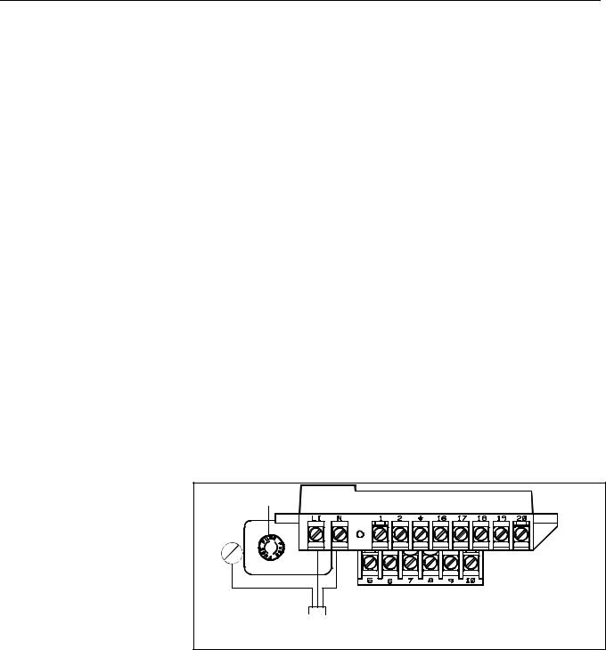
Figure 2-5. Transmitter Power
Connections
Connect 4–20 mA Loop
External Power Source
Fuse |
|
AC Line or |
|
AC Ground or |
AC Neutral or |
DC Ground |
|
Transmitter |
|
Power Cable |
|
The 4–20 mA output loop provides the process variable output from the transmitter. Its signal may be powered internally or externally. The default position of the internal/external analog power switch is in the internal position. The user-selectable power switch is located on the electronics board.
2-9
Rosemount 8712
Reference Manual
00809-0100-4664, Rev BA
January 2010
Internal
The 4–20 mA analog power loop may be powered from the transmitter itself. Resistance in the loop must be 1,000 ohms or less. If a Handheld Communicator or control system will be used, it must be connected across a minimum of 250 ohms resistance in the loop.
External
HART multidrop installations require a 10–30 V DC external power source (see Multidrop Communications on page 3-16). If a Handheld Communicator or control system is to be used, it must be connected across a minimum of 250 ohms resistance in the loop.
To connect external power to the 4–20 mA loop, complete the following steps.
1.Ensure that the power source and connecting cable meet the requirements outlined above and in Electrical Considerations on page 2-7.
2.Turn off the transmitter and analog power sources.
3.Run the power cable into the transmitter.
4.Connect –DC to Terminal 8.
5.Connect +DC to Terminal 7.
Figure 2-6. 4–20 mA Loop
Power Connections
Refer to Figure 2-6 on page 2-10. |
|
Fuse |
|
+4–20 mA power |
–4–20 mA power |
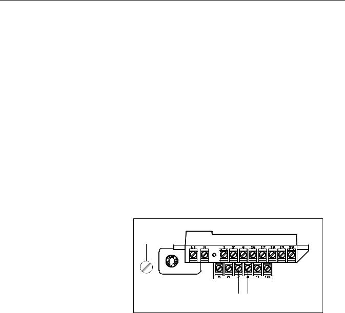
Connect Pulse Output
Power Source
The pulse output function provides an isolated switch-closure frequency signal that is proportional to the flow through the sensor. The signal is typically used in conjunction with an external totalizer or control system. The following requirements apply:
Supply Voltage: 5 to 24 V DC
Load Resistance: 1,000 to 100 k ohms (typical 5 k)
Pulse Duration: 1.5 to 500 msec (adjustable), 50% duty cycle below 1.5 msec Maximum Power: 2.0 watts up to 4,000 Hz and 0.1 watts at 10,000 Hz
Switch Closure: solid state switch
2-10
Reference Manual
00809-0100-4664, Rev BA
January 2010
Rosemount 8712
Figure 2-7. Connecting to a Electromechanical Totalizer/Counter
Figure 2-8. Connecting to a Electronic Totalizer/Counter without Integral Power Supply
Connect Auxiliary
Channel 1
The pulse output option requires an external power source. Complete the following steps to connect an external power supply.
1.Ensure that the power source and connecting cable meet the requirements outlined previously.
2.Turn off the transmitter and pulse output power sources.
3.Run the power cable to the transmitter.
4.Connect –DC to terminal 6.
5.Connect +DC to terminal 5.
Refer to Figure 2-7 and Figure 2-8. |
|
|
|
|
+ |
– |
|
Electro-mecha |
– |
– |
5–28 V DC |
nical Counter |
+ |
+ |
Power |
|
Supply |
||
|
+ |
– |
|
5–28 V DC |
– |
– |
|
Electronic |
|||
Power |
|
||
|
Counter |
||
Supply |
|
||
+ 1k to 100 k |
+ |
||
|
|||
|
Typical 5 k |
|
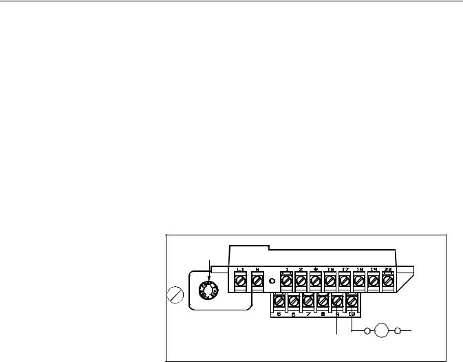
Auxiliary channel 1 can be configured as either a digital input or a digital output. When configured as an input, the following requirements apply:
Supply Voltage: |
5 to 28V DC |
Maximum Power: |
2 watts |
Switch Closure: |
optically isolated solid state switch |
Maximum Impedance |
2.5 k |
When using channel 1 as a digital input, the power source and the control relay must be connected to the transmitter. See Figure 2-9 for more details on this connection.
2-11
Rosemount 8712
Reference Manual
00809-0100-4664, Rev BA
January 2010
When configured as an output, the following requirements apply:
Supply Voltage: |
5 to 28V DC |
Maximum Power: |
2 watts |
Switch Closure: |
optically isolated solid state switch |
When using channel 1 as a digital output, the power source must be connected to the transmitter. See Figure 2-10 for more details on this connection.
When connecting power to channel 1, complete the following steps:
1.Ensure that the power source and connecting cable meet the requirements outlined previously.
2.Turn off the transmitter and auxiliary power sources.
3.Run the power cable to the transmitter.
4.Connect –DC to terminal 10.
5.Connect +DC to terminal 9.
Figure 2-9. Connect Digital Input 1 to Relay or Input to Control System
Fuse |
Control Relay |
or Input |
DC– |
DC+ |
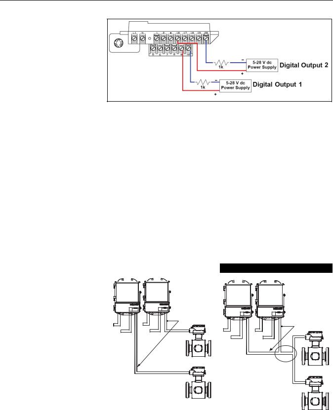
Connect Auxiliary
Channel 2
Auxiliary channel 2 is configured to provide a digital output based on the configuration parameters set in the transmitter.
The following requirements apply to this channel:
Supply Voltage: |
5 to 28V DC |
Maximum Power: |
2 watts |
Switch Closure: |
optically isolated solid state switch |
When connecting power to channel 2, complete the following steps:
1.Ensure that the power source and connecting cable meet the requirements outlined previously.
2.Turn off the transmitter and auxiliary power sources.
3.Run the power cable to the transmitter.
4.Connect –DC to terminal 20.
5.Connect +DC to terminal 16.
See Figure 2-10 for more details on this connection.
2-12
Reference Manual
00809-0100-4664, Rev BA
January 2010
Rosemount 8712
Figure 2-10. Connecting Digital
Outputs
SENSOR CONNECTIONS This section covers the steps required to physically install the transmitter including wiring and calibration.
Rosemount Sensors
Transmitter to
Sensor Wiring
To connect the transmitter to a non-Rosemount sensor, refer to the appropriate wiring diagram in Appendix D: Wiring Diagrams. The calibration procedure listed is not required for use with Rosemount sensors.
Flanged and wafer sensors have two conduit ports as shown in Figures 4-13, 4-14, 4-15, and 4-16. Either one may be used for both the coil drive and electrode cables. Use the stainless steel plug that is provided to seal the unused conduit port.
A single dedicated conduit run for the coil drive and electrode cables is needed between a sensor and a remote transmitter. Bundled cables in a single conduit are likely to create interference and noise problems in your system. Use one set of cables per conduit run. See Figure 2-11 for proper conduit installation diagram and Table 2-3 for recommended cable. For integral and remote wiring diagrams refer to Figure 2-13.
Figure 2-11. Conduit Preparation
|
|
|
|
|
|
|
Correct |
|
|
|
|
|
|
Incorrect |
|||||||
|
|
|
|
|
|
|
|
|
|
|
|
|
|
|
|
|
|
|
|
|
|
|
|
|
|
|
|
|
|
|
|
|
|
|
|
|
|
|
|
|
|
|
|
|
|
|
|
|
|
|
|
|
|
|
|
|
|
|
|
|
|
|
|
|
|
|
|
|
|
|
|
|
|
|
|
|
|
|
|
|
|
|
|
|
|
|
|
|
|
|
|
|
|
|
|
|
|
|
|
|
|
|
|
|
|
|
|
|
|
|
|
Coil Drive |
|
|
and |
|
|
Electrode |
Power |
Power |
Cables |
Outputs |
Outputs |
|
|
|
Coil Drive |
|
|
and |
|
|
Electrode |
Power |
Power |
Cables |
Outputs |
Outputs |
|
2-13

Rosemount 8712
Reference Manual
00809-0100-4664, Rev BA
January 2010
Table 2-3. Cable Requirements
|
Description |
Units |
Part Number |
||||
|
Signal Cable (20 AWG) Belden 8762, Alpha 2411 equivalent |
ft |
08712-0061-0001 |
||||
|
|
|
|
|
m |
08712-0061-0003 |
|
|
Coil Drive Cable (14 AWG) Belden 8720, Alpha 2442 equivalent |
ft |
08712-0060-0001 |
||||
|
|
|
|
|
m |
08712-0060-0003 |
|
|
Combination Signal and Coil Drive Cable (18 AWG)(1) |
ft |
08712-0752-0001 |
||||
|
|
|
|
|
m |
08712-0752-0003 |
|
|
(1) Combination signal and coil drive cable is not recommended for |
|
|
|
|||
|
high-signal magmeter system. For remote mount installations, combination signal and coil drive cable |
||||||
|
should be limited to less than 300 ft. (100 m). |
|
|
|
|||
|
Rosemount recommends using the combination signal and coil drive for N5, |
||||||
|
E5 approved sensors for optimum performance. |
|
|
|
|||
|
Remote transmitter installations require equal lengths of signal and coil drive |
||||||
|
cables. Integrally mounted transmitters are factory wired and do not require |
||||||
|
interconnecting cables. |
|
|
|
|||
|
Lengths from 5 to 1,000 feet (1.5 to 300 meters) may be specified, and will be |
||||||
|
shipped with the sensor. |
|
|
|
|||
Conduit Cables |
Run the appropriate size cable through the conduit connections in your |
||||||
|
magnetic flowmeter system. Run the power cable from the power source to |
||||||
|
the transmitter. Run the coil drive and electrode cables between the flowmeter |
||||||
|
and transmitter. |
|
|
|
|||
|
Prepare the ends of the coil drive and electrode cables as shown in Figure |
||||||
|
2-12. Limit the unshielded wire length to 1-inch on both the electrode and coil |
||||||
|
drive cables. |
|
|
|
|||
|
|
|
|
|
|
|
|
|
NOTE |
|
|
|
|||
|
Excessive lead length or failure to connect cable shields can create electrical |
||||||
|
noise resulting in unstable meter readings. |
|
|
|
|||
Figure 2-12. Cable Preparation |
|
|
|
|
|
|
|
|
|
|
|
|
|
|
|
|
|
|
|
|
|
|
|
Detail |
|
|
|
|
|
|
|
1.00 |
|
|
|
|
|||
|
|
|
(26) |
|
|
|
|
|
NOTE |
|
Dimensions are in |
Cable Shield |
inches (millimeters). |
2-14
Reference Manual
00809-0100-4664, Rev BA
January 2010
Rosemount 8712
Sensor to Remote Mount Transmitter Connections
Connect coil drive and electrode cables as shown in Figure 2-13.
Do not connect AC power to the sensor or to terminals 1 and 2 of the transmitter, or replacement of the electronics board will be necessary.
Figure 2-13. Wiring Diagram
Rosemount 8712 Transmitter |
Rosemount 8705/8707/8711/8721 sensors |
||||||
|
|
|
|
|
|
|
|
1 |
|
1 |
|
||||
|
|
|
|
|
|
|
|
2 |
|
2 |
|
||||
|
|
|
|
|
|
|
|
|
|
|
|
|
|
|
|
|
|
|
|
|
|
|
|
17 |
17 |
||||||
18 |
18 |
||||||
|
|
|
|
|
|
|
|
19 |
19 |
||||||
|
|
|
|
|
|
|
|
2-15

Rosemount 8712
Reference Manual
00809-0100-4664, Rev BA
January 2010
2-16

Reference Manual
00809-0100-4664, Rev BA
January 2010
Rosemount 8712
Section 3 |
Configuration |
INTRODUCTION
INSTALLATION CHECK AND GUIDE
Introduction . . . . . . . . . . . . . . . . . . . . . . . . . . . . . . . . . . . . . page 3-1 Installation Check and Guide . . . . . . . . . . . . . . . . . . . . . . page 3-1 Basic Features . . . . . . . . . . . . . . . . . . . . . . . . . . . . . . . . . . page 3-3 LOI Examples . . . . . . . . . . . . . . . . . . . . . . . . . . . . . . . . . . . page 3-4 Diagnostic Messages . . . . . . . . . . . . . . . . . . . . . . . . . . . . . page 3-6 Process Variables . . . . . . . . . . . . . . . . . . . . . . . . . . . . . . . . page 3-6 Basic Setup . . . . . . . . . . . . . . . . . . . . . . . . . . . . . . . . . . . . . page 3-8
This section covers basic operation, software functionality, and configuration procedures for the Rosemount 8712 Magnetic Flowmeter Transmitter. For information on connecting another manufacturer’s sensor, refer to “Universal Sensor Wiring Diagrams” on page E-1.
The Rosemount 8712 features a full range of software functions for configuration of output from the transmitter. Software functions are accessed through the LOI, AMS, a Handheld Communicator, or a control system. Configuration variables may be changed at any time and specific instructions are provided through on-screen instructions.
Table 3-1. Parameters
Basic Set-up Parameters |
Page |
Review |
page 3-6 |
Process Variables |
page 3-6 |
Basic Setup |
page 3-8 |
Flow Units |
page 3-8 |
Range Values |
page 3-11 |
PV Sensor Calibration Number |
page 3-12 |
Totalizer Setup |
page 3-7 |
Use this guide to check new installations of Rosemount magnetic flowmeter systems that appear to malfunction.
Before You Begin
www.rosemount.com

Rosemount 8712
Reference Manual
00809-0100-4664, Rev BA
January 2010
Transmitter
Apply power to your system before making the following transmitter checks.
1.Verify that the correct sensor calibration number is entered in the transmitter. The calibration number is listed on the sensor nameplate.
2.Verify that the correct sensor line size is entered in the transmitter. The line size value is listed on the sensor nameplate.
3.Verify that the analog range of the transmitter matches the analog range in the control system.
4.Verify that the forced analog output of the transmitter produces the correct output at the control system.
Sensor
Be sure that power to your system is removed before beginning sensor checks.
1.For horizontal flow installations, ensure that the electrodes remain covered by process fluid.
For vertical or inclined installations, ensure that the process fluid is flowing up into the sensor to keep the electrodes covered by process fluid.
2.Ensure that the grounding straps on the sensor are connected to grounding rings, lining protectors, or the adjacent pipe flanges. Improper grounding will cause erratic operation of the system.
Wiring
LOCAL OPERATOR INTERFACE
1.The signal wire and coil drive wire must be twisted shielded cable. Emerson Process Management, Rosemount division. recommends 20 AWG twisted shielded cable for the electrodes and 14 AWG twisted shielded cable for the coils.
2.The cable shield must be connected at both ends of the electrode and coil drive cables. Connection of the shield at both ends is absolutely necessary for proper operation.
3.The signal and coil drive wires must be separate cables, unless Emerson Process Management specified combo cable is used.
4.The single conduit that houses both the signal and coil drive cables should not contain any other wires.
Process Fluid
1.The process fluid conductivity should be 5 microsiemens (5 micro mhos) per centimeter minimum.
2.The process fluid must be free of air and gasses.
3.The sensor should be full of process fluid.
Refer to Section 6 "Maintenance and Troubleshooting" for further information.
The optional Local Operator Interface (LOI) provides an operator communications center for the 8712. By using the LOI, the operator can access any transmitter function for changing configuration parameter settings, checking totalized values, or other functions. The LOI is integral to the transmitter housing.
3-2
Reference Manual
00809-0100-4664, Rev BA
January 2010
Rosemount 8712
BASIC FEATURES
The basic features of the LOI include display control, totalizer, data entry, and transmitter parameters. These features provide control of all transmitter functions, see Figure 3-1.
Display Control Keys
The display control keys provide control over the variable displayed on the LOI screen. Push FLOW RATE to display the process variable, or push TOTALIZE to display the totalized value.
Totalizer Keys
The totalizer keys enable you to start, stop, read, and reset the totalizer.
Data Entry Keys
The data entry keys enable you to move the display cursor, incrementally increase the value, or enter the selected value.
Transmitter Parameter Keys
The transmitter parameter keys provide direct access to the most common transmitter parameters and stepped access to the advanced functions of the 8712 through the AUX. FUNCTION key.
Figure 3-1. Local Operator
Interface Keypad
Data Entry
DISPLAY CONTROL |
TOTALIZER |
DATA |
|||
ENTRY |
|||||
|
|
|
|
||
FLOW |
|
|
READ |
SHIFT |
|
TOTALIZE |
|
|
|
||
RATE |
|
|
|
||
|
|
|
|
||
|
|
|
RESET |
|
|
|
TUBE |
|
AUX. |
INCR. |
|
TUBE CAL |
UNITS |
|
|||
SIZE |
FUNCTION |
|
|||
NO. |
|
|
|
|
|
ANALOG |
PULSE |
|
|
|
|
OUTPUT |
OUTPUT |
DAMPING |
XMTR |
ENTER |
|
RANGE |
SCALING |
|
INFO |
||
|
|
||||
|
TRANSMITTER PARAMETERS |
|
|
||
The LOI keypad does not have numerical keys. Numerical data is entered by the following procedure.
1.Access the appropriate function.
2.Use SHIFT to highlight the digit you want to enter or change.
3.Use INCR. to change the highlighted value. For numerical data, INCR. toggle through the digits 0–9, decimal point, and dash. For alphabetical data, toggle through the letters of the alphabet A–Z, digits 0–9, and the symbols l,&, +, -, *, /, $, @,%, and the blank space. (INCR. is also used to toggle through pre-determined choices that do not require data entry.)
4.Use SHIFT to highlight other digits you want to change and change them.
5.Press ENTER.
3-3

Rosemount 8712
Reference Manual
00809-0100-4664, Rev BA
January 2010
Selecting Options
LOI EXAMPLES
Table Value Example
To select pre-defined software options on the LOI, use the following procedure:
1.Access the appropriate option.
2.Use SHIFT or INCR. to toggle between the applicable choices.
3.Press ENTER when the desired choice is displayed on the screen.
Use the TRANSMITTER PARAMETER keys shown in Figure 3-1 to change the parameters, which are set in one of two ways, table values or select values.
Table Values:
Parameters such as units, that are available from a predefined list
Select Values:
Parameters that consist of a user-created number or character string, such as calibration number; values are entered one character at a time using the data entry keys
Setting the sensor line size:
1.Press TUBE SIZE.
2.Press SHIFT or INCR. to increase (incrementally) the size to the next value.
3.When you reach the desired size, press ENTER.
4.Set the loop to manual if necessary, and press ENTER again.
After a moment, the LCD will display the new tube size and the maximum flow rate.
Select Value Example Changing the ANALOG OUTPUT RANGE:
1.Press ANALOG OUTPUT RANGE.
2.Press SHIFT to position the cursor.
3.Press INCR. to set the number.
4.Repeat steps 2 and 3 until desired number is displayed.
5.Press ENTER.
After a moment, the LCD will display the new analog output range. Table 3-2. LOI Data Entry Keys and Functions
Data Entry Keys |
|
Function Performed |
|
|
|
Shift |
• |
Moves the blinking cursor on the display one character to the right |
|
• |
Scrolls through available values |
Increment |
• |
Increments the character over the cursor by one |
|
• |
Steps through all the digits, letters, and symbols that are applicable to the present operation |
|
• |
Scrolls through available values |
|
|
|
Enter |
Stores the displayed value previously selected with the SHIFT and INCR. keys |
|
Display Control Keys |
Function Performed |
|
Flow Rate |
Displays the user-selected parameters for flow indication |
|
Totalize |
Displays the present totalized output of the transmitter, and activates the Totalizer group of keys |
|
|
The choices, Forward and Reverse totals or Net and Gross totals, are selected in Auxiliary Functions |
|
Start/Stop |
Starts the totalizing display if it is stopped, and stops the display if it is running |
|
Read/Reset |
Resets the net totalizing display to zero if it is stopped, and halts the display if the display is running |
|
3-4
 Loading...