

Page 1
Product Data Sheet
00813-0100-4485, Rev HC
September 2019
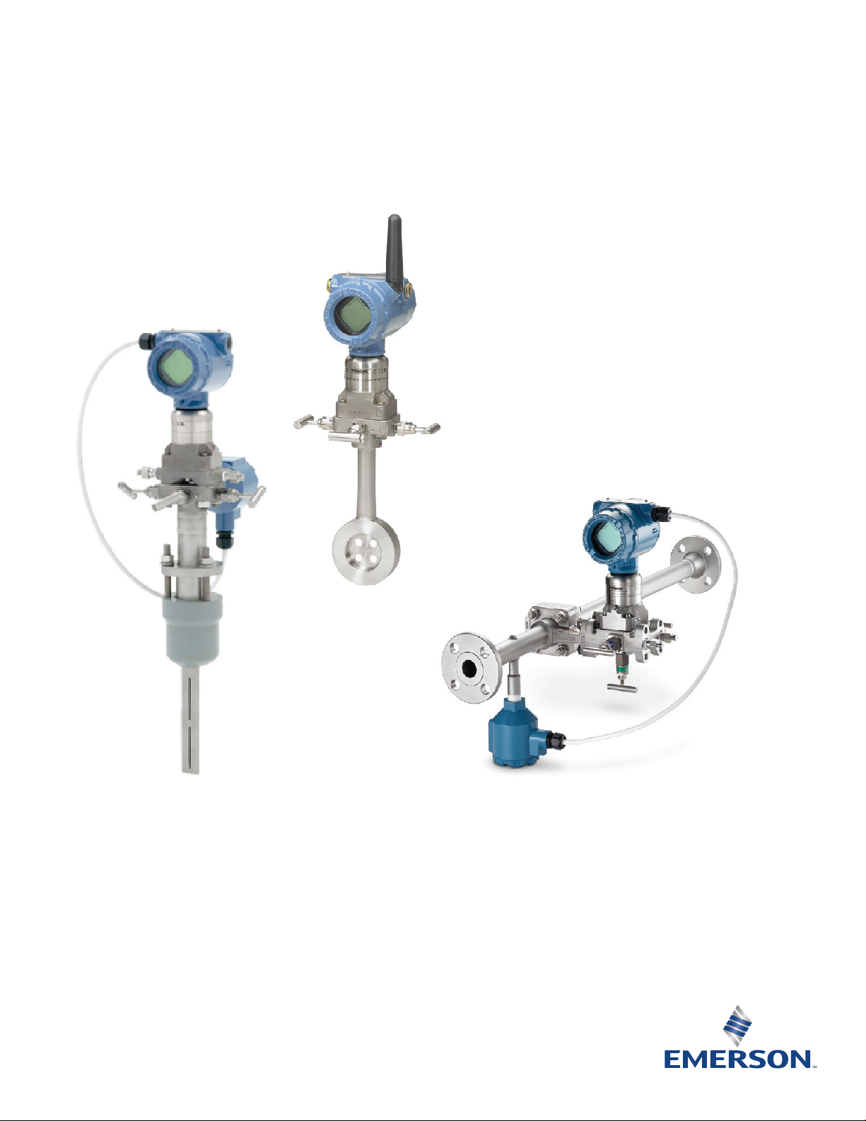
Rosemount™ DP Flow Meters and Primary
Elements
■
Multivariable capabilities allow for real-time fully compensated mass and energy flow
■
Fully-integrated wireless flow meters allow for easy installation
■
Minimize permanent pressure loss and save energy with Rosemount Annubar™ Averaging Pitot Tube
Technology
■
Reduce straight pipe requirements to two diameters upstream and downstream from most flow
disturbances with Conditioning Orifice Technology
■
Improve accuracy and repeatability in small line sizes with Integral Orifice Plate Technology
Page 2

September 2019
Contents
DP Flow Meter Selection Guide..........................................................................................................................................................2
Rosemount 3051SF DP Flow Meter....................................................................................................................................................5
Specifications.................................................................................................................................................................................. 35
Product certifications...................................................................................................................................................................... 50
Rosemount™ 3051CF Flow Meter Series...........................................................................................................................................77
Specifications.................................................................................................................................................................................. 99
Product certifications.................................................................................................................................................................... 112
Rosemount 2051CF Flow Meter Series...........................................................................................................................................127
Specifications................................................................................................................................................................................ 147
Product certifications.................................................................................................................................................................... 158
Rosemount 485 Annubar Primary Element.................................................................................................................................... 171
Specifications................................................................................................................................................................................ 177
Pipe I.D. range code for Rosemount Annubar Flow Meters and Primary Elements..........................................................................182
Rosemount 585 Annubar Primary Element.................................................................................................................................... 186
Specifications................................................................................................................................................................................ 192
Rosemount 405 Compact Primary Element................................................................................................................................... 197
Specifications................................................................................................................................................................................ 200
Rosemount 1595 Conditioning Orifice Plate..................................................................................................................................207
Specifications................................................................................................................................................................................ 210
Rosemount 1195 Integral Orifice Primary Element........................................................................................................................ 213
Specifications................................................................................................................................................................................ 217
Rosemount 1495 Orifice Plate....................................................................................................................................................... 221
Rosemount 1496 Orifice Flange Union.......................................................................................................................................... 225
Specifications................................................................................................................................................................................ 229
Installation and flow meter orientation..........................................................................................................................................233
Dimensional drawings................................................................................................................................................................... 245
2 Emerson.com/Rosemount
Page 3
September 2019
DP Flow Meter Selection Guide
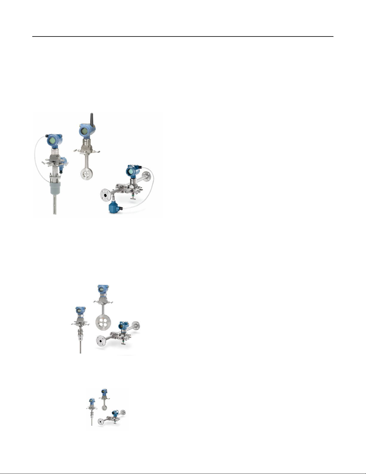
Rosemount integrated DP Flow Meters arrive fully assembled, configured, and leak tested for out-of-the-box installation.
Rosemount 3051SF Flow Meters enable best-in-class flow measurement utilizing advanced functionality
■
Up to 0.80 percent mass flow rate accuracy
■
Multivariable capabilities allow for real-time, fully
compensated mass, and energy flow
■
Advanced diagnostics predict and prevent abnormal
process conditions
■
Installation ready wireless flow solution
■
Ultra for Flow measures percent-of-reading performance
over 14:1 flow turndown
■
Ultra for Flow measures percent-of-reading performance
over 14:1 flow turndown
■
15-year stability, 15-year warranty
■
SIL3 Capable: IEC 61508 certified by an accredited third
party agency for use in safety instrumented systems up to
SIL 3 (minimum requirement of single use [1oo1] for SIL 2
and redundant use [1oo2] for SIL 3)
■
Available with 4–20 mA HART®, WirelessHART, and
FOUNDATION™ Fieldbus Protocols
Rosemount 3051CF Flow Meters combine the proven 3051C Pressure Transmitter and the latest primary
element technology
■
Up to 1.65 percent volumetric flow accuracy at 8:1
turndown
■
Available with HART, WirelessHART, FOUNDATION Fieldbus,
and PROFIBUS® Protocols
■
10-year stability
■
SIL3 Capable: IEC 61508 certified by an accredited 3rd party
agency for use in safety instrumented systems up to SIL 3
(minimum requirement of single use [1oo1] for SIL 2 and
redundant use [1oo2] for SIL 3)
Rosemount 2051CF Flow Meters combine the 2051C Pressure Transmitter and the latest primary element
technology
■
Up to 2.00 percent volumetric flow accuracy at 5:1
turndown
■
Available with HART, WirelessHART, and FOUNDATION
Fieldbus Protocols
■
3-year stability
Emerson.com/Rosemount 3
Page 4
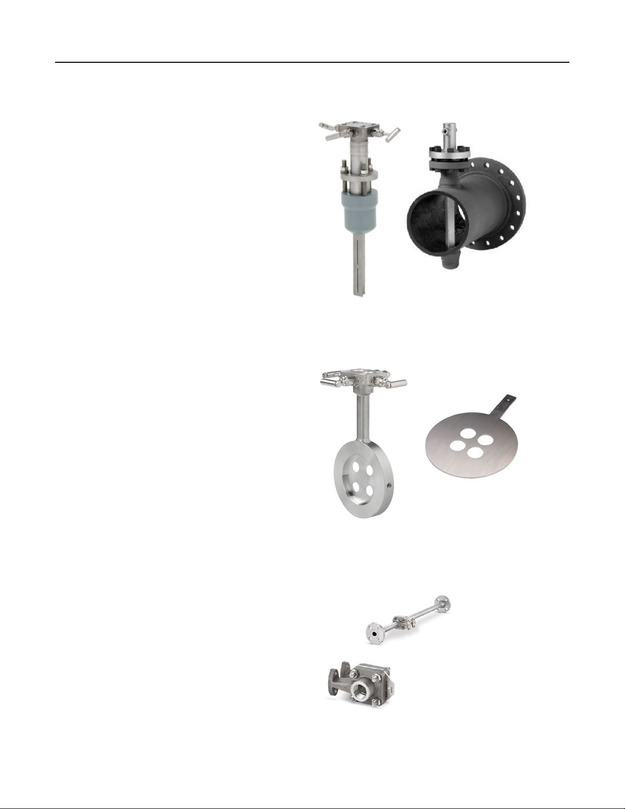
Rosemount Annubar Primary Element Technology
■
Energy savings gained through minimal permanent
pressure loss
■
Innovative T-shape design providing accuracies up to ±0.75
percent of flow rate (Rosemount 485 Annubar Primary
Element)
■
Variety of sensor materials for optimal compatibility with
the process fluid
■
Handles applications where conditions exceed the structural
limitations of other primary elements
■
Symmetrical sensor design allows bi-directional flow
measurement (Rosemount 585 Annubar Primary Element)
■
Rosemount 405A Compact Annubar primary element easily
installs like an orifice plate
■
Integral thermowell allows temperature measurement
without additional pipe penetrations for Rosemount 485,
585, and 405A models.
Rosemount Conditioning Orifice Plate Technology
September 2019
■
Reduce straight pipe requirements to two diameters
upstream and downstream from most flow disturbances
■
Discharge coefficient uncertainty as low as ±0.5 percent
■
Integral thermowell allows temperature measurement
without an additional pipe penetration with the compact
design
■
Reduce installation costs compared to traditional orifice
plates with the compact design
■
Conditioning orifice plate is based on AGA, ASME, and ISO
industry standards
■
Available in various plate styles providing installation
flexibility
Rosemount Integral Orifice Plate Technology
■
Improves accuracy and repeatability in ½-in., 1-in., and 1½in. line sizes
■
Self-centering plate design eliminates installation errors
that are magnified in small line sizes
■
Precision honed pipe sections allow accuracy of up to ±0.75
percent of flow rate
■
Installation flexibility with numerous process connections
■
Integral thermowell allows temperature measurement
without an additional pipe penetration
4 Emerson.com/Rosemount
Page 5
September 2019
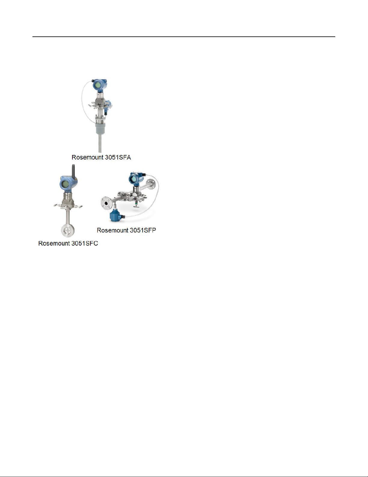
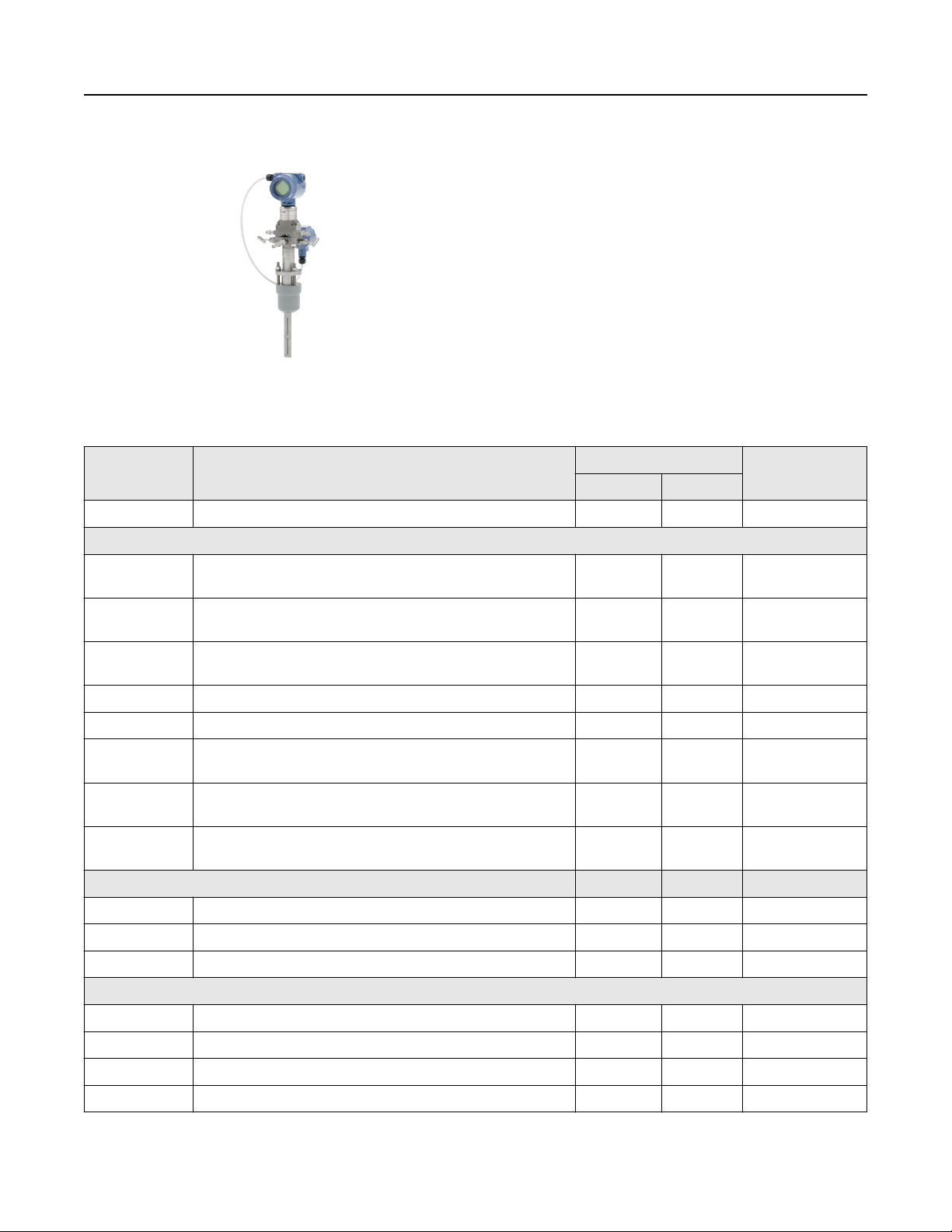
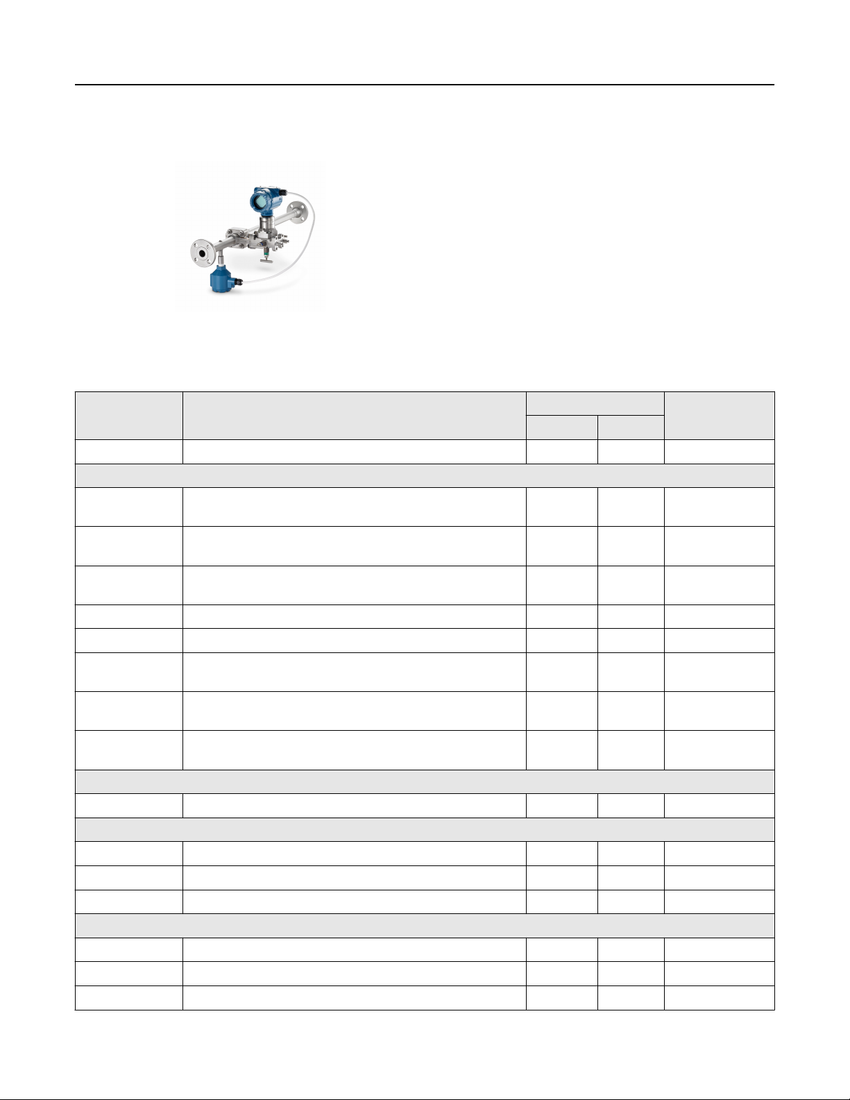
Rosemount 3051SF DP Flow Meter
Rosemount 3051SF Flow Meters integrate industry leading
transmitters with industry leading primary elements.
Capabilities include:
■
Flow meters are factory configured to meet your application
needs (Configuration Data Sheet required)
■
Multivariable capabilities allow scalable flow compensation
(measurement types 1–4)
■
4–20 mA HART, WirelessHART, and FOUNDATION Fieldbus
Protocols
■
Ultra for Flow for improved flow performance across wider
flow ranges
■
Integral temperature measurement (option code T)
■
Advanced diagnostics (option code DA2)
■
Direct or remote mount configurations available
Additional information
Specifications
Dimensional drawings: Rosemount 3051SF DP Flow Meters
Emerson.com/Rosemount 5
Page 6
September 2019
Rosemount 3051SFA Annubar Flow Meter ordering information
■
Rosemount Annubar Flow Meters reduce permanent
pressure loss by creating less blockage in the pipe.
■
Ideal for large line size installations when cost, size and
weight of the flow meter are concerns.
Specification and selection of product materials, options, or
components must be made by the purchaser of the equipment.
See Process-wetted parts for more information on material
selection.
Table 1: Rosemount 3051SFA Annubar Flow Meter Ordering Information
The starred offerings (★) represent the most common options and should be selected for best delivery. The non-starred offerings
are subject to additional delivery lead time.
Model Product description Measurement type • = Available
D 1-7
3051SFA Rosemount Annubar Flow Meter • •
— =Unavailable
Measurement type
1 Fully compensated mass and energy flow calculations –
differential and static pressures with temperature
2 Compensated flow calculations – differential and static
pressures
3 Compensated flow calculations – differential pressure and
temperature
4 Compensated flow calculations – differential pressure — • ★
D Differential pressure • — ★
5 Process variables only (no flow calculations) – differential and
static pressures with temperature
6 Process variables only (no flow calculations) – differential and
static pressures
7 Process variables only (no flow calculations) – differential
pressure and temperature
Fluid type
L Liquid • • ★
G Gas • • ★
S Steam • • ★
Line Size
— • ★
— • ★
— • ★
— • ★
— • ★
— • ★
020 2-in. (50 mm) • • ★
025 2½-in. (63,5 mm) • • ★
030 3-in. (80 mm) • • ★
035 3½-in. (89 mm) • • ★
6 Emerson.com/Rosemount
Page 7

September 2019
Table 1: Rosemount 3051SFA Annubar Flow Meter Ordering Information (continued)
Model Product description Measurement type • = Available
D 1-7
— =Unavailable
040 4-in. (100 mm) • • ★
050 5-in. (125 mm) • • ★
060 6-in. (150 mm) • • ★
070 7-in. (175 mm) • • ★
080 8-in. (200 mm) • • ★
100 10-in. (250 mm) • • ★
120 12-in. (300 mm) • • ★
140 14-in. (350 mm) • •
160 16-in. (400 mm) • •
180 18-in. (450 mm) • •
200 20-in. (500 mm) • •
240 24-in. (600 mm) • •
300 30-in. (750 mm) • •
360 36-in. (900 mm) • •
420 42-in. (1066 mm) • •
480 48-in. (1210 mm) • •
600 60-in. (1520 mm) • •
720 72-in. (1820 mm) • •
780 78-in. (1950 mm) • •
840 84-in. (2100 mm) • •
900 90-in. (2250 mm) • •
960 96-in. (2400 mm) • •
Pipe I.D. range (see “Pipe I.D. range code for Rosemount Annubar Flow Meters and Primary Elements”)
C Range C from the pipe I.D. table • • ★
D Range D from the pipe I.D. table • • ★
A Range A from the pipe I.D. table • •
B Range B from the pipe I.D. table • •
E Range E from the pipe I.D. table • •
Z Non-standard pipe I.D. range or line sizes greater than 12-in.
• •
(300 mm)
Pipe material/mounting assembly material
C CS (A105) • • ★
S 316 Stainless steel (SST) • • ★
(1)
0
No mounting (customer supplied) • • ★
Emerson.com/Rosemount 7
Page 8

September 2019
Table 1: Rosemount 3051SFA Annubar Flow Meter Ordering Information (continued)
Model Product description Measurement type • = Available
D 1-7
— =Unavailable
G Chrome-moly grade F-11 • •
N Chrome-moly grade F-22 • •
J Chrome-moly grade F-91 • •
Piping orientation
H Horizontal piping • • ★
D Vertical piping with downwards flow • • ★
U Vertical piping with upwards flow • • ★
Rosemount Annubar type
P Pak-lok • • ★
F Flanged with opposite side support • • ★
L Flange-lok • •
G Gear-drive flo-tap • •
M Manual flo-tap • •
Sensor material
S 316 SST • • ★
H Alloy C-276 • •
Sensor size
1 Sensor size 1 — line sizes 2- to 8-in. (50 to 200 mm) • • ★
2 Sensor size 2 — line sizes 6- to 96-in. (150 to 2400 mm) • • ★
3 Sensor size 3 — line sizes greater than 12-in. (300 mm) • • ★
Mounting type
T1 Compression/threaded connection • • ★
A1 ANSI Class 150 RF • • ★
A3 ANSI Class 300 RF • • ★
A6 ANSI Class 600 RF • • ★
D1 DN PN 16 flange • • ★
D3 DN PN 40 flange • • ★
D6 DN PN 100 flange • • ★
(2)
A9
AF
AT
(2)
(2)
ANSI Class 900 RF • •
ANSI Class 1500 RF • •
ANSI Class 2500 RF • •
R1 ANSI flange Class 150 RTJ • •
R3 ANSI flange Class 300 RTJ • •
R6 ANSI flange Class 600 RTJ • •
8 Emerson.com/Rosemount
Page 9
September 2019
Table 1: Rosemount 3051SFA Annubar Flow Meter Ordering Information (continued)
Model Product description Measurement type • = Available
— =Unavailable
R9
RF
RT
(2)
(2)
(2)
D 1-7
ANSI flange Class 900 RTJ • •
ANSI flange Class 1500 RTJ • •
ANSI flange Class 2500 RTJ • •
Opposite side support or packing gland
0 • • ★
Opposite side support (required for flanged models)
C • • ★
D • • ★
Packing gland (required for flo-tap models)
Packing gland material Rod
material
(3)
J
SST packing gland/cage nipple Carbon
Packing
material
PTFE • •
steel (CS)
(3)
K
(3)
L
(3)
N
R Alloy C-276 packing gland/cage
SST packing gland/cage nipple SST PTFE • •
SST packing gland/cage nipple CS Graphite • •
SST packing gland/cage nipple SST Graphite • •
SST Graphite • •
nipple
Isolation valve for flo-tap models
0 Not applicable or customer supplied • • ★
1 Gate valve, CS • •
2 Gate valve, SST • •
5 Ball valve, CS • •
6 Ball valve, SST • •
Temperature measurement
T Integral RTD – not available with flanged model greater than
• • ★
Class 600
0 No temperature sensor • • ★
R Remote thermowell and RTD • •
Transmitter connection platform
3 Direct-mount, Integral 3-valve manifold– not available with
• • ★
flanged model greater than Class 600
5 Direct-mount, 5-valve manifold – not available with flanged
• • ★
model greater than Class 600
7 Remote-mount NPT connections (½ NPT) • • ★
6 Direct-mount, high temperature 5-valve manifold – not
• •
available with flanged model greater than Class 600
Emerson.com/Rosemount 9
Page 10

September 2019
Table 1: Rosemount 3051SFA Annubar Flow Meter Ordering Information (continued)
Model Product description Measurement type • = Available
D 1-7
— =Unavailable
8 Remote-mount SW connections (½-in.) • •
Differential pressure range
1 0 to 25 inH2O (0 to 62,16 mbar) • • ★
2 0 to 250 inH2O (0 to 621,60 mbar) • • ★
3 0 to 1000 inH2O (0 to 2,48 bar) • • ★
Static pressure range
(4)
A
None • • ★
D Absolute 0 to 800 psia (0 to 55,15 bar) — • ★
(5)
E
Absolute 0 to 3626 psia (0 to 250,00 bar) — • ★
J Gage –14.2 to 800 psig (–0.98 to 55,15 bar) — • ★
(5)
K
Gage –14.2 to 3626 psig (–0.98 to 250,00 bar) — • ★
Transmitter output
A 4–20 mA with digital signal based on HART Protocol • • ★
(6)
F
X
(7)(8)
FOUNDATION Fieldbus Protocol (requires Plantweb™ housing) • • ★
Wireless (requires wireless options and wireless Plantweb
• • ★
housing)
Transmitter housing style Material Conduit
entry size
00 None (customer-supplied electrical
N/A N/A • — ★
connection)
1A Plantweb housing Aluminum ½–14 NPT • • ★
1B Plantweb housing Aluminum M20 x 1.5 • • ★
1J Plantweb housing SST ½–14 NPT • • ★
1K Plantweb housing SST M20 x 1.5 • • ★
2A Junction box housing Aluminum ½–14 NPT • — ★
2B Junction box housing Aluminum M20 x 1.5 • — ★
2E Junction box housing with output for
Aluminum ½–14 NPT • — ★
remote display and interface
2F Junction box housing with output for
Aluminum M20 x 1.5 • — ★
remote display and interface
2J Junction box housing SST ½–14 NPT • — ★
2M Junction box housing with output for
SST ½–14 NPT • — ★
remote display and interface
(9)
5A
5J
7J
(9)
(7)(10)
Wireless Plantweb housing Aluminum ½–14 NPT • • ★
Wireless Plantweb housing SST ½–14 NPT • • ★
Quick connect (A size mini, 4-pin
N/A N/A • — ★
male termination)
10 Emerson.com/Rosemount
Page 11
September 2019
Table 1: Rosemount 3051SFA Annubar Flow Meter Ordering Information (continued)
Model Product description Measurement type • = Available
D 1-7
— =Unavailable
1C Plantweb housing Aluminum G½ • •
1L Plantweb housing SST G½ • •
2C Junction box housing Aluminum G½ • —
2G Junction box housing with output for
Aluminum G½ • —
remote display and interface
Performance class
(11)
Rosemount 3051S MultiVariable™ SuperModule™, measurement types 1, 2,
5, and 6
(12)
3
Ultra for flow: 0.8% flow rate accuracy, 14:1 flow turndown,
15-year stability, 15-year limited warranty
5 Classic MV: 1.15% flow rate accuracy, 8:1 flow turndown, 15-
yr. stability
Rosemount 3051S Single Variable SuperModule, Measurement Types 3, 4,
7, and D
1 Ultra: up to 0.95% flow rate accuracy, 8:1 flow turndown, 15-
year stability, 15-year limited warranty
2 Classic: up to 1.4% flow rate accuracy, 8:1 flow turndown, 15-
year stability
(12)
3
Ultra for flow: 0.8% flow rate accuracy, 14:1 flow turndown,
15-year stability, 15-year limited warranty
Wireless options
(8)
(requires option code X and wireless Plantweb housing)
Update rate, operating frequency and protocol
WA3 User configurable update rate, 2.4 GHz DSSS, IEC 62591
(WirelessHART Protocol)
Omni-directional wireless antenna and SmartPower
™
• • ★
— • ★
• • ★
• • ★
• • ★
• • ★
WK1 External antenna, adapter for Black Power module (I.S. Power
• • ★
Module sold separately)
WM1 Extended range, external antenna, adapter for Black Power
• • ★
Module (I.S. Power Module sold separately)
WN1 High-gain, remote antenna, adapter for Black Power Module
• •
(I.S. Power Module sold separately)
Other options (include with selected model number)
HART Revision configuration (requires HART output code A)
(13)
HR7 Configured for HART Revision 7 • — ★
Extended product warranty
WR3 3-year limited warranty • • ★
WR5 5-year limited warranty • • ★
Pressure testing
(14)
P1 Hydrostatic testing with certificate • •
Emerson.com/Rosemount 11
Page 12

September 2019
Table 1: Rosemount 3051SFA Annubar Flow Meter Ordering Information (continued)
Model Product description Measurement type • = Available
D 1-7
— =Unavailable
PX Extended hydrostatic testing • •
Special cleaning
P2 Cleaning for special services • •
PA Cleaning per ASTM G93 level D (section 11.4) • •
Material testing
V1 Dye penetrant exam • •
Material examination
V2 Radiographic examination • •
Flow calibration
W1 Flow calibration (Average K) • •
WZ Special calibration • •
Special inspection
QC1 Visual and dimensional inspection with certificate • • ★
QC7 Inspection and performance certificate • • ★
Surface finish
RL Surface finish for low pipe Reynolds number in gas and steam • • ★
RH Surface finish for high pipe Reynolds number in liquid • • ★
Material traceability certification
(15)
Q8 Material traceability certificate per EN 10204:2004 3.1 • • ★
Positive material identification
Q76 PMI verification and certification • •
Code conformance
(16)
J2 ANSI/ASME B31.1 • •
J3 ANSI/ASME B31.3 • •
(17)
J5
NACE® MR-0175/ISO 15156 • •
J6 European Pressure Directive (PED) • • ★
J1 Canadian Registration • •
Installed in flanged pipe spool section
H3 Class 150 flanged connection with Rosemount standard
• •
length and schedule
H4 Class 300 flanged connection with Rosemount standard
• •
length and schedule
H5 Class 600 flanged connection with Rosemount standard
• •
length and schedule
12 Emerson.com/Rosemount
Page 13

September 2019
Table 1: Rosemount 3051SFA Annubar Flow Meter Ordering Information (continued)
Model Product description Measurement type • = Available
D 1-7
— =Unavailable
Instrument connections for remote mount option
G2 Needle valves, SST • • ★
G6 OS&Y gate valve, SST • • ★
G1 Needle valves, CS • •
G3 Needle valves, alloy C-276 • •
G5 OS&Y gate valve, CS • •
G7 OS&Y gate valve, alloy C-276 • •
Special shipment
Y1 Mounting hardware shipped separately • • ★
Special dimensions
VM Variable mounting • •
VT Variable tip • •
VS Variable length spool section • •
Transmitter calibration certification
Q4 Calibration certificate for transmitter • • ★
QP Calibration certificate and tamper evident seal • • ★
Quality certification for safety
(18)(26)
QS Prior-use certificate of FMEDA data • — ★
(20)
QT
Safety certified to IEC 61508 with certificate of FMEDA data • — ★
Product certifications
E1 ATEX Flameproof • • ★
I1 ATEX Intrinsic Safety • • ★
IA ATEX FISCO Intrinsic Safety; for FOUNDATION Fieldbus only • • ★
N1 ATEX Type n • • ★
ND ATEX Dust • • ★
K1 ATEX Flameproof, Intrinsic Safety, Type n, and Dust
• • ★
(combination of E1, I1, N1, and ND)
E4 TIIS Flameproof • • ★
E5 FM Explosion-proof, Dust Ignition-proof • • ★
I5 FM Intrinsically Safe; Nonincendive • • ★
IE FM FISCO Intrinsically Safe for FOUNDATION Fieldbus only. • • ★
K5 FM Explosion-proof, Dust Ignition-proof, Intrinsically Safe,
• • ★
Division 2 (combination of E5 and I5)
(19)
E6
CSA Explosion-proof, Dust Ignition-proof, Division 2 • • ★
I6 CSA Intrinsically Safe • • ★
Emerson.com/Rosemount 13
Page 14

September 2019
Table 1: Rosemount 3051SFA Annubar Flow Meter Ordering Information (continued)
Model Product description Measurement type • = Available
D 1-7
— =Unavailable
IF CSA FISCO Intrinsic Safety • • ★
(19)
K6
CSA Explosion-proof, Dust Ignition-proof, Intrinsically Safe,
• • ★
and Division 2 (combination of E6 and I6)
E7 IECEx Flameproof, Dust Ignition-proof • • ★
I7 IECEx Intrinsic Safety • • ★
IG IECEx FISCO Intrinsic Safety • • ★
N7 IECEx Type n • • ★
K7 IECEx Flameproof, Dust Ignition-proof, Intrinsic Safety, Type n
• • ★
(combination of E7, I7, and N7)
E3 China Flameproof • • ★
I3 China Intrinsic Safety • • ★
EM Technical Regulations Customs Union (EAC) Flameproof • • ★
IM Technical Regulations Customs Union (EAC) Intrinsic Safety • • ★
KM Technical Regulations Customs Union (EAC) Flameproof,
• • ★
Intrinsic Safety
EP Republic of Korea Flameproof • • ★
IP Republic of Korea Intrinsic Safety • • ★
KP Republic of Korea Flameproof, Intrinsic Safety • • ★
KA ATEX and CSA Flameproof, Intrinsically Safe, Division 2
• • ★
(combination of E1, I1, E6, and I6)
KB FM and CSA Explosion-proof, Dust Ignition-proof, Intrinsically
• • ★
Safe, Div 2 (combination of E5, E6, I5, and I6)
KC FM and ATEX Explosion-proof, Intrinsically Safe, Division 2
• • ★
(combination of E5, E1, I5, and I1)
(19)
KD
FM, CSA, and ATEX Explosion-proof, Intrinsically Safe
• • ★
(combination of E5, I5, E6, I6, E1, and I1)
E2 INMETRO Flameproof • • ★
Shipboard approvals
SBS American Bureau of Shipping • • ★
SBV Bureau Veritas (BV) Type Approval • • ★
SDN Det Norske Veritas (DNV) Type Approval • • ★
SLL Lloyds Register (LR) Type Approval • • ★
Sensor fill fluid and O-ring options
L1 Inert sensor fill fluid • • ★
L2 Graphite-filled (PTFE) O-ring • • ★
LA Inert sensor fill fluid and graphite-filled (PTFE) O-ring • • ★
14 Emerson.com/Rosemount
Page 15

September 2019
Table 1: Rosemount 3051SFA Annubar Flow Meter Ordering Information (continued)
Model Product description Measurement type • = Available
— =Unavailable
Digital display
D 1-7
(20)
M5 Plantweb LCD display (requires Plantweb housing) • • ★
(21)(22)(23)
M7
Remote mount LCD display and interface, Plantweb housing,
• — ★
no cable; SST bracket
(21)(22)
M8
Remote mount LCD display and interface, Plantweb housing,
• — ★
50 ft. (15 m) cable; SST bracket
(21)(22)
M9
Remote mount LCD display and interface, Plantweb housing,
• — ★
100 ft. (31 m) cable; SST bracket
Transient protection
(24)
T1 Transient terminal block • • ★
Manifold for remote mount option
F2 3-valve manifold, SST • • ★
F6 5-valve manifold, SST • • ★
F1 3-valve manifold, CS • •
F3 3-valve manifold, alloy C-276 • •
F5 5-valve manifold, CS • •
F7 5-valve manifold, alloy C-276 • •
Plantweb control functionality
A01 FOUNDATION Fieldbus Advanced Control Function Block Suite • — ★
Plantweb diagnostic functionality
D01 FOUNDATION Fieldbus Diagnostics Suite • — ★
(25)(26)
DA2
Plantweb enhanced measurement functionality
Advanced HART Diagnostic Suite • — ★
(27)
H01 FOUNDATION Fieldbus fully compensated mass flow block • — ★
Cold temperature
(28)
BRR –60 °F (–51 °C) Cold temperature start-up • • ★
Alarm limit
(21)(26)
C4 NAMUR alarm and saturation levels, high alarm • • ★
C5 NAMUR alarm and saturation levels, high alarm • • ★
C6 Custom alarm and saturation levels, high alarm • • ★
C7 Custom alarm and saturation levels, high alarm • • ★
C8 Low alarm (standard Rosemount alarm and saturation levels) • • ★
Hardware adjustments and ground screw
(21)(26)(29)
D1
D4
(30)
Hardware adjustments (zero, span, alarm, security) • — ★
External ground screw assembly • • ★
Emerson.com/Rosemount 15
Page 16

September 2019
Table 1: Rosemount 3051SFA Annubar Flow Meter Ordering Information (continued)
Model Product description Measurement type • = Available
— =Unavailable
(21)(26)(29)
DA
Hardware adjustments (zero, span, alarm, security) and
D 1-7
• — ★
external ground screw assembly
Conduit plug
DO 316 SST conduit plug • • ★
Conduit electrical connector
(31)
GE M12, 4-pin, male connector (eurofast®) • • ★
GM A size mini, 4-pin, male connector (minifast®) • • ★
Typical model number: 3051SFA D L 060 D C H P S 2 T1 0 0 0 3 2A A 1A 3
Provide the “A” dimension for flanged, flange-lok, and threaded flo-tap models. Provide the “B” dimension for flange flo-tap models.
(1)
Available in remote mount applications only.
(2)
The cage nipple is constructed of 304SST.
(3)
Required for measurement type codes 3, 4, 7, and D.
(4)
For measurement type codes 1, 2, 5, and 6 with DP range 1, absolute limits are 0.5 to 2000 psi (0,03 to 137,9 bar) and gage limits are –14.2 to
(5)
2000 psig (–0,98 to 137,9 bar).
Transmitter output code F is only available with measurement type code 1, 2, 5, 6, and D.
(6)
Only intrinsically safe approval codes apply.
(7)
Only available with measurement types D and 6.
(8)
Only available with output code X.
(9)
Only available with output code A.
(10)
For detailed specifications see “Specifications”.
(11)
Only available with differential pressure ranges 2 and 3, and silicone fill fluid.
(12)
Option HR7 configures the HART output to HART Revision 7. This option requires the selection of the advanced diagnostic (DA2) option. The
(13)
device with this option can be field configured to HART Revision 5 or 7 if desired.
Applies to assembled flow meter only, mounting not tested.
(14)
Instrument connections for remote mount options and isolation valves for flo-tap models are not included in the Material Traceability
(15)
Certification.
Not available with transmitter connection platform 6.
(16)
Materials of construction comply with metallurgical requirements within NACE® MR0175/ISO 15156 for sour oil field production environments.
(17)
Environmental limits apply to certain materials. Consult latest standard for details. Selected materials also conform to NACE MR0103 for sour
refining environments.
Not available with output code F.
(18)
Not available with M20 or G1/2 conduit entry size.
(19)
Not available with housing code 7J.
(20)
Not available with output code X. Only available with measurement type D.
(21)
Not available with output code F, option code DA2, or option code QT.
(22)
See the Rosemount 3051S Reference Manual for cable requirements. Contact an Emerson representative for additional information.
(23)
Not available with housing code 5A, 5J, or 7J. External ground screw assembly (option code D4) is included with the T1 option. The T1 option is
(24)
not needed with FISCO Product Certifications.
Includes hardware adjustments (option code D1) as standard. Not available with output code X. Only available with measurement type D.
(25)
Not available with output code F.
(26)
Requires Rosemount Engineering Assistant to configure (to ensure correct operation download the Engineering Assistant software at:
(27)
Emerson.com/Rosemount/Engineering Assistant Software).
–58 °F (50 °C) for measurement type 1-7.
(28)
Not available with housing codes 2E, 2F, 2G, 2M, 5A, 5J, or 7J.
(29)
This assembly is included with options E1, N1, K1, ND, E4, E7, N7, K7, E2, E3, KA, KC, KD, IA, IE, N3, T1, EM, and KM.
(30)
Not available with housing code 5A, 5J, or 7J. Available with Intrinsically Safe approvals only. For FM Intrinsically Safe; Nonincendive (option code
(31)
I5) or FM FISCO Intrinsically Safe (option code IE), install in accordance with Rosemount drawing 03151-1009.
16 Emerson.com/Rosemount
Page 17

September 2019
Rosemount 3051SFC Compact Orifice Flow Meter ordering information
■
Compact conditioning flow meters reduce straight piping requirements to 2D
upstream and 2D downstream from most flow disturbances.
■
Ideal for large line size installations when cost, size and weight of the flow
meter are concerns.
Specification and selection of product materials, options, or components must be
made by the purchaser of the equipment. See page 43 for more information on
material selection.
Specification and selection of product materials, options, or components must be
made by the purchaser of theequipment. See Process-wetted parts for more
information on material selection.
Table 2: Rosemount 3051SFC Compact Orifice Flow Meter Ordering Information
The starred offerings (★) represent the most common options and should be selected for best delivery. The non-starred offerings
are subject to additional delivery lead time.
Model Product description Measurement type • = Available
D 1-7
— =Unavailable
3051SFC Compact orifice flow meter • •
Measurement type
1 Fully compensated mass and energy flow calculations – Differential and
— • ★
static pressures with temperature
2 Compensated flow calculations – differential and static pressures — • ★
3 Compensated flow calculations – differential pressure and temperature — • ★
4 Compensated flow calculations – differential pressure — • ★
D Differential pressure • — ★
5 Process variables only (no flow calculations) – differential and static
— •
pressures with temperature
6 Process variables only (no flow calculations) – differential and static
— •
pressures
7 Process variables only (no flow calculations) – differential pressure and
— •
temperature
Primary element technology
A Rosemount Annubar averaging pitot tube • • ★
C Conditioning orifice plate • • ★
P Orifice plate • • ★
Material type
S 316 SST • • ★
Line Size
(1)
005
010
015
(1)
(1)
½-in. (15 mm) • • ★
1-in. (25 mm) • • ★
1½-in. (40 mm) • • ★
Emerson.com/Rosemount 17
Page 18

September 2019
Table 2: Rosemount 3051SFC Compact Orifice Flow Meter Ordering Information (continued)
Model Product description Measurement type • = Available
D 1-7
— =Unavailable
020 2-in. (50 mm) • • ★
025 2½-in. (63,5 mm) • • ★
030 3-in. (80 mm) • • ★
035 3½-in. (89 mm) • • ★
040 4-in. (100 mm) • • ★
050 5-in. (125 mm) • • ★
060 6-in. (150 mm) • • ★
070 7-in. (175 mm) • • ★
080 8-in. (200 mm) • • ★
(2)(3)
100
120
(2)(3)
10-in. (250 mm) • • ★
12-in. (300 mm) • • ★
Primary element type
N000 Rosemount Annubar sensor size 1 • • ★
N040 0.40 beta ratio (β) • • ★
N050 0.50 beta ratio (β) • • ★
(4)
N065
0.65 beta ratio (β) • • ★
Temperature measurement
(5)
T
Integral RTD – not available with flanged model greater than Class 600 — • ★
0 No temperature sensor • • ★
(5)
R
Remote thermowell and RTD • •
Transmitter connection platform
3 Direct-mount, Integral 3-valve manifold– not available with flanged
• • ★
model greater than Class 600
7 Remote-mount NPT connections (½ NPT) • • ★
Differential pressure range
1 0 to 25 inH2O (0 to 62,16 mbar) • • ★
2 0 to 250 inH2O (0 to 621,60 mbar) • • ★
3 0 to 1000 inH2O (0 to 2,48 bar) • • ★
Static pressure range
(6)
A
None • • ★
D Absolute 0 to 800 psia (0 to 55,15 bar) — • ★
(7)
E
Absolute 0 to 3626 psia (0 to 250,00 bar) — • ★
J Gage –14.2 to 800 psig (–0.98 to 55,15 bar) — • ★
(7)
K
Gage –14.2 to 3626 psig (–0.98 to 250,00 bar) — • ★
18 Emerson.com/Rosemount
Page 19
September 2019
Table 2: Rosemount 3051SFC Compact Orifice Flow Meter Ordering Information (continued)
Model Product description Measurement type • = Available
D 1-7
— =Unavailable
Transmitter output
A 4–20 mA with digital signal based on HART Protocol • • ★
(8)(9)
F
(10)(11)
X
FOUNDATION Fieldbus Protocol • • ★
Wireless • • ★
Transmitter housing style Material Conduit entry
size
00 None (customer-supplied electrical
N/A N/A • — ★
connection)
1A Plantweb housing Aluminum ½–14 NPT • • ★
1B Plantweb housing Aluminum M20 x 1.5 • • ★
1J Plantweb housing SST ½–14 NPT • • ★
1K Plantweb housing SST M20 x 1.5 • • ★
2A Junction box housing Aluminum ½–14 NPT • — ★
2B Junction box housing Aluminum M20 x 1.5 • — ★
2E Junction box housing with output for
Aluminum ½–14 NPT • — ★
remote display and interface
2F Junction box housing with output for
Aluminum M20 x 1.5 • — ★
remote display and interface
2J Junction box housing SST ½–14 NPT • — ★
2M Junction box housing with output for
SST ½–14 NPT • — ★
remote display and interface
(12)
5A
(12)
5J
(10)(13)
7J
Wireless Plantweb housing Aluminum ½–14 NPT • • ★
Wireless Plantweb housing SST ½–14 NPT • • ★
Quick connect (A size mini, 4-pin male
N/A N/A • — ★
termination)
1C Plantweb housing Aluminum G½ • •
1L Plantweb housing SST G½ • •
2C Junction box housing Aluminum G½ • —
2G Junction box housing with output for
Aluminum G½ • —
remote display and interface
Performance class
(14)
Rosemount 3051S MultiVariable SuperModule, measurement types 1, 2, 5, and 6
(15)
3
Ultra for flow: 0.75% flow rate accuracy, 14:1 flow turndown, 15-yr
• • ★
stability, 15-yr limited warranty
5 Classic MV: 1.10% flow rate accuracy, 8:1 flow turndown, 15-yr stability — • ★
Rosemount 3051S Single Variable SuperModule, Measurement Types 3, 4, 7, and
D
Emerson.com/Rosemount 19
Page 20

September 2019
Table 2: Rosemount 3051SFC Compact Orifice Flow Meter Ordering Information (continued)
Model Product description Measurement type • = Available
D 1-7
— =Unavailable
1 Ultra: 0.90% flow rate accuracy, 8:1 flow turndown, 15-yr stability, 15-yr
• • ★
limited warranty
2 Classic: 1.40% flow rate accuracy, 8:1 flow turndown, 15-yr stability • • ★
(15)
3
Ultra for Flow: 0.75% flow rate accuracy, 14:1 flow turndown, 15-yr
• • ★
stability, 15-yr limited warranty
Wireless options
(11)
(requires option code X and wireless Plantweb housing)
Update rate, operating frequency and protocol
WA3 User configurable update rate, 2.4 GHz DSSS, IEC 62591 (WirelessHART
• • ★
Protocol)
Omni-directional wireless antenna and SmartPower
WK1 External antenna, adapter for Black Power module (I.S. Power Module
• • ★
sold separately)
WM1 Extended range, external antenna, adapter for Black Power Module (I.S.
• • ★
Power Module sold separately)
WN1 High-gain, remote antenna, adapter for Black Power Module (I.S. Power
• •
Module sold separately)
Other options (include with selected model number)
HART Revision configuration (requires HART output code A)
(16)
HR7 Configured for HART Revision 7 • — ★
Extended product warranty
WR3 3-year limited warranty • • ★
WR5 5-year limited warranty • • ★
Installation accessories
A ANSI alignment ring (Class 150)
• • ★
(only required for 10- and 12-in. [250 and 300 mm] line sizes)
C ANSI alignment ring (Class 300)
• • ★
(only required for 10- and 12-in. [250 and 300 mm] line sizes)
D ANSI alignment ring (Class 600)
• • ★
(only required for 10- and 12-in. [250 and 300 mm] line sizes)
G DIN alignment ring (PN 16) • • ★
H DIN alignment ring (PN 40) • • ★
J DIN alignment ring (PN 100) • • ★
B JIS alignment ring (10K) • •
R JIS alignment ring (20K) • •
S JIS alignment ring (40K) • •
Remote adapters
E Flange adapters 316 SST (½ NPT) • • ★
20 Emerson.com/Rosemount
Page 21

September 2019
Table 2: Rosemount 3051SFC Compact Orifice Flow Meter Ordering Information (continued)
Model Product description Measurement type • = Available
D 1-7
— =Unavailable
High temperature applications
T Graphite valve packing (T
= 850 °F • •
max
Flow calibration
(17)
WC
WD
(18)(19)
Flow calibration, 3 Pt, conditioning option C (all pipe schedules) • •
Flow calibration, 10 pt, conditioning option C (all schedules),
• •
Rosemount Annubar option A (schedule 40)
Pressure testing
P1 Hydrostatic testing with certificate • •
Special cleaning
(20)
P2 Cleaning for special services • •
PA Cleaning per ASTM G93 level D (section 11.4) • •
Special inspection
QC1 Visual and dimensional inspection with certificate • • ★
QC7 Inspection and performance certificate • • ★
Transmitter calibration certification
Q4 Calibration certificate for transmitter • • ★
QP Calibration certificate and tamper evident seal • • ★
Quality certification for safety
(21)(22)
QS Prior-use certificate of FMEDA data • — ★
QT Safety certified to IEC 61508 with certificate of FMEDA data • — ★
Material traceability certifications
Q8 Material traceability certification per EN 10204:2004 3.1 • • ★
Positive material identification
Q76 PMI Verification and Certification • •
Code conformance
J2 ANSI/ASME B31.1 • •
J3 ANSI/ASME B31.3 • •
J5 NACE MR-0175/ISO 15156
(23)
• •
Country certification
J1 Canadian registration • •
Product certifications
E1 ATEX Flameproof • • ★
I1 ATEX Intrinsic Safety • • ★
IA ATEX FISCO Intrinsic Safety; for FOUNDATION Fieldbus only • • ★
Emerson.com/Rosemount 21
Page 22

September 2019
Table 2: Rosemount 3051SFC Compact Orifice Flow Meter Ordering Information (continued)
Model Product description Measurement type • = Available
D 1-7
— =Unavailable
N1 ATEX Type n • • ★
ND ATEX Dust • • ★
K1 ATEX Flameproof, Intrinsic Safety, Type n, Dust (combination of E1, I1,
• • ★
N1, and ND)
E4 TIIS Flameproof • • ★
E5 FM Explosion-proof, Dust Ignition-proof • • ★
I5 FM Intrinsically Safe; Nonincendive • • ★
IE FM FISCO Intrinsically Safe for FOUNDATION Fieldbus only. • • ★
K5 FM Explosion-proof, Dust Ignition-proof, Intrinsically Safe, Division 2
• • ★
(combination of E5 and I5)
(24)
E6
CSA Explosion-proof, Dust Ignition-proof, Division 2 • • ★
I6 CSA Intrinsically Safe • • ★
IF CSA FISCO Intrinsic Safety • • ★
(24)
K6
CSA Explosion-proof, Dust Ignition-proof, Intrinsically Safe, Division 2
• • ★
(combination of E6 and I6)
E7 IECEx Flameproof, Dust Ignition-proof • • ★
I7 IECEx Intrinsic Safety • • ★
IG IECEx FISCO Intrinsic Safety • • ★
K7 IECEx Flameproof, Dust Ignition-proof, Intrinsic Safety, Type n
• • ★
(combination of E7, I7, and N7)
E3 China Flameproof • • ★
I3 China Intrinsic Safety • • ★
IP Republic of Korea Intrinsic Safety • • ★
KP Republic of Korea Flameproof, Intrinsic Safety • • ★
EP Republic of Korea Flameproof • • ★
EM Technical Regulations Customs Union (EAC) Flameproof • • ★
IM Technical Regulations Customs Union (EAC) Intrinsic Safety • • ★
KM Technical Regulations Customs Union (EAC) Flameproof, Intrinsic
• • ★
Safety
(24)
KA
ATEX and CSA Flameproof, Intrinsically Safe, Division 2 (combination of
• • ★
E1, I1, E6, and I6)
(24)
KB
FM and CSA Explosion-proof, Dust Ignition-proof, Intrinsically Safe, Div
• • ★
2 (combination of E5, E6, I5, and I6)
KC FM and ATEX Explosion-proof, Intrinsically Safe, Division 2
• • ★
(combination of E5, E1, I5, and I1)
(24)
KD
FM, CSA, and ATEX Explosion-proof, Intrinsically Safe (combination of
• • ★
E5, I5, E6, I6, E1, and I1)
22 Emerson.com/Rosemount
Page 23

September 2019
Table 2: Rosemount 3051SFC Compact Orifice Flow Meter Ordering Information (continued)
Model Product description Measurement type • = Available
D 1-7
— =Unavailable
E2 INMETRO Flameproof • • ★
I2 INMETRO Intrinsic Safety • • ★
K2 INMETRO Flameproof, Intrinsic Safety • • ★
IB INMETRO FISCO Intrinsic Safety • — ★
Shipboard approvals
SBS American Bureau of Shipping • • ★
SBV Bureau Veritas (BV) Type Approval • • ★
SDN Det Norske Veritas (DNV) Type Approval • • ★
SLL Lloyds Register (LR) Type Approval • • ★
Sensor fill fluid and O-ring options
L1 Inert sensor fill fluid • • ★
L2 Graphite-filled (PTFE) O-ring • • ★
LA Inert sensor fill fluid and graphite-filled (PTFE) O-ring • • ★
Digital display
(25)
M5 Plantweb LCD display (requires Plantweb housing) • • ★
(26)(27)(28
M7
)
M8
(26)(27)
Remote mount LCD display and interface, Plantweb housing, no cable;
SST bracket
Remote mount LCD display and interface, Plantweb housing, 50 ft. (15
• — ★
• — ★
m) cable; SST bracket
(26)(27)
M9
Remote mount LCD display and interface, Plantweb housing, 100 ft.
• — ★
(31 m) cable; SST bracket
Transient protection
(29)
T1 Transient terminal block • • ★
Manifold for remote mount option
F2 3-valve manifold, SST • • ★
F6 5-valve manifold, SST • • ★
Plantweb control functionality
A01 FOUNDATION Fieldbus Advanced Control Function Block Suite • — ★
Plantweb diagnostic functionality
D01 FOUNDATION Fieldbus Diagnostics Suite • — ★
(30)
DA2
Advanced HART Diagnostic Suite • — ★
H01 FOUNDATION Fieldbus fully compensated mass flow block • — ★
Cold temperature
(31)
BRR
BR6
(32)
–60 °F (–51 °C) Cold temperature start-up • • ★
–76 °F (–60 °C) cold temperature • • ★
Emerson.com/Rosemount 23
Page 24

September 2019
Table 2: Rosemount 3051SFC Compact Orifice Flow Meter Ordering Information (continued)
Model Product description Measurement type • = Available
— =Unavailable
Alarm limit
D 1-7
(21)(26)
C4 NAMUR alarm and saturation levels, high alarm • • ★
C5 NAMUR alarm and saturation levels, low alarm • • ★
C6 Custom alarm and saturation levels, high alarm • • ★
C7 Custom alarm and saturation levels, low alarm • • ★
C8 Low alarm (standard Rosemount alarm and saturation levels) • • ★
Hardware adjustments and ground screw
(21)(26)(33)
D1
(34)
D4
(21)(26)(33)
DA
Hardware adjustments (zero, span, alarm, security) • — ★
External ground screw assembly • • ★
Hardware adjustments (zero, span, alarm, security) and external
• — ★
ground screw assembly
Conduit plug
DO 316 SST conduit plug • • ★
Conduit electrical connector
(35)
ZE M12, 4-pin, male connector (eurofast) • • ★
ZM A size mini, 4-pin, male connector (minifast) • • ★
Typical model number: 3051SFC 1 C S 060 N 065 T 3 2 J A 1A 3
Available with Primary Element Technology P only.
(1)
For the 10- and 12-in. (250 and 300 mm) line sizes, the alignment ring must be ordered (installation accessories).
(2)
10- and 12-in. (250 and 300 mm) line sizes not available with Primary Element Technology code A.
(3)
For 2-in. (50 mm) line size the beta ratio is 0.6 for Primary Element Technology code C.
(4)
Only available with measurement type codes 1, 3, 5, and 7.
(5)
Required for measurement type codes 3, 4, 7, and D.
(6)
For measurement type codes 1, 2, 5, and 6 with DP range 1, absolute limits are 0.5 to 2000 psi (0,03 to 137,9 bar) and gage limits are –14.2 to
(7)
2000 psig (–0,98 to 137,9 bar).
Requires Plantweb housing.
(8)
Transmitter output code F is only available with measurement type code 1, 2, 5, 6, and D.
(9)
Only intrinsically safe approval codes apply.
(10)
Only available with measurement types D and 6.
(11)
Only available with output code X.
(12)
Available with output code A only.
(13)
For detailed specifications see Specifications.
(14)
Only available with differential pressure ranges 2 and 3, and silicone fill fluid.
(15)
Option HR7 configures the HART output to HART Revision 7. This option requires the selection of the advanced diagnostics (DA2) option. The
(16)
device with this option can be field configured to HART Revision 5 or 7 if desired.
Available with Primary Element Technology code C only.
(17)
Available with Primary Element Technology codes C or A only.
(18)
For Rosemount Annubar option A, consult factory for pipe schedules other than Sch. 40.
(19)
Available with Primary Element Technology C or P only.
(20)
Not available with output code F.
(21)
Not available with output code X.
(22)
Materials of construction comply with metallurgical requirements within NACE MR0175/ISO for sour oil field production environments.
(23)
Environmental limits apply to certain materials. Consult latest standard for details. Selected materials also conform to NACE MR0103 for sour
refining environments.
Not available with M20 or G½ conduit entry size.
(24)
24 Emerson.com/Rosemount
Page 25

September 2019
Not available with housing code 7J.
(25)
Not available with output code X. Only available with measurement type D.
(26)
Not available with output code F, option code DA2, or option code QT.
(27)
See the Rosemount 3051S Reference Manual for cable requirements. Contact an Emerson representative for additional information.
(28)
Not available with housing code 00, 5A, 5J, or 7J. External ground screw assembly (option code D4) is included with the T1 option. The T1 option
(29)
is not needed with FISCO Product Certifications.
Includes hardware adjustments (option code D1) as standard. Not available with output code X. Only available with measurement type D.
(30)
Only available with MultiVariable measurement types 1-7.
(31)
Only available with measurement type D.
(32)
Not available with housing codes 2E, 2F, 2G, 2M, 5A, 5J, or 7J.
(33)
This assembly is included with options EP, KP, E1, N1, K1, ND, E4, E7, K7, E3, KA, KC, KD, IA, T1, EM, and KM.
(34)
Not available with housing code 5A, 5J, or 7J. Available with Intrinsically Safe approvals only. For FM Intrinsically Safe; Nonincendive (option code
(35)
I5) or FM FISCO Intrinsically Safe (option code IE), install in accordance with Rosemount drawing 03151-1009.
Emerson.com/Rosemount 25
Page 26
September 2019
Rosemount™ 3051SFP Integral Orifice Flow Meter ordering information
■
Precision honed pipe section for increased accuracy in small
line sizes
■
Self-centering plate design prevents alignment errors that
magnify measurement inaccuracies in small line sizes
Specification and selection of product materials, options, or
components must be made by the purchaser of
thebequipment. See Physical specifications for more
information on material selection.
Table 3: Rosemount 3051SFP Integral Orifice Flow Meter Ordering Information
The starred offerings (★) represent the most common options and should be selected for best delivery. The non-starred offerings
are subject to additional delivery lead time.
Model Product description Measurement type • = Available
D 1-7
3051SFP Integral orifice flow meter • •
Measurement type
— =Unavailable
1 Fully compensated mass and energy flow calculations –
Differential and static pressures with temperature
2 Compensated flow calculations – Differential and static
pressures
3 Compensated flow calculations – Differential pressure and
temperature
4 Compensated flow calculations – Differential pressure — • ★
D Differential pressure • — ★
5 Process variables only (no flow calculations) – Differential and
static pressures with temperature
6 Process variables only (no flow calculations) – Differential and
static pressures
7 Process variables only (no flow calculations) – Differential
pressure and temperature
Body material and type
F 316 SST, enhanced support body • • ★
Line size
005 ½-in. (15 mm) • • ★
010 1-in. (25 mm) • • ★
015 1½-in. (40 mm) • • ★
— • ★
— • ★
— • ★
— •
— •
— •
Process connection
T1 NPT female body (not available with thermowell and RTD) • • ★
(1)
S1
P1 Pipe ends: NPT threaded • • ★
Socket weld body (not available with thermowell and RTD) • • ★
26 Emerson.com/Rosemount
Page 27

September 2019
Table 3: Rosemount 3051SFP Integral Orifice Flow Meter Ordering Information (continued)
Model Product description Measurement type • = Available
D 1-7
P2 Pipe ends: beveled • • ★
D1 Pipe ends: flanged, DIN PN 16, slip-on • • ★
D2 Pipe ends: flanged, DIN PN 40, slip-on • • ★
D3 Pipe ends: flanged, DIN PN 100, slip-on • • ★
W1 Pipe ends: flanged, RF, ANSI Class 150, weld-neck • • ★
W3 Pipe ends: flanged, RF, ANSI Class 300, weld-neck • • ★
W6 Pipe ends: flanged, RF, ANSI Class 600, weld-neck • • ★
W9 Pipe ends: flanged, RF, ANSI Class 900, weld-neck • • ★
A1 Pipe ends: flanged, RF, ANSI Class 150, slip-on • •
A3 Pipe ends: flanged, RF, ANSI Class 300, slip-on • •
A6 Pipe ends: flanged, RF, ANSI Class 600, slip-on • •
R1 Pipe ends: flanged, RTJ, ANSI Class 150, slip-on • •
— =Unavailable
R3 Pipe ends: flanged, RTJ, ANSI Class 300, slip-on • •
R6 Pipe ends: flanged, RTJ, ANSI Class 600, slip-on • •
R9 Pipe ends: flanged, RTJ, ANSI Class 900, weld-neck • •
P9 Special process connection • •
Orifice plate material
S 316/316L SST • • ★
H Alloy C-276 • •
M Alloy 400 • •
Bore size option
0066 0.066-in. (1.68 mm) for ½-in. pipe • • ★
0109 0.109-in. (2.77 mm) for ½-in. pipe • • ★
0160 0.160-in. (4.06 mm) for ½-in. pipe • • ★
0196 0.196-in. (4.98 mm) for ½-in. pipe • • ★
0260 0.260-in. (6.60 mm) for ½-in. pipe • • ★
0340 0.340-in. (8.64 mm) for ½-in. pipe • • ★
0150 0.150-in. (3.81 mm) for 1-in. pipe • • ★
0250 0.250-in. (6.35 mm) for 1-in. pipe • • ★
0345 0.345-in. (8.76 mm) for 1-in. pipe • • ★
0500 0.500-in. (12.70 mm) for 1-in. pipe • • ★
0630 0.630-in. (16.00 mm) for 1-in. pipe • • ★
0800 0.800-in. (20.32 mm) for 1-in. pipe • • ★
0295 0.295-in. (7.49 mm) for 1½-in. pipe • • ★
Emerson.com/Rosemount 27
Page 28

September 2019
Table 3: Rosemount 3051SFP Integral Orifice Flow Meter Ordering Information (continued)
Model Product description Measurement type • = Available
D 1-7
— =Unavailable
0376 0.376-in. (9.55 mm) for 1½-in. pipe • • ★
0512 0.512-in. (13.00 mm) for 1½-in. pipe • • ★
0748 0.748-in. (19.00 mm) for 1½-in. pipe • • ★
1022 1.022-in. (25.96 mm) for 1½-in. pipe • • ★
1184 1.184-in. (30.07 mm) for 1½-in. pipe • • ★
0010 0.010-in. (0.25 mm) for ½-in. pipe • •
0014 0.014-in. (0.36 mm) for ½-in. pipe • •
0020 0.020-in. (0.51 mm) for ½-in. pipe • •
0034 0.034-in. (0.86 mm) for ½-in. pipe • •
XXXX Special bore size • •
Transmitter connection platform
D3 Direct-mount, 3-valve manifold, SST • • ★
D5 Direct-mount, 5-valve manifold, SST • • ★
R3 Remote-mount, 3-valve manifold, SST • • ★
R5 Remote-mount, 5-valve manifold, SST • • ★
D4 Direct-mount, 3-valve manifold, alloy C-276 • •
D6 Direct-mount, 5-valve manifold, alloy C-276 • •
R4 Remote-mount, 3-valve manifold, alloy C-276 • •
R6 Remote-mount, 5-valve manifold, alloy C-276 • •
Differential pressure range
1 0 to 25 inH2O (0 to 62,16 mbar) • • ★
2 0 to 250 inH2O (0 to 621,60 mbar) • • ★
3 0 to 1000 inH2O (0 to 2,48 bar) • • ★
Static pressure range
(2)
A
None • • ★
D Absolute 0 to 800 psia (0 to 55,15 bar) — • ★
(3)
E
Absolute 0 to 3626 psia (0 to 250,00 bar) — • ★
J Gage –14.2 to 800 psig (–0.98 to 55,15 bar) — • ★
(3)
K
Gage –14.2 to 3626 psig (–0.98 to 250,00 bar) — • ★
Transmitter output
A 4–20 mA with digital signal based on HART Protocol • • ★
(4)
F
X
(5)(6)
FOUNDATION Fieldbus Protocol (requires Plantweb housing) • • ★
Wireless (requires wireless options and wireless Plantweb
• • ★
housing)
28 Emerson.com/Rosemount
Page 29

September 2019
Table 3: Rosemount 3051SFP Integral Orifice Flow Meter Ordering Information (continued)
Model Product description Measurement type • = Available
D 1-7
— =Unavailable
Transmitter housing style Material Conduit
entry size
00 None (customer-supplied electrical
N/A N/A • — ★
connection)
1A Plantweb housing Aluminum ½–14 NPT • • ★
1B Plantweb housing Aluminum M20 x 1.5 • • ★
1J Plantweb housing SST ½–14 NPT • • ★
1K Plantweb housing SST M20 x 1.5 • • ★
2A Junction box housing Aluminum ½–14 NPT • — ★
2B Junction box housing Aluminum M20 x 1.5 • — ★
2E Junction box housing with output
Aluminum ½–14 NPT • — ★
for remote display and interface
2F Junction box housing with output
Aluminum M20 x 1.5 • — ★
for remote display and interface
2J Junction box housing SST ½–14 NPT • — ★
2M Junction box housing with output
SST ½–14 NPT • — ★
for remote display and interface
(7)
5A
5J
7J
(7)
(5)(8)
Wireless Plantweb housing Aluminum ½–14 NPT • • ★
Wireless Plantweb housing SST ½–14 NPT • • ★
Quick connect (A size mini, 4-pin
N/A N/A • — ★
male termination)
1C Plantweb housing Aluminum G½ • •
1L Plantweb housing SST G½ • •
2C Junction box housing Aluminum G½ • —
2G Junction box housing with output
Aluminum G½ • —
for remote display and interface
Performance class
(9)
Rosemount 3051S MultiVariable SuperModule, measurement types 1, 2, 5,
and 6
(10)
3
Ultra for flow: 0.95% flow rate accuracy, 14:1 flow turndown,
• • ★
15-year stability, 15-year limited warranty
5 Classic MV: 1.25% flow rate accuracy, 8:1 flow turndown, 15-
— • ★
year stability
Rosemount 3051S Single Variable SuperModule, Measurement Types 3, 4, 7,
and D
1 Ultra: 1.05% flow rate accuracy, 8:1 flow turndown, 15-year
• • ★
stability, 15-year limited warranty
2 Classic: 1.50% flow rate accuracy, 8:1 flow turndown, 15-year
• • ★
stability
Emerson.com/Rosemount 29
Page 30
September 2019
Table 3: Rosemount 3051SFP Integral Orifice Flow Meter Ordering Information (continued)
Model Product description Measurement type • = Available
D 1-7
(10)
3
Ultra for Flow: 0.95% flow rate accuracy, 14:1 flow turndown,
• • ★
— =Unavailable
15-year stability, 15-year limited warranty
Wireless options
(6)
(requires option code X and wireless Plantweb housing)
Update rate, operating frequency and protocol
WA3 User configurable update rate, 2.4 GHz DSSS, IEC 62591
• • ★
(WirelessHART Protocol)
Omni-directional wireless antenna and SmartPower
WK1 External antenna, adapter for Black Power module (I.S. Power
• • ★
Module sold separately)
WM1 Extended range, external antenna, adapter for Black Power
• • ★
Module (I.S. Power Module sold separately)
WN1 High-gain, remote antenna, adapter for Black Power Module
• •
(I.S. Power Module sold separately)
Other options (include with selected model number)
HART Revision configuration (requires HART output code A)
(11)
HR7 Configured for HART Revision 7 • — ★
Extended product warranty
WR3 3-year limited warranty • • ★
WR5 5-year limited warranty • • ★
Transmitter/body bolt material
G High temperature option (850 °F [454 °C]) • •
Temperature sensor
(12)
T Thermowell and RTD ★
Optional connection
G1 DIN 19213 transmitter connection ★
Pressure testing
(13)
P1 Hydrostatic testing with certificate • •
Special cleaning
P2 Cleaning for special services • •
PA Cleaning per ASTM G93 level D (section 11.4) • •
Material testing
V1 Dye penetrant exam • •
Material examination
V2 Radiographic examination • •
Flow calibration
(14)
WD Discharge coefficient verification • •
30 Emerson.com/Rosemount
Page 31

September 2019
Table 3: Rosemount 3051SFP Integral Orifice Flow Meter Ordering Information (continued)
Model Product description Measurement type • = Available
D 1-7
— =Unavailable
WZ Special calibration • •
Special inspection
QC1 Visual and dimensional inspection with certificate • • ★
QC7 Inspection and performance certificate • • ★
Material traceability certification
Q8 Material traceability certificate per EN 10204:2004 3.1 • • ★
Positive material identification
Q76 PMI verification and certification • •
Code conformance
(15)
J2 ANSI/ASME B31.1 • •
J3 ANSI/ASME B31.3 • •
Materials conformance
(16)
J5 NACE MR-0175/ISO 15156 • •
Country certification
J6 European Pressure Directive (PED) • • ★
J1 Canadian Registration • •
Transmitter calibration certification
Q4 Calibration certificate for transmitter • • ★
Quality certification for safety
(17)(18)
QS Prior-use certificate of FMEDA data • — ★
(21)
QT
Product certifications
Safety certified to IEC 61508 with certificate of FMEDA data • — ★
(19)
E1 ATEX Flameproof • • ★
I1 ATEX Intrinsic Safety • • ★
IA ATEX FISCO Intrinsic Safety; for FOUNDATION Fieldbus only • • ★
N1 ATEX Type n • • ★
ND ATEX Dust • • ★
K1 ATEX Flameproof, Intrinsic Safety, Type n, Dust (combination
• • ★
of E1, I1, N1, and ND)
E4 TIIS Flameproof • • ★
E5 FM Explosion-proof, Dust Ignition-proof • • ★
I5 FM Intrinsically Safe; Nonincendive • • ★
IE FM FISCO Intrinsically Safe for FOUNDATION Fieldbus only. • • ★
K5 FM Explosion-proof, Dust Ignition-proof, Intrinsically Safe,
• • ★
Division 2 (combination of E5 and I5)
Emerson.com/Rosemount 31
Page 32

September 2019
Table 3: Rosemount 3051SFP Integral Orifice Flow Meter Ordering Information (continued)
Model Product description Measurement type • = Available
— =Unavailable
E6
(20)
D 1-7
CSA Explosion-proof, Dust Ignition-proof, Division 2 • • ★
I6 CSA Intrinsically Safe • • ★
(20)
K6
CSA Explosion-proof, Dust Ignition-proof, Intrinsically Safe,
• • ★
Division 2 (combination of E6 and I6)
E7 IECEx Flameproof, Dust Ignition-proof • • ★
I7 IECEx Intrinsic Safety • • ★
IG IECEx FISCO Intrinsic Safety • • ★
K7 IECEx Flameproof, Dust Ignition-proof, Intrinsic Safety, Type n
• • ★
(combination of E7, I7, and N7)
E3 China Flameproof • • ★
I3 China Intrinsic Safety • • ★
EM Technical Regulations Customs Union (EAC) Flameproof • • ★
IM Technical Regulations Customs Union (EAC) Intrinsic Safety • • ★
KM Technical Regulations Customs Union (EAC) Flameproof,
• • ★
Intrinsic Safety
EP Republic of Korea Flameproof • • ★
IP Republic of Korea Intrinsic Safety • • ★
KP Republic of Korea Flameproof, Intrinsic Safety • • ★
(20)
KA
ATEX and CSA Flameproof, Intrinsically Safe, Division 2
• • ★
(combination of E1, I1, E6, and I6)
(20)
KB
FM and CSA Explosion-proof, Dust Ignition-proof, Intrinsically
• • ★
Safe, Div 2 (combination of E5, E6, I5, and I6)
KC FM and ATEX Explosion-proof, Intrinsically Safe, Division 2
• • ★
(combination of E5, E1, I5, and I1)
(20)
KD
FM, CSA, and ATEX Explosion-proof, Intrinsically Safe
• • ★
(combination of E5, I5, E6, I6, E1, and I1)
E2 INMETRO Flameproof • • ★
Shipboard approvals
SBS American Bureau of Shipping • • ★
SBV Bureau Veritas (BV) Type Approval • • ★
SDN Det Norske Veritas (DNV) Type Approval • • ★
SLL Lloyds Register (LR) Type Approval • • ★
Sensor fill fluid and O-ring options
L1 Inert sensor fill fluid • • ★
L2 Graphite-filled (PTFE) O-ring • • ★
LA Inert sensor fill fluid and graphite-filled (PTFE) O-ring • • ★
32 Emerson.com/Rosemount
Page 33

September 2019
Table 3: Rosemount 3051SFP Integral Orifice Flow Meter Ordering Information (continued)
Model Product description Measurement type • = Available
— =Unavailable
Digital display
D 1-7
(21)
M5 Plantweb LCD display (requires Plantweb housing) • • ★
(22)(23)(24)
M7
Remote mount LCD display and interface, Plantweb housing,
• — ★
no cable; SST bracket
(22)(24)
M8
Remote mount LCD display and interface, Plantweb housing,
• — ★
50 ft. (15 m) cable; SST bracket
(22)(24)
M9
Remote mount LCD display and interface, Plantweb housing,
• — ★
100 ft. (31 m) cable; SST bracket
Transient protection
(25)
T1 Transient terminal block • • ★
T2 Terminal block with WAGO spring clamp terminals • —
T3 Transient terminal block with WAGO spring clamp terminals • —
Plantweb control functionality
A01 FOUNDATION Fieldbus Advanced Control Function Block Suite • — ★
Plantweb diagnostic functionality
D01 FOUNDATION Fieldbus Diagnostics Suite • — ★
(26)
DA2
Plantweb enhanced measurement functionality
Advanced HART Diagnostic Suite • — ★
(27)
H01 FOUNDATION Fieldbus fully compensated mass flow block • — ★
Cold temperature
(28)
BRR –60 °F (–51 °C) Cold temperature start-up • • ★
Alarm limit
(22)(18)
C4 NAMUR alarm and saturation levels, high alarm • • ★
C5 NAMUR alarm and saturation levels, high alarm • • ★
C6 Custom alarm and saturation levels, high alarm • • ★
C7 Custom alarm and saturation levels, high alarm • • ★
C8 Low alarm (standard Rosemount alarm and saturation levels) • • ★
Hardware adjustments and ground screw
(22)(18)(29)
D1
(30)
D4
(22)(18)(29)
DA
Hardware adjustments (zero, span, alarm, security) • — ★
External ground screw assembly • • ★
Hardware adjustments (zero, span, alarm, security) and
• — ★
external ground screw assembly
Conduit plug
DO 316 SST conduit plug • • ★
Conduit electrical connector
(31)
GE M12, 4-pin, male connector (eurofast®) • • ★
Emerson.com/Rosemount 33
Page 34

September 2019
Table 3: Rosemount 3051SFP Integral Orifice Flow Meter Ordering Information (continued)
Model Product description Measurement type • = Available
D 1-7
— =Unavailable
GM A size mini, 4-pin, male connector (minifast®) • • ★
Typical model number: 3051SFP 1 F 010 W3 S 0150 D3 1 J A 1A 3 M5
To improve pipe perpendicularity for gasket sealing, socket diameter is smaller than standard pipe O.D.
(1)
Required for measurement type codes 3, 4, 7, and D.
(2)
For measurement type codes 1, 2, 5, and 6 with DP range 1, absolute limits are 0.5 to 2000 psi (0,03 to 137,9 bar) and gage limits are –14.2 to
(3)
2000 psig (–0,98 to 137,9 bar).
Transmitter output code F is only available with measurement type code 1, 2, 5, 6, and D.
(4)
Only intrinsically safe approval codes apply.
(5)
Only available with measurement types D and 6.
(6)
Only available with output code X.
(7)
Only available with output code A.
(8)
For detailed specifications see “Specifications” on page 35.
(9)
Only available with differential pressure ranges 2 and 3, and silicone fill fluid.
(10)
Option HR7 configures the HART output to HART Revision 7. This option requires the selection of the advanced diagnostics (DA2) option. The
(11)
device with this option can be field configured to HART Revision 5 or 7 if desired.
Thermowell material is the same as the body material.
(12)
Does not apply to process connection codes T1 and S1.
(13)
Not available for bore sizes 0010, 0014, 0020, 0034, 0066, or 0109.
(14)
Not available with DIN process connection codes D1, D2, or D3.
(15)
Materials of construction comply with metallurgical requirements within NACE MR0175/ISO for sour oil field production environments.
(16)
Environmental limits apply to certain materials. Consult latest standard for details. Selected materials also conform to NACE MR0103 for sour
refining environments.
Not available with output code X.
(17)
Not available with output code F.
(18)
If select body material and type code F, consult the factory for product certifications availability.
(19)
Not available with M20 or G½ conduit entry size.
(20)
Not available with housing code 7J.
(21)
Not available with output code X. Only available with measurement type D.
(22)
See the Rosemount 3051S Reference Manual for cable requirements. Contact an Emerson representative for additional information.
(23)
Not available with output code F, option code DA2, or option code QT.
(24)
Not available with housing code 5A, 5J, or 7J. The T1 option is not needed with FISCO Product Certifications.
(25)
Includes hardware adjustments (option code D1) as standard. Not available with output code X. Only available with measurement type D.
(26)
Requires Rosemount Engineering Assistant to configure (to ensure correct operation download the Engineering Assistant software at:
(27)
Emerson.com/Rosemount/Engineering Assistant Software).
–58 °F (50 °C) for measurement type 1-7.
(28)
Not available with housing codes 2E, 2F, 2G, 2M, 5A, 5J, or 7J.
(29)
This assembly is included with options E1, E2, E3, E4,E7, EM, EP, K1, K2, K6, K7, KA, KC, KD, KP, KM, N1, N3, N7, ND, and T1.
(30)
Not available with housing code 5A, 5J, or 7J. Available with Intrinsically Safe approvals only. For FM Intrinsically Safe; Nonincendive (option code
(31)
I5) or FM FISCO Intrinsically Safe (option code IE), install in accordance with Rosemount drawing 03151-1009.
34 Emerson.com/Rosemount
Page 35

September 2019
Specifications
Performance specification
Performance assumptions include: measured pipe I.D, transmitter is trimmed for optimum flow accuracy, and performance is
dependent on application parameters.
Table 4: Multivariable Flow Performance - Flow Reference Accuracy (Measurement Type 1 to 8)
Note
Measurement types 2–4 assume the unmeasured variables are constant. Additional uncertainty will depend on the variation in the
unmeasured variables.
Range 1 flow meters experience an additional uncertainty up to 0.9 percent. Consult your Emerson representative for exact
specifications.
Rosemount 3051SFA Annubar Flow Meter
Classic MV (8:1 flow turndown) Ultra for flow (14:1 flow turndown)
Ranges 2–3 ±1.15% of flow rate ±0.80% of flow rate
Rosemount 3051SFC_A Compact Annubar Flow Meter - Rosemount Annubar option A
Classic MV (8:1 flow turndown) Ultra for flow (14:1 flow turndown)
Ranges 2–3 Standard ±1.60% of flow rate ±1.55% of flow rate
Calibrated ±1.00% of flow rate ±1.15% of flow rate
Rosemount 3051SFC Compact Orifice Flow Meter - Orifice option P
Classic MV (8:1 flow turndown) Ultra for Flow (14:1 flow turndown)
Ranges 2–3 ±1.45% of flow rate ±1.30% of flow rate
Rosemount 3051SFP Integral Orifice Flow Meter
Classic MV (8:1 flow turndown) Ultra for flow (14:1 flow turndown)
Ranges 2–3 Bore < 0.160 ±2.65% of flow rate ±2.55% of flow rate
0.160 ≤ Bore < 0.500 ±1.70% of flow rate ±1.55% of flow rate
0.500 ≤ Bore ≤ 1.000 ±1.25% of flow rate ±1.05% of flow rate
1.000 < Bore ±1.70% of flow rate ±1.55% of flow rate
For line size less than 2-in. (50 mm) or greater than 8-in. (200 mm), add an additional 0.5 percent uncertainty.
(1)
Table 5: Flow Performance - Flow Reference Accuracy (Measurement Type D)
Note
For measurement types 5–7, refer to the reference accuracy specification for the Rosemount 3051SMV with measurement type P.
These flow measurement accuracies assume a constant density, viscosity, and expansibility factor.
Range 1 flow meters experience an additional uncertainty up to 0.9 percent. Consult your Emerson representative for exact
specifications.
(1)
Rosemount 3051SFA Annubar Flow Meter
Classic (8:1 flow turndown) Ultra (8:1 flow turndown) Ultra for flow (14:1 flow
turndown)
Ranges 2–
3
±1.25% of flow rate ±0.95% of flow rate ±0.80% of flow rate
Emerson.com/Rosemount 35
Page 36

September 2019
Table 5: Flow Performance - Flow Reference Accuracy (Measurement Type D) (continued)
Rosemount 3051SFC_A Compact Annubar Flow Meter - Rosemount Annubar option A
Classic (8:1 flow turndown) Ultra (8:1 flow turndown) Ultra for flow (14:1 flow
turndown)
Ranges 2–3Uncalibrated ±1.70% of flow rate ±1.65% of flow rate ±1.55% of flow rate
Calibrated ±1.25% of flow rate ±0.95% of flow rate ±0.80% of flow rate
Rosemount 3051SFC Compact Orifice Flow Meter – Conditioning option C
Classic (8:1 flow turndown) Ultra (8:1 flow turndown) Ultra for flow (14:1 flow
turndown)
Ranges 2–
±1.40% of flow rate ±1.25% of flow rate ±1.15% of flow rate
3
Rosemount 3051SFC Compact Orifice Flow Meter - Orifice option P
(1)
Classic (8:1 flow turndown) Ultra (8:1 flow turndown) Ultra for Flow (14:1 flow
turndown)
Ranges 2–
±1.80% of flow rate ±1.35% of flow rate ±1.30% of flow rate
3
Rosemount 3051SFP Integral Orifice Flow Meter
Classic (8:1 flow turndown) Ultra (8:1 flow turndown) Ultra for flow (14:1 flow
turndown)
Ranges 2–3Bore < 0.160 ±2.70% of flow rate ±2.65% of flow rate ±2.60% of flow rate
0.160 ≤ Bore <
±1.80% of flow rate ±1.70% of flow rate ±1.60% of flow rate
0.500
0.500 ≤ Bore ≤
±1.35% of flow rate ±1.25% of flow rate ±1.15% of flow rate
1.000
1.000 < Bore ±1.80% of flow rate ±1.70% of flow rate ±1.60% of flow rate
For line size less than 2-in. (50 mm) or greater than 8-in. (200 mm), add an additional 0.5 percent uncertainty.
(1)
Warranty
Note
Warranty details can be found in Emerson Terms and Conditions of Sale, Document 63445, Rev G (10/06).
Models
Ultra and Ultra for flow
All Rosemount 3051S Products 15-year limited
(1)
Classic and classic MV
1-year limited warranty WR5: 5-year limited warranty
warranty
Rosemount Ultra and Ultra for flow transmitters have a limited warranty of 15 years from date of shipment. All other provisions of Emerson
(1)
standard limited warranty remain the same.
Goods are warranted for 12 months from the date of initial installation or 18 months from the date of shipment by seller, whichever period
(2)
expires first.
Rosemount extended warranties have a limited warranty of five or three years from date of shipment.
(3)
(2)
Optional extended warranty
WR3: 3-year limited warranty
(3)
36 Emerson.com/Rosemount
Page 37

September 2019
Dynamic performance
Total time response at 75 °F (24 °C), includes dead time
Note
For FOUNDATION Fieldbus (output code F), add 52 ms to stated values (not including segment macro-cycle). For option code DA2,
add 45 ms (nominal) to stated values.
3051SF_D 3051SF_1, 2, 5, or 6 3051SF_3, 4, or 7
DP ranges 2–5: 100 ms
Range 1: 255 ms
Range 0: 700 ms
DP range 1: 310 ms
DP range 2: 170 ms
DP range 3: 155 ms
AP and GP: 240 ms
DP ranges 2–5: 145 ms
DP range 1: 300 ms
DP range 0: 745 ms
Dead time
Note
For option code DA2, dead time is 90 milliseconds (nominal).
3051SF_D 3051SF_1-7
45 ms (nominal) DP: 100 ms
AP and GP: 140 ms
RTD Interface: 1 s
Update rate
Note
Does not apply to wireless (output code X). See “Wireless self-organizing networks” for wireless update rate.
3051SF_D
22 updates per sec. DP: 22 updates per sec.
3051SF_1-7
AP and GP: 11 updates per sec.
RTD Interface: 1 update per sec.
Calculated variables:
Mass/volumetric flow rate: 22 updates
per sec.
Energy flow rate: 22 updates per sec.
Totalized flow: 1 update per sec.
Mounting position effects
Rosemount models
3051SF_3, 4, 7, or D Zero shifts up to ±1.25 inH2O (3,11 mbar), which can be zeroed
3051SF_1, 2, 5, or 6 DP sensor: Zero shifts up to ±1.25 inH2O (3,11 mbar), which can be zeroed
GP/AP sensor: Zero shifts to ±2.5 inH2O (6,22 mbar), which can be zeroed
Vibration effect for rosemount 3051SFA, 3051SFC
Less than ±0.1 percent of URL when tested per the requirements of IEC60770-1 field with general application or pipeline with low
vibration level (10 to 1000 Hz test frequency range, 0.15 mm displacement peak amplitude, 20m/s2 acceleration amplitude).
(1) SST temperature housing is not recommended with primary element technology A in application with mechanical vibration.
Emerson.com/Rosemount 37
Ultra, Ultra for flow, classic and classic MV
Span: no effect
Span: no effect
Span: no effect
(1)
Page 38

September 2019
Vibration effect for Rosemount 3051SFC_A
Less than ±0.1 percent of URL when tested per the requirements of IEC60770-1 field or pipeline with high vibration level (10–60 Hz,
0.15 mm displacement peak amplitude/60–2000 Hz 2g).
(1)
Vibration effect for Rosemount 3051SFP
Less than ±0.1 percent of URL when tested per the requirements of IEC60068-2-6 (10 to 1000 Hz test frequency range, 0.075 mm
displacement peak amplitude, 10 m/s2 acceleration amplitude)
Power supply effect
Less than ±0.005 percent of calibrated span per volt change in voltage at the transmitter terminals
Transient protection (option T1)
Meets IEEE C62.41.2–2002, location category B
Meets IEEE C37.90.1–2002 Surge Withstand Capability
■
6 kV crest (0.5 µs–100 kHz)
■
3 kA crest (8 x 20 microseconds)
■
6 kV crest (1.2 x 50 microseconds)
SWC 2.5 kV crest, 1.0 MHz wave form
Electromagnetic compatibility (EMC)
Meets all industrial environment requirements of EN61326 and NAMUR NE-21. Maximum deviation < 1 percent Span during EMC
disturbance.
Note
NAMUR NE-21 does not apply to Wireless (Transmitter output code X) or FOUNDATION Fieldbus (Transmitter output code F) or ERS
configurations or Junction Box or Remote Display (housing styles 2A-2C, 2E-2G, 2J, 2M).
Note
During surge event, device may exceed maximum EMC deviation limit or reset; however, device will self-recover and return to
normal operation within specified start-up time.
Note
During ESD event, Wireless device (Transmitter output code X) may exceed maximum EMC deviation limit or reset, however,
device will self-recover and return to normal operation within specified start-up time.
Note
For devices with Junction Box housing or Remote Display (housing styles 2A-2C, 2E-2G, 2J, 2M) testing performed with shielded
cable.
Note
3051SF Measurement Type 1,3,5,7 require shielded cable for the process temperature connection.
38 Emerson.com/Rosemount
Page 39

September 2019
Functional specifications
Range and sensor limits
Flow meter with coplanar sensor module
Range DP sensor (Rosemount 3051SF_3, 4, or 7)
Lower (LRL) Upper (URL)
1 0 inH2O (0 mbar) 25.00 inH2O (62,16 mbar)
2 0 inH2O (0 bar) 250.00 inH2O (621,60 mbar)
3 0 inH2O (0 bar) 1000.00 inH2O (2,48 bar)
FOUNDATION Flow meter with multivariable sensor module
Range DP sensor (Rosemount 3051SF1, 2, 5, or 6)
Lower (LRL) Upper (URL)
1 0 inH2O (0 mbar) 25.00 inH2O (62,16 mbar)
2 0 inH2O (0 bar) 250.00 inH2O (621,60 mbar)
3 0 inH2O (0 bar) 1000.00 inH2O (2,48 bar)
Range DP Sensor (Rosemount 3051SF1, 2, 5, or 6)
Lower (LRL) Upper (URL)
3 GP
4 GP: 3626.00 psig (250,00 bar)
For SP range 4 with DP range 1, the URL is 2000 psi (137,9 bar).
(1)
Inert fill: Minimum pressure = 1.5 psia (0,10 bar) or –13.2 psig (–0,91 bar).
(2)
(2)
: –14.20 psig (0,97 bar)
AP: 0.50 psia (34,47 mbar)
GP: 800.00 psig (55,15 bar)
AP: 800.00 psia (55,15 bar)
AP: 3626.00 psia (250,00 bar)
(1)
Process Temperature RTD Interface (Rosemount 3051SF_1, 3, 5 or 7)
Note
Transmitter is compatible with any Pt 100 RTD sensor. Examples of compatible RTDs include Rosemount Series 68 and 78 RTD
Temperature Sensors.
Lower (LRL)
–328 °F (–200 °C) 1562 °F (850 °C)
Upper (URL)
Minimum span limits
Transmitter with coplanar sensor module (single variable)
Range
1 0.5 inH2O (1,24 mbar) 0.5 inH2O (1,24 mbar)
2 1.25 inH2O (3,11 mbar) 1.67 inH2O (4,15 mbar)
3 5.0 inH2O (12,43 mbar) 6.67 inH2O (16,58 mbar)
DP sensor (Rosemount 3051SF_D, 3, 4 or 7)
Ultra and ultra for flow Classic
Emerson.com/Rosemount 39
Page 40

Transmitter with multivariable sensor module
Range DP sensor (Rosemount 3051SF_1, 2, 5, or 6)
Ultra for flow Classic MV
1 0.5 inH2O (1,24 mbar) 0.5 inH2O (1,24 mbar)
2 1.3 inH2O (3,23 mbar) 2.5 inH2O (6,22 mbar)
3 5.0 inH2O (12,43 mbar) 10.0 inH2O (24,86 mbar)
Range Static pressure sensor (GP/AP)
3 4.0 psi (275,79 mbar) 8.0 psi (551,58 mbar)
4 18.13 psi (1,25 bar) 36.26 psi (2,50 bar)
Process temperature RTD interface (Rosemount 3051SF_1, 3, 5 or 7)
Minimum span = 52 °F (11 °C)
Service
Rosemount 3051SF_5, 6, 7, or D (direct process variable output):
Liquid, gas, and steam applications
September 2019
Rosemount 3051SF_1, 2, 3, or 4 (mass and energy flow output):
Some fluid types are only supported by certain measurement types 4–20 mA/HART
Fluid compatibility with pressure and temperature compensation
• Available
— Not available
Ordering
code
1 DP/P/T (full compensation) ∙ ∙ ∙ ∙
2 DP/P ∙ ∙ ∙ ∙
3 DP/T ∙ − − −
4 DP only ∙ ∙ − −
Measurement type Liquids Saturated steam Superheated
Fluid types
steam
Gas and natural
gas
Zero and span adjustment
Zero and span values can be set anywhere within the range. Span must be greater than or equal to the minimum span.
HART output
Two-wire 4–20 mA is user-selectable for linear or square root output. Digital process variable superimposed on 4–20 mA signal,
available to any host that conforms to the HART protocol.
Power supply
External power supply required.
■
Rosemount 3051SF_D: 10.5 to 42.4 Vdc with no load
■
Rosemount 3051SF_D with Advanced HART Diagnostics Suite:
12 to 42.4 Vdc with no load
40 Emerson.com/Rosemount
Page 41

Maximun loop resistance
= 43.5 x (power supply voltage - 10.5)
1387
1000
500
0
10.5 20 30
42.4
Load (Ohms)
Voltage (Vdc)
Operating
region
Maximun loop resistance
= 43.5 x (power supply voltage - 12.0)
1322
1000
500
0
12.0 20 30
42.4
Load (Ohms)
Voltage (Vdc)
Operating
region
September 2019
■
Rosemount 3051SF_1-7: 12 to 42.4 Vdc with no load
Rosemount 3051SF_D
The Field Communicator requires a minimum loop resistance of 250 Ω for communication.
Rosemount 3051SF_1-7 and 3051SF_D with HART Diagnostics (option code DA2)
The Field Communicator requires a minimum loop resistance of 250 Ω for communication.
Selectable HART revisions (option code HR7)
The 2-wire 4–20 mA is user-selectable for linear or square root output. Digital process variable superimposed on 4–20 mA signal is
available to any host that conforms to HART Protocol. The Rosemount 3051S with Advanced HART Diagnostics (DA2) comes with
Selectable HART Revisions. Digital communications based on HART Revision 7 (with option code HR7 selected) or Revision 5
(default) protocol can be selected. The HART revision can be switched in the field using any HART-based configuration. See the
Rosemount 3051S Reference Manual for instructions on how to switch HART Revision.
Advanced HART Diagnostics Suite (option code DA2)
SPM provides statistical data (standard deviation, mean, coefficient of variation) that can be used to detect process and process
equipment anomalies, including plugged impulse lines, air entrainment, pump cavitation, furnace flame instability, distillation
column flooding, and more. This diagnostic allows you to take preventative measures before abnormal process situations result in
unscheduled downtime or rework.
Emerson.com/Rosemount 41
Page 42

September 2019
Power advisory diagnostic pro-actively detects and notifies you of degraded electrical loop integrity before it can affect your
process operation. Example loop problems that can be detected include water in the terminal compartment, corrosion of
terminals, improper grounding, and unstable power supplies.
The device dashboard presents the diagnostics in a graphical, task-based interface that provides single click access to critical
process/device information and descriptive graphical troubleshooting.
Suite includes: SPM, Power Advisory, Status Log, Variable Log, Advanced Process Alerts, Service Alerts, and Time Stamp capability.
FOUNDATION Fieldbus
Power supply
External power supply required; transmitters operate on 9.0 to 32.0 Vdc transmitter terminal voltage.
Current draw
17.5 mA for all configurations (including LCD display option)
FOUNDATION Fieldbus Parameters
Schedule Entries
Links 30 (max.)
Virtual Communications Relationships (VCR) 20 (max.)
14 (max.)
Standard function blocks
Resource block
Transducer block
LCD display block
Analog input
blocks
PID block with autotune
Backup link active scheduler
(LAS)
Software upgrade in the
field
Contains actual sensor measurement data including the sensor diagnostics and the ability to trim the pressure
sensor or recall factory defaults.
Contains hardware, electronics, and diagnostic information.
Configures the local display.
Processes the measurements for input into other function blocks. The output value is in engineering or
custom units and contains a status indicating measurement quality.
Contains all logic to perform PID control in the field including cascade and feedforward. Auto-tune
capability allows for superior tuning for optimized control performance.
The transmitter can function as a Link Active Scheduler if the current link master device fails or is
removed from the segment.
Software for the Rosemount 3051SF with FOUNDATION Fieldbus is easy to upgrade in the field using
the FOUNDATION Fieldbus Common Device Software Download procedure.
Plantweb alerts
Enable the full power of the Plantweb digital architecture by diagnosing instrumentation issues,
communicating advisory, maintenance, and failure details, and recommending a solution.
Advanced control function block suite (option code A01)
Input selector block
Arithmetic block
Signal characterizer
block
Selects between inputs and generates an output using specific selection strategies such as minimum,
maximum, midpoint, average, or first “good.”
Provides pre-defined application-based equations including flow with partial density compensation, electronic
remote seals, hydrostatic tank gauging, ratio control and others.
Characterizes or approximates any function that defines an input/output relationship by configuring up
to twenty X, Y coordinates. The block interpolates an output value for a given input value using the curve
defined by the configured coordinates.
42 Emerson.com/Rosemount
Page 43

September 2019
Integrator
block
Output splitter block
Control
selector
block
Compares the integrated or accumulated value from one or two variables to pre-trip and trip limits and
generates discrete output signals when the limits are reached. This block is useful for calculating total flow,
total mass, or volume over time.
Selects one of up to three inputs (highest, middle, or lowest) that are normally connected to the outputs of PID or
other control function blocks.
Block Execution time
Resource N/A
Transducer N/A
LCD display Block N/A
Analog Input 1, 2 20 milliseconds
PID with Auto-tune 35 milliseconds
Input Selector 20 milliseconds
Arithmetic 20 milliseconds
Signal Characterizer 20 milliseconds
Integrator 20 milliseconds
Output Splitter 20 milliseconds
Splits the output of one PID or other control block so that the PID will control two valves or other
actuators.
Control Selector 20 milliseconds
Fully compensated mass flow block (option code H01)
Calculates fully compensated mass flow based on differential pressure with external process pressure and temperature
measurements over the FOUNDATION Fieldbus segment. Configuration for the mass flow calculation is easily accomplished using the
Rosemount Engineering Assistant 6 software. To ensure correct operation download the most current version of the Engineering
Assistant software at: Emerson.com/Rosemount/Engineering Assistant Software.
ASP diagnostics suite for FOUNDATION Fieldbus (option code D01)
Statistical Process Monitoring (SPM) provides statistical data (standard deviation and mean) that can be used to detect process and
process equipment anomalies, including plugged impulse lines, air entrainment, pump cavitation, furnace flame instability,
distillation column flooding, and more. This diagnostic allows you to take preventative measures before abnormal process
situations result in unscheduled downtime or rework.
The device dashboard presents the diagnostics in a graphical, task-based interface that provides single click access to critical
process/device information and descriptive graphical troubleshooting.
Suite includes: SPM and Plugged Impulse Line Detection (PIL).
Wireless self-organizing networks
Output
WirelessHART, 2.4 GHz DSSS.
Local display
The optional 7-digit LCD display can display user-selectable information such as primary variable in engineering units, percent of
range, sensor module temperature, and electronics temperature. Display updates at up to once per minute.
Emerson.com/Rosemount 43
Page 44

September 2019
Update rate
WirelessHART, user selectable1 second to 60 minutes
Power module
Field replaceable, keyed connection eliminates the risk of incorrect installation, Intrinsically Safe Lithium-thionyl chloride Power
Module with polybutadine terephthalate (PBT) enclosure. Ten-year life at one minute update rate.
Note
Continuous exposure to ambient temperature limits of –40 or 185 °F (–40 or 85 °C) may reduce specified life by less than 20
percent.
(2)(3)
Overpressure limits
Transmitters withstand the following limits without damage:
Coplanar sensor module (single variable)
Range DP
1 2000 psi (137,90 bar)
2 3626 psi (250,00 bar)
(1)
Rosemount 3051SF_3, 4, 7, or D
3
The overpressure limit of a DP Sensor with the P9 option is 4500 psig (310,26 bar). The overpressure limit of a DP Sensor with the P0 option is
(1)
6092 psig (420,00 bar).
Coplanar multivariable sensor module (Rosemount 3051SF_1, 2, 5, or 6)
Static pressure
Range 3 GP/AP 1600 psi (110,32 bar)
Range 4 GP/AP 2000 psi (137,90 bar) 3626 psi (250,00 bar)
DP range
1 2 3
Static pressure limits
Coplanar sensor module
Operates within specifications between static line pressures of:
Range
DP sensor
Rosemount 3051SF_3, 4, 7, or D
1 0.5 psia to 2000 psig (0,03 to 137,90 bar)
2 0.5 psia to 3626 psig (0,03 to 250,00 bar)
3
(1)
The static pressure limit of a DP sensor with the P9 option is 4500 psig (310,26 bar). The static pressure limit of a DP Sensor with the P0 option is
(1)
6092 psig (420,00 bar).
(2) Reference conditions are 70 °F (21 °C), and routing data for three additional network devices.
(3) 6.5-year life at one minute update rates when used with Rosemount 3051SMV.
44 Emerson.com/Rosemount
Page 45

September 2019
Coplanar multivariable sensor module (Rosemount 3051SF_1, 2, 5, or 6)
Operates within specifications between static line pressures of 0.5 psia (0,03 bar) and the values in the table below:
Static pressure DP Range
1 2 3
Range 3 GP/AP 800 psi (55,15 bar)
Range 4 GP/AP 2000 psi (137,90 bar) 3626 psi (250,00 bar)
Temperature limits
Ambient
–40 to 185 °F (–40 to 85 °C)
with LCD display
with option code P0: –20 to 185 °F (–29 to 85 °C)
with option code BR6:–76 to 185 °F (–60 to 85 °C)
(4)
: –40 to 175 °F (–40 to 80 °C)
Storage
–50 to 185 °F (–46 to 85 °C)
with LCD display: –40 to 185 °F (–40 to 85 °C)
with Wireless output: –40 to 185 °F (–40 to 85 °C)
with option code BR6:–76 to 185 °F (–60 to 85 °C)
Process temperature limits
Rosemount 3051SFA process temperature limits
Direct mount transmitter
■
500 °F (260 °C)
■
750 °F (398 °C) when used with a direct mount, high temperature 5-valve manifold (transmitter connection platform code 6).
Maximum temperature limit for steam processes is 650 °F (343 °C).
■
400 °F (204 °C) when top mounted in steam service
Remote mount transmitter
■
1250 °F (677 °C) – Alloy C-276 sensor material (for superheated steam applications above 1000 °F [538 °C], it is recommended
that the Rosemount 585 with alloy 800H sensor material is used.)
■
850 °F (454 °C) – SST sensor material
Rosemount 3051SFC process temperature limits
Direct mount transmitter
■
–40 to 450 °F (–40 to 232 °C)
■
Up to 400 °F (204 °C) when top mounted in steam service
Remote mount transmitter
–148 to 850 °F (–100 to 454 °C) — SST
(4) LCD display may not be readable and LCD display updates will be slower at temperatures below –4 °F (–20 °C).
Emerson.com/Rosemount 45
Page 46

September 2019
Rosemount 3051SFP process temperature limits
Standard (direct/remote mount)
–40 to 450 °F (–40 to 232 °C)
Extended (remote mount only with option code G)
–112 to 850 °F (–80 to 454 °C)
(5)
Humidity limits
0–100 percent relative humidity
Turn-on time
Note
When power is applied to the transmitter during startup, performance will be within specifications per the time period described
below:
Transmitter
3051S, 3051SF_D 2 seconds
Diagnostics 5 seconds
3051SMV, 3051SF_1-7
Turn-on time (typical)
Volumetric displacement
Less than 0.005 in3 (0,08 cm3)
Damping
Note
Does not apply to wireless option code X.
Analog output response time to a step change is user-selectable from 0 to 60 seconds for one time constant. For Rosemount
3051SF_1–7, each variable can be individually adjusted. Software damping is in addition to sensor module response time.
Failure mode alarm
HART 4–20 mA (output option code A)
If self-diagnostics detect a gross transmitter failure, the analog signal will be driven offscale to alert the user. Rosemount standard
(default), NAMUR, and custom alarm levels are available (see “Alarm Configuration” on Table 6).
High or low alarm signal is software-selectable or hardware-selectable via the optional switch (option D1).
Table 6: Alarm Configuration
High alarm Low alarm
Default ≥ 21.75 mA ≤ 3.75 mA
(2)(3)
(1)
≥ 22.5 mA ≤ 3.6 mA
20.2–23.0 µΑ 3.4–3.8 µΑ
NAMUR compliant
Custom levels
Analog output levels are compliant with NAMUR recommendation NE 43, see option codes C4 or C5.
(1)
Low alarm must be 0.1 mA less than low saturation and high alarm must be 0.1 mA greater than high saturation.
(2)
For Rosemount 3051SMV and option code DA2, low alarm custom values are 3.6–3.8 mA.
(3)
(5) Consult factory for all-welded design for extended temperatures.
46 Emerson.com/Rosemount
Page 47

September 2019
Safety-certified transmitter failure values
Note
Does not apply to wireless option code X.
Safety accuracy: 2.0%
Safety response time: 1.5 seconds
(6)
Physical specifications
Electrical connections
½–14 NPT, G½, and M20 x 1.5 conduit. HART interface connections fixed to terminal block for output code A and X.
Process-wetted parts
Rosemount 3051SFA wetted parts - Rosemount Annubar sensor material
■
316 SST
■
Alloy C-376
Note
Cage nipple is made from 304 SST.
Rosemount 3051SFC wetted parts - material of construction
Body/plate
■
316/316L SST
■
50 micro-inch Ra surface finish
Manifold head/valves
■
316 SST
Flange studs and nuts
■
Customer supplied
■
Available as a spare part
Transmitter connection studs and nuts
■
Studs– A193 Grade B8M.
■
Nuts– A194 Grade 8M.
Gasket and O-rings
■
Gaskets are customer supplied.
■
Durlon 8500 fiber gaskets are recommended. Consult an Emerson representative for use with other gaskets.
■
Available as a spare part
Note
Gaskets and O-rings should be replaced when the Rosemount 405 is disassembled.
(6) A two percent variation of the transmitter mA output is allowed before a safety trip. Trip values in the DCS or safety logic solver
should be derated by two percent.
Emerson.com/Rosemount 47
Page 48

September 2019
Rosemount 3051SFP wetted parts - material material construction
Orifice plate
■
316/316L SST
■
Alloy C-276
■
Alloy 400
Body
316 SST (CF8M), material per ASTM A351
Pipe material (if applicable)
A312 Gr 316/316L
Flange
■
A182 Gr 316/316L
■
Flange pressure limits are per ANSI B16.5
■
Flange face finish per ANSI B16.5, 125 to 250 RMS
Body bolts/studs
■
ASTM A193 Gr B8M studs
■
ASTM A193 Gr B8M Class 2 body studs provided for high temperature option code G
■
ASTM A193 Gr B8M Class 2 body studs provided for 1–1/2-in (code 015) line size units ordered with high pressure process
connection option codes W9, R9, T1, S1, or P2.
Transmitter connection studs
ASTM A193 Gr B8M studs
Gaskets/O-rings
■
Glass filled PTFE
■
Alloy X-750 provided for high temperature option code G
■
Gaskets and O-rings must be replaced each time the Rosemount 3051SFP is disassembled for installation or maintenance.
Drain vent valves
316 SST, Alloy C-276, or Alloy 400/K–500 material (drain vent seat: Alloy 400, drain vent stem: Alloy K–500)
Process flanges and adapters
■
Plated CS
■
SST: CF-8M (Cast 316 SST) per ASTM A743
■
Cast C-276: CW-12MW per ASTM A494
■
Cast alloy 400: M-30C per ASTM A494
Non-wetted parts
Electronics housing
Low-copper aluminum alloy or CF-8M (Cast 316 SST) NEMA 4X, IP 66, IP 68 (66 ft. [20 m] for 168 hours)
48 Emerson.com/Rosemount
Page 49

September 2019
Note
IP 68 not available with wireless output.
Paint for aluminum housing
Polyurethane
Coplanar sensor module housing
SST: CF-3M (Cast 316L SST)
Bolts
■
Plated CS per ASTM A449, Type 1
■
Austenitic 316 SST per ASTM F593
■
ASTM A453, Class D, Grade 660 SST
■
ASTM A193, Grade B7M alloy steel
■
ASTM A193, Class 2, Grade B8M SST
■
Alloy K–500
Sensor module fill fluid
Silicone or inert halocarbon
Cover O-rings
Nitirile Butadiene (NBR)
Wireless antenna
PBT/polycarbonate (PC) integrated omni-directional antenna
Power module
Field replaceable, keyed connection eliminates the risk of incorrect installation, Intrinsically Safe Lithium-thionyl chloride Power
Module with PBT enclosure.
Emerson.com/Rosemount 49
Page 50

September 2019
Product certifications
Rosemount 3051SMV/3051SFx
Rev 2.3
European Directive Information
A copy of the EU Declaration of Conformity can be found at the end of the Quick Start Guide. The most recent revision of the EU
Declaration of Conformity can be found at Emerson.com/Rosemount.
Ordinary Location Certification
As standard, the transmitter has been examined and tested to determine that the design meets the basic electrical, mechanical,
and fire protection requirements by a nationally recognized test laboratory (NRTL) as accredited by the Federal Occupational Safety
and Health Administration (OSHA).
Installing Equipment in North America
The US National Electrical Code® (NEC) and the Canadian Electrical Code (CEC) permit the use of Division marked equipment in
Zones and Zone marked equipment in Divisions. The markings must be suitable for the area classification, gas, and temperature
class. This information is clearly defined in the respective codes.
USA
E5 US Explosionproof (XP) and Dust-Ignitionproof (DIP)
Certificate:
Standards:
Markings:
I5 US Intrinsic Safety (IS) and Nonincendive (NI)
Certificate:
Standards:
Markings:
Note
Transmitters marked with NI CL 1, DIV 2 can be installed in Division 2 locations using general Division 2 wiring methods or
Nonincendive Field Wiring (NIFW). See Drawing 03151-1206.
IE US FISCO Intrinsically Safe
Certificate:
Standards:
Markings:
FM16US0089X
FM Class 3600 – 2011, FM Class 3615 – 2006, FM Class 3616 – 2011, FM Class 3810 – 2005, ANSI/NEMA® 250 – 2003
XP CL I, DIV 1, GP B, C, D; T5; DIP CL II, DIV 1, GP E, F, G; CL III; T5(–50 °C ≤ Ta ≤ +85 °C); Factory Sealed; Type 4X
FM16US0233
FM Class 3600 – 2011, FM Class 3610 – 2007, FM Class 3611 – 2004, FM CLASS 3616 - 2006, FM Class 3810 – 2005,
NEMA 250 – 1991
IS CL I, DIV 1, GP A, B, C, D; CL II, DIV 1, GP E, F, G; Class III; Class 1, Zone 0 AEx ia IIC T4; NI CL 1, DIV 2, GP A, B, C, D;
T4(–50 °C ≤ Ta ≤ +70 °C) when connected per Rosemount drawing 03151-1206; Type 4X
FM16US0233
FM Class 3600 – 2011, FM Class 3610 – 2010,
FM Class 3611 – 2004, FM Class 3616 – 2006,
FM Class 3810 – 2005, NEMA 250 – 1991
IS CL I, DIV 1, GP A, B, C, D; T4(–50 °C ≤ Ta ≤ +70 °C); when connected per Rosemount drawing 03151-1006; Type 4X
50 Emerson.com/Rosemount
Page 51

September 2019
Canada
E6 Canada Explosionproof, Dust-Ignitionproof, Division 2
Certificate:
Standards:
Markings:
1143113
CAN/CSA C22.2 No. 0-10, CSA Std C22.2 No. 25-1966, CSA Std C22.2 No. 30-M1986, CSA C22.2 No. 94.2-07, CSA
Std C22.2 No. 213-M1987, CAN/CSA C22.2 60079-11:14, CAN/CSA-C22.2 No. 61010-1-12, ANSI/ISA
12.27.01-2003, CSA Std C22.2 No. 60529:05 (R2010)
Explosionproof Class I, Division 1, Groups B, C, D; Dust-Ignitionproof Class II, Division 1, Groups E, F, G; Class III;
suitable for Class I, Division 2, Groups A, B, C, D; Type 4X
I6 Canada Intrinsically Safe
Certificate:
Standards:
Markings:
1143113
CAN/CSA C22.2 No. 0-10, CSA Std C22.2 No. 25-1966, CSA Std C22.2 No. 30-M1986, CSA C22.2 No. 94.2-07, CSA
Std C22.2 No. 213-M1987, CAN/CSA C22.2 60079-11:14, CAN/CSA-C22.2 No. 61010-1-12, ANSI/ISA
12.27.01-2003, CSA Std C22.2 No. 60529:05 (R2010)
Intrinsically Safe Class I, Division 1; Groups A, B, C, D; suitable for Class 1, Zone 0, IIC, T3C, Ta = 70 °C; when
connected per Rosemount drawing 03151-1207; Type 4X
IF Canada FISCO Intrinsically Safe
Certificate:
Standards:
Markings:
1143113
CAN/CSA C22.2 No. 0-10, CSA Std C22.2 No. 25-1966, CSA Std C22.2 No. 30-M1986, CSA C22.2 No. 94.2-07, CSA
Std C22.2 No. 213-M1987, CAN/CSA C22.2 60079-11:14, CAN/CSA-C22.2 No. 61010-1-12, ANSI/ISA
12.27.01-2003, CSA Std C22.2 No. 60529:05 (R2010)
FISCO Intrinsically Safe Class I, Division 1; Groups A, B, C, D; suitable for Class I, Zone 0; T3C, Ta = 70 °C; when
installed per Rosemount drawing 03151-1207; Type 4X
Europe
E1 ATEX Flameproof
Certificate:
Standards:
Markings:
Temperature class Process temperature
T6 –60 °C to +70 °C
T5 –60 °C to +80 °C
T4 –60 °C to +120 °C
Special Conditions for Safe Use (X):
1. This device contains a thin wall diaphragm less than 1 mm thickness that forms a boundary between EPL Ga (process
connection) and EPL Gb (all other parts of the equipment). The model code and datasheet are to be consulted for details of
the diaphragm material. Installation, maintenance and use shall take into account the environmental conditions to which
the diaphragm will be subjected. The manufacturer's instructions for installation and maintenance shall be followed in detail
to assure safety during its expected lifetime.
2. Flameproof joints are not intended for repair.
KEMA 00ATEX2143X
EN 60079-0:2012+A11:2013, EN 60079-1: 2014, EN 60079-26:2015
II 1/2 G Ex db IIC T6…T4 Ga/Gb, T6(–60 °C ≤ Ta ≤ +70 °C), T5/T4(–60 °C ≤ Ta ≤ +80 °C)
Emerson.com/Rosemount 51
Page 52

September 2019
3. Non-standard paint options may cause risk from electrostatic discharge. Avoid installations that could cause electrostatic
build-up on painted surfaces, and only clean the painted surfaces with a damp cloth. If paint is ordered through a special
option code, contact the manufacturer for more information.
4. Appropriate cable, glands and plugs need to be suitable for a temperature of 5 °C greater than maximum specified
temperature for location where installed.
I1 ATEX Intrinsic Safety
Certificate:
Standards:
Markings:
Parameter HART®Foundation
Voltage U
Current I
Power P
i
i
30 V 30 V 7.14 V
i
300 mA 300 mA 300 mA
1 W 1.3 W 887 mW
Baseefa08ATEX0064X
EN 60079-0: 2012, EN 60079-11: 2012
Ex II 1 G Ex ia IIC T4 Ga, T4(–60 °C ≤ Ta ≤ +70 °C)
™
SuperModule
Fieldbus
only
Capacitance Ci14.8 nF 0 0.11 µF
Inductance Li0 0 0
Parameter RTD (for 3051SFx)
(HART)
Voltage U
Current I
Power P
i
i
30 V 30 V
i
2.31 mA 18.24 mA
17.32 mW 137 mA
RTD (for 3051SFx)
(Fieldbus)
Capacitance Ci0 0.8 nF
Inductance Li0 1.33 mH
™
Special Conditions for Safe Use (X):
1. If the equipment is fitted with the optional 90 V transient suppressor, it is incapable of withstanding the 500 V isolation
from earth test and this must be taken into account during installation.
2. The enclosure may be made of aluminum alloy and given a protective polyurethane paint finish; however, care should be
taken to protect it from impact or abrasion if located in a Zone 0 environment.
IA ATEX FISCO
Certificate:
Standards:
Markings:
Parameter FISCO
Voltage U
Current I
Power P
i
i
17.5 V
i
380 mA
5.32 W
Capacitance Ci0
Baseefa08ATEX0064X
EN 60079-0: 2012, EN 60079-11: 2012
Ex II 1 G Ex ia IIC T4 Ga, T4(–60 °C ≤ Ta ≤ +70 °C)
52 Emerson.com/Rosemount
Page 53

September 2019
Parameter FISCO
Inductance Li0
ND ATEX Dust
Certificate:
Standards:
Markings:
BAS01ATEX1374X
EN 60079-0: 2012+A11:2013, EN 60079-31: 2009
Ex II 1 D Ex ta IIIC T105 °C T
95 °C Da, (–20 °C ≤ Ta≤ +85 °C), V
500
= 42.4 V
max
Special Conditions for Safe Use (X):
1. Cable entries must be used which maintain the ingress protection of the enclosure to at least IP66.
2. Unused cable entries must be filled with suitable blanking plugs which maintain the ingress protection of the enclosure to at
least IP66.
3. Cable entries and blanking plugs must be suitable for the ambient temperature range of the apparatus and capable of
withstanding a 7J impact test.
4. The SuperModule(s) must be securely screwed in place to maintain the ingress protection of the enclosure(s).
N1 ATEX Type n
Certificate:
Standards:
Markings:
Baseefa08ATEX0065X
EN 60079-0: 2012, EN 60079-15: 2010
Ex II 3 G Ex nA IIC T4 Gc, (-40 °C ≤ Ta ≤ 70 °C), V
max
= 45 V
Special Condition for Safe Use (X):
1. If fitted with a 90 V transient suppressor, the equipment is not capable of withstanding the 500 V electrical strength test as
defined in Clause 6.5.1 of EN 60079-15:2010. This must be taken into account during installation.
International
E7 IECEx Flameproof and Dust
Certificate:
Standards:
Markings:
Temperature class Process temperature
T6 –60 °C to +70 °C
T5 –60 °C to +80 °C
T4 –60 °C to +120 °C
1. This device contains a thin wall diaphragm less than 1 mm thickness that forms a boundary between EPL Ga (process
connection) and EPL Gb (all other parts of the equipment). The model code and datasheet are to be consulted for details of
the diaphragm material. Installation, maintenance and use shall take into account the environmental conditions to which
the diaphragm will be subjected. The manufacturer's instructions for installation and maintenance shall be followed in detail
to assure safety during its expected lifetime.
2. Flameproof joints are not intended for repair.
Emerson.com/Rosemount 53
IECEx KEM 08.0010X (Flameproof)
IEC 60079-0:2011, IEC 60079-1:2014, IEC 60079-26:2014
Ex db IIC T6…T4 Ga/Gb, T6(–60 °C ≤ Ta ≤ +70 °C), T5/T4(–60 °C ≤ Ta ≤ +80 °C)
Page 54

September 2019
3. Non-standard paint options may cause risk from electrostatic discharge. Avoid installations that could cause electrostatic
build-up on painted surfaces, and only clean the painted surfaces with a damp cloth. If paint is ordered through a special
option code, contact the manufacturer for more information.
4. Appropriate cable, glands and plugs need to be suitable for a temperature of 5 °C greater than maximum specified
temperature for location where installed.
Missing title
Certificate:
Standards:
Markings:
IECEx BAS 09.0014X (Dust)
IEC 60079-0:2011, IEC 60079-31:2008
Ex ta IIIC T105 °C T
95 °C Da, (–20 °C ≤ Ta ≤ +85 °C), V
500
= 42.4 V
max
Special Conditions for Safe Use (X):
1. Cable entries must be used which maintain the ingress protection of the enclosure to at least IP66.
2. Unused cable entries must be filled with suitable blanking plugs which maintain the ingress protection of the enclosure to at
least IP66.
3. Cable entries and blanking plugs must be suitable for the ambient temperature range of the apparatus and capable of
withstanding a 7J impact test.
4. The Rosemount 3051S - SuperModule must be securely screwed in place to maintain the ingress protection of the
enclosure.
I7 IECEx Intrinsic Safety
Certificate:
Standards:
Markings:
Parameter HART Foundation
Voltage U
Current I
Power P
i
i
30 V 30 V 7.14 V
i
300 mA 300 mA 300 mA
1 W 1.3 W 887 mW
Capacitance Ci14.8 nF 0 0.11 µF
IECEx BAS 08.0025X
IEC 60079-0: 2011, IEC 60079-11: 2011
Ex ia IIC T4 Ga, T4(–60 °C ≤ Ta ≤ +70 °C)
SuperModule
Fieldbus
only
Inductance Li0 0 0
Parameter RTD (for 3051SFx)
(HART)
Voltage U
Current I
Power P
i
i
30 V 30 V
i
2.31 mA 18.24 mA
17.32 mW 137 mA
RTD (for 3051SFx)
(Fieldbus)
Capacitance Ci0 0.8 nF
Inductance Li0 1.33 mH
Special Conditions for Safe Use (X):
1. If the equipment is fitted with the optional 90 V transient suppressor, it is incapable of withstanding the 500 V isolation
from earth test and this must be taken into account during installation.
54 Emerson.com/Rosemount
Page 55

September 2019
2. The enclosure may be made of aluminum alloy and given a protective polyurethane paint finish; however, care should be
taken to protect it from impact or abrasion if located in a Zone 0 environment.
IG IECEx FISCO
Certificate:
Standards:
Markings:
Parameter FISCO
Voltage U
Current I
Power P
Capacitance Ci0
Inductance Li0
i
i
17.5 V
i
380 mA
5.32 W
IECEx BAS 08.0025X
IEC 60079-0: 2011, IEC 60079-11: 2011
Ex ia IIC T4 Ga, T4(–60 °C ≤ Ta ≤ +70 °C)
N7 IECEx Type n
Certificate:
Standards:
Markings:
IECEx BAS 08.0026X
IEC 60079-0: 2011, IEC 60079-15: 2010
Ex nA IIC T5 Gc, (–40 °C ≤ Ta ≤ 70 °C)
Special Condition for Safe Use (X):
1. If fitted with a 90 V transient suppressor, the equipment is not capable of withstanding the 500 V electrical strength test as
defined in Clause 6.5.1 of IEC 60079-15:2010. This must be taken into account during installation.
Brazil
E2 INMETRO Flameproof
Certificate:
Standards:
Markings:
Special Conditions for Safe Use (X):
1. The device contains a thin wall diaphragm. Installation, maintenance and use shall take into account the environmental
2. For information on the dimensions of the flameproof joints, the manufacturer shall be contacted.
I2 INMETRO Intrinsic Safety
Certificate:
Standards:
Markings:
UL-BR 15.0393X
ABNT NBR IEC 60079-0:2008 + Corrigendum 1:2011, ABNT NBR IEC 60079-1:2009 + Corrigendum 1:2011, ABNT
NBR IEC 60079-26:2008 + Corrigendum 1: 2008
Ex d IIC T* Ga/Gb, T6(–60 °C ≤ Ta ≤ +70 °C), T5/T4(-60 °C ≤ Ta ≤ +80 °C), IP66
conditions to which the diaphragm will be subjected. The manufacturer's instructions for installation and maintenance shall
be followed in detail to assure safety during its expected lifetime.
UL-BR 15.0357X
ABNT NBR IEC 60079-0:2008 + Addendum 1:2011, ABNT NBR IEC 60079-11:2009
Ex ia IIC T4 Ga (–60 °C ≤ Ta ≤ +70 °C)
Emerson.com/Rosemount 55
Page 56

September 2019
Special Conditions for Safe Use (X):
1. If the equipment is fitted with the optional 90 V transient suppressor, it is incapable of withstanding the 500 V isolation
from earth test and this must be taken into account during installation.
2. For processes with temperatures above 135 °C, the user must assess whether the SuperModule temperature class is suitable
for such applications, because in this situation there is a risk of the SuperModule temperature being above T4.
Parameter HART Foundation Fieldbus
Input RTD Input RTD
Voltage U
Current I
Power P
i
i
30 V 30 V 30 V 30 V
i
300 mA 2.31 mA 300 mA 18.24 mA
1 W 17.32 W 1.3 W 137 mW
Capacitance Ci14.8 nF 0 0 0.8 nF
Inductance Li0 0 0 1.33 mH
China
E3 China Flameproof and Dust Ignition-proof
Certificate:
Standards:
Markings:
Special Conditions for Safe Use (X):
1. Symbol “X” is used to denote specific conditions of use: For information on the dimensions of the flameproof joints the
manufacturer shall be contacted.
2. The relationship between T code and ambient temperature range for the Rosemount 3051SMV are as follows:
3051SMV: GYJ14.1039X [Mfg USA, China, Singapore]
3051SFx: GYJ11.1466X [Mfg USA, China, Singapore]
3051SMV: GB3836.1-2010, GB3836.2-2010, GB3836.20-2010
3051SFx: GB3836.1-2010, GB3836.2-2010, GB3836.20-2010, GB12476.1-2013, GB12476.5-2013
3051SMV: Ex d IIC T6/T5 Ga/Gb
3051SFx: Ex d IIC T4…T6 Ga/Gb; Ex tD A20 TA 105 °C T
95 °C; IP66
500
T code
Ambient temperature range
T6 –50 °C ~ +65 °C
T5 –50 °C ~ +80 °C
3. The relationship between T code and ambient temperature range for the Rosemount 3051SFx are as follows:
T code
Ambient temperature range
T6 –60 °C ~ +70 °C
T4/T5 –60 °C ~ +80 °C
4. The earth connection facility in the enclosure should be connected reliably.
5. During installation, use and maintenance of the product in explosive atmosphere, observe the warning “Do not open cover
when circuit is alive”. During installation, use, and maintenance in explosive dust atmosphere, observe the warning “Do not
open when an explosive dust atmosphere is present”.
6. During installation there should be no mixture harmful to the housing.
56 Emerson.com/Rosemount
Page 57

September 2019
7. During installation, use and maintenance in explosive dust atmosphere, product enclosure should be cleaned to avoid dust
accumulation, but compressed air should not be used.
8. During installation in a hazardous location, cable glands and blanking plugs certified by state appointed inspection bodies
with Ex d II C Gb or Ex d IIC Gb DIP A20 [Flow Meters] IP66 type of protection should be used. Redundant cable entries
should be blocked with blanking plugs.
9. End users are not permitted to change any components, but to contact the manufacturer to avoid damage to the product.
10. Maintenance should be done when no explosive gas and dust atmosphere is present.
11. During installation, use and maintenance of this product, observe following standards:
GB3836.13-1997 “Electrical apparatus for explosive gas atmospheres Part 13: Repair and overhaul for apparatus used in
explosive gas atmospheres”
GB3836.15-2000 “Electrical apparatus for explosive gas atmospheres Part 15: Electrical installations in hazardous area
(other than mines)”
GB3836.16-2006 “Electrical apparatus for explosive gas atmospheres Part 16: Inspection and maintenance of electrical
installation (other than mines)”
GB50257-1996 “Code for construction and acceptance of electric device for explosion atmospheres and fire hazard
electrical equipment installation engineering”
GB15577-2007 “Safety regulations for dust explosion prevention and protection”
GB12476.2-2010 “Electrical apparatus for use in the presence of combustible dust”
I3 China Intrinsic Safety
Certificate:
Standards:
Markings:
3051SMV: GYJ14.1040X [Mfg USA, China, Singapore]
3051SFx: GYJ16.14 [Mfg USA, China, Singapore]
3051SMV: GB3836.1-2010, GB3836.4-2010, GB3836.20-2010
3051SFx: GB3836.1/4-2010, GB3836.20-2010, GB12476.1-2000
3051SMV: Ex ia IIC T4 Ga
3051SFx: Ex ia IIC T4 Ga, Ex tD A20 TA105 °C T
95 °C; IP66
500
Special Conditions for Safe Use (X):
1. The enclosure may contain light metal, attention should be taken to avoid ignition hazard due to impact or friction.
2. The apparatus is not capable of withstanding the 500 V electrical strength test defined in Clause 6.3.12 of GB3836.4-2010.
3. Ambient temperature range: –60 °C ~ +70 °C.
4. Intrinsically safe electric parameters:
Maximum input voltage:
Ui (V)
30 300 1.0 14.8 0
Model Maximum output
Maximum input current:
Ii (mA)
voltage:
Ui (V)
Maximum input power:
Pi (W)
Maximum output
current:
Ii (mA)
Maximum output
power:
Pi (W)
Maximum internal
parameters:
Ci (nF) Li (μH)
Maximum external
parameters:
Ci (nF) Li (μH)
RTD 30 2.31 17.32 0 0
SuperModule 7.14 300 8871.0 110 0
5. The cables between this product and associated apparatus should be shielded cables. The shield should be grounded
reliably in non-hazardous area.
Emerson.com/Rosemount 57
Page 58

September 2019
6. The product should be used with Ex certified associated apparatus to establish explosion protection system that can be used
in explosive gas atmospheres. Wiring and terminals should comply with the instruction manual of the product and
associated apparatus.
7. End users are not permitted to change any components, contact the manufacturer to avoid damage to the product.
8. During installation in hazardous location, cable glands, conduit, and blanking plugs certified by state-appointed inspection
bodies with DIP A20 IP66 type of protection should be used. Redundant cable entries should be blocked with blanking
plugs.
9. During installation, use, and maintenance in explosive dust atmosphere, observe the warning “Do not open when an
explosive dust atmosphere is present”.
10. Maintenance should be done when no explosive dust atmosphere is present.
11. During installation, use and maintenance of this product, observe following standards:
GB3836.13-2013 “Electrical apparatus for explosive gas atmospheres Part 13: Repair and overhaul for apparatus used in
explosive gas atmospheres”
GB3836.15-2000 “Electrical apparatus for explosive gas atmospheres Part 15: Electrical installations in hazardous area
(other than mines)”
GB3836.16-2006 “Electrical apparatus for explosive gas atmospheres Part 16: Inspection and maintenance of electrical
installation (other than mines)”
GB3836.18-2010 “Intrinsically Safe System”
GB50257-1996” - Code for construction and acceptance of electric device for explosion atmospheres and fire hazard
electrical equipment installation engineering”
GB15577-2007 Safety regulations for dust explosion prevention and protection
GB12476.2-2010 “Electrical apparatus for use in the presence of combustible dust”
EAC – Belarus, Kazakhstan, Russia
EM Technical Regulation Customs Union (EAC) Flameproof and Dust Ignition-proof
Certificate:
Markings:
RU C-US.AA87.B.00378
Ga/Gb Ex d IIC T6…T4 X Ex tb IIIC T105 °C T
95 °C Db X Ex ta IIIC T105 °C T
500
500
IM Technical Regulation Customs Union (EAC) Intrinsic Safety
Certificate:
Markings:
RU C-US.AA87.B.00378
0Ex ia IIC T4 Ga X
Japan
E4 Japan Flameproof
Certificate:
Markings:
TC19070, TC19071, TC19072, TC19073
Ex ia IIC T4
Republic of Korea
EP Republic of Korea Flameproof
Certificate:
Markings:
12-KB4BO-0180X [Mfg USA],
11-KB4BO-0068X [Mfg Singapore]
Ex d IIC T5 or T6
95 °C Da X
58 Emerson.com/Rosemount
Page 59

September 2019
IP Republic of Korea Intrinsic Safety [HART Only]
Certificate:
Markings:
Combinations
K1
K2
K5
K6
K7
KA
KB
KC
KD
KM
KP
Combination of E1, I1, N1, and ND
Combination of E2 and I2
Combination of E5 and I5
Combination of E6 and I6
Combination of E7, I7, and N7
Combination of E1, I1, E6, and I6
Combination of E5, I5, E6, and I6
Combination of E1, I1, E5, and I5
Combination of E1, I1, E5, I5, E6, and I6
Combination of EM and IM
Combination of EP and IP
Additional Certifications
10-KB4BO-0021X [Mfg USA, SMMC]
Ex ia IIC T4
SBS American Bureau of Shipping (ABS) Type Approval
Certificate:
Intended Use:
00-HS145383
Measure gauge or absolute pressure of liquid, gas or vapor applications on ABS classed vessels, marine, and
offshore installations. [HART Only]
SBV Bureau Veritas (BV) Type Approval
Certificate:
Requirements:
Application:
31910 BV
Bureau Veritas Rules for the Classification of Steel Ships
Class Notations: AUT-UMS, AUT-CCS, AUT-PORT and AUT-IMS. [HART Only]
SDN Det Norske Veritas (DNV) Type Approval
Certificate:
Intended Use:
Application:
A-14186
Det Norske Veritas' Rules for Classification of Ships, High Speed & Light Craft, and Det Norske Veritas' Offshore
Standards. [HART Only]
Location classes
Type Rosemount 3051S
Temperature D
Humidity B
Vibration A
EMC A
Emerson.com/Rosemount 59
Page 60

Location classes
Enclosure D/IP66/IP68
SLL Lloyds Register (LR) Type Approval
September 2019
Certificate:
Application:
11/60002
Environmental categories ENV1, ENV2, ENV3, and ENV5. [HART Only]
Rosemount 3051S/3051SFx/3051S-ERS
Rev 1.23
European Directive Information
A copy of the EU Declaration of Conformity can be found at the end of the Quick Start Guide. The most recent revision of the EU
Declaration of Conformity can be found at Emerson.com/Rosemount.
Ordinary Location Certification
As standard, the transmitter has been examined and tested to determine that the design meets the basic electrical, mechanical,
and fire protection requirements by a nationally recognized test laboratory (NRTL) as accredited by the Federal Occupational Safety
and Health Administration (OSHA).
Installing Equipment in North America
The US National Electrical Code® (NEC) and the Canadian Electrical Code (CEC) permit the use of Division marked equipment in
Zones and Zone marked equipment in Divisions. The markings must be suitable for the area classification, gas, and temperature
class. This information is clearly defined in the respective codes.
USA
E5 US Explosionproof (XP) and Dust-Ignitionproof (DIP)
Certificate:
Standards:
Markings:
FM16US0090
FM Class 3600 – 2011, FM Class 3615 – 2006, FM Class 3616 – 2011, FM Class 3810 – 2005, ANSI/NEMA 250 – 2003
XP CL I, DIV 1, GP B, C, D; T5; DIP CL II, DIV 1, GP E, F, G; CL III; T5(–50 °C ≤ Ta ≤ +85 °C); Factory Sealed; Type 4X
FM Intrinsic Safety (IS) and Nonincendive (NI)
Certificate:
Standards:
Markings:
FM16US0089X
FM Class 3600 – 2011, FM Class 3610 – 2010, FM Class 3611 – 2004, FM Class 3810 – 2005, NEMA 250 – 2003
IS CL I, DIV 1, GP A, B, C, D; CL II, DIV 1, GP E, F, G; Class III; Class 1, Zone 0 AEx ia IIC T4; NI CL 1, DIV 2, GP A, B, C, D;
T4(–50 °C ≤ Ta ≤ +70 °C) [HART]; T4(–50 °C ≤ Ta ≤ +60 °C) [Fieldbus]; when connected per Rosemount drawing
03151-1206; Type 4X
Special Condition for Safe Use (X):
1. The Rosemount 3051S/3051S ERS Pressure Transmitter contains aluminum and is considered to constitute a potential risk
of ignition by impact or friction. Care must be taken into account during installation and use to prevent impact and friction.
Note
Transmitters marked with NI CL 1, DIV 2 can be installed in Division 2 locations using general Division 2 wiring methods or
Nonincendive Field Wiring (NIFW). See Drawing 03151-1206.
60 Emerson.com/Rosemount
Page 61

September 2019
IE FM FISCO
Certificate:
Standards:
Markings:
FM16US0089X
FM Class 3600 - 2011, FM Class 3610 - 2010, FM Class 3611 - 2004, FM Class 3810 - 2005, NEMA 250 - 2003
IS CL I, DIV 1, GP A, B, C, D; T4(–50 °C ≤ Ta ≤ +60 °C); when connected per Rosemount drawing 03151-1006; Type 4X
Special Condition for Safe Use (X):
1. The Rosemount 3051S/3051S ERS Pressure Transmitter contains aluminum and is considered to constitute a potential risk
of ignition by impact or friction. Care must be taken into account during installation and use to prevent impact and friction.
Canada
CSA Explosionproof, Dust-Ignitionproof, Division 2
Certificate:
Standards:
Markings:
I6 CSA Intrinsically Safe
Certificate:
Standards:
Markings:
1143113
CAN/CSA C22.2 No. 0-10, CSA Std C22.2 No. 25-1966, CSA Std C22.2 No. 30-M1986, CAN/CSA C22.2 No. 94-M91,
CSA Std C22.2 No. 142-M1987, CSA Std C22.2 No. 213-M1987, ANSI/ISA 12.27.01-2003, CSA Std C22.2 No.
60529:05
Explosionproof Class I, Division 1, Groups B, C, D; Dust-Ignitionproof Class II, Division 1, Groups E, F, G; Class III;
suitable for Class I, Zone 1, Group IIB+H2, T5; suitable for Class I, Division 2, Groups A, B, C, D; suitable for Class I,
Zone 2, Group IIC, T5; when connected per Rosemount drawing 03151-1013; Type 4
1143113
CAN/CSA C22.2 No. 0-10, CSA Std C22.2 No. 30-M1986, CAN/CSA C22.2 No. 94-M91, CSA Std C22.2 No. 142M1987, CSA Std C22.2 No. 157-92, ANSI/ISA 12.27.01-2003, CSA Std C22.2 No. 60529:05
Intrinsically Safe Class I, Division 1; Groups A, B, C, D; suitable for Class 1, Zone 0, IIC, T3C; when connected per
Rosemount drawing 03151-1016 [3051S] 03151-1313 [ERS]; Type 4X
IF CSA FISCO
Certificate:
Standards:
Markings:
1143113
CAN/CSA C22.2 No. 0-10, CSA Std C22.2 No. 30-M1986, CAN/CSA C22.2 No. 94-M91, CSA Std C22.2 No. 142M1987, CSA Std C22.2 No. 157-92, ANSI/ISA 12.27.01-2003, CSA Std C22.2 No. 60529:05
FISCO Intrinsically Safe Class I, Division 1; Groups A, B, C, D; suitable for Class 1, Zone 0, IIC, T3C; when connected
per Rosemount drawing 03151-1016 [3051S] 03151-1313 [ERS]; Type 4X
Europe
E1 ATEX Flameproof
Certificate:
Standards:
Markings:
Temperature class Process temperature
T6 –60 °C to +70 °C
T5 –60 °C to +80 °C
T4 –60 °C to +120 °C
KEMA 00ATEX2143X
EN 60079-0:2012+A11:2013, EN 60079-1: 2014, EN 60079-26:2015
II 1/2 G Ex db IIC T6…T4 Ga/Gb, T6(–60 °C ≤ Ta ≤ +70 °C), T5/T4(–60 °C ≤ Ta ≤ +80 °C)
Emerson.com/Rosemount 61
Page 62

September 2019
Special Conditions for Safe Use (X):
1. This device contains a thin wall diaphragm less than 1 mm thickness that forms a boundary between EPL Ga (process
connection) and EPL Gb (all other parts of the equipment). The model code and datasheet are to be consulted for details of
the diaphragm material. Installation, maintenance and use shall take into account the environmental conditions to which
the diaphragm will be subjected. The manufacturer's instructions for installation and maintenance shall be followed in detail
to assure safety during its expected lifetime.
2. Flameproof joints are not intended for repair.
3. Non-standard paint options may cause risk from electrostatic discharge. Avoid installations that could cause electrostatic
build-up on painted surfaces, and only clean the painted surfaces with a damp cloth. If paint is ordered through a special
option code, contact the manufacturer for more information.
4. Appropriate cable, glands and plugs need to be suitable for a temperature of 5 °C greater than maximum specified
temperature for location where installed.
I1 ATEX Intrinsic Safety
Certificate:
Standards:
Markings:
Rosemount model U
BAS01ATEX1303X
EN 60079-0: 2012+A11:2013, EN 60079-11: 2012
Ex II 1 G Ex ia IIC T4 Ga, T4(–60 °C ≤ Ta ≤ +70 °C)
i
I
i
P
i
C
i
SuperModule 30 V 300 mA 1.0 W 30 nF 0
3051S...A;
30 V 300 mA 1.0 W 12 nF 0
3051SF…A;
3051SAL…C
3051S…F;
30 V 300 mA 1.3 W 0 0
3051SF…F
3051S …A…M7,
30 V 300 mA 1.0 W 12 nF 60 µH
M8, or M9;
3051SF…A…M7,
M8, or M9;
3051SAL…C…
M7, M8, or M9
3051SAL or
30 V 300 mA 1.0 W 12 nF 33 µH
3051SAM
3051SAL…M7,
30 V 300 mA 1.0 W 12 nF 93 µH
M8, or M9
3051SAM…M7,
M8, or M9
L
i
RTD Option for
5 V 300 mA 0.63 W N/A N/A
3051SF
Special Conditions for Safe Use (X):
1. The Rosemount 3051S Transmitters fitted with transient protection are not capable of withstanding the 500 V test as
defined in Clause 6.3.13 of EN 60079-11:2012. This must be taken into account during installation.
2. The terminal pins of the Rosemount 3051S SuperModule must be provided with a degree of protection of at least IP20 in
accordance with IEC/EN 60529.
62 Emerson.com/Rosemount
Page 63

September 2019
3. The Rosemount 3051S enclosure may be made of aluminum alloy and given a protective polyurethane paint finish;
however, care should be taken to protect it from impact or abrasion if located in a zone 0 area.
IA ATEX FISCO
Certificate:
Standards:
Markings:
BAS01ATEX1303X
EN 60079-0: 2012+A11:2013, EN 60079-11: 2012
Ex II 1 G Ex ia IIC T4 Ga, T4(–60 °C ≤ Ta ≤ +70 °C)
Parameter FISCO
Voltage U
Current I
Power P
i
i
i
Capacitance C
Inductance L
i
i
17.5 V
380 mA
5.32 W
0
0
Special Conditions for Safe Use (X):
1. The Rosemount 3051S Transmitters fitted with transient protection are not capable of withstanding the 500 V test as
defined in Clause 6.3.13 of EN 60079-11:2012. This must be taken into account during installation.
2. The terminal pins of the Rosemount 3051S SuperModule must be provided with a degree of protection of at least IP20 in
accordance with IEC/EN 60529.
3. The Rosemount 3051S enclosure may be made of aluminum alloy and given a protective polyurethane paint finish;
however, care should be taken to protect it from impact or abrasion if located in a zone 0 area.
ND ATEX Dust
Certificate:
Standards:
Markings:
BAS01ATEX1374X
EN 60079-0: 2012+A11:2013, EN 60079-31:2009
Ex II 1 D Ex ta IIIC T105 °C T
95 °C Da, (–20 °C ≤ Ta≤ +85 °C), V
500
= 42.4 V
max
Special Conditions for Safe Use (X):
1. Cable entries must be used which maintain the ingress protection of the enclosure to at least IP66.
2. Unused cable entries must be filled with suitable blanking plugs which maintain the ingress protection of the enclosure to at
least IP66.
3. Cable entries and blanking plugs must be suitable for the ambient temperature range of the apparatus and capable of
withstanding a 7J impact test.
4. The SuperModule(s) must be securely screwed in place to maintain the ingress protection of the enclosure(s).
N1 ATEX Type n
Certificate:
Standards:
Markings:
BAS01ATEX3304X
EN 60079-0: 2012+A11:2013, EN 60079-15: 2010
Ex II 3 G Ex nA IIC T5 Gc, (–40 °C ≤Ta ≤ +85 °C), V
max
= 45 V
Special Condition for Safe Use (X):
1. If fitted with a 90 V transient suppressor, the equipment is not capable of withstanding the 500 V electrical strength test as
defined in Clause 6.5.1 of EN 60079-15:2010. This must be taken into account during installation.
Emerson.com/Rosemount 63
Page 64

Note
RTD Assembly is not included with the Rosemount 3051SFx Type n Approval.
International
E7 IECEx Flameproof and Dust
September 2019
Certificate:
Standards:
Markings:
Temperature class Process temperature
T6 –60 °C to +70 °C
T5 –60 °C to +80 °C
T4 –60 °C to +120 °C
1. This device contains a thin wall diaphragm less than 1 mm thickness that forms a boundary between EPL Ga (process
connection) and EPL Gb (all other parts of the equipment). The model code and datasheet are to be consulted for details of
the diaphragm material. Installation, maintenance and use shall take into account the environmental conditions to which
the diaphragm will be subjected. The manufacturer's instructions for installation and maintenance shall be followed in detail
to assure safety during its expected lifetime.
2. Flameproof joints are not intended for repair.
3. Non-standard paint options may cause risk from electrostatic discharge. Avoid installations that could cause electrostatic
build-up on painted surfaces, and only clean the painted surfaces with a damp cloth. If paint is ordered through a special
option code, contact the manufacturer for more information.
4. Appropriate cable, glands and plugs need to be suitable for a temperature of 5 °C greater than maximum specified
temperature for location where installed.
IECEx KEM 08.0010X (Flameproof)
IEC 60079-0:2011, IEC 60079-1:2014, IEC 60079-26:2014
Ex db IIC T6…T4 Ga/Gb, T6(–60 °C ≤ Ta ≤ +70 °C), T5/T4(–60 °C ≤ Ta ≤ +80 °C)
Missing title
Certificate:
Standards:
Markings:
IECEx BAS 09.0014X (Dust)
IEC 60079-0:2011, IEC 60079-31:2008
Ex ta IIIC T105 °C T
95 °C Da, (–20 °C ≤ Ta ≤ +85 °C), V
500
= 42.4 V
max
Special Conditions for Safe Use (X):
1. Cable entries must be used which maintain the ingress protection of the enclosure to at least IP66.
2. Unused cable entries must be filled with suitable blanking plugs which maintain the ingress protection of the enclosure to at
least IP66.
3. Cable entries and blanking plugs must be suitable for the ambient temperature range of the apparatus and capable of
withstanding a 7J impact test.
4. The Rosemount 3051S - SuperModule must be securely screwed in place to maintain the ingress protection of the
enclosure.
I7 IECEx Intrinsic Safety
Certificate:
Standards:
Markings:
IECEx BAS 08.0025X
IEC 60079-0: 2011, IEC 60079-11: 2011
Ex ia IIC T4 Ga, T4(–60 °C ≤ Ta ≤ +70 °C)
64 Emerson.com/Rosemount
Page 65

September 2019
Rosemount model U
i
I
i
P
i
C
i
SuperModule 30 V 300 mA 1.0 W 30 nF 0
3051S...A;
30 V 300 mA 1.0 W 12 nF 0
3051SF…A;
3051SAL…C
3051S…F;
30 V 300 mA 1.3 W 0 0
3051SF…F
3051S …A…M7,
30 V 300 mA 1.0 W 12 nF 60 µH
M8, or M9;
3051SF…A…M7,
M8, or M9;
3051SAL…C…
M7, M8, or M9
3051SAL or
30 V 300 mA 1.0 W 12 nF 33 µH
3051SAM
3051SAL…M7,
30 V 300 mA 1.0 W 12 nF 93 µH
M8, or M9
3051SAM…M7,
M8, or M9
RTD Option for
5 V 300 mA 0.63 W N/A N/A
3051SF
L
i
Special Conditions for Safe Use (X):
1. The Rosemount 3051S Transmitters fitted with transient protection are not capable of withstanding the 500 V test as
defined in Clause 6.3.13 of EN 60079-11:2012. This must be taken into account during installation.
2. The terminal pins of the Rosemount 3051S SuperModule must be provided with a degree of protection of at least IP20 in
accordance with IEC/EN 60529.
3. The Rosemount 3051S enclosure may be made of aluminum alloy and given a protective polyurethane paint finish;
however, care should be taken to protect it from impact or abrasion if located in a zone 0 area.
I7 IECEx Intrinsic Safety – Group I - Mining (I7 with Special A0259)
Certificate:
Standards:
Markings:
Rosemount model U
i
SuperModule 30 V 300 mA 1.0 W 30 nF 0
3051S...A;
30 V 300 mA 1.0 W 12 nF 0
3051SF…A;
3051SAL…C
3051S…F;
30 V 300 mA 1.3 W 0 0
3051SF…F
IECEx TSA 14.0019X
IEC 60079-0:2011, IEC 60079-11:2011
Ex ia I Ma (–60 °C ≤ Ta ≤ +70 °C)
I
i
P
i
C
i
L
i
Emerson.com/Rosemount 65
Page 66

September 2019
Rosemount model U
3051S …A…M7,
i
30 V 300 mA 1.0 W 12 nF 60 µH
I
i
P
i
C
i
L
i
M8, or M9;
3051SF…A…M7,
M8, or M9;
3051SAL…C…
M7, M8, or M9
3051SAL or
30 V 300 mA 1.0 W 12 nF 33 µH
3051SAM
3051SAL…M7,
30 V 300 mA 1.0 W 12 nF 93 µH
M8, or M9
3051SAM…M7,
M8, or M9
RTD Option for
5 V 300 mA 0.63 W N/A N/A
3051SF
Special Conditions for Safe Use (X):
1. If the apparatus is fitted with an optional 90 V transient suppressor, it is not capable of withstanding the 500 V insulation
test required by clause 6.6.13 of IEC60079-11. This must be taken into account when installing the apparatus.
2. It is a condition of safe use that the following parameters shall be taken into account during installation.
3. It is a condition of manufacture that only the apparatus fitted with housings, junction boxes, covers and sensor module
housings made out of SST are used in Group I applications.
IG IECEx FISCO
Certificate:
Standards:
Markings:
Parameter FISCO
Voltage U
Current I
Power P
Capacitance C
Inductance L
i
i
i
i
i
IECEx BAS 04.0017X
IEC 60079-0:2011, IEC 60079-11:2011
Ex ia IIC T4 Ga, T4(–60 °C ≤ Ta ≤ +70 °C)
17.5 V
380 mA
5.32 W
0
0
Special Conditions for Safe Use (X):
1. The Rosemount 3051S Transmitters fitted with transient protection are not capable of withstanding the 500 V test as
defined in Clause 6.3.13 of EN 60079-11:2012. This must be taken into account during installation.
2. The terminal pins of the Rosemount 3051S SuperModule must be provided with a degree of protection of at least IP20 in
accordance with IEC/EN 60529.
3. The Rosemount 3051S enclosure may be made of aluminum alloy and given a protective polyurethane paint finish;
however, care should be taken to protect it from impact or abrasion if located in a zone 0 area.
66 Emerson.com/Rosemount
Page 67

September 2019
IECEx Intrinsic Safety – Group I – Mining (IG with Special A0259)
Certificate:
Standards:
Markings:
IECEx TSA 04.0019X
IEC 60079-0:2011, IEC 60079-11:2011
FISCO FIELD DEVICE Ex ia I Ma,(–60 °C ≤ Ta ≤ +70 °C)
Parameter FISCO
Voltage U
Current I
Power P
i
i
i
Capacitance C
Inductance L
i
i
17.5 V
380 mA
5.32 W
0
0
Special Conditions for Safe Use (X):
1. The Rosemount 3051S Transmitters fitted with transient protection are not capable of withstanding the 500 V test as
defined in Clause 6.3.13 of EN 60079-11:2012. This must be taken into account during installation.
2. The terminal pins of the Rosemount 3051S SuperModule must be provided with a degree of protection of at least IP20 in
accordance with IEC/EN 60529.
3. The Rosemount 3051S enclosure may be made of aluminum alloy and given a protective polyurethane paint finish;
however, care should be taken to protect it from impact or abrasion if located in a zone 0 area.
N7 IECEx Type n
Certificate:
Standards:
Markings:
IECEx BAS 08.0026X
IEC 60079-0: 2011, IEC 60079-15: 2010
Ex nA IIC T5 Gc, (–40 °C ≤ Ta ≤ +85 °C)
Special Condition for Safe Use (X):
1. If fitted with a 90 V transient suppressor, the equipment is not capable of withstanding the 500 V electrical strength test as
defined in Clause 6.5.1 of IEC 60079-15:2010. This must be taken into account during installation.
Brazil
E2 INMETRO Flameproof
Certificate:
Standards:
Markings:
Special Conditions for Safe Use (X):
1. The device contains a thin wall diaphragm. Installation, maintenance and use shall take into account the environmental
2. For information on the dimensions of the flameproof joints, the manufacturer shall be contacted.
UL-BR 15.0393X
ABNT NBR IEC 60079-0:2008 + Corrigendum 1:2011, ABNT NBR IEC 60079-1:2009 + Corrigendum 1:2011, ABNT
NBR IEC 60079-26:2008 + Corrigendum 1: 2008
Ex d IIC T* Ga/Gb, T6(–60 °C ≤ Ta ≤ +70 °C), T5/T4(-60 °C ≤ Ta ≤ +80 °C), IP66
conditions to which the diaphragm will be subjected. The manufacturer's instructions for installation and maintenance shall
be followed in detail to assure safety during its expected lifetime.
3. Non-standard paint options may cause risk from electrostatic discharge. Avoid installations that could cause electrostatic
build-up on painted surfaces, and only clean the painted surfaces with a damp cloth. If paint is ordered through a special
option code, contact the manufacturer for more information.
Emerson.com/Rosemount 67
Page 68

I2/IB INMETRO Intrinsic Safety/FISCO
September 2019
Certificate:
Standards:
Markings:
UL-BR 15.0392X
ABNT NBR IEC 60079-0:2013, ABNT NBR IEC 60079-11:2013
Ex ia IIC T4 Ga (–60 °C ≤ Ta ≤ +70 °C), IP66
Special Condition for Safe Use (X):
1. The surface resistivity of the antenna is greater than 1 GΩ. To avoid electrostatic charge build-up, it must not be rubbed or
cleaned with solvents or a dry cloth.
2. The Model 701PBKKF Power Module may be replaced in a hazardous area. The Power Module has a surface resistivity
greater than 1 GΩ and must be properly installed in the wireless device enclosure. Care must be taken during transportation
to and from the point of installation to prevent electrostatic charge build-up.
3. The Rosemount 3051S enclosure may be made of aluminium alloy and given a protective polyurethane paint finish;
however, care should be taken to protect it from impact or abrasion if located in areas that requires EPL Ga.
Rosemount model U
i
SuperModule 30 V 300 mA 1.0 W 30 nF 0
3051S...A;
30 V 300 mA 1.0 W 11.4 nF 0
3051SF…A;
3051SAL…C
3051S…F;
17.5V 380 mA 1.3 W 0 0
3051SF…F
3051S …A…M7,
30 V 300 mA 1.0 W 12 nF 60 µH
M8, or M9;
3051SF…A…M7,
M8, or M9;
3051SAL…C…
M7, M8, or M9
I
i
P
i
C
i
L
i
3051SAL or
30 V 300 mA 1.0 W 12 nF 33 µH
3051SAM
3051SAL…M7,
30 V 300 mA 1.0 W 12 nF 93 µH
M8, or M9
3051SAM…M7,
M8, or M9
RTD Option for
5 V 300 mA 0.63 W N/A N/A
3051SF
China
E3 China Flameproof and Dust Ignition-proof
Certificate:
Standards:
68 Emerson.com/Rosemount
Rosemount 3051S: GYJ16.1249X
Rosemount 3051SFx: GYJ16.1466X
Rosemount 3051S-ERS: GJY15.1406X
Rosemount 3051S: GB3836.1-2010, GB3836.2-2010, GB3836.20-2010, GB12476.1-2013, GB12476.5-2013
Rosemount 3051SFx: GB3836.1-2010, GB3836.2-2010, GB3836.20-2010, GB12476.1-2013, GB 12476.5-2013
Rosemount 3051S-ERS: GB3836.1-2010, GB3836.2-2010, GB3836.20-2010
Page 69

September 2019
Markings:
Rosemount 3051S: Ex d IIC T6…T4; Ex tD A20 T105 °C T
95 °C; IP66
500
Rosemount 3051SFx: Ex d IIC T5/T6 Ga/Gb; DIP A20 TA 105 °C; IP66
Rosemount 3051S-ERS: Ex d IIC T4 ~ T6 Ga/Gb
Special Conditions for Safe Use (X):
1. Only the pressure transmitters, consisting of Rosemount 3051SC Series, 3051ST Series, 3051SL Series and 300S Series, are
certified.
2. Flameproof joints are not intended for repair.
3. The ambient temperature range for the Rosemount 3051S and 3051SFx in a dust environment is –20 °C ≤ Ta ≤ 95 °C.
4. The relation between temperature class and maximum temperature of process medium is as follows:
Temperature class Temperature of process medium
T5 ≤ 95 °C
T4 ≤ 130 °C
T3 ≤ 190 °C
Temperature class Ambient temperature (°C) Process temperature (°C)
T6 –60 °C ≤ Ta ≤ +70 °C –60 °C ≤ Ta ≤ +70 °C
T5 –60 °C ≤ Ta ≤ + 80 °C –60 °C ≤ Ta ≤ + 80 °C
T4 –60 °C ≤ Ta ≤ +80 °C –60 °C ≤ Ta ≤ +120 °C
5. The earth connection facility in the enclosure should be connected reliably.
6. During installation, use and maintenance of transmitter, observe the warning “Don’t open the cover when the circuit is
alive.”
7. During installation, there should be no mixture harm to flameproof housing.
8. Cable entry, certified by NEPSI with type of protection Ex d IIC in accordance with GB3836.1-2000 and GB3836.2-2000,
should be applied when installation in hazardous location. 5 full threads should be in engagement when the cable entry is
assembled onto the transmitter. When pressure transmitter is used in the presence of combustible dust, the ingress of
protection of the cable entry should be IP66.
9. The diameter of cable should observe the instruction manual of cable entry. The compressing nut should be fastened. The
aging of seal ring should be changed in time.
10. Maintenance should be done in non-hazardous location.
11. End users are not permitted to change any components inside.
12. When installation, use and maintenance of transmitter, observe following standards:
GB3836.13-2013 “Electrical apparatus for explosive gas atmospheres Part 13: Repair and overhaul for apparatus used in
explosive gas atmospheres”
GB3836.15-2000 “Electrical apparatus for explosive gas atmospheres Part 15: Electrical installations in hazardous area
(other than mines)”
GB3836.16-2006 “Electrical apparatus for explosive gas atmospheres Part 16: Inspection and maintenance of electrical
installation (other than mines)”
GB50257-2014 “Code for construction and acceptance of electric device for explosion atmospheres and fire hazard
electrical equipment installation engineering””
GB15577-20071995 “Safe regulation for explosive dust atmospheres”
GB12476.2-2010 “Electrical apparatus for use in the presence of combustible dust - Part 1-2: Electrical apparatus protected
by enclosures and surface temperature limitation - Selection, installation and maintenance”
Emerson.com/Rosemount 69
Page 70

I3 China Intrinsic Safety
September 2019
Certificate:
Rosemount 3051S: GYJ16.1250X[Mfg USA, China, Singapore]
Rosemount 3051SFx: GYJ16.1465X [Mfg USA, China, Singapore]
Rosemount 3051S-ERS: GYJ16.1248X [Mfg USA, China, Singapore]
Standards:
Rosemount 3051S: GB3836.1-2010, GB3836.4-2010, GB3836.20-2010
Rosemount 3051SFx: GB3836.1/4-2010, GB3836.20-2010, GB12476.1-2013, GB12476.5-2013
Rosemount 3051S-ERS: GB3836.1-2010, GB3836.4-2010, GB3836.20-2010
Markings:
Rosemount 3051S, 3051SFx: Ex ia IIC T4 Ga
Rosemount 3051S-ERS: Ex ia IIC T4
Special Conditions for Safe Use (X):
1. Symbol “X” is used to denote specific conditions of use: For output code A and F: This apparatus is not capable of
withstanding the 500V r.m.s. insulation test required by Clause 6.4.12 of GB3836.4-2000.
2. The ambient temperature range is:
Output code Ambient temperature
A –50 °C ≤ Ta ≤+70 °C
F –50 °C ≤ Ta ≤+60 °C
3. Intrinsically safe parameters:
Table 7:
Output code Housing
code
Display code Maximum
input
voltage: U
(V)
i
Maximum
input
current: I
(mA)
i
Maximum
input
power:
Pi (W)
Maximum internal
parameters:
Ci (nF) Li (uH)
A =00 / 30 300 1 38 0
A ≠00 / 30 300 1 11.4 2.4
A ≠00 M7/M8/M9 30 300 1 0 58.2
F ≠00 / 30 300 1.3 0 0
F ≠00 / 17.5 500 5.5 0 0
4. The product should be used with Ex-certified associated apparatus to establish explosion protection system that can be
used in explosive gas atmospheres. Wiring and terminals should comply with the instruction manual of the product and
associated apparatus.
5. The cable between this product and associated apparatus should be shielded cables (the cables must have insulated shield).
The shield has to be grounded reliably in non-hazardous area.
6. The product complies to the requirements for FISCO field devices specified in IEC60079-27:2008. For the connection of an
intrinsically safe circuit in accordance FISCO model, FISCO parameters of this product are as above.
7. End users are not permitted to change any components inside, but to settle the problem in conjunction with manufacturer
to avoid damage to the product.
8. When installation, use and maintenance of this product, observe the following standards:
GB3836.13-2013 “Electrical apparatus for explosive gas atmospheres Part 13: Repair and overhaul for apparatus used in
explosive gas atmospheres”
70 Emerson.com/Rosemount
Page 71

September 2019
GB3836.15-2000 “Electrical apparatus for explosive gas atmospheres Part 15: Electrical installations in hazardous area
(other than mines)”
GB3836.16-2006 “Electrical apparatus for explosive gas atmospheres Part 16: Inspection and maintenance of electrical
installation (other than mines)”
GB3836.18-2010 “Intrinsically Safe System”
GB50257-1996” - Code for construction and acceptance of electric device for explosion atmospheres and fire hazard
electrical equipment installation engineering”
N3 China Type n
Certificate:
Markings:
Rosemount 3051S: GYJ17.1354X
Rosemount 3051SFX: GYJ17.1355X
Ex nA IIC T5 Gc
Special Conditions for Safe Use (X):
1. The ambient temperature range is: –40 °C ≤ Ta ≤ 85 °C.
2. Maximum input voltage: 45 V
3. Cable glands, conduit or blanking plugs, certified by NEPSI with Ex e or Ex n protection type and IP66 degree of protection
provided by enclosure, should be used on external connections and redundant cable entries.
4. Maintenance should be done in non-hazardous location.
5. End users are not permitted to change any components inside, but to settle the problem in conjunction with manufacturer
to avoid damage to the product.
6. When installation, use and maintenance of this product, observe following standards:
GB3836.13-2013 “Electrical apparatus for explosive gas atmospheres Part 13: Repair and overhaul for apparatus used in
explosive gas atmospheres”
GB3836.15-2000 “Electrical apparatus for explosive gas atmospheres Part 15: Electrical installations in hazardous area
(other than mines)”
GB3836.16-2006 “Electrical apparatus for explosive gas atmospheres Part 16: Inspection and maintenance of electrical
installation (other than mines)”
GB50257-1996 “Code for construction and acceptance of electric device for explosion atmospheres and fire hazard
electrical equipment installation engineering”.
7.
EAC – Belarus, Kazakhstan, Russia
EM Technical Regulation Customs Union (EAC) Flameproof
Certificate:
Markings:
RU C-US.AA87.B.00378
Ga/Gb Ex d IIC T6…T4 X Ex tb IIIC T105 °C T
95 °C Db X Ex ta IIIC T105 °C T
500
95 °C Da X
500
IM Technical Regulation Customs Union (EAC) Intrinsic Safety
Certificate:
Markings:
RU C-US.AA87.B.00094
0Ex ia IIC T4 Ga X
Japan
E4 Japan Flameproof
Certificate:
Emerson.com/Rosemount 71
TC15682, TC15683, TC15684, TC15685, TC15686, TC15687, TC15688, TC15689, TC15690, TC17099, TC17100,
TC17101, TC17102, TC18876
Page 72

Rosemount 3051ERS: TC20215, TC20216, TC20217, TC20218, TC20219, TC20220, TC20221
Markings:
Ex d IIC T6
Republic of Korea
EP Republic of Korea Flameproof
September 2019
Certificate:
Markings:
12-KB4BO-0180X [Mfg USA], 11-KB4BO-0068X [Mfg Singapore]
Ex d IIC T6...T4
IP Republic of Korea Intrinsic Safety
Certificate:
Markings:
12-KB4BO-0202X [HART – Mfg USA], 12-KB4BO-0204X [Fieldbus – Mfg USA], 12-KB4BO-0203X [HART – Mfg
Singapore], 13-KB4BO-0296X [Fieldbus – Mfg Singapore]
Ex d IIC T4
Combinations
K1
K2
K5
K6
K7
KA
KB
KC
KD
KM
KP
Combination of E1, I1, N1, and ND
Combination of E2 and I2
Combination of E5 and I5
Combination of E6 and I6
Combination of E7, I7, and N7
Combination of E1, I1, E6, and I6
Combination of E5, I5, E6, and I6
Combination of E1, I1, E5, and I5
Combination of E1, I1, E5, I5, E6, and I6
Combination of EM and IM
Combination of EP and IP
Additional Certifications
SBS American Bureau of Shipping (ABS) Type Approval
Certificate:
Intended Use:
SBV Bureau Veritas (BV) Type Approval
Certificate:
Requirements:
Application:
SDN Det Norske Veritas (DNV) Type Approval
Certificate:
72 Emerson.com/Rosemount
00-HS145383-6-PDA
Measure gauge or absolute pressure of liquid, gas or vapor applications on ABS classed vessels, marine, and
offshore installations.
31910 BV
Bureau Veritas Rules for the Classification of Steel Ships
Class Notations: AUT-UMS, AUT-CCS, AUT-PORT and AUT-IMS.
A-14186
Page 73

September 2019
Intended Use:
Application:
Det Norske Veritas' Rules for Classification of Ships, High Speed & Light Craft, and Det Norske Veritas' Offshore
Standards.
Location classes
Type Rosemount 3051S
Temperature D
Humidity B
Vibration A
EMC A
Enclosure D/IP66/IP68
SLL Lloyds Register (LR) Type Approval
Certificate:
Application:
11/60002
Environmental categories ENV1, ENV2, ENV3, and ENV5.
D3 Custody Transfer – Measurement Canada Accuracy Approval [Rosemount 3051S only]
Certificate:
AG-0501, AV-2380C
Rosemount 3051S and 3051SMV Wireless
Rev 2.4
European Directive Information
A copy of the EU Declaration of Conformity can be found at the end of the Quick Start Guide. The most recent revision of the EU
Declaration of Conformity can be found at Emerson.com/Rosemount.
Telecommunication Compliance
All wireless devices require certification to ensure that they adhere to regulations regarding the use of the RF spectrum. Nearly
every country requires this type of product certification. Emerson is working with governmental agencies around the world to
supply fully compliant products and remove the risk of violating country directives or laws governing wireless device usage.
FCC and IC
This device complies with Part 15 of the FCC Rules. Operation is subject to the following conditions: This device may not cause
harmful interference. This device must accept any interference received, including interference that may cause undesired
operation. This device must be installed to ensure a minimum antenna separation distance of 20 cm from all persons.
Ordinary Location Certification
As standard, the transmitter has been examined and tested to determine that the design meets the basic electrical, mechanical,
and fire protection requirements by a nationally recognized test laboratory (NRTL) as accredited by the Federal Occupational Safety
and Health Administration (OSHA).
Installing Equipment in North America
The US National Electrical Code® (NEC) and the Canadian Electrical Code (CEC) permit the use of Division marked equipment in
Zones and Zone marked equipment in Divisions. The markings must be suitable for the area classification, gas, and temperature
class. This information is clearly defined in the respective codes.
Emerson.com/Rosemount 73
Page 74

USA
I5 USA Intrinsically Safe (IS), Nonincendive (NI), and Dust-Ignitionproof (DIP)
September 2019
Certificate:
Standards:
Markings:
FM 3027705
FM Class 3600 – 2011, FM Class 3610 – 2010, FM Class 3611 – 2004, FM Class 3810 – 2005, NEMA 250 – 2003
IS CL I, DIV 1, GP A, B, C, D; CL II, DIV 1, GP E, F, G; CL III T4; CL 1, Zone 0 AEx ia IIC T4; NI CL 1, DIV 2, GP A, B, C, D T4;
DIP CL II, DIV 1, GP E, F, G; CL III, T5; T4(–50 °C ≤ Ta ≤ +70 °C)/ T5(–50 °C ≤ Ta ≤ +85 °C); when connected per
Rosemount drawing 03151-1000; Type 4X
Special Conditions for Safe Use (X):
1. The Rosemount 3051S and SMV Wireless Transmitters shall only be used with the 701PBKKF Rosemount Smartpower
Battery Pack (P/N 00753-9220-0001), Computational Systems Inc Battery Pack (P/N MHM-89004) or alternatively the
Perpetuum Intelligent Power Module Vibration Harvester (P/N IPM71008).
2. The transmitter may contain more than 10% aluminum and is considered a potential risk of ignition by impact or friction.
Care must be taken into account during installation and use to prevent impact and friction.
3. The surface resistivity of the antenna is greater than 1GΩ. To avoid electrostatic charge build-up, it must not be rubbed or
cleaned with solvents or a dry cloth.
I5 US Intrinsic Safety (IS) and Nonincendive (NI)
Certificate:
Standards:
Markings:
Note
Transmitters marked with NI CL 1, DIV 2 can be installed in Division 2 locations using general Division 2 wiring methods or
Nonincendive Field Wiring (NIFW). See Drawing 03151-1206.
FM16US0233
FM Class 3600 – 2011, FM Class 3610 – 2007, FM Class 3611 – 2004, FM CLASS 3616 - 2006, FM Class 3810 – 2005,
NEMA 250 – 1991
IS CL I, DIV 1, GP A, B, C, D; CL II, DIV 1, GP E, F, G; Class III; Class 1, Zone 0 AEx ia IIC T4; NI CL 1, DIV 2, GP A, B, C, D;
T4(–50 °C ≤ Ta ≤ +70 °C) when connected per Rosemount drawing 03151-1206; Type 4X
IE US FISCO Intrinsically Safe
Certificate:
Standards:
Markings:
FM16US0233
FM Class 3600 – 2011, FM Class 3610 – 2010,
FM Class 3611 – 2004, FM Class 3616 – 2006,
FM Class 3810 – 2005, NEMA 250 – 1991
IS CL I, DIV 1, GP A, B, C, D; T4(–50 °C ≤ Ta ≤ +70 °C); when connected per Rosemount drawing 03151-1006; Type 4X
Canada
I6 Canada Intrinsically Safe
Certificate:
Standards:
Markings:
74 Emerson.com/Rosemount
1143113
CAN/CSA C22.2 No. 0-10, CSA Std C22.2 No. 30-M1986, CAN/CSA C22.2 No. 94-M91, CSA Std C22.2 No. 142M1987, CSA Std C22.2 No. 157-92, ANSI/ISA 12.27.01-2003, CSA Std C22.2 No. 60529:05
IIntrinsically Safe Class I, Division 1; suitable for Class 1, Zone 0, IIC, T3C; when connected per Rosemount drawing
03151-1010; Type 4X
Page 75

September 2019
Europe
I1 ATEX Intrinsic Safety
Certificate:
Standards:
Markings:
Baseefa13ATEX0127X
EN 60079-0:2012, EN 60079-11:2012
II 1 G Ex ia IIC T4 Ga, T4(–60 °C ≤ Ta ≤ +70 °C)
Special Conditions for Safe Use (X):
1. The Rosemount 3051S Wireless and 3051SMV Wireless enclosure may be made of aluminum alloy and given a protective
polyurethane paint finish; however, care should be taken to protect it from impact or abrasion if located in a zone 0 area.
2. The surface resistivity of the antenna is greater than 1 GΩ. To avoid electrostatic charge build-up, it must not be rubbed or
cleaned with solvents or dry cloth.
International
I7 IECEx Intrinsic Safety
Certificate:
Standards:
Markings:
Special Conditions for Safe Use (X):
1. The Rosemount 3051S Wireless and 3051SMV Wireless enclosure may be made of aluminum alloy and given a protective
polyurethane paint finish; however, care should be taken to protect it from impact or abrasion if located in a zone 0 area.
IECEx BAS 13.0068X
IEC 60079-0:2011, IEC 60079-11:2011
Ex ia IIC T4 Ga, T4(–60 °C ≤ Ta ≤ +70 °C)
2. The surface resistivity of the antenna is greater than 1GΩ. To avoid electrostatic charge build-up, it must not be rubbed or
cleaned with solvents or dry cloth.
Brazil
I2 INMETRO Intrinsic Safety
Certificate:
Standards:
Markings:
UL-BR 14.0760X
ABNT NBR IEC60079-0:2008 + Errata 1:2011, ABNT NBR IEC60079-11:2009
Ex ia IIC T4 Ga, T4(–60 °C ≤ Ta ≤ +70 °C)
Special Conditions for Safe Use (X):
1. See certificate.
China
I3 China Intrinsic Safety
Certificate:
Standards:
Markings:
Rosemount model
3051S Wireless: GYJ161250X
3051SFX: GYJ16.1465X [Flow Meters]
GB3836.1-2010, GB3836.4-2010, GB3836.20-2010
Ex ia IIC T4 Ga, T4(–60 ~ 70 °C)
Emerson.com/Rosemount 75
Page 76

Special Conditions for Safe Use (X):
1. See appropriate certificate.
Japan
I4 TIIS Intrinsically Safe
September 2019
Certificate:
Markings:
Note
Not currently available on the Rosemount 3051S MultiVariable Wireless Transmitter.
TC18649, TC18650, TC18657
Ex ia IIC T4, T4(–20 ~ 60 °C)
EAC – Belarus, Kazakhstan, Russia
IM EAC Intrinsic Safety
Certificate:
Markings:
TC RU C-US.AA87.B.00378
0Ex ia IIC T4 Ga X (–60 °C ≤ Ta ≤ +70 °C)
Special Condition for Safe Use (X):
1. See certificate for special conditions.
Republic of Korea
IP Republic of Korea Intrinsic Safety [HART Only]
Certificate:
Markings:
Special Condition for Safe Use (X):
1. See certificate for special conditions.
10-KB4BO-0021X [Mfg USA, SMMC]
Ex ia IIC T4
Note
Not currently available on the Rosemount 3051S MultiVariable Wireless Transmitter.
Combination
KQ
76 Emerson.com/Rosemount
Combination of I1, I5, and I6
Page 77

September 2019
Rosemount™ 3051CF Flow Meter Series
Rosemount 3051CFA Annubar Flow Meter
The Rosemount 3051CFA Annubar Flow Meter utilizes the Tshaped sensor design that delivers best in class accuracy and
performance while meeting the needs of diverse process
applications, whether it is high accuracy for precision control or
high strength for severe flow applications. Main capabilities
include:
■
Up to 1.8 percent of flow rate accuracy
■
Available in 2- to 96-in. (50 to 2400 mm) line sizes
■
Fully assembled and leak tested for out-of-the-box
installation
■
Power advisory can proactively detect degraded electrical
loop integrity issues (option code DA0)
Additional information:
Specifications
Product certifications
Dimensional drawings: Rosemount 3051CF Flow Meter series
See “Specifications” and options for more details on each
configuration.
Table 8: Rosemount 3051CFA Annubar Flow Meter Ordering Information
The starred offerings (H) represent the most common options and should be selected for best delivery. The non-starred offerings
are subject to additional delivery lead time.
Model Product description
3051CFA Annubar flow meter
Measurement type
D Differential Pressure ★
Fluid type
L Liquid ★
G Gas ★
S Steam ★
Line size
020 2-in. (50 mm) ★
025 2-in. (63.5 mm) ★
030 3-in. (80 mm) ★
035 3-in. (89 mm) ★
040 4-in. (100 mm) ★
050 5-in. (125 mm) ★
060 6-in. (150 mm) ★
070 7-in. (175 mm) ★
Emerson.com/Rosemount 77
Page 78

September 2019
Table 8: Rosemount 3051CFA Annubar Flow Meter Ordering Information (continued)
Model Product description
080 8-in. (200 mm) ★
100 10-in. (250 mm) ★
120 12-in. (300 mm) ★
140 14-in. (350 mm)
160 16-in. (400 mm)
180 18-in. (450 mm)
200 20-in. (500 mm)
240 24-in. (600 mm)
300 30-in. (750 mm)
360 36-in. (900 mm)
420 42-in. (1066 mm)
480 48-in. (1210 mm)
600 60-in. (1520 mm)
720 72-in. (1820 mm)
780 78-in (1950 mm)
840 84-in. (2100 mm)
900 90-in. (2250 mm)
960 96-in (2400 mm)
Pipe I.D. range (see “Pipe I.D. range code for Rosemount Annubar Flow Meters and Primary Elements”)
C Range C from the Pipe I.D. table ★
D Range D from the Pipe I.D. table ★
A Range A from the Pipe I.D. table
B Range B from the Pipe I.D. table
E Range E from the Pipe I.D. table
Z Non-standard Pipe I.D. range or line sizes greater than 12-in.
Pipe material/mounting assembly material
C Carbon steel (A105) ★
S 316 stainless steel ★
0 No mounting (customer supplied) ★
G Chrome-Moly Grade F-11
N Chrome-Moly Grade F-22
J Chrome-Moly Grade F-91
Piping orientation
H Horizontal piping ★
D Vertical piping with downwards flow ★
78 Emerson.com/Rosemount
Page 79

September 2019
Table 8: Rosemount 3051CFA Annubar Flow Meter Ordering Information (continued)
Model Product description
U Vertical piping with upwards flow ★
Rosemount Annubar type
P Pak-Lok ★
F Flanged with opposite side support ★
L Flange-Lok
G Gear-Drive Flo-Tap
M Manual Flo-Tap
Sensor material
S 316 stainless steel ★
H Alloy C-276
Sensor size
1 Sensor size 1 — line sizes 2-in. (50 mm) to 8-in. (200 mm) ★
2 Sensor size 2 — line sizes 6-in. (150 mm) to 96-in. (2400 mm) ★
3 Sensor size 3 — line sizes greater than 12-in. (300 mm) ★
Mounting type
T1 Compression or threaded connection ★
A1 Class 150 RF ANSI ★
A3 Class 300RF ANSI ★
A6 Class 600 RF ANSI ★
D1 DN PN16 Flange ★
D3 DN PN40 Flange ★
D6 DN PN100 Flange ★
(1)
A9
AF
AT
(1)
(1)
Class 900 RF ANSI
Class 1500 RF ANSI
Class 2500 RF ANSI
R1 Class 150 RTJ flange
R3 Class 300 RTJ flange
R6 Class 600 RTJ flange
(1)
R9
RF
RT
(1)
(1)
Class 900 RTJ flange
Class 1500 RTJ flange
Class 2500 RTJ flange
Opposite side support or packing gland
0 No opposite side support or packing gland (required for Pak-Lok and Flange-Lok models) ★
Opposite side support – required for flanged models
C NPT threaded opposite support assembly – extended tip ★
Emerson.com/Rosemount 79
Page 80

September 2019
Table 8: Rosemount 3051CFA Annubar Flow Meter Ordering Information (continued)
Model Product description
D Welded opposite support assembly – extended tip ★
Packing gland – required for flo-tap models
(2)
J
(2)
K
(2)
L
(2)
N
Packing gland material Rod material Packing material
Stainless steel packing gland/cage nipple Carbon steel PTFE
Stainless steel packing gland/cage nipple Stainless steel PTFE
Stainless steel packing gland/cage nipple Carbon steel Graphite
Stainless steel packing gland/cage nipple Stainless steel Graphite
R Alloy C-276 packing gland/cage nipple Stainless steel Graphite
Isolation valve for Flo-Tap models
0 Not applicable or customer supplied ★
1 Gate valve, carbon steel
2 Gate valve, stainless steel
5 Ball valve, carbon steel
6 Ball valve, stainless steel
Temperature measurement
T Integral RTD – not available with Flanged model greater than Class 600 ★
0 No temperature sensor ★
R Remote thermowell and RTD
Transmitter connection platform
3 Direct-mount, Integral 3-valve manifold– not available with flanged model greater than Class 600 ★
5 Direct -mount, 5-valve manifold – not available with flanged model greater than Class 600 ★
7 Remote-mount NPT Connections (½-in. NPT) ★
6 Direct-mount, high temperature 5-valve manifold – not available with flanged model greater than Class 600
8 Remote-mount SW Connections (-in.)
Differential pressure range
1 0 to 25 in H2O (0 to 62,16 mbar) ★
2 0 to 250 in H2O (0 to 621,60 mbar) ★
3 0 to 1000 in H2O (0 to 2,48 mbar) ★
Transmitter output
(3)
A
4–20 mA with digital signal based on HART Protocol ★
F FOUNDATION Fieldbus Protocol ★
(4)
W
X
M
(5)
(6)
PROFIBUS PA Protocol ★
Wireless (requires wireless options and engineered polymer housing) ★
Low-power 1–5 Vdc with digital signal based on HART Protocol ★
80 Emerson.com/Rosemount
Page 81

September 2019
Table 8: Rosemount 3051CFA Annubar Flow Meter Ordering Information (continued)
Model Product description
Transmitter housing material Conduit entry size
A Aluminum ½–14 NPT ★
B Aluminum M20 x 1.5 ★
J SST ½–14 NPT ★
K SST M20 x 1.5 ★
(7)
P
(8)
D
(8)
M
Engineered polymer No conduit entries ★
Aluminum G½
SST G½
Transmitter performance class
1 1.6% flow rate accuracy, 8:1 flow turndown, 5-year. stability ★
Wireless options (Requires wireless output code X and Engineered Polymer housing code P)
Wireless transmit rate, operating frequency and protocol
WA3 User configurable transmit rate, 2.4GHz WirelessHART
Antenna and SmartPower
WP5 Internal antenna, compatible with green power module (i.s. power module sold separately)
Options (include with selected model number)
Extended product warranty
WR3 3-year limited warranty ★
WR5 5-year limited warranty ★
Pressure testing
(9)
P1 Hydrostatic Testing with Certificate
PX Extended Hydrostatic Testing
Special cleaning
P2 Cleaning for special services
PA Cleaning per ASTM G93 Level D (Section 11.4)
Material testing
V1 Dye penetrant exam
Material examination
V2 Radiographic examination
Flow calibration
W1 Flow calibration (Average K)
Special inspection
QC1 Visual and Dimensional Inspection with Certificate ★
QC7 Inspection and Performance Certificate ★
Emerson.com/Rosemount 81
Page 82

September 2019
Table 8: Rosemount 3051CFA Annubar Flow Meter Ordering Information (continued)
Model Product description
Surface finish
RL Surface finish for Low Pipe Reynolds # in Gas & Steam ★
RH Surface finish for High Pipe Reynolds # in Liquid ★
Material traceability certification
(10)
Q8 Material Traceability Certification per EN 10474:2004 3.1 ★
Positive material identification
Q76 PMI Verification and Certification
Code conformance
(11)
J2 ANSI/ASME B31.1
J3 ANSI/ASME B31.3
Materials conformance
(12)
J5 NACE MR-0175/ISO 15156
Country certification
J6 European Pressure Directive (PED) ★
J1 Canadian Registration
Installed in flanged pipe spool section
H3 Class 150 flanged connection with rosemount standard length and schedule
H4 Class 300 flanged connection with rosemount standard length and schedule
H5 Class 600 flanged connection with rosemount standard length and schedule
Instrument connections for remote mount options
G2 Needle valves, SST ★
G6 OS&Y gate valve, SST ★
G1 Needle valves, CS
G3 Needle valves, alloy C-276
G5 OS&Y gate valve, CS
G7 OS&Y gate valve, alloy C-276
Special shipment
Y1 Mounting hardware shipped separately ★
Special dimensions
VM Variable mounting
VT Variable tip
VS Variable length spool section
Plantweb control functionality
(13)
A01 FOUNDATION Fieldbus Control Function Block Suite ★
82 Emerson.com/Rosemount
Page 83

September 2019
Table 8: Rosemount 3051CFA Annubar Flow Meter Ordering Information (continued)
Model Product description
Plantweb diagnostic functionality
(14)
DA0
D01
(13)
Power Advisory HART Diagnostic ★
FOUNDATION Fieldbus Diagnostics Suite ★
Product Certifications
E8 ATEX Flameproof, Dust ★
(15)
I1
ATEX Intrinsic Safety and Dust ★
IA ATEX FISCO Intrinsic Safety
N1 ATEX Type n and Dust
K8 ATEX Flameproof, Intrinsic Safety, Type n, Dust (combination of E8, I1 and N1)
E5 FM Explosion-proof, Dust Ignition-proof
(16)
I5
FM Intrinsically Safe, Nonincendive
IE FM FISCO Intrinsically Safe
K5 FM Explosion-proof, Dust Ignition-proof, Intrinsically Safe, and Division 2 (combination of E5 and I5)
C6 CSA Explosion-proof, Dust Ignition-proof, Intrinsically Safe, and Division 2
(7)
I6
CSA Intrinsically Safe
K6 CSA and ATEX Explosion-proof, Intrinsically Safe, and Division 2 (combination of C6, E8, and I1)
E7 IECEx Flameproof, Dust Ignition-proof
I7 IECEx Intrinsic Safety
N7 IECEx Type n
K7 IECEx Flameproof, Dust Ignition-proof, Intrinsic Safety, and Type n (combination of I7, N7 and E7)
E2 INMETRO Flameproof
I2 INMETRO Intrinsic Safety ★
IB INMETRO FISCO intrinsically safe
K2 INMETRO Flameproof, Intrinsic Safety
E3 China Flameproof
I3 China Intrinsic Safety ★
KB FM and CSA Explosion-proof, Dust Ignition-proof, Intrinsically Safe, and Division 2 (combination of K5 and C6) ★
KD CSA, FM, and ATEX Explosion-proof, Intrinsically Safe (combination of K5, C6, I1, and E8) ★
EM Technical Regulations Custom Union (EAC) Flameproof ★
IM Technical Regulations Custom Union (EAC) Intrinsic Safety ★
KM Technical Regulations Custom Union (EAC) Flameproof, Intrinsic Safety (combination of EM and IM) ★
Sensor fill fluid and o-ring options
(17)
L1
Inert sensor fill fluid (silicone fill fluid is standard) ★
L2 Graphite-Filled (PTFE) O-ring ★
(17)
LA
Inert sensor fill fluid and graphite-filled (PTFE) O-ring
Emerson.com/Rosemount 83
Page 84

September 2019
Table 8: Rosemount 3051CFA Annubar Flow Meter Ordering Information (continued)
Model Product description
Shipboard approvals
(17)
SBS American Bureau of Shipping ★
Display and interface options
(18)
M4
LCD display with LOI ★
M5 LCD display ★
Transmitter calibration certification
Q4 Calibration Certificate for Transmitter ★
Quality certification for safety
(14)
QS Prior-use certificate of FMEDA data
QT Safety certified to IEC 61508 with certificate of FMEDA
Transient protection
(17)(19)
T1 Transient terminal block
Manifold for remote mount option
F2 3-valve manifold, stainless steel ★
F6 5-valve manifold, stainless steel ★
F1 3-valve manifold, carbon steel
F3 3-valve manifold, Alloy C-276
F5 5-valve manifold, carbon steel
F7 5-valve manifold, Alloy C-276
Lower power output
C2 0.8–3.2 Vdc output with digital signal based on HART Protocol (available with output code M only)
Alarm levels
(14)
C4 NAMUR alarm and saturation levels, high alarm ★
CN NAMUR alarm and saturation levels, low alarm ★
CR Custom alarm and saturation signal levels, high alarm ★
CS Custom alarm and saturation signal levels, low alarm ★
CT Rosemount Standard low alarm ★
Configuration buttons
(14)
D4
(20)
DZ
Ground screw
Analog zero and span ★
Digital zero trim ★
(17)(21)
V5 External ground screw assembly ★
HART Revision configuration (requires HART output code A)
HR5 Configured for HART Revision 5 ★
HR7 Configured for HART Revision 7 ★
84 Emerson.com/Rosemount
Page 85

September 2019
Table 8: Rosemount 3051CFA Annubar Flow Meter Ordering Information (continued)
Model Product description
Typical model number: 3051CFA D L 060 D C H P S 2 T1 0 0 0 3 2 A A 1
Available in remote mount applications only.
(1)
The cage nipple is constructed of 304 SST.
(2)
Option HR5 configures the HART output to HART Revision 5. Option HR7 configures the HART output to HART Revision 7. The device can be field
(3)
configured to HART Revision 5 or 7 if desired. HART Revision 5 is the default HART output.
For local addressing and configuration, M4 LOI is required.
(4)
Requires wireless options and engineered polymer housing. Available approvals are FM Intrinsically Safe, (option code I5), CSA Intrinsically Safe
(5)
(option code I6), ATEX Intrinsic Safety (option code I1), and IECEx Intrinsic Safety (option code I7).
Only available with C6, E2, E5, I5, K5, KB, and E8 approval. Not available with GE, GM, SBS, DA0, M4, D4, DZ, QT, HR5, HR7, CR, CS, or CT.
(6)
Only available with wireless (output code X).
(7)
Transmitter conduit entry will be ½ NPT and a ½ NPT to G½ thread adapter will be provided. Not available with Product certifications options E8,
(8)
K8, E5, K5, C6, K6, E7, K7, E2, K2, E3, KB, or KD.
Applies to assembled flow meter only, mounting not tested.
(9)
Instrument connections for remote mount options and isolation valves for Flo-tap models are not included in the Material Traceability
(10)
Certification.
Not available with transmitter connection platform 6.
(11)
Materials of Construction comply with metallurgical requirements within NACE MR0175/ISO for sour oil field production environments.
(12)
Environmental limits apply to certain materials. Consult latest standard for details. Selected materials also conform to NACE MR0103 for sour
refining environments.
Only valid with FOUNDATION Fieldbus (output code F).
(13)
Only available with 4–20 mA HART (output code A).
(14)
Dust approval not applicable to output code X. See “Rosemount 3051 Wireless” for wireless approvals
(15)
Nonincendive certification not provided with wireless output option code (X).
(16)
Not available with wireless (output code X).
(17)
Not available with FOUNDATION Fieldbus (output code F) or wireless (output code X) or low power (output code M).
(18)
The T1 option is not needed with FISCO Product Certifications, transient protection is included with the FISCO Product Certification codes IA, IB,
(19)
and IE.
Only available with 4–20 mA HART (output code A) and Wireless (output code X).
(20)
The V5 option is not needed with the T1 option; external ground screw assembly is included with the T1 option.
(21)
Emerson.com/Rosemount 85
Page 86

September 2019
Rosemount™ 3051CFC Compact Flow Meter ordering information
■
Compact conditioning flow meters reduce straight piping requirements to 2D
upstream and 2D downstream from most disturbances.
■
Simple installation of compact flow meters between any existing raised-face
flanges
Table 9: Rosemount 3051CFC Compact Flow Meter Ordering Information
The starred offerings (★) represent the most common options and should be selected for best delivery. The non-starred offerings
are subject to additional delivery lead time.
Model Product description
3051CFC Compact flow meter
Measurement type
D Differential pressure ★
Primary element technology
A Rosemount annubar averaging pitot tube ★
C Conditioning orifice plate ★
P Orifice plate ★
Material type
S 316 SST ★
Line size
(1)
005
010
015
(1)
(1)
½-in. (15 mm) ★
1-in. (25 mm) ★
1 ½-in. (40 mm) ★
020 2-in. (50 mm) ★
030 3-in. (80 mm) ★
040 4-in. (100 mm) ★
060 6-in. (150 mm) ★
080 8-in. (200 mm) ★
(2)(3)
100
120
(2)(3)
10-in. (250 mm) ★
12-in. (300 mm) ★
Primary element type
N000 Rosemount Annubar sensor size 1 ★
N040 0.40 beta ratio ★
N050 0.50 beta ratio ★
86 Emerson.com/Rosemount
Page 87

September 2019
Table 9: Rosemount 3051CFC Compact Flow Meter Ordering Information (continued)
Model Product description
(4)
N065
0.65 beta ratio ★
Temperature measurement
0 No temperature sensor ★
R Remote thermowell and RTD
(5)
T
Integral temperature
Transmitter connection platform
3 Direct-mount, Integral 3-valve manifold ★
7 Remote-mount. NPT connections ★
Differential pressure range
1 0 to 25 in H2O (0 to 62,16 mbar) ★
2 0 to 250 in H2O (0 to 621,60 mbar) ★
3 0 to 1000 in H2O (0 to 2,48 bar) ★
Transmitter output
(6)
A
4–20 mA with digital signal based on HART Protocol ★
F FOUNDATION Fieldbus Protocol ★
(7)
W
X
M
(8)
(9)
PROFIBUS PA Protocol ★
Wireless (requires wireless options and engineered polymer housing) ★
Low-power 1–5 Vdc with Digital Signal Based on HART Protocol ★
Transmitter housing material Conduit entry size ★
A Aluminum ½–14 NPT ★
B Aluminum M20 x 1.5 ★
J SST ½–14 NPT ★
K SST M20 x 1.5 ★
(10)
P
(11)
D
Engineered polymer No conduit entries ★
Aluminum G½
M SST G½
Transmitter performance class
1 Up to ±1.65 percent flow rate accuracy, 8:1 flow turndown, 10-year stability ★
Wireless options (requires wireless output code X and Engineered Polymer housing code P)
Wireless transmit rate, operating frequency and protocol
WA3 User configurable transmit rate, 2.4GHz WirelessHART Protocol ★
Antenna and SmartPower
WA5 Internal antenna, compatible with Green Power Module (I.S. Power Module sold separately) ★
Emerson.com/Rosemount 87
Page 88

September 2019
Table 9: Rosemount 3051CFC Compact Flow Meter Ordering Information (continued)
Model Product description
Options (include with selected model number)
Extended product warranty
WR3 3-year limited warranty ★
WR5 5-year limited warranty ★
Installation accessories
AB ANSI alignment ring (Class 150) (only required for 10- and 12-in. [250 and 300 mm] line sizes) ★
AC ANSI alignment ring (Class 300) (only required for 10- and 12-in. [250 and 300 mm] line sizes) ★
AD ANSI alignment ring (Class 600) (only required for 10- and 12-in. [250 and 300 mm] line sizes) ★
DG DIN alignment ring (PN16) ★
DH DIN alignment ring (PN40) ★
DJ DIN alignment ring (PN100) ★
JB JIS alignment ring (10K)
JR JIS alignment ringing (20K)
JS JIS alignment ringing (40K)
Remote adapters
FE Flange adapters 316 SST (½-in NPT) ★
High temperature application
HT Graphite valve packing (T
Flow calibration
(12)
= 850 °F)
max
WC Flow calibration, 3 pt, conditioning orifice option C (all pipe schedules)
(13)
WD
Flow calibration, 10 pt, conditioning option C (all schedules), Rosemount Annubar option A (schedule 40)
Pressure testing
P1 Hydrostatic testing with certificate
Special cleaning
(14)
P2 Cleaning for special services
PA Cleaning per ASTM G93 Level D (Section 11.4)
Special inspection
QC1 Visual and dimensional inspection with certificate ★
QC7 Inspection and Performance Certificate ★
Transmitter calibration certification
Q4 Calibration certificate for transmitter ★
Quality certification for safety
(15)
QS Prior-use certificate of FMEDA data ★
QT Safety certified to IEC 61508 with certificate of FMEDA ★
88 Emerson.com/Rosemount
Page 89

September 2019
Table 9: Rosemount 3051CFC Compact Flow Meter Ordering Information (continued)
Model Product description
Material traceability certification
Q8 Material Traceability Certification per EN 10204:2004 3.1 ★
Positive material identification
Q76 PMI Verification and Certification
Code conformance
J2 ANSI/ASME B31.1
J3 ANSI/ASME B31.3
Materials Conformance
(16)
J5 NACE MR-0175/ISO 15156
Country Certification
J1 Canadian Registration
Product Certifications
E8 ATEX Flameproof, Dust ★
(17)
I1
ATEX Intrinsic Safety and Dust ★
IA ATEX FISCO Intrinsic Safety; for FOUNDATION Fieldbus or PROFIBUS PA protocols only ★
N1 ATEX Type n and Dust ★
K8 ATEX Flameproof, Intrinsic Safety, Type n, Dust (combination of E8, I1 and N1) ★
E5 FM Explosion-proof, Dust Ignition-proof ★
(18)
I5
FM Intrinsically Safe, Nonincendive ★
IE FM FISCO Intrinsically Safe ★
K5 FM Explosion-proof, Dust Ignition-proof, Intrinsically Safe, and Division 2 (combination of E5 and I5) ★
C6 CSA Explosion-proof, Dust Ignition-proof, Intrinsically Safe, and Division 2 ★
(10)
I6
CSA Intrinsically Safe ★
K6 CSA and ATEX Explosion-proof, Intrinsically Safe, and Division 2 (combination of C6, E8, and I1) ★
E7 IECEx Flameproof, Dust Ignition-proof ★
I7 IECEx Intrinsic Safety ★
N7 IECEx Type n ★
K7 IECEx Flameproof, Dust Ignition-proof, Intrinsic Safety, and Type n (combination of I7, N7 and E7) ★
E2 INMETRO Flameproof ★
I2 INMETRO Intrinsic Safety ★
IB INMETRO FISCO intrinsically safe; for FOUNDATION Fieldbus or PROFIBUS PA protocols only ★
K2 INMETRO Flameproof, Intrinsic Safety ★
E3 China Flameproof ★
I3 China Intrinsic Safety ★
KB FM and CSA Explosion-proof, Dust Ignition-proof, Intrinsically Safe, and Division 2 (combination of K5 and C6) ★
Emerson.com/Rosemount 89
Page 90

September 2019
Table 9: Rosemount 3051CFC Compact Flow Meter Ordering Information (continued)
Model Product description
KD CSA, FM, and ATEX Explosion-proof, Intrinsically Safe (combination of K5, C6, I1, and E8) ★
EM Technical Regulations Custom Union (EAC) Flameproof ★
IM Technical Regulations Custom Union (EAC) Intrinsic Safety ★
KM Technical Regulations Custom Union (EAC) Flameproof, Intrinsic Safety (combination of EM and IM) ★
Sensor fill fluid and O-ring options
(19)
L1
Inert sensor fill fluid ★
L2 Graphite-Filled (PTFE) O-ring ★
(19)
LA
Shipboard approvals
Inert sensor fill fluid and graphite-filled (PTFE) O-ring ★
(19)
SBS American Bureau of Shipping ★
Display and interface options
M4 LCD display with LOI ★
(20)
M5
Transient protection
LCD display ★
(19)(21)
T1 Transient terminal block
Manifold for remote mount option
F2 3-valve manifold, stainless steel ★
F6 5-valve manifold, stainless steel ★
DZ Digital zero trim ★
Typical Model Number: 3051CFC D C S 060 N 065 0 3 2 X P 1 WA3 WP5 WC M5 DZ
Not available for primary element technology C.
(1)
10- and 12-in. (250 and 300 mm) line sizes not available with primary element technology A.
(2)
For the 10- and 12-in. (250 and 300 mm) line size, the alignment ring must be ordered (installation accessories).
(3)
For 2-in. (50 mm) line sizes the Primary Element Type is 0.6 for primary element technology Code C.
(4)
Available with primary element technology A only.
(5)
Option HR5 configures the HART output to HART Revision 5. Option HR7 configures the HART output to HART Revision 7. The device can be field
(6)
configured to HART Revision 5 or 7 if desired. HART Revision 5 is the default HART output.
For local addressing and configuration, M4 LOI is required.
(7)
Requires wireless options and engineered polymer housing. Available approvals are FM Intrinsically Safe, (option code I5), CSA Intrinsically Safe
(8)
(option code I6), ATEX Intrinsic Safety (option code I1), and IECEx Intrinsic Safety (option code I7).
Only available with C6, E2, E5, I5, K5, KB, and E8 approval. Not available with GE, GM, SBS, DA0, M4, D4, DZ, QT, HR5, HR7, CR, CS, or CT.
(9)
Only available with wireless (output code X).
(10)
Transmitter conduit entry will be 1/2 NPT and a 1/2 NPT to G1/2 thread adapter will be provided. Not available with Product certifications options
(11)
E8, K8, E5, K5, C6, K6, E7, K7, E2, K2, E3, KB, or KD.
Available with primary element technology C only.
(12)
For Rosemount Annubar option A, consult factory for pipe schedules other than schedule 40.
(13)
Available with primary element technology C or P only.
(14)
Only available with HART 4–20 mA (output code A).
(15)
Materials of Construction comply with metallurgical requirements within NACE MR0175/ISO for sour oil field production environments.
(16)
Environmental limits apply to certain materials. Consult latest standard for details. Selected materials also conform to NACE MR0103 for sour
refining environments.
Dust approval not applicable to output code X. See “Rosemount 3051 Wireless” for wireless approvals.
(17)
Nonincendive certification not provided with wireless (option code X).
(18)
Not available with wireless (output code X).
(19)
Not available with output code F - FOUNDATION Fieldbus or wireless (output code X) or low power (output code M).
(20)
90 Emerson.com/Rosemount
Page 91

September 2019
The T1 option is not needed with FISCO Product Certifications, transient protection is included with the FISCO Product Certification code IA, IB,
(21)
and IE.
Emerson.com/Rosemount 91
Page 92

September 2019
Rosemount™ 3051CFP Integral Orifice Flow Meter ordering information
■
Precision honed pipe section for increased accuracy in small line sizes
■
Self-centering plate design prevents alignment errors that magnify
measurement inaccuracies in small line sizes
Table 10: Rosemount 3051CFP Integral Orifice Flow Meter Ordering Information
The starred offerings (★) represent the most common options and should be selected for best delivery. The non-starred offerings
are subject to additional delivery lead time.
Model Product description
3051CFP Integral Orifice flow meter
Measurement type
D Differential pressure ★
Body material
S 316 SST, enhanced support body ★
Line size
005 ½-in. (15 mm) ★
010 1-in. (25 mm) ★
015 1 ½-in. (40 mm) ★
Process connection
T1 NPT female body (not available with remote thermowell and RTD) ★
(1)
S1
P1 Pipe ends: NPT Threaded ★
P2 Pipe ends: Beveled ★
D1 Pipe ends: Flanged, DIN PN16, slip-on ★
D2 Pipe ends: Flanged, DIN PN40, slip-on ★
D3 Pipe ends: Flanged, DIN PN100, slip-on ★
W1 Pipe ends: Flanged, RF, ANSI Class 150, weld-neck ★
W3 Pipe ends: Flanged, RF, ANSI Class 300, weld-neck ★
W6 Pipe ends: Flanged, RF, ANSI Class 600, weld-neck ★
Socket weld body (not available with remote thermowell and RTD) ★
W9 Pipe ends: Flanged, RF, ANSI Class 900, weld-neck ★
A1 Pipe ends: Flanged, RF, ANSI Class 150, slip-on
A3 Pipe ends: Flanged, RF, ANSI Class 300, slip-on
A6 Pipe ends: Flanged, RF, ANSI Class 600, slip-on
R1 Pipe ends: Flanged, RTJ, ANSI Class 150, slip-on
92 Emerson.com/Rosemount
Page 93

September 2019
Table 10: Rosemount 3051CFP Integral Orifice Flow Meter Ordering Information (continued)
Model Product description
R3 Pipe ends: Flanged, RTJ, ANSI Class 300, slip-on
R6 Pipe ends: Flanged, RTJ, ANSI Class 600, slip-on
R9 Pipe ends: Flanged, RTJ, ANSI Class 900, weld-neck
P9 Special process connection
Orifice plate material
S 316 SST ★
H Alloy C-276
M Alloy 400
Bore size option
0066 0.066-in. (1.68 mm) for ½-in. pipe ★
0109 0.109-in. (2.77 mm) for ½-in. pipe ★
0160 0.160-in. (4.06 mm) for ½-in. pipe ★
0196 0.196-in. (4.98 mm) for ½-in. pipe ★
0260 0.260-in. (6.60 mm) for ½-in. pipe ★
0340 0.340-in. (8.64 mm) for ½-in. pipe ★
0150 0.150-in. (3.81 mm) for 1-in. pipe ★
0250 0.250-in. (6.35 mm) for 1-in. pipe ★
0345 0.345-in. (8.76 mm) for 1-in. pipe ★
0500 0.500-in. (12.70 mm) for 1-in. pipe ★
0630 0.630-in. (16.00 mm) for 1-in. pipe ★
0800 0.800-in. (20.32 mm) for 1-in. pipe ★
0295 0.295-in. (7.49 mm) for 1 ½-in. pipe ★
0376 0.376-in. (9.55 mm) for 1 ½-in. pipe ★
0512 0.512-in. (13.00 mm) for 1 ½-in. pipe ★
0748 0.748-in. (19.00 mm) for 1 ½-in. pipe ★
1022 1.022-in. (25.96 mm) for 1 ½-in. pipe ★
1184 1.184-in. (30.07 mm) for 1 ½-in. pipe ★
0010 0.010-in. (0.25 mm) for ½-in. pipe
0014 0.014-in. (0.36 mm) for ½-in. pipe
0020 0.020-in. (0.51 mm) for ½-in. pipe
0034 0.034-in. (0.86 mm) for ½-in. pipe
XXXX Special bore size
Transmitter connection platform
D3 Direct-mount, 3-valve manifold, SST ★
D5 Direct-mount, 5-valve manifold, SST ★
Emerson.com/Rosemount 93
Page 94

September 2019
Table 10: Rosemount 3051CFP Integral Orifice Flow Meter Ordering Information (continued)
Model Product description
R3 Remote-mount, 3-valve manifold, SST ★
R5 Remote-mount, 5-valve manifold, SST ★
D4 Direct-mount, 3-valve manifold, Alloy C-276
D6 Direct-mount, 5-valve manifold, Alloy C-276
R4 Remote-mount, 3-valve manifold, Alloy C-276
R6 Remote-mount, 5-valve manifold, Alloy C-276
Differential pressure ranges
1 0 to 25 in H2O (0 to 62,16 mbar) ★
2 0 to 250 in H2O (0 to 621,60 mbar) ★
3 0 to 1000 in H2O (0 to 2,48 bar) ★
Transmitter output
(2)
A
4–20 mA with digital signal based on HART Protocol ★
F FOUNDATION Fieldbus Protocol ★
(3)
W
X
M
(4)
(5)
PROFIBUS PA Protocol ★
Wireless ★
Low-power 1–5 Vdc with digital signal based on HART Protocol ★
Transmitter housing material Conduit entry size
A Aluminum ½–14 NPT ★
B Aluminum M20 x 1.5 ★
J SST ½–14 NPT ★
K SST M20 x 1.5 ★
(6)
P
(7)
D
(7)
M
Engineered polymer No conduit entries ★
Aluminum G½
SST G½
Transmitter performance class
1 up to ±1.8 percent flow rate accuracy, 8:1 flow turndown,10-year stability ★
Wireless options (requires wireless output code X and engineered polymer housing code P)
Wireless transmit rate, operating frequency and protocol
WA3 User configurable transmit rate, 2.4GHz WirelessHART Protocol ★
Antenna and SmartPower
WP5 Internal antenna, compatible with Green Power Module (I.S. Power Module sold separately) ★
Transmitter body/bolt material
GT High temperature (850 °F/454 °C)
Temperature sensor
(8)
RT Thermowell and RTD
94 Emerson.com/Rosemount
Page 95

September 2019
Table 10: Rosemount 3051CFP Integral Orifice Flow Meter Ordering Information (continued)
Model Product description
Optional connection
G1 DIN 19213 transmitter connection ★
Pressure testing
(9) (10)
P1 Hydrostatic Testing with Certificate
Special cleaning
P2 Cleaning for Special Services
PA Cleaning per ASTM G93 Level D (Section 11.4)
Material testing
V1 Dye penetrant exam
Material examination
V2 Radiographic examination
Flow calibration
(11)
WD Discharge Coefficient Verification
Special inspection
QC1 Visual and Dimensional Inspection with Certificate ★
QC7 Inspection and Performance Certificate ★
Material traceability certification
Q8 Material Traceability Certification per EN 10204:2004 3.1 ★
Positive material identification
Q76 PMI Verification and Certification
Code Conformance
(12)
J2 ANSI/ASME B31.1
J3 ANSI/ASME B31.3
Materials Conformance
(13)
J5 NACE MR-0175/ISO 15156
Country Certification
J6 European Pressure Directive (PED) ★
J1 Canadian Registration
Transmitter Calibration Certification
Q4 Calibration Certificate for Transmitter ★
Quality certification for safety
(14)
QS Prior-use certificate of FMEDA data ★
QT Safety certified to IEC 61508 with certificate of FMEDA ★
Product certifications
(15)
E8 ATEX Flameproof, Dust ★
Emerson.com/Rosemount 95
Page 96

September 2019
Table 10: Rosemount 3051CFP Integral Orifice Flow Meter Ordering Information (continued)
Model Product description
(16)
I1
ATEX Intrinsic Safety and Dust ★
IA ATEX FISCO Intrinsic Safety; for FOUNDATION Fieldbus or PROFIBUS PA protocols only ★
N1 ATEX Type n and Dust ★
K8 ATEX Flameproof, Intrinsic Safety, Type n, Dust (combination of E8, I1 and N1) ★
E5 FM Explosion-proof, Dust Ignition-proof ★
(17)
I5
FM Intrinsically Safe, Nonincendive ★
IE FM FISCO Intrinsically Safe; for FOUNDATION Fieldbus or PROFIBUS PA protocols only ★
K5 FM Explosion-proof, Dust Ignition-proof, Intrinsically Safe, and Division 2 (combination of E5 and I5) ★
C6 CSA Explosion-proof, Dust Ignition-proof, Intrinsically Safe, and Division 2 ★
(6)
I6
CSA Intrinsically Safe ★
K6 CSA and ATEX Explosion-proof, Intrinsically Safe, and Division 2 (combination of C6, E8, and I1) ★
E7 IECEx Flameproof, Dust Ignition-proof ★
I7 IECEx Intrinsic Safety ★
N7 IECEx Type n ★
K7 IECEx Flameproof, Dust Ignition-proof, Intrinsic Safety, and Type n (combination of I7, N7 and E7) ★
E2 INMETRO Flameproof ★
I2 INMETRO Intrinsic Safety ★
IB INMETRO FISCO intrinsically safe; for FOUNDATION Fieldbus or PROFIBUS PA protocols only ★
K2 INMETRO Flameproof, Intrinsic Safety ★
E3 China Flameproof ★
I3 China Intrinsic Safety ★
KB FM and CSA Explosion-proof, Dust Ignition-proof, Intrinsically Safe, and Division 2 (combination of K5 and
C6)
KD CSA, FM, and ATEX Explosion-proof, Intrinsically Safe (combination of K5, C6, I1, and E8) ★
EM Technical Regulations Custom Union (EAC) Flameproof ★
IM Technical Regulations Custom Union (EAC) Intrinsic Safety ★
KM Technical Regulations Custom Union (EAC) Flameproof, Intrinsic Safety (combination of EM and IM) ★
Sensor fill fluid and O-ring options
(18)
L1
Inert sensor fill fluid (silicone fill fluid is standard) ★
L2 Graphite-Filled (PTFE) O-ring ★
(18)
LA
Shipboard approvals
Inert sensor fill fluid and graphite-filled (PTFE) O-ring ★
(18)
★
SBS American Bureau of Shipping ★
Display and interface options
(19)
M4
LCD display with LOI ★
96 Emerson.com/Rosemount
Page 97

September 2019
Table 10: Rosemount 3051CFP Integral Orifice Flow Meter Ordering Information (continued)
Model Product description
M5 LCD display ★
Transient protection
(18)(20)
T1 Transient terminal block ★
Plantweb control functionality
(21)
A01 FOUNDATION Fieldbus control function block suite ★
Plantweb diagnostic functionality
(14)
DA0
D01
(21)
Power Advisory HART diagnostic ★
FOUNDATION Fieldbus diagnostic suite ★
Low power output
C2 0.8–3.2 Vdc output with digital signal based on HART Protocol (available with output code M only) ★
Alarm levels
(14)
C4 NAMUR alarm and saturation levels, high alarm ★
CN NAMUR alarm and saturation levels, low alarm ★
CR Custom alarm and saturation signal levels, high alarm ★
CS Custom alarm and saturation signal levels, low alarm ★
CT Rosemount standard low alarm ★
Ground screw
(18)(22)
V5 External ground screw assembly ★
Configuration buttons
(14)
D4
(23)
DZ
HART revision configuration (requires HART output code A)
Analog zero and span ★
Digital zero trim ★
(2)
HR5 Configured for HART Revision 5 ★
HR7 Configured for HART Revision 7 ★
Typical Model Number: 3051CFP D F010 W1 S 0500 D3 2 A A 1 E5 M5
To improve pipe perpendicularity for gasket sealing, socket diameter is smaller than standard pipe O.D.
(1)
Option HR5 configures the HART output to HART Revision 5. Option HR7 configures the HART output to HART Revision 7. The device can be field
(2)
configured to HART Revision 5 or 7 if desired. HART Revision 5 is the default HART output.
For local addressing and configuration, M4 LOI is required.
(3)
Requires wireless options and engineered polymer housing. Available approvals are FM Intrinsically Safe, (option code I5), CSA Intrinsically Safe
(4)
(option code I6), ATEX Intrinsic Safety (option code I1), and IECEx Intrinsic Safety (option code I7).
Only available with C6, E2, E5, I5, K5, KB, and E8 approval. Not available with GE, GM, SBS, DA0, M4, D4, DZ, QT, HR5, HR7, CR, CS, or CT.
(5)
Only available with wireless (output code X).
(6)
Transmitter conduit entry will be 1/2 NPT and a 1/2 NPT to G1/2 thread adapter will be provided. Not available with Product certifications options
(7)
E8, K8, E5, K5, C6, K6, E7, K7, E2, K2, E3, KB, or KD.
Thermowell Material is the same as the body material.
(8)
Does not apply to Process Connection codes T1 and S1.
(9)
Option P1 may not be ordered in combination with P2 or PA.
(10)
Not available for bore sizes 0010, 0014, 0020, 0034, 0066, or 0109.
(11)
Not available with DIN process connection codes D1, D2, or D3.
(12)
Emerson.com/Rosemount 97
Page 98

Materials of Construction comply with metallurgical requirements within NACE MR0175/ISO for sour oil field production environments.
(13)
Environmental limits apply to certain materials. Consult latest standard for details. Selected materials also conform to NACE MR0103 for sour
refining environments.
Only available with HART 4–20 mA output (option code A).
(14)
If select body material and type code F, consult the factory for product certifications availability.
(15)
Dust approval not applicable to output code X. See “Rosemount 3051 Wireless” on page 98 for wireless approvals.
(16)
Nonincendive certification not provided with Wireless output option code (X).
(17)
Not available with wireless (output code X).
(18)
Not available with FOUNDATION Fieldbus (output code F) or wireless (output code X) or low power (output code M).
(19)
The T1 option is not needed with FISCO Product Certifications, transient protection is included with the FISCO Product Certification code IA, IB,
(20)
and IE.
Only valid with FOUNDATION Fieldbus (output code F).
(21)
The V5 option is not needed with E1, E2, E3, E4, E7, E8, EM, EP, K1, K2, K4, K6, K7, K8, KA, KC, KD, KP, KM, N1, N3, N7, ND, or NK, or T1 as the
(22)
external ground screw
Only available with 4–20 mA (output code A) and wireless (output code X).
(23)
September 2019
98 Emerson.com/Rosemount
Page 99

September 2019
Specifications
Performance specifications
This product data sheet covers HART, WirelessHART, FOUNDATION Fieldbus, and PROFIBUS PA Protocols unless specified. For zerobased spans, reference conditions, silicone oil fill, glass-filled PTFE o-rings, SST materials, coplanar flange digital trim values set to
equal range points.
Conformance to specification
Table 11: Flow performance - Flow reference accuracy
Range 1 flow meters may experience an additional uncertainty up to 0.9 percent. Consult your Emerson representative for exact
specifications.
Rosemount 3051SFA Annubar Flow Meter
Ranges 2–3 ±1.80% of flow rate at 8:1 flow turndown
Rosemount 3051CFC_A Compact Annubar Flow Meter - Rosemount Annubar option A
Ranges 2–3 Standard ±2.10% of flow rate at 8:1 flow turndown
Calibrated ±1.80% of flow rate at 8:1 flow turndown
Rosemount 3051CFC Compact Orifice Flow Meter – conditioning option C
Ranges 2–3 ±1.95% of flow rate at 8:1 flow turndown
Rosemount 3051CFC Compact Orifice Flow Meter - orifice option P
Ranges 2–3 ±2.00% of flow rate at 8:1 flow turndown
Rosemount 3051SFP Integral Orifice Flow Meter
Ranges 2–3 Bore < 0.160 ±3.00% of flow rate at 8:1 flow turndown
0.160 ≤ Bore < 0.500 ±1.95% of flow rate at 8:1 flow turndown
0.500 ≤ Bore ≤ 1.000 ±1.75% of flow rate at 8:1 flow turndown
1.000 < Bore ±2.15% of flow rate at 8:1 flow turndown
For line size less than 2-in. (50 mm) or greater than 8-in. (200 mm), add an additional 0.5 percent uncertainly.
(1)
(1)
Total performance
Total performance is based on combined errors of reference accuracy, ambient temperature effect, and static pressure effect.
For ±50 °F (28 °C) temperature changes, up to 1000 psi (6,9 MPa) line pressure (CD only), from 1:1 to 5:1 rangedown.
Models
Rosemount 3051CF
Ranges 2–5 ±0.15% of span
Total performance
Long term stability
Models
Rosemount 3051CF
Ranges 2–5 ±0.2% of URL for 10 years
Long term stability
±50 °F (28 °C) temperature changes, and up to 1000 psi (6,9
MPa) line pressure
Emerson.com/Rosemount 99
Page 100

Rosemount 3051CF Low/Draft Range
Response time = T + T
d
c
63.2 percent of total
step change
Transmitter output vs. time
Pressure released
T
d
T
c
T
T
d
c
= Dead time
= Time constant
100%
36.8%
0%
Time
Ranges 0–1 ±0.2% of URL for 1 year
Warranty
Warranty details can be found in Emerson Terms and Conditions of Sale, Document 63445, Rev G (10/06).
Models Standard
(1)
Optional extended warranty
All Rosemount 3051 1-year limited warranty WR5: 5-year limited warranty
WR3: 3-year limited warranty
Goods are warranted for 12 months from the date of initial installation or 18 months from the date of shipment by seller, whichever period
(1)
expires first.
Rosemount extended warranties have a limited warranty of five or three years from date of shipment.
(2)
Dynamic performance
September 2019
(2)
(1)
FOUNDATION Fieldbus
and PROFIBUS PA
Protocols
152 ms
307 ms
N/A
Typical HART transmitter response time
(2)
Total response time (Td + Tc)
Rosemount 3051CF, ranges
2–5:
Range 1:
4–20 mA HART
1–5 Vdc HART low
power
(3)
100 ms
255 ms
700 ms
Range 0:
Dead time (Td) 45 ms (nominal) 97 ms
Update rate
(4)
22 times per
22 times per second
second
Dead time and update rate apply to all models and ranges; analog output only.
(1)
Transducer block response time, analog Input block execution time not included.
(2)
Nominal total response time at 75 °F (24 °C) reference conditions.
(3)
Does not apply to wireless (output code x). See “WirelessHART (output code X)” on page 87 for wireless update rate.
(4)
Vibration effect for Rosemount 3051CFA, 3051CFC
Less than ±0.1 percent of URL when tested per the requirements of IEC60770-1 field with general application or pipeline with low
vibration level (10–1000 Hz test frequency range, 0.15 mm displacement peak amplitude, 20 m/s2 acceleration amplitude).
Note
SST temperature housing is not recommended with Primary Element Technology A in applications with mechanical vibration.
Vibration effect for Rosemount 3051CFC_A
Less than ±0.1 percent of URL when tested per the requirements of IEC60770-1 field or pipeline with high vibration level (10–60 Hz,
0.15 mm displacement peak amplitude/60–2000 Hz 2g).
Note
SST temperature housing is not recommended with Primary Element Technology A in applications with mechanical vibration.
100 Emerson.com/Rosemount
 Loading...