

Page 1
201a
Before using this unit, carefully read the sections entitled: “USING THE UNIT SAFELY”
and “IMPORTANT NOTES” (p. 2; p. 4). These sections provide important information
concerning the proper operation of the unit. Additionally, in order to feel assured that
you have gained a good grasp of every feature provided by your new unit, Owner’s
manual should be read in its entirety. The manual should be saved and kept on hand as
a convenient reference.
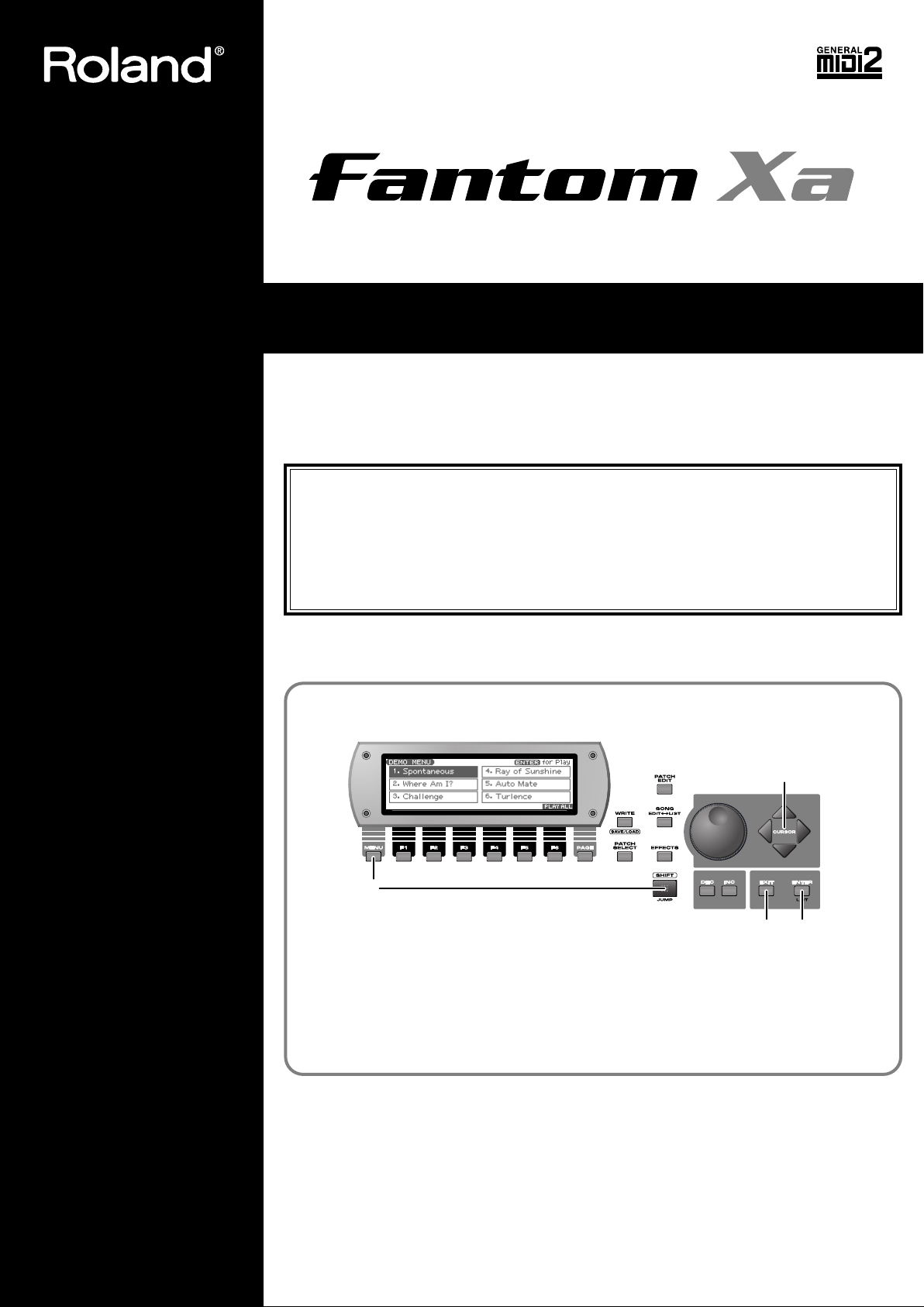
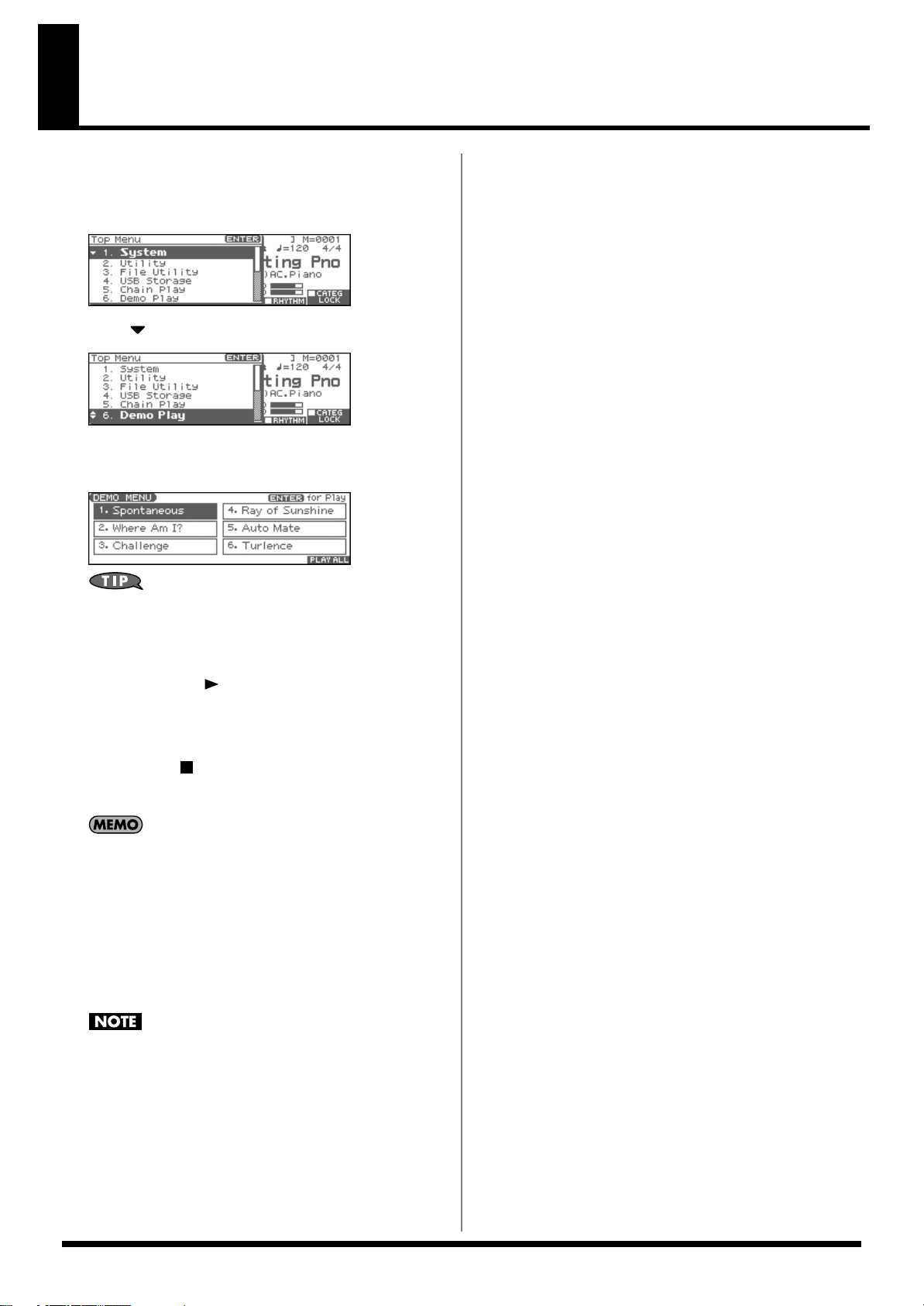
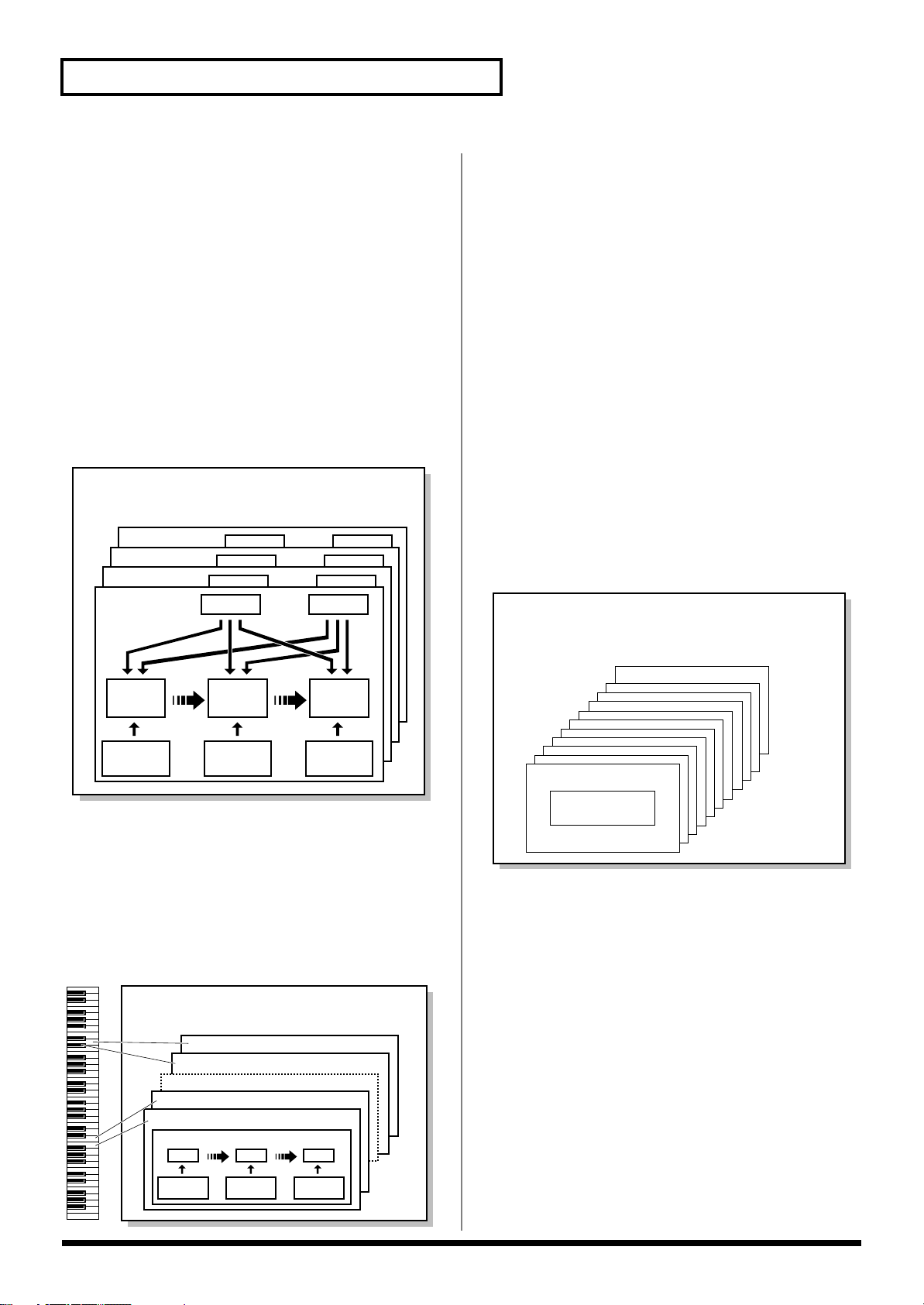
Listening to the Demo Song
fig.Cover.e
1. Hold down [SHIFT] and press [MENU].
2. Use [CURSOR] to select a song.
3. Press [ENTER] to start demo song playback.
To stop the song, press [EXIT].
2. Select
3. Play
Stop
1
Owner’s Manual
Thank you, and congratulations on your choice of the Roland Fantom-Xa.
985
* The explanations in this manual include illustrations that depict what should typically be shown by the display. Note, however, that your
unit may incorporate a newer, enhanced version of the system (e.g., includes newer sounds), so what you actually see in the display may
not always match what appears in the manual.
202
Copyright © 2004 ROLAND CORPORATION
All rights reserved. No part of this publication may be reproduced in any form without the
written permission of ROLAND CORPORATION.
Page 2
USING THE UNIT SAFELY
Used for instructions intended to alert
the user to the risk of death or severe
injury should the unit be used
improperly.
Used for instructions intended to alert
the user to the risk of injury or material
damage should the unit be used
improperly.
* Material damage refers to damage or
other adverse effects caused with
respect to the home and all its
furnishings, as well to domestic
animals or pets.
001
• Before using this unit, make sure to read the instructions below, and the Owner’s Manual.
..........................................................................................................
002d
• Do not open or perform any internal modifications on
the unit or its AC adaptor. (The only exception would be
where this manual provides specific instructions which
should be followed in order to put in place userinstallable options; see p. 214, p. 216.)
..........................................................................................................
003
• Do not attempt to repair the unit, or replace parts within
it (except when this manual provides specific instructions directing you to do so). Refer all servicing to your
retailer, the nearest Roland Service Center, or an authorized Roland distributor, as listed on the “Information”
page.
..........................................................................................................
004
• Never use or store the unit in places that are:
• Subject to temperature extremes (e.g., direct sunlight
in an enclosed vehicle, near a heating duct, on top of
heat-generating equipment); or are
• Damp (e.g., baths, washrooms, on wet floors); or are
• Humid; or are
• Exposed to rain; or are
• Dusty; or are
• Subject to high levels of vibration.
..........................................................................................................
005
• This unit should be used only with a rack or stand that
is recommended by Roland.
..........................................................................................................
006
• When using the unit with a rack or stand recommended
by Roland, the rack or stand must be carefully placed so
it is level and sure to remain stable. If not using a rack or
stand, you still need to make sure that any location you
choose for placing the unit provides a level surface that
will properly support the unit, and keep it from
wobbling.
..........................................................................................................
008c
• Be sure to use only the AC adaptor supplied with the
unit. Also, make sure the line voltage at the installation
matches the input voltage specified on the AC adaptor’s
body. Other AC adaptors may use a different polarity,
or be designed for a different voltage, so their use could
result in damage, malfunction, or electric shock.
..........................................................................................................
008e
• Use only the attached power-supply cord. Also, the
supplied power cord must not be used with any other
device.
..........................................................................................................
009
• Do not excessively twist or bend the power cord, nor
place heavy objects on it. Doing so can damage the cord,
producing severed elements and short circuits.
Damaged cords are fire and shock hazards!
..........................................................................................................
010
• This unit, either alone or in combination with an
amplifier and headphones or speakers, may be capable
of producing sound levels that could cause permanent
hearing loss. Do not operate for a long period of time at
a high volume level, or at a level that is uncomfortable.
If you experience any hearing loss or ringing in the ears,
you should immediately stop using the unit, and consult
an audiologist.
..........................................................................................................
2
Page 3
011
• Do not allow any objects (e.g., flammable material,
coins, pins); or liquids of any kind (water, soft drinks,
etc.) to penetrate the unit.
..........................................................................................................
012b
• Immediately turn the power off, remove the AC adaptor
from the outlet, and request servicing by your retailer,
the nearest Roland Service Center, or an authorized
Roland distributor, as listed on the “Information” page
when:
• The AC adaptor, the power-supply cord, or the plug
has been damaged; or
• If smoke or unusual odor occurs
• Objects have fallen into, or liquid has been spilled
onto the unit; or
• The unit has been exposed to rain (or otherwise has
become wet); or
• The unit does not appear to operate normally or
exhibits a marked change in performance.
..........................................................................................................
013
• In households with small children, an adult should
provide supervision until the child is capable of
following all the rules essential for the safe operation of
the unit.
..........................................................................................................
014
• Protect the unit from strong impact.
(Do not drop it!)
..........................................................................................................
015
• Do not force the unit’s power-supply cord to share an
outlet with an unreasonable number of other devices. Be
especially careful when using extension cords—the total
power used by all devices you have connected to the
extension cord’s outlet must never exceed the power
rating (watts/amperes) for the extension cord. Excessive
loads can cause the insulation on the cord to heat up and
eventually melt through.
..........................................................................................................
016
• Before using the unit in a foreign country, consult with
your retailer, the nearest Roland Service Center, or an
authorized Roland distributor, as listed on the “Information” page.
..........................................................................................................
022b
• Always turn the unit off and unplug the AC adaptor
before attempting installation of the circuit board (SRX
series; p. 214, DIMM; p. 216).
..........................................................................................................
023
• DO NOT play a CD-ROM disc on a conventional audio
CD player. The resulting sound may be of a level that
could cause permanent hearing loss. Damage to
speakers or other system components may result.
..........................................................................................................
101b
• The unit and the AC adaptor should be located so their
location or position does not interfere with their proper
ventilation.
..........................................................................................................
101c
• This unit for use only with Roland stand KS-12. Use
with other stands (or carts) is capable of resulting in
instability causing possible injury.
..........................................................................................................
102c
• Always grasp only the plug on the AC adaptor cord
when plugging into, or unplugging from, an outlet or
this unit.
..........................................................................................................
103b
• At regular intervals, you should unplug the AC adaptor
and clean it by using a dry cloth to wipe all dust and
other accumulations away from its prongs. Also,
disconnect the power plug from the power outlet
whenever the unit is to remain unused for an extended
period of time. Any accumulation of dust between the
power plug and the power outlet can result in poor
insulation and lead to fire.
..........................................................................................................
104
• Try to prevent cords and cables from becoming
entangled. Also, all cords and cables should be placed
so they are out of the reach of children.
..........................................................................................................
106
• Never climb on top of, nor place heavy objects on the
unit.
..........................................................................................................
107c
• Never handle the AC adaptor or its plugs with wet
hands when plugging into, or unplugging from, an
outlet or this unit.
..........................................................................................................
108b
• Before moving the unit, disconnect the AC adaptor and
all cords coming from external devices.
..........................................................................................................
109b
• Before cleaning the unit, turn off the power and unplug
the AC adaptor from the outlet (p. 16).
..........................................................................................................
110b
• Whenever you suspect the possibility of lightning in
your area, disconnect the AC adaptor from the outlet.
..........................................................................................................
115a
• Install only the specified circuit board (SRX series,
DIMM). Remove only the specified screws (p. 214, p.
216).
..........................................................................................................
118a
• Should you remove the ground terminal screw or
screws that fasten the bottom cover or the PC card
protector, keep them in a safe place out of children’s
reach, so there is no chance of them being swallowed
accidentally.
..........................................................................................................
3
Page 4

IMPORTANT NOTES
291a
In addition to the items listed under “USING THE UNIT SAFELY” on pages 2–3, please read and observe the following:
Power Supply
301
• Do not connect this unit to same electrical outlet that is being
used by an electrical appliance that is controlled by an inverter
(such as a refrigerator, washing machine, microwave oven, or air
conditioner), or that contains a motor. Depending on the way in
which the electrical appliance is used, power supply noise may
cause this unit to malfunction or may produce audible noise. If it
is not practical to use a separate electrical outlet, connect a power
supply noise filter between this unit and the electrical outlet.
302
• The AC adaptor will begin to generate heat after long hours of
consecutive use. This is normal, and is not a cause for concern.
307
• Before connecting this unit to other devices, turn off the power to
all units. This will help prevent malfunctions and/or damage to
speakers or other devices.
Placement
351
• Using the unit near power amplifiers (or other equipment
containing large power transformers) may induce hum. To
alleviate the problem, change the orientation of this unit; or move
it farther away from the source of interference.
352a
• This device may interfere with radio and television reception. Do
not use this device in the vicinity of such receivers.
352b
• Noise may be produced if wireless communications devices, such
as cell phones, are operated in the vicinity of this unit. Such noise
could occur when receiving or initiating a call, or while
conversing. Should you experience such problems, you should
relocate such wireless devices so they are at a greater distance
from this unit, or switch them off.
354a
• Do not expose the unit to direct sunlight, place it near devices
that radiate heat, leave it inside an enclosed vehicle, or otherwise
subject it to temperature extremes. Excessive heat can deform or
discolor the unit.
355b
• When moved from one location to another where the temperature and/or humidity is very different, water droplets (condensation) may form inside the unit. Damage or malfunction may
result if you attempt to use the unit in this condition. Therefore,
before using the unit, you must allow it to stand for several
hours, until the condensation has completely evaporated.
358
• Do not allow objects to remain on top of the keyboard. This can
be the cause of malfunction, such as keys ceasing to produce
sound.
Maintenance
401a
• For everyday cleaning wipe the unit with a soft, dry cloth or one
that has been slightly dampened with water. To remove stubborn
dirt, use a cloth impregnated with a mild, non-abrasive detergent.
Afterwards, be sure to wipe the unit thoroughly with a soft, dry
cloth.
402
• Never use benzine, thinners, alcohol or solvents of any kind, to
avoid the possibility of discoloration and/or deformation.
Repairs and Data
452
• Please be aware that all data contained in the unit’s memory may
be lost when the unit is sent for repairs. Important data should
always be backed up on a memory card, or written down on
paper (when possible). During repairs, due care is taken to avoid
the loss of data. However, in certain cases (such as when circuitry
related to memory itself is out of order), we regret that it may not
be possible to restore the data, and Roland assumes no liability
concerning such loss of data.
Additional Precautions
551
• Please be aware that the contents of memory can be irretrievably
lost as a result of a malfunction, or the improper operation of the
unit. To protect yourself against the risk of loosing important
data, we recommend that you periodically save a backup copy of
important data you have stored in the unit’s memory on a
memory card, or other device.
552
• Unfortunately, it may be impossible to restore the contents of
data that was stored on a memory card, unit’s memory, or other
device once it has been lost. Roland Corporation assumes no
liability concerning such loss of data.
553
• Use a reasonable amount of care when using the unit’s buttons,
sliders, or other controls; and when using its jacks and
connectors. Rough handling can lead to malfunctions.
554
• Never strike or apply strong pressure to the display.
556
• When connecting / disconnecting all cables, grasp the connector
itself—never pull on the cable. This way you will avoid causing
shorts, or damage to the cable’s internal elements.
558a
• To avoid disturbing your neighbors, try to keep the unit’s volume
at reasonable levels. You may prefer to use headphones, so you
do not need to be concerned about those around you (especially
when it is late at night).
559a
• When you need to transport the unit, package it in the box
(including padding) that it came in, if possible. Otherwise, you
will need to use equivalent packaging materials.
561
• Use only the specified expression pedal (EV-5; sold separately).
By connecting any other expression pedals, you risk causing
malfunction and/or damage to the unit.
562
• Use a cable from Roland to make the connection. If using some
other make of connection cable, please note the following precautions.
• Some connection cables contain resistors. Do not use cables
that incorporate resistors for connecting to this unit. The use
of such cables can cause the sound level to be extremely low,
or impossible to hear. For information on cable specifications,
contact the manufacturer of the cable.
566a
• The usable range of D Beam controller will become extremely
small when used under strong direct sunlight. Please be aware of
this when using the D Beam controller outside.
566b
• The sensitivity of the D Beam controller will change depending
on the amount of light in the vicinity of the unit. If it does not
function as you expect, adjust the sensitivity as appropriate for
the brightness of your location.
4
Page 5
Before Using Cards
Using Memory Cards
704
• Carefully insert the memory card all the way in—until it is firmly
in place.
705
• Never touch the terminals of the memory card. Also, avoid
getting the terminals dirty.
707
• This unit’s memory card slot accepts CompactFlash or SmartMedia (3.3 V). Microdrive storage media are not compatible.
708
• CompactFlash and SmartMedia (3.3 V) cards are constructed
using precision components; handle the cards carefully, paying
particular note to the following.
• To prevent damage to the cards from static electricity, be sure
to discharge any static electricity from your own body before
handling the cards.
• Do not touch or allow metal to come into contact with the
contact portion of the cards.
• Do not bend, drop, or subject cards to strong shock or
vibration.
• Do not keep cards in direct sunlight, in closed vehicles, or
other such locations (storage temperature: -25 to 85˚ C).
• Do not allow cards to become wet.
• Do not disassemble or modify the cards.
IMPORTANT NOTES
Handling CD-ROMs
801
• Avoid touching or scratching the shiny underside (encoded
surface) of the disc. Damaged or dirty CD-ROM discs may not be
read properly. Keep your discs clean using a commercially
available CD cleaner.
Copyright
851
• Unauthorized recording, distribution, sale, lending, public
performance, broadcasting, or the like, in whole or in part, of a
work (musical composition, video, broadcast, public performance, or the like) whose copyright is held by a third party is
prohibited by law.
853
• Do not use this unit for purposes that could infringe on a
copyright held by a third party. We assume no responsibility
whatsoever with regard to any infringements of third-party
copyrights arising through your use of this unit.
220
* All product names mentioned in this document are trademarks or
registered trademarks of their respective owners.
230
* SmartMedia is a trademark of Toshiba Corp.
234
* CompactFlash and are trademarks of SanDisk Corpo-
ration and licensed by CompactFlash association.
235
* Roland Corporation is an authorized licensee of the
CompactFlash™ and CF logo ( ) trademarks.
237
* V-LINK ( ) is a trademark of Roland Corpo-
ration.
5
Page 6

Contents
USING THE UNIT SAFELY......................................................................2
IMPORTANT NOTES ...............................................................................4
Main Features........................................................................................11
Panel Descriptions................................................................................12
Front Panel................................................................................................................................................. 12
Rear Panel.................................................................................................................................................. 14
Getting Ready........................................................................................15
Connections............................................................................................................................................... 15
Turning On/Off the Power..................................................................................................................... 16
Adjusting the Display Contrast (LCD Contrast).................................................................................. 16
Listening to the Demo Songs ..............................................................17
Various Performance Features............................................................18
Overview of the Fantom-Xa..................................................................19
How the Fantom-Xa Is Organized ......................................................................................................... 19
About Memory.......................................................................................................................................... 21
About the Onboard Effects ..................................................................................................................... 22
About the Sequencer................................................................................................................................ 23
About the Sampling Section.................................................................................................................... 25
Basic Operation of the Fantom-Xa ......................................................26
Switching the Sound Generator Mode ..................................................................................................26
About the Function Buttons.................................................................................................................... 26
Moving the Cursor ................................................................................................................................... 27
Changing a Value ..................................................................................................................................... 27
Assigning a Name ....................................................................................................................................28
Playing in Patch Mode..........................................................................29
About the PATCH PLAY Screen............................................................................................................ 29
Selecting a Patch .......................................................................................................................................30
Selecting Patches from the List............................................................................................................... 30
Selecting Favorite Patches/Rhythm Sets (Favorite Patch) .................................................................31
Selecting Patches by Category................................................................................................................ 32
Transposing the Keyboard in Octave Units (Octave Shift) ................................................................ 33
Transposing the Keyboard in Semitone Steps (Transpose)................................................................ 33
Selecting the Tones That Will Sound (Tone On/Off).......................................................................... 33
Playing Single Notes (Monophonic)...................................................................................................... 34
Creating Smooth Pitch Changes (Portamento) ....................................................................................34
Playing Percussion Instruments............................................................................................................. 34
Selecting the Parameter Controlled by the Realtime Controllers or D Beam Controller
(Control Setting) .......................................................................................................................................34
Creating a Patch....................................................................................35
How to Make Patch Settings................................................................................................................... 35
Saving Patches You’ve Created (Write) ................................................................................................37
Functions of Patch Parameters ...............................................................................................................38
6
Page 7

Contents
Creating a Rhythm Set .........................................................................55
How to Make Rhythm Set Settings........................................................................................................ 55
Saving Rhythm Sets You’ve Created (Write) .......................................................................................57
Functions of Rhythm Set Parameters .................................................................................................... 58
Playing in Performance Mode..............................................................66
Displaying PERFORM LAYER Screen .................................................................................................. 66
Displaying PERFORM MIXER Screen................................................................................................... 66
Functions in the PERFORMANCE LAYER/MIXER Screen .............................................................. 66
Selecting a Performance........................................................................................................................... 67
Using the LAYER Screen......................................................................................................................... 68
Combining and Playing Sounds Together (Layer).............................................................................. 69
Playing Different Sounds in Different Areas of the Keyboard (Split) ..............................................69
Using the MIXER Screen .........................................................................................................................70
Silencing the Playback of a Specific Part (Mute).................................................................................. 71
Creating a Performance .......................................................................72
Adjusting the Parameters of Each Part ................................................................................................. 72
Changing the Settings of the Patch Assigned to a Part....................................................................... 72
Saving a Performance You’ve Created (Write) .................................................................................... 72
Functions of Parameters of Each Part (Performance Parameters)..................................................... 73
Settings for the Realtime Controllers and D Beam Controller........................................................... 78
MIDI Settings ............................................................................................................................................79
Modifying the Sound in Real Time ......................................................80
D Beam Controller.................................................................................................................................... 80
Realtime Controller ..................................................................................................................................83
Control Pedal ............................................................................................................................................ 85
Playing Arpeggios ................................................................................86
About Arpeggio........................................................................................................................................ 86
Playing Arpeggios.................................................................................................................................... 86
Arpeggio Settings ..................................................................................................................................... 87
Creating an Arpeggio Style (Arpeggio Style Edit) ..............................................................................90
Saving the Styles You Have Created (Write)........................................................................................ 91
Using the Chord Memory Function .....................................................92
About the Chord Memory Function...................................................................................................... 92
Performing with the Chord Memory Function.................................................................................... 92
Creating Your Own Chord Forms .........................................................................................................93
Saving the Chord Forms You Have Created........................................................................................ 93
Playing Rhythms...................................................................................94
About Rhythm Patterns........................................................................................................................... 94
Using Rhythm Groups............................................................................................................................. 94
Playing Rhythm ........................................................................................................................................94
Rhythm Pattern Settings.......................................................................................................................... 96
Creating a Rhythm Pattern (Rhythm Pattern Edit) ............................................................................. 97
Saving the Rhythm Pattern You Have Created (Write)...................................................................... 98
Creating a Rhythm Group (Rhythm Group Edit)................................................................................ 99
Saving the Rhythm Group You Have Created (Write)....................................................................... 99
7
Page 8

Contents
Sampling..............................................................................................100
Sampling Procedure............................................................................................................................... 100
External Input Settings ..........................................................................................................................101
Skip Back Sampling................................................................................................................................ 103
Editing a Sample .................................................................................104
Sample List .............................................................................................................................................. 104
Sample Edit ............................................................................................................................................. 106
Assigning Samples to a Pad (Assign to Pad)...................................................................................... 112
Assigning a Sample as a Patch to a Part (Assign to Keyboard)....................................................... 113
Create a Rhythm Set (Create Rhythm) ................................................................................................ 114
Creating a Multisample (Create Multisample) ..................................................................................114
Saving a Sample (Write) ........................................................................................................................ 116
Using the Pads ....................................................................................117
Using the Hold Function to Sustain a Sound ..................................................................................... 117
Making Settings for the Pads (Pad Setting) ........................................................................................ 117
Assigning a Pattern to a Pad (RPS Function) .....................................................................................118
Using the Pads to Play Rhythms.......................................................................................................... 118
Playing Back a Song...........................................................................119
Playing a Song Immediately (Quick Play).......................................................................................... 119
Playing Back Songs Consecutively (Chain Play) ............................................................................... 119
Various Playback Methods ...................................................................................................................120
Recording Songs ................................................................................122
Before You Record a New Song ...........................................................................................................122
Recording Your Performance as You Play It (Realtime Recording) ...............................................124
Inputting Data One Step at a Time (Step Recording)........................................................................ 128
Editing Songs......................................................................................131
Loading the Song You Want to Edit ....................................................................................................131
Editing Sequencer Data Over the Specified Range (Track Edit) ..................................................... 133
Editing Individual Items of Sequencer Data (Micro Edit)................................................................ 144
Assigning a Name to a Song (Song Name)......................................................................................... 149
Saving/Loading a Song (Save/Load).................................................150
Saving a Song (Save) .............................................................................................................................. 150
Saving a Song as an SMF File (Save as SMF)...................................................................................... 152
Loading a Song (Load)........................................................................................................................... 153
Playing a Phrase at the Touch of a Finger (RPS).............................154
Before You Use the RPS Function ........................................................................................................ 154
Using the RPS Function While You Perform...................................................................................... 156
8
Page 9

Contents
Adding Effects.....................................................................................157
Turning Effects On and Off................................................................................................................... 157
Making Effect Settings ........................................................................................................................... 157
Applying Effects in Patch Mode .......................................................................................................... 158
Applying Effects in Performance Mode.............................................................................................. 160
Making Multi-Effects Settings (MFX1–3)............................................................................................ 162
Making Multi-Effects Settings (MFX Control) ...................................................................................162
Specifying the Multi-Effects Structure (MFX Structure)................................................................... 163
Multi-Effects Parameters .......................................................................................................................164
Making Chorus Settings ........................................................................................................................ 189
Making Reverb Settings......................................................................................................................... 190
Mastering Effect...................................................................................................................................... 191
Settings Common to All Modes (System Function) ........................192
How to Make System Function Settings ............................................................................................. 192
Saving the System Settings (System Write) ........................................................................................ 192
System Information................................................................................................................................ 192
Functions of System Parameters ..........................................................................................................193
Data Management Functions/
Reset to Factory Settings (Factory Reset) .......................................203
Backing Up User Data (User Backup) .................................................................................................203
Restoring User Data that You Backed Up (User Restore) ................................................................ 203
Factory Reset ........................................................................................................................................... 203
Initializing a Memory Card (Card Format) ........................................................................................ 203
File-Related Functions (File Utility)...................................................204
Basic Procedure....................................................................................................................................... 204
Copying a File (Copy)............................................................................................................................ 205
Deleting a File (Delete) .......................................................................................................................... 205
Moving a File (Move)............................................................................................................................. 205
Initializing a Memory Card (Card Format) ........................................................................................ 205
Connecting to Your Computer via USB ............................................206
About USB Functions............................................................................................................................. 206
Switching the USB Storage Mode and the MIDI Mode .................................................................... 206
Transferring Files to or from Your Computer (Storage Mode) ....................................................... 207
Exchanging MIDI Messages with Your Computer (MIDI Mode)................................................... 209
Using Fantom-X Editor .......................................................................210
Installing Fantom-X Editor into Your Computer............................................................................... 210
Making Connections .............................................................................................................................. 210
Using Fantom-X Librarian .................................................................................................................... 210
Fantom-X Editor System Requirements.............................................................................................. 211
About V-LINK.......................................................................................212
What is V-LINK? .................................................................................................................................... 212
Connection Example .............................................................................................................................. 212
Turning the V-LINK ON/OFF ............................................................................................................. 212
V-LINK Settings...................................................................................................................................... 212
9
Page 10

10
Page 11

Main Features
The Fantom-Xa is a high-quality workstation synthesizer that makes
pro-quality sound, playability, and compositional power available to
everyone. The latest sound generator, versatile effects, a powerful
sequencer, and a sampler that lets you record, process and play
vocals or audio phrases—all brought together in a user-friendly
system. The features listed below make the Fantom-Xa a great choice
for any style of music, in applications ranging from stage
performance to composition and arranging.
The latest sound engine with 128voice polyphony
The Fantom-Xa provides 128 voices of polyphony—the standard for
the new era. You’ll have plenty of power for multitrack sequencer
recording and for layering complex sounds. The sound engine melds
the latest synthesizer technology with a sampler. Sampled
waveforms imported from your computer or other external device
can be synthesized just like the internal waveforms.
Highly expandable waveform
memory
To supplement the Fantom-Xa’s numerous new patches created
from the carefully selected high-quality built-in waveforms, you can
install one wave expansion board. Depending on your needs and
your favorite musical styles, you can choose one board from the
wide variety of professionally acclaimed Roland SRX series boards
now available.
The sampler section provides 4 MB (approximately 47 seconds in
monaural) of memory as standard, letting you sample immediately
without having to install any options. You can install optional
DIMM memory (up to 512 MB) to expand the sampling time to up to
one and a half hours (monaural).
A full-fledged sampler section with
Skip Back Sampling
The Fantom-Xa provides serious sampler functionality that rivals
dedicated units, with sampling, resampling, and waveform editing
in a graphic display.
Roland’s proprietary Skip Back Sampling function lets you
“retrospectively” capture a cool phrase that just played and would
like to keep. Your inspired moments need never be lost again!
There’s also an Auto Sync function, which matches a phrase sample
to the measure length at the current tempo, and a Solo Sampling
function, which lets you sample only an external vocal or guitar
performance while listening to an accompaniment played by the
internal sequencer. Both WAV and AIFF are supported as external
wave formats, making it easy to transfer waveform data to and from
PC or Mac.
Plenty of external interfacing
Built-in high-resolution 16-track
sequencer
The internal 16-track sequencer lets you record as soon as inspiration
strikes—no need to think about entering any complex sequencer
modes. Loop Recording lets you record each part without stopping,
and you can use the Part Track buttons to quickly select each part
and switch it on/off. The Fantom-Xa is designed to let your creative
imagination flow freely into songs. In addition, songs you created on
your computer-based sequencer (SMF format) can be transferred via
PC card or USB into the Fantom-Xa, and used to play backing tracks
while you play live on stage.
Trigger/Category pads
The Trigger/Category pads are a convenient feature that can also be
used as a numeric key pad. You can use them to play percussion
sounds or hits during a live performance, to trigger Realtime Phrase
Sequences (RPS), or you can assign the pads to play skipbacksampled audio phrases.
Powerful effects including
mastering functionality
The Fantom-Xa provides three multi-effects processors (78 types),
plus independent chorus and reverb processors. There’s a mastering
effect, indispensable for adding the final touch to your production,
bringing your sound CD-master level impact and audio quality.
Versatile sound control
functionality
The versatile array of controllers includes a D Beam controller as
well as realtime control knobs and assignable switches to which you
can freely assign functions. There’s also a hold pedal jack that can
detect half-damper operation. The Fantom-Xa gives you complete
control over your on-stage sound.
Fantom-X Editor/Librarian is
included
Dedicated editor/librarian software is included, letting you edit and
manage Fantom-Xa sounds from the large screen of your computer.
V-LINK functionality
V-LINK allows you to synchronize music and video, opening up
completely new performance possibilities.
When used in combination with a V-LINK capable video device
(such as the Edirol DV-7PR, PR-50, or V-4), you can use the realtime
controllers and pads of the Fantom-Xa to control video as part of the
act of playing music.
The rear panel USB connector supports both file transfer and USBMIDI, and can be switched as desired. There’s also a PC card slot
that can accommodate SmartMedia or CompactFlash via a
commercially available adaptor. You can use a card to store as much
as 1 GB of data (when using CompactFlash).
GM/GM2 compatibility
The Fantom-Xa is compatible with GM/GM2, and is able to play
back music data that complies with the GM/GM2 standard (GM
scores).
11
Page 12
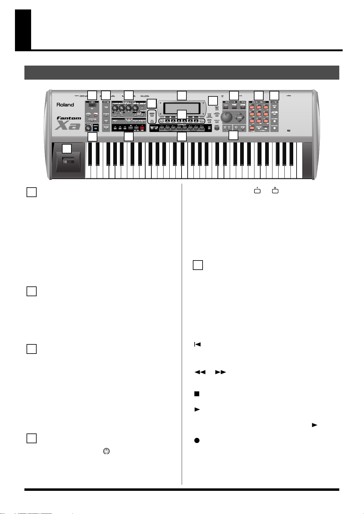
Panel Descriptions
Front Panel
fig.Front
3 4
1
7 11 13 14
6
10
8
2
5
15
1
D BEAM
Switches D Beam function on/off. You can apply a variety of effects
to sounds simply by moving your hand (p. 80).
[PAD TRIGGER]
You can use the D Beam controller to control the sounding of the
pads (p. 82).
[SOLO SYNTH]
Play the Fantom-Xa as a monophonic synthesizer (p. 81).
[ASSIGNABLE]
You can assign a variety of parameters and functions to D Beam to
modify the sound in realtime (p. 82).
* Hold down [SHIFT] and press one of the corresponding buttons to
access the D BEAM setting screen.
2
VOLUME knob
Adjusts the overall volume that is output from the rear panel
OUTPUT A (MIX) jacks and PHONES jack (p. 16).
[V-LINK]
Switches the V-LINK function on/off (p. 212).
Press this button to access the V-LINK setting screen.
3
ARP/RHY
BEAT (Beat Indicator)
This blinks in sync with the tempo and beat.
[ARPEGGIO]
Switches the ARPEGGIO on/off (p. 86).
[HOLD]
Switches the Arpeggio Hold function on/off (p. 87).
[RHYTHM]
Switches the RHYTHM on/off (p. 94).
* Hold down [SHIFT] and press [ARPEGGIO] or [RHYTHM] to
access ARPEGGIO or RHYTHM setting screen.
4
REALTIME CONTROL
REALTIME CONTROL knob ( )
Depending on the parameter or function that is assigned, you can
use the knobs to modify the sound in realtime (p. 83).
9
ASSIGNABLE switch ([ ], [ ])
Use these buttons to switch the assigned parameter or function to
modify the sound in realtime (p. 84).
* Hold down [SHIFT] and press (or rotate) one of the above switches (or
knobs) to access the corresponding setting screen.
[OCTAVE] (+/-)
Transposes the pitch of the keyboard in 1 octave units (-3– +3
octaves) (p. 33).
* Hold down [SHIFT] and press [OCTAVE] to transposes the pitch in
semitones (p. 33).
5
SEQUENCER
Perform sequencer operations such as playback and record.
[TEMPO]
Sets the tempo (BPM) (p. 120, p. 123).
[PATTERN]
Lets you edit or record patterns (p. 123, p. 124, p. 128).
[LOOP PLAY]
Turns Loop Play on/off (p. 121).
[ERASE/UNDO]
Cancels the most recent song edit or recording operation.
[]
Moves the song position to the top. If you press this during
playback, you will return to the beginning of the song and stop (p.
120).
[] []
Moves the song position to the first beat of the previous or next
measure (p. 120).
[]
Controls sequencer stop.
[]
Controls sequencer play.
* While stopped, you can hold down [SHIFT] and Press [ ] to
perform MIDI Update (p. 120).
[]
The display changes to the Recording Standby window. (p. 124, p.
128)
If you press this during recording, the Rehearsal function will be
activated (p. 127).
12
12
Page 13
Panel Descriptions
6
[CHORD MEMORY]
Switches the CHORD MEMORY on/off (p. 92).
[RPS]
Switches RPS on/off (p. 154).
* Hold down [SHIFT] and press [CHORD MEMORY] or [RPS] to
access the CHORD MEMORY or RPS setting screen.
7
Display
This displays information regarding the operation you are
performing.
8
[MENU]
Opens the MENU. The contents of the menu will depend on the
current mode.
Function buttons ([F1]–[F6])
During editing, these buttons execute a variety of functions, and
their function will differ depending on the screen.
[PAGE]
When this button is lit, you can use this to switch the screen.
* Hold down [SHIFT] and press [PAGE] to access the LCD Contrast
setting screen (p. 16).
9
PART/TRACK
[SELECT]
If you press this in Performance mode, buttons [1]–[8] will function
as Part Select buttons (p. 68, p. 70).
[MUTE]
If you press this in Performance mode, buttons [1]–[8] will function
as Mute buttons (p. 71, p. 120).
[1]–[4] (TONE SW [1]–[4])
In Performance mode, these correspond to parts 1–4 (9–12).
In Patch mode, they turn tones or waves on/off (p. 33).
[5]–[8] (TONE SELECT [1]–[4])
In Performance mode, these correspond to parts 5–8 (13–16).
In Patch mode, they select the tone or wave to edit (p. 35, p. 55).
[9-16]
If you press this in Performance mode so it’s lighted, buttons [1]–[8]
will correspond to parts 9–16.
11
[MIXER]
View the Performance mode’s Mixer screen (p. 70).
[LAYER/SPLIT]
View the Performance mode’s Layer screen (p. 68).
[PATCH/RHYTHM]
Enter Patch/Rhythm mode (p. 29).
12
VALUE Dial
This is used to modify values. If you hold down [SHIFT] as you turn
the VALUE dial, the value will change in greater increments.
[DEC], [INC]
This is used to modify values. If you keep on holding down one
button while pressing the other, the value change accelerates. If you
press one of these buttons while holding down [SHIFT], the value
will change in bigger increments (p. 27).
[CURSOR] ( , , , )
Moves the cursor location up/down/left/right (p. 27).
[EXIT]
Return to the previous screen, or close the currently open window.
In some screens, this causes the currently executing function to be
aborted.
[ENTER]
Use this button to execute an operation.
TRIGGER/CATEGORY
PAD [1]–[9]
Use these to play tones or samples, or to start patterns.
[HOLD] (PAD [0])
Turn “hold” (sustaining the sound after you release the pad) on/off
(p. 117).
[TRIGGER]
If you press this so it’s lighted, pads [1]–[9] will play tones or
samples.
[CATEGORY]
If you press this so it’s lighted, pads [0]–[9] will select patch
categories (p. 32)
* If you together press [TRIGGER] and [CATEGORY] so both are
lighted, you can use pads [0]–[9] as a numeric keypad to enter
numeric values (p. 27).
10
[WRITE]
Save edited settings into Temporary Area or a memory card (p. 37, p.
57, p. 72, p. 91, p. 93, p. 116, p. 150).
[PATCH SELECT]
View the PATCH SELECT screen (p. 31).
[PATCH EDIT]
Make patch-related settings (p. 35).
[SONG]
Make settings for song data and song edit (p. 119).
[EFFECTS]
Make effect-related settings (p. 157).
[SHIFT] (JUMP)
This button is used in conjunction with other buttons to execute
various functions.
SAMPLING
[MIX IN]
Switches the external input on/off (p. 101).
* Hold down [SHIFT] and press this button to access the INPUT
setting screen.
[SAMPLE]
View the SAMPLE EDIT or SAMPLE LIST screen (p. 104, p. 106).
[SAMPLING]
View the Sampling Menu screen (p. 100).
[SKIP BACK SAMPLING]
Sample the performance for a specified duration prior to the moment
you pressed the button (p. 103).
Pitch Bend/Modulation Lever
This allows you to control pitch bend or apply vibrato (p. 18).
13
Page 14
Panel Descriptions
Rear Panel
fig.Rear
Ground Terminal
927
Depending on the circumstances of a particular setup, you may
experience a discomforting sensation, or perceive that the surface
feels gritty to the touch when you touch this device, microphones
connected to it, or the metal portions of other objects, such as guitars.
This is due to an infinitesimal electrical charge, which is absolutely
harmless. However, if you are concerned about this, connect the
ground terminal (see figure) with an external ground. When the unit
is grounded, a slight hum may occur, depending on the particulars
of your installation. If you are unsure of the connection method,
contact the nearest Roland Service Center, or an authorized Roland
distributor, as listed on the “Information” page.
Unsuitable places for connection
• Water pipes (may result in shock or electrocution)
• Gas pipes (may result in fire or explosion)
• Telephone-line ground or lightning rod (may be dangerous in
the event of lightning)
POWER ON Switch
Press to turn the power on/off (p. 16).
DC IN Jack
Connect the AC adaptor here (p. 15).
Be sure to use only the supplied AC adaptor.
Cord Hook
Anchor the cord of the AC adaptor (p. 15).
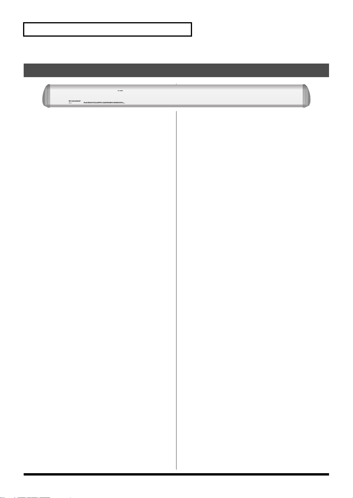
PC CARD Slot
A memory card can be inserted here (p. 218).
930
* Never insert or remove a memory card while this unit’s power is on.
Doing so may corrupt the unit’s data or the data on the memory card.
931
* Carefully insert the memory card all the way in—until it is firmly in
place.
USB Connector
This connector lets you use a USB cable to connect your computer to
the Fantom-Xa (p. 206).
CONTROL PEDAL Jack
You can connect optional expression pedals (EV-5, etc.) to these
jacks. By assigning a desired function to a pedal, you can use it to
select or modify sound or perform various other control. You can
also connect optional pedal switches (DP series etc.) to sustain sound
(p. 18).
925
* Use only the specified expression pedal (EV-5; sold separately). By
connecting any other expression pedals, you risk causing malfunction
and/or damage to the unit.
HOLD PEDAL Jack
An optional pedal switch (DP series etc.) can be connected to this
jack for use as a hold pedal (p. 18).
This can also be set so it supports the use of half-pedaling
techniques. So, after connecting an optional expression pedal (DP-8,
etc.), you can employ pedal work to achieve even finer control in
performances in which piano tones are used.
MIDI Connectors (IN, OUT, THRU)
These connectors can be connected to other MIDI devices to receive
and transmit MIDI messages.
LEVEL knob
Controls the volume of the external input.
AUDIO INPUT Jacks (L (MONO)/MIC, R)
Accept input of audio signals in stereo (L/R) from external devices.
If you want to use mono input, connect to the L jack.
When recording from a mic, connect it to the L jack, and set Input
Select (p. 100) to “MICROPHONE.”
926a
* When connection cables with resistors are used, the volume level of
equipment connected to the AUDIO INPUT jacks may be low. If this
happens, use connection cables that do not contain resistors, such as
those from the Roland PCS series.
OUTPUT A (MIX) Jacks (L (MONO), R)
These jacks output the audio signal to the connected mixer/amplifier
system in stereo. For mono output, use the L jack (p. 15).
OUTPUT B Jacks (L, R)
These jacks output the audio signal to the connected mixer/amplifier
system in stereo.
INDIVIDUAL 1-4 Jacks
These jacks output audio signals in mono to an amp or mixer.
The setting determining whether these jacks are used as stereo
OUTPUT jacks or monaural INDIVIDUAL jacks is made with the
Output Assign setting (p. 158, p. 160).
PHONES Jack
This is the jack for connecting headphones (sold separately) (p. 15).
14
Page 15
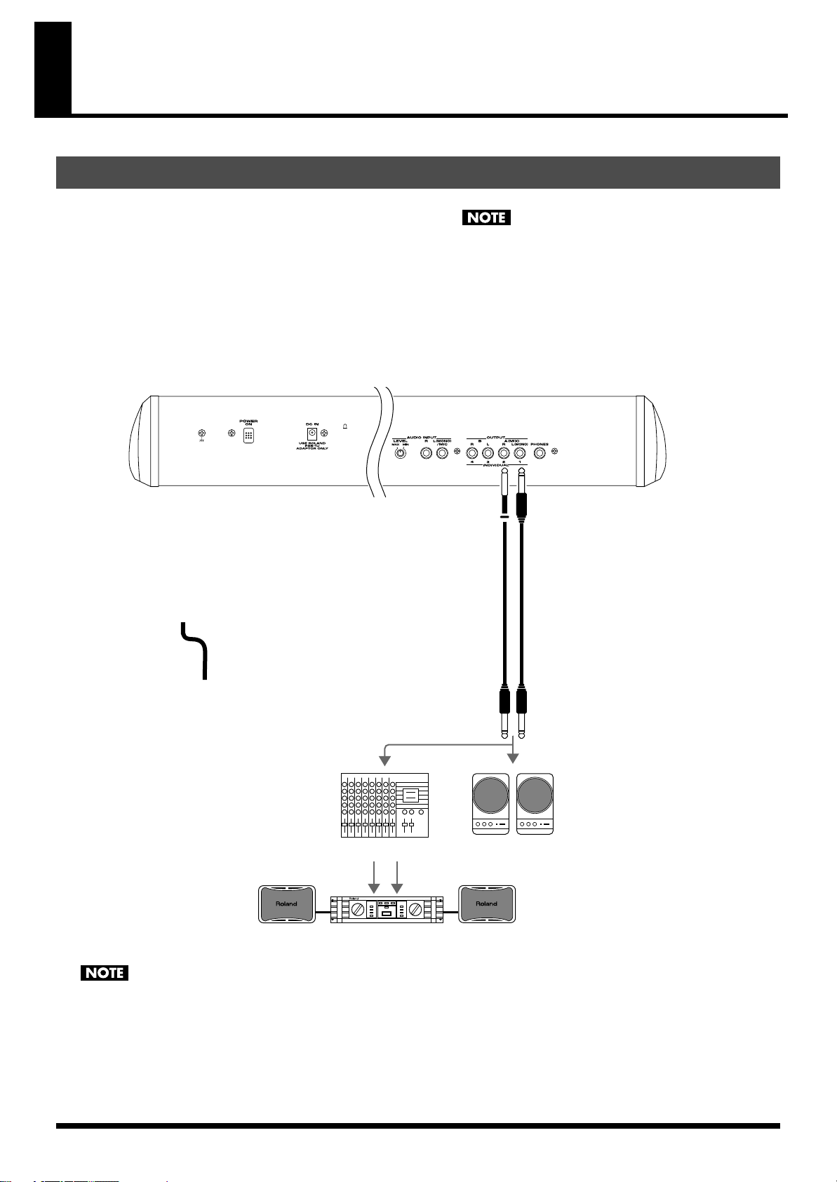
Getting Ready
Connections
Since Fantom-Xa contains no amplifier or speakers, you’ll need to
connect it to audio equipment such as a keyboard amplifier, monitor
speaker system or home stereo, or use headphones to hear its sound.
In order to fully experience the Fantom-Xa’s sound, we recommend
using a stereo amp/speaker system. If you’re using a mono system,
however, make your connections to the Fantom-Xa’s OUTPUT A
(MIX) jack L (MONO).
* Audio cables are not included with the Fantom-Xa. You’ll need to
provide them.
fig.Connect.e
921
To prevent malfunction and/or damage to speakers or other
devices, always turn down the volume, and turn off the power
on all devices before making any connections.
924
To prevent the inadvertent disruption of power to your unit
(should the plug be pulled out accidentally), and to avoid
applying undue stress to the AC adaptor jack, anchor the power
cord using the cord hook, as shown in the illustration.
15
Page 16
Getting Ready
Turning On/Off the Power
941
* Once the connections have been completed (p. 15), turn on power to
your various devices in the order specified. By turning on devices in
the wrong order, you risk causing malfunction and/or damage to
speakers and other devices.
Before turning on the Fantom-Xa’s power, consider these
1.
two questions:
• Are all devices connected properly?
• Have the volume controls of the Fantom-Xa and all connected
audio devices been turned to their lowest settings?
2.
Turn on the POWER ON switch located on the rear panel of
the Fantom-Xa.
fig.PowerOn
942
* This unit is equipped with a protection circuit. A brief interval (a few
seconds) after power up is required before the unit will operate
normally.
* To ensure proper operation of the pitch bend lever, make sure not to
touch the lever when turning the Fantom-Xa’s power on.
1.
Before turning off the power, consider these two questions:
• Have the volume controls of the Fantom-Xa and all connected
audio devices been turned to their lowest settings?
• Have you saved your Fantom-Xa sounds or other data you’ve
created?
2.
Turn off the power for all connected audio devices.
3.
Turn off the POWER ON switch of the Fantom-Xa.
The characters in the display may be difficult to view immediately
after turning on the Fantom-Xa’s power or after extended use. Your
viewing angle or the current lighting conditions can also affect the
appearance of the display. In such situations, adjust the contrast of
the display.
1.
Hold down [SHIFT] and press [PAGE] to open the LCD
Contrast window.
2.
Turn the VALUE dial to adjust the contrast.
* If you want to keep the contrast of the display, save the setting in
internal system memory (p. 192).
3.
Turn on the power for any connected audio devices.
While playing the keyboard, gradually raise the volume of
4.
the Fantom-Xa and connected devices.
fig.Volume
16
Page 17
Listening to the Demo Songs
The internal demo songs will feature the Fantom-Xa’s exceptional
sounds and effects.
1.
Press [MENU] to open the Top Menu Window.
fig.TopMenu
2.
Press to select “6. Demo Play.”
fig.DemoPlay
3.
Press [ENTER].
The DEMO MENU screen appears.
fig.DemoMenu
You can also access the DEMO MENU screen by holding down
[SHIFT] and pressing [MENU].
4.
Turn the VALUE dial or press [CURSOR] to select a song.
Press [ENTER] or [ ] to start playback.
5.
Playback will stop automatically when the song ends.
If you press [F6 (PLAY ALL)], the songs will playback
successively, beginning from the first.
* Press [EXIT] or [ ] to stop the demo song.
Press [EXIT] to return to the previous screen.
6.
For the names and copyright information of these demo songs,
refer to the Fantom-Xa’s display.
981a
* All rights reserved. Unauthorized use of this material for purposes
other than private, personal enjoyment is a violation of applicable
laws.
982
* No data for the music that is played will be output from MIDI OUT.
When you perform demo playback, any patch or performance
you may have been editing will be lost.
17
Page 18
Various Performance Features
Velocity
The velocity—the force with which you play the keyboard—can
affect the volume or timbre of a sound.
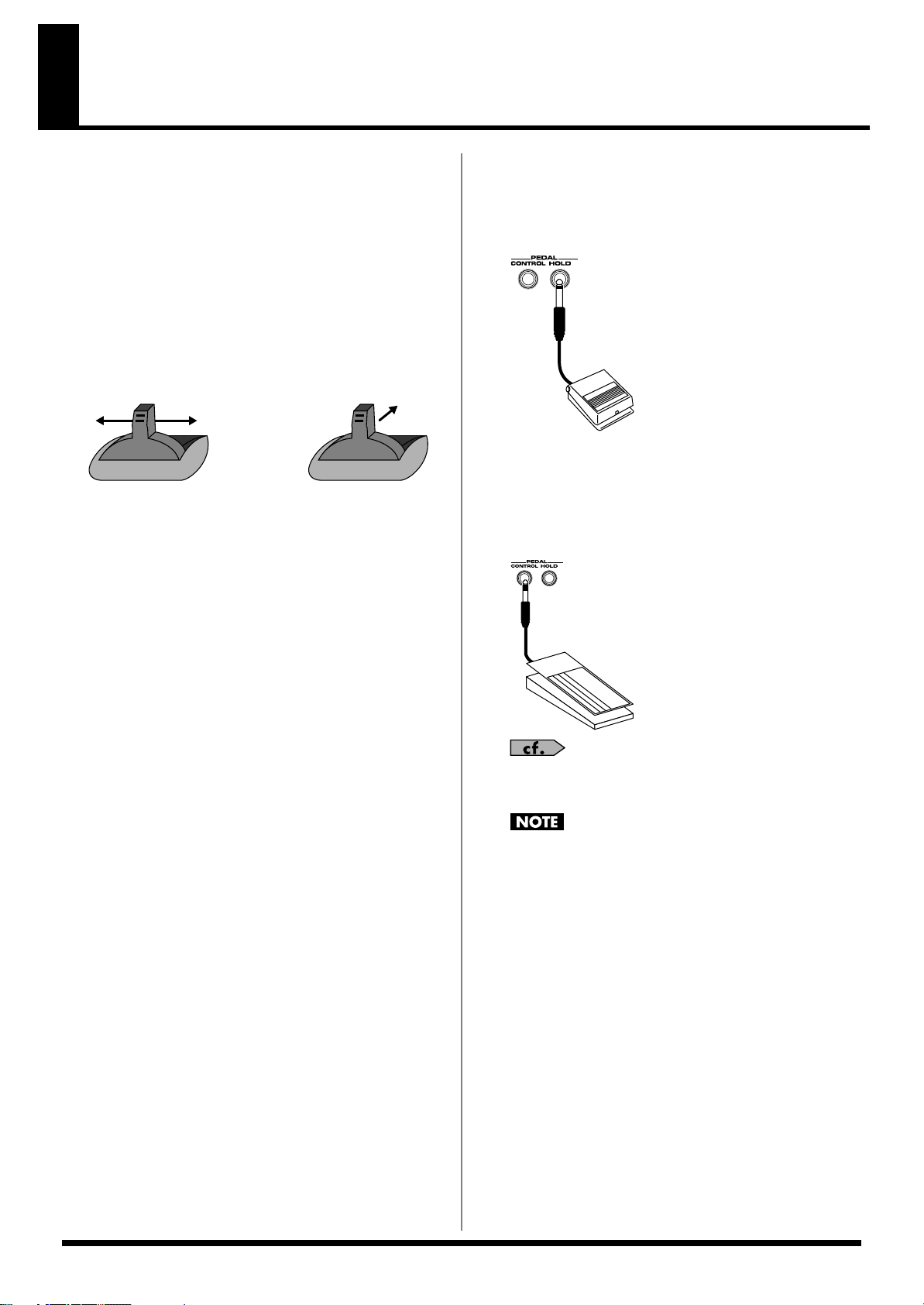
Pitch Bend/Modulation Lever
While playing the keyboard, move the lever to the left to lower the
pitch of the currently selected patch, or to the right to raise its pitch
(
pitch bend
away from you (
If you push the lever away from you and at the same time move it to
the right or left, you can apply both effects at once.
fig.Bender.e
). You can also apply vibrato by gently pushing the lever
modulation
).
ModulationPitch Bend
Octave Shift
You can shift the pitch of the keyboard in one-octave units over a
range of +/-3 octaves.
• Press OCTAVE [+] or [-] at the left of the screen.
• To return to the original pitch, press both buttons
simultaneously.
Hold Pedal
If an optional pedal switch (DP series) is connected to the rear panel
PEDAL HOLD jack, you can press the pedal to cause notes to sustain
or “hold” even after their keys have been released.
fig.HoldPdl
Control Pedal
If an optional expression pedal or pedal switch (EV-5, DP-2) is
connected to the rear panel PEDAL CONTROL jack, you can use the
pedal to control the volume or various function.
fig.CtrlPdl
Transpose
You can transpose the pitch of the keyboard in semitone steps, over a
range of G–F# (-5– +6 semitones).
• Hold down [SHIFT] and press OCTAVE [+] or [-].
• To return to the original pitch, hold down [SHIFT] and press
both buttons simultaneously.
For details on pedal settings, refer to
(p. 85).
925
Use only the specified expression pedal or pedal switch (EV-5,
DP-2; sold separately). By connecting any other expression
pedals, you risk causing malfunction and/or damage to the
unit.
Control Pedal Settings
18
Page 19
Overview of the Fantom-Xa
WG
Pitch
Envelope
TVF
TVF
Envelope
TVA
Envelope
TVA
LFO 1 LFO 2
control signal
Tone
audio signal
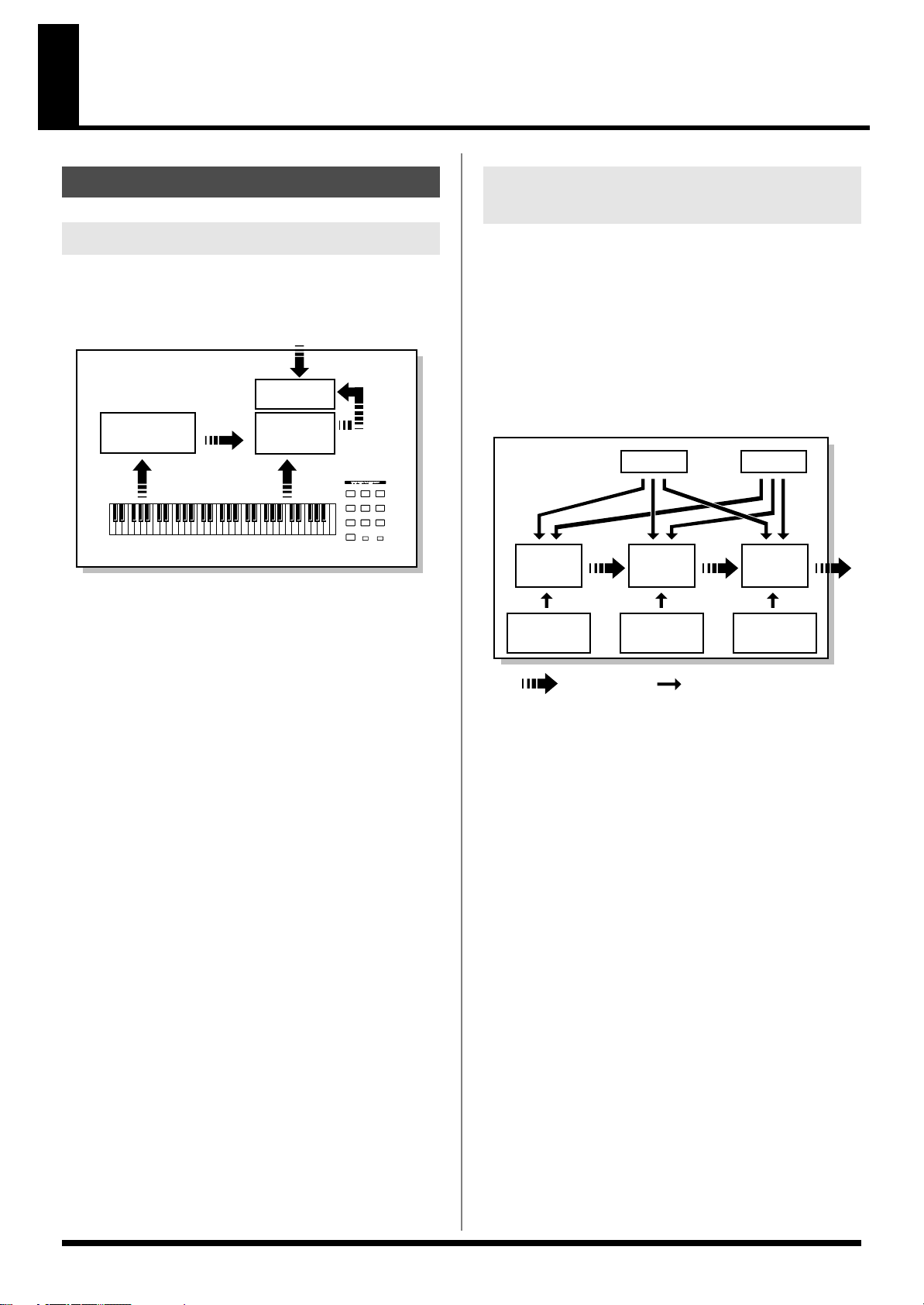
How the Fantom-Xa Is Organized
Basic Structure
Broadly speaking, the Fantom-Xa consists of a controller section, a
sound generator section, a sequencer section, and a sampler section.
These sections are internally connected via MIDI.
fig.BasicStruct.e
Sequencer
Section
Controller Section (controllers
such as keyboard, pad, pitch bend lever, etc.)
Playback
Recording
Audio Input
Sampler
Section
Sound
Generator
Section
Play
Sampling
Resampling
Controller Section
Classification of Fantom-Xa Sound Types
When using the Fantom-Xa, you will notice that a variety of different
categories come into play when working with sounds. What follows
is a simple explanation of each sound category.
Tones
On the Fantom-Xa, the tones are the smallest unit of sound.
However, it is not possible to play a tone by itself. The patch is the
unit of sound which can be played, and the tones are the basic
building blocks which make up the patch.
fig.Tone.e
This section consists of the keyboard, pad, pitch bend/modulation
lever, panel knobs and buttons, and D Beam controller. It also
includes any pedals that may be connected to the rear panel. The
performance information generated when you do things such as
press/release a key or pad, or depress the hold pedal is converted
into MIDI messages and sent to the sound generator section,
sequencer section, and/or an external MIDI device.
Sound Generator Section
The sound generator section produces the sound. It receives MIDI
messages from the controller section and sequencer section and/or
from an external MIDI device, generates musical sound according to
the MIDI messages that were received, and outputs the sound from
the output jacks or headphones jack.
Sequencer Section
This section records operations of the controller section as MIDI
messages, and transmits the recorded MIDI messages to the sound
generator section. MIDI messages recorded on the sequencer can
also be transmitted from the MIDI OUT connector to allow the
Fantom-Xa to also control external MIDI devices.
Sampler section
A sampler is a device that captures sounds from a CD player or mic
connected to the input (or sounds from a wave file) as “samples.”
Samples you record can be used in the same way as the waveforms
that are built into the internal sound generator (p. 100).
The Fantom-Xa can load WAV or AIFF format wave files as samples
via a USB connection. Loaded sample can be used in patches or
rhythm sets.
Tones consist of the following five components.
WG (Wave Generator)
Specifies the PCM waveform (wave) that is the basis of the sound,
and determines how the pitch of the sound will change.
The Fantom-Xa has 1228 different waveforms. All patches built into
the Fantom-Xa consist of combinations of tones which are created
based on these waveforms.
* There are four wave generators for each rhythm tone (percussion
instrument sounds).
TVF (Time Variant Filter)
Specifies how the frequency components of the sound will change.
TVA (Time Variant Amplifier)
Specifies the volume changes and the sound’s position in a stereo
soundfield.
Envelope
You use Envelope to initiate changes to occur to a sound over time.
There are separate envelopes for Pitch, TVF (filter), and TVA
(volume). For example if you wish to modify the way in which the
sound attacks or decays over time, you would adjust the TVA
envelope.
19
Page 20
Overview of the Fantom-Xa
Patch
Tone 4
Tone 3
Tone 2
Tone 1
WG
Pitch
Envelope
TVF
TVF
Envelope
TVA
Envelope
TVA
LFO 1 LFO 2
Performance
Part 16
Part 1
Patch/
Rhythm Set
LAYER/SPLIT
MIXER
LFO (Low Frequency Oscillator)
Use the LFO to create cyclic changes (modulation) in a sound. The
Fantom-Xa has two LFOs. You can use the LFO to apply an effect to
either the WG (pitch), the TVF (filter), or the TVA (volume). When
an LFO is applied to the WG pitch, a vibrato effect is produced.
When an LFO is applied to the TVF cutoff frequency, a wah effect is
produced. When an LFO is applied to the TVA volume, a tremolo
effect is produced.
* LFO is not included in the rhythm tones (percussion instrument
sounds).
Patches
Patches are the basic sound configurations that you play during a
performance. Each patch can be configured by combining up to four
tones. How the four tones are combined is determined by the
Structure Type parameter (p. 38).
fig.Patch.e
Each percussion instrument consists of the following four elements.
(For details, refer to the explanations for “Tones.”)
WG (Wave Generator): 1–4
TVF (Time Variant Filter)
TVA (Time Variant Amplifier)
Envelope
Performances
A performance has a patch or rhythm set assigned to each of the 16
parts, and can simultaneously handle 16 sounds.
The Fantom-Xa has two screens: a LAYER screen and a MIXER
screen (p. 68, p. 70).
Use the LAYER screen if you want to play two or more patches
together (Layer) or play different patches in separate areas of the
keyboard (Split).
Use the MIXER screen if you want to “mix” by individually
adjusting the pan and level settings for each of the sixteen parts.
Because the Fantom-Xa sound generator can control multiple sounds
(instruments), it is called a Multi-timbral sound generator.
fig.Performance.e
Rhythm Sets
Rhythm sets are groups of a number of different percussion
instrument sounds. Since percussion instruments generally do not
play melodies, there is no need for a percussion instrument sound to
be able to play a scale on the keyboard. It is, however, more
important that as many percussion instruments as possible be
available to you at the same time. Therefore, each key (note number)
of a rhythm set will produce a different percussion instrument.
fig.RhythmSet.e
20
Rhythm Set
Note Number 98 (D7)
Note Number 97 (C#7)
Note Number 36 (C2)
Note Number 35 (B1)
Rhythm Tone (Percussion instrument sound)
WG
Pitch
Envelope
TVF
TVF
Envelope
TVA
TVA
Envelope
Part
On the Fantom-Xa, a “part” is something to which you assign a
patch or rhythm set. Patch mode has two parts, the Pad part and the
Keyboard part, and you can assign a patch or rhythm set to each of
these parts. In Performance mode, each performance has sixteen
parts, and you can assign a patch or rhythm set to each part.
Page 21
Overview of the Fantom-Xa
Temporary Area
Rhythm Set
32
Patch
256
Select
Fantom-Xa
GM (GM2)
* 1 The selected Patches/Rhythm Sets cannot be changed.
Performance
64
User (USER)
System
WriteSelect
SelectWrite
Wave Expansion Board
Memory Card
Patch
256
Rhythm Set
32
Performance
64
Rhythm Set
Patch
EXP Slot
CARD Slot
Select Select
* 1
Patch
256
Rhythm Set
9
Performance
64
Rhythm Set
36
Patch
128
Preset B (PR-B)
Preset A (PR-A)
Preset C (PR-C)
Preset D (PR-D)
Preset F (PR-F)
Preset E (PR-E)
Preset (PRST)
About Simultaneous Polyphony
The Fantom-Xa can play a maximum of 128 sounds simultaneously.
The following paragraphs discuss what this means, and what will
happen when more than 128 simultaneous voices are requested from
the Fantom-Xa.
Calculating the Number of Voices
Being Used
The Fantom-Xa is able to play up to 128 notes simultaneously. The
polyphony, or the number of voices (sounds) does not refer only to
the number of patches actually being played, but changes according
to the number of tones used in the patches, and the number of waves
used in the tones. The following method is used to calculate the
number of sounds used for one patch being played.
(Number of patches being played) x (Number of tones used by
patches being played) x (Number of waves used in the tones)
For example, a patch that combines four tones, each of which use
two waves, will use eight notes of polyphony at once. Also, when
playing in Performance mode, the number of sounds for each part is
counted to obtain the total number of sounds for all parts.
How a Patch Sounds
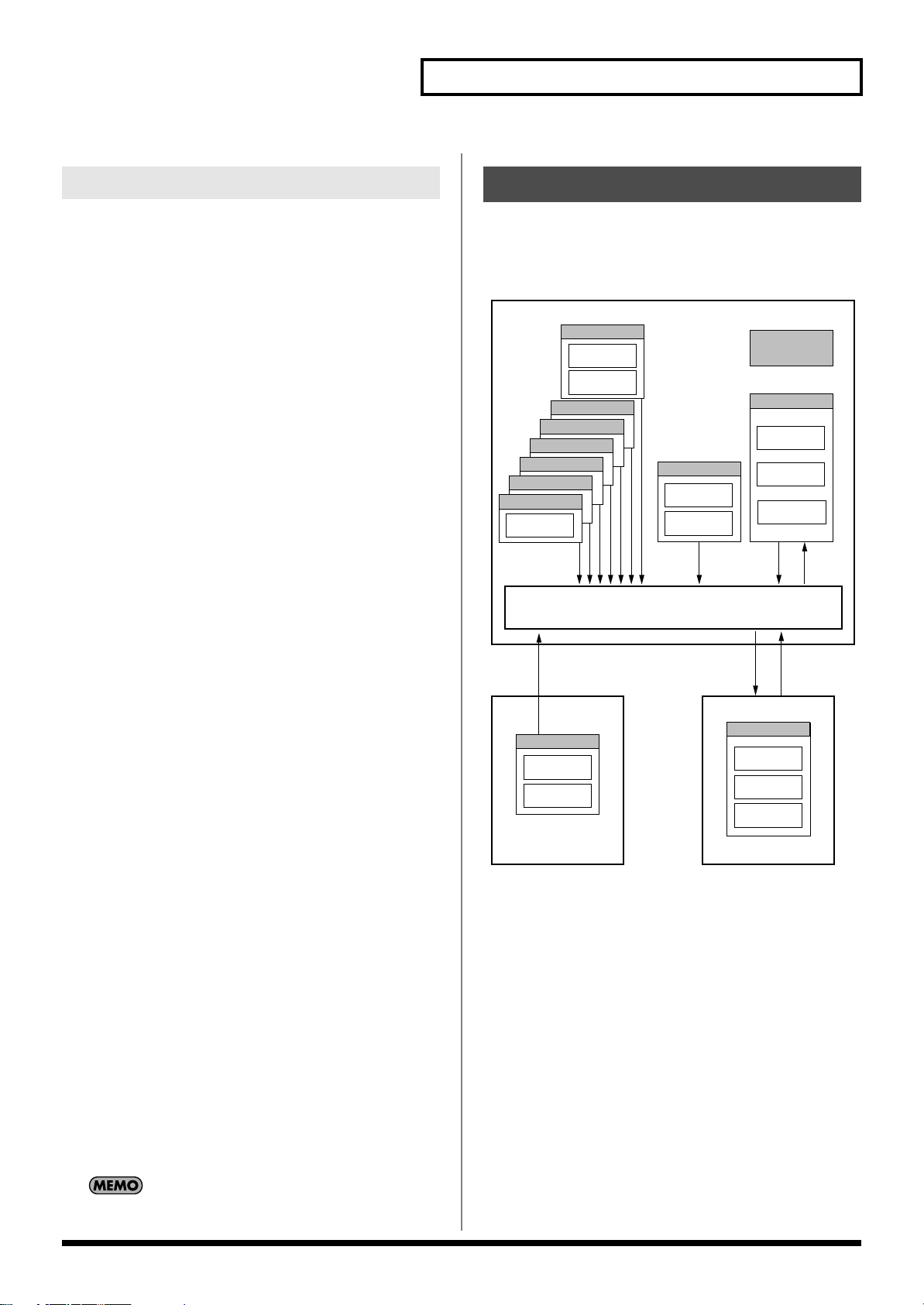
About Memory
Patch and performance settings are stored in what is referred to as
memory. There are three kind of memory: temporary, rewritable,
and non-rewritable.
fig.04-006.e
When the Fantom-Xa is requested to play more than 128 voices
simultaneously, currently sounding notes will be turned off to make
room for newly requested notes. The note with the lowest priority
will be turned off first. The order of priority is determined by the
Patch Priority setting (p. 40).
Patch Priority can be set either to “LAST” or “LOUDEST.” When
“LAST” is selected, a newly requested note that exceeds the 128
voice limit will cause the first-played of the currently sounding notes
to be turned off. When “LOUDEST” is selected, the quietest of the
currently sounding notes will be turned off. Usually, “LAST” is
selected.
Note Priority in Performance Mode
Since Performance mode is usually used to play an ensemble
consisting of several patches, it is important to decide which parts
take priority. Priority is specified by the Voice Reserve settings (p.
75). When a note within a patch needs to be turned off to make room
for a new note, the Patch Priority setting of the patch will apply (p.
40).
Voice Reserve
The Fantom-Xa has a Voice Reserve function that lets you reserve a
minimum number of notes that will always be available for each
part. For example if Voice Reserve is set to “10” for part 16, part 16
will always have 10 notes of sound-producing capacity available to it
even if a total of more than 128 notes (total for all parts) are being
requested. When you make Voice Reserve settings, you need to take
into account the number of notes you want to play on each part as
well as the number of tones used by the selected patch (p. 75).
It is not possible to make Voice Reserve settings that would
cause the total of all parts to be greater than 64 voices.
21
Page 22
Overview of the Fantom-Xa
Temporary Memory
Temporary Area
This is the area that holds the data for the patch or performance that
you’ve selected using the panel buttons.
When you play the keyboard or play back a sequence, sound is
produced based on data in the temporary area. When you edit a
patch or performance, you do not directly change the data in
memory; rather, you call up the data into the temporary area, and
edit it there.
Settings in the temporary area are temporary, and will be lost when
the power is turned off or when you select another patch/
performance. To keep the settings you have changed, you must write
them into rewritable memory.
Rewritable Memory
System Memory
System memory stores system parameter settings that determine
how the Fantom-Xa functions.
User Memory
User memory is the internal memory area that holds patches,
performances, samples, and performance data.
About the Onboard Effects
Effect Types
The Fantom-Xa has built-in effect units, and you can independently
edit each unit’s settings.
Multi-Effects
The multi-effects are multi-purpose effects that completely change
the sound type by changing the sound itself. Contained are 78
different effects types; select and use the type that suits your aims. In
addition to effects types composed of simple effects such as
Distortion, Flanger, and other such effects, you can also set up a
wide variety of other effects, even connecting effects in series or in
parallel. Furthermore, while chorus and reverb can be found among
the multi-effects types, the following chorus and reverb are handled
with a different system. In Performance mode, three types of multi-
effect can be used simultaneously; these are referred to as MFX1,
MFX2, and MFX3. In Patch mode, the Keyboard part can use MFX1
and the Pad part can use MFX2.
Chorus
Chorus adds depth and spaciousness to the sound. You can select
whether to use this as a chorus effect or a delay effect.
Memory Card
You can use a memory card to store patches, performances, samples,
and performance data just as you can in User memory.
Non-Rewritable Memory
Preset Memory
Data in Preset memory cannot be rewritten. However, you can call
up settings from preset memory into the temporary area, modify
them and then store the modified data in rewritable memory (except
GM2).
Wave Expansion Board
(SRX Series)
The Fantom-Xa can be equipped with a Wave Expansion Board (SRX
series; sold separately). Wave Expansion Boards contain Wave data,
as well as patches and rhythm sets that use this Wave data, which
can be called directly into the temporary area and played.
Reverb
Reverb adds the reverberation characteristics of halls or
auditoriums. Five different types are offered, so you can select and
use the type that suits your purpose.
Mastering Effect
This is a stereo compressor (limiter) that is applied to the final
output of the Fantom-Xa. It has independent high, mid, and low
ranges. Independently for the high-frequency, mid-frequency, and
low-frequency regions, this compresses any sounds that exceed the
specified level, making the volume more consistent.
22
Page 23

In Patch Mode
Multi-effects can be used individually by each patch and rhythm set.
Overview of the Fantom-Xa
23
Page 24
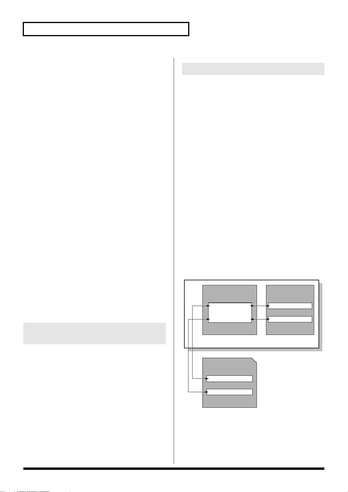
Overview of the Fantom-Xa
Tempo Track
The Tempo track records tempo changes of a song over time. It can
be used for tempo changes during a song. If a song has the same
tempo from beginning to end, the Tempo track can be ignored.
When a song is first recorded on the Fantom-Xa, a tempo setting at
the time of recording will be stored at the beginning of the Tempo
track. Therefore when song playback starts from the beginning, the
song will always play back at this initial tempo.
Thus playback tempo is determined by the Tempo track setting. If
you modify the tempo during playback, the overall tempo of the
song will be controlled by the setting you make.
Beat Track
The Beat track records the time signature of each measure of a song.
Set the Beat track when recording a new song, or when you want to
change time signature during a song.
Pattern
Patterns are a place to store performance data separately from
phrase tracks. You can create up to one hundred patterns; as with a
phrase track, each pattern can contain up to sixteen MIDI channels of
data.
Patterns can be assigned to phrase tracks. This means that if your
song uses repeating phrases such as drum or bass riffs, you can
record each phrase as a pattern, and then use the Step Recording
window to assign the patterns at the appropriate locations (p. 130).
In this case, the phrase track only contains “pattern call numbers”
which specify which pattern is to be played. This is convenient, and
also lets you conserve memory.
The RPS function (p. 154) for immediate playback also applies to
Patterns. Patterns are therefore convenient for live performance, if
you’ve recorded necessary sequencer data as Patterns and take them
to the gig.
Patterns also make fine scratch-pads for musical ideas.
Positions for Storing a Song
Temporary Area
The sequencer has an area called
temporarily store one song. So we call this
The song in Temporary Area is volatile and will be lost when the
power is turned off. To keep a song, you must save it to user
memory or memory card.
Temporary Area
temporary song
that can
.
Memory Card/User Memory
If you want to keep the song in Temporary Area that you recorded
or edited, you must save it as a song file onto a memory card or into
user memory. Either method lets you save up to 256 songs.
A card and user memory can contain two file types. The three-letter
symbol shown in parentheses ( ) is a file name extension that
distinguishes the different file types.
Song File (.SVQ)
This file is a song created on the Fantom-Xa. It is called an
song
.
Standard MIDI File (.MID)
Standard MIDI File
data to be exchanged between most musical applications. Fantom-Xa
files can be saved as Standard MIDI Files. This also allows you to
play back commercially available music data (GM scores) that is
compatible with the GM/GM2 system.
fig.SongFile.e
is a standard file format that allows sequencer
Temporary Memory
Temporary Area
User Memory
Song file
Standard MIDI file
MRC Pro
Songs and the Sound Generator Mode
The Fantom-Xa’s sequencer can be used at any time, regardless of
the mode of the sound generator (Patch/Performance).
In Performance mode you can use up to sixteen sounds, with each
part playing a different sound. This means that Performance mode is
ideal for recording or playing an ensemble that uses multiple
instruments, such as drums, bass, and piano.
In Patch mode you can play using the sounds that are assigned to the
Keyboard part and the Pad part.
24
Fantom-Xa
Memory Card
Song file
Standard MIDI file
Page 25
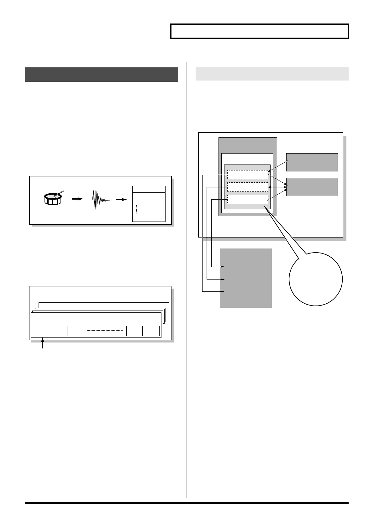
Overview of the Fantom-Xa
Sampler Section
User Bank
Preset Bank
Card Bank
Memory Card
Preset Memory
User Memory
Sample Memory
Fantom-Xa
Load
Load
Write
Load/Write
Write
Write
Write
Write
Sampling
About the Sampling Section
The Sampling section samples (records) external sounds from an
audio device or mic as digital data. Sampled sounds can be played as
a patch or rhythm set. You can also import WAV/AIFF format files
and use them in the same way.
Samples
A
sample
contains the waveform data sampled by the Fantom-Xa.
In addition to the actual waveform data itself, a sample also contains
parameters such as start point, loop start, and loop end. The Fantom-
Xa can hold 9,000 samples (User: 2000, Card: 7000).
fig.Sample.e
Sample
Sample List
User Sample
0001
0002
2000
Drum
Sampling
Wave
(Sample)
Added
automatically
Multisamples
Two or more samples assigned to the keyboard are collectively
called a multisample. A multisample is divided into 128 “splits.”
Each split contains the number of a sample in the sample list—it
does not contain the actual sample data itself.
fig.Multisample1.e
Multisample
Where Samples are Stored
Samples that you record or import are stored in sample memory.
This sample memory is temporary, and its data will be lost when
you turn off the power. If you want to keep these samples, you must
save them to user memory or a memory card.
* You cannot save data to the preset memory.
fig.SampleMemory.e
sample
sample
No.001
No.002
Number in the sample list
No.001Multisample
sample
No.003
No.128Multisample
sample
No.127
A multisample is
divided into 128
sample
No.128
25
Page 26
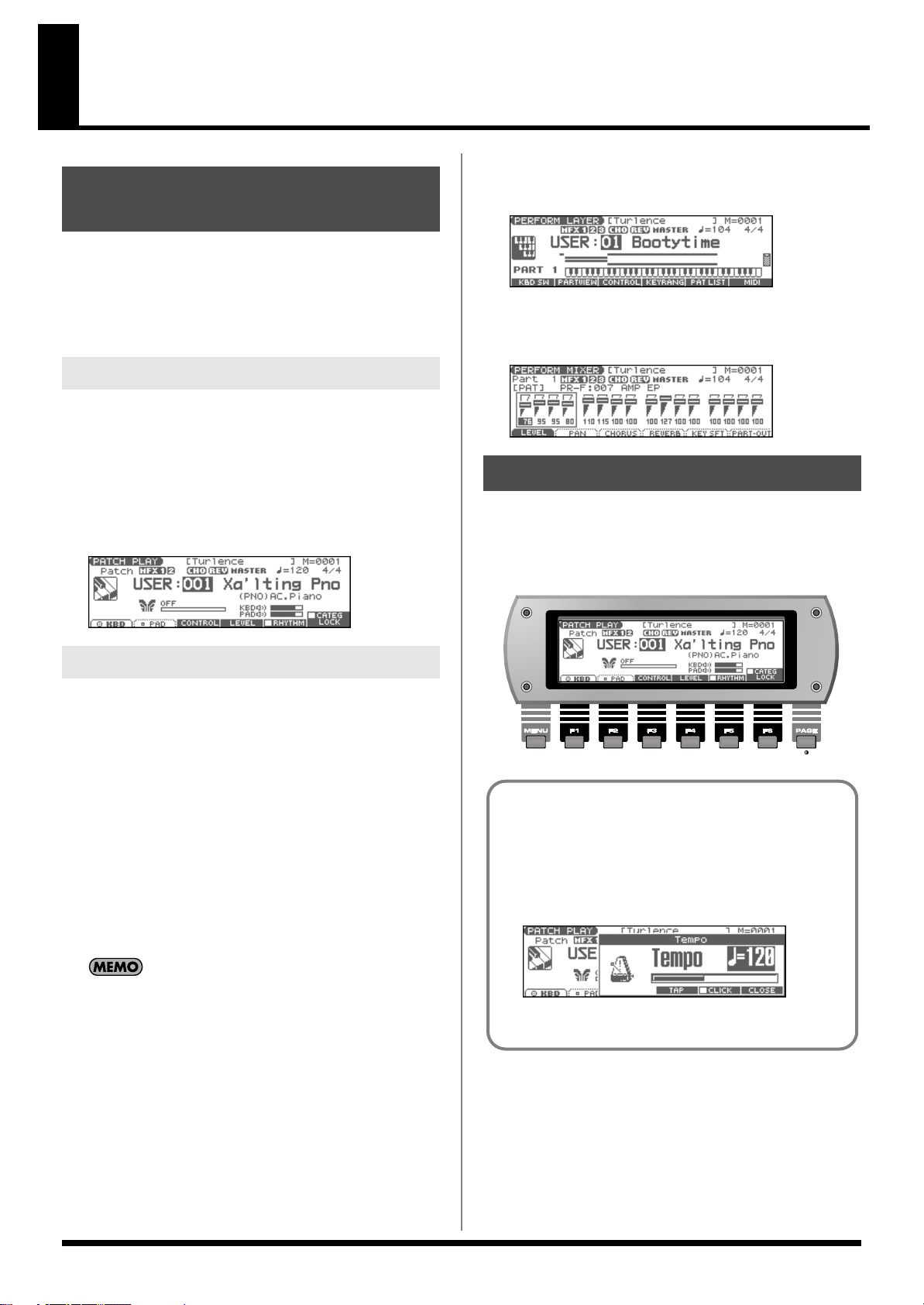
Basic Operation of the Fantom-Xa
To select the LAYER screen
Switching the Sound Generator Mode
The Fantom-Xa has two sound generating modes: Patch mode,
Performance mode. You can select the sound generating mode
(state) that is most appropriate for how you are playing the Fantom-
Xa.
Use the following procedure to switch between these modes.
Patch Mode
In this mode you can use the keyboard and pads to play individual
sounds (patches/rhythm sets).
The keyboard and pads each have their own sound generator and
part, and are connected on a single MIDI channel.
To select Patch mode
1.
Press [PATCH/RHYTHM].
fig.PatchPlay
1.
Press [LAYER/SPLIT].
fig.PfmLayer
To select the MIXER screen
1.
Press [MIXER].
fig.PfmMixer
About the Function Buttons
The six [F1]–[F6] buttons (function buttons) located below the
display execute various functions, and their operation will differ
depending on the screen. Functions will be listed in the bottom of the
screen.
fig.FButtons
Performance Mode
This mode allows you to combine multiple sounds (patches or
rhythm sets).
LAYER/SPLIT screen
Use this screen when you want to play two or more sounds
(patches/rhythm sets) together.
You can play patches together (Layer) or divide the keyboard into
two regions and play different patches in each region (Split).
MIXER screen
Use this screen when you want to mix the sounds by adjusting the
level and pan for each of the 16 parts.
The LAYER screen and MIXER screen provide different views
of the same performance. For example, you’ll want to use the
LAYER/SPLIT screen when you’re setting up a keyboard split,
or use the MIXER screen when you’re adjusting the effect
settings or volume balance of the patches for each part.
Window
The somewhat smaller screens that appear temporarily on top
of the normal screens are called windows. Various types of
windows appears according to the situation. Some display lists,
others allow you to make settings, and still others ask you to
confirm an operation.
fig.Tempo
Press [EXIT] to close the window. Some windows will close
automatically when an operation is performed.
26
Page 27
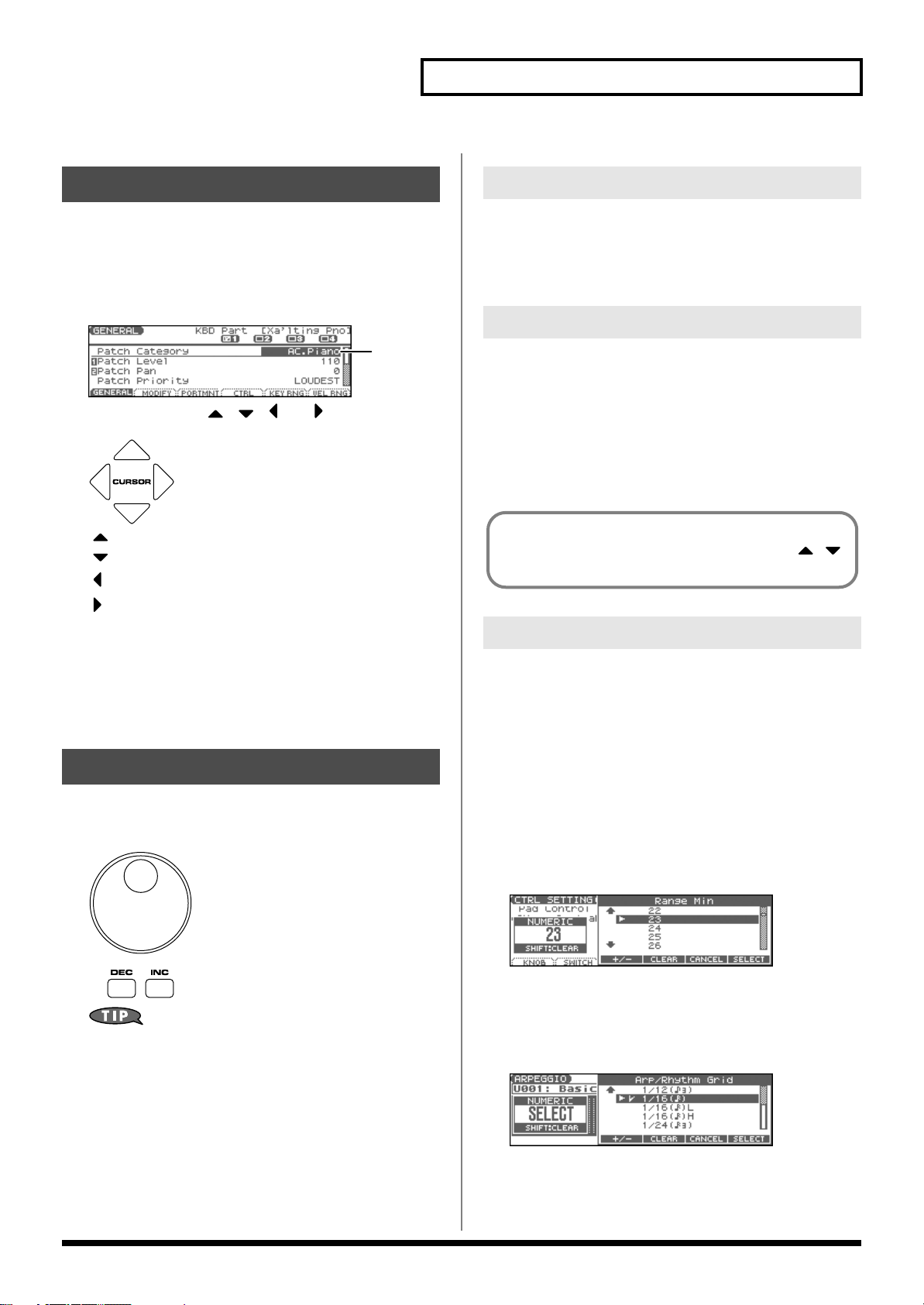
Basic Operation of the Fantom-Xa
Moving the Cursor
A single screen or window displays multiple parameters or items for
selection. To edit the setting of a parameter, move the cursor to the
value of that parameter. To select an item, move the cursor to that
item. When selected with the cursor, a parameter value or other
selection is highlighted.
fig.CursorScreen
Cursor
Move the cursor with the , , and (cursor buttons).
fig.CURSOR
: moves the cursor up.
: moves the cursor down.
: moves the cursor to the left.
: moves the cursor to the right.
• If you hold down one cursor button while you also press the
cursor button for the opposite direction, the cursor will move
more rapidly in the direction of the first-pressed cursor button.
• When the cursor is displayed, pressing [ENTER] will sometimes
display a list of the available choices for that parameter. This is
convenient when you want to see what your choices are.
Changing a Value
VALUE Dial
Turning the VALUE dial clockwise increases the value,
counterclockwise decreases the value.
• Holding down [SHIFT] as you move the VALUE dial increases
value increments so you can make large value changes faster.
[INC] and [DEC]
Pressing [INC] increases the value, and [DEC] decreases it.
• Keep the button pressed for continuous adjustment.
• For faster value increases, keep [INC] pressed down and press
[DEC]. For decreasing value faster, keep [DEC] pressed down
and press [INC].
• If you press [INC] or [DEC] while holding down [SHIFT], the
value increments will get bigger.
When the cursor is located at a parameter value, press [ENTER]
to display a window where you can set the value. Use
to select a value, and then press [ENTER] to finalize the setting.
Using the pads
In some cases when the cursor is located at an input location, you
can press [ENTER] to see a list of parameter values. For some of
these lists, you can use the pads to input or specify the value.
1.
Press [TRIGGER] and [CATEGORY] simultaneously so both
buttons are lit.
You can use the pads to input or specify the value.
To change the value, use the VALUE dial or the [INC] [DEC]
buttons.
fig.VALUE
In each screen of the Fantom-Xa, you can use the cursor buttons
to move the area displayed as highlighted, and modify its value.
* Each parameter has its own range of possible values, so you cannot set
any value smaller than the minimum value or greater than the
maximum value.
When inputting a numerical value
PAD [0]–[9]:
[SHIFT]:
fig.PadNumber
Input numerals 0–9
Cancels the numeral you input
When inputting directly
Pressing a pad will directly input the corresponding value.
From the top, the items in the list correspond to pads [0]–[9].
fig.PadDirect
27
Page 28
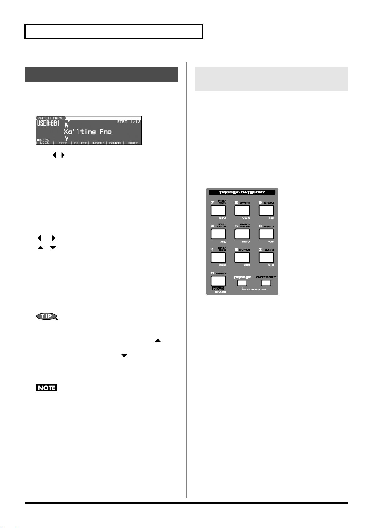
Basic Operation of the Fantom-Xa
Assigning a Name
On the Fantom-Xa, you can assign names to each patch, rhythm set,
performance, Song, Sample, and Pattern. The procedure is the same
for any type of data.
fig.PatchName
1.
Press to move the cursor to the location where you
wish to input a character.
Turn the VALUE dial, or press [INC] [DEC] to specify the
2.
character.
• [F2 (TYPE)]: Selects the type of character. Each time you
press this, you will alternately select the first
character of a character set: uppercase (A),
lowercase (a), or numerals and symbols (0).
• [F3 (DELETE)]: Deletes the character at the cursor location.
• [F4 (INSERT)]: Inserts a space at the cursor location.
• or : Move the cursor.
•, :Switch between uppercase and lowercase
letters.
Using the Pads to Specify Characters
You can use the pads to specify characters.
By pressing a pad one or more times, you can successively select the
letters, numerals, and symbols that appear on the pad. For example,
if you repeatedly press pad 1, you will cycle through the available
choices like this: 1 → A → B → C → 1 → A...
• You can switch between uppercase and lowercase letters for the
character to be entered by pressing [F1 (CAPS LOCK)] to add a
check mark (✔).
• Press PAD [0] (SPACE) to replace the character at the cursor
location with a space.
fig.PAD
* If you decide to discard your input, press [F5 (CANCEL)].
Available Characters/Symbols
space, A–Z, a–z, 0–9, ! “ # $ % & ` ( ) * + , - . / : ; < = > ? @ [ \ ] ^
_ ` { | }
From a naming screen you can press [MENU] and select “1.
Undo” to return the name to what it was before you changed it.
From [MENU] you can select “2. To Upper” or press to
change the character at the cursor to uppercase. From [MENU]
you can select “3. To Lower” or press to change the
character at the cursor to lowercase. From [MENU] you can
select “4. Delete All” to clear all the characters you were
inputting.
Song file names may not contain lowercase characters or certain
symbols (“ * + , . / : ; < = > ? [ \ ] |).
28
Page 29
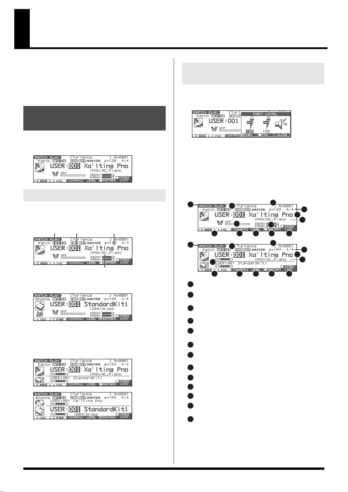
Playing in Patch Mode
Patch group Patch number
Patch category
Patch name
1
4
1
4
6
6
Displays the Control Setting screen.
Adjusts the volume of the keyboard part and pad part.
1
8
2
3
4
12
6
5
13
7
11
10
3
3
Switches the keyboard part and pad part.
9
2
2
5
8
11 12 13109
11 12 13109
5
7
Indicates the current sound generating mode.
Indicates the volume of the Keyboard part and Pad part.
Indicates multi-effects (MFX1, 2), chorus (CHO),
reverb (REV), and masterring (MASTER) on and off.
Indicates the name of the currently selected song,
the measure location.
Indicates the time signature, and the tempo.
Determines whether you will be selecting
patches or rhythm sets.
Indicates/selects the patch category.
Selects whether the patch category will be locked.
Indicates/selects the group, number,
and name of the selected patch.
This indicates the function that is assigned to the D Beam,
and the response status of the D Beam.
8
In Patch mode, the keyboard and the pads are each used to play a
single sound (patch/rhythm set).
The keyboard controller section and the pad controller section each
have their own sound generator part, and each are connected by
their own MIDI channel. This means you can play separate sounds
on the keyboard and the pads.
About the PATCH PLAY Screen
Press [PATCH/RHYTHM]. You will enter Patch mode, and the
PATCH PLAY screen appears.
fig.PatchPlay
Keyboard Part and Pad Part
Adjust the Volume of the Keyboard Part and Pad Part
1.
In the PATCH PLAY screen, press [F4 (LEVEL)].
The PART LEVEL window appears.
fig.PartLevel
2.
Press [F4 (KBD)] or [F5 (PAD)] to select the part.
Use the VALUE dial or [INC] [DEC] to adjust the volume.
3.
Press [F6 (CLOSE)] to close the window.
4.
Functions in the PATCH PLAY screen
fig.PatchFunc.e
The Fantom-Xa has two parts; a Keyboard part and a Pad part.
• Press [F1 (KBD)] to select the Keyboard part.
fig.KbdPart
• Press [F2 (PAD)] to select the Pad part.
fig.PadPart
• Press [PAGE] to switch the PATCH PLAY screen.
This screen simultaneously displays the settings of the
Keyboard part and the Pad part.
fig.DualPart
fig.DualPart2
29
Page 30
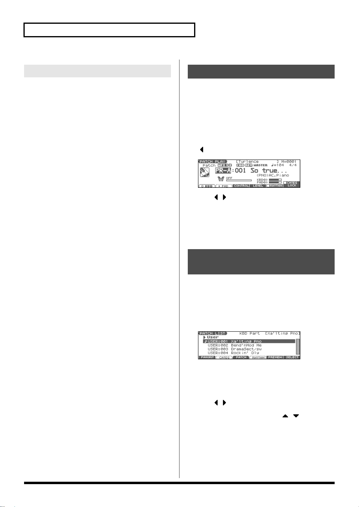
Playing in Patch Mode
Patch/Rhythm Set Group
The Fantom-Xa has several patch groups, including the User group
and Preset groups A–F and GM, with each group storing 128 patches
(256 in GM, USER). What’s more, you can further expand your
options by installing an optional Wave Expansion Board (SRX series;
sold separately), enabling you to select from a huge assortment of
available patches.
USER
This is the group inside the Fantom-Xa which can be rewritten.
Patches you yourself create can be stored in this group. The Fantom-
Xa includes 256 preset patches and 32 rhythm sets.
PR-A–F (Preset A–F), PRST (Preset)
This is the group inside the Fantom-Xa which cannot be rewritten.
However you may modify the settings of the currently selected
patch, and then store the modified patch in User memory. Groups
A–F already contain 128 prepared patches each, for a total of 768
patches.
GM (General MIDI 2)
This is an internal group of patches compatible with General MIDI 2,
a system of MIDI function specifications designed to transcend
differences between makers and types of devices; these patches
cannot be overwritten. Furthermore, settings of currently selected
patches from this group cannot be changed. The Fantom-Xa includes
256 preset patches.
Selecting a Patch
Press [PATCH/RHYTHM] to access the PATCH PLAY
1.
screen.
2.
Press [F1 (KBD)] or [F2 (PAD)] to select the Keyboard part
or Pad part.
* To select a rhythm set, press [F5 (RHYTHM)] to add a check mark
(✔).
3.
If you select a patch group (or a rhythm set group), press
and use the VALUE dial or [INC] [DEC] to select.
fig.PatchGroup
Press to move the cursor to the patch number.
4.
5.
Use the VALUE dial or [INC] [DEC] to select a patch (or a
rhythm set).
If you selected a patch (or a rhythm set) for the keyboard part,
play the keyboard to hear the sound. If you selected a patch (or
a rhythm set) for the pad part, play the pads to hear the sound.
Selecting Patches from the List
CARD (Memory Card)
This group lets you use patches stored on a memory card inserted in
the rear panel card slot. Since the data in this group can be rewritten,
you can use this group to store patches that you create.
EXP (Wave Expansion Board installed in EXP
Slot)
These are groups used when using patches from Wave Expansion
Board installed in the EXP slot, and cannot be rewritten. However
you may modify the settings of the currently selected patch, and
then store the modified patch in User memory and Memory card.
The number of onboard patches depends on the specific Wave
Expansion Board installed.
* EXP patches can be selected only if a Wave Expansion Board (SRX
series; sold separately) is installed in the slot.
You can display a list of patches and select a patch from that list.
Press [PATCH/RHYTHM] to access the PATCH PLAY
1.
screen.
Press [ENTER].
2.
The PATCH LIST screen appears.
fig.PatchList
To select a patch, press [F3 (PATCH)].
3.
To select a rhythm set, press [F4 (RHYTHM)].
If you press [F4 (RHYTHM)], the RHYTHM LIST screen
appears.
4.
Press to select a group.
Use the VALUE dial, [INC] [DEC], or to select a
5.
patch/rhythm set.
Press [ENTER] to confirm your selection.
6.
30
Page 31

Playing in Patch Mode
Using the PATCH SELECT Screen
1.
Press [PATCH/RHYTHM] to access the PATCH PLAY
screen.
Press [PATCH SELECT].
2.
The PATCH SELECT screen appears.
fig.PatchSelect
3.
To select a rhythm set, press [F5 (RHYTHM)] to add a check
mark (✔).
If you add a mark, the RHYTHM SELECT screen appears.
4.
Press [F1] or [F2] to select a group.
5.
Use [F3], [F4], PART/TRACK [1]–[8], [INC] [DEC], ,
or the VALUE dial to select a patch/rhythm set.
Press [ENTER] to return to the PATCH PLAY screen.
6.
Auditioning Patches/Rhythm Sets (Phrase Preview)
Selecting Favorite Patches/ Rhythm Sets (Favorite Patch)
In the patch mode, you can bring together your favorite and most
frequently used patches (or rhythm sets) in one place by registering
them in the favorite patch. By using this function, you can rapidly
select favorite patches from Preset/User/Card area or a Wave
Expansion Board. You can register a total of 64 sounds (8 sounds x 8
banks) as favorite patches.
Registering a Favorite Patch/ Rhythm Set
1.
In the PATCH PLAY screen, select the patch (or rhythm set)
that you wish to register.
2.
Press [ENTER].
The PATCH LIST screen appears.
3.
Press [F1 (FAVORIT)].
The FAVORITE PATCH screen appears.
fig.Favorite
The Fantom-Xa allows you to preview patches by hearing a phrase
appropriate for each type of patch.
1.
Press [PATCH/RHYTHM] to access the PATCH PLAY
screen.
Press [ENTER] to access the PATCH LIST screen.
2.
3.
Press and hold [F5 (PREVIEW)].
The patch selected in the PATCH LIST screen will be sounded.
Release your finger from [F5 (PREVIEW)], and the phrase
4.
will stop playing.
* If you wish to change how the phrase is played by Phrase Preview, you
can edit the Preview Mode parameter (p. 194).
Use the VALUE dial or to select the Bank.
4.
5.
Press PART/TRACK [1]–[8], [INC] [DEC], or to
select a favorite number.
6.
Press [F3 (REGIST)] to execute the registration.
Press [F1 (LIST)] to return to the PATCH LIST screen.
7.
Canceling a patch registration
By pressing [F2 (REMOVE)] you can cancel the patch (or rhythm set)
registration that is selected in the FAVORITE PATCH screen.
Choosing the Favorite Patch/ Rhythm Set
1.
Press [PATCH/RHYTHM] to access the PATCH PLAY
screen.
2.
Press [ENTER] to access the PATCH LIST screen.
3.
Press [F1 (FAVORIT)].
The FAVORITE PATCH screen appears.
4.
To change the Bank, use the VALUE dial or .
5.
Press PART/TRACK [1]–[8], [INC] [DEC], or to
select the patch.
6.
Press [F6 (SELECT)] or [ENTER] to confirm your selection.
31
Page 32

Playing in Patch Mode
Selecting Patches by Category
The Fantom-Xa allows you to specify a type (category) of patch so
that you can quickly find the desired patch. There are a total of 38
categories.
1.
Press [PATCH/RHYTHM] to access the PATCH PLAY
screen.
2.
Press [F1 (KBD)] or [F2 (PAD)] to select the Keyboard part
or Pad part.
* If a check mark (✔) is displayed above [F5 (RHYTHM)], press [F5
(RHYTHM)] to remove the mark.
Press to move the cursor to the “Patch Category,” and
3.
use the VALUE dial or [INC] [DEC] to select the desired
category.
4.
Press [F6 (CATEG LOCK)] to add a check mark (✔).
fig.PatchCategory
5.
Use [CURSOR] to move the cursor to the patch group or
patch number, and use the VALUE dial or [INC] [DEC] to
select the patch.
Selecting from the List
Press [PATCH/RHYTHM] to access the PATCH PLAY
1.
screen.
2.
Press [ENTER].
The PATCH LIST screen appears.
Press [F2 (CATEG)].
3.
The CATEGORY screen appears.
fig.CategoryList
The following categories can be selected.
Category
- - PNO AC.Piano Acoustic Piano PIANO
EP EL.Piano Electric Piano
KEY Keyboards Other Keyboards (Clav,
BEL Bell Bell, Bell Pad
MLT Mallet Mallet
ORG Organ Electric and Church Organ
ACD Accordion Accordion
HRM Harmonica Harmonica, Blues Harp
AGT AC.Guitar Acoustic Guitar GUITAR
EGT EL.Guitar Electric Guitar
DGT Dist.Guitar Distortion Guitar
BS Bass Acoustic & Electric Bass BASS
SBS Synth Bass Synth Bass
STR Strings Strings STR/
ORC Orchestra Orchestra Ensemble
HIT Hit&Stab Orchestra Hit, Hit
WND Wind Winds (Oboe, Clarinet etc.) WIND/
FLT Flute Flute, Piccolo
BRS AC.Brass Acoustic Brass
SBR Synth Brass Synth Brass
SAX Sax Sax
PLK Plucked Plucked (Harp etc.) WORLD
ETH Ethnic Other Ethnic
FRT Fretted Fretted Inst (Mandolin etc.)
BPD Bright Pad Bright Pad Synth PAD/
SPD Soft Pad Soft Pad Synth
VOX Vox Vox, Choir
HLD Hard Lead Hard Synth Lead SYNTH
SLD Soft Lead Soft Synth Lead
TEK Techno Synth Techno Synth
PLS Pulsating Pulsating Synth
FX Synth FX Synth FX (Noise etc.)
SYN Other Synth Poly Synth
PRC Percussion Percussion DRUM
SFX Sound FX Sound FX
BTS Beat&Groove Beat and Groove
DRM Drums Drum Set
CMB Combination Other patches which use
No Assign No assign —
Contents Group
[PAD]
[0]
ORG/
Harpsichord etc.)
Split and Layer
KBD
[1]
[2]
[3]
ORCH
[4]
BRASS
[5]
[6]
VOX
[7]
[8]
[9]
4.
Use PAD [0]–[9] to select the category group.
Press to select the desired category.
5.
6.
Use the VALUE dial, [INC] [DEC], or to select a
patch.
7.
Press [F6 (SELECT)] or [ENTER] to confirm your selection.
From the PATCH PLAY screen, you can access the CATEGORY
screen by pressing [CATEGORY].
32
Page 33

Playing in Patch Mode
Transposing the Keyboard in Octave Units (Octave Shift)
The Octave Shift function transposes the pitch of the keyboard in 1
octave units (-3– +3 octaves).
For playing a bass part more easily using your right hand, transpose
the keyboard down by 1 or 2 octaves.
* Octave Shift applies only to the keyboard part.
In the PATCH PLAY screen, press OCTAVE [-] or [+] to set
1.
the amount of transposition (-3– +3).
The button will light if this is set.
• Each time you press OCTAVE [+], the amount of transposition
will change in the order of +1, +2, and +3. Each time you press
OCTAVE [-], the amount of transposition will change in the
order of -1, -2, and -3.
• If you press both buttons simultaneously, the amount of
movement will be zero.
fig.OctaveShift
Transposing the Keyboard in Semitone Steps (Transpose)
Transpose changes keyboard pitch in units of semitones.
This function is useful when you play transposed instruments such
as trumpet or clarinet following a printed score.
* Transpose applies only to the keyboard part.
1.
In the PATCH PLAY screen, hold down [SHIFT] and press
OCTAVE [-] or [+] to adjust the Transpose setting (G–F#: -5–
+6 semitones).
• If you hold down [SHIFT] and press both buttons
simultaneously, the amount of movement will be zero.
fig.Transpose
There is a single Transpose setting (Setup parameter) for the
entire Fantom-Xa. The changed setting will be remembered
even if you switch patches or performances.
There is a single Octave Shift setting (Setup parameter) for the
entire Fantom-Xa. The changed setting will be remembered
even if you switch patches or performances.
Selecting the Tones That Will Sound (Tone On/Off)
Since a patch is a combination of up to four tones, you can switch
unwanted (tones out of the four) off and get just the sound of a
specific tone.
• In the PATCH PLAY screen, press TONE SW [1]–[4] (PART/
TRACK [1]–[4]) to turn each tone on/off.
* If you want just one or two tones to sound in a patch, turn the others
off and store that setting on a patch. This cuts nonessential use of the
Fantom-Xa’s simultaneous voices.
33
Page 34

Playing in Patch Mode
Playing Single Notes (Monophonic)
When using a patch for a naturally monophonic instrument such as
sax or flute, it is effective to play in mono.
1.
From the PATCH PLAY screen, press [PATCH EDIT].
2.
Press [F1 (COMMON)] and then press [F4 (CTRL)].
Press to move the cursor to “Mono/Poly.”
3.
Use the VALUE dial or [INC] [DEC] to select “MONO.”
4.
Now you can play in mono mode.
If you assign “Mono/Poly” as a function to be controlled by the
assignable switches ([ ]/[ ]), you can easily switch
between mono/poly by pressing a button (p. 84).
Creating Smooth Pitch Changes (Portamento)
Portamento is an effect which smoothly changes the pitch from the
first-played key to the next-played key. By applying portamento
when Mono mode is selected (see the preceding item), you can
simulate performance effects such as slurring on a violin.
From the PATCH PLAY screen, press [PATCH EDIT].
1.
2.
Press [F1 (COMMON)] and press [F3 (PORTMNT)].
Press to move the cursor to “Portamento Switch.”
3.
Use the VALUE dial or [INC] [DEC] to select “ON.”
4.
You’re ready to play portamento.
Selecting the Parameter
Controlled by the Realtime
Controllers or D Beam
Controller (Control Setting)
The Fantom-Xa lets you assign the parameters that will be affected
when you operate the realtime control knobs, assignable switches, D
Beam, pitch bend, or modulation lever. This lets you modify the
sound in a variety of ways by operating the controllers.
Specifying the Part that Will be Affected by the Controller
You can specify whether operating the controller will affect the
sound assigned to the keyboard part or the sound assigned to the
pad part.
1.
From the PATCH PLAY screen, press [F3 (CONTROL)] and
press [F3 (PART)].
The CONTROL SETTING screen appears.
fig.ControlPart
2.
Press to select the parameter.
3.
Use the VALUE dial or [INC] [DEC] to select the part.
4.
If you want to keep the settings, press [F6 (WRITE)].
* When Patch mode is selected, controller settings cannot be saved for
each individual patch. Controller settings are saved as system settings.
5.
Press [EXIT] to return to the PATCH PLAY screen.
If you assign “Portamento Switch” as a function to be controlled
by the assignable switches ([ ]/[ ]), you can use a button
to easily turn portamento on/off (p. 84).
Playing Percussion Instruments
In Patch mode, you can play percussion instruments from the
keyboard and pad by selecting a rhythm set. As the rhythm tone
assigned to each key and pad varies by the rhythm set selected, you
can play a wide range of percussion instruments.
34
Parameter
Bender and Modulation Part Select
D Beam Part Select Part controlled by the D Beam
Knob Part Select Part controlled by the realtime
For details on assigning a parameter to a controller, refer to
Modifying the Sound in Real Time
Value Explanation
KBD,
PAD
Part controlled by pitch bend messages or modulation messages
control knobs
(p. 80).
Page 35

Creating a Patch
Four Tips for Editing Patches
Select a patch that is similar to the sound you wish to
create
With the Fantom-Xa, you have total control over a wide variety of
settings. Each item that can be set is known as a
you change the values of parameters, you are doing what is referred
to as
Editing
. This chapter explains the procedures used in creating
patches, and the functions of the patch parameters.
(p. 30)
It’s hard to create a new sound that’s exactly what you
want if you just select a patch and modify its parameters at
random. It makes sense to start with a patch whose sound
is related to what you have in mind.
Decide which tones will sound (p. 33)
Since a patch is a combination of up to any four tones, you
should listen to how the individual tones sound before you
edit. Then decide which tones you are going to use. It is
important to turn off unused tones to avoid wasting voices,
unnecessarily reducing the number of simultaneous notes
you can play.
Check the Structure setting (p. 38)
The important Structure parameter determines how the
four tones combine. Before you select new tones, make
sure you understand how the currently selected tones are
affecting each other.
Turn Effects off (p. 157)
Since you will hear the original sound of the patch itself
when the effects are turned off, the results of your
modifications will be easier to hear. Actually, sometimes
just changing effects settings can give you the sound you
want.
How to Make Patch Settings
1.
Press [PATCH/RHYTHM] to access the PATCH PLAY
screen.
parameter
. When
Press [F1]–[F6], and then press to select the
5.
parameter.
Some parameters can be set independently for each tone.
To select the tone you want to edit, press TONE SELECT [1]–[4]
(PART/TRACK [5]–[8]) or .
fig.WavePitch
6.
Use the VALUE dial or [INC] [DEC] to change the value.
7.
Repeat steps 4–6 to set each parameter.
8.
Press [WRITE] to save the changes you’ve made (p. 37).
If you do not wish to save changes, press [EXIT] to return to
the PATCH PLAY screen.
If you return to the PATCH PLAY screen without saving, an “*”
will be displayed at the left of the patch group.
If you turn off the power or select a different sound while the
display indicates “*,” your edited patch will be lost.
Editing in a Graphic Display (Zoom Edit)
You can edit while viewing a graphic display of the most frequently
used important parameters. Zoom Edit lets you edit the following
parameters.
Parameter
Pitch Envelope
TVF p. 45 LFO 1/2 p. 52
TVF Envelope p. 46 Step LFO p. 54
With the screen for editing the above parameters shown,
1.
press [F6 (ZOOM)].
The Zoom Edit screen will appear.
fig.ZoomEdit
page Parameter page
p. 44 TVA Envelope p. 48
Select the part (keyboard or pad) and patch whose settings
2.
you want to edit (p. 30).
* You cannot edit the patches in the GM2 group.
3.
Press [PATCH EDIT] to access the PATCH EDIT screen.
fig.PatchEdit
* Set the Structure Type (p. 38) and Booster Gain (p. 39) parameters in
this screen.
4.
Press [F1 (COMMON)]–[F6 (LFO&OUT)] to select the
parameter group.
2.
Press [F1]–[F5] to select the parameter group.
Press [CURSOR] to select the parameter.
3.
Use the VALUE dial or [INC] [DEC] to change the value.
4.
You can use the REALTIME CONTROL knobs to set the value.
5.
When you have finished editing, press [F6 (EXIT)].
35
Page 36

Creating a Patch
Using the REALTIME CONTROL Knobs to Change the Value
If a number is displayed for the parameter name ( , , ,
), you can use the REALTIME CONTROL knobs (C1–C4) to set
4
the value.
If you press the button located at the right of the REALTIME
CONTROL knobs to make the indicator light, the knobs will control
their original functions.
fig.06-010
1 2 3 4
You can use the same knobs to edit the values in the Zoom Edit
screen (p. 35) as well.
1
2 3
Initializing Patch Settings
“Initialize” means to return the settings of the currently selected
sound to a standard set of values.
* The Initialize operation will affect only the currently selected sound;
the sounds that are stored in user memory will not be affected. If you
wish to restore all of the Fantom-Xa’s settings to their factory values,
perform a Factory Reset (p. 203).
1.
Press [PATCH/RHYTHM] to access the PATCH PLAY
screen.
2.
Select the part (keyboard or pad) and patch that you want to
initialize (p. 30).
3.
Press [PATCH EDIT] to access the PATCH EDIT screen.
4.
Hold down [SHIFT] and press [F5 (INIT)].
A message will ask you for confirmation.
5.
Press [F6 (EXEC)].
The initialization will be carried out.
* To cancel, press [F5 (CANCEL)].
Copying Patch (Tone) Settings
This operation copies the settings of any desired patch to the
currently selected patch.
Press [PATCH/RHYTHM] to access the PATCH PLAY
1.
screen.
2.
Select the part (keyboard or pad) and the copy-destination
patch (p. 30).
Press [PATCH EDIT] to access the PATCH EDIT screen.
3.
4.
Hold down [SHIFT] and press [F6 (TONE CPY)].
The Patch Tone Copy window appears.
fig.ToneCopy
5.
Press [CURSOR] to move the cursor, and use the VALUE
dial or [INC] [DEC] to select the “Source (copy-source)”
group and number, and the tone.
* By pressing [F4 (COMPR)] to add a check mark (✔), you can check
the copy-source patch (Compare function).
Press [CURSOR] to move the cursor, and select the
6.
“Destination (copy-destination)” tone.
7.
Press [F6 (EXEC)].
A message will ask you for confirmation.
8.
Press [F6 (EXEC)] to execute the copy operation.
* To cancel, press [F5 (CANCEL)].
The Compare Function
For the Patch Tone Copy and Patch Save operations, you can
use the Compare function.
If you want to play the copy-source or write-destination patch,
press [F4 (COMPR)] to add a check mark (✔). Now you can
play the copy-source or write-destination patch from the
keyboard or pads.
* The patch auditioned using the Compare function may sound
slightly different than when it is played normally.
36
Page 37

Changes you make to sound settings are temporary, and will be lost
if you turn off the power or select another sound. If you want to keep
the modified sound, you must save it in the internal USER group
(user memory) or CARD group (memory card).
When you edit the patch settings, an “*” will appear in the PATCH
PLAY screen.
When you perform the save procedure, the data that previously
occupied the save destination will be lost.
1.
Make sure that the patch you wish to save is selected.
2.
Press [WRITE].
The WRITE MENU screen appears.
fig.PatchWrite
Creating a Patch
One-shot Waveform and Loop
Waveform
The internal waveforms of the Fantom-Xa fall into the following two
groups.
One-shot:
These waveforms contain sounds that have short decays. A one-shot
waveform records the initial rise and fall of the sound.
The Fantom-Xa also contains many other one-shot waveforms that
are elements of other sounds. These include attack components such
as piano-hammer sounds and guitar fret noises.
* It is not possible to use the envelope to modify a one-shot waveform to
create a decay that is longer than the original waveform, or to turn it
into a sustaining sound.
Loop:
These waveforms include sounds with long decays as well as
sustained sounds. Loop waveforms repeatedly play back (loop) the
portion of the waveform after the sound has reached a relatively
steady state.
The Fantom-Xa’s looped waveforms also include components of
other sounds, such as piano-string resonant vibrations and the
hollow sounds of brass instruments.
3.
Press [F2 (PAT/RHY)].
* Alternatively, you can use or to select “Patch/Rhythm,”
and then press [ENTER].
The PATCH NAME screen appears.
fig.PatchName
4.
Assign a name to the patch.
For details on assigning names, refer to p. 28.
5.
When you have finished inputting the name, press [F6
(WRITE)].
A screen will appear, allowing you to select the write-
destination patch.
6.
Use the VALUE dial, [INC] [DEC], or and [F1
(USER)] [F2 (CARD)] to select the write destination and
patch number.
* By pressing [F4 (COMPR)] to add a check mark (✔), you can check
the write-destination patch (Compare function).
The following diagram shows an example of sound (electric organ)
that combines one-shot and looped waveforms.
fig.06-005.e
Tips for Using an Acoustic
Instrument’s Waveform
With many acoustic instruments such as piano and sax, extreme
timbral changes occur during the first few moments of each note.
7.
Press [F6 (WRITE)].
A message will ask you for confirmation.
Press [F6 (EXEC)] to execute the save operation.
8.
* To cancel, press [F5 (CANCEL)].
Never switch off the Fantom-Xa while data is being saved.
37
Page 38

Creating a Patch
Functions of Patch Parameters
Changing How a Tone Is Sounded (Structure)
Parameter
Struct 1 & 2, 3 & 4
Value Explanation
TYPE 01–TYPE 10 Determines how tone 1 and 2, or tone 3 and 4 are connected.
(Structure Type)
TYPE 1
TONE 1 (3)
TONE 2 (4)
WG
WG
TVATVF
TVF TVA
With this type, tones 1 and 2 (or 3 and 4) are independent. Use this type
when you want to preserve PCM sounds or create and combine
sounds for each tone.
TYPE 3
TONE 1 (3)
TONE 2 (4)
WG
WG
TVA TVF
B
TVF TVA
This type mixes the sound of tone 1 (3) and tone 2 (4), applies a filter,
and then applies a booster to distort the waveform.
TYPE 5
TONE 1 (3)
TONE 2 (4)
WG
TVA TVF
WG
R
TVF TVA
The following 10 different Types of combination are available.
TYPE 2
TONE 1 (3)
TONE 2 (4)
WG
WG
TVA
TVF
TVF TVA
This type stacks the two filters together to intensify the characteristics
of the filters. The TVA for tone 1 (or 3) controls the volume balance between the two tones.
TYPE 4
TONE 1 (3)
TONE 2 (4)
WG
TVA TVF
WG
B
TVF TVA
This type applies a booster to distort the waveform, and then combines
the two filters. The TVA for tone 1 (or 3) controls the volume balance
between the two tones and adjusts booster level.
TYPE 6
TONE 1 (3)
TONE 2 (4)
WG
TVA TVF
WG
R
TVF TVA
This type uses a ring modulator to create new overtones, and combines the two filters. The tone 1 (3) TVA will control the volume balance of the two tones, adjusting the depth of ring modulator.
This type uses a ring modulator to create new overtones, and in addition mixes in the sound of tone 2 (4) and stacks the two filters. Since
the ring-modulated sound can be mixed with tone 2 (4), tone 1 (3) TVA
can adjust the amount of the ring-modulated sound.
TYPE 7
TONE 1 (3)
TONE 2 (4)
WG
WG
TVATVF
R
TVF TVA
This type applies a filter to tone 1 (3) and ring-modulates it with tone
2 (4) to create new overtones.
TYPE 8
TONE 1 (3)
TONE 2 (4)
WG
WG
TVATVF
R
TVF TVA
This type sends the filtered tone 1 (3) and tone 2 (4) through a ring
modulator, and then mixes in the sound of tone 2 (4) and applies a filter to the result.
TYPE 9
TONE 1 (3)
TONE 2 (4)
WG
WG
TVATVF
TVF TVA
R
This type passes the filtered sound of each tone through a ring modulator to create new overtones. The tone 1 (3) TVA will control the volume balance of the two tones, adjusting the depth of ring modulator.
TYPE 10
TONE 1 (3)
TONE 2 (4)
WG
WG
TVATVF
TVF TVA
R
This type passes the filtered sound of each tone through a ring modulator to create new overtones, and also mixes in the sound of tone 2 (4).
Since the ring-modulated sound can be mixed with tone 2 (4), tone 1
(3) TVA can adjust the amount of the ring-modulated sound.
* When TYPE 2–10 is selected and one tone of a pair is turned off, the other tone will be sounded as TYPE 1 regardless of the displayed setting.
38
Page 39

Creating a Patch
Booster
fig.Boost1.e
The Booster is used to distort the incoming signal.
Booster level
TVA
WG1
WG2
Booster
Adds to WG1
Shift in waveform by WG1
Distorted area of the
Waveform changes
WG2
Uses WG1 as LFO
Adjusts WG1 output
* If you limit the keyboard area in which a tone will sound (Keyboard Range, p. 42) or limit the range of velocities for which it will sound (Velocity Range, p.
42), the result in areas or ranges where the tone does not sound is just as if the tone had been turned off. This means that if TYPE 2–10 is selected and you
create a keyboard area or velocity range in which one tone of a pair does not sound, notes played in that area or range will be sounded by the other tone as
TYPE 1 regardless of the displayed setting.
Parameter
Booster 1&2, 3&4
(Booster Gain)
fig.Boost2.e
In addition to using this to create distortion, you can use the waveform
(WG1) of one of the tones as an LFO which shifts the other waveform
(WG2) upward or downward to create modulation similar to PWM (pulse
width modulation). This parameter works best when you use it in
conjunction with the Wave Gain parameter (p. 43).
Value Explanation
0, +6, +12, +18 When a Structure Type of TYPE 3 or TYPE 4 is selected, you can adjust the depth of the booster.
The booster increases the input signal in order to distort the sound. This creates the distortion effect
frequently used with electric guitars. Higher settings will produce more distortion.
Ring Modulator
fig.RingMod
A ring modulator multiplies the waveforms of two tones with each other,
generating many new overtones (in harmonic partials) which were not
present in either waveform. (Unless one of the waveforms is a sine wave,
evenly-spaced frequency components will not usually be generated.)
As the pitch difference between the two waveforms changes the harmonic
structure, the result will be an unpitched metallic sound. This function is
suitable for creating metallic sounds such as bells.
39
Page 40

Creating a Patch
Parameter Group [F1 (COMMON)] Settings Common to the Entire Patch
[F1 (GENERAL)]
Parameter marked with a “★” can be controlled using specified MIDI messages
(Matrix Control, p. 49)
Parameter
Patch Category
Patch Level 0–127 Volume of the patch
Patch Pan L64–0–63R Left/right position of the patch
Patch Priority LAST, LOUDEST How notes will be managed when the maximum polyphony is exceeded (128 voices)
Octave Shift -3– +3 Pitch of the patch’s sound (in units of an octave)
Patch Coarse Tune
Patch Fine Tune -50– +50 Pitch of the patch’s sound (in 1-cent steps; one cent is 1/100th of a semitone)
Stretch Tune Depth OFF, 1–3 Stretched tuning (a system by which acoustic pianos are normally tuned, causing the lower range
Analog Feel 0–127 Depth of 1/f modulation (a pleasant and naturally-occurring ratio of modulation that occurs in a
Stretched Tuning
fig.06-011.e
Pitch difference from
equal temperament
Value Description
Refer to p. 32. Type (category) of the patch
LAST:
The last-played voices will be given priority (Notes will be turned off in order, begin-
ning with the first-played note.)
LOUDEST:
the lowest-volume voice.)
-48– +48
★
Pitch of the patch’s sound (in semitones, +/- 4 octaves)
to be lower and the higher range to be higher than the mathematical tuning ratios would otherwise dictate)
OFF:
Equal temperament
1–3:
Higher settings will produce the greater difference in the pitch of the low and high ranges.
babbling brook or rustling wind)
* You can simulate the natural instability characteristic of an analog synthesizer by adding this “1/f mod-
ulation.”
Parameter value
3
2
The loudest voices will be given priority (Notes will be turned off, beginning with
1
OFF
1
2
3
Low note range
High note range
OFF
[F2 (MODIFY)]
These values are added to the parameter values of each tone.
Parameter
Cutoff Offset
Resonance Offset -63– +63 Resonance (p. 45)
Attack Time Offset -63– +63 F-Env Time 1, A-Env Time 1 (p. 46, p. 48)
Release Time Offset -63– +63 F-Env Time 4, A-Env Time 4 (p. 46, p. 48)
Velocity Sens Offset -63– +63 Cutoff V-Sens, Level V-Sens (p. 46, p. 47)
Value Description
-63– +63 Cutoff Frequency (p. 45)
40
Page 41

[F3 (PORTMNT)]
C5
D4
C4
press D4 key
Pitch
Portamento Start: NOTEPortamento Start: PITCH
Time
press C4 key
press C5 key
C5
D4
C4
press D4 key
Pitch
Time
press C4 key
press C5 key
Portamento is an effect which smoothly changes the pitch from the first-played key to the next-played key.
Creating a Patch
Parameter
Portamento Switch
Portamento Mode NORMAL, LEGATO
Portamento Type RATE, TIME
Portamento Start PITCH, NOTE
Value Explanation
OFF, ON Specifies whether the portamento effect will be applied (ON) or not (OFF).
NORMAL:
LEGATO:
RATE:
TIME:
PITCH:
NOTE:
Portamento will always be applied.
Portamento will be applied only when you play legato.
The time it takes will depend on the distance between the two pitches.
The time it takes will be constant, regardless of how far apart in pitch the notes are.
Starts a new portamento when another key is pressed while the pitch is changing.
Portamento will begin anew from the pitch where the current change would end.
Portamento Time 0–127 Specifies the time over which the pitch will change.
fig.PortaStart.e
[F4 (CTRL)]
Parameter
Mono/Poly
Legato Switch OFF, ON
Legato Retrigger
Pitch Bend Range Up
Pitch Bend Range Down -48–0 Degree of pitch change in semitones when the Pitch Bend lever is all the way left
Value Explanation
MONO, POLY
MONO:
Only the last-played note will sound. This setting is effective when playing a solo instru-
ment patch such as sax or flute.
POLY:
Two or more notes can be played simultaneously.
ON:
Pressing a key while continuing to press a previous key causes the note to change pitch to
the pitch of the most recently pressed key, sounding all the while. This is effective when you wish
to simulate the hammering-on and pulling-off techniques used by a guitarist.
* Legato Switch is valid when the Mono/Poly parameter is set to “MONO.”
OFF, ON
OFF:
When one key is held down and another key is then pressed, only the pitch changes, without the attack of the latter key being played. Set this to “OFF” when performing wind and string
phrases or when using modulation with the mono synth keyboard sound.
ON:
Normally you will leave this parameter “ON.”
* Legato Retrigger is valid when the Mono/Poly is set to “MONO” and the Legato Switch is set to “ON.”
0– +48 Degree of pitch change in semitones when the Pitch Bend lever is all the way right
41
Page 42

Creating a Patch
Velo Range Lower
Velo Range Upper
Velo Fade Lower
Velo Fade Upper
Level
The tone sounded
when you play softly
The tone sounded
when you play strongly
Velocity
[F5 (KEY RNG)] (TMT KEY RANGE)
You can use the note number to control the way each Tone is played.
fig.TMT-K.e
Level
The tone sounded
in the lower range
The tone sounded
in the upper range
Pitch
Key Fade Lower
Key Range Lower
Parameter
Key Fade Lower
Value Explanation
0–127 Determines what will happen to the tone’s level when a note that’s lower than Key Range Lower is
Key Fade Upper
Key Range Upper
played.
If you don’t want the tone to sound at all, set this parameter to “0.”
Key Range Lower C - –(Upper) Specifies the lowest note that the tone will sound for each tone.
Key Range Upper (Lower)–G9 Specifies the highest note that the tone will sound for each tone.
Key Fade Upper 0–127 Determines what will happen to the tone’s level when a note that’s higher than Key Range Upper is
played.
If you don’t want the tone to sound at all, set this parameter to “0.”
[F6 (VEL RNG)] (TMT VELO RANGE)
You can use the force with which keys are played to control the way each Tone is played.
fig.TMT-V.e
Parameter
Tone Mix Velo
Control
Control Switch OFF, ON Use the Matrix Control (p. 49) to enable (ON), or disable (OFF) sounding of different tones.
Velo Fade Lower 0–127 Determines what will happen to the tone’s level when the tone is played at a velocity lower than Velo
Velo Range Lower 1–(Upper) Specifies the lowest velocity at which the tone will sound.
Velo Range Upper (Lower)–127 Specifies the highest velocity at which the tone will sound.
Velo Fade Upper 0–127 Determines what will happen to the tone’s level when the tone is played at a velocity greater than Velo
Value Explanation
OFF, ON,
RANDOM,
CYCLE
Determines whether a different tone is played (ON) or not (OFF) depending on the force with which the
key is played (velocity).
RANDOM:
CYCLE:
Range Lower.
If you don’t want the tone to sound at all, set this parameter to “0.”
Range Upper.
If you don’t want the tone to sound at all, set this parameter to “0.”
The patch’s constituent tones will sound randomly, regardless of any Velocity messages.
The patch’s constituent tones will sound consecutively, regardless of any Velocity messages.
42
When using the Matrix Control to have different tones played, set the lowest value (Lower) and highest value (Upper) of the value of the
MIDI message used.
Instead of using Velocity, you can also have tones substituted using the Matrix Control (p. 49). However, the keyboard velocity and the
Matrix Control cannot be used simultaneously to make different tones to sound. When using the Matrix Control to switch tones, set the Tone
Mix Velo Control parameter to “OFF.”
Page 43

Parameter Group [F2 (WG)] Modifying Waveforms/Pitch/Pitch Envelope
[F1 (WG PRM)]
Creating a Patch
Parameter
Wave Group
Wave Bank PRST, USER,
Wave No. L (Mono)
Wave No. R
Wave Gain
Wave Tempo Sync
Value Explanation
INT, EXP,
SAMP,
MSAM
CARD
----, 1–1228 Basic waveform for a tone (The upper limit will depend on the wave group.)
-6, 0, +6, +12 Gain (amplification) of the waveform
OFF, ON When you wish to synchronize a Phrase Loop to the clock (tempo), set this to “ON.”
Group for the waveform that is to be the basis of the tone
INT:
Waveforms stored in internal
EXP:
Waveform stored in a Wave Expansion Board (SRX series) installed in EXP slots
SAMP:
Sample waveforms
MSAM:
Multisample waveforms
When the Wave Group is SAMP: PRST, USER, CARD
When the Wave Group is MSAM: USER, CARD
When in monaural mode, only the left side (L) is specified. When in stereo, the right side (R) is also
specified.
If you want to select a left/right pair of Waves, select the left (L) Wave number, and then hold down
[SHIFT] and press [F4 (STEREO)] to add a check mark (✔); the right (R) (Wave) will be recalled.
* When using a multisample in stereo, you must specify the same number for L and R.
The value changes in 6 dB (decibel) steps—an increase of 6 dB doubles the waveform’s gain.
* If you intend to use the Booster to distort the waveform’s sound, set this parameter to its maximum value (p. 39).
* This is valid only when a separately sold wave expansion board is installed, and a waveform that indicates a
tempo (BPM) is selected as the sample for a tone.
If a waveform from a wave expansion board is selected for the tone, turning the Wave Tempo Sync parameter “ON” will cause pitch-related settings (p. 44) and FXM-related settings (p. 43) to be ignored.
• If a sample is selected for a tone, you must first set the BPM (tempo) parameter of the sample.
• If a sample is selected for a tone, Wave Tempo Sync will require twice the normal number of voices.
• When this parameter is set to “ON,” set the Tone Delay Time parameter (p. 51) to “0.”
Phrase Loop
Phrase loop refers to the repeated playback of a phrase that’s
been pulled out of a song (e.g., by using a sampler). One
technique involving the use of Phrase Loops is the excerpting of
a Phrase from a pre-existing song in a certain genre, for example
dance music, and then creating a new song with that Phrase
used as the basic motif. This is referred to as “Break Beats.”
Parameter marked with a “★” can be controlled using specified MIDI messages
Parameter
FXM Switch
FXM Color 1–4 How FXM will perform frequency modulation
FXM Depth
★
Value Explanation
OFF, ON This sets whether FXM will be used (ON) or not (OFF).
Higher settings result in a grainier sound, while lower settings result in a more metallic sound.
0–16
Depth of the modulation produced by FXM
Realtime Time Stretch
If the wave group is “SAMP” or “MSAM,” and the Wave
Tempo Sync parameter is turned “ON,” you can vary the
playback speed of the waveform without affecting the pitch.
FXM
FXM (Frequency Cross Modulation) uses a specified waveform
to apply frequency modulation to the currently selected
waveform, creating complex overtones. This is useful for
creating dramatic sounds or sound effects.
(Matrix Control, p. 49)
43
Page 44

Creating a Patch
C4C3C2C1 C5 C6 C7
0
+50
+100
+200
-50
-100-200
Key
Pitch Pitch Keyfollow
C4C3C2C1 C5 C6 C7
0
+50
+100
-50
-100
Key
Time Time Keyfollow
[F2 (PITCH)]
Parameter marked with a “★” can be controlled using specified MIDI messages
(Matrix Control, p. 49)
Parameter
Tone Coarse Tune ★-48– +48
Tone Fine Tune
Rand Pitch Depth 0–1200 Width of random pitch deviation that will occur each time a key is pressed (in 1-cent steps)
Pitch Keyfollow -200– +200 Amount of pitch change that will occur when you play a key one octave higher
P-Env V-Sens -63– +63 Keyboard playing dynamics can be used to control the depth of the pitch envelope.
P-Env T1 V-Sens -63– +63 This allows keyboard dynamics to affect the T1 of the Pitch envelope.
P-Env T4 V-Sens -63– +63 Use this parameter when you want key release speed to affect the T4 value of the Pitch envelope.
P-Env Time KF
(Time Keyfollow)
Value Explanation
Pitch of the tone’s sound (in semitones, +/-4 octaves)
-50– +50
★
Pitch of the tone’s sound (in 1-cent steps; one cent is 1/100th of a semitone)
If you do not want the pitch to change randomly, set this to “0.”
If you want the pitch to rise one octave as on a conventional keyboard, set this to “+100.” If you want
the pitch to rise two octaves, set this to “+200.”
If you want the pitch envelope to have more effect for strongly played notes, set this parameter to a
positive (+) value.
If you want T1 to be speeded up for strongly played notes, set this parameter to a positive (+) value.
If you want T4 to be speeded up for quickly released notes, set this parameter to a positive (+) value.
-100– +100 Use this setting if you want the pitch envelope times (T2–T4) to be affected by the keyboard location.
Based on the pitch envelope times for the C4 key, positive (+) settings will cause notes higher than C4
to have increasingly shorter times.
[F3 (PCH ENV)]
Parameter
P-Env Depth -12– +12 Depth of the Pitch envelope
P-Env Time 1–4
P-Env Level 0–4 -63– +63 Pitch envelope levels (L0–L4)
Pitch Envelope
Pitch
L0
Note on
44
Value Explanation
Higher settings will cause the pitch envelope to produce greater change. Negative (-) settings will invert the shape of the envelope.
0–127
★
Pitch envelope times (T1–T4)
Higher settings will result in a longer time until the next pitch is reached.
Specify how the pitch will change at each point, relative to the pitch set with Coarse Tune or Fine Tune.
T1 T2 T3 T4
L1
L2
L3
Note off
Parameter marked with a “★” can be controlled using specified MIDI messages
(Matrix Control, p. 49)
Time
L4
Page 45

Creating a Patch
Parameter Group [F3 (TVF)] Modifying the Brightness of a Sound with a Filter (TVF/TVF Envelope)
A filter cuts or boosts a specific frequency region to change a sound’s brightness, thickness, or other qualities.
[F1 (TVF PRM)]
Parameter marked with a “★” can be controlled using specified MIDI messages
(Matrix Control, p. 49)
Parameter
Filter Type
Cutoff Frequency
Resonance
★
Cutoff Keyfollow
Value Explanation
OFF,
LPF,
BPF,
HPF,
PKG,
LPF2,
LPF3
Type of filter
OFF:
No filter is used.
LPF:
Low Pass Filter. This reduces the volume of all frequencies above the cutoff frequency in order to
round off, or un-brighten the sound.
BPF:
Band Pass Filter. This leaves only the frequencies in the region of the cutoff frequency, and cuts the
rest. This can be useful when creating distinctive sounds.
HPF:
High Pass Filter. This cuts the frequencies in the region below the cutoff frequency. This is suitable
for creating percussive sounds emphasizing their higher tones.
PKG:
Peaking Filter. This emphasizes the frequencies in the region of the cutoff frequency. You can use
this to create wah-wah effects by employing an LFO to change the cutoff frequency cyclically.
LPF2:
Low Pass Filter 2. Although frequency components above the Cutoff frequency are cut, the sensitivity of this filter is half that of the LPF. This filter is good for use with simulated instrument sounds
such as the acoustic piano.
LPF3:
Low Pass Filter 3. Although frequency components above the Cutoff frequency are cut, the sensitivity of this filter changes according to the Cutoff frequency. While this filter is also good for use with
simulated acoustic instrument sounds, the nuance it exhibits differs from that of the LPF2, even with the
same TVF Envelope settings.
* If you set “LPF2” or “LPF3,” the setting for the Resonance parameter will be ignored.
★
0–127 Frequency at which the filter begins to have an effect on the waveform’s frequency components
0–127 Emphasizes the portion of the sound in the region of the cutoff frequency, adding character to the sound.
* Excessively high settings can produce oscillation, causing the sound to distort.
-200–
+200
Use this parameter if you want the cutoff frequency to change according to the key that is pressed.
Relative to the cutoff frequency at the C4 key (center C), positive (+) settings will cause the cutoff frequency to rise for notes higher than C4, and negative (-) settings will cause the cutoff frequency to fall
for notes higher than C4. Larger settings will produce greater change.
LPF BPF
Level
High
Cutoff frequency
parameter value
Low
Frequency
Resonance
HPF PKG
Cutoff frequency
(Octave)
+2
+1
o
-1
-2
Cutoff Keyfollow
C4C3C2C1 C5 C6 C7
+200
+100
+50
0
-50
-100-200
Key
45
Page 46

Creating a Patch
Parameter
Cutoff V-Curve
Value Explanation
FIX, 1–7 Curve that determines how keyboard playing dynamics (velocity) will affect the cutoff frequency
Set this to “FIX” if you don’t want the Cutoff frequency to be affected by the keyboard velocity.
1234567
Cutoff V-Sens -63– +63 Use this parameter when changing the cutoff frequency to be applied as a result of changes in playing ve-
locity. If you want strongly played notes to raise the cutoff frequency, set this parameter to positive (+) settings.
Resonance V-Sens -63– +63 This allows keyboard velocity to modify the amount of Resonance.
If you want strongly played notes to have a greater Resonance effect, set this parameter to positive (+)
settings.
F-Env V-Curve FIX, 1–7 Curve that determines how keyboard playing dynamics (velocity) will affect the TVF envelope
Set this to “FIX” if you don’t want the TVF Envelope to be affected by the keyboard velocity.
1234567
F-Env V-Sens -63– +63 Specifies how keyboard playing dynamics will affect the depth of the TVF envelope.
Positive (+) settings will cause the TVF envelope to have a greater effect for strongly played notes, and
negative (-) settings will cause the effect to be less.
F-Env T1 V-Sens -63– +63 This allows keyboard dynamics to affect the T1 of the TVF envelope.
If you want T1 to be speeded up for strongly played notes, set this parameter to a positive (+) value.
F-Env T4 V-Sens -63– +63 Use this parameter when you want key release speed to affect the T4 value of the TVF envelope.
If you want T4 to be speeded up for quickly released notes, set this parameter to a positive (+) value.
[F2 (TVF ENV)]
Parameter Value Explanation
F-Env Depth
F-Env Time KF
(Time Keyfollow)
F-Env Time 1–4
F-Env Level 0–4 0–127 TVF envelope levels (L0–L4)
TVF Envelope
Cutoff
Frequency
L0
Note on
-63– +63 Depth of the TVF envelope
Higher settings will cause the TVF envelope to produce greater change. Negative (-) settings will invert the
shape of the envelope.
-100–
+100
Use this setting if you want the TVF envelope times (T2–T4) to be affected by the keyboard location.
Based on the TVF envelope times for the C4 key (center C), positive (+) settings will cause notes higher
than C4 to have increasingly shorter times.
★
0–127 TVF envelope times (T1–T4)
Higher settings will lengthen the time until the next cutoff frequency level is reached.
Specify how the cutoff frequency will change at each point, relative to the Cutoff Frequency value.
T1 T2 T3 T4
L3
L2 L4
L1
Note off
Parameter marked with a “★” can be controlled using specified MIDI messages
(Matrix Control, p. 49)
Time
Time
Time Keyfollow
C4C3C2C1 C5 C6 C7
-100
-50
0
+50
+100
Key
46
Page 47

Creating a Patch
Parameter Group [F4 (TVA)] Adjusting the Volume (TVA/TVA Envelope)
[F1 (TVA PRM)]
Parameter marked with a “★” can be controlled using specified MIDI messages
(Matrix Control, p. 49)
Parameter
Tone Level
★
Level V-Curve FIX, 1–7 Curve that determines how keyboard playing dynamics (velocity) will affect the volume
Level V-Sens -63– +63 Set this when you want the volume of the tone to change depending on keyboard playing dynamics.
Bias
Bias Level -100– +100 Angle of the volume change that will occur in the selected Bias Direction
Bias Position C - –G9 Key relative to which the volume will be modified
Bias Direction LWR, UPR,
Value Explanation
0–127
Volume of the tone.
This setting is useful primarily for adjusting the volume balance between tones.
Set this to “FIX” if you don’t want the volume of the tone to be affected by the keyboard velocity.
1234567
Set this to a positive (+) value to have the changes in tone volume increase the more forcefully the keys
are played; to make the tone play more softly as you play harder, set this to a negative (-) value.
Bias causes the volume to be affected by the keyboard position. This is useful for changing volume through keyboard
position (pitch) when playing acoustic instruments.
Larger settings will produce greater change. Negative (-) values will invert the change direction.
Direction in which change will occur starting from the Bias Position
L&U, ALL
LWR:
The volume will be modified for the keyboard area below the Bias Point.
UPR:
The volume will be modified for the keyboard area above the Bias Point.
L&U:
The volume will be modified symmetrically toward the left and right of the Bias Point.
ALL:
The volume changes linearly with the bias point at the center.
LWR
Level
Parameter
Tone Pan
+
0
–
C-1 G9
Bias Position
Value Explanation
★
L64–0–63R
UPR
Level
Key
C-1 G9
Bias Position
Left/right position of the tone
L&U
+
Level
0
–
Key
+
0
–
C-1 G9
Bias Position
+
0
–
Pan Keyfollow -100– +100 Use this parameter if you want key position to affect panning.
Positive (+) settings will cause notes higher than C4 key (center C) to be panned increasingly further
toward the right, and negative (-) settings will cause notes higher than C4 key (center C) to be panned
toward the left. Larger settings will produce greater change.
Pan Pan Keyfollow
R
o
L
C4C3C2C1 C5 C6 C7
+100
+50
0
-50
-100
Key
ALL
Level
Key
–
0
+
C-1 G9
Bias Position
+
0
–
Key
47
Page 48

Creating a Patch
Parameter
Random Pan Depth
Value Explanation
0–63 Use this parameter when you want the stereo location to change randomly each time you press a key.
Higher settings will produce a greater amount of change.
Alter Pan Depth L63–0–63R This setting causes panning to be alternated between left and right each time a key is pressed.
Higher settings will produce a greater amount of change. “L” or “R” settings will reverse the order in
which the pan will alternate between left and right. For example if two tones are set to “L” and “R”
respectively, the panning of the two tones will alternate each time they are played.
* When any value from Type “2”–”10” is selected for the Structure parameter in the Pan KF, Rnd Pan Depth, Alter
Pan Depth parameter settings, the output of tones 1 and 2 are joined in tone 2, and the output of tones 3 and 4
are joined in tone 4. For this reason, tone 1 will follow the settings of tone 2, and tone 3 will follow the settings of
tone 4 (p. 38).
[F2 (TVA ENV)]
Parameter marked with a “★” can be controlled using specified MIDI messages
(Matrix Control, p. 49)
Parameter
A-Env T1 V-Sens
A-Env T4 V-Sens -63– +63 Use this parameter when you want key release speed to affect the T4 value of the TVA envelope.
A-Env Time KF
(Time Keyfollow)
A-Env Time 1–4
A-Env Level 1–3 0–127 TVA envelope levels (L1–L3)
Value Explanation
-63– +63 This allows keyboard dynamics to affect the T1 of the TVA envelope.
If you want Time 1 to be speeded up for strongly played notes, set this parameter to a positive
(+) value. If you want it to be slowed down, set this to a negative (-) value.
If you want T4 to be speeded up for quickly released notes, set this parameter to a positive (+)
value. If you want it to be slowed down, set this to a negative (-) value.
-100– +100 Use this setting if you want the TVA envelope times (T2–T4) to be affected by the keyboard loca-
tion. Based on the TVA envelope times for the C4 key (center C), positive (+) settings will cause
notes higher than C4 to have increasingly shorter times, and negative (-) settings will cause them
to have increasingly longer times. Larger settings will produce greater change.
0–127
★
TVA envelope times (T1–T4)
Higher settings will lengthen the time until the next volume level is reached.
Specify how the volume will change at each point, relative to the Tone Level value.
TVA Envelope
Level
Note on
T1 T2 T3 T4
L2
L1
L3
Note off
Time
Time
Time Keyfollow
C4C3C2C1 C5 C6 C7
-100
-50
0
+50
+100
Key
48
Page 49

Parameter Group [F5 (CTRL)] Matrix Control Settings/Miscellaneous Settings
[F1 (CTRL1)]–[F4 (CTRL4)]
Creating a Patch
The function which allows you use MIDI messages to make changes in realtime to the tone parameters is called the
Matrix Controls can be used in a single patch.
To use the Matrix Control, specify which MIDI message (CTRL Source parameter) will be used to control which parameter (CTRL Destination
parameter), and how greatly (CTRL Sens parameter), and the tone to which the effect is applied (CTRL Switch parameter).
Parameter
CTRL 1–4 Source
Velocity and Key follow correspond to Note messages.
Although there are no MIDI messages for LFO 1 through TVA Envelope, they can be used as Matrix Control. In this case, you can change the
tone settings in realtime by playing patches.
• If you want to use common controllers for the entire Fantom-Xa, select “SYS CTRL1”–”SYS CTRL4.” MIDI messages used as System Control
1–4 are set with the System Ctrl 1–4 Source parameters (p. 196).
There are parameters that determine whether or not Pitch Bend, Controller Number 11 (Expression) and Controller Number 64 (Hold 1) are
received (p. 51). When these settings are “ON,” and the MIDI messages are received, then when any change is made in the settings of the
desired parameter, the Pitch Bend, Expression, and Hold 1 settings also change simultaneously. If you want to change the targeted
parameters only, then set these to “OFF.”
• There are parameters that let you specify whether specific MIDI messages will be received for each channel in a performance (p. 79). When a
patch with Matrix Control settings is assigned to a part, confirm that any MIDI messages used for the Matrix Control will be received. If the
Fantom-Xa is set up such that reception of MIDI messages is disabled, then the Matrix Control will not function.
Value Explanation
OFF, CC01–31, 33–95,
PITCH BEND,
AFTERTOUCH,
SYS CTRL1–4,
VELOCITY,
KEY FOLLOW,
TEMPO, LFO1,
LFO2, PITCH ENV,
TVF ENV, TVA ENV
MIDI message used to change the tone parameter with the Matrix Control
OFF:
Matrix control will not be used.
CC01–31, 33–95:
PITCH BEND:
SYS CTRL1–4:
VELOCITY:
TEMPO:
LFO1:
LFO 1
PITCH ENV:
Controller numbers 1–31, 33–95
Pitch Bend
MIDI messages used as common matrix controls
Pressure you press a key with
The specified tempo (sequencer tempo) or the tempo of an external MIDI sequencer.
LFO2:
Pitch envelope
AFTERTOUCH:
LFO 2
TVF ENV:
Aftertouch
KEY FOLLOW:
TVF envelope
Matrix Control
Keyboard position with C4 as 0
TVA ENV:
TVA envelope
. Up to four
Parameter
CTRL 1–4
Destination
1–4
Value Explanation
OFF, PITCH, CUTOFF,
RESONANCE, LEVEL,
PAN, OUTPUT LEVEL,
CHORUS SEND,
REVERB SEND,
LFO1/2 PITCH DEPTH,
LFO1/2 TVF DEPTH,
LFO1/2 TVA DEPTH,
LFO1/2 PAN DEPTH,
LFO1/2 RATE,
PCH ENV A-TIME,
PCH ENV D-TIME,
PCH ENV R-TIME,
TVF ENV A-TIME,
TVF ENV D-TIME,
TVF ENV R-TIME,
TVA ENV A-TIME,
TVA ENV D-TIME,
TVA ENV R-TIME,
TMT, FXM DEPTH,
MFX CTRL1–4, TIME
Tone parameter that is to be controlled when using the Matrix Control
Up to four parameters can be specified for each Matrix Control, and controlled simultaneously.
* In this manual, Parameters that can be controlled using the Matrix Control are marked with a “★.”
49
Page 50

Creating a Patch
Parameter
CTRL 1–4 Sens 1–4
CTRL 1–4 Switch 1–4 OFF, ON,
Value Explanation
-63– +63 Amount of the Matrix Control’s effect that is applied
REVS
If you wish to modify the selected parameter in a positive (+) direction—i.e., a higher value, toward
the right, or faster etc.—from its current setting, select a positive (+) value. If you wish to modify the
selected parameter in a negative (-) direction—i.e., a lower value, toward the left, or slower etc.—from
its current setting, select a negative (-) value. For either positive or negative settings, greater absolute
values will allow greater amounts of change. Set this to “0” if you don’t want to apply the effect.
Tone to which the effect is applied when using the Matrix Control
OFF:
The effect will not be applied.
ON:
The effect will be applied.
REVS:
The effect will be applied in reverse.
50
Page 51

Creating a Patch
[F5 (MISC)]
Tone Delay
This produces a time delay between the moment a key is pressed (or released), and the moment the tone actually begins to sound. You can also
make settings that shift the timing at which each tone is sounded. This differs from the Delay in the internal effects, in that by changing the sound
qualities of the delayed tones and changing the pitch for each tone, you can also perform arpeggio-like passages just by pressing one key.
You can also synchronize the tone delay time to the tempo of the sequencer.
* If you are not going to use Tone Delay, set the Delay Mode parameter to “NORM” and Delay Time parameter to “0.”
• If the Structure parameters set in the range of “2”–”10,” the output of tones 1 and 2 will be combined into tone 2, and the output of tones 3
and 4 will be combined into tone 4. For this reason, tone 1 will follow the settings of tone 2, and tone 3 will follow the settings of tone 4 (p. 38).
Parameter
Tone Delay Mode
Tone Delay Time
fig.ToneDly1.e
Tone Delay Mode: NORM
Delay time
Value Explanation
NORM,
HOLD,
OFFN,
OFFD
Type of tone delay
NORM:
The tone begins to play after the time specified in the Delay Time parameter has elapsed.
HOLD:
Although the tone begins to play after the time specified in the Delay Time parameter has elapsed,
if the key is released before the time specified in the Delay Time parameter has elapsed, the tone is not
played.
OFFN:
Rather than being played while the key is pressed, the tone begins to play once the period of time
specified in the Delay Time parameter has elapsed after release of the key. This is effective in situations such
as when simulating noises from guitars and other instruments.
OFFD:
Rather than being played while the key is pressed, the tone begins to play once the period of time
specified in the Delay Time parameter has elapsed after release of the key. Here, however, changes in the
TVA Envelope begin while the key is pressed, which in many cases means that only the sound from the release portion of the envelope is heard.
* If you have selected a waveform that is a decay-type sound (i.e., a sound that fades away naturally even if the key is not
released), selecting “OFFN” or “OFFD” may result in no sound being heard.
0-127,
Note
Time from when the key is pressed (or if the Delay Mode parameter is set to “OFFN” or “OFFD,” the time from
when the key is released) until when the tone will sound
Tone Delay Time specifies the beat length for the synchronized tempo when the tempo that specifies the
elapsed time until the tone is sounded (Patch Tempo) is synchronized with the tempo set in a sequencer.
Tone Delay Mode: HOLD
No Tone Delay
Delay time
No sound
played
Tone Delay Mode: OFFN
Delay time
Note on
Note off
Tone Delay Mode: OFFD
Delay time
Note on
Note off
Note on
Parameter
Tone Env Mode
Note off
Note on
Value Explanation
NSUS,
SUST
When a loop waveform (p. 37) is selected, the sound will normally continue as long as the key is pressed. If
you want the sound to decay naturally even if the key remains pressed, set this to “NSUS.”
Note off
* If a one-shot type wave (p. 37) is selected, it will not sustain even if this parameter is set to “SUST.”
Rx Bender
OFF, ON For each tone, specify whether MIDI Pitch Bend messages will be received (ON), or not (OFF).
Rx Expression OFF, ON For each tone, specify whether MIDI Expression messages will be received (ON), or not (OFF).
Rx Hold-1 OFF, ON For each tone, specify whether MIDI Hold-1 messages will be received (ON), or not (OFF).
* If “NSUS” is selected for Env Mode parameter, this setting will have no effect.
Rx Pan Mode
CONT,
K-ON
For each tone, specify how pan messages will be received.
CONT:
Whenever Pan messages are received, the stereo position of the tone will be changed.
K-ON:
The pan of the tone will be changed only when the next note is played. If a pan message is received
while a note is sounding, the panning will not change until the next key is pressed.
* The channels cannot be set so as not to receive Pan messages.
Redamper Sw
OFF, ON You can specify, on an individual tone basis, whether or not the sound will be held when a Hold 1 message
is received after a key is released, but before the sound has decayed to silence.
If you want to sustain the sound, set this “ON.” When using this function, also set the Rx Hold-1 parameter “ON.” This function is effective for piano sounds.
51
Page 52

Creating a Patch
Parameter Group [F6 (LFO&OUT)] Modulating Sounds/Output
An LFO (Low Frequency Oscillator) causes change over a cycle in a sound. Each tone has two LFOs (LFO1/LFO2), and these can be used to
cyclically change the pitch, cutoff frequency and volume to create modulation-type effects such as vibrato, wah and tremolo. Both LFOs have the
same parameters so only one explanation is needed.
[F1 (LFO 1)], [F2 (LFO 2)]
Parameter marked with a “★” can be controlled using specified MIDI messages
(Matrix Control, p. 49)
Parameter
Wave Form
Rate
★
Rate Detune 0–127 Makes subtle changes in the LFO cycle rate (Rate parameter) each time a key is pressed.
Offset -100–
Delay Time 0–127 Time elapsed before the LFO effect is applied (the effect continues) after the key is pressed (or released)
Delay Time KF
(Time Keyfollow)
fig.T-KF.e
Time
Value Explanation
SIN,
TRI,
SAWU,
SAWD,
SQR,
RND,
BD-U,
BD-D,
TRP,
S&H,
CHS,
VSIN,
STEP
0–127,
Note
+100
-100–
+100
Time Keyfollow
Waveform of the LFO
SIN:
Sine wave
TRI:
Triangle wave
SAWU:
Sawtooth wave
SAWD:
Sawtooth wave (negative polarity)
SQR:
Square wave
RND:
Random wave
BD-U:
Once the attack of the waveform output by the LFO is allowed to develop in standard fashion, the
waveform then continues without further change.
BD-D:
Once the decay of the waveform output by the LFO is allowed to develop in standard fashion, the wave-
form then continues without further change.
TRP:
Trapezoidal wave
S&H:
Sample & Hold wave (one time per cycle, LFO value is changed)
CHS:
Chaos wave
VSIN:
Modified sine wave. The amplitude of a sine wave is randomly varied once each cycle.
STEP:
A waveform generated by the data specified by LFO Step 1–16. This produces stepped change with a
fixed pattern similar to a step modulator.
* If you set this to “BD-U” or “BD-D,” you must turn the Key Trigger parameter to “ON.” If this is “OFF,” it will have
no effect.
Modulation speed of the LFO
LFO Rate sets the beat length for the synchronized tempo is synchronized with the tempo set in a sequencer.
* This setting will be ignored if the Waveform parameter is set to “CHAOS.”
Higher settings will cause greater change. This parameter is invalid when Rate is set to “note.”
Raises or lowers the LFO waveform relative to the central value (pitch or cutoff frequency).
Positive (+) settings will move the waveform so that modulation will occur from the central value upward.
Negative (-) settings will move the waveform so that modulation will occur from the central value downward.
When using violin, wind, or certain other instrument sounds in a performance, rather than having vibrato
added immediately after the sounds are played, it can be effective to add the vibrato after the note is drawn
out somewhat.
Adjusts the value for the Delay Time parameter depending on the key position, relative to the C4 key (center C).
To decrease the time with each higher key that is pressed in the upper registers, select a positive value; to increase the elapsed time, select a negative value. Larger settings will produce greater change. If you do not want
the elapsed time to change according to the key pressed, set this to “0.”
-100
52
C4C3C2C1 C5 C6 C7
-50
0
+50
+100
Key
Page 53

Creating a Patch
Note on
high (more)
low (less)
Pitch
Cutoff Frequency
Level
Pan
Delay
Time
Fade Time
Depth
Parameter marked with a “★” can be controlled using specified MIDI messages
(Matrix Control, p. 49)
Parameter
Fade Mode
Value Explanation
ON <, ON >,
How the LFO will be applied
OFF <, OFF >
Fade Time 0–127 Time over which the LFO amplitude will reach the maximum (minimum)
Key Trigger OFF, ON Specifies whether the LFO cycle will be synchronized to begin when the key is pressed (ON) or not (OFF).
Pitch Depth
TVF Depth
TVA Depth
Pan Depth
-63– +63
★
-63– +63
★
-63– +63
★
-63– +63
★
How deeply the LFO will affect pitch
How deeply the LFO will affect the cutoff frequency
How deeply the LFO will affect the volume
How deeply the LFO will affect the pan
Positive (+) and negative (-) settings for the Depth parameter result in differing kinds of change in pitch and volume. For ex-
ample, if you set the Depth parameter to a positive (+) value for one tone, and set another tone to the same numerical value,
but make it negative (-), the modulation phase for the two tones will be the reverse of each other. This allows you to shift back
and forth between two different tones, or combine it with the Pan setting to cyclically change the location of the sound image.
* When the Structure parameter is set to any value from “2” through “10,” the output of tones 1 and 2 will be combined into tone 2, and
the output of tones 3 and 4 will be combined into tone 4. This applies to the Pan Depth parameter settings. For this reason, tone 1 will
follow the settings of tone 2, and tone 3 will follow the settings of tone 4 (p. 38).
How to Apply the LFO
●
Apply the LFO gradually after the key is pressed
Fade Mode:
Delay Time:
ON <
Time from when the keyboard is played until the LFO begins to
be applied
Fade Time:
Time over which the LFO amplitude will reach the maximum after
the Delay Time has elapsed
●
Apply the LFO immediately when the key is pressed, and then gradually begin to decrease the effect
high (more)
Cutoff Frequency
●
Apply the LFO gradually after the key is released
Cutoff Frequency
●
Apply the LFO from when the key is pressed until it is released, and gradually begin to decrease the
Pitch
Level
Pan
low (less)
high (more)
Pitch
Level
Pan
low (less)
Note on
Note
on
Delay Time
Delay
Time
Note
off
Fade Time
Fade Time
Depth
Depth
Fade Mode:
Delay Time:
Fade Time:
ON >
Time that the LFO will continue after the keyboard is played
Time over which the LFO amplitude will reach the minimum after
the Delay Time has elapsed
Fade Mode:
Delay Time:
OFF <
Time from when the keyboard is released until the LFO begins to
be applied
Fade Time:
Time over which the LFO amplitude will reach the maximum after
the Delay Time has elapsed
effect when the key is released
Note off
Delay
Time
Fade Time
Depth
Fade Mode:
Delay Time:
Fade Time:
OFF >
Time that the LFO will continue after the keyboard is released
Time over which the LFO amplitude will reach the minimum after
the Delay Time has elapsed
high (more)
Pitch
Cutoff Frequency
Level
Pan
low (less)
Note on
53
Page 54

Creating a Patch
[F3 (STEP)]
Parameter
Step Type
Step 1–16 -36– +36 Specifies the data for the Step LFO.
Value Explanation
TYP1, TYP2 When generating an LFO waveform from the data specified in LFO Step 1–16, specify whether the level will
change abruptly at each step or will be connected linearly.
TYP1:
stair-step change
TYP2:
linear change
If the LFO Pitch Depth is +63, each +1 unit of the step data corresponds to a pitch of +50 cents.
[F4 (OUTPUT)]
Parameter
Patch Out Assign
Tone Out Assign
Tone Out Level 0–127 Level of the signal that is sent to the output destination specified by Tone Output Assign
Send Level (Output = MFX)
Tone Chorus Send 0–127 Level of the signal sent to chorus for each tone if the tone is sent through MFX
Tone Reverb Send 0–127 Level of the signal sent to reverb for each tone if the tone is sent through MFX
Send Level (Output = non MFX)
Tone Chorus Send 0–127 Level of the signal sent to chorus for each tone if the tone is not sent through MFX
Tone Reverb Send 0–127 Level of the signal sent to reverb for each tone if the tone is not sent through MFX
Value Explanation
MFX,
A, B,
1–4,
TONE
MFX,
A, B,
1–4
Specifies how the direct sound of each patch will be output.
MFX:
Output in stereo through multi-effects. You can also apply chorus or reverb to the sound that passes
through multi-effects.
A, B:
Output to the OUTPUT A (MIX) jacks or OUTPUT B jacks in stereo without passing through multi-effects.
1–4:
Output to the INDIVIDUAL 1–4 jacks in mono without passing through multi-effects.
TONE:
Outputs according to the settings for each tone.
* If you’ve made settings so that sounds are separately routed to the INDIVIDUAL 1 jack and INDIVIDUAL 2 jack, but
no plug is actually inserted in the INDIVIDUAL 2 jack, the sounds routed to INDIVIDUAL 1 and INDIVIDUAL 2 will
be mixed and output from the INDIVIDUAL 1 jack.
* If the Mix/Parallel parameter is set to “MIX,” all sounds are output from the OUTPUT A (MIX) jacks in stereo (p. 194).
Specifies how the direct sound of each tone will be output.
MFX:
Output in stereo through multi-effects. You can also apply chorus or reverb to the sound that passes
through multi-effects.
A, B:
Output to the OUTPUT A (MIX) jacks or OUTPUT B jacks in stereo without passing through multi-effects.
1–4:
Output to the INDIVIDUAL 1–4 jacks in mono without passing through multi-effects.
* If the Patch Out Assign is set to anything other than “TONE,” these settings will be ignored.
* When the Structure Type parameter has a setting of Type “2”–”10,” the outputs of tones 1 and 2 will be combined with
tone 2, and the outputs of tones 3 and 4 will be combined with tone 4. For this reason, tone 1 will follow the settings of
tone 2, and tone 3 will follow the settings of tone 4 (p. 38).
* If you’ve made settings so that sounds are separately routed to the INDIVIDUAL 1 jack and INDIVIDUAL 2 jack, but
no plug is actually inserted in the INDIVIDUAL 2 jack, the sounds routed to INDIVIDUAL 1 and INDIVIDUAL 2 will
be mixed and output from the INDIVIDUAL 1 jack.
* If the Mix/Parallel parameter is set to “MIX,” all sounds are output from the OUTPUT A (MIX) jacks in stereo (p. 194).
* If you’ve set Tone Out Assign to “MFX,” set the MFX Output Assign parameter (p. 159) to specify the output destination
of the sound that has passed through the multi-effects.
* Sounds are output to chorus and reverb in mono at all times.
* The output destination of the signal after passing through the chorus is set with the Chorus Output Select and Chorus
Output Assign parameters (p. 159).
* The output destination of the signal after passing through the reverb is set with the Reverb Output Assign parameter (p.
159).
Setting Effects for a Patch (Effects/MFX/MFX Control/Chorus/Reverb)
For details regarding effect settings, refer to the pages shown below.
•
Making Effect Settings
•
Making Multi-Effects Settings (MFX1–3)
•
Making Chorus Settings
•
Making Reverb Settings
54
(p. 157)
(p. 162)
(p. 189)
(p. 190)
Page 55

Creating a Rhythm Set
With the Fantom-Xa, you have total control over a wide variety of
settings. Each item that can be set is known as a
you change the values of parameters, you are doing what is referred
to as
Editing
. This chapter explains the procedures used in creating
rhythm sets, and the functions of the rhythm set parameters.
How to Make Rhythm Set Settings
1.
Press [PATCH/RHYTHM] to access the PATCH PLAY
screen.
2.
Select the part (keyboard or pad) and rhythm set whose
settings you want to edit (p. 30).
* You cannot edit the rhythm sets in the GM2 group.
3.
Press [PATCH EDIT] to access the RHYTHM EDIT screen.
fig.RhythmEdit
parameter
. When
You can edit while viewing a graphic display of the most frequently
used important parameters. Zoom Edit lets you edit the following
parameters.
1.
With the screen for editing the above parameters shown,
press [F6 (ZOOM)].
The Zoom Edit screen will appear.
fig.ZoomEdit2
Press [F1]–[F4] to select the parameter group.
2.
Press [F1 (COMMON)]–[F6 (OUTPUT)] to select the
4.
parameter group.
5.
Press [F1]–[F6], and then press to select the
parameter.
Some parameters can be set independently for each wave.
To select the wave you want to edit, press TONE SELECT [1]–
[4] (PART/TRACK [5]–[8]) or .
fig.RhythmTVA
6.
Use the VALUE dial or [INC] [DEC] to change the value.
7.
Repeat steps 4–6 to set each parameter.
8.
Press [WRITE] to save the changes you’ve made (p. 57).
If you do not wish to save changes, press [EXIT] to return to
the PATCH PLAY screen.
If you return to the PATCH PLAY screen without saving, an “*”
will be displayed at the left of the rhythm set group.
If you turn off the power or select a different sound while the
display indicates “*,” your edited rhythm set will be lost.
Press [CURSOR] to select the parameter.
3.
4.
Use the VALUE dial or [INC] [DEC] to change the value.
You can use the REALTIME CONTROL knobs to set the value.
When you have finished editing, press [F6 (EXIT)].
5.
If a number is displayed for the parameter name ( , , ,
), you can use the REALTIME CONTROL knobs (C1–C4) to set
the value.
If you press the button located at the right of the REALTIME
CONTROL knobs to make the indicator light, the knobs will control
their original functions.
fig.KnobValue
You can use the same knobs to edit the values in the Zoom Edit
screen as well.
55
Page 56

Creating a Rhythm Set
Initializing Rhythm Set Settings
“Initialize” means to return the settings of the currently selected
sound to a standard set of values.
* The Initialize operation will affect only the currently selected sound;
the sounds that are stored in user memory will not be affected. If you
wish to restore all of the Fantom-Xa’s settings to their factory values,
perform a Factory Reset (p. 203).
1.
Press [PATCH/RHYTHM] to access the PATCH PLAY
screen.
2.
Select the part (keyboard or pad) and rhythm set that you
want to initialize (p. 30).
3.
Press [PATCH EDIT] to access the RHYTHM EDIT screen.
Press keys to specify the key that is to be initialized.
4.
Hold down [SHIFT] and press [F5 (INIT)].
The Rhythm Initialize window appears.
fig.RhythmInit
5.
Press to select the initialization type.
All:
All keys of the rhythm set will be initialized.
Key:
One key will be initialized.
6.
Press [F6 (SELECT)].
A message will ask you for confirmation.
7.
Press [F6 (EXEC)].
The initialization will be carried out.
* To cancel, press [F5 (CANCEL)].
Copying Rhythm Tone Settings
This operation copies the settings of any desired rhythm set to the
currently selected rhythm set.
Press [PATCH/RHYTHM] to access the PATCH PLAY
1.
screen.
2.
Select the part (keyboard or pad) and the copy-destination
rhythm set (p. 30).
Press [PATCH EDIT] to access the RHYTHM EDIT screen.
3.
4.
Hold down [SHIFT] and press [F6 (TONE CPY)].
The Rhythm Tone Copy window appears.
fig.RhyToneCopy
5.
Press [CURSOR] to move the cursor, and use the VALUE
dial or [INC] [DEC] to select the “Source (copy-source)”
group and number, and the rhythm tone number.
* By pressing [F4 (COMPR)] to add a check mark (✔), you can check
the copy-source rhythm set (Compare function).
Press [CURSOR] to move the cursor, and select the
6.
“Destination (copy-destination)” rhythm tone number.
7.
Press [F6 (EXEC)].
A message will ask you for confirmation.
8.
Press [F6 (EXEC)] to execute the copy operation.
* To cancel, press [F5 (CANCEL)].
The Compare Function
For the Rhythm Tone Copy operations, you can use the
Compare function.
If you want to play the copy-source rhythm set, press [F4
(COMPR)] to add a check mark (✔). Now you can play the
copy-source rhythm set from the keyboard or pads.
* The rhythm set auditioned using the Compare function may
sound slightly different than when it is played normally.
56
Page 57

Saving Rhythm Sets You’ve
TVA ENV for looped Organ
waveform (sustain portion)
Note off
Time
Level
Resulting TVA ENV
change
TVA ENV for one-shot Key
-click waveform (attack portion)
Note off
+=
Creating a Rhythm Set
One-shot Waveform and Loop
Waveform
Created (Write)
Changes you make to sound settings are temporary, and will be lost
if you turn off the power or select another sound. If you want to keep
the modified sound, you must save it in the internal USER group
(user memory) or CARD group (memory card).
When you edit the rhythm set settings, an “*” will appear in the
PATCH PLAY screen.
When you perform the save procedure, the data that previously
occupied the save destination will be lost.
1.
Make sure that the rhythm set you wish to save is selected.
2.
Press [WRITE].
The WRITE MENU screen appears.
fig.PatchWrite
3.
Press [F2 (PAT/RHY)].
* Alternatively, you can use or to select “Patch/Rhythm,”
and then press [ENTER].
The RHYTHM SET NAME screen appears.
fig.RhySetName
The internal waveforms of the Fantom-Xa fall into the following two
groups.
One-shot:
These waveforms contain sounds that have short decays. A one-shot
waveform records the initial rise and fall of the sound.
The Fantom-Xa also contains many other one-shot waveforms that
are elements of other sounds. These include attack components such
as piano-hammer sounds and guitar fret noises.
* It is not possible to use the envelope to modify a one-shot waveform to
create a decay that is longer than the original waveform, or to turn it
into a sustaining sound.
Loop:
These waveforms include sounds with long decays as well as
sustained sounds. Loop waveforms repeatedly play back (loop) the
portion of the waveform after the sound has reached a relatively
steady state.
The Fantom-Xa’s looped waveforms also include components of
other sounds, such as piano-string resonant vibrations and the
hollow sounds of brass instruments.
The following diagram shows an example of sound (electric organ)
that combines one-shot and looped waveforms.
fig.Waveform1.e
4.
Assign a name to the rhythm set.
For details on assigning names, refer to p. 28.
5.
When you have finished inputting the name, press [F6
(WRITE)].
A screen will appear, allowing you to select the write-
destination rhythm set.
6.
Use the VALUE dial, [INC] [DEC], or and [F1
(USER)] [F2 (CARD)] to select the write destination and
rhythm set number.
7.
Press [F6 (WRITE)].
A message will ask you for confirmation.
Press [F6 (EXEC)] to execute the save operation.
8.
* To cancel, press [F5 (CANCEL)].
Never switch off the Fantom-Xa while data is being saved.
Tips for Using an Acoustic
Instrument’s Waveform
With many acoustic instruments such as piano and sax, extreme
timbral changes occur during the first few moments of each note.
This initial attack is what defines much of the instrument’s character.
For such waveforms, it is best to use the complex tonal changes of
the attack portion of the waveform just as they are, and to use the
envelope only to modify the decay portion.
fig.waveform2.e
Level
Looped portion
Tone change stored
with the wave
Time
Envelope
for the TVF filter
Resulting
tone change
57
Page 58

Creating a Rhythm Set
Functions of Rhythm Set Parameters
Parameter Group [F1 (COMMON)] Settings Common to the Entire Rhythm Set
[F1 (GENERAL)]
Parameter
Rhythm Level
Rhythm Tone
Name
Value Description
0–127 Volume of the rhythm set
You can assign a name of up to 12 characters to the rhythm tone.
Press to move the cursor, and use the VALUE dial or [INC] [DEC] to select characters.
[F2 (CTRL)]
Parameter
Assign Type
Mute Group OFF, 1–31 On an actual acoustic drum set, an open hi-hat and a closed hi-hat sound can never occur simultaneously.
Tone Env Mode NO-SUS,
Tone Pitch Bend
Range
One Shot Mode OFF, ON
Aftertouch Time
Ctrl Sens
Value Explanation
MULTI, SINGLE
SUSTAIN
0–48 Amount of pitch change in semitones (4 octaves) that will occur when the Pitch Bend Lever is moved
-63– +63 If Wave Group is set to SAMP and Wave Tempo Sync is ON, aftertouch will control the amount of time
Sets the way sounds are played when the same key is pressed a number of times.
MULTI:
Layer the sound of the same keys. Even with continuous sounds where the sound plays for an
extended time, such as with crash cymbals, the sounds are layered, without previously played sounds
being eliminated.
SINGLE:
sounds where the sound plays for an extended time, the previous sound is stopped when the following
sound is played.
To reproduce the reality of this situation, you can set up a Mute Group.
The Mute Group function allows you to designate two or more rhythm tones that are not allowed to
sound simultaneously. Up to 31 Mute Groups can be used. rhythm tones that are not belong to any such
group should be set to “OFF.”
When a loop waveform (p. 57) is selected, the sound will normally continue as long as the key is pressed.
If you want the sound to decay naturally even if the key remains pressed, set this to “NO-SUS.”
* If a one-shot type wave (p. 57) is selected, it will not sustain even if this parameter is set to “SUSTAIN.”
The amount of change when the lever is tilted is set to the same value for both left and right sides.
ON:
first).
If you have set Wave Group (p. 59) to SAMP, the loop setting will be forced to ONE SHOT.
stretching/shrinking caused by Time Stretch.
If Time Stretch is not being applied, nothing will happen. If set to “+” the stretch/shrink time will become shorter, and if set to “-” the time will become longer.
Only one sound can be played at a time when the same key is pressed. With continuous
The sound will play back until the end of the waveform (or the end of the envelope, whichever comes
[F3 (RX)]
Parameter
Tone Receive
Expression
Tone Receive
Hold-1
Tone Receive
Pan Mode
58
Value Explanation
OFF, ON For each rhythm tone, specify whether MIDI Expression messages will be received (ON), or not (OFF).
OFF, ON For each rhythm tone, specify whether MIDI Hold-1 messages will be received (ON), or not (OFF).
* If “NO-SUS” is selected for Env Mode parameter, this setting will have no effect.
CONTINUOUS,
KEY-ON
For each rhythm tone, specify how pan messages will be received.
CONTINUOUS:
KEY-ON:
received while a note is sounding, the panning will not change until the next key is pressed.
* The channels cannot be set so as not to receive Pan messages.
Whenever Pan messages are received, the stereo position of the tone will be changed.
The pan of the tone will be changed only when the next note is played. If a pan message is
Page 59

Parameter Group [F2 (WG)] Modifying Waveforms/Pitch/Pitch Envelope
[F1 (WG PRM)]
Creating a Rhythm Set
Parameter
Wave Group
Wave Bank PRST, USER,
Wave No. L (Mono)
Wave No. R
Wave Gain
Wave Tempo Sync OFF, ON When you wish to synchronize a Phrase Loop to the clock (tempo), set this to “ON.”
Phrase Loop
Phrase loop refers to the repeated playback of a phrase that’s
been pulled out of a song (e.g., by using a sampler). One
technique involving the use of Phrase Loops is the excerpting of
a Phrase from a pre-existing song in a certain genre, for example
dance music, and then creating a new song with that Phrase
used as the basic motif. This is referred to as “Break Beats.”
Value Explanation
INT, EXP,
SAMP,
MSAM
CARD
----, 1–1228 Waves comprising the rhythm tone (The upper limit will depend on the wave group.)
-6, 0, +6, +12 Gain (amplification) of the waveform
Group containing the waveforms comprising the rhythm tone
INT:
Waveforms stored in internal
EXP:
Waveform stored in a Wave Expansion Board (SRX series) installed in EXP slots
SAMP:
Sample waveforms
MSAM:
Multisample waveforms
When the Wave Group is SAMP: PRST, USER, CARD
When the Wave Group is MSAM: USER, CARD
When in monaural mode, only the left side (L) is specified. When in stereo, the right side (R) is also
specified.
If you want to select a left/right pair of Waves, select the left (L) Wave number, and then hold down
[SHIFT] and press [F4 (STEREO)] to add a check mark (✔); the right (R) (Wave) will be recalled.
* When using a multisample in stereo, you must specify the same number for L and R.
The value changes in 6 dB (decibel) steps—an increase of 6 dB doubles the waveform’s gain.
* This is valid only when a separately sold wave expansion board is installed, and a waveform that indicates a
tempo (BPM) is selected as the sample for a tone.
If a waveform from a wave expansion board is selected for the tone, turning the Wave Tempo Sync parameter “ON” will cause pitch-related settings (p. 60) and FXM-related settings (p. 59) to be ignored.
• If a sample is selected for a tone, you must first set the BPM (tempo) parameter of the sample.
• If a sample is selected for a tone, Wave Tempo Sync will require twice the normal number of voices.
Realtime Time Stretch
If the wave group is “SAMP” or “MSAM,” and the Wave
Tempo Sync parameter is turned “ON,” you can vary the
playback speed of the waveform without affecting the pitch.
Parameter
FXM Switch
FXM Color 1–4 How FXM will perform frequency modulation
FXM Depth 0–16 Depth of the modulation produced by FXM
Value Explanation
OFF, ON This sets whether FXM will be used (ON) or not (OFF).
Higher settings result in a grainier sound, while lower settings result in a more metallic sound.
FXM
FXM (Frequency Cross Modulation) uses a specified waveform
to apply frequency modulation to the currently selected
waveform, creating complex overtones. This is useful for
creating dramatic sounds or sound effects.
59
Page 60

Creating a Rhythm Set
[F2 (PITCH)]
Parameter
Tone Coarse Tune
Tone Fine Tune -50– +50 Pitch of the rhythm tone’s sound (in 1-cent steps; one cent is 1/100th of a semitone)
Tone Random
Pitch Depth
Value Explanation
0 (C -)–
127 (G9)
0–1200 Width of random pitch deviation that will occur each time a key is pressed (in 1-cent steps)
Pitch at which a rhythm tone sounds
Set the coarse tuning for Waves comprising the rhythm tones with the Wave Coarse Tune parameter (p. 61).
Set the fine tuning for Waves comprising the rhythm tones with the Wave Fine Tune parameter (p. 61).
If you do not want the pitch to change randomly, set this to “0.”
[F3 (PCH ENV)]
Parameter
P-Env Depth
P-Env V-Sens -63– +63 Keyboard playing dynamics can be used to control the depth of the pitch envelope.
P-Env T1 V-Sens -63– +63 This allows keyboard dynamics to affect the T1 of the Pitch envelope.
P-Env T4 V-Sens -63– +63 Use this parameter when you want key release speed to affect the T4 value of the Pitch envelope.
P-Env Time 1–4 0–127 Pitch envelope times (T1–T4)
P-Env Level 0–4 -63– +63 Pitch envelope levels (L0–L4)
Value Explanation
-12– +12 Depth of the Pitch Envelope
Higher settings will cause the pitch envelope to produce greater change. Negative (-) settings will invert
the shape of the envelope.
If you want the pitch envelope to have more effect for strongly played notes, set this parameter to a positive
(+) value.
If you want T1 to be speeded up for strongly played notes, set this parameter to a positive (+) value.
If you want T4 to be speeded up for quickly released notes, set this parameter to a positive (+) value.
Higher settings will result in a longer time until the next pitch is reached.
Specify how the pitch will change at each point, relative to the pitch set with Coarse Tune or Fine Tune.
Pitch Envelope
T1 T2 T3 T4
Pitch
L0
Note on
L1
L3
Note off
L2
Time
L4
60
Page 61

Parameter Group [F3 (WAVE MIX)]
[F1 (LV/PAN)]
Creating a Rhythm Set
Parameter
Wave Level
Wave Pan L64–0–63R Left/right position of the waveform
Wave Rnd Pan Sw OFF, ON Use this setting to cause the waveform’s panning to change randomly each time a key is pressed (ON)
Wave Alter Pan Sw
Value Description
0–127 Volume of the waveform
or not (OFF).
* The range of the panning change is set by the Random Pan Depth parameter (p. 64).
OFF, ON,
REVS
This setting causes panning of the waveform to be alternated between left and right each time a key
is pressed.
Set this to “ON” to pan the wave according to the Alternate Pan Depth parameter (p. 64) settings,
or to “REVS” when you want the panning reversed.
[F2 (TUNE)]
Parameter
Wave Coarse Tune
Wave Fine Tune -50– +50 Pitch of the waveform’s sound (in 1-cent steps; one cent is 1/100th of a semitone)
Value Explanation
-48– +48 Pitch of the waveform’s sound (in semitones, +/-4 octaves)
[F3 (VEL RNG)]
You can use the force with which keys are played to control the way each waveform is played.
fig.TMT-V.e
Level
The waveform sounded
when you play softly
The waveform sounded
when you play strongly
Velocity
Velo Fade Lower
Velo Range Lower
Parameter
Velocity Control
Velo Fade Lower 0–127 Determines what will happen to the waveform’s level when the rhythm tone is played at a velocity
Velo Range Lower 1–UPPER Specifies the lowest velocity at which the waveform will sound.
Velo Range Upper LOWER–127 Specifies the highest velocity at which the waveform will sound.
Velo Fade Upper 0–127 Determines what will happen to the waveform’s level when the rhythm tone is played at a velocity
Value Explanation
OFF, ON,
RAN
Velo Fade Upper
Velo Range Upper
Determines whether a different waveform is played (ON) or not (OFF) depending on the force with
which the key is played (velocity).
RAN:
The rhythm tone’s constituent waveforms will sound randomly, regardless of any Velocity
messages.
lower than Velo Range Lower.
If you don’t want the waveform to sound at all, set this parameter to “0.”
greater than Velo Range Upper.
If you don’t want the waveform to sound at all, set this parameter to “0.”
61
Page 62

Creating a Rhythm Set
Parameter Group [F4 (TVF)] Modifying the Brightness of a Sound with a Filter (TVF/TVF Envelope)
A filter cuts or boosts a specific frequency region to change a sound’s brightness, thickness, or other qualities.
[F1 (TVF PRM)]
Parameter
Filter Type
Cutoff Frequency
Resonance 0–127 Emphasizes the portion of the sound in the region of the cutoff frequency, adding character to the sound.
Level
High
Cutoff frequency
Value Explanation
OFF,
LPF,
BPF,
HPF,
PKG,
LPF2,
LPF3
0–127 Frequency at which the filter begins to have an effect on the waveform’s frequency components
LPF BPF
Frequency
Type of filter
OFF:
No filter is used.
LPF:
Low Pass Filter. This reduces the volume of all frequencies above the cutoff frequency in order to
round off, or un-brighten the sound.
BPF:
Band Pass Filter. This leaves only the frequencies in the region of the cutoff frequency, and cuts the
rest. This can be useful when creating distinctive sounds.
HPF:
High Pass Filter. This cuts the frequencies in the region below the cutoff frequency. This is suitable
for creating percussive sounds emphasizing their higher tones.
PKG:
Peaking Filter. This emphasizes the frequencies in the region of the cutoff frequency. You can use
this to create wah-wah effects by employing an LFO to change the cutoff frequency cyclically.
LPF2:
Low Pass Filter 2. Although frequency components above the Cutoff frequency are cut, the sensitivity of this filter is half that of the LPF. This filter is good for use with simulated instrument sounds
such as the acoustic piano.
LPF3:
Low Pass Filter 3. Although frequency components above the Cutoff frequency are cut, the sensitivity of this filter changes according to the Cutoff frequency. While this filter is also good for use with
simulated acoustic instrument sounds, the nuance it exhibits differs from that of the LPF2, even with the
same TVF Envelope settings.
* If you set “LPF2” or “LPF3,” the setting for the Resonance parameter will be ignored.
* Excessively high settings can produce oscillation, causing the sound to distort.
Resonance
HPF PKG
parameter value
Low
Parameter Value Explanation
Cutoff V-Curve FIX, 1–7 Curve that determines how keyboard playing dynamics (velocity) will affect the cutoff frequency
Set this to “FIX” if you don’t want the Cutoff frequency to be affected by the keyboard velocity.
1234567
Cutoff V-Sens -63– +63 Use this parameter when changing the cutoff frequency to be applied as a result of changes in playing ve-
locity. If you want strongly played notes to raise the cutoff frequency, set this parameter to positive (+) settings.
Resonance V-Sens -63– +63 This allows keyboard velocity to modify the amount of Resonance.
If you want strongly played notes to have a greater Resonance effect, set this parameter to positive (+)
settings.
62
Page 63

[F2 (TVF ENV)]
T1 T2 T3 T4
L3
L1
L0
L2 L4
Note off
Cutoff
Frequency
TVF Envelope
Time
Note on
Creating a Rhythm Set
Parameter
F-Env Depth
F-Env V-Curve FIX, 1–7 Curve that determines how keyboard playing dynamics (velocity) will affect the TVF envelope
Value Explanation
-63– +63 Depth of the TVF envelope
Higher settings will cause the TVF envelope to produce greater change. Negative (-) settings will invert the
shape of the envelope.
Set this to “FIX” if you don’t want the TVF Envelope to be affected by the keyboard velocity.
1234567
F-Env V-Sens -63– +63 Specifies how keyboard playing dynamics will affect the depth of the TVF envelope.
Positive (+) settings will cause the TVF envelope to have a greater effect for strongly played notes, and
negative (-) settings will cause the effect to be less.
F-Env T1 V-Sens -63– +63 This allows keyboard dynamics to affect the T1 of the TVF envelope.
If you want T1 to be speeded up for strongly played notes, set this parameter to a positive (+) value.
F-Env T4 V-Sens -63– +63 Use this parameter when you want key release speed to affect the T4 value of the TVF envelope.
If you want T4 to be speeded up for quickly released notes, set this parameter to a positive (+) value.
F-Env Time 1–4 0–127 TVF envelope times (T1–T4)
Higher settings will lengthen the time until the next cutoff frequency level is reached.
F-Env Level 0–4 0–127 TVF envelope levels (L0–L4)
Specify how the cutoff frequency will change at each point, relative to the Cutoff Frequency value.
63
Page 64

Creating a Rhythm Set
Parameter Group [F5 (TVA)] Adjusting the Volume (TVA/TVA Envelope)
[F1 (TVA PRM)]
Parameter
Tone Level
Level V-Curve FIX, 1–7 Curve that determines how keyboard playing dynamics (velocity) will affect the volume
Value Explanation
0–127 Volume of the tone
This setting is useful primarily for adjusting the volume balance between tones.
Set this to “FIX” if you don’t want the volume of the tone to be affected by the keyboard velocity.
1234567
Level V-Sens -63– +63 Set this when you want the volume of the tone to change depending on keyboard playing dynamics.
Set this to a positive (+) value to have the changes in tone volume increase the more forcefully the keys
are played; to make the tone play more softly as you play harder, set this to a negative (-) value.
Tone Pan L64–0–63R Left/right position of the tone
Random Pan Depth 0–63 Use this parameter when you want the stereo location to change randomly each time you press a key.
Higher settings will produce a greater amount of change.
Alternate Pan
Depth
L63–0–63R This setting causes panning to be alternated between left and right each time a key is pressed.
Higher settings will produce a greater amount of change. “L” or “R” settings will reverse the order in
which the pan will alternate between left and right. For example if two rhythm tones are set to “L” and
“R” respectively, the panning of the two rhythm tones will alternate each time they are played.
[F2 (TVA ENV)]
Parameter Value Explanation
A-Env T1 V-Sens -63– +63 This allows keyboard dynamics to affect the T1 of the TVA envelope.
If you want Time 1 to be speeded up for strongly played notes, set this parameter to a positive
(+) value. If you want it to be slowed down, set this to a negative (-) value.
A-Env T4 V-Sens -63– +63 Use this parameter when you want key release speed to affect the T4 value of the TVA envelope.
If you want T4 to be speeded up for quickly released notes, set this parameter to a positive (+)
value. If you want it to be slowed down, set this to a negative (-) value.
A-Env Time 1–4 0–127 TVA envelope times (T1–T4)
Higher settings will lengthen the time until the next volume level is reached.
A-Env Level 1–3 0–127 TVA envelope levels (L1–L3)
Specify how the volume will change at each point, relative to the Tone Level value.
64
TVA Envelope
Level
Note on
T1 T2 T3 T4
L2
L1
L3
Note off
Time
Page 65

Parameter Group [F6 (OUTPUT)] Output Settings
Creating a Rhythm Set
Parameter
Rhythm Out Assign
Tone Out Assign
Tone Out Level 0–127 Level of the signal that is sent to the output destination specified by Tone Output Assign
Send Level (Output = MFX)
Tone Chorus Send 0–127 Level of the signal sent to chorus for each rhythm tone if the tone is sent through MFX
Tone Reverb Send 0–127 Level of the signal sent to reverb for each rhythm tone if the tone is sent through MFX
Send Level (Output = non MFX)
Tone Chorus Send 0–127 Level of the signal sent to chorus for each rhythm tone if the tone is not sent through MFX
Tone Reverb Send 0–127 Level of the signal sent to reverb for each rhythm tone if the tone is not sent through MFX
Value Explanation
MFX,
A, B,
1–4,
TONE
MFX,
A, B,
1–4
Specifies for each rhythm set how the direct sound will be output.
MFX:
Output in stereo through multi-effects. You can also apply chorus or reverb to the sound that passes
through multi-effects.
A, B:
Output to the OUTPUT A (MIX) jacks or OUTPUT B jacks in stereo without passing through multi-
effects.
1–4:
Output to the INDIVIDUAL 1–4 jacks in mono without passing through multi-effects.
TONE:
Outputs according to the settings for each rhythm tone.
* If you’ve made settings so that sounds are separately routed to the INDIVIDUAL 1 jack and INDIVIDUAL 2 jack, but
no plug is actually inserted in the INDIVIDUAL 2 jack, the sounds routed to INDIVIDUAL 1 and INDIVIDUAL 2
will be mixed and output from the INDIVIDUAL 1 jack.
* If the Mix/Parallel parameter is set to “MIX,” all sounds are output from the OUTPUT A (MIX) jacks in stereo (p. 194).
Specifies how the direct sound of each rhythm tone will be output.
MFX:
Output in stereo through multi-effects. You can also apply chorus or reverb to the sound that passes
through multi-effects.
A, B:
Output to the OUTPUT A (MIX) jacks or OUTPUT B jacks in stereo without passing through multi-
effects.
1–4:
Output to the INDIVIDUAL 1–4 jacks in mono without passing through multi-effects.
* If the Rhythm Out Assign is set to anything other than “TONE,” these settings will be ignored.
* If you’ve made settings so that sounds are separately routed to the INDIVIDUAL 1 jack and INDIVIDUAL 2 jack, but
no plug is actually inserted in the INDIVIDUAL 2 jack, the sounds routed to INDIVIDUAL 1 and INDIVIDUAL 2
will be mixed and output from the INDIVIDUAL 1 jack.
* If the Mix/Parallel parameter is set to “MIX,” all sounds are output from the OUTPUT A (MIX) jacks in stereo (p. 194).
* If you’ve set Tone Out Assign to “MFX,” set the MFX Output Assign parameter (p. 159) to specify the output desti-
nation of the sound that has passed through the multi-effects.
* Sounds are output to chorus and reverb in mono at all times.
* The output destination of the signal after passing through the chorus is set with the Chorus Output Select and Chorus
Output Assign parameters (p. 159).
* The output destination of the signal after passing through the reverb is set with the Reverb Output Assign parameter
(p. 159).
Setting Effects for a Patch (Effects/MFX/MFX Control/Chorus/Reverb)
For details regarding effect settings, refer to the pages shown below.
•
Making Effect Settings
•
Making Multi-Effects Settings (MFX1–3)
•
Making Chorus Settings
•
Making Reverb Settings
(p. 157)
(p. 162)
(p. 189)
(p. 190)
65
Page 66

Playing in Performance Mode
1
4
7
1
5
4
6
6
1
8
2
3
4
6
5
7
3
3
2
2
5
8
Indicates the current sound generating mode.
Jumps to the setting screen of the displayed parameter.
Indicates multi-effects (MFX1, 2, 3), chorus (CHO),
reverb (REV), and masterring (MASTER) on and off.
Indicates the name of the currently selected song,
the measure location.
Indicates the time signature, and the tempo.
1
2
3
4
Indicates the current sound generating mode.
Indicates multi-effects (MFX1, 2, 3), chorus (CHO),
reverb (REV), and masterring (MASTER) on and off.
Indicates the name of the currently selected song,
the measure location.
Indicates the time signature, and the tempo.
Indicates the key range in which you can play the
keyboard or play rhythm sets.
Indicates/selects the group, number,
and name of the selected performance.
Indicates the current part.
8
6
5
7
Jumps to the setting screen of the displayed parameter.
Indicates/selects the patch assigned to the current part.
Indicates/selects the current part.
Set the volume (LEVEL), pan (PAN), chorus (CHORUS),
reverb (REVERB), Part Course Tune (KEY SFT),
Keyboard Sw (KBD), Pad Part (PAD),
Arpeggio Part (ARP), Output Assign (OUT) of the part.
7
LAYER screen
MIXER screen
8
A performance contains settings that apply to each individual part,
such as the patch (rhythm set) assigned to each part, and its volume
and pan.
Broadly speaking, Performance mode consists of two screens:
LAYER screen and MIXER screen.
Use the LAYER screen when you want to combine multiple sounds
(patches or rhythm sets) to create complex sounds. This lets you play
patches together (“layer”) or play different patches in separate areas
of the keyboard (“split”).
Use the MIXER screen when you want to mix the sounds by
adjusting the level and pan for each of 16 parts.
When you play the keyboard, you will hear the current part and the
parts whose keyboard switch is set to “ON.”
In addition to the settings of each part, the following settings can
also be stored for each performance.
• Controller settings such as the D Beam, realtime control knobs,
assignable switches, and pads
• Arpeggio and chord memory settings
• Rhythm group number
Displaying PERFORM LAYER Screen
1.
Press PERFORMANCE [LAYER/SPLIT].
You will enter Performance mode, and the PERFORM LAYER
screen appears.
fig.PfmLayer
Displaying PERFORM MIXER Screen
Press PERFORMANCE [MIXER].
1.
You will enter Performance mode, and the PERFORM MIXER
screen appears.
fig.PfmMixer
Functions in the PERFORMANCE LAYER/ MIXER Screen
fig.PfmFunc.e
66
Page 67

Selecting a Performance
Performance number
Performance group
The Fantom-Xa has two performance groups, including the User
group and Preset groups, with each group storing 64 performances,
for a total of 128 performances.
Playing in Performance Mode
3.
To switch the performance group, press or .
4.
Use the VALUE dial, [INC] [DEC], or to select the
performance.
Press [ENTER] to close the PERFORMANCE LIST screen.
5.
USER
This is the group inside the Fantom-Xa which can be rewritten.
Performances you yourself create can be stored in this group. The
Fantom-Xa contains 64 preset performances.
PRST (Preset)
This is the group inside the Fantom-Xa which cannot be rewritten.
However you may modify the settings of the currently selected
performance, and then store the modified performance in User
memory. The Fantom-Xa contains 64 preset performances.
CARD (Memory Card)
This group lets you use patches stored on a memory card inserted in
the rear panel PC card slot. Since the data in this group can be
rewritten, you can use this group to store patches that you create.
1.
Press [LAYER/SPLIT].
2.
Press [CURSOR] to move the cursor to the performance
group.
fig.PfmSelect.e
Selecting Favorite Performances
You can bring together your favorite and most frequently used
performances in one place by registering them in the Favorite
Performance. By using this function you can quickly select your
favorite performances.
1.
Press [LAYER/SPLIT].
2.
Press [ENTER] and then press [F1 (FAVORIT)].
The FAVORITE PERFORMANCE screen appears.
fig.FavoritePfm
3.
Use the VALUE dial, [INC] [DEC], or to select a
performance number.
To switch banks, press .
Press [ENTER] to select the performance.
4.
Registering a Favorite Performance
You can register a total of 64 Performances (8 sounds x 8 banks) as
favorite Performance.
Use the VALUE dial, or [INC] [DEC] to select a performance
3.
group.
Press [CURSOR] to move the cursor to the performance
4.
number.
Use the VALUE dial or [INC] [DEC] to select the
5.
performance number.
Selecting Performances from the List
You can display a list of performances and select a performance from
that list.
Press [LAYER/SPLIT].
1.
2.
Press [ENTER].
The PERFORMANCE LIST screen appears.
fig.PfmList
1.
Select the Performance that you wish to register.
Press [ENTER] and then press [F1 (FAVORIT)].
2.
The FAVORITE PERFORMANCE screen appears.
Press to select the bank in which you wish to
3.
register the Performance.
Use the VALUE dial, [INC] [DEC], or to select the
4.
number to which you wish to register.
Press [F3 (REGIST)] to execute the registration.
5.
* To cancel, press [EXIT].
By pressing [F2 (REMOVE)] you can cancel the Performance
registration that is selected in the FAVORITE PERFORM screen.
67
Page 68

Playing in Performance Mode
Using the LAYER Screen
Selecting a Part
The currently selected part is called the “current part.”
1.
From the PERFORM LAYER screen, use or to
select the part.
fig.PartSelect
You can also select the part by pressing [SELECT] to make it
light and pressing PART/TRACK [1]–[8].
* To select parts 9–16, press [9-16] to make it light, and then press
PART/TRACK [1]–[8].
Selecting the Part that You want to Sound (Keyboard Switch)
Here’s how to select the parts whose patch or rhythm set will sound.
From the PERFORM LAYER screen, Press [F1 (KBD SW)].
1.
The Keyboard Switch window appears.
fig.KbdSw
Selecting the Sound for a Part
It’s easy to switch the patch assigned to a part.
1.
Select the part whose sound you want to switch.
Press [F5 (PAT LIST)].
2.
The PATCH LIST screen appears.
fig.PatchListPfm
• If you press [F1 (FAVORIT)], the FAVORITE PATCH screen (p.
31) appears.
• If you press [F2 (CATEG)], you can select patches by category
(p. 32).
Press to select the performance group.
3.
Use the VALUE dial, [INC] [DEC], or to select a
4.
patch.
5.
Press [ENTER] to select the patch.
Using the PATCH SELECT screen
Select the part whose sound you want to switch.
1.
2.
Press [PATCH SELECT].
The PATCH SELECT screen appears.
fig.PatchSelectPfm
Press or to select the part you want to sound.
2.
Use the VALUE dial, [INC] [DEC], or to select “ON”
3.
or “OFF.”
When you play the keyboard, you will hear the current part and
the parts whose keyboard switch is set to “ON.”
4.
Press [F6 (CLOSE)] to return to the previous screen.
About the keyboard switch
Use the keyboard switch when you want to play multiple
sounds layered together (Layer) or assign different sounds to
different regions of the keyboard (Split). Conversely, you can
turn off all keyboard switches when you are creating data, etc.
68
To select a rhythm set, press [F5 (RHYTHM)] to add a check
3.
mark (✔).
If you add a mark, the RHYTHM SELECT screen appears.
4.
Press [F1] or [F2] to select a group.
Use [F3], [F4], PART/TRACK [1]–[8], [INC] [DEC], ,
5.
or the VALUE dial to select a patch/rhythm set.
6.
Press [ENTER] to return to the PERFORM LAYER screen.
Page 69

Playing in Performance Mode
Combining and Playing Sounds Together (Layer)
In Performance mode you can play the sounds of all parts whose
Keyboard Switch is on, and all connected parts. Combining the parts
will produce, thicker, fatter sounds.
fig.Layer.e
Part 1
(Rx ch.1)
Rx ch.: Receive Channel
Tx ch.: Transmit Channel
Press [LAYER/SPLIT] to access the PERFORM LAYER
1.
screen.
Press [F1 (KBD SW)].
2.
The Keyboard Switch window appears.
fig.KbdSw
Part 2
(Rx ch.2)
Keyboard Switch:
On
1 (Tx ch.1)
2 (Tx ch.2)
15 (Tx ch.15)
16(Tx ch.16)
Part 15
(Rx ch.15)
Part 16
(Rx ch.16)
Playing Different Sounds in Different Areas of the Keyboard (Split)
In Performance mode you can divide the keyboard and play a
different patch in each area (this is called “split”). As the note range
that plays each part can be specified individually, you can split the
keyboard into a maximum of 16 sections.
For instance, you can play strings in the lower range, piano in the
upper range, and both sounds in the middle range.
fig.Split.e
Part 1: Strings
A split performance is one application of a layer. Changing the
key range of each part in the layer results in a split.
1.
Press [LAYER/SPLIT] to access the PERFORM LAYER
screen.
2.
Press [F4 (KEYRANG)].
The Key Range window appears.
fig.KeyRange
Part 1 + Part 2:
(Strings + Piano)
Part 2: Piano
Press or to select the part you want to sound.
3.
4.
Use the VALUE dial, [INC] [DEC], or to select
“ON.”
When you play the keyboard, you will hear the current part and
the parts whose keyboard switch is set to “ON.”
Repeat steps 3–4 to turn the Keyboard Switch on for all
5.
parts that are connected to the parts you want to play.
Press [F6 (CLOSE)] to return to the PERFORM LAYER
6.
screen.
3.
Press or to select the part you want to play.
4.
Press [F3 (KBDSW)]–[F5 (UPPER)] or to select the
parameter.
5.
Use the VALUE dial or [INC] [DEC] to change the setting.
Parameter
KbdSW
Lower C - –Upper Lower limit of the range
Upper Lower–G9 Upper limit of the range
The bar shown above the keyboard indicates the range of keys
that will sound.
6.
When you are finished, press [F6 (CLOSE)] to return to the
PERFORM LAYER screen, and begin playing.
By specifying sections for different parts so that they overlap
each other, you can combine two or more parts only in a specific
section.
Value Explanation
OFF, ON Specifies whether or not the part
will sound.
69
Page 70

Playing in Performance Mode
Using the MIXER Screen
Selecting a Part
The currently selected part is called the “current part.”
1.
In the PERFORM MIXER screen, press [CURSOR] to move
the cursor to the Part number.
fig.PartSelect2
Use the VALUE dial or [INC] [DEC] to select the part.
2.
You can also select the part by pressing [SELECT] to make it
light and pressing PART/TRACK [1]–[8].
* To select parts 9–16, press [9-16] to make it light, and then press
PART/TRACK [1]–[8].
Selecting the Sound for a Part
Using the PATCH SELECT screen
1.
Select the part whose sound you want to switch.
Press [PATCH SELECT].
2.
The PATCH SELECT screen appears.
fig.PatchSelectPfm
3.
To select a rhythm set, press [F5 (RHYTHM)] to add a check
mark (✔).
If you add a mark, the RHYTHM SELECT screen appears.
Press [F1] or [F2] to select a group.
4.
5.
Use [F3], [F4], PART/TRACK [1]–[8], [INC] [DEC], ,
or the VALUE dial to select a patch/rhythm set.
6.
Press [ENTER] to return to the PERFORM LAYER screen.
Editing the Part Settings
In the PERFORM MIXER screen you can set the following
parameters for each part.
You can switch the patch that is assigned to a part.
Select the part whose sound you want to switch.
1.
Press [CURSOR] to move the cursor to the patch number or
2.
patch group.
fig.PatchNumSelect
3.
Use the VALUE dial or [INC] [DEC] to select a patch.
Selecting the Rhythm Set
1.
Select a part.
Press [CURSOR] to move the cursor to the following
2.
location.
fig.PatchType
Use the VALUE dial or [INC] [DEC] to select “RHY.”
3.
The rhythm set will be selected.
fig.PatchType2
1.
Press [MIXER].
The PERFORM MIXER screen appears.
Press [F1 (LEVEL)]–[F6 (PART-OUT)] to select the
2.
parameter.
3.
Press [CURSOR] to select the part.
fig.PartEdit
4.
Use the VALUE dial or [INC] [DEC] to change the setting.
Parameter
(Function Button)
[F1 (LEVEL)]
[F2 (PAN)] Left/right position of each part
[F3 (CHORUS)] Level of the signal sent to chorus
[F4 (REVERB)] Level of the signal sent to reverb for
[F5 (KEY SFT)] Pitch of the part’s sound (in semi-
[F6 (PART-OUT)] KBD Keyboard Switch (p. 68)
PAD Pad Part (p. 117)
ARP Arpeggio Part (p. 88)
OUT Output Assign (Asgn, p. 74)
Explanation
Volume of each part (Level, p. 73)
(Pan, p. 73)
for each part (Chorus, p. 74)
each part (Reverb, p. 74)
tones, +/-4 octaves) (Coarse, p. 74)
70
Page 71

Silencing the Playback of a Specific Part (Mute)
When playing along with a song, you can turn off (i.e., mute) parts
you don’t want to hear. This allows you to turn off the melody part
for karaoke applications or for practicing the muted part.
1.
In Performance mode, press [MUTE].
[MUTE] lights.
2.
Press PART/TRACK [1]–[8] to turn the corresponding part
off so that its indicator lights.
If you want to turn off part 9–16, press [9-16] to make its
indicator light, and press PART/TRACK [1]–[8].
3.
To turn on the part, press PART/TRACK [1]–[8] you pressed
in step 2 once again so the indicator goes dark.
This setting is linked with the Mute parameter (PART VIEW
screen), and can be saved as a performance setting.
* Part Mute does not turn off the MIDI receive switch; rather, it sets the
volume to the minimum setting to silence the sound. Therefore, MIDI
messages are still received.
Playing in Performance Mode
71
Page 72

Creating a Performance
With the Fantom-Xa, you have total control over a wide variety of
settings. Each item that can be set is known as a
you change the values of parameters, you are doing what is referred
to as
Editing
. This chapter explains the procedures used in creating
Performances, and the functions of the Performance parameters.
parameter
. When
Adjusting the Parameters of Each Part
In Performance mode you can view the part settings as a list. This is
called the “PART VIEW” screen. In this screen you can view a list
that shows settings for five parts at once, such as the patch assigned
to each part, and its volume and pan settings. You can also edit these
settings here, and make detailed settings that cannot be made in the
PERFORM LAYER screen, or PERFORM MIXER screen.
1.
Access the PERFORM LAYER screen.
2.
Press [F2 (PARTVIEW)].
The PART VIEW screen will appear.
fig.PartView
Press [LAYER/SPLIT] to access the PERFORM LAYER
1.
screen.
2.
Select the Performance that you want to initialize (p. 67).
3.
Hold down [SHIFT] and press [F6 (INIT)].
The Performance Initialize window appears.
4.
Press to select the initialization type.
Default:
Sound Control:
5.
Press [F6 (SELECT)].
A message will ask you for confirmation.
6.
Press [F6 (EXEC)].
The initialization will be carried out.
* To cancel, press [F5 (CANCEL)].
Resets the currently selected performance in
the Temporary memory to the standard
values. Use this setting when you wish to
create a sound from scratch.
Initializes the values of the following part
parameters. Cutoff Offset, Resonance Offset,
Attack Time Offset, Release Time Offset,
Decay Time Offset, Vibrato Rate, Vibrato,
Depth, Vibrato Delay
Changing the Settings of the
Press to select the part.
3.
4.
Press [PAGE], [F1]–[F6], and/or
parameter.
The name of the parameter at the cursor location is displayed in
the top line of the PART VIEW screen.
fig.PartView2
5.
Use the VALUE dial or [INC] [DEC] to change the value.
6.
When you have finished editing, press [EXIT] to return to
the PERFORM LAYER screen.
If you return to the PERFORM LAYER screen without saving,
an “*” will be displayed at the left of the performance group.
If you turn off the power or select a different sound while the
display indicates “*,” your edited rhythm set will be lost.
to select the
Initializing Performance Settings
“Initialize” means to return the settings of the currently selected
sound to a standard set of values.
* The Initialize operation will affect only the currently selected sound;
the sounds that are stored in user memory will not be affected. If you
wish to restore all of the Fantom-Xa’s settings to their factory values,
perform a Factory Reset (p. 203).
Patch Assigned to a Part
When using patches in Performance mode, some settings such as
effects settings will be affected by Performance settings. If you wish
to edit a patch while hearing how it will sound in the Performance,
use this procedure:
* Here we explain how to change the setting of a patch assigned to a
part. The procedure for changing the settings of rhythm sets is the
same. Substitute “rhythm set” wherever “patch” appears in a
sentence.
1.
Make sure the Performance mode is selected.
Press [PATCH EDIT].
2.
The patch assigned to the part is displayed in the PATCH EDIT
screen.
The rest of the procedure is the same as when making
3.
changes in Patch mode (p. 35).
Saving a Performance You’ve Created (Write)
Changes you make to sound settings are temporary, and will be lost
if you turn off the power or select another sound. If you want to keep
the modified sound, you must save it in the internal USER group
(user memory) or CARD group (memory card).
When you edit the settings of a Performance, an “*” will appear in
the PERFORM LAYER screen.
When you perform the save procedure, the data that previously
occupied the save destination will be lost.
72
Page 73

Make sure that the performance you wish to save is
1.
selected.
2.
Press [WRITE].
The WRITE MENU screen appears.
fig.PfmWrite
Creating a Performance
Functions of Parameters of Each Part (Performance Parameters)
[F1 (PATCH)]
3.
Press [F1 (PERF)].
* Alternatively, you can use or to select “Performance,” and
then press [ENTER].
The PERFORMANCE NAME screen appears.
fig.PfmName
Assign a name to the performance.
4.
For details on assigning names, refer to
28).
When you have finished inputting the name, press [F6
5.
(WRITE)].
A screen will appear, allowing you to select the write-
destination performance.
6.
Use the VALUE dial, [INC] [DEC], or and [F1
(USER)] [F2 (CARD)] to select the write destination and
rhythm set number.
Press [F6 (WRITE)].
7.
A message will ask you for confirmation.
8.
Press [F6 (EXEC)] to execute the save operation.
* To cancel, press [F5 (CANCEL)].
Never switch off the Fantom-Xa while data is being saved.
Assigning a Name
(p.
When Changing the Settings for the
Patch or Rhythm Set Assigned to a
Part in a Performance
If you’ve edited a patch or rhythm set assigned to a part in a
performance and then try to save the performance without first
saving the edited patch or rhythm set, the following message
appears.
fig.PfmWrite2
Parameter
Type
Group USER, PR-A–F,
Number 001–**** Selects the desired patch or
* When the cursor is at a Type, Group, or Number, you can press
[ENTER] to open the PATCH LIST screen and choose a patch from
the list (p. 30).
Value Explanation
Patch, Rhythm Sets the assignment of a patch
(Patch) or rhythm set (Rhythm)
to each of the parts.
Selects the group to which the
GM, CARD,
EXP
desired patch or rhythm set be-
longs.
USER:
User
PR-A–F:
GM:
CARD:
EXP:
rhythm set by its number.
Preset A–F
GM (GM2)
Card
Wave Expansion Board
[F2 (LVL PAN)]
Parameter Value Explanation
Level
Pan L64–0–63R Left/right position of each part
Kbd OFF, ON
Solo OFF, ON
Mute OFF, ON
0–127 Volume of each part
This setting’s main purpose is to
adjust the volume balance between parts.
Specifies, for each part, whether or
(✔)
(✔)
(✔)
not the keyboard controller section
will be connected to the internal
sound generator.
Check “✔” this setting if you want to
hear the part by itself; this is called
“soloing” the part.
Mutes (✔) or un-mutes (OFF) each
part.
Use this setting when, for example, you want to use the instrument for karaoke by muting the
part playing the melody, or when
you want to play something using
a separate sound module.
* The Mute Switch parameter does not
turn the part off, but sets the volume
to minimum so that no sound is
heard. Therefore, MIDI messages are
still received.
In such cases, first save the patches and rhythm sets, and then save
the performance.
73
Page 74

Creating a Performance
[F3 (PITCH)]
Parameter
Octave
Coarse -48– +48 Pitch of the part’s sound (in semitones, +/-4 octaves)
Fine -50– +50 Pitch of the part’s sound (in 1-cent steps; one cent is 1/100th of a semitone)
Bend 0–24, PAT Amount of pitch change in semitones (2 octaves) that will occur when the Pitch Bend Lever is moved.
Value Explanation
-3– +3 Pitch of the part’s sound (in 1-octave units)
Note that when a rhythm set is assigned to a part, you cannot modify this parameter.
The amount of change when the lever is tilted is set to the same value for both left and right sides.
If you want to use the Pitch Bend Range setting of the patch assigned to the part (p. 41), set this to “PAT.”
Coarse Tune and Octave Shift
The Coarse Tune and Fine Tune parameters, along with the
Octave Shift parameter, can all be seen as doing the same thing to
the sound, i.e., changing the pitch of the sound. For example, if C4
(Middle C) is played with the Coarse Tune parameter set to “+12,”
the note produced is C5 (one octave above C4). For example, if C4
(Middle C) is played with the Octave Shift parameter set to “+1,”
the note produced is C5 (one octave above C4).
However, internally these function very differently. When the
Coarse Tune parameter is set to “+12,” the pitch itself is raised one
octave. On the other hand, when the Octave Shift parameter is set
to “+1,” it is the same as pressing the keys one octave up. In other
words, use the Coarse Tune parameter when changing the pitch,
and the Octave Shift parameter when you want to shift the entire
keyboard, for example, when the number of keys is insufficient.
[F4 (OUTPUT)]
Parameter
Asgn
Output 0–127 Level of the signal that is sent to the output destination specified by Part Output Assign
Chorus 0–127 Level of the signal sent to chorus for each part
Reverb 0–127 Level of the signal sent to reverb for each part
Value Explanation
MFX 1–3,
A, B, 1–4,
PAT 1–3
Specifies for each part how the direct sound will be output.
MFX 1–3:
through multi-effects. Specify which multi-effects (1–3) will be used.
A, B:
Output to the OUTPUT A (MIX) jack or OUTPUT B jack in stereo without passing through multi-effects.
1–4:
Output to the INDIVIDUAL 1-4 jacks in mono without passing through multi-effects.
PAT 1–3:
part. Specify which multi-effects (1–3) will be used.
* If you’ve made settings so that sounds are separately routed to the INDIVIDUAL 1 jack and INDIVIDUAL 2 jack, but
no plug is actually inserted in the INDIVIDUAL 2 jack, the sounds routed to INDIVIDUAL 1 and INDIVIDUAL 2 will
be mixed and output from the INDIVIDUAL 1 jack.
* If the Mix/Parallel parameter is set to “MIX,” all sounds are output from the OUTPUT A (MIX) jacks in stereo (p. 194).
* If you’ve set Tone Out Assign to “MFX,” set the MFX Output Assign parameter to specify the output destination of the
sound that has passed through the multi-effects.
• Chorus and reverb are output in mono at all times.
• The output destination of the signal after passing through the chorus is set with the Chorus Output Select and
Chorus Output Assign parameters (p. 161).
• The output destination of the signal after passing through the reverb is set with the Reverb Output Assign parameter (p. 161).
Output in stereo through multi-effects. You can also apply chorus or reverb to the sound that passes
The part’s output destination is determined by the settings of the patch or rhythm set assigned to the
[F5 (FX SRC)]
Parameter
MFX1–3
Chorus
Reverb
Value Explanation
OFF, ON (✔) The settings of a specific patch can be used as the settings for MFX1–MFX3, chorus, and reverb. This setting
specifies the part to which this patch has been assigned.
If no part is selected, the settings of the Performance will be used.
[F6 (OFFSET)]
Parameter
Cutoff
Reso -64– +63 Adjusts the Resonance for the patch or rhythm set assigned to a part.
74
Value Explanation
-64– +63 Adjusts the cutoff frequency for the patch or rhythm set assigned to a part.
Page 75

Creating a Performance
Key range specified for Performance
Key range specified for Patch
The range in which notes will play
Parameter
Attack
Releas -64– +63 Adjusts the TVA/TVF Envelope Release Time for the patch or rhythm set assigned to a part.
Decay -64– +63 Adjusts the TVA/TVF Envelope Decay Time for the patch or rhythm set assigned to a part.
Value Explanation
-64– +63 Adjusts the TVA/TVF Envelope Attack Time for the patch or rhythm set assigned to a part.
[PAGE] - [F1 (VIBRATO)]
Parameter
Vib Rate
Depth -64– +63 For each part, this adjusts the depth of the vibrato effect.
Delay -64– +63 For each part, this adjusts the time delay until the vibrato.
Phase OFF, ON Set to “ON” when you want to suppress discrepancies in timing of parts played on the same MIDI channel.
Value Explanation
-64– +63 For each part, adjust the vibrato speed.
* When this parameter is set to “ON,” parts on the same MIDI channel are put in a condition in which their timing is
matched, enabling them to be played at the same time. Accordingly, a certain amount of time may elapse between reception of the Note messages and playing of the sounds. Turn this setting to “ON” only as needed.
[PAGE] - [F2 (KEYBORD)]
Parameter
Kbd
K.L C - –(Upper) Lowest note that the tone will sound for each part.
K.U (Lower)–G9 Highest note that the tone will sound for each part
Value Explanation
OFF, ON (✔) Specifies, for each part, whether or not the keyboard controller section will be connected to the internal sound
generator.
When the Key Range (p. 42) is set for each individual tone in a patch, sounds are produced in the range where
the Key Range of each tone and the Key Range for the part overlap.
Velo -63– +63 Changes the volume and cutoff frequency for each part according to the velocity with which the keys are
pressed.
If you want strongly played notes to raise the volume/cutoff frequency, set this parameter to positive (+) settings. If you want strongly played notes to lower the volume/cutoff frequency, use negative (-) settings. Set
Velocity Sensitivity to “0” when you want sounds played at a fixed volume and cutoff frequency, regardless
of the force with which the keys are played.
Curve OFF, 1–4 Selects for each MIDI channel one of the four following Velocity Curve types that best matches the touch of the
connected MIDI keyboard.
Set this to “OFF” if you are using the MIDI keyboard’s own velocity curve.
2134
Voice 0–63, FUL This setting specifies the number of voices that will be reserved for each part when more than 128 voices are
played simultaneously.
* It is not possible for the settings of all parts to total an amount greater than 64. The remaining number of available voices
will be displayed at (rest=). Pay attention to this readout as you make Voice Reserve settings.
Calculating the Number of Voices Being Used
The Fantom-Xa is able to play up to 128 notes simultaneously. The
polyphony, or the number of voices (sounds) does not refer only
to the number of sounds actually being played, but changes
according to the number of tones used in the patches, and the
number of Waves used in the tones. The following method is used
to calculate the number of sounds used for one patch being
played.
(Number of Sounds Being Played) x (Number of Tones Used by
Patches Being Played) x (Number of Waves Used in the Tones)
Realtime Stretch requires twice the normal polyphony.
75
Page 76

Creating a Performance
Equal Temperament
This tuning divides the octave into 12 equal parts, and is the most
widely used method of temperament used in Western music. The
Fantom-Xa employs equal temperament when the Scale Tune
Switch is set to “OFF.”
Just Temperament (Tonic of C)
[PAGE] - [F3 (KEY MOD)]
Parameter
Mono/Poly
Legato
Portament
Time 0–127, PAT When portamento is used, this specifies the time over which the pitch will change. Higher settings will cause
Value Explanation
MONO,
POLY, PAT
OFF, ON,
PAT
OFF, ON,
PAT
Set this parameter to “MONO” when the patch assigned to the part is to be played monophonically, or to
“POLY” when the patch is to be played polyphonically. If you want to use the Mono/Poly setting of the patch
assigned to the part (p. 41), set this to “PAT.”
* This setting is ignored for parts to which a rhythm set is assigned.
You can add legato when performing monophonically. The term “legato” refers to a playing style in which
notes are smoothly connected to create a flowing feel. This creates a smooth transition between notes, which is
effective when you wish to simulate the hammering-on and pulling-off techniques used by a guitarist.
Turn this parameter “ON” when you want to use the Legato feature and “OFF” when you don’t. If you want
to use the Legato Switch setting of the patch assigned to the part (p. 41), set this to “PAT.”
* This setting is ignored for parts to which a rhythm set is assigned.
Specify whether portamento will be applied.
Turn this parameter “ON” when you want to apply Portamento and “OFF” when you don’t. If you want to
use the Portamento Switch setting of the patch assigned to the part (p. 41), set this to “PAT.”
the pitch change to the next note to take more time. If you want to use the Portamento Time setting of the patch
assigned to the part (p. 41), set this to “PAT.”
* This setting is ignored for parts to which a rhythm set is assigned.
[PAGE] - [F4 (S.TUNE1)] [F5 (S.TUNE2)]
Parameter
Part Scale Tune for C–B
Value Explanation
-64– +63 Make scale tune settings for each part.
Scale Tune is switched on/off by means of the Scale Tune Switch parameter (p. 194).
Compared with equal temperament, the principle triads sound
pure in this tuning. However, this effect is achieved only in one
key, and the triads will become ambiguous if you transpose.
Note name Equal temperament Just Temperament (tonic C) Arabian Scale
C 0 0 -6
C# 0 -8 +45
D 0 +4 -2
Eb 0 +16 -12
E 0 -14 -51
F 0 -2 -8
F# 0 -10 +43
G 0 +2 -4
G# 0 +14 +47
A 0 -16 0
Bb 0 +14 -10
B 0 -12 -49
Arabian Scale
In this scale, E and B are a quarter note lower and C#, F# and G#
are a quarter-note higher compared to equal temperament. The
intervals between G and B, C and E, F and G#, Bb and C#, and Eb
and F# have a natural third-the interval between a major third and
a minor third. On the Fantom-Xa, you can use Arabian
temperament in the three keys of G, C and F.
<Example>
76
Page 77

[PAGE] - [F6 (EXT)]
Creating a Performance
Parameter
Bank Sel
(MSB)
Bank Sel
(LSB)
Prog 1–128, OFF If you want a Program Change number to also be transmitted when you switch Performances, specify the value
Level
Pan
Value Explanation
0–127, OFF If you want a Bank Select number MSB (controller number 0) to also be transmitted when you switch Perfor-
mances, specify the value that you want to transmit (0–127) for each part.
If you do not want this message to be transmitted, set this to “OFF.”
* The data of the part for which the Keyboard Switch is turned off will not be transmitted.
0–127 If you want a Bank Select number LSB (controller number 32) to also be transmitted when you switch Perfor-
mances, specify the value that you want to transmit (0–127) for each part.
The data of the part for which the Keyboard Switch is turned off will not be transmitted.
that you want to transmit (0–128) for each part.
If you do not want this message to be transmitted, set this to “OFF.”
* The data of the part for which the Keyboard Switch is turned off will not be transmitted.
0–127, OFF If you want Volume messages to also be transmitted when you select a Performance, specify the desired value
L64–0–63R,
OFF
(0–127) for the part.
If you do not want this message to be transmitted, set this to “OFF.”
* The data of the part for which the Keyboard Switch is turned off will not be transmitted.
If you want Pan messages to also be transmitted when you select a Performance, specify the desired value (L64–
0–63R) for the part. If you do not want this message to be transmitted, set this to “OFF.”
* These messages will not be transmitted by parts whose Keyboard Switch is turned off.
77
Page 78

Creating a Performance
Settings for the Realtime Controllers and D Beam Controller
The Fantom-Xa lets you assign the parameters that will be affected
when you operate the realtime control knobs, assignable switches, D
Beam, pitch bend, or modulation lever. This lets you modify the
sound in a variety of ways by operating the controllers.
1.
Access the PERFORM LAYER screen, and select the
Performance whose settings you wish to modify (p. 67).
2.
Press [F3 (CONTROL)].
The CTRL SETTING screen appears.
fig.CtrlSettingPfm
[F4 (DBEAM)]
For details, refer to
Pad Trigger
(p. 82) and
Assignable
(p. 82).
[F5 (DB SYN)]
For details, refer to
Solo Synth
(p. 81).
Control Switch Settings [F6 (CTRL SW)]
You can change controller switch on/off settings for each patch in
the performance.
1.
In the CONTROL SETTING screen, press [F6 (CTRL SW)].
The CONTROL SWITCH screen appears.
fig.CtrlSwPfm
3.
Press [F1]–[F5] and/or to select the parameter.
4.
Use the VALUE dial or [INC] [DEC] to change the value.
5.
Repeat steps 3–5 to set each parameter you want to edit.
Press [WRITE] to save the changes you’ve made.
6.
If you do not wish to save changes, press [EXIT] to return to
the PERFORM LAYER screen.
* Settings for the Solo Synth are saved for system settings. Press [F6
(WRITE)] to execute the write operation.
If you return to the PERFORM LAYER screen without saving,
an “*” will be displayed at the left of the Performance group.
If you turn off the power or select a different sound while the
display indicates “*,” your edited Performance will be lost.
[F1 (KNOB)]
For details, refer to
REALTIME CONTROL Knob Settings
(p. 83)
[F2 (SWITCH)]
For details, refer to
ASSIGNABLE Switch Settings
(p. 84).
[F3 (TEMPO)]
Recommended Tempo
If you want the sequencer tempo to change when you switch
Performances, specify the tempo that will follow this change. This
setting is valid when the Seq Tempo Override parameter is “ON.” In
order to enable this setting, turn on the Tempo Override parameter
(p. 200).
VALUE:
20–250
* This value is specified independently for each performance. This means
that when you switch performances, the tempo setting of the FantomXa will change.
* The sequencer tempo will be overwritten to the new tempo when you
switch performances.
2.
Use [CURSOR] to select the parameter.
Use the VALUE dial or [INC] [DEC] to change the setting.
3.
Repeat steps 2–3 to set each parameter you want to edit.
4.
5.
Press [F6 (EXIT)] to return to the previous screen.
Parameter
PB
Mod For each part, specify whether MIDI
Hold For each part, you can specify whether
Ctrl For each part, you can specify whether
D Beam Specifies whether each part will be con-
Knob 1–4 Specifies whether each part will be con-
Value Explanation
OFF,
ON (✔)
For each part, specify whether MIDI
Pitch Bend messages will be transmitted.
Modulation messages will be transmitted.
control messages from a pedal connected to the HOLD PEDAL jacks will be
transmitted.
control messages from a pedal connected to the CONTROL PEDAL jacks will
be transmitted.
trolled by the D Beam.
trolled by the REALTIME CONTROL
knob 1–4.
78
Page 79

Creating a Performance
MIDI Settings
Access the PERFORM LAYER screen, and select the Performance whose settings you wish to modify (p. 67).
1.
Press [F6 (MIDI)].
2.
The MIDI FILTER screen appears.
fig.MidiFilter
Parameter
Rx
Ch 1–16 MIDI receive channel for each part
PC (Program Change) OFF, ON (✔) For each MIDI channel, specify whether MIDI messages will be received (ON), or not (OFF).
BS (Bank Select)
PB (Pitch Bend)
PA (Polyphonic Key Pressure)
CA (Channel Pressure)
Md (Modulation)
Vo (Volume)
Pn (Pan)
Ex (Expression)
Hd (Hold-1)
Value Explanation
OFF, ON (✔) For each part, specify whether MIDI messages will be received (ON), or not (OFF).
If this is “OFF,” the part will not respond. Normally, you should leave this “ON,” but you
can turn it “OFF” when you do not want a specific part to be playing during song playback.
79
Page 80

Modifying the Sound in Real Time
The usable range of the D Beam controller
The following diagram shows the usable range of the D Beam
controller. Waving your hand outside this range will produce
no effect.
fig.DBeamRange
You can use the D Beam controller, realtime controllers, assignable
switches or a pedal to modify the sound while you perform.
Here we will explain the procedures and settings for using these
functions in Patch mode. The operations are the same in
Performance mode.
D Beam Controller
The
D Beam controller
over it. It can be used to apply various effects, depending on the
function that is assigned to it. You can also create effects in which the
sound changes instantaneously, in a way that would not be possible
by operating a knob or the bender lever. On the Fantom-Xa, the D
Beam controller can be used not only to modify the sounds assigned
to the Keyboard part or Pad part, but also to control the pitch of a
monophonic (solo) synthesizer sound.
1.
Access the Patch Play screen (p. 29).
The following area of the screen is the D Beam controller
display area.
fig.DBeamArea
can be used simply by waving your hand
The response of the D Beam Controller can also be checked in
the “D Beam” area of the display. This is displayed graphically
as a bar that lengthens as you move your hand closer, and
shortens as you move your hand away.
fig.DBeamSens
Press either the D BEAM [PAD TRIGGER], [SOLO SYNTH],
2.
or [ASSIGNABLE] button to turn on the D Beam controller.
[PAD TRIGGER]:
[SOLO SYNTH]:
[ASSIGNABLE]:
3.
While you play the keyboard or pads to produce sound,
place your hand above the D Beam controller and move it
slowly up and down.
An effect will be applied to the sound, depending on the
function that is assigned to the D Beam controller.
To turn off the D Beam controller, once again press the
4.
button you pressed in step 2 so the indicator goes out.
If Performance mode is selected, the D Beam controller on/off
setting is saved for each performance as part of the performance
settings.
Use the D Beam controller to play sounds
instead of striking the pads.
Lets you use the D Beam as a monophonic
synthesizer.
Operates the function assigned to the D
Beam controller.
The usable range of the D Beam controller will become
extremely small when used under strong direct sunlight.
Please be aware of this when using the D Beam controller
outside.
The sensitivity of the D Beam controller will change depending
on the amount of light in the vicinity of the unit. If it does not
function as you expect, adjust the D Beam Sens parameter as
appropriate for the brightness of your location. Increase this
value will raise the sensitivity (p. 201).
80
Page 81

Solo Synth
Modifying the Sound in Real Time
On the Fantom-Xa you can play a monophonic synthesizer whose
pitch is controlled by the D Beam.
1.
Hold down [SHIFT] and press D BEAM [SOLO SYNTH].
A screen like the following appears.
fig.DBeamSyn
Parameter
Level & Range
Level
Chorus Send Level 0–127 Level of the signal sent to chorus
Reverb Send Level 0–127 Level of the signal sent to reverb
Range 2OCT,
Osc1
Osc 1 Waveform
Osc 1 Pulse Width 0–127 Pulse width of the waveform
Osc 1 Coarse Tune
Osc 1 Fine Tune -50– +50 Pitch of the tone’s sound (in 1-cent steps)
Osc2 & Sync
Osc 2 Waveform
Osc 2 Pulse Width
Osc 2 Coarse Tune
Osc 2 Fine Tune
Osc 2 Level 0–127 Adjust the level.
Osc Sync Switch OFF,
Filter
Filter Type
Cutoff 0–127 Frequency at which the filter begins to have an effect on the waveform’s frequency components
Resonance 0–127 Emphasizes the portion of the sound in the region of the cutoff frequency, adding character to the sound.
LFO
LFO Rate
LFO Osc 1 Pitch Depth -63– +63 Depth to which the LFO will modulate the Osc 1 pitch
LFO Osc 2 Pitch Depth -63– +63 Depth to which the LFO will modulate the Osc 2 pitch
LFO Osc 1 Pulse Width
Depth
LFO Osc 2 Pulse Width
Depth
Value Explanation
0–127 Sets the volume.
Range in which the pitch of the solo synth will vary
4OCT,
8OCT
SAW,
SQR
-48– +48 Pitch of the tone’s sound (in semitones, +/-4 octaves)
(same as Osc 1)
ON
OFF,
LPF,
BPF,
HPF,
PKG
0–127 Modulation speed of the LFO
-63– +63 Depth to which the LFO will modulate the pulse width of the Osc 1 waveform
-63– +63 Depth to which the LFO will modulate the pulse width of the Osc 2 waveform
Waveform
SAW:
Sawtooth wave
SQR:
Square wave
By cyclically modifying the pulse width you can create subtle changes in the tone.
* The Pulse Width is activated when “SQR” is selected with OSC1/2 waveform.
Turning this switch on produces a complex sound with many harmonics.
This is effective when the OSC1 pitch is higher than the OSC2 pitch.
Type of filter
OFF:
No filter is used.
LPF:
Low Pass Filter. This reduces the volume of all frequencies above the cutoff frequency (Cutoff) in
order to round off, or un-brighten the sound.
BPF:
Band Pass Filter. This leaves only the frequencies in the region of the cutoff frequency, and cuts
the rest.
HPF:
High Pass Filter. This cuts the frequencies in the region below the cutoff frequency.
PKG:
Peaking Filter. This emphasizes the frequencies in the region of the cutoff frequency.
Excessively high settings can produce oscillation, causing the sound to distort.
* The Pulse Width is activated when “SQR” is selected with Osc 1 waveform.
* The Pulse Width is activated when “SQR” is selected with Osc 2 waveform.
Press to select the parameter.
2.
3.
Use the VALUE dial or [INC] [DEC] to make the setting.
4.
If you want to save the settings, press [F6 (WRITE)].
5.
Press [EXIT] to return to the previous screen.
Setting for the Solo Synth are saved for system settings.
81
Page 82

Modifying the Sound in Real Time
Pad Trigger
You can use the D Beam controller to control the pads as an
alternative to striking the pads themselves.
1.
Hold down [SHIFT] and press D BEAM [PAD TRIGGER].
A screen like the following appears.
fig.DBeamTrig
Press to select the parameter.
2.
Parameter
Pad Number
Pad Velocity 1–127 Strength of the pad sound played by the D Beam controller
Pad Control Mode MOMENTARY,
Value Explanation
1–9 Pad number affected by the D Beam
Specifies how the D Beam will behave when it is obstructed.
LATCH
MOMENTARY:
when you stop obstructing it.
LATCH:
The parameter will be on only while the D Beam is obstructed, and will turn off
The parameter will alternately be switched on/off each time you obstruct the D Beam.
Use the VALUE dial or [INC] [DEC] to make the setting.
3.
4.
Press [EXIT] to return to the previous screen.
PAD trigger settings are saved independently for each
performance as part of the performance settings. This lets you
create performances that make effective use of controller
settings.
If Patch mode is selected, this is saved as part of the system
settings. If you want to save the settings, press [F6 (WRITE)].
Assignable
You can assign various functions to the D Beam controller and apply
a wide range of effects to the sound in real time.
Hold down [SHIFT] and press D BEAM [ASSIGNABLE].
1.
A screen like the following appears.
fig.DBeamAsgn
Use the VALUE dial or [INC] [DEC] to make the setting.
3.
4.
Press [EXIT] to return to the previous screen.
The settings for the ASSIGNABLE are saved independently for
each performance as part of the performance settings. This lets
you create performances that make effective use of controller
settings.
Press to select the parameter.
2.
Parameter
Type CC01–31, 33–95,
Range Min 0–127 Lower limit of the range of the D Beam controller
Range Max 0–127 Upper limit of the range of the D Beam controller.
Value Explanation
Function controlled by the D Beam controller
BEND UP,
BEND DOWN,
START/STOP,
TAP TEMPO,
ARP GRID,
ARP DURATION,
ARP MOTIF,
ARP OCTAVE UP,
ARP OCTAVE DOWN
CC01–31, 33–95:
BEND UP:
BEND DOWN:
START/STOP:
TAP TEMPO:
D Beam controller).
ARP GRID:
ARP DURATION:
ARP MOTIF:
ARP OCTAVE UP:
imum 3 octaves).
ARP OCTAVE DOWN:
(maximum 3 octaves).
By setting Range Max below Range Min you can invert the range of change.
Controller numbers 1–31, 33–95
Controls the pitch as specified by the “Pitch Bend Range Up” setting (p. 41).
Controls the pitch as specified by the “Pitch Bend Range Down” setting (p. 41).
Starts/Stops the sequencer.
Tap tempo (a tempo specified by the interval at which you move your hand over the
Arpeggio Grid
Duration of each arpeggiated note
Arpeggio Motif
The range in which the arpeggio is sounded will rise in steps of an octave (max-
The range in which the arpeggio is sounded will lower in steps of an octave
If Patch mode is selected, this is saved as part of the system
settings. If you want to save the settings, press [F6 (WRITE)].
82
Page 83

Realtime Controller
Modifying the Sound in Real Time
You can use the REALTIME CONTROL knobs and ASSIGNABLE
SW buttons to modify the sound in real time.
1.
Access the Patch Play screen (p. 29).
2.
You can select the function of the knobs by pressing the
button located at the right of the REALTIME CONTROL
knobs.
•
When the FILTER/ENV indicator is lit
Turning the knobs will control Cutoff, Resonance, Attack, and
Release.
•
When the ARP/RHY indicator is lit
Turning the knobs will control the arpeggio parameters Range
and Accent, and the rhythm parameters Accent Rate and
Tempo.
•
When the ASSIGNABLE indicator is lit
Turning the knobs will control the assigned parameters. You
can freely assign parameters.
REALTIME CONTROL Knob Settings
1.
Hold down [SHIFT] and turn one of the REALTIME
CONTROL knobs.
A screen like the following appears.
fig.RealtimeKnob
* If the indicators are unlit, turning the knobs will not control any
parameters.
3.
While playing the keyboard or pressing the pads to produce
sound, operate the REALTIME CONTROL knobs and
ASSIGNABLE SW buttons.
The sound will change according to the function assigned to
each knob or button.
3.
Use the VALUE dial or [INC] [DEC] to make the setting.
If you want to save the settings, press [F6 (WRITE)].
4.
5.
Press [EXIT] to return to the previous screen.
2.
Press to select the parameter.
Parameter
Knob C1–4 Assign
Value Explanation
CC01–31, 33–95,
PITCH BEND,
AFTERTOUCH,
ARP STYLE,
ARP GRID,
ARP DURATION,
ARP MOTIF,
CHORD FORM,
MASTER LEVEL
Realtime controller settings are saved independently for each
performance as part of the performance settings. This lets you
create performances that make effective use of controller
settings.
Functions that will be controlled by the REALTIME CONTROL knobs
CC01–31, 33–95:
PITCH BEND:
AFTERTOUCH:
ARP STYLE:
ARP GRID:
ARP DURATION:
ARP MOTIF:
CHORD FORM:
MASTER LEVEL:
Controller numbers 1–31, 33–95
Pitch Bend
Aftertouch
Arpeggio Style
Arpeggio Grid
Duration of each arpeggiated note
Arpeggio Motif
Chord form of the Chord Memory function
The volume of the entire Fantom-Xa
83
Page 84

Modifying the Sound in Real Time
ASSIGNABLE Switch Settings
1.
Hold down [SHIFT] and press one of the ASSIGNABLE SW
button.
A screen like the following appears.
fig.RealtimeSw
Press to select the parameter.
2.
3.
Use the VALUE dial or [INC] [DEC] to make the setting.
Parameter
Switch 1/2 Assign
Value Explanation
TRANSPOSE DOWN,
TRANSPOSE UP,
TAP TEMPO,
MONO/POLY,
PORTAMENTO,
HOLD,
MFX1–3,
CHORUS SW,
REVERB SW,
MASTERING SW,
LOOP,
RHY START/STOP
Functions that will be controlled by the [ ]/[ ] buttons
TRANSPOSE DOWN:
TRANSPOSE UP:
TAP TEMPO:
MONO/POLY:
play of a patch.
PORTAMENTO:
HOLD:
MFX1–3 SW:
CHORUS SW:
REVERB SW:
MASTERING SW:
LOOP:
RHY START/STOP:
4.
If you want to save the settings, press [F6 (WRITE)].
5.
Press [EXIT] to return to the previous screen.
Realtime controller settings are saved independently for each
performance as part of the performance settings. This lets you
create performances that make effective use of controller
settings.
If Patch mode is selected, assignable switches are available
when the keyboard part is selected.
Lowers the key range in semitones (up to 5 semitones lower).
Raises the key range in semitones (up to 6 semitones higher).
Tap tempo (a tempo specified by the interval at which you press the button)
Pressed to toggle between polyphonic (POLY) and monophonic (MONO)
Portamento On/Off
Hold play On/Off
Multi-effect 1–3 switch
Chorus switch
Reverb switch
Mastering switch
Loop play On/Off
Rhythm pattern playback On/Off
84
Page 85

Control Pedal
Modifying the Sound in Real Time
You can modify the sound by pressing a pedal that is connected to
the rear panel PEDAL HOLD jack or PEDAL CONTROL jack.
Pedal such as expression pedals (EV-5; available separately), pedal
switches (DP series; available separately), or foot switches (BOSS FS-
U; available separately) can be connected to the Fantom-Xa.
Control Pedal Settings
1.
Press [MENU].
Press to select “1. System,” and then press
2.
[ENTER].
The System Menu window appears.
fig.SystemMenu
Parameter
Control Pedal
Assign
Control Pedal
Polarity
Hold Pedal
Polarity
Continuous
Hold Pedal
Value Explanation
CC01–31, 33–95,
BEND UP,
BEND DOWN,
AFTERTOUCH,
OCT UP,
OCT DOWN,
START/STOP,
PUNCH IN/OUT,
TAP TEMPO,
PROG UP,
PROG DOWN,
FAVORITE UP,
FAVORITE DOWN,
ARP SW,
RHY START/STOP,
CHORD SW,
LOOP
STANDARD,
REVERSE
OFF, ON Determines whether the HOLD PEDAL jack will provide support for half-pedaling (ON), or not (OFF).
Function of the pedal connected to the PEDAL CONTROL jack
CC01–31, 33–95:
BEND UP:
BEND DOWN:
AFTERTOUCH:
OCT UP:
OCT DOWN:
START/STOP:
PUNCH IN/OUT:
TAP TEMPO:
PROG UP:
PROG DOWN:
FAVORITE UP:
FAVORITE DOWN:
ARP SW:
RHY START/STOP:
CHORD SW:
LOOP:
Loop play On/Off
Polarity of the pedal
On some pedals, the electrical signal output by the pedal when it is pressed or released is the opposite
of other pedals. If your pedal has an effect opposite of what you expect, set this parameter to “REVERSE.” If you are using a Roland pedal (that has no polarity switch), set this parameter to “STANDARD.”
When this is set to “ON,” you can then connect an optional damper pedal (DP-8, etc.), and employ
pedal work to achieve even finer control in performances in which piano tones are used.
Controller numbers 1–31, 33–95
Controls the pitch as specified by the “Pitch Bend Range Up” setting (p. 41).
Controls the pitch as specified by the “Pitch Bend Range Down” setting (p. 41).
Aftertouch
Pedal press raises the key range in octave steps (up to 3 octaves higher).
Pedal press lowers the key range in octave steps (up to 3 octaves lower).
The sequencer will start/stop.
Manual punch-in/out recording will start/stop.
Tap tempo (a tempo specified by the interval at which you press the pedal).
The next sound number will be selected.
The previous sound number will be selected.
The favorite patch/performance of the next number or bank will be selected.
The favorite patch/performance of the previous number or bank will be selected.
Arpeggio/Rhythm function on/off
Switches the Chord function on/off.
1.
Access the Patch Play screen (p. 29).
While playing the keyboard to produce sound, operate a
2.
pedal.
The sound will change according to the function that is assigned
to the control pedal.
3.
Press [F2 (KBD/CTRL)], and then press [F2 (PDL BND)].
A screen like the following appears.
fig.SystemPedal
Press to select the parameter.
4.
5.
Use the VALUE dial or [INC] [DEC] to make the setting.
6.
If you want to save the settings, press [F6 (WRITE)].
Press [EXIT] to return to the previous screen.
7.
Rhythm pattern playback on/off
85
Page 86

Playing Arpeggios
The Fantom-Xa’s Arpeggio function lets you produce arpeggios
automatically; simply hold down some keys, and a corresponding
arpeggio will be played automatically.
Not only can you use the factory-set
86
Page 87

Playing Arpeggios
About Arpeggio Styles
An Arpeggio Style is a series of data for basic arpeggio patterns
and chord styles recorded in the form of a grid consisting of a
maximum of 32 steps x 16 pitches.
fig.ArpStyle
Holding an Arpeggio
By using the following procedure, you can produce arpeggios even
without continuing to press the keyboard.
Press [ARPEGGIO] to turn on the arpeggio.
1.
2.
Press [HOLD].
The indicator will light.
Play a chord on the keyboard.
3.
4.
If you play a different chord or notes while the arpeggio is
being held, the arpeggio will change accordingly.
5.
To cancel Arpeggio Hold, press [HOLD] once again.
When Using a Hold Pedal
If you play an arpeggio while pressing the hold pedal, the arpeggio
will continue to be played even if you release the chord.
1.
Connect an optional pedal switch (DP series etc.) to the
HOLD PEDAL jack.
2.
Press [ARPEGGIO] to turn on the arpeggio.
Play a chord while pressing the hold pedal.
3.
Arpeggio Settings
Hold down [SHIFT] and press [ARPEGGIO].
1.
The ARPEGGIO screen appears.
fig.Arpeggio
Press to select the parameter.
2.
3.
Use the VALUE dial or [INC] [DEC] to make the setting.
4.
When you have made the setting, press [EXIT].
Note 16
HIGH
4.
If you play a different chord or notes while the arpeggio is
being held, the arpeggio will change accordingly.
Playing Arpeggios Along with the Sequencer
When using arpeggios while the sequencer is playing, or when you
want to record arpeggios into the sequencer in real time, you can
synchronize the arpeggio with the start/stop timing of the
sequencer.
For details, refer to
Arp/Rhythm Sync Switch
(p. 200).
Note 06
Note 05
Note 04
Note 03
Note 02
Note 01
1
4 5
23
Each grid contains one of the following kinds of data.
• ON: Note On (with Velocity data)
• TIE: Tie (hold of the previous note)
• REST: Rest (no sound played)
The keys that are pressed along with the sequence in which they
are pressed is referenced to the “lowest-pitched key during
input.” Thus, you can use a single Arpeggio Style in different
Patches and Performances at the same time.
A Arpeggio Style is not part of any patch or Performance, but
rather independent data; you can store up to 64 Arpeggio
Styles.
8
6
9
7
STEP
10
....
11
32
87
Page 88

Playing Arpeggios
Parameter
(Arpeggio Style)
Grid 1/4, 1/8, 1/8L,
Duration
Motif
Velocity REAL, 1–127 Specifies the loudness of the notes that you play.
OctRange -3– +3 This adds an effect that shifts arpeggios one cycle at a time in octave units (octave range).
Accent 0–100 When you play arpeggios, the velocity of each arpeggiated note is determined by the velocity of the
Part
(Displayed in
Performance
mode)
Value Explanation
U001–128 (User),
P001–128 (Preset)
1/8H, 1/12,
1/16, 1/16L,
1/16H, 1/24
30–120%, Full This determines whether the sounds are played staccato (short and clipped), or tenuto (fully drawn out).
(See p. 89.) Refer to
Part1–16 Here’s how to specify the part that will use the arpeggio in Performance mode. You can specify only one
This selects the arpeggio’s basic performance Style.
The arpeggio styles are kept in preset memory and user memory.
This sets the particular note division and resolution in a “single grid” used in creating the arpeggio in
an Arpeggio Style, and how much of a “shuffle” syncopation is to be to applied (none/weak/strong) to
it (grid type).
1/4:
Quarter note (one grid section = one beat)
1/8:
Eighth note (two grid sections = one beat)
1/8L:
Eighth note shuffle Light (two grid sections = one beat, with a light shuffle)
1/8H:
Eighth note shuffle Heavy (two grid sections = one beat, with a heavy shuffle)
1/12:
Eighth note triplet (three grid sections = one beat)
1/16:
Sixteenth note (four grid sections = one beat)
1/16L:
Sixteenth note shuffle Light (four grid sections = one beat, with a light shuffle)
1/16H:
Sixteenth note shuffle Heavy (four grid sections = one beat, with a heavy shuffle)
1/24:
Sixteenth note triplet (six grid sections = one beat)
* Grid settings are shared with the rhythm pattern.
30–120:
For example, when set to “30,” the length of the note in a grid (or when a series of grids is
connected with ties, the final grid) is 30% of the full length of the note set in the grid type.
Full:
Even if the linked grid is not connected with a tie, the same note continues to sound until the
point at which the next new sound is specified.
* Duration settings are shared with the rhythm pattern.
Selecting Ascending/Descending Variations (Arp Motif)
REAL:
If you want the velocity value of each note to depend on how strongly you play the keyboard,
set this parameter to REAL.
1–127:
If you want each note to have a fixed velocity regardless of how strongly you play the key-
board, set this parameter to the desired value.
You can set the shift range upwards or downwards (up to three octaves up or down).
* You can also use a REALTIME CONTROL knob to control this.
notes programmed within the arpeggio style. You can adjust the amount (“spread”) of this dynamic
variation.
With a setting of “100,” the arpeggiated notes will have the velocities that are programmed by the arpeggio style. With a setting of “0,” all arpeggiated notes will be sounded at a fixed velocity.
* You can also use a REALTIME CONTROL knob to control this.
part for playing arpeggios.
If a rhythm set is assigned to a part in Performance mode, you can play a rhythm pattern along with
the arpeggios.
* The part you select here functions for both the arpeggio and the chord memory functions.
(p. 89).
88
Page 89

Playing Arpeggios
Selecting Ascending/Descending Variations (Arp Motif)
This selects the method used to play sounds (motif) when you have a
greater number of notes than programmed for the Arpeggio Style.
* When the number of keys played is less than the number of notes in the
Style, the highest-pitched of the pressed keys is played by default.
Value:
Up (L):
Up (L&H):
Up (_):
Down (L):
Down (L&H):
Down (_):
U/D (L):
U/D (L&H):
U/D (_):
Rand (L):
Rand (_):
Phrase:
Only the lowest of the keys pressed is sounded each
time, and the notes play in order from the lowest of
the pressed keys.
Notes from both the lowest and highest pressed keys
are sounded each time, and the notes play in order
from the lowest of the pressed keys.
The notes play in order from the lowest of the
pressed keys. No one note is played every time.
Only the lowest of the keys pressed is sounded each
time, and the notes play in order from the highest of
the pressed keys.
Notes from both the lowest and highest pressed keys
are sounded each time, and the notes play in order
from the highest of the pressed keys.
The notes play in order from the highest of the
pressed keys. No note is played every time.
Notes will be sounded from the lowest to the highest
key you press and then back down to the lowest key,
with only the lowest key sounded each time.
Notes from both the lowest and highest pressed keys
are sounded each time, and the notes play in order
from the lowest of the pressed keys and then back
again in the reverse order.
The notes play in order from the lowest of the
pressed keys, and then back again in the reverse
order. No note is played every time.
Notes will be sounded randomly for the keys you
press, with only the lowest key sounded each time.
Only the lowest of the keys pressed is sounded each
time, the notes you press will be sounded randomly.
No note will sound each time.
Pressing just one key will play a phrase based on the
pitch of that key. If you press more than one key, the
key you press last will be used.
Using the Realtime Control Knobs to Edit the Arpeggio Settings
You can use the realtime control knobs to change the arpeggio
settings by editing the parameters in real time.
Play arpeggios.
1.
Press the REALTIME CONTROL button so the ARP/RHY
2.
indicator lights.
fig.ArpKnob2
Octave Range
Accent Rate
3.
Turn the REALTIME CONTROL knobs.
While arpeggios are playing, you can use the knobs to control
the following parameters.
•
OctRange
•
Accent
•
Tempo
(p. 88)
(p. 88)
(p. 86)
Tempo
<Example>
Action of a Style starting from the lowest note, “1-2-3-2” when the
keys “C-D-E-F-G” are played
• When “UP (L)” is selected as the motif:
C
-D-E-D -> C-E-F-E -> C-F-G-F (-> repeated)
• When “UP (_)” is selected as the motif:
C-D-E-D -> D-E-F-E -> E-F-G-F (-> repeated)
• When “UP&DOWN (L&H)” is selected as the motif:
C
-D-G-D -> C-E-G-E -> C-F-G-F -> C-E-G-E (-> repeated)
89
Page 90

Playing Arpeggios
Creating an Arpeggio Style (Arpeggio Style Edit)
In addition to using the built-in arpeggio styles, you are free to create
your own. After creating an original arpeggio style, you can store it
in the internal user memory.
Broadly speaking, there are two ways to create an arpeggio style.
Step-recording
In this method, you use the keyboard and pads to step-record your
arpeggio. Each time you input a note, you will advance to the next
step. This method is convenient when you want to create an
arpeggio from scratch using a Style that contains no data.
If you want to create “from scratch,” you’ll need to initialize the
Style. In the ARPEGGIO STYLE EDIT screen, hold down
[SHIFT] and press [F4 (INIT)]. A message will ask whether you
want to initialize; press [F6 (EXEC)] to execute initialization.
1.
Hold down [SHIFT] and press [ARPEGGIO].
2.
Press [F5 (EDIT)].
The ARPEGGIO STYLE EDIT screen appears.
fig.ArpStyleEdit
9.
Press [F6 (STP REC)] to add a check mark (✔).
Now you’re ready to step-record. Play the keyboard or pads to
input notes.
• To move to the desired input location, press [CURSOR].
• To input notes, play the keyboard or pads.
• To input a tie, press [F2 (TIE)].
• To input a rest, press [F3 (REST)].
• To erase the note, hold down [SHIFT] and press [F6 (CLR
NOTE)].
• To erase all notes at the current step, hold down [SHIFT] and
press [F5 (CLR STEP)].
• You can press [F4 (PREVU)] to audition the style you’ve input.
A maximum of sixteen note numbers (pitches) can be used in a
single style.
10.
When you have finished, press [F5 (EXIT)].
3.
Press [F1 (SETUP)].
The Arpeggio Setup window appears.
fig.ArpSetup
4.
Press to move the cursor to “End Step.”
5.
Use the VALUE dial or [INC] [DEC] to specify the number of
steps for the arpeggio style.
Press to move the cursor to “Input Velocity.”
6.
7.
Use the VALUE dial or [INC] [DEC] to specify the velocity
setting for the data you will input.
The data will always be input with the specified velocity.
8.
Press [F6 (CLOSE)] to close the Arpeggio Setup window.
90
Page 91

Playing Arpeggios
Using the VALUE Dial or [INC] [DEC] to Input Values
In this method, you’ll use the cursor to specify the step or pitch that
you want to input, and use the dial or [INC] [DEC] to input values.
This method is convenient when you want to edit or modify
previously input data.
1.
Hold down [SHIFT] and press [ARPEGGIO].
2.
Press [F5 (EDIT)].
The ARPEGGIO STYLE EDIT screen appears.
fig.ArpStyleEdit
Press [F1 (SETUP)].
3.
The Arpeggio Setup window appears.
fig.ArpSetup
Saving the Styles You Have Created (Write)
The Styles you create are temporary; they are deleted as soon as you
turn off the power or select some other Style. You can store 128
arpeggio styles in the User memory.
Arpeggio style settings are saved as independent data, not
as part of the data for each patch. The settings in Patch mode,
it is not possible to save arpeggio parameters (e.g., Arpeggio
Style, Grid, Motif, Duration).
It can be saved to individual in Performance mode. If you
want to save your settings, press [WRITE] and save the
performance.
1.
In the ARPEGGIO screen, confirm that the current Style is
the one you want to save.
Press [F6 (WRITE)].
2.
The ARPEGGIO STYLE NAME screen appears.
fig.ArpStyleName
4.
Press to move the cursor to “End Step.”
Use the VALUE dial or [INC] [DEC] to specify the number of
5.
steps for the arpeggio style.
Press [F6 (CLOSE)] to close the Arpeggio Setup window.
6.
7.
Press [CURSOR] to specify the step or pitch you want to
input.
* When using this method of input, you can use the keyboard to specify
the pitch of the note. (Unlike when step-recording, pressing the
keyboard will not actually input the note.)
Input the velocity value, using either the VALUE dial or
8.
[INC] [DEC].
You can input a tie by turning VALUE all the way to the right
(or using [INC] to raise the value all the way).
• You can also input a tie by pressing [F2 (TIE)].
• To input a rest, press [F3 (REST)].
• You can press [F4 (PREVU)] to audition the style you’ve input.
* When using this method of input, you can use the pads to specify the
velocity and finalize your input; after you’ve specified the step and
pitch to be input, strike a pad to input it. (Higher-numbered pads
produce higher velocity values; for example, striking pad 1 specifies a
velocity value of 15, while striking pad 9 specifies a velocity value of
127.)
3.
Assign a name to the Style.
For details on assigning names, refer to p. 28.
When you have finished inputting the name, press [F6
4.
(WRITE)].
A screen will appear, allowing you to select the write-
destination Style.
fig.ArpWrite
5.
Use the VALUE dial, [INC] [DEC], or to select the
write destination.
6.
Press [F6 (WRITE)].
A message will ask you for confirmation.
7.
To save the Style, press [F6 (EXEC)].
* To cancel, press [F5 (CANCEL)].
A maximum of sixteen note numbers (pitches) can be used in a
single style.
9.
When you have finished, press [F5 (EXIT)].
Never switch off the Fantom-Xa while data is being saved.
91
Page 92

Using the Chord Memory Function
Using in Combination with the Arpeggio
Function
When performing with the Chord Form function, you can also
use it along with the Arpeggio function (p. 128). After first
storing complex Chord Forms in memory, you can then call
them up when Arpeggio is on, and you can easily create
complex arpeggio sounds just by pressing a single key.
About the Chord Memory Function
Chord Memory is a function that allows you to play chords based on
pre-programmed
keyboard. The Fantom-Xa can store 64 preset chord forms and 64
user chord forms. If you wish, you can overwrite any of the 64 user
(factory set) chord forms.
The chord memory function operates on the arpeggio part in
Performance mode. If a rhythm set is selected for that part, you can
also use this to play rhythms.
* You cannot use the chord memory function with the pads.
When you use the Chord Memory function with a tone for
which the Mono/Poly Parameters (p. 41) is Mono, only one
sound in the chord is played. When using the Chord Memory
function to turn Poly the Mono/Poly Parameters.
Chord Forms
, just by pressing a single key on the
Selecting Chord Forms
Changing the chord form will change the notes in the chord.
1.
Hold down [SHIFT] and press [CHORD MEMORY].
The CHORD MEMORY screen appears.
fig.ChordMemory
Use the VALUE dial or [INC] [DEC] to select a Chord Form
2.
number.
U01–64:
P01–64:
The notes of the chord will be displayed.
3.
When you have finished selecting a Chord Form, press
[EXIT].
User
Preset
Sounding a chord in the order of its notes (Rolled Chord)
This causes the notes within a chord to be sounded consecutively,
rather than simultaneously. Since the playback speed will change
according to the force with which you play the keyboard, you can
vary your playing dynamics to create a realistic simulation of
playing a guitar.
Performing with the Chord Memory Function
Turning Chord Memory Function On and Off
1.
Press [CHORD MEMORY] to turn it on.
The button will light.
Play the keyboard.
2.
A chord will sound according to the currently selected chord
form.
When you press the C4 key (Middle C), the chord is played
using the exact chord structure recorded in the Chord Form.
This is referenced to the C4 key; parallel chords are played by
pressing other keys.
3.
To finish playing chords, press [CHORD MEMORY] again to
turn it off.
92
1.
Hold down [SHIFT] and press [CHORD MEMORY].
The CHORD MEMORY screen appears.
Press [F1 (ROLL)] to add a check mark (✔).
2.
With this setting, the notes of the chord will be sounded
consecutively when you play the keyboard.
Changing the order in which notes
are sounded
You can change the order in which the notes of a chord are sounded.
Hold down [SHIFT] and press [CHORD MEMORY].
1.
The CHORD MEMORY screen appears.
2.
Press to move the cursor to “Rolled Chord Type.”
3.
Use the VALUE dial or [INC] [DEC] to change a value.
UP:
Notes will be sounded in order from bottom
to top.
DOWN:
Notes will be sounded in order from top to
bottom.
ALTERNATE:
The order in which the notes are sounded will
change each time you play the keyboard.
Page 93

Using the Chord Memory Function
Creating Your Own Chord Forms
Not only can you use the prepared internal Chord Forms, which
determine the constituent notes of chords played using the Chord
Memory function, but you can also freely create and rewrite them as
well.
Hold down [SHIFT] and press [CHORD MEMORY].
1.
The CHORD MEMORY screen appears.
2.
Use the VALUE dial or [INC] [DEC] to select a chord form.
Press [F5 (EDIT)].
3.
A screen like the following appears.
fig.ChordEdit
4.
Use the keyboard to input the chord that you want to play.
When you press a key, the note will be added in the screen.
• If you input a note by mistake, press [F3 (DELETE)]. You can
also erase a note you input by pressing the same key.
• If you want to erase all notes, press [F2 (ALL DEL)].
• You can press [F4 (PREVIEW)] to hear the chord that you are
inputting.
Saving the Chord Forms You Have Created
The Chord Forms you create are temporary; they are deleted as soon
as you turn off the power or select some other Chord Form. If you
want to keep a Chord Form you have made, save it to the Fantom-
Xa’s user memory.
A chord form is not part of any patch or performance, but
rather independent data. Therefore you can use a single chord
form in different Patches and Performances.
In Performance mode you can save these settings
individually for each performance. These settings cannot be
saved in a patch. If you want to save your settings, press
[WRITE] and save the performance.
1.
In the CHORD MEMORY screen, confirm that the current
Chord Form is the one you want to save.
Press [F6 (WRITE)].
2.
The CHORD NAME screen appears.
fig.ChordName
When you have finished, press [F5 (EXIT)].
5.
Assign a name to the Chord Form.
3.
For details on assigning names, refer to p. 28.
When you have finished inputting the name, press [F6
4.
(WRITE)].
A screen will appear, allowing you to select the write-
destination Chord Form.
fig.ChordWrite
5.
Use the VALUE dial, [INC] [DEC], or to select the
write destination.
6.
Press [F6 (WRITE)].
A message will ask you for confirmation.
7.
To save the Chord Form, press [F6 (EXEC].
* To cancel, press [F5 (CANCEL)].
Never switch off the Fantom-Xa while data is being saved.
93
Page 94

Playing Rhythms
About Rhythm Patterns
The Fantom-Xa contains 256 preset rhythm patterns. You can play a
variety of rhythm patterns simply by pressing the pads. In addition
to using these built-in rhythm patterns, you can also create your
own.
The 256 rhythm patterns are maintained as independent data; they
are not part of a performance’s data. This means that any one
rhythm pattern can be shared by various rhythm sets or
performances. In Performance mode, a number by which a rhythm
pattern is recalled can be stored as one of the performance
parameters. This number cannot be stored in Patch mode.
Rhythm Patterns and Rhythm Groups
On the Fantom-Xa, a set of rhythm pattern numbers, percussion
instrument sounds and a rhythm set assigned to the nine pads
is stored as a Rhythm Group.
Using Rhythm Groups
A “group” consists of settings for each of the nine pads, specifying
the pattern that each pad will play. The rhythm set used by that
group is also stored as part of the settings.
* You are free to change how rhythm pattern numbers and rhythm
sounds are assigned.
Playing Rhythm
Turning Rhythm On and Off
1.
Press [RHYTHM] to turn it on.
The button will light.
Play a pad (1–9).
2.
According to the pad you pressed, the assigned rhythm pattern
will begin playing.
•A pattern will begin playing when you press any pad from 1–9
that is unlit.
•A rhythm tone will sound when you press a pad that is lit.
The pattern or rhythm tone that is sounded by each pad can be
specified in Rhythm Group Edit (p. 99).
* You can stop playback by pressing a blinking pad.
To stop rhythm pattern playback, press [RHYTHM] once
3.
again so the indicator goes out.
Rhythm group data is not part of a rhythm set or performance;
the 32 rhythm groups are stored as independent data. This
means that any one rhythm group can be shared by various
patches or performances. In addition to using the built-in
rhythm groups, you can also create your own.
Rhythm Group settings can be saved independently for each
performance. However, they cannot be saved as part of a patch.
94
Page 95

Playing Rhythms
Using a controller to adjust the playback
tempo
Since tempo control is assigned to one of the Fantom-Xa’s
realtime control knobs, it’s easy to adjust the tempo at which the
rhythm pattern will play back.
fig.ArpKnob1
Determining the Tempo for Rhythm Pattern Performances
This sets the Rhythm Pattern tempo.
1.
Press [TEMPO].
The current tempo value appears in the display.
fig.Tempo
2.
Use the VALUE dial or [INC] [DEC] to set the tempo value
(5–300), or set the value by tapping [F4 (TAP)] a number of
times with the same rhythm (Tap Tempo).
* If you press [F5 (CLICK)] to add a check mark (✔), the click will
sound.
3.
When you have made the setting, press [F6 (CLOSE)].
Select the Rhythm Group
1.
Hold down [SHIFT] and press [RHYTHM].
Press [F1 (RHY GRP)].
2.
The RHYTHM GROUP screen appears.
fig.RhyGrp
* When you select the Rhythm group, the most suitable rhythm set is
assigned to the Pad part. (In the screen, this is indicated by
“RECOMMENDED RHY (Recommended Rhythm set).”
3.
Use the VALUE dial or [INC] [DEC] to select a Rhythm group
number.
This selects the Rhythm group’s basic performance Style.
U01–32:
P01–32:
4.
When you have finished selecting a Rhythm group, press
[EXIT].
User
Preset
Tempo
1. Press the REALTIME CONTROL button so the ARP/
RHY indicator lights.
2. Play an Rhythm Pattern, and turn the realtime control
knob.
95
Page 96

Playing Rhythms
Hold down [SHIFT] and press [RHYTHM].
1.
Press [F2 (RHYTHM)].
2.
The RHYTHM PATTERN screen appears.
fig.RhyPtn
3.
Press to select the parameter.
4.
Use the VALUE dial or [INC] [DEC] to make the setting.
* You can audition the rhythm pattern by pressing [F4 (PREVU)] to add a check mark (✔).
5.
When you hav./F132.868– patterapXITRHYTHM(96.3 6.3 6.3 S1 1 1 r8 80 0 64 515.90rg23 -22.6 reW nBT/F6SBT68 8 0 5 365 949.0001 Tm1 g( )Tj1 27.4364 -8f059 -40.Playin Prhythm S32.868g Rhythms1 1 r8 59 0 r4 73.88 -015. 0 -22.6 reW5.)Tj/F4 1 Tf894 0 8 386 949.0001 Tm0 g( )Tj0 0536-515.592 -38.0Pct the p Rhythms
96
Page 97

Using the Realtime Control Knobs to Control the Rhythm
You can use the realtime control knobs to control the rhythm in real
time by adjusting the rhythm parameters.
Play rhythm.
1.
Press the REALTIME CONTROL button so the ARP/RHY
2.
indicator lights.
fig.RhyKnob
Rhythm Accent
3.
Turn the REALTIME CONTROL knobs.
While Rhythm Patterns are playing, you can use the knobs to
control the following parameters.
•
Accent
(p. 96)
•
Tempo
(p. 95)
Tempo
Creating a Rhythm Pattern (Rhythm Pattern Edit)
In addition to using the built-in Rhythm Patterns, you are free to
create your own. After creating an original Rhythm Pattern, you can
store it in the internal user memory.
Broadly speaking, there are two ways to create a Rhythm Pattern.
Step-recording
In this method, you use the keyboard and pads to step-record your
Rhythm Pattern. Each time you input a note, you will advance to the
next step. This method is convenient when you want to create a
Rhythm Pattern from scratch using a Pattern that contains no data.
Playing Rhythms
Press [F1 (SETUP)].
4.
The Rhythm Setup window appears.
fig.RhySetup
Press to move the cursor to “End Step.”
5.
6.
Use the VALUE dial or [INC] [DEC] to specify the number of
steps for the Rhythm Pattern.
Press to move the cursor to “Input Velocity.”
7.
Use the VALUE dial or [INC] [DEC] to specify the velocity
8.
setting for the data you will input.
The data will be input with the specified velocity.
Press [F6 (CLOSE)] to close the Rhythm Setup window.
9.
Press [F6 (STP REC)] to add a check mark (✔).
10.
Now you’re ready to step-record.
• To move to the desired input location, press [CURSOR].
• To input notes, play the keyboard or pads.
• To input a tie, press [F2 (TIE)].
• To input a rest, press [F3 (REST)].
• To erase the note, hold down [SHIFT] and press [F6 (CLR
NOTE)].
• To erase all notes at the current step, hold down [SHIFT] and
press [F5 (CLR STEP)].
• You can press [F4 (PREVU)] to audition the pattern you’ve
input.
A maximum of sixteen note numbers (pitches) can be used in a
single pattern.
When you have finished, press [F5 (EXIT)].
11.
If you want to create “from scratch,” you’ll need to initialize the
Pattern. In the RHYTHM PATTERN EDIT screen, hold down
[SHIFT] and press [F4 (INIT)]. A message will ask whether you
want to initialize; press [F6 (EXEC)] to execute initialization.
1.
Hold down [SHIFT] and press [RHYTHM].
2.
Press [F2 (RHYTHM)].
3.
Press [F5 (EDIT)].
The RHYTHM PATTERN EDIT screen appears.
fig.RhyPtnEdit
97
Page 98

Playing Rhythms
Using the VALUE Dial or [INC] [DEC] to Input Values
In this method, you’ll use the cursor to specify the step or pitch that
you want to input, and use the dial or [INC] [DEC] to input values.
This method is convenient when you want to edit or modify
previously input data.
1.
Hold down [SHIFT] and press [RHYTHM].
2.
Press [F2 (RHYTHM)].
Press [F5 (EDIT)].
3.
The RHYTHM PATTERN EDIT screen appears.
fig.RhyPtnEdit
Press [F1 (SETUP)].
4.
The Rhythm Setup window appears.
fig.RhySetup
Saving the Rhythm Pattern You Have Created (Write)
The Rhythm Patterns you create are temporary; they are deleted as
soon as you turn off the power or select some other Pattern. You can
store 32 Rhythm Groups in the User memory.
Rhythm pattern settings are saved as independent data,
not as part of the data for each patch. The settings in Patch
mode, it is not possible to save rhythm pattern parameters (e.g.,
Rhythm Pattern, Grid, Duration).
It can be saved to individual in Performance mode. If you
want to save your settings, press [WRITE] and save the
performance.
1.
In the RHYTHM PATTERN screen, confirm that the current
Rhythm Pattern is the one you want to save.
Press [F6 (WRITE)].
2.
The RHYTHM PATTERN NAME screen appears.
fig.RhyPtnName
5.
Press to move the cursor to “End Step.”
Use the VALUE dial or [INC] [DEC] to specify the number of
6.
steps for the Rhythm Pattern.
7.
Press [F6 (CLOSE)] to close the Rhythm Setup window.
8.
Press [CURSOR] to specify the step or pitch you want to
input.
* When using this method of input, you can use the keyboard to specify
the pitch of the note. (Unlike when step-recording, pressing the
keyboard will not actually input the note.)
9.
Input the velocity value, using either the VALUE dial or
[INC] [DEC].
You can input a tie by turning VALUE all the way to the right
(or using [INC] to raise the value all the way).
• You can also input a tie by pressing [F2 (TIE)].
• To input a rest, press [F3 (REST)].
• You can press [F4 (PREVU)] to audition the pattern you’ve
input.
* When using this method of input, you can use the pads to specify the
velocity and finalize your input; after you’ve specified the step and
pitch to be input, strike a pad to input it. (Higher-numbered pads
produce higher velocity values; for example, striking pad 1 specifies a
velocity value of 15, while striking pad 9 specifies a velocity value of
127.)
3.
Assign a name to the Rhythm Pattern.
For details on assigning names, refer to p. 28.
When you have finished inputting the name, press [F6
4.
(WRITE)].
A screen will appear, allowing you to select the write-
destination pattern.
fig.RhyPtnWrite
5.
Use the VALUE dial, [INC] [DEC], or to select the
write destination.
6.
Press [F6 (WRITE)].
A message will ask you for confirmation.
7.
To save the Rhythm Pattern, press [F6 (EXEC)].
* To cancel, press [F5 (CANCEL)].
Never switch off the Fantom-Xa while data is being saved.
A maximum of sixteen note numbers (pitches) can be used in a
single pattern.
When you have finished, press [F5 (EXIT)].
10.
98
Page 99

Playing Rhythms
Creating a Rhythm Group (Rhythm Group Edit)
Not only can you use the prepared internal Rhythm Groups that
determine how rhythm are played, but you can also create them as
well. This way, you can enjoy performing your own original rhythm
group.
Hold down [SHIFT] and press [RHYTHM].
1.
2.
Press [F1 (RHY GRP)].
3.
Use the VALUE dial or [INC] [DEC] to select a rhythm group
you want to edit.
Press [F5 (EDIT)].
4.
The RHY GRP EDIT screen appears.
fig.RhyGrpEdit
5.
Press to select the parameter.
6.
Use the VALUE dial or [INC] [DEC] to set the value.
Saving the Rhythm Group You Have Created (Write)
The Rhythm Groups you create are temporary; they are deleted as
soon as you turn off the power or select some other Group. You can
store 32 Rhythm Groups in the User memory.
Rhythm group settings are saved as independent data, not
as part of the data for each patch. The settings in Patch mode,
it is not possible to save rhythm group settings.
It can be saved to individual in Performance mode. If you
want to save your settings, press [WRITE] and save the
performance.
1.
In the RHYTHM GROUP screen, confirm that the current
Rhythm Group is the one you want to save.
Press [F6 (WRITE)].
2.
The RHYTHM GROUP NAME screen appears.
fig.RhyGrpName
Parameter
(PAD)
Mode Off, Note,
When Mode is set to “Note”
Note
Velocity FIX (127),
When Mode is set to “Pattern”
Ptn
Velocity FIX (127),
Rhy USER:
Value Explanation
1–9 Select the pad for which you want
to make settings.
Specifies whether a rhythm tone or
Pattern
C - –G9 Specifies the note number that will
1–127
U001–256,
P001–256
1–127
001–032
PRST:
001–036
GM:
001–009
CARD:
001–032
EXP:
001–
a rhythm pattern number will be assigned to the pad.
sound when you press the pad.
Specifies the strength of the sound
heard when you press the pad.
Specifies the pattern number that
will sound when you press the pad.
Specifies the velocity of the rhythm
pattern.
Specifies which rhythm set will be
used.
You can also choose the pad that
you want to set by pressing that
pad.
3.
Assign a name to the Rhythm Group.
For details on assigning names, refer to p. 28.
When you have finished inputting the name, press [F6
4.
(WRITE)].
A screen will appear, allowing you to select the write-
destination group.
fig.RhyGrpWrite
Use the VALUE dial, [INC] [DEC], or to select the
5.
write destination.
6.
Press [F6 (WRITE)].
A message will ask you for confirmation.
To save the Rhythm Group, press [F6 (EXEC)].
7.
* To cancel, press [F5 (CANCEL)].
Never switch off the Fantom-Xa while data is being saved.
7.
When you have finished, press [F5 (EXIT)].
99
Page 100

Sampling
The Fantom-Xa lets you sample audio sources, such as an audio
device, mic, or CD.
This section explains the sampling procedure and what the
parameters do.
Sampling Procedure
1.
Press [SAMPLING] to access the SAMPLING MENU screen.
fig.SmplMenu
The upper part of the screen will show the amount of free
memory. If the free memory reaches 0%, no further sampling is
possible.
2.
Press [F1 (SAMPLING)]–[F5 (SOLO)] to select the sampling
mode. The sampling-standby screen will appear.
To cancel, press [F5 (CANCEL)].
* You cannot sample the sound that is output from the OUTPUT B
jacks. You’ll need to set things up so that the sound you want to
sample is output from the OUTPUT A (MIX) jacks.
Sampling mode
[F1 (SAMPLING)]
Sampling
[F2 (RE-SAMPL)]
Re-Sampling
[F3 (MIX)]
Mix Sampling
[F4 (AUTO DIVIDE)]
Auto divide Sampling
[F5 (SOLO)]
Solo Sampling
3.
Make the settings for things such as the input source of the
sound to be sampled, and triggering.
fig.SmplStandby
Explanation
Sample a sound from an external input
source.
* Operating the keyboards, pads, D Beam
controller, or sequencer will not play the
internal sound generator.
Resample the sound of the internal
sound generator. The sound of the external input will not be heard.
Sample the combined sounds of the internal sound generator and an external
input source.
Sample an extended source, and automatically divide it into several samples
at silent regions.
If the sample contains silence, it will
be divided at that point, and the subsequent portion will be assigned to
the next sample number.
* Operating the keyboards, pads, D Beam
controller, or sequencer will not play the
internal sound generator.
While playing the internal sound generator as usual, sample only the sound
from the external input.
* Effects cannot be applied to the external
input sound.
Parameter
Input Select
Stereo Switch
Pre Sample Time
Stop Trigger
Sampling Length
Auto Trigger Level The volume at which sampling will begin if
Gap Time The length of the silences at which the sam-
[F1 (INPUT)]
[F2 (AUTO TRIG)] If a check mark (✔) is added, sampling will
[F3 (TRIM SW)] If a check mark (✔) is added, the Start point
Use the LEVEL knob on the rear panel to adjust the input
4.
level of the external source.
* Using a connection cable that contains a resistor can cause the sound
level to be low. Use a connection cable that does not contain a resistor.
Explanation
Input source of the sound that is to be sampled
LINE IN L/R:
LINE IN L:
MICROPHONE:
* This cannot be set when resampling.
MONO:
wave. If the sound is stereo, the left and
right signals will be mixed.
STEREO:
two waves, L and R.
* Mono sampling uses half as much memory
space.
The length of sound preceding the moment
at which sampling was manually or automatically initiated that will be captured in
the sample.
This lets you prevent the attack portion
of the sound from being omitted from the
sample.
0–1000 ms
Specifies how sampling will end.
MANUAL:
press [STOP].
BEAT:
number of beats at the current tempo
(BPM).
TIME:
time.
When Stop Trigger is “BEAT”
Number of beats to continue sampling
1–20000
When Stop Trigger is “TIME”
Length of time to continue sampling
00’00”010–90’00”000
you have pressed [F2 (AUTO TRIG)] to
turn Auto Trig ON.
0–7
(A setting of 0 is the minimum.)
ple will be divided if the Sampling Mode is
set to Auto Divide.
500, 1000, 1500, 2000 ms
Makes settings for the external input (p.
101).
begin automatically when the input sound
is detected.
and End point settings (p. 106) will be automatically adjusted after sampling is performed, so any silent portions at the
beginning or end of the sampled sound are
excluded.
L/R (stereo)
L (mono)
L (mono, mic level)
The sound will be sampled as one
The sound will be sampled as
Continue sampling until you
Stop sampling after the specified
Sample the specified length of
100
 Loading...