

Page 1
Mar.2004
TABLE OF CONTENTS
SPECIFICATIONS.............................................................2
LOCATION OF CONTROLS ..........................................4
LOCATION OF CONTROLS PARTS LIST ................... 6
EXPLODED VIEW ............................................................ 8
EXPLODED VIEW PARTS LIST ................................... 11
WIRING DIAGRAM....................................................... 12
PARTS LIST......................................................................14
MAIN BOARD SETTING FOR SELECTING MODEL
PROCEDURE...................................................................24
CHECKING THE VERSION NUMBER....................... 24
USERS DATA SAVE AND LOAD................................25
TEST MODE..................................................................... 25
RESTORING THE FACTORY SETTINGS...................33
SYSTEM SOFTWARE UPDATE PROCEDURE .........33
KEYBOARD PARTS LIST ..............................................36
KEYBOARD CIRCUIT BOARD ....................................38
KEYBOARD CIRCUIT DIAGRAM ..............................40
KEYBOARD DISASSEMBLY ........................................41
BLOCK DIAGRAM......................................................... 44
CIRCUIT BOARD(MAIN 1) ..........................................46
CIRCUIT BOARD(MAIN 2) ..........................................47
CIRCUIT DIAGRAM(MAIN 1)..................................... 48
CIRCUIT DIAGRAM(MAIN 2)..................................... 50
CIRCUIT DIAGRAM(MAIN 3)..................................... 52
CIRCUIT DIAGRAM(MAIN 4)..................................... 54
FANTOM-X7
SERVICE NOTES
Issued by RJA
CIRCUIT DIAGRAM(MAIN 5)..................................... 56
CIRCUIT BOARD(PANEL-A KEYTOP,
PANEL-B KEYTOP)........................................................ 58
CIRCUIT DIAGRAM(PANEL-A KEYTOP,
PANEL-B KEYTOP)........................................................ 60
CIRCUIT BOARD(LCD, INVERTER, JACK,
PANEL-C KEYTOP, INLET) .........................................62
CIRCUIT BOARD(LCD, INVERTER, JACK,
PANEL-C KEYTOP, INLET) .........................................64
CIRCUIT DIAGRAM(JACK 1)......................................66
CIRCUIT DIAGRAM(JACK 2)......................................68
CIRCUIT DIAGRAM(JACK 3)......................................70
CIRCUIT DIAGRAM(JACK 4)......................................72
CIRCUIT DIAGRAM(JACK 5)......................................74
CIRCUIT DIAGRAM(PANEL-C KEYTOP) ................ 76
CIRCUIT DIAGRAM(LCD)...........................................78
CIRCUIT DIAGRAM(INVERTER)...............................79
CIRCUIT DIAGRAM(INLET) ....................................... 79
CIRCUIT BOARD(EXP BASE) ...................................... 80
CIRCUIT DIAGRAM(EXP BASE).................................82
CIRCUIT BOARD(PC CARD 1)....................................84
CIRCUIT BOARD(PC CARD 2)....................................84
CIRCUIT DIAGRAM(PC CARD) ................................. 85
ERROR MESSAGES........................................................86
Copyright © 2004 ROLAND CORPORATION
All rights reserved. No part of this publication may be reproduced in any form without the written permission
of ROLAND CORPORATION.
Printed in Japan (0500) (AS)17058249E0
Page 2

Mar.2004
SPECIFICATIONS
Fantom-X7:
Synthesizer Keyboard (Conforms to General MIDI 2 System)
Keyboard
76 keys (with velocity and channel aftertouch)
Sound Generator Section
Maximum Polyphony
128 voices (shared with the sampling section)
Parts
16 parts
Wave Memory
128 M bytes (16-bit linear equivalent)
Waveforms
1,480
Preset Memory
Patches: 1,024 + 256 (GM2)
Rhythm Sets: 40 + 9 (GM2)
Performances: 64
User Memory
Patches: 256
Rhythm Sets: 32
Performances: 64
Card Memory (PC card)
Patches: 256
Rhythm Sets: 32
Performances: 64
Sampling Section
Data Format
16-bit linear (File Type: .WAV/.AIFF)
Sampling Frequency
44.1 kHz (fixed)
Maximum Sampling Time
• When sampling memory isn’t expanded (32 MB)
mono: 360 sec. approx., stereo: 180 sec. approx.
• When sampling memory is expanded with DIMM (544 MB)
mono: 108 min. approx., stereo: 54 min. approx.
Number of Samples
User memory: 2,000 (maximum total approximately 32 MB)
Card memory: 7,000 (PC card)
Sequencer Section
Tracks
Phrase tracks (16 MIDI channels per track): 16
Tempo track: 1
Beat track: 1
Patterns
100
Resolution
480 TPQN
Tempo
5–300
Note Capacity
approx. 400,000 notes
Effects
Multi-Effects: 3 systems, 78 types
Chorus: 3 types
Reverb: 5 types
Input Effects: 6 types
Mastering Effects: 3-band compressor
Song Length
9,998 measures
Recording Method
Realtime recording, Step recording
Others
Arpeggio
Preset: 128
User: 128
Rhythm Pattern
Preset: 256 (32 groups)
User: 256 (32 groups)
2
Page 3

FANTOM-X7
Chord Memory
Preset: 64
User: 64
Display
Graphic 320 x 240 dots backlit LCD (Color)
Pads
16 pads, Velocity and Aftertouch sensitive
Controllers
Pitch Bend/Modulation Lever
Control Knob x 4
Assignable Switch x 2
D Beam Controller
Connectors
Headphones Jack
A (MIX) Output Jacks (L/MONO, R): 1/4 inch TRS phone type
B Output Jacks (L, R): 1/4 inch phone type
Input Jacks (L/MONO/MIC, R): 1/4 inch phone type
Hold Pedal Jack (Half Pedal recognition)
Control Pedal Jack (assignable)
MIDI Connectors (IN, OUT, THRU)
USB Connector (supports file transfer (mass storage class) and
MIDI)
Digital Audio Interface (COAXIAL INPUT/OUTPUT)
AC Inlet
Expansion Slots
• Expansion of waveforms and patchs for the internal sound
generator
SRX expansion boards: 4 slots
• Expansion of sampling memory
DIMM: 1 slot (supports 128 MB, 256 MB, 512 MB (3.3 V))
CD-ROM (Editor, USB MIDI driver):(#03569745)
Sticker:(#40565990)
PC Card Protector:(#03120712)
Power Cord
100V:(#03340956)
120V:(#00894378)
230V:(#00894389)
240VA:(#23495124)
240VE:(#00907001)
Options
Wave Expansion Board: SRX Series
Keyboard Stand: [X6] [X7] KS-12 / [X8] KS-17
Pedal Switch: DP series
Foot Switch: BOSS FS-5U
Expression Pedal: EV-5
* In the interest of product improvement, the specifications and/or
appearance of this unit are subject to change without prior notice.
Options
Wave Expansion Board: SRX Series
Keyboard Stand: [X6] [X7] KS-12 / [X8] KS-17
Pedal Switch: DP series
Foot Switch: BOSS FS-5U
Expression Pedal: EV-5
* In the interest of product improvement, the specifications and/or
appearance of this unit are subject to change without prior notice.
External Storage Device
PC card: 1 slot (supports SmartMedia and CompactFlash using
a PC card adapter)
Power Supply
AC 117 V, AC 230 V, AC 240 V (50/60 Hz)
AC 220 V (60 Hz)
Power Consumption
17 W
Dimensions
1,262 (W) 358 (D) x 125 (H) mm
49-11/16 (W) x 14-1/8 (D) x 4-15/16 (H) inches
Weight
14.5 kg / 32 lbs
Accessories
Owner’s Manual
English:(#72564812)
Japanese:(#72564078)
Sample Data (Audio) CD:(#********)
3
Page 4
Mar.2004 FANTOM-X7
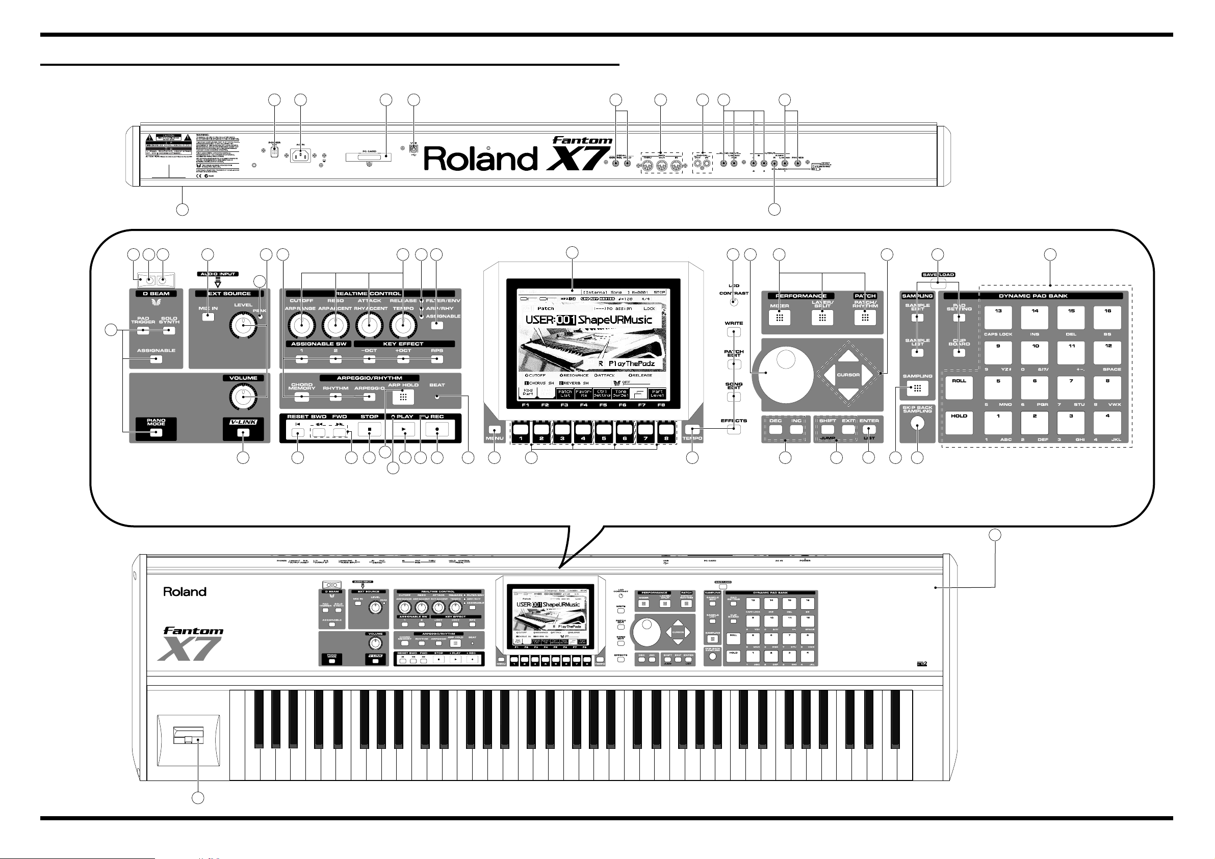
LOCATION OF CONTROLS
fig.panel-x7
[REAR]
[TOP]
9
27
26
25
10
9
3
76 8 9 4 10 12 20 18
28
29
30
2
3331 32
34
5 22 9
35
24
11 11 14 15 1216 191013 13 12 13 13 2318
18
17
12
1
21
5
Page 5

Mar.2004
LOCATION OF CONTROLS PARTS LIST
[TOP]
PART CODE CATEGORY PART NAME DESCRIPTION Q’TY
NO
1 03562501 CASING TOP PANEL 1
2 03562112 CASING DISPLAY COVER 1
2 03560889 DISPLAY UNIT LCD KCG057QV1DB-G00 1
2 03565245 CASING DISPLAY ESCT
3 03565234 KNOB,BUTTON J R-KNOB SF-ELA BLK/SLV 2
3 03126167 POTENTIOMETER 12M/M ROTARY POTENTIOMETER EVJY10FB6A24 2
4 03565234 KNOB,BUTTON J R-KNOB SF-ELA BLK/SLV 4
4 03126178 POTENTIOMETER 9M/M ROTARY POTENTIOMETER EVUF2JFK3B14 4
5 22485303 KNOB,BUTTON D R-KNOB(ALPHA-DIAL) L BLK 248-303 1
5 01905467 ENCODER ROTARY ENCODER EVE GC1 F20 24B 1
6 01343089 CASING ESCUTCHEON D-BEAM CONTROLLER ESCT BLK 1
7 01900612 DIODE DIODE TPS611 1
7 12169368 MISCELLANEOUS LED SPACER LDS-40B 1
8 03126134 DIODE LED TLN233 1
8 02230578 MISCELLANEOUS LED SPACER LDS-50R 1
9 03120890 KNOB,BUTTON D S-KEYTOP SX1H-B GRS 18
9 02125167 DIODE LED (YELOW) SLI-343DCT32W 18
9 01340290 SWITCH TACT SWITCH EVQ11A H=5.0 18
10 01011656 DIODE LED (RED) SLR-332VR3F 5
10 12169406 MISCELLANEOUS LED SPACER 5
11 03120890 KNOB,BUTTON D S-KEYTOP SX1H-B GRS 1
11 03122112 DIODE LED(BLUE) SLR-343BBT3F 1
11 01340290 SWITCH TACT SWITCH EVQ11A H=5.0 1
12 03120890 KNOB,BUTTON D S-KEYTOP SX1H-B GRS 9
12 01340290 SWITCH TACT SWITCH EVQ11A H=5.0 9
13 03120889 KNOB,BUTTON D S-KEYTOP SX2H-B GRS 7
13 01340290 SWITCH TACT SWITCH EVQ11A H=5.0 14
14 03565190 KNOB,BUTTON KEYTOP STOP 1
14 00894645 SWITCH TACT SWITCH SKECAF WITHOUT LED 1
15 00894645 SWITCH TACT SWITCH SKECAF WITHOUT LED 1
15 03565212 KNOB,BUTTON KEYTOP PLAY 1
16 00894645 SWITCH TACT SWITCH SKECAF WITHOUT LED 1
16 03565223 KNOB,BUTTON KEYTOP REC 1
17 01012078 DIODE LED (GREEN) SLR-332MG3F 1
17 12169406 MISCELLANEOUS LED SPACER 1
18 01783923 KNOB,BUTTON N S-KEYTOP MD1H 5
18 02894090 DIODE LED (ORNG) SLR-343DUT32 5
19 01455901 MISCELLANEOUS LED SPACER LH-36-9 1
19 00127367 DIODE LED (RED/GREEN) SPR-39MVW 1
20 03562256 POTENTIOMETER ROTARY POTENTIOMETER EVUF2AE20B14 1
21 03234723 POWER SUPPLY UNIT BENDER PB-H0204 1
22 01234090 KNOB,BUTTON D T-KEYTOP MX4B BLK 1
22 01340290 SWITCH TACT SWITCH EVQ11A H=5.0 4
23 02013090 KNOB,BUTTON F C-KEYTOP MX1H CLR 1
23 03122112 DIODE LED(BLUE) SLR-343BBT3F 1
23 01340290 SWITCH TACT SWITCH EVQ11A H=5.0 1
24 03562145 KNOB,BUTTON RUBBER SW 1
24 03122067 CASING RUBBER SW ESCT 1
24 03128767 PICK UP,SENSOR PRESSURE SENSOR SHEET 1
[REAR]
NO PART CODE CATEGORY PART NAME DESCRIPTION Q’TY
25 72565734 CASING BOTTOM COVER ASSY 1
26 32490595 KNOB,BUTTON P S-KEY MX BLK 1
26 ******** SWITCH PUSH SWITCH 1
27 ******** AC INLET, OUTLET AC INLET 1
When you order the above parts, please order the 72564312 INLET BOARD ASSY.
28 03562156 CASING PC CARD ESCUTCHEON BLK 1
28 02900867 JACK,EXT TERMINAL CARD EJECTOR SCAB1A5600 1
29 02781189 JACK,EXT TERMINAL USB CONNECTOR YKF45-0021 1
30 13449275 JACK,EXT TERMINAL 6.5MM JACK YKB21-5074 2
31 13429274 JACK,EXT TERMINAL MIDI SOCKET YKF51-5041 1
32 03231812 JACK,EXT TERMINAL RCA(PIN) YKC21-4173 1
33 13449283 JACK,EXT TERMINAL 6.5MM JACK HLJ7101-01-3010 4
34 13449258 JACK,EXT TERMINAL 6.5MM JACK HLJ4306-01-3080 1
35 13449284 JACK,EXT TERMINAL 6.5MM JACK HLJ7001-01-3010 2
6
Page 6

FANTOM-X7
7
Page 7
Mar.2004
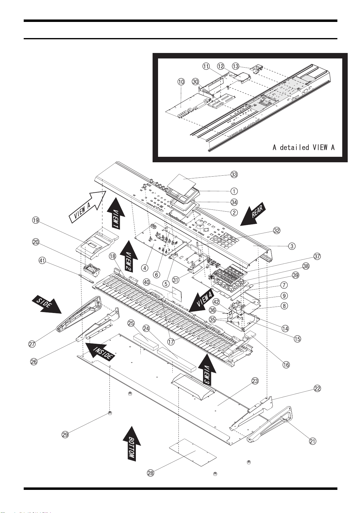
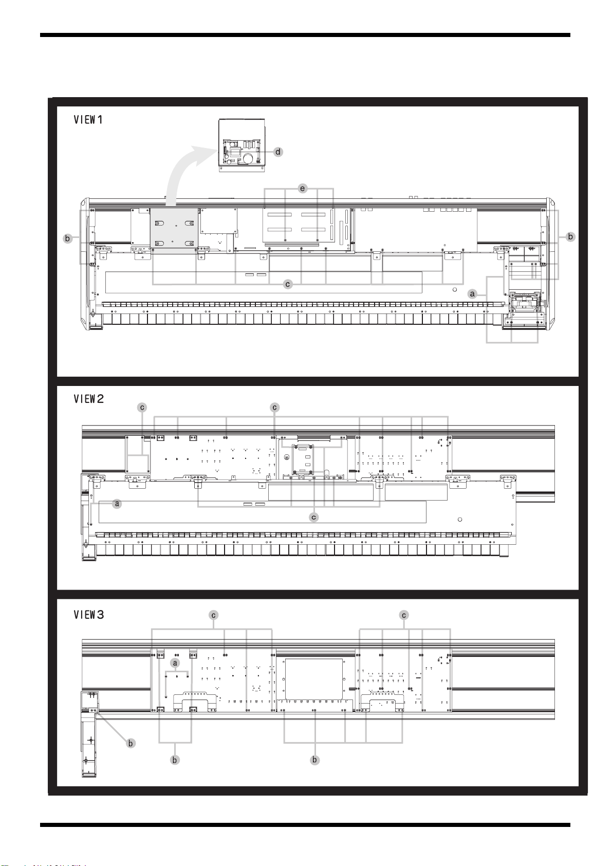
EXPLODED VIEW
fig.FANTOM-X7_explo1_E
8
Page 8
FANTOM-X7
fig.FANTOM-X7_explo2_E
9
Page 9
Mar.2004
fig.FANTOM-X7_explo3_E
10
Page 10

FANTOM-X7
EXPLODED VIEW PARTS LIST
[PARTS]
PART CODE CATEGORY Part name Description Q'TY
No
1 03565245 CASING DISPLAY ESCT 1
2 03560889 DISPLAY UNIT LCD KCG057QV1DB-G00 1
3 03562501 CASING TOP PANEL 1
4 72564256 PWB ASSY PANEL-A KEYTOP ASSY 1
5 03562123 CHASSIS DISPLAY HOLDER 1
6 72564278 PWB ASSY PANEL-B KEYTOP ASSY 1
7 72564334 PWB ASSY PANEL-C KEYTOP ASSY 1
8 72564212 PWB ASSY INVERTER BOARD ASSY 1
9 03567789 MISCELLANEOUS INSULATING SHEET 1
10 72565812 PWB ASSY JACK BOARD ASSY 1
11 72564734 PWB ASSY MAIN BOARD ASSY 1
NOTE:When you replace the MAIN BOARD ASSY for repairng, be sure to perform the
"MAIN BOARD SETTING FOR SELECTING MODEL PROCEDURE"(to see P24).
In addition, we supply the MAIN BOARD ASSY of FANTOM-X6 setting for spare parts.
12 72564245 PWB ASSY PC CARD BOARD ASSY 1
13 72564312 PWB ASSY INLET BOARD ASSY 1
14 01785823 POWER SUPPLY UNIT SWITCHING REGULATOR A1DU2L3B034 1
15 03125845 CHASSIS PWR SPLY HOLDER 1
16 03126556 CASING END BLOCK 1
17 02674034 CHASSIS PANEL HOLDER 2
18 72567090 KEYBOARD ASSY KEYBOARD ASSY SK-976-C 1
19 03126567 CASING BENDER PANEL 1
20 03234723 BENDER UNIT BENDER PB-H0204 1
21 03122045 CASING SIDE COVER R 1
22 03125812 CHASSIS SIDE HOLDER R 1
23 72565734 CASING BOTTOM COVER ASSY 1
24 03670689 MISCELLANEOUS CUSHION A 1
25 03670701 MISCELLANEOUS CUSHION B 1
26 03125801 CHASSIS SIDE HOLDER L 1
27 03122034 CASING SIDE COVER L 1
28 03017778 CASING EXP COVER 1
29 12359139 MISCELLANEOUS RUBBER FOOT FF-018 BLK 4
30 72235090 PWB ASSY EXP BASE BOARD ASSY 1
31 72564223 PWB ASSY LCD BOARD ASSY 1
32 03670734 MISCELLANEOUS SPACER M3X20 HEX 1
33 03562112 CASING DISPLAY COVER 1
34 03567790 CASING DISPLAY CUSHION 4
35 03017867 MISCELLANEOUS CARD SPACER MPS-10-0 2
36 40120967 MISCELLANEOUS COATING CLIP CS-3 1
37 03122067 CASING RUBBER SW ESCT 1
38 03562145 KNOB,BUTTON RUBBER SW 1
39 03128767 PICK UP,SENSOR PRESSURE SENSOR SHEET 1
40 03670712 MISCELLANEOUS CUSHION C 1
41 02673945 MISCELLANEOUS STAY BENDER 1
42 01455523 MISCELLANEOUS CORD BUSHING EDS-1717U 1
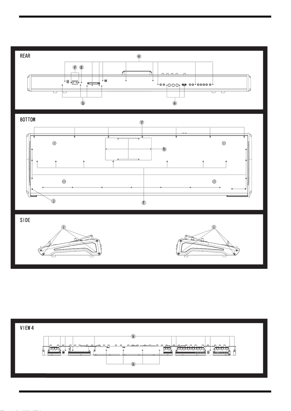
[SCREW]
No PART CODE Part name Description Q'TY
a 40011312 SCREW 3X8 BINDING TAPTITE P BZC 23
b 40011101 SCREW 3X8 BINDING TAPTITE B BZC 18
c 40011056 SCREW 3X6 BINDING TAPTITE B ZC 57
d 40017934 SCREW M3X6 PAN MACHINE W/SW+PW FE ZC 4
e 40011490 SCREW M3X6 PAN MACHINE W/SW BZC 22
f 40011123 SCREW 4X8 BINDING TAPTITE B BZC 6
g 40010345 SCREW M4X10 BINDING MACHINE FE BZC 1
h 40013078 SCREW M3X10 PAN MACHINE W/SW FE ZC 1
i 40454045 SCREW 3X8 FLAT TAPTITEB NI FLANGE SOCKET 8
j 40012501 SCREW M4X12 BINDING TAPTITE P FE BZC 1
k 40011067 SCREW 3X8 BINDING TAPTITE B FE ZC 16
l 22150501 STAND OFF M3 L10C 4
11
Page 11
Mar.2004
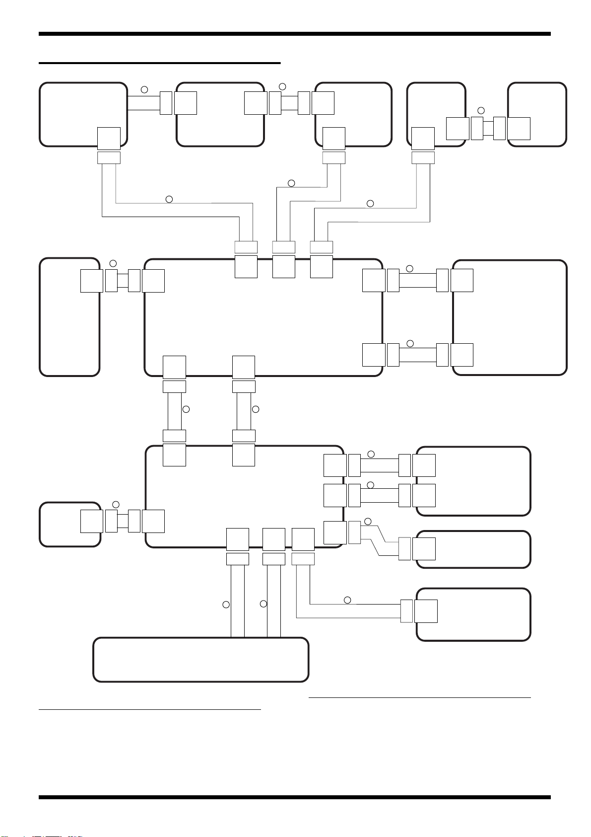
WIRING DIAGRAM
fig.wiring-x7
LCD
CN102
R
LCD
CN304
BOARD
E 20PIN
CN305
D 2PIN
C 2PIN
INVERTER
CN404
BOARD
CN403
B 7PIN
POWER
SWITCH
CN2
CN1
A 2PIN
INLET
BOARD
CN601
PC CARD
BOARD
BENDER
CN2
CN1
H 50PIN
O 4PIN
CN18
CN8
CN9
CN1
CN20
MAIN BOARD
CN22
I 18PIN
CN18
JACK BOARD
J 15PIN
CN4CN3 CN7
CN21
CN10
CN5
CN10
CN6
CN4
CN5
K 38PIN
L 12PIN
M 10PIN
F 34PIN
G 34PIN
CN2
PANEL A
BOARD
CN11
PANEL B
CN201
BOARD
CN5
EXPANSION
BOARD
CN6
P 16PIN
KEYBOARD UNIT
NO
PART CODE PART NAME DESCRIPTION
A. 03120801 WIRING W3
B. 02679390 WIRING 7X150-P2.5-XHP-XHP-F
C. 03564990 WIRING W3
D. 03564912 WIRING W1
E. 03565267 BAN CARD BNCD-P=0.50-K-20-320
F. 03129323 BAN CARD BNCD-P=1.00-K-34-60
G. 03129323 BAN CARD BNCD-P=1.00-K-34-60
H. 03565290 BAN CARD BNCD-S-P=0.50-K-50-140
12
Q 22PIN
N 40PIN
PANEL C
CN501
BOARD
NO PART CODE PART NAME DESCRIPTION
I. 03566590 BAN CARD BNCD-P=1.00-K-18-500
J. 03564945 WIRING W2
K. 03129290 BAN CARD BNCD-P=1.00-K-38-400
L. 02344023 WIRING 12X200-P2.0-PHR-PHR-F
M. 03129301 BAN CARD BNCD-P=1.00-K-10-400
N. 03129312 BAN CARD BNCD-P=1.00-K-40-700
O. 02342034 WIRING 4X300-P2.0-PHR-PHR-F
P. 03565312 BAN CARD BNCD-P=1.25-K-16-180
Q. 03565334 BAN CARD BNCD-P=1.25-K-22-300
R. This wiring is included the LCD UNIT.
Page 12

FANTOM-X7
13
Page 13

Mar.2004
PARTS LIST
fig.part1e
SAFETY PRECAUTIONS:
The parts marked have
safety-related characteristics. Use
only listed parts for replacement.
NOTE: The parts marked # are new. (initial parts)
CASING
# 03562501 TOP PANEL 1
# 72565734 BOTTOM COVER ASSY 1
# ******** BOTTOM COVER 1
CHASSIS
03562112
03017778 EXP COVER 1
03567790 DISPLAY CUSHION 4
03122034 SIDE COVER L 1
03122045 SIDE COVER R 1
03565245 DISPLAY ESCT 1
03122067 RUBBER SW ESCT 1
03126556 END BLOCK 1
03126567 BENDER PANEL 1
NOTE: ‘BOTTOM COVER ASSY’ includes the following parts.
12359139 RUBBER FOOT FF-018 BLK 4
03125845
03562123 DISPLAY HOLDER 1
02674034 PANEL HOLDER 2
03125801 SIDE HOLDER L 1
03125812 SIDE HOLDER R 1
CONSIDERATION ON PARTS ORDRING
When ordering any parts listed in the parts list, please specify the following items in the order sheet.
Failure to completely fill the above items with correct number and description will result in delayed or even
undelivered replacement.
DISPLAY COVER 1
PWR SPLY HOLDER 1
QTY PART NUMBER DESCRIPTION MODEL NUMBER
Ex. 10 22575241 Sharp Key C-20/50
15 2247017300 Knob (orange) DAC-15D
KNOB, BUTTON
32490595
01234090 D T-KEYTOP MX4B BLK 1
03565234 J R-KNOB SF-ELA BLK/SLV 6
22485303 D R-KNOB(ALPHA-DIAL) L BLK 248-303 1
03562145 RUBBER SW 1
SWITCH
01340290
00894645 TACT SWITCH SKECAF WITHOUT LED SW21,SW23,SW22 on PANEL-A BOARD 3
JACK, EXT TERMINAL
02900867
02900834 CARD CONECTR SCAA1A2300 CN1 on PC CARD BOARD 1
13429274 MIDI SOCKET YKF51-5041 JK1 on JACK BOARD 1
03231812 RCA(PIN) YKC21-4173 JK12 on JACK BOARD 1
13449258 6.5MM JACK HLJ4306-01-3080 JK7 on JACK BOARD 1
13449275 6.5MM JACK YKB21-5074 JK2,JK3 on JACK BOARD 2
13449283 6.5MM JACK HLJ7101-01-3010 JK9,JK10,JK8,JK11 on JACK BOARD 4
13449284 6.5MM JACK HLJ7001-01-3010 JK6,JK4 on JACK BOARD 2
02781189 USB CONNECTOR YKF45-0021 JK1 on MAIN BOARD 1
02781101 USB CONNECTOR YKF45-0020 1
P S-KEY MX BLK 1
TACT SWITCH EVQ11A H=5.0 SW2,SW3,SW13,SW20,SW19,SW18,SW17,S
W16,SW1,SW14,SW4,SW12,SW11,SW10,S
W8,SW7,SW6,SW5,SW15 on PANEL-A
BOARD,
SW201,SW202,SW203,SW204,SW210,SW20
5,SW206,SW207,SW208,SW209 on PANELB BOARD
,SW516,SW503,SW518,SW514,SW513,SW51
2,SW520,SW515,SW521,SW522,SW523,SW5
19,SW506,SW511,SW501,SW517,SW505,SW
507,SW508,SW509,SW510,SW502,SW504 on
PANEL-C BOARD
CARD EJECTOR SCAB1A5600 1
10
+19
+23
DISPLAY UNIT
14
03560889
NOTE: Replacement KCG057QV1DB-G00 should be made on a unit base.
KCG057QV1DB-G00 LCD 1
Page 14

FANTOM-X7
POWER SUPPLY UNIT
BENDER UNIT
KEYBOARD ASSY
# 72567090 SK-976-C KEYBOARD ASSY 1
PCB ASSY
01785823 A1DU2L3B034 SWITCHING REGULATOR 1
NOTE: Replacement A1DU2L3B034 should be made on a unit base.
03234723 PB-H0204 BENDER 1
NOTE: Replacement PB-H0204 should be made on a unit base.
NOTE: See ‘KEYBOARD PARTS LIST’ for details.
72235090 EXP BASE BOARD ASSY 1
NOTE: ‘EXP BASE BOARD ASSY’ includes the following parts.
02019034 PWB SPACER RSPLS-12L 4
01902756 PWB SPACER RSPS-12L 4
72564278 PANEL-B KEYTOP ASSY 1
NOTE: ‘PANEL-B KEYTOP ASSY’ includes the following parts.
03120889 D S-KEYTOP SX2H-B GRS 4
03120890 D S-KEYTOP SX1H-B GRS 2
72564256 PANEL-A KEYTOP ASSY 1
NOTE: ‘PANEL-A KEYTOP ASSY’ includes the following parts.
01343089 ESCUTCHEON
03565223 KEYTOP REC 1
03565212 KEYTOP PLAY 1
03565190 KEYTOP STOP 1
03120890 D S-KEYTOP SX1H-B GRS 16
03120889 D S-KEYTOP SX2H-B GRS 1
01783923 N S-KEYTOP MD1H 1
12169368 LED SPACER LDS-40B 1
12169406 LED SPACER 6
02230578 LED SPACER LDS-50R 1
01455901 LED SPACER LH-36-9 1
D-BEAM CONTROLLER ESCT BLK
1
72564245 PC CARD BOARD ASSY 1
NOTE: ‘PC CARD BOARD ASSY’ includes the following parts.
03562156 PC CARD ESCUTCHEON BLK 1
03562167 PC CARD HOLDER HOLDER 1
40343367 SCREW M2X14
72564212 INVERTER BOARD ASSY 1
72564223 LCD BOARD ASSY 1
72564312 INLET BOARD ASSY 1
72564334 PANEL-C KEYTOP ASSY 1
NOTE: ‘PANEL-C KEYTOP ASSY’ includes the following parts.
01783923 N S-KEYTOP MD1H 4
02013090 F C-KEYTOP MX1H CLR 1
03120889 D S-KEYTOP SX2H-B GRS 2
03120890 D S-KEYTOP SX1H-B GRS 10
02123012 ENCODER HOLDER 1
# 72565812 JACK BOARD ASSY 1
NOTE: ‘JACK BOARD ASSY’ includes the following parts.
40342856 COATING CLIP CP-1S 2
72564734 MAIN BOARD ASSY 1
NOTE: ‘MAIN BOARD ASSY’ includes the following parts.
03670045 SHEET K4E(10)-55X15T15S 1
03670034 SHEET K4E(10)-23X20T15S 1
NOTE: When you replace the MAIN BOARD ASSY for repairng, be sure to perform the
"MAIN BOARD SETTING FOR SELECTING MODEL PROCEDURE"(to see P24).
In addition, we supply the MAIN BOARD ASSY of FANTOM-X6 setting for spare parts.
IC
02675689 HD74LV245ATELL IC (CMOS) IC1,IC2,IC3 on EXP BASE BOARD,
15189186 UPC4570C IC (BIPOLAR OP AMP) IC4,IC2,IC3 on PANEL-A BOARD 3
01785012 HA17324 IC (BIPOLAR OP AMP) IC1 on PANEL-A BOARD 1
01783589 HD74HC4052FPEL IC (CMOS) IC14 on JACK BOARD ,IC503,IC501 on
PAN MACHINE W/SW+SMALL PWZC
IC3,IC44,IC40,IC8,IC7,IC5 on MAIN
BOARD
PANEL-C BOARD
4
3
+6
2
+1
15
Page 15

Mar.2004
IC
02894301 HA17324ARPEL(FP-14DN) IC (CMOS OP) IC502 on PANEL-C BOARD 1
03127267 HD6433061G45FP IC (16BIT CPU) IC2 on JACK BOARD 1
00129278 SSC1080F0B IC IC5 on JACK BOARD 1
15269219H0 HD74LS05FPEL IC (TTL) IC12 on JACK BOARD 1
01121834 TC7W74FU TE12L IC IC6 on JACK BOARD 1
01783656 HD74HC4053FPEL IC CMOS IC23 on JACK BOARD 1
15249104 TC7S04F(TE85L) IC (CMOS) IC22 on JACK BOARD 1
00567534 TC74VHC138F(EL) IC (CMOS) IC9,IC8 on JACK BOARD 2
01908678 TC74VHCU04FT(EL) IC (CMOS) IC17 on JACK BOARD 1
02451712 HD74LV14ATELL IC (CMOS) IC1 on JACK BOARD 1
15189261 M5218AFP-600E IC (BIPOLAR OP AMP) IC71,IC70,IC68,IC61,IC59 on MAIN
BOARD,
IC18,IC19,IC16,IC24,IC25 on JACK BOARD
15289105 UPC4570G2-E2 IC (BIPOLAR OP AMP) IC20 on JACK BOARD 1
15289151 NJM2904M-TE3 IC (OP AMP) IC7,IC10,IC15,IC21 on JACK BOARD 4
02900545 PC410LKNIP IC (PHOTO COUPLER) IC11 on JACK BOARD 1
02903723 HD6417706 IC (32BIT CPU) IC1 on MAIN BOARD 1
02900978 M66291GP IC (USB CONTROLLER) IC56 on MAIN BOARD 1
03456167 S1D13705F00A200 IC (LCD-DRIVER CPU PERIPH) IC128 on MAIN BOARD 1
03566067 T6TV2TBG-0002(WX) IC (CUSTOM) IC102 on MAIN BOARD 1
03124989 UPD23C128040ALGY-535-MJH IC (MASK ROM) IC33 on MAIN BOARD 1
03124978 UPD23C128040ALGY-536-MJH IC (MASK ROM) IC28 on MAIN BOARD 1
03562234 UPD23C128040BLGY-818-MJH IC (MASK ROM) IC103 on MAIN BOARD 1
03562223 UPD23C128040BLGY-819-MJH IC (MASK ROM) IC104 on MAIN BOARD 1
******** MBM29LV160BE70TN-E1 IC (FLASH MEMORY) IC19 on MAIN BOARD 1
03560589 TC58DVM92A1TG00BBH IC (FLASH MEMORY) IC53 on MAIN BOARD 1
03237689 M12L64164A-7T IC (MEMORY DRAM) IC106 on MAIN BOARD 1
03342201 K4S281632E-TC75 IC (SDRAM) IC20,IC2,IC24,IC6 on MAIN BOARD 4
03017590 UDA1351TS IC (DIR DAC) IC75 on MAIN BOARD 1
03231701 AK4527BVQ IC (AD/DA) IC60 on MAIN BOARD 1
01458401 TC74LVX4245FS(EL) IC (TTL) IC114,IC112 on MAIN BOARD 2
03231678 TC7WZ74FU(TE12L) IC (CMOS) 1
03459745 HD74LVC540ATELL-E IC (CMOS) IC111 on MAIN BOARD 1
03346267 HD74LV273ATELL-E IC (CMOS) IC90 on MAIN BOARD 1
01901623 TC74LVXC3245FS IC (CMOS) 2
01677689 HD74HC238FPEL IC (CMOS) IC96 on MAIN BOARD 1
01349590 TC7WU04FU(TE12L) IC (CMOS) IC16,IC26 on MAIN BOARD 2
03015390 TC74HCT273AF(EL) IC (CMOS) IC54 on MAIN BOARD 1
01455312 TC7WH74FU IC (CMOS) IC115 on MAIN BOARD 1
01348956 TC7SH00FU(TE85L) IC (CMOS) IC105 on MAIN BOARD 1
01348945 TC7SH32FU(TE85L) IC (CMOS) IC130 on MAIN BOARD 1
01675034 TC74VHC138FT(EL) IC CMOS IC99,IC98 on MAIN BOARD 2
01675023 TC74VHC139FT(EL) IC (CMOS) IC107,IC108,IC110 on MAIN BOARD 3
01783523 TC74VHCT245AFT(EL) IC (CMOS) IC119,IC118,IC117 on MAIN BOARD 3
01890367 TC74VHC175FT(EL) IC (CMOS) IC52 on MAIN BOARD 1
01348901 TC7SH04FU(TE85L) IC (CMOS) 1
03015234 HD74LV32ATELL IC (CMOS) IC113,IC14,IC50 on MAIN BOARD 3
02451923 HD74LV74ATELL IC (CMOS) 1
02675656 HD74LV11ATELL IC (CMOS) IC92 on MAIN BOARD 1
02456756 TC74VHCT04AFT(EL) IC (CMOS) IC9 on MAIN BOARD 1
02451912 HD74LV00ATELL IC (CMOS) IC74,IC116 on MAIN BOARD 2
02451690 HD74LV08ATELL IC (CMOS) IC94 on MAIN BOARD 1
02129334 TC7WH08FU(TE12L) IC (CMOS) IC120 on MAIN BOARD 1
02675667 HD74LV21ATELL IC (CMOS) IC91 on MAIN BOARD 1
02675645 HD74LV04ATELL IC (CMOS) IC17,IC10 on MAIN BOARD 2
00344390 TA7805F(TE16L) IC (REGULATOR) IC58 on MAIN BOARD 1
02671545 PQ070XZ01ZP IC (REGULATOR) IC101,IC57 on MAIN BOARD 2
03125089 PQ1CY1032ZP IC (SWITCHING REGULATOR) IC100 on MAIN BOARD 1
01785178 TC9271FS IC (DIGITAL OUT IF) IC62 on MAIN BOARD 1
02900690 P2027A-08TR IC IC89 on MAIN BOARD 1
15199937 M51953BFP-600C IC (RESET) IC18 on MAIN BOARD 1
5
+5
TRANSISTOR
16
03126145 2SA933ASTPR TRANSISTOR Q2 on PANEL-A BOARD 1
15129626 2SD1468S TP Q TRANSISTOR Q3 on PANEL-A BOARD 1
15319101 2SC2412KR T146 TRANSISTOR Q42 on JACK BOARD ,Q501 on PANEL-C
BOARD
00901523 2SA1681 (SC-62)(POW SW) TRANSISTOR Q34 on JACK BOARD 1
15309101 2SA1037AKT146R TRANSISTOR Q11,Q12 on MAIN BOARD,
Q28 on JACK BOARD
01121289 2SC4081 T106 QRS TRANSISTOR Q23,Q24,Q19,Q18,Q1 on JACK BOARD 5
02671023 2SC3052-T12-1E TRANSISTOR Q41,Q35 on JACK BOARD 2
15319105 2SC3326-A TRANSISTOR Q27,Q40,Q39,Q38,Q37,Q33,Q32,Q26,Q25,Q
30 on JACK BOARD
15329103T0 2SK880-GR(TE85R) FET Q7,Q8,Q10,Q9 on MAIN BOARD,
Q31 on JACK BOARD
00239801 DTA114EU T-106 TRANSISTOR Q20 on JACK BOARD 1
02451378 RN2427 TRANSISTOR Q3,Q4,Q5,Q6,Q7,Q8,Q9 on JACK BOARD 7
15329533 RN2307(TE85R) TRANSISTOR Q21 on JACK BOARD 1
00239812 DTC114EUT106 TRANSISTOR Q14,Q15,Q16,Q18,Q13 on MAIN BOARD,
Q17,Q16,Q15,Q14,Q13,Q12,Q11,Q10 on
JACK BOARD
1
+1
1
+2
10
1
+4
8
+5
Page 16

FANTOM-X7
TRANSISTOR
DIODE
02671267 RT1N141C-T12-1 TRANSISTOR Q36,Q29 on JACK BOARD 2
15329511 DTC114TKT146 DIGITAL TRANSISTOR Q43 on JACK BOARD 1
15329531 RN1308-TE85R TRANSISTOR Q22 on JACK BOARD 1
02900778 PW MOSFET XP132A1275SR TRANSISTOR Q17 on MAIN BOARD 1
15019126 1SS133 T-77 SWITCHING DIODE D18,D29,D28,D27,D26,D25,D24,D23,D22,D
01900612 TPS611 DIODE Q1 on PANEL-A BOARD 1
03126134 TLN233 LED LED23 on PANEL-A BOARD 1
03122112 SLR-343BBT3F LED(BLUE) LED14 on PANEL-A BOARD,
02894090 SLR-343DUT32 LED (ORNG) LED18 on PANEL-A BOARD,
02125167 SLI-343DCT32W LED (YELOW) LED15,LED2,LED16,LED11,LED10,LED9,L
01012078 SLR-332MG3F LED (GREEN) LED19 on PANEL-A BOARD 1
01011656 SLR-332VR3F LED (RED) LED21,LED13,LED12,LED6,LED20 on
00127367 SPR-39MVW LED (RED/GREEN) LED22 on PANEL-A BOARD 1
15339130 MA142WK-(TX) ARRAY DIODE DA8,DA6,DA7,DA9 on MAIN BOARD,
03564390 SML-212DTT86 LED LED520,LED527,LED518,LED528,LED504,L
01121323 DA204U T106 DIODE ARRAY DA16 on JACK BOARD 1
01121334 DAN202U T106 ARRAY DIODE DA10 on JACK BOARD 1
01897189 MA147-(TX) ARRAY DIODE DA3,DA2,DA5,DA4 on MAIN BOARD,
00129767 RD10M-T1B B2 ZENER DIODE D1 on JACK BOARD 1
01780045 RB051L-40 SCHOTTKY DIODE D4 on MAIN BOARD 1
21,D1,D19,D17,D16,D6,D2,D3,D20,D5,D15,
D7,D8,D10,D11,D12,D13,D14,D4 on PAN-
EL-A BOARD,
D204,D201,D203,D205,D206,D207,D208,D2
09,D210,D202 on PANEL-B BOARD
LED522 on PANEL-C BOARD
LED501,LED523,LED508,LED515 on PAN-
EL-C BOARD
ED8,LED7,LED5,LED4,LED3,LED1,LED17
on PANEL-A BOARD,
LED509,LED502,LED510,LED516,LED503
on PANEL-C BOARD
PANEL-A BOARD
DA3,DA1,DA4,DA2 on JACK BOARD
,DA503,DA505,DA502,DA501,DA504,DA51
3,DA512,DA511,DA510,DA509,DA508,DA5
07,DA506 on PANEL-C BOARD
ED526,LED525,LED524,LED521,LED519,LE
D517,LED514,LED513,LED512,LED511,LE
D507,LED505,LED506 on PANEL-C
BOARD
DA5,DA6,DA7,DA9,DA11,DA12,DA13,DA
14,DA15,DA8 on JACK BOARD
10
+28
1
+1
1
+4
13
+5
5
13
+4
+4
18
10
+4
RESISTOR
00567289 RPC05T 103 J MTL.FILM RESISTOR R2,R6,R10 on EXP BASE
BOARD,R118,R119,R134,R139,R150,R164,R
165,R166,R174,R114,R176,R44,R188,R175,
R110,R109,R105,R84,R82,R195,R43,R42,R40,
R39,R25,R13,R414,R80,R437,R393,R395,R41
3,R428,R430,R392,R436,R446,R438,R445,R4
49,R453,R455,R238,R396,R431,R266,R451,R
244,R247,R390,R243,R313,R358,R363,R364,
R365,R381,R241,R384,R387,R388,R248 on
MAIN BOARD
,R14,R12,R13,R38,R86,R88,R96,R106,R127,R
135,R148,R165,R202,R203,R207,R208,R10,R
5,R182,R2,R11 on JACK BOARD ,R517 on
PANEL-C BOARD
02457790 MNR14 EOAB J 330 RESISTOR-ARRAY 2
01906678 MNR14 EOAB J 103 RESISTOR-ARRAY RA1,RA16 on JACK BOARD 8
01906667 MNR14 EOAB J 100 RESISTOR-ARRAY RA24,RA6,RA2,RA25,RA3,RA4 on JACK
BOARD
13749190 SR50TR 100 J CARBON RESISTOR R8,R7 on PANEL-A BOARD 2
13749765T0 SR25TRE 470 J CARBON RESISTOR R23 on PANEL-A BOARD 1
13749771T0 SR25TRE 820 J CARBON RESISTOR R22 on PANEL-A BOARD 1
13749773T0 SR25TRE 101 J CARBON RESISTOR R2,R13,R4,R3,R1 on PANEL-A BOARD 5
13749779T0 SR25TRE 181 J CARBON RESISTOR R17 on PANEL-A BOARD 1
13749781T0 SR25TRE 221 J CARBON RESISTOR R21,R16 on PANEL-A BOARD 2
13749797T0 SR25TRE 102 J CARBON RESISTOR R14,R19 on PANEL-A BOARD 6
13749799T0 SR25TR 122J CARBON RESISTOR R15 on PANEL-A BOARD 1
13749805T0 SR25TRE 222 J CARBON RESISTOR R6 on PANEL-A BOARD 1
13749811T0 SR25TRE 392 J CARBON RESISTOR R5,R10 on PANEL-A BOARD 2
13749821T0 SR25TRE 103 J CARBON RESISTOR R30,R28,R26,R18,R11,R24 on PANEL-A
BOARD
13749837T0 SR25TRE 473 J CARBON RESISTOR R12 on PANEL-A BOARD 1
13749839T0 SR25TRE 563 J CARBON RESISTOR R20 on PANEL-A BOARD 1
13749859T0 SR25TRE 394 J CARBON RESISTOR R9 on PANEL-A BOARD 1
3
+1
+21
+62
+2
22
+6
6
17
Page 17

Mar.2004
RESISTOR
02904445 EXB2HV330JV RESISTOR-ARRAY RA4,RA28,RA21,RA10 on MAIN BOARD,
RA5,RA1,RA2,RA3,RA4 on PC CARD
BOARD
00567456 RPC05T 224 J MTL.FILM RESISTOR R51 on JACK BOARD ,R524 on PANEL-C
BOARD
00566967 RPC05T 470 J MTL.FILM RESISTOR R284,R292,R79,R282,R283,R337,R290,R285,
R400,R338,R401,R294,R293,R291,R289,R288,
R287,R286,R399 on MAIN BOARD,
R514,R513 on PANEL-C BOARD
01011856 RPC05T 0R0 J MTL.FILM RESISTOR R68,R412,R427,R429,R439,R456,R73,R411,R
41,L18,L17,L16,R147,R113,R87,R305,R136,R
140,R144,R157,R214,R419,R304,R410,R306,
R307,R308,R309,R397,R403,R409,R239,R141
on MAIN BOARD
,R37,R3,R50,R73,R97,R99,R160,R178,R185,R
217,R227,R236,R33,R48,R34,R19,R18,R16,R1
5,R6 on JACK BOARD
,R522,R516,R523,R515 on PANEL-C
BOARD
00567290 RPC05T 123 J MTL.FILM RESISTOR R58 on JACK BOARD ,R521 on PANEL-C
BOARD
00567367 RPC05T 393 J MTL.FILM RESISTOR R518 on PANEL-C BOARD 1
00567023 RPC05T 101 J MTL.FILM RESISTOR R315,R316,R183,R246,R245,R187,R182,R181
,R58,R57,R51,R320,R318,R54,R321,R331,R36
9,R370,R371,R372,R375,R378,R454,R317 on
MAIN BOARD,
R45,R53,R71,R77,R156,R177,R184,R231,R31
on JACK BOARD,
R505,R501,R504,R507,R508,R510,R511,R502
on PANEL-C BOARD
00567501 RPC05T 474 J MTL.FILM RESISTOR R506,R509,R503,R512 on PANEL-C BOARD 4
01450490 NTH5G1M33B103J THERMISTOR RESISTOR R519 on PANEL-C BOARD 1
03128889 EXBV8V222JV RESISTOR-ARRAY RA502,RA503,RA504,RA501 on PANEL-C
BOARD
15399565 RPC18T 470 J CARBON RESISTOR R220,R63,R64,R65,R219,R221,R222,R62 on
JACK BOARD
15399561 RPC18T 330 J CARBON RESISTOR R61 on JACK BOARD 1
15399567 RPC18T 560 J CARBON RESISTOR 4
15399573 RPC18T 101 J CARBON RESISTOR R226 on JACK BOARD 1
15399583 RPC18T 271 J CARBON RESISTOR R67,R68 on JACK BOARD 2
00566956 RPC05T 390 J MTL.FILM RESISTOR R70,R69 on JACK BOARD 2
00567001 RPC05T 750 J MTL.FILM RESISTOR R235,R126 on JACK BOARD 2
00567034 RPC05T 121 J MTL.FILM RESISTOR R75 on JACK BOARD 1
00567067 RPC05T 221 J MTL.FILM RESISTOR R421,R422 on MAIN BOARD,
R80,R125,R82,R81,R79 on JACK BOARD
00567078 RPC05T 271 J MTL.FILM RESISTOR R72,R90 on JACK BOARD 2
00567089 RPC05T 331 J MTL.FILM RESISTOR R206,R232,R168,R153,R140,R130,R211 on
JACK BOARD
00567112 RPC05T 471 J MTL.FILM RESISTOR R177,R169,R179,R167 on MAIN BOARD,
R27,R21,R20,R26,R28,R29,R30,R57,R84,R91,
R92,R100,R108,R25 on JACK BOARD
00567134 RPC05T 681 J MTL.FILM RESISTOR R55,R158,R101 on MAIN BOARD,
R212,R167,R152,R139,R129,R74,R213 on
JACK BOARD
00567156 RPC05T 102 J MTL.FILM RESISTOR R322,R319,R233,R226,R206,R198,R91 on
MAIN BOARD,
R120,R4,R7,R54,R59,R225,R113,R155,R176,
R224,R85 on JACK BOARD
00567178 RPC05T 152 J MTL.FILM RESISTOR R148 on MAIN BOARD,
R186 on JACK BOARD
00567190 RPC05T 222 J MTL.FILM RESISTOR R133 on MAIN BOARD,
R102,R110 on JACK BOARD
00567201 RPC05T 272 J MTL.FILM RESISTOR R225,R205,R197,R232 on MAIN BOARD,
R174,R223,R173,R150 on JACK BOARD
00567212 RPC05T 332 J MTL.FILM RESISTOR R115,R170,R166,R158,R151,R143,R137,R132
,R122,R210,R214,R215,R233,R205,R128 on
JACK BOARD
00567245 RPC05T 472 J MTL.FILM RESISTOR R193,R159,R161,R171,R53,R194,R196,R200,
R218,R228,R163 on MAIN BOARD,
R87 on JACK BOARD
00567256 RPC05T 562 J MTL.FILM RESISTOR R119,R118,R112,R111 on JACK BOARD 4
00567312 RPC05T 183 J MTL.FILM RESISTOR R235 on MAIN BOARD,
R55 on JACK BOARD
00567323 RPC05T 223 J MTL.FILM RESISTOR R163,R164,R180,R181 on JACK BOARD 4
00567334 RPC05T 273 J MTL.FILM RESISTOR R60,R52 on JACK BOARD 2
00567345 RPC05T 333 J MTL.FILM RESISTOR R94,R107,R104,R101,R98 on JACK BOARD 5
00567378 RPC05T 473 J MTL.FILM RESISTOR R408,R229,R231,R234 on MAIN BOARD,
R146,R234,R230,R78,R187,R138,R136,R105,
R229 on JACK BOARD
00567389 RPC05T 563 J MTL.FILM RESISTOR R255,R256 on MAIN BOARD,
R149 on JACK BOARD
00567390 RPC05T 683 J MTL.FILM RESISTOR R109 on JACK BOARD 1
00567401 RPC05T 823 J MTL.FILM RESISTOR R93 on JACK BOARD 1
5
+4
1
+1
2
+19
5
+19
+33
1
+1
8
+9
+24
4
8
5
+2
7
14
+4
7
+3
11
+7
1
+1
2
+1
4
+4
15
1
+11
1
+1
9
+4
1
+2
18
Page 18

FANTOM-X7
RESISTOR
00567412 RPC05T 104 J MTL.FILM RESISTOR R420,R227,R222,R211,R208,R199,R172,R415,
R416,R236,R417,R418,R168 on MAIN
BOARD,
R116,R145,R209,R204,R183,R172,R169,R89,
R157,R142,R134,R131,R95,R83,R76,R56,R12
3,R161 on JACK BOARD
00567423 RPC05T 124 J MTL.FILM RESISTOR R103 on JACK BOARD 1
00567556 RPC05T 105 J MTL.FILM RESISTOR R50,R99,R156 on MAIN BOARD,
R141 on JACK BOARD
15399501 RPC18T 0R0 J MTL.FILM RESISTOR R66 on JACK BOARD 1
15399952 MCR50JZH470 1/2W CHIP RESISTOR R189,R188,R121,R114 on JACK BOARD 4
00126134 EXB-A10E103J RESISTOR ARRAY RA9,RA11,RA17,RA14,RA7,RA5,RA12 on
JACK BOARD
01906656 MNR14 EOAB J 000 RESISTOR-ARRAY RA18,RA19 on JACK BOARD 2
00567478 RPC05T 334 J MTL.FILM RESISTOR R173,R216 on MAIN BOARD 2
00567467 RPC05T 274 J MTL.FILM RESISTOR R230 on MAIN BOARD 1
00567445 RPC05T 184 J MTL.FILM RESISTOR R170,R212 on MAIN BOARD 2
00566923 RPC05T 270 J MTL.FILM RESISTOR R146,R145 on MAIN BOARD 2
00566934 RPC05T 330 J MTL.FILM RESISTOR R72,R350,R348,R346,R345,R344,R71,R349,R
74,R75,R76,R314,R323,R325,R326,R335,R34
3,R7,R450,R1,R2,R3,R347,R6,R368,R8,R10,R
63,R70,R435,R434,R433,R432,R4 on MAIN
BOARD
00566912 RPC05T 220 J MTL.FILM RESISTOR R302,R425,R424,R423,R367,R366,R342,R340
,R34,R298,R297,R130,R100,R45,R339,R426,R
341,R300 on MAIN BOARD
00566867 RPC05T 100 J MTL.FILM RESISTOR R441,R261,R260,R442,R262,R263 on MAIN
BOARD
03239523 RR0816Q-390-D MTL.FILM RESISTOR R355 on MAIN BOARD 1
03018878 RR0816P-471-D MTL.FILM RESISTOR R356 on MAIN BOARD 1
02014945 MCR50 JZH J 0R0 MTL.FILM RESISTOR R407 on MAIN BOARD 1
01904945 RR0816P-120-D MTL.FILM RESISTOR R359 on MAIN BOARD 1
02673423 RR0816P-162-D MTL.FILM RESISTOR R351 on MAIN BOARD 1
02673401 RR0816P-102-D MTL.FILM RESISTOR R353,R357 on MAIN BOARD 2
01896278 MCR18EZHJ 2R2 MTL.FILM RESISTOR R273 on MAIN BOARD 1
01904956 RR0816P-821-D MTL.FILM RESISTOR R361 on MAIN BOARD 1
03342845 RR0816P-151-D MTL.FILM RESISTOR R360 on MAIN BOARD 1
03239556 RR0816Q-100-D MTL.FILM RESISTOR R354 on MAIN BOARD 1
03232623 EXB28V0R0JX RESISTOR-ARRAY RA101 on MAIN BOARD 1
03015290 EXB28V104JX RESISTOR-ARRAY RA109 on MAIN BOARD 1
03015278 EXB28V220JX RESISTOR-ARRAY RA98,RA100 on MAIN BOARD 2
03015301 EXB28V330JX RESISTOR-ARRAY RA88,RA121,RA93,RA89 on MAIN BOARD 4
01457145 EXBE10C103J RESISTOR ARRAY RA63,RA13,RA74,RA19,RA39,RA29,RA24,
RA22,RA51,RA17,RA78,RA14,RA61,RA11,
RA7,RA5,RA1,RA16,RA42 on MAIN
BOARD
03015289 EXB28V103JX RESISTOR-ARRAY RA95,RA92,RA116,RA90,RA91,RA102,RA9
4 on MAIN BOARD
02904601 EXB2HV104JV RESISTOR-ARRAY RA108 on MAIN BOARD 1
03015056 EXB2HV470JV RESISTOR-ARRAY RA18,RA15,RA12,RA23 on MAIN BOARD 4
02456878 EXB2HV220JV RESISTOR-ARRAY RA60,RA50,RA62,RA107,RA20,RA27,RA8,
RA34,RA36,RA37,RA40,RA56,RA54,RA52,
RA43,RA105,RA33,RA117,RA110,RA111,R
A103,RA9,RA115,RA3,RA99,RA97,RA118,
RA96,RA86,RA119,RA77,RA73,RA120 on
MAIN BOARD
02898923 EXBE10C104J RESISTOR-ARRAY RA104,RA106 on MAIN BOARD 2
18
+13
1
+3
7
34
18
6
19
7
33
POTENTIOMETER
CAPACITOR
03126178 EVUF2JFK3B14
03126167 EVJY10FB6A24
03562256 EVUF2AE20B14 ROTARY POTENTIOMETER VR501 on PANEL-C BOARD 1
01674701 ECJ1VF1E104Z 0.1UF/16VK CERAMIC CAPACITOR C30,C21,C22,C23,C26,C27,C33,C29,C31,C20
9M/M ROTARY POTENTIOMETER
12M/M ROTARY POTENTIOMETER
VR6,VR5,VR2,VR4 on PANEL-A BOARD 4
VR1,VR3 on PANEL-A BOARD 2
,C11,C28,C19,C18,C16,C15,C14,C12,C34,C1
0,C9,C8,C7,C1,C13,C32 on EXP BASE
BOARD
C443,C225,C224,C442,C196,C450,C192,C19
1,C190,C186,C183,C199,C449,C451,C452,C4
53,C454,C455,C181,C222,C460,C462,C470,C
472,C444,C122,C171,C129,C128,C127,C125,
C201,C131,C123,C132,C121,C120,C119,C10
3,C102,C101,C100,
C98,C124,C143,C175,C173,C438,C170,C435,
C169,C130,C144,C178,C142,C141,C140,C13
8,C137,C136,C135,C134,C133,C167,C413,C4
04,C336,C406,C407,C408,C409,C410,C272,C
412,C403,C334,C333,C307,C305,C299,C297,
C280,C279,C439,C275,C411,C385,C340,C34
2,
275
19
Page 19

Mar.2004
CAPACITOR
15369152 ECEV1CA100SR CHEMICAL CAPACITOR C4,C3,C2,C6,C25,C5,C17 on EXP BASE
13519641 DD308-959F104Z50 CERAMIC CAPACITOR C2,C4,C5,C12,C15,C1,C20,C21,C24,C25,C30
13519661 DD104-989SL150J50 CERAMIC CAPACITOR C11,C10 on PANEL-A BOARD 2
13529509 DD106-999F103Z50 CERAMIC CAPACITOR C14 on PANEL-A BOARD 1
02018701 DD104-989SL680J50 CERAMIC CAPACITOR C16,C18,C26,C28 on PANEL-A BOARD 4
13639150M0 ECEA1CKS100B 10UF/16V CHEMICAL CAPACITOR C6 on PANEL-A BOARD,
13639569M0 ECEA1EKA470B CHEMICAL CAPACITOR C22,C23 on PANEL-A BOARD 2
13669266 ECEA1EKS100B CAPACITOR C9,C7 on PANEL-A BOARD,
02018690 R2A-16V101M-T2 CHEMICAL CAPACITOR C19,C17,C32,C8,C33 on PANEL-A BOARD
03343045 EEE0JA101SP CHEMICAL CAPACITOR C375,C461,C459,C398,C395,C360,C358,C39
13529132 RPE132-901F104Z50 CERAMIC CAPACITOR C403 on INVERTER BOARD 1
01900834 RA2-16V101M-T2 CHEMICAL CAPACITOR C401 on INVERTER BOARD 1
01674389 ECUV1H221JCV CERAMIC CAPACITOR C514,C515,C505,C516,C517,C513,C512,C51
00568456 ECJ1VF1C474Z CERAMIC CAPACITOR C106 on JACK BOARD 1
01674167 ECUV1H100DCV CERAMIC CAPACITOR C138 on JACK BOARD 1
01674212 ECUV1H220JCV CERAMIC CAPACITOR C22,C23,C110 on JACK BOARD 3
01674334 ECUV1H101JCV CERAMIC CAPACITOR C232,C447,C139,C234,C240,C243,C265,C99
01674423 ECUV1H471JCV CERAMIC CAPACITOR C25,C24 on MAIN BOARD ,C140 on JACK
01674612 ECJ1VB1H103K CERAMIC CAPACITOR C187,C15,C121,C126,C125,C124,C123,C139,
01674712 ECJ1VF1A105Z CERAMIC CAPACITOR C75,C290 on MAIN BOARD ,C104,C61 on
02129534 ECJ1VB1H102K CERAMIC CAPACITOR C386 on MAIN BOARD,
00674423 ECA0JM102B 1000U/6.3V CHEMICAL CAPACITOR C9 on JACK BOARD 1
01127078 ECA0JM471B CHEMICAL CAPACITOR C3,C11 on JACK BOARD 2
01454889 RA2-16V470MT2 470UF/16V CHEMICAL CAPACITOR C155,C164 on JACK BOARD 2
01900823 RA2-16V100M-T2 CHEMICAL CAPACITOR C117 on JACK BOARD 1
01902867 RA2-25V101M-T2 CHEMICAL CAPACITOR C127,C167,C161,C154,C149,C146,C135,C13
01906501 RA2-16V220M-T2 CHEMICAL CAPACITOR C137,C156,C165 on JACK BOARD 3
02014912 RA2-25V100MT2 CERAMIC CAPACITOR C179,C170,C105,C177,C173,C182,C184,C18
02894390 RA2-25V330MC-T2 CHEMICAL CAPACITOR C219,C217,C215,C214,C169 on JACK
02900523 EEE1CA101WP CHEMICAL CAPACITOR C100,C98 on JACK BOARD 2
13639552M0
01674190 ECUV1H150JCV CERAMIC CAPACITOR C71,C27,C72,C164,C165,C263,C264,C440,C
01674689 ECJ1VF1H473Z CERAMIC CAPACITOR C283,C318 on MAIN BOARD 2
01899223 ECHU1H102JX5 POLYEST. CAPACITOR C285,C277 on MAIN BOARD 2
02126434 ECHU1H821JX5 POLYEST. CAPACITOR C323,C310,C300,C328 on MAIN BOARD 4
03346089 ECHU1C682JX5 POLYEST. CAPACITOR C303,C332,C327,C316 on MAIN BOARD 4
01120301 ECEV1CA221P 220UF CHEMICAL CAPASITOR 2
# 02345201 RV2-6V220MU-RR2 CHEMICAL CAPACITOR 4
02897045 ECEV1CA220WR CHEMICAL CAPACITOR 2
02345145 RV2-16V101M-R CHEMICAL CAPACITOR C437 on MAIN BOARD 1
ECEA1CU331B 16V/330UF CHEMICAL
CHEMICAL CAPACITOR C67,C195,C71,C69 on JACK BOARD 4
,C220,C101,C107,C108,C111,C227,C222,C30
,C70,R228,C206,C60,C62,C64,C65,C10,C68,
C12,C72,C73,C99,C26,C66,C144,C8,C185,C2
11,C116,C120,C205,C131,C194,C183,C171,C
172,C174,C176,C181,C178,C180,C128,C115,
C114,C7,C29,C6 on JACK BOARD
,C521,C520,C519 on PANEL-C BOARD
C343,C344,C346,C350,C352,C405,C372,C40
2,C387,C390,C391,C392,C393,C394,C396,C3
99,C400,C401,C353,C424,C230,C276,C420,C
421,C422,C423,C229,C270,C227,C418,C425,
C427,C428,C429,C226,
C430,C431,C432,C433,C434,C228,C241,C26
7,C261,C259,C257,C252,C248,C247,C419,C2
45,C417,C238,C237,C236,C233,C66,C231,C9
7,C414,C415,C416
,C246,C36,C52,C51,C50,C49,C48,C47,C45,C
43,C42,C41,C40,C39,C53,C37,C14,C15,C16,
C17,C18,C38,C96,C35,C20,C21,C6,C23,C30,
C33,C34,C19,C200,C54,C70,C69,C68,C73,C7
7,C65,C64,C63,C92,C93,C57,C56,C55,C74
on MAIN BOARD,
C2 on PC CARD BOARD
BOARD
,C31,C13,C3 on PANEL-A BOARD
C508 on PANEL-C BOARD
C501 on PANEL-C BOARD
,C522 on PANEL-C BOARD
7 on MAIN BOARD,
C1 on PC CARD BOARD
1,C510,C518,C509,C504,C503,C502,C506,C5
07 on PANEL-C BOARD
on MAIN BOARD,
C204,C75,C193,C191,C190,C91,C158,C203,C
92,C143,C97,C96,C95,C94,C166,C77,C76,C7
8,C79,C192,C93,C90,C80,C81,C87,C89,C88,
C82,C86,C85,C84,C83 on JACK BOARD
BOARD
C17,C113,C2,C5,C13,C14,C16,C19,C20,C63,
C109,C18,C119 on JACK BOARD
JACK BOARD
C189,C188,C21,C224,C44 on JACK BOARD5 +1
2,C130,C207,C208 on JACK BOARD
6,C209,C210,C175 on JACK BOARD
BOARD
441,C26 on MAIN BOARD
36
14
1
+1
2
+1
5
+1
1
+8
16
32
+8
1
+2
21
2
+2
11
11
5
10
20
Page 20

FANTOM-X7
CAPACITOR
02783412 6SVP150 OS-CON CHEMICAL CAPACITOR C244,C254 on MAIN BOARD 2
03564345 EEE1AA102P CHEMICAL CAPACITOR C457,C445 on MAIN BOARD 2
15369109 ECEV0JA101SP CHEMICAL CAPACITOR 8
03458790 EEE1CS100SR CHEMICAL CAPACITOR C180,C149,C239,C273,C94,C31,C166,C150,
03454912 EEE1HA2R2SR CHEMICAL CAPACITOR C292 on MAIN BOARD 1
03454812 EEE1CA470SP CHEMICAL CAPACITOR C363,C365 on MAIN BOARD 2
03454790 EEE1CA221P CHEMICAL CAPACITOR C258,C253 on MAIN BOARD 2
03454789 EEE1CA220WR CHEMICAL CAPACITOR C284,C274 on MAIN BOARD 2
02015778 ECEV1AA102P CHEMICAL CAPACITOR 2
01904856 ECEV1CA470WR CHEMICAL CAPACITOR 2
01896589 SK4-0J106MZ4-RA TANTALUM CAPACITOR C448,C384,C126,C118,C104,C426,C95,C456,
INDUCTOR, COIL, FILTER
01565578 N1608Z601T01 FERRITE-BEAD L36,L35,L34,L33,L32,L31,L30,L29,L28,L27,L
00903167 N2012Z601T02 (CHIP) FERRITE-BEAD L24,L25 on JACK BOARD 2
03125167 SLF12565T-470M2R4 CHOKE COIL L1 on MAIN BOARD 1
03566334 EMI FILTER NFW31SP106X1E4L 1
01909645 EXCML16A270U FERRITE-BEAD L4,L3,R237 on MAIN BOARD 3
C145,C188,C308,C278,C281,C282,C296,C16
8,C298,C309,C315,C324,C335,C345,C271,C3
39,C354,C349,C351,C341,C266 on MAIN
BOARD
C59,C46,C44,C29,C22,C13 on MAIN
BOARD
26,L8,L20,L24,L23,L7,L22,L6,L21,L25,L19,L
14,L13,L12,L11,L10,L9,L37,L5 on MAIN
BOARD,
L21,L22,L23,L26,L27,L37,L29,L18,L30,L31,L
33,L35,L36,L28,
L10,L1,L2,L3,L4,L5,L20,L7,L19,L11,L12,L13,
L14,L15,L16,L17,L34,L6,L32 on JACK
BOARD
29
14
33
+29
CRYSTAL, RESONATOR
00894023 MA-406 20.000MHZ TE24 CRYSTAL X1 on JACK BOARD 1
01340745 MA-406 12MHZ CRYSTAL X4 on MAIN BOARD 1
15299170 MC-406 32.768KHZ CRYSTAL X1 on MAIN BOARD 1
00894034 MA-406 16.000MHZ TE24 CRYSTAL X2 on MAIN BOARD 1
02673134 MA-406 16.9344MHZ CRYSTAL X3 on MAIN BOARD 1
ENCODER
01905467 EVE GC1 F20 24B ROTARY ENCODER EN501 on PANEL-C BOARD 1
CONNECTOR
03126045 34FMN-STK-A CONNECTOR CN5,CN6 on EXP BASE BOARD 2
02010078 TX25-80P-6ST-E1 CONNECTOR CN4,CN3,CN2,CN1 on EXP BASE BOARD 4
02782478 10FMN-STK CONNECTOR CN201 on PANEL-B BOARD 1
03126034 38FMN-STK-A CONNECTOR CN2 on PANEL-A BOARD 1
13369564 B12B-PH-K-S JST CONNECTOR CN11 on PANEL-A BOARD,
03230623 54104-5092 CONNECTOR CN18 on MAIN BOARD,
13369570 B2B-PH-K-S (2P) CONNECTOR CN21 on MAIN BOARD,
02673145 B2(4-2.3)B-XH-A CONNECTOR CN404 on INVERTER BOARD 1
02566489 SM02(8.0)B-BHS-TB CONNECTOR CN304 on LCD BOARD 1
01349645 S2(4-2.3)B-XH-A CONNECTOR CN305 on LCD BOARD 1
03126090 40FMN-SMT-A-TF CONNECTOR CN501 on PANEL-C BOARD 1
01908667 22FE-BT-VK-N CONNECTOR CN4 on JACK BOARD 1
01908645 16FE-BT-VK-N CONNECTOR CN3 on JACK BOARD 1
02782467 10FMN-BTK CONNECTOR CN6 on JACK BOARD 1
03126067 18FMN-BMTTN-A-TFT CONNECTOR CN9 on MAIN BOARD,
03126078 38FMN-BMTTN-A-TFT CONNECTOR CN5 on JACK BOARD 1
03126089 40FMN-BMTTN-A-TFT CONNECTOR CN7 on JACK BOARD 1
03013989 B4B-PH-K-S JST(PB FREE) CONNECTOR CN8 on JACK BOARD 1
13369562 B15B-PH-K-S JST CONNECTOR CN22 on MAIN BOARD,
03345856 34FMN-BMTTN-A-TFT CONNECTOR CN5,CN4 on MAIN BOARD 2
13369592 B7B-XH-A(7P) JST CONNECTOR CN10 on MAIN BOARD 1
03457478 20FLT-SM1-TB CONNECTOR CN20 on MAIN BOARD 1
CN10 on JACK BOARD
CN2 on PC CARD BOARD
CN403 on INVERTER BOARD
CN1 on JACK BOARD
CN18 on JACK BOARD
1
+1
1
+1
1
+1
1
+1
1
+1
WIRING, CABLE
03566590 BAN CARD BNCD-P=1.00-K-18-500 1
02679390 WIRING 7X150-P2.5-XHP-XHP-F 1
03564945 WIRING W2 1
03564912 WIRING W1 1
03120801 WIRING W3 1
21
Page 21

Mar.2004
WIRING, CABLE
# 03564990 WIRING W3 1
# 03565312 BAN CARD BNCD-P=1.25-K-16-180 1
# 03565334 BAN CARD BNCD-P=1.25-K-22-300 1
03129323 BAN CARD BNCD-P=1.00-K-34-60 2
03565267 BAN CARD BNCD-P=0.50-K-20-320 1
02342034 WIRING 4X300-P2.0-PHR-PHR-F 1
02344023 WIRING 12X200-P2.0-PHR-PHR-F 1
03129290 BAN CARD BNCD-P=1.00-K-38-400 1
03129301 BAN CARD BNCD-P=1.00-K-10-400 1
03129312 BAN CARD BNCD-P=1.00-K-40-700 1
03565290 BAN CARD BNCD-S-P=0.50-K-50-140 1
TRANSFORMER
PICKUP, SENSOR
SCREW
PACKING
# 03670267 LOWER PAD CENTER 1
# 03670412 PAD L/R 2
# 03569989 PACKING CASE 1
03561389 EL-INVERTOR DHE1105B-5VE TRANSFORMER MOD401 on INVERTER BOARD 1
02019478 (7KQ5) 19832A PULSE TRANS T1 on JACK BOARD 1
03128767 PRESSURE SENSOR SHEET 1
40011056 SCREW 3X6 BINDING TAPTITE B ZC 57
40011101 SCREW 3X8 BINDING TAPTITE B BZC 18
40011123 SCREW 4X8 BINDING TAPTITE B BZC 26
40239734 SCREW 3X6 VWH B-TIGHT ZC 4
40011312 SCREW 3X8 BINDING TAPTITE P BZC 23
40012501 SCREW M4X12 BINDING TAPTITE P FE BZC 1
40011490 SCREW M3X6 PAN MACHINE W/SW BZC 15
40343367 SCREW M2X14
22150501 STAND OFF M3 L10C 4
40010345 SCREW M4X10 BINDING MACHINE FE BZC 1
40454045 SCREW 3X8
40013078 SCREW M3X10 PAN MACHINE W/SW FE ZC 1
40011745 HEX NUT M4 SPRING NUT FE ZC 1
40011067 SCREW 3X8 BINDING TAPTITE B FE ZC 16
40017934 SCREW M3X6
03670223 UPPER PAD CENTER 1
03670234 REAR PAD CENTER 1
03670245 PACKING PAD 1
03235823 SIDE PAD L 1
03235834 SIDE PAD R 1
PAN MACHINE W/SW+SMALL PWZC
FLAT TAPTITEB NI FLANGE SOCKET
PAN MACHINE W/SW+PW FE ZC
4
8
4
MISCELLANEOUS
01455523 CORD BUSHING EDS-1717U 1
03670712 CUSHION C 1
03670701 CUSHION B 1
03670689 CUSHION A 1
40565956 LABEL FCC LOGO MARK 1
03567789 INSULATING SHEET 1
03670734 SPACER M3X20 HEX 1
03017867 CARD SPACER MPS-10-0 2
40120967 COATING CLIP CS-3 1
40016512 INSULOK TIE 80M/M T-18S 1
02673945 STAY BENDER 1
03346289 IC SOCKET 61816-61103 CN2 on MAIN BOARD 1
40014589 WARNING SEAL 102-103 1
ACCESSORIES (STANDARD)
03340956 AC CORD SET 100V YA-101/YP-3NB 1
00894378 AC CORD SET 120V SP301+IS14 SJT18/3 1
00894389 AC CORD SET 230V SP22+IS14 H05VV-F3G1.0 1
23495124 AC CORD SET
00907001 AC CORD SET 240VE KP-610 GTTBS-3 KS-31A 1
03569745 CD-ROM V1.00 1
72564078 OWNER’S MANUAL JAPANESE 1
72564812 OWNER’S MANUAL ENGLISH 1
********
******** SAMPLING CD 1
03120712 CARD PROTECTOR 1
40565990 LABEL STICKER 1
40232334 WARRANTY CARD MOCHIKOMI JAPAN ONLY 1
LEAFLET USER TOUROKU ANNAI
240VA SC-144-JO1 ES303-10HMA
MANUAL 1
1
22
Page 22

FANTOM-X7
23
Page 23

1.
2.
3.
6.
7.
8.
1.
2.
3.
4.
5.
6.
4.
5.
Mar.2004
MAIN BOARD SETTING FOR SELECTING MODEL PROCEDURE
Turn on the power of the Fantom.
Press the [MENU] button to display the Menu window.
Turn the [VALUE] dial to select "Utility," and then press the [ENTER]
button.
Press the [4]
Press the buttons in the order of [SHIFT] ,[4],[5],[1],[8], and the LCD
display will show as follows.
fig.test725_70
Press the [F1],[F2] or [F3] to select the model.
[F1]: 61keys -> Fantom-X6
[F2]: 76keys -> Fantom-X7
[F3]: 88keys -> Fantom-X8
9.
Turn off and turn on the power again
CHECKING THE VERSION NUMBER
Turn on the power of the Fantom-X.
Press the [MENU] button to access the Menu window.
Use the [CURSOR] up/down buttons to select “System,” and then press
the [ENTER] button.
The System Setup screen will appear, and the LCD display will show as
follows.
fig.ver1_70
Press the [F8 (EZHMI)] button to display the [Service Utility].
fig1.gif
Press the [+OCT] button twice to display the [3.PJCODE] .
fig2.gif
Press the [4] button “System Info”.
Use [1 ( )] [2 ( )] to select “Version Info.” The Version Info screen
will appear, and the LCD display will show the program version number.
fig.ver2_70
24
Page 24

FANTOM-X7
USERS DATA SAVE AND LOAD
Backing Up User Data (User
Backup)
Here’s how all user data in the user area can be saved on a memory card.
The following user data will be saved.
• Performances
• Patches
• Rhythm sets
• Rhythm Patterns
• Rhythm Groups
• Multisamples
• Songs
• Samples
• Pattern sets
• RPS sets
• Arpeggio styles
• Chord forms
• System settings
* In order to execute User Backup, the memory card must have approximately 16
MB or more free area.
1. Insert a memory card into the slot.
2. Turn on the power of the Fantom.
3. Press the [MENU] button to display the Menu window.
4. Turn the [VALUE] dial to select “Utility,” and then press the [ENTER]
button.
5. In the Utility screen, press [1 (User Backup)].
A message will ask you for confirmation.
6. To execute the backup, press [8 (Exec)].
To cancel, press [7 (Cancel)].
Restoring User Data that You
Backed Up (User Restore)
Here’s how user data saved on a memory card by the User Backup operation
can be reloaded back into the user memory of the Fantom-X.
When you execute User Restore, the current contents of the user area will be
completely erased.
1. Into the slot, insert the memory card on which user data has been saved.
2. Turn on the power of the Fantom.
3. Press the [MENU] button to display the Menu window.
4. Turn the [VALUE] dial to select “Utility,” and then press the [ENTER]
button.
5. In the Utility screen, press [2 (User Restore)].
A message will ask you for confirmation.
6. To proceed with the restoration, press [8 (Exec)].
To cancel, press [7 (Cancel)].
7. When the display indicates “Please Power Off,” turn the power off, then
on again.
TEST MODE
Required equipment
1. Monitor speakers
2. MIDI cables
3. Audio cables
4. PCS-31 (stereo phone plug <=> monaural phone plug x 2)
5. Coaxial (PIN) cable
6. USB cable
7. PC CARD
8. 512 MB DIMM (for DIMM specifications, refer to Main Specifications)
9. Wave expansion boards: SRX series, 4 pcs.
10. Computer (with USB connector; OS may be Windows Me, Windows 2000,
or Windows XP)
11. Expression pedal (e.g., EV-5)
12. Test device for applying a force of 3(kgf) (e.g., push-pull gauge) or
Weight 3 kg
Test mode procedure
Before you begin Test mode, make sure that the power is turned off, detach the
EXP COVER from the bottom panel of the Fantom, and insert the DIMM and
expansion boards you provided.
Starting up Test Mode
1. Turn on the power of the Fantom.
2. Press the [MENU] button to display the Menu window.
3. Turn the [VALUE] dial to select “Utility,” and then press the [ENTER]
button.
4. Press the [4]
5. Press the buttons in the order of [SHIFT] ,[4],[5],[1],[8], and the LCD
display will show as follows.
fig.test725_70
When you press the [2] button (LINE TEST), the LCD display will show as
follows, and Test mode will start up.
25
Page 25

Mar.2004
fig.test710_70
Basic operation in Test mode
Basic operation of the controls will be as follows.
[8] To the next test screen
[1] To the previous test screen
[SHIFT]+[8] Forcibly move to the next test screen
[SHIFT]+[1] Forcibly move to the previous test screen
[MENU] Select test items
When you enter the test item select screen, the LCD display will show as
follows.
fig.test563_70
14. Pad Adjustment
15. Pad Velocity Test
16. Pad Aftertouch Test
17. A/D Test
18. Keyboard Test
19. USB
20. Noise Test
21. Factory Reset
22. Completed
0. VERSION check
When you enter Test mode, you will begin from the VERSION check item.
fig.test710_70
Use the [VALUE] dial, [INC][DEC] buttons, or [CURSOR] up/down buttons
to select a test item, and press the [ENTER] button.
Test items
Test the following twenty items.
0. Version Check
1. Mute
2. Device
3. DIMM
4. Expansion Board
5. MIDI Test
6. Card
7. Encoder Test
8. Switch1 & LED Test
9. Switch2
10. LCD Test
11. Sound Test
12. D-Beam Adjustment
13. D-Beam
The LCD display shows the program version number.
All LEDs will light.
Press the [8] button to proceed to the next test item.
1. MUTE test
This tests the mute circuit on the jack board.
The LCD display will show as follows, and a built-in demo song will begin
playing.
fig.test710_70
Verify that an audio signal is being output from the [PHONES] jack and the
[OUTPUT A L/R] jacks.
Then verify that the audio signal is muted while you press the [4] button.
Press the [8] button to proceed to the next test item.
26
Page 26

FANTOM-X7
2. DEVICE test
This tests various devices located on the main board.
When you enter the DEVICE test, the LCD display will show as follows, and
device testing will begin automatically.
fig.test712_70
Devices corresponding to LCD display indications
LCD display indication Corresponding main board device
1:FLASH (NOR) IC19
2:FLASH (NAND) IC53
3:SD-RAM (MAIN) IC2,6
4:SD-RAM (SMPL) IC20,24
5:SD-RAM(DSP) IC106
6:WAVE ROM IC28,IC33,IC103,IC104
7:XV IC102
8:USBC IC56
If all test results are OK, you will automatically proceed to the next test item.
fig.test714_70
If the test result is OK, you will automatically proceed to the next test item.
5. MIDI test
This tests MIDI connectivity.
When you enter the MIDI test without any MIDI cable connected between
MIDI IN and MIDI OUT, the LCD display will show as follows.
fig.test-midi-ng_70
3. DIMM test
This tests the DIMM socket and peripheral circuits.
When you enter the DIMM test, the LCD display will show as follows, and the
DIMM test will begin automatically.
fig.test713_70
If the test result is OK, you will automatically proceed to the next test item.
4. Expansion Board test
This tests the Expansion Board socket and peripheral circuits.
When you enter the Expansion Board test, the LCD display will show as
follows, and the Expansion Board test will begin automatically.
Use a MIDI cable to connect the MIDI IN and MIDI OUT .
If the test result is OK, you will automatically proceed to the next test item.
6. Card
This tests the PC CARD connector and peripheral circuits.
When you enter the Card test, the LCD display will show as follows.
fig.test716_70
Next insert the PC CARD (formatted; no protect label) into the PC card slot.
When the test result is OK, the display will indicate “Read/Write=OK
Please,Remove The Card”.
When you remove the inserted PC CARD, you will automatically proceed to
the next test item.
27
Page 27

Mar.2004
7. Encoder
When you enter the Encoder test, the LCD display will show as follows.
fig.test659_70
Continue turning the [VALUE] dial toward the left, and verify that the LCD
display indicates “Left: 72 OK.”
Next, continue turning the [VALUE] dial toward the right, and verify that the
LCD display indicates “Right: 72 OK.” You will then automatically proceed to
the next test item.
8. Switch1 & LED
This tests the operation of LED-equipped switches.
When you enter the Switch 1 & LED test, the LCD display will show as
follows.
fig.test625_70
fig.test684_70
One by one, press each switch shown in the LCD display.
Verify that the indication in the LCD display for the corresponding switch
becomes lighter.
When the indications of all switches have become lighter and the test results
are OK, you will automatically proceed to the next test item.
10. LCD
This tests the operation of the LCD display.
When you enter the LCD test, the LCD display will show as follows.
fig.test645_70
One LED-equipped panel switch will light.
When you press that switch, the next LED-equipped switch will light.
Repeat this until all switches are OK, and you will automatically proceed to the
next test item.
Pressing two or more switches simultaneously is not valid.
Switches with an LED window will produce the OK result when they are
pressed once. In the case of switches (without a window) located next to
exposed LEDs, the OK result will be produced when you press the switch the
number of times corresponding to the number of exposed LEDs.
When the display for all switches has become lighter, and the test results are
OK, you will automatically proceed to the next test item.
9. Switch2
This tests the operation of switches that were not checked in the Switch1 &
LED test.
When you enter the Switch2 test, the LCD display will show as follows.
When you press the [8] button you will proceed to the eight-level grayscale
test. The LCD display will show as follows.
fig.test646_70
Turn the [LCD CONTRAST] knob, verify that eight-levels of grayscale are
displayed, and set the knob to the optimal contrast.
When you press the [8] button you will proceed to the collor display test. The
LCD display will show as follows.
28
Page 28

FANTOM-X7
fig.test-lcd1_70
When you press the [8] knob, you will proceed to the all-pixels-displayed test.
The LCD display will show as follows.
fig.test647_70
fig.test-sound1_70
Next you will test the circuitry of the [OUTPUT A R] jack.
Connect the stereo side of the PCS-31 to the [OUTPUT A R] jack, connect the
PCS-31’s monaural L channel to the [INPUT L] jack, and connect the PCS-31’s
monaural R channel to the [INPUT R] jack. Turn the [VOLUME OUTPUT]
knob and the [VOLUME INPUT] knob all the way toward the right (MAX).
Verify that the LCD display shows a sine wave above and another sine wave
(of inverted phase relative to the upper one) below, as follows.
fig.test-sound2_70
Verify that there are no missing dots, and that the darkness is consistent.
When you press the [8] button, you will proceed to the all-pixels-off test. The
LCD display will show as follows.
fig.test648_70
Verify that there is no obtrusive dirt or dust.
Press the [8] button to proceed to the next test item.
11. Sound test
This tests the audio input/output circuitry.
First you will test the [OUTPUT A L (MONO)] jack and [INPUT L/R] jack
circuitry.
Connect the stereo side of the PCS-31 to the [OUTPUT A L (MONO)] jack,
connect the PCS-31’s monaural L channel to the [INPUT L] jack, and the PCS31’s monaural R channel to the [INPUT R] jack. Insert a dummy plug into the
[OUTPUT A R] jack, and turn the [VOLUME OUTPUT] knob and [VOLUME
INPUT] knob all the way toward the right (MAX).
Verify that the LCD display shows a sawtooth wave and another sawtooth
wave (of inverted phase relative to the upper one) below, as follows.
When you press the [8] button you will proceed to the test of the [OUTPUT B
L/R] jack circuit.
Use an audio cable to connect the [OUTPUT B L] jack to the [INPUT L] jack,
and the [OUTPUT B R] jack to the [INPUT R] jack. Turn the [VOLUME INPUT]
knob all the way toward the right (MAX).
Verify that the LCD display shows a sawtooth wave above and a sine wave
below, as follows.
fig.test-sound3_70
When you press the [8] button you will proceed to the test of the [DIGITAL
INPUT OUTPUT] jacks.
Use a COAXIAL (pin) cable to connect the [DIGITAL INPUT] and [DIGITAL
OUT] jack.
Verify that the LCD display shows a sawtooth wave above and a sine wave
below, as follows.
29
Page 29

Mar.2004
fig.test-sound4_70
Press the [8] button to proceed to the next test item.
12. D-Beam Adjustment test
This adjusts the sensitivity of the [D BEAM] controller.
This adjustment sets the optimal sensitivity for the controller by making
adjustments for two distances from the [D BEAM] controller; at 5 cm and at 45
cm.
Before you begin this test: The location of the Fantom must satisfy the
following conditions.
Do not place objects nearby the Fantom. (It must be at least 30 cm from
surrounding objects.)
Place the Fantom at a distance from large flat surfaces such as ceiling or walls.
(It must be at least 100 cm away from such surfaces.)
Do not place the Fantom where strong light, such as direct sunlight or electric
light, can fall on it.
When you enter the D-Beam Adjustment test, the LCD display will show as
follows.
fig.test618_70
13. D-Beam test
This tests the operation of the [D BEAM] controller.
When you begin the D-Beam test, the LCD display will show as follows.
fig.test623_70
First you will test the [D BEAM] controller.
The LCD display will show “Max.”
Place your hand above the [D BEAM] controller, and move that hand
downward.
Verify that the LCD display shows the maximum value (L 127) when your
hand is approximately 5 cm from the surface of the panel.
If the test result is OK, the LCD display will show “Min.”
Place your hand above the [D BEAM] controller, and move that hand upward.
Verify that the LCD display shows the minimum value (L 0) when your hand
is approximately 45 cm from the surface of the panel.
If the test result is OK, you will automatically proceed to the next test item.
14. Pad Adjustment
This adjusts the [DYNAMIC PAD] sensitivity.
This adjustment sets the optimal [DYNAMIC PAD] sensitivity relative to a
force of 3 (kgf) applied to the [DYNAMIC PAD].
When you enter the Pad Adjustment test, the LCD display will show as
follows.
fig.test766_70
First make the “5 cm” setting for the [D BEAM] controller.
The LCD display will indicate “Low (5cm).”
Place your hand in parallel with the panel surface at a vertical distance of 5 cm
from the [D BEAM] controller, and press the [ENTER] button.
Do not move your hand while the lower part of the LCD display shows “Now
Adjusting...”
When the setting has been completed, you will automatically proceed to the
next setting.
Make the “45 cm” setting for the [D BEAM] controller.
The LCD display will indicate “High (45cm).”
Place your hand in parallel with the panel surface at a vertical distance of 45
cm from the [D BEAM] controller, and press the [ENTER] button.
Do not move your hand while the lower part of the LCD display shows “Now
Adjusting...”
When the setting has been completed, you will automatically proceed to the
next test item.
30
When you press the [ENTER] button, every [DYNAMIC PAD] will blink, and
the LCD display will show as follows.
Page 30

FANTOM-X7
fig.test-pad-adj1_70
Using the push-pull gauge you provided, apply pressure of 3 (kgf) to
[DYNAMIC PAD 4].
When you press the [ENTER] button, the setting will be saved and you will
automatically proceed to the next test item.
15. Pad Velocity
This tests [DYNAMIC PAD] operation.
When you enter the Pad Velocity test, every [DYNAMIC PAD] will blink, and
the LCD display will show as follows.
fig.test632_70
fig.test769_70
Strongly and slowly press each [DYNAMIC PAD] from [1] through [16].
Verify that the LED of the [DYNAMIC PAD] you press changes from blinking
to dark, and that in the LCD display the bar graph for the corresponding
button becomes lighter.
If the test result is OK, you will automatically proceed to the next test item.
17. A/D
This tests the operation of each rotary control and slide control.
When you enter the A/D test, the LCD display will show as follows.
fig.test606_70
Lightly press each [DYNAMIC PAD] from [1] through [16].
Verify that the LED of the [DYNAMIC PAD] you press changes from blinking
to lit, and that in the LCD display the “L” indication for the corresponding
button becomes lighter.
Strongly press each [DYNAMIC PAD] from [1] through [16].
Verify that the LED of the [DYNAMIC PAD] you press changes from lit to
dark, and that in the LCD display the “H” indication for the corresponding
button becomes lighter.
If the test result is OK, you will automatically proceed to the next test item.
16. Pad Aftertouch
This tests [DYNAMIC PAD] operation.
When you enter the Pad Velocity test, every [DYNAMIC PAD] will blink, and
the LCD display will show as follows.
One by one, operate all controls (other than the [VOLUME OUTPUT] knob and
the [VOLUME INPUT] knob), including the bender, aftertouch, [CONTROL]
jack (connect an expression pedal such as the EV-5), and [HOLD] jack (connect
an expression pedal such as the EV-5), to adjust through their variable range
from MAX to MIN.
Verify that the corresponding indicator in the LCD display becomes lighter.
When all indicators have become light, and the test results are OK, you will
automatically proceed to the next test item.
31
Page 31

Mar.2004
18. Keyboard
This tests the keyboard.
When you enter the keyboard test, the LCD display will show as follows.
fig.test-kbd1_70
Perform the eight-note check. Play the keyboard to check.
Also verify that the volume changes according to the strength with which you
press the key.
When you press the [8] button, the sound will change, and the LCD display
will show as follows.
fig.test-kbd2_70
Connect a USB cable to your computer (one that has a USB connector; the OS
can be either Windows Me, Windows 2000, or Windows XP).
If the test result is OK, the display will indicate “Status: Connect USB Test
Completed!”
On your computer, use the Safely Remove Hardware icon shown in the
taskbar at the lower right of the screen to break the connection with the
Fantom-X.
Press the [8] button to proceed to the next test item.
20. Noise test
fig.test806_70
Perform the two-note check. Play the keyboard to check.
Press the [8] button to proceed to the next test item.
When you do not check the all key, you can not proceed to the next test items.
19. USB
This tests USB operation.
When you enter the USB test, the LCD display will show as follows.
fig.test760_70
1. Cheak the nosie is soundig or not.
2. Press the [8] button to proceed to the next test item.
21. Factory Reset
This perform a Factory Reset.
The LCD display will show as follows.
fig.test756_70
When you press the [ENTER] button, the LCD display will show as follows,
and the factory reset will be executed automatically.
32
Page 32

FANTOM-X7
fig.test778_70
When the factory reset is completed, the LCD display will show as follows,
and you will exit Test mode.
fig.test719_70
SYSTEM SOFTWARE UPDATE PROCEDURE
The Fantom-X uses flash memory as its program ROM, and can be updated
using either of the following two methods.
1. Updating from a computer via a
USB cable
(Time required: approximately 3 minutes)
2. Updating from PC CARD via the
Fantom’s PC card slot
(Time required: approximately 3 minutes)
1. Updating from a computer via
a USB cable
Required items
1. UPDATE DATA FOR SERVICE CD-ROM (#17041421)
2. A computer (with a USB connector; the OS can be either Windows Me,
Windows 2000, or Windows XP)
* You cannot use a Mac under any circumstances.
3. One PC card (64 MB or more free space) or PC
4. Used to back up user data
5. USB cable
If user memory contains important data, save the data (refer to Saving and
Loading User Data) before you perform the update procedure.
Turn off the power of the Fantom.
RESTORING THE FACTORY SETTINGS
This restores all data in the Fantom-X to the factory-set condition (Factory
Reset).
If there is important data you’ve created that’s stored in the Fantom-As’s
internal memory, all such data is discarded when a Factory Reset is performed
(the data of the internal user memory will be lost). If you want to keep the
existing data, save it on a PC CARD or save it on via USB to your computer
1. Press [MENU] to open the Menu window.
2. Pressorto select “Utility,” and then press [ENTER].
3. Press [3 (Factory Reset)].
A message will ask confirmation.
4. Press [8 (Exec)] to execute the Factory Reset.
* To cancel, press [7 (Cancel)].
5. When the display indicates “Please Power Off,” turn the power off, then
on again.
Procedure
1. Turn on the power of the Fantom-X.
2. Press the [MENU] button to access the Menu window.
3. Use the [CURSOR] up/down buttons to select “System,” and then press
the [ENTER] button.
4. The System Setup screen will appear, and the LCD display will show as
follows.
fig.update01_70
5. Press the [4] button “System Info”.
6. Use [1 ( )] [2 ( )] to select “Version Info.” The Version Info screen
will appear, and the LCD display will show as follows.
33
Page 33

Mar.2004
fig.update02_70
7. Press buttons in the order of [SHIFT]->[7]->[8]->[7]->[8].
8. The “Service Utility” screen will appear, and the LCD display will show
as follows.
fig.update03_70
9. When you press the [1] button, the [Program Update Mode (USB)] screen
will appear, and the LCD display will show as follows.
fig.update04_70
fig.update05_70
At this time “ [USB STATUS] “ will indicate the status of the USB connection.
[USB STATUS] Disconnected.The computer is not connected.
[USB STATUS] connected.The Fantom-X is connected to the computer.
[USB STATUS] Receiving..Data is being received from the computer.
12. Turn on the power of the computer.
13. Use a USB cable to connect the computer to the Fantom-X. (The computer
will detect the Fantom-X as a removable disk drive.)
Verify that the LCD display of the Fantom-X indicates “ [USB STATUS]
connected. “
14. Insert the UPDATE CD-ROM (#17041421) into your computer, and
navigate to the “Roland” folder of the CD-ROM.
15. Copy the file “fanx.bin” file (located within the “Roland” folder) to the
Fantom-X (removable disk).
The Fantom-X will receive the data from the computer.
Verify that the LCD display of the Fantom-X indicates “ [USB STATUS]
Receiving.. “
When the LCD display of the Fantom-X shows the “ [USB STATUS]
Connected. “ indication for ten seconds or longer, this indicates that the copy
has been completed.
16. On your computer, use the Safely Remove Hardware icon in the taskbar
at the lower right of the screen to disconnect the Fantom-X from your
computer.
17. Press the [ENTER] button. After a time, the display will indicate
“Completed. Please, PowerOff.” The update procedure has been
completed.
18. Turn the power of the Fantom-X off and then on again, and perform the
version check and execute Test mode.
10. Press the [ENTER] button. The LCD display will show “Initializing....”
and will then show as follows.
11. If you decide to cancel the update, press the [EXIT] button before you
press the [ENTER] button. (If you execute the update, all user data will be
erased.)
34
Cautions when updating via USB
After you have pressed the [ENTER] button at the end of the procedure
described above, never turn off the power of the Fantom-X until the indication
of “Completed. Please, PowerOff.” has appeared. If the power is turned off
during this time, the program will be erased.
You must restart your computer before you begin the update procedure.
2. Updating from PC CARD via
the Fantom’s PC card slot
Required items
• UPDATE DATA FOR SERVICE CD-ROM (#17041420)
• Computer (the OS can be either Windows Me, Windows 2000, or
Windows XP)
* You cannot use a Mac under any circumstances.
• PC cards (one with 32 MB or more free space, one with 32 MB or more
free space (used to back up user data))
* In addition, substitution to PC is possible for user data back up.
• PC CARD reader/writer
If user memory contains important data, save the data (refer to Saving and
Loading User Data) before you perform the update procedure.
Page 34

FANTOM-X7
Procedure
1. Create an update card.
2. Turn on the power of your computer.
3. Insert a 32 MB or larger PC card into the PC CARD reader/writer
connected to your computer, and format it.
4. Insert the UPDATE CD-ROM (#17041420) into your computer, and
navigate to the “Roland” folder within the CD-ROM.
5. Copy the entire “Roland” folder with its contents onto the PC card.
6. Turn on the power of the Fantom-X.
7. Press the [MENU] button to access the Menu window.
8. Use the [CURSOR] up/down buttons to select “System,” and then press
the [ENTER] button.
9. The System Setup screen will appear, and the LCD display will show as
follows.
fig.update06_70
fig.update08_70
14. Press the [2] button to access the [Program Update Mode (CARD)] screen.
The LCD display will show as follows.
fig.update09_70
10. Press the [4] button “System Info.”
11. Use [1 (.)] [2 (,)] to select “Version Info.” The Version Info screen will
appear, and the LCD display will show as follows.
fig.update07_70
12. Press the buttons in the order of [SHIFT]->[7]->[8]->[7]->[8].
13. The “Service Utility” screen will appear, and the LCD display will show
as follows.
15. Press the [ENTER] button. After a time, the display will indicate
“Completed. Please, PowerOff.” The update procedure has been
completed.
fig.update10_70
16. If you decide to cancel the update procedure, press the [EXIT] button
before you press the [ENTER] button.
17. Turn the power of the Fantom-X off and then on again, and perform the
version check and execute Test mode.
Cautions when updating via PC card
After you have pressed the [ENTER] button at the end of the procedure
described above, never turn off the power of the Fantom-X until the indication
of “Completed. Please, PowerOff.” has appeared. If the power is turned off
during this time, the program will be erased.
You must restart your computer before you begin the update procedure.
35
Page 35

Mar.2004
KEYBOARD PARTS LIST
fig.sk-976c-5
36
Page 36

FANTOM-X7
37
Page 37

Mar.2004 FANTOM-X7
KEYBOARD CIRCUIT BOARD
fig.keyboard-board
SK-976 PWB LOW ASSY
SK-976 PWB MID ASSY
View from components side.
SK-976 PWB HI ASSY
View from components side.
39
Page 38

Mar.2004
KEYBOARD CIRCUIT DIAGRAM
fig.keyboard-circit
40
Page 39

1.
FANTOM-X7
KEYBOARD DISASSEMBLY
<Attaching the RUBBER SWITCHES and PCB>
To fasten the SK-9 PWB, be sure to use 3*10mm BINDING VWH (PART No.40233545).
Turn the chassis over as shown in fig.1. Next, place 4 pieces of RUBBER SWITCH 12P in turn, on the chassis from the left end (the bass side of keyboard), aligning
them with the long holes provided on the chassis.
At this point, be sure that the air-escape grooves of each RUBBER SWITCH are positioned at the respective air-escape grooves on the chassis. (See fig.2)
Then on the right side (the high note area), place RUBBER SWITCH 13P in the same way.
fig.1-2-e
Left Side
8PL
RUBBER SWITCH 12Px4
13P
Right Side
7PH
41
Page 40

Mar.2004
2. Aligning the cutouts in the PWB with the lugs on the chassis, put one side of the PCB into the chassis hooks. Place the PCB on the Chassis so that the chassis
positioning pins fit into the positioning holes. (See fig.3) At this point, the chassis positioning reference pin should first be fitted into the hole. There are two PCBs,
LOW and HI, as shown in fig.4. The Chassis positioning reference pins are located near the connector each of the LOW and HI PCBs.
fig.3-4-e
Positioning Pin
Hollow
Positioning Pin
Hook
3. Then, using the screws, fasten the LOW and HI PCBs to the chassis from the center of the keyboard, that is,from the LOW PCB as shown in fig.5. While you are
screwing down the PCB, it may float from the chassis. To avoid this, after screwing in the PCB at the center of the keyboard, screw down opposite end, before
screwing in other areas in the middle of the PCB. (See fig.5) In addition, the PCBs may be warped by soldering, etc. It is recommended that each PCB be fastended
screws while holding down the middle of the PCB lightly. Finally, screw down the adjacent area between the LOW and HI PCBs.
fig.5-e
Between Low and Hi PWBs
Lug
*
Note) When using an electric screwdriver, be careful of the torque. If excessive force is applied, the PCB may break or chip. (Suitable torque:8kgf-cm)
42
Page 41

<Key removal>
Hold the tip of the key, put pliers into the bearing side, and spread out. (Refer to fig.6)
fig.6-e
<Key installation>
Place a spring on the chassis. Next, place a key (see fig.7) and press the bearing side.
fig.7-e
FANTOM-X7
43
Page 42

Mar.2004 FANTOM-X7
BLOCK DIAGRAM
fig.block
PANEL-A,B,C BOARD
PCMCIA BOARD
PC CARD
LCD UNIT
COLOR LCD
STN
QVGA
320x240dot
VRD-Beam
DynamicPAD
ENC
SW
LED
X1
32.768kHz
X2
16.000MHz
CPU
IC1
SH-3/7706
128MHz
X3
16.9344MHz
SDRAM
IC106
64Mbit
Effect RAM
DIMM
PC133/100
SDRAM
IC2,IC6
128Mbit x 2
Work RAM
64MHz bus
512Mbit NAND
TC58DVM92A1TG
32bit
buffer
32bit/16bit
WX
IC102
12bit
R03236690
16bit
32bit
SDRAM bus
Wave RAM
SDRAM
IC20,IC24
128Mbit x 2
Wave RAM
MAIN BOARD
Flash ROM
Program,User
8bit
Mask ROM
IC28,IC33,IC103,IC104
128Mbit x 2
Wave ROM
Flash ROM
IC19IC53
16Mbit
MBM29LV160BE70
Program ROM
buffer
8bit 16bit
USBC
IC56
M66291GP
Wave Bus
EXP BASE BOARD
SRX
x4
16bit
LCDC
IC49
S1D13705
X4
12.000MHz
DACwithDIR
IC75
CODEC
AK4527B
IC60
A/D2ch,D/A6ch
DIT
IC62
LCDBOARD
DC-AC INVERTER
DHE1105-5VE
16bit
USB
UDA1351TS
TC9271FS
X1
20.000MHz
CPU
IC2
H8/3061
20MHz
8bit
KeyScan
IC20
SSC1080
Keyboard
SK9/PA5
(with aftertouch)
CONTROL
HOLD
IN OUT THRU
PEDAL
MIDI
Digital In COAX
PHONES/OUT
OUTPUT-A
OUTPUT-B
AUDIO/IN
Digital Out COAX
JACK BOARD
OUTPUT
VOLUME
INPUT
VOLUME
45
Page 43

Mar.2004
CIRCUIT BOARD(MAIN 1)
fig.b-x678-main1
46
View from components side
Page 44

FANTOM-X7
CIRCUIT BOARD(MAIN 2)
fig.b-x678-main2
View from foil side
47
Page 45

Mar.2004 FANTOM-X7
CIRCUIT DIAGRAM(MAIN 1)
fig.c-x678-main1
CN1
1
2
3
4
5
6
7
8
9
10
11
12
13
14
15
16
16FMN-BMTTN-TF
NIU
H-UDI
+
1 8
TXD2
RTS2
TXD0
RXD2
RXD0
CTS2
+
147
C52
0.1
IC9G
TC74VHCT04AFT
SW9B
ESD170202
NIU
10
R50
1M
IC16A
1 7
R55
680
1 4
C71
15p
D
1
2
3
4
5
6
7
8
9
10
11
12
13
14
15
16
5D
2 7
3 6
5D
C53
0.1
D
20
1
2
AUDATA0
AUDATA1
AUDATA2
AUDATA3
XAUDSYNC
TCK
TMS
XTRST
TDI
TDO
XASEBRKAK
XRST
AUDCK
D
RA90
10k
R315
4 5
100
R317
100
R320
100
D3.3
147
IC10G
HD74LV04AT
SW10B
ESD170202
NIU
10
DD
IC89
P2027A-08TR
XIN/CLK
XOUT
6 2
3 5
X2
16.000MHz
C72
15p
D
+
5D
R5
NIU
12
D
Power
IC9A
IC9C
IC9E
1 2
5 6
11 10
+
D
20
MRA3VSS4SSON
SR0
7
R52
NIU
IC16C
IC16B
R56
NIU
+
D3.3
84
C73
0.1
IC16D
TC7WU04FU
LED1
SML-310LT
NIU
12
IC9B
56
IC9D
1110
IC9F
3 4
IC10A
9 8
IC10C
13 12
IC10E
NMI
+
D3.3
8
MODOUT
5
D
AUDATA0
AUDATA1
AUDATA2
AUDATA3
XAUDSYNC
XTRST
TMS
TCK
TDI
TDO
XASEBRKAK
XRST
AUDCK
RA91
+
D3.3
1 2
VDD
6
D
CPUCLK
LCDCLK
+
D3.3
1 2
RA1
10k
1 2
RA7
10k
D3.3
10k
1 8
34
98
1312
IC10B
IC10D
IC10F
R40
10k
SW3
SKQMAK
NIU
D
C385
0.1
E10A mode
+
2 7
D
XWE3
3
XWE2
4
XWE1
5
XWE0
6
XRD
7
RD/XWR
8
XCS2
910
XCS3
XCE1B
3
XCE1A
4
XCS4
5
XCS0
6
XCE2A
7
XCE2B
8
XRASL
910
XCASL
+
D3.3
12
3
4
RA14
5
10k
6
7
8
9 10
+
D3.3
12
3
4
RA17
5
10k
6
7
8
9 10
D3.3
SW9A
1
2
3
ESD170202
D
NIU
+
D3.3
R44
10k
SW4
SKQMAK
NIU
1 2
3 6
4 5
DEBUG SW 2
PLAY_RED
PLAY_GREEN
D3.3
SW10A
1
2
3
ESD170202
NIU
D
GDBmode
SDA
DIRERR
R339
22
CPUCLK
R340
22
LCDCLK
+
R241
10k
D
+
R25
10k
+
D3.3
R43
10k
XIREQ2
XPCMCIA-IRL
XWXINT
D3.3
R428
10k
XWE3
XWE2
XWE1
XWE0
RD/XWR
XRD
XCE1B
XCE1A
XCS4
XCS0
XCS3
XCS2
XCE2B
XCE2A
XBBIOIS16
CKE
XCASL
XRASL
+
D3.3
R13
EEPSEL2
EEPDO
XFLWP
XDACK0
XAUDSYNC
AUDATA3
AUDATA2
AUDATA1
AUDATA0
XTRST
TMS
TCK
TDI
TDO
XASEBRKAK
XCD_DETECT
D3.3
XRST
+
D3.3
R456
D
+
R429
0
EEPDI
4 5
3 6
2 7
1 8
4 5
3 6
2 7
1 8
R3
R4
R343
R6
R7
R8
33
R10
33
D
32.768kHz
EEPSK
SCL
CKIO
R316
R318
R319
R321
R322
+
R39
R41
R42
R449
10k
0
+
D3.3
RA88
33
33
R1
33
R2
RA89
33
33
33
33
EEPSEL0
EEPSEL1
10k
XWAIT
R314
C24
C25
C26
X1
C27
15p
D
CPUCLK
R34
22
100
100
1k
100
1k
AUDCK
XWPSW
X3VSW
SMRXB
NFRXB
10k
0
10k
D
XDREQ0
XIREQ2
XIREQ1
XIREQ0
Big endian
area0=8bit
area0=8bit
clockMODE1
clockMODE1
clockMODE1
D
+
5D
7
C70
0.1
4
D
M51953BFP-600C
IC1 HD6417706F133
82
WE3/DQMUU/ICIOWR/PTC[2]
81
WE2/DQMUL/ICIORD/PTC[1]
77
BS/PTC[0]
80
WE1/DQMLU/WE
79
WE0/DQMLL
83
RD/WR
78
RD
91
CS6/CE1B/PTC[7]
90
CS5/CE1A/PTC[6]
89
CS4/PTC[5]
33
88
CS3/PTC[4]
33
87
CS2/PTC[3]
85
CS0
94
CE2B/PTD[7]
92
CE2A/PTD[6]
101
IOIS16/PTD[5]
100
CKE/PTD[4]
99
CASU/PTD[3]
98
CASL/PTD[2]
97
RASU/PTD[1]
96
RASL/PTD[0]
102
BACK
103
BREQ
104
WAIT
108
DRAK1/PTE[3]
107
DRAK0/PTE[2]
106
DACK1/PTE[1]
33
105
DACK0/PTE[0]
113
AUDSYNC/PTF[4]
112
AUDATA[3]/PTF[3]
111
AUDATA[2]/PTF[2]
110
AUDATA[1]/PTF[1]
109
AUDATA[0]/PTF[0]
119
TRST/PTG[3]
118
TMS/PTG[2]
116
TCK/PTG[1]
114
TDI/PTG[0]
120
TDO/PTF[5]
121
ASEBRKAK/PTF[6]
122
ASEMDO
470p
127
CAP2
470p
124
CAP1
15p
2
14
XTAL2
3
EXTAL2
131
XTAL
132
EXTAL
136
IRQOUT/PTE[7]
135
TCLK/PTE[6]
134
STATUS1/PTE[5]
133
STATUS0/PTE[4]
138
CKIO
142
TXD2/SCPT[2]
146
RXD2/SCPT[2]
144
RTS2/SCPT[4]
143
SCK2/SCPT[3]
140
TXD0/SCPT[0]
145
RXD0/SCPT[0]
141
SCK0/SCPT[1]
147
CTS2/IRQ5/SCPT[5]
162
ADTRG/PTG[5]
159
AUDCK/PTG[4]
174
AN[3]/DA[0]/PTJ[3]
173
AN[2]/DA[1]/PTJ[2]
172
AN[1]/PTJ[1]
171
AN[0]/PTJ[0]
149
RESETM
157
NMI
165
RESETP
166
CA
NIU
C61
161
DREQ1/PTH[6]
160
DREQ0/PTH[5]
155
IRQ4/PTH[4]
154
IRQ3/IRL3/PTH[3]
153
IRQ2/IRL2/PTH[2]
152
IRQ1/IRL1/PTH[1]
151
IRQ0/IRL0/PTH[0]
169
MD5
168
MD4
167
MD3
164
MD2
129
MD1
163
MD0
+
5D
R53
4.7k
6
VCC
NC
RST
NC
NC
NC
DLY
GND
IC18
CPU
SH7706
IC17A
1 2
1
2
3
8
5
C75
1
D
RESET
IC17B
3 4
HD74LV04AT
12
SW5
SKQMAK
NIU
D31/PTB[7]
D30/PTB[6]
D29/PTB[5]
D28/PTB[4]
D27/PTB[3]
D26/PTB[2]
D25/PTB[1]
D24/PTB[0]
D23/PTA[7]
D22/PTA[6]
D21/PTA[5]
D20/PTA[4]
D19/PTA[3]
D18/PTA[2]
D17/PTA[1]
D16/PTA[0]
VCC-PLL2
VCC-PLL1
VSS-PLL1
VSS-PLL2
VCC-RTC
VSS-RTC
IC17C
5 6
A25
A24
A23
A22
A21
A20
A19
A18
A17
A16
A15
A14
A13
A12
A11
A10
AVCC
AVSS
AVSS
VCC
VCC
VCC
VCC
VSS
VSS
VSS
VSS
VSS
VCCQ
VCCQ
VCCQ
VCCQ
VCCQ
VCCQ
VCCQ
VCCQ
VCCQ
VSSQ
VSSQ
VSSQ
VSSQ
VSSQ
VSSQ
VSSQ
VSSQ
VSSQ
DQ9
DQ8
DQ7
DQ6
DQ5
DQ4
DQ3
DQ2
DQ1
DQ0
VDD
VSS
VSS
Q2
RT1P141C
NIU
1
D1
45
43
41
39
36
34
32
30
44
42
40
38
35
33
31
29
37
C93
0.1
27
46
2 3
BD[15..0]
BA[15..0]
BA0A22
BD7
BD6
BD5
BD4
BD3
BD2
BD1
BD0
+
D3.3
D
Q4
DTC114EUA
1
D
NIU
FlashROM
16Mbit
C94
EEE-S@SR
10/16
XFLVID
A16
XCARD_SELECT
XDREQ0
XDACK0
XUSBCCS
XWX16CS
CKIO
LCDCLK
XWE1
XRD
XBCS2
XCE1A
XCE2A
XCE2B
XEXO
XSMBUS
XNDBUS
XSMNDCTL
EEPCS5
EEPCS4
EEPCS3
EEPCS2
EEPCS1
EEPCS0
XBWE0
XBWE1
XBRD
XLCDCCS
BA[15..0]A[25..0]
A16
XCARD_SELECT
XDREQ0
XDACK0
XUSBCCS
XWX16CS
CKIO
LCDCLK
XWE1
XRD
XBCS2
XCE1A
XCE2A
XCE2B
XEXO
XSMBUS
XNDBUS
XSMNDCTL
EEPCS5
EEPCS4
EEPCS3
EEPCS2
EEPCS1
EEPCS0
XBWE0
XBWE1
XBRD
XLCDCCS
D[31..0]
A[25..0]
R341
R342
RA3221
RA8221
RA9221
C30
0.1
D.19
D3.3
D.19
C64
0.1
D.19
9 8
2
3
4
5
6
7
8 9
2
3
4
5
6
7
8 9
2
3
4
5
6
7
8 9
D3.3
+
C41
C45
+
C48
C50
C54
C56
+
+
C68
0.1
D
IC17D
C69
0.1
D
IC17E11 10
IC17F13 12
+
C31
EEE-S@SR
10/16
D
C59
C65
0.1
D
22
22
16
15
14
13
12
11
10
16
15
14
13
12
11
10
16
15
14
13
12
11
10
C39
C43
D
C47
C49
C51
C55
C57
10/6.3
D
A25
A24
A23
A22
A21
A20
A19
A18
A17
A16
A15
A14
A13
A12
A11
A10
A9
A8
A7
A6
A5
A4
A3
A2
A1
A0
0.1
0.1
0.1
0.1
10/6.3
C46
0.1
0.1
0.1
0.1
0.1
0.1
0.1
0.1
0.1
R51
100
R54
100
R58
100
D3.3
C77
0.1
IC17G
HD74LV04AT
IC2
35
A13
A11
22
A12
A10/AP
34
A11
A9
33
A10
A8
32
A9
A7
31
A8
A6
30
A7
A5
29
A6
A4
26
A5
A3
25
A4
A2
24
A3
A1
23
A2
A0
21
A14
BA1
20
A15
BA0
19
XCS3
CS
18
XRASL
RAS
17
XCASL
CAS
16
RD/XWR
WE
15
XWE2
LDQM
39
XWE3
+
D3.3
12
12
12
12
IC94C
RA13
10k
RA16
10k
RA19
10k
RA24
10k
XCS2
C74
0.1
CKIO
CKIO
1
2
A22
XCS4
A25
A24
A23
XCS0
8
+
D3.3
147
D
IC94E
HD74LV08AT
D
D
XRST5
XFLRST
XRST
147
D28
D29
D30
D31
D27
D26
D25
D24
D20
D21
D22
D23
D19
D18
D17
D16
D12
D13
D14
D15
D11
D10
D9
D8
D4
D5
D6
D7
D3
D2
D1
D0
XRD
XWE0
XRST5
XRST
C63
0.1
HD74LV32AT
3
4
5
6
7
8
9 10
3
4
5
6
7
8
9 10
3
4
5
6
7
8
9 10
3
4
5
6
7
8
9 10
D3.3
IC14E
9
10
HD74LV08AT
+
147
D
D31
D30
D29
D28
D27
D26
D25
D24
D23
D22
D21
D20
D19
D18
D17
D16
D15
D14
D13
D12
D11
D10
D9
D8
D7
D6
D5
D4
D3
D2
D1
D0
+
D
R441
10
CKE
A13
A12
A11
A10
A9
A8
A7
A6
A5
A4
A3
A2
A14
A15
XCS3
XRASL
XCASL
RD/XWR
XWE0
XWE1
R442
10
CKE
+
D3.3
C470
0.1
53
4
IC130
TC7SH32FU
D
IC98
TC74VHC138FT
3
2
D
1
5
4
6
+
D3.3
IC99
TC74VHC138FT
3
2
1
5
4
6
+
D3.3
C393
0.1
IC92D
HD74LV11AT
UDQM
38
CLK
37
CKE
40
NC/RFU
36
NC
K4S281632E-TC75
SDRAM
128Mbitx2
IC6
35
A11
22
A10/AP
34
A9
33
A8
32
A7
31
A6
30
A5
29
A4
26
A3
25
A2
24
A1
23
A0
21
BA1
20
BA0
19
CS
18
RAS
17
CAS
16
WE
15
LDQM
39
UDQM
38
CLK
37
CKE
40
NC/RFU
36
NC
K4S281632E-TC75
D
C
B
A
G2B
G2A
G1
C
B
A
G2B
G2A
G1
+
D3.3
147
D
R450
33
+
D3.3
16
VCC
GND
8
D
+
D3.3
16
VCC
GND
8
D
C66
0.1
DQ15
DQ14
DQ13
DQ12
DQ11
DQ10
VDDQ
VDDQ
VDDQ
VDDQ
VSSQ
VSSQ
VSSQ
VSSQ
DQ15
DQ14
DQ13
DQ12
DQ11
DQ10
VDDQ
VDDQ
VDDQ
VDDQ
VSSQ
VSSQ
VSSQ
VSSQ
XBCS2
C471
NIU
Y7
Y6
Y5
Y4
Y3
Y2
Y1
Y0
Y7
Y6
Y5
Y4
Y3
Y2
Y1
Y0
D
DQ9
DQ8
DQ7
DQ6
DQ5
DQ4
DQ3
DQ2
DQ1
DQ0
VDD
VDD
VDD
VSS
VSS
VSS
DQ9
DQ8
DQ7
DQ6
DQ5
DQ4
DQ3
DQ2
DQ1
DQ0
VDD
VDD
VDD
VSS
VSS
VSS
C391
0.1
C392
0.1
7
9
10
11
12
13
14
15
7
9
10
11
12
13
14
15
D3.3
147
53
1
2
51
50
3
48
4
47
5
6
45
44
7
42
8 9
13
1
11
2
3
10
8
4
5
7
5
6
7
4
8 9
2
+
D3.3
C13
3
C14
9
C15
C16
43
C17
49
C19
1
14
C20
C21
27
C22
10/6.3
28
41
54
6
12
46
52
1
53
2
51
50
3
4
48
47
5
6
45
44
7
8 9
42
1
13
2
11
3
10
4
8
5
7
5
6
7
4
8 9
2
+
D3.3
C29
3
C33
9
C35
43
C36
C37
49
C38
1
C40
14
C42
27
C44
28
41
54
6
12
46
52
XCE1B
XCE2B
XRD
XICIORD
D
R345
R347
D
R344
R346
R348
R349
R350
R335
+
IC91C
HD74LV21ATELL
D
16
D31
15
D30
14
D29
13
D28
12
D27
11
D26
10
D25
D24
16
D23
15
D22
14
D21
13
D20
12
D19
11
D18
10
D17
D16
10/6.3
0.1
0.1
0.1
0.1
0.1
0.1
0.1
D
D
16
D15
15
D14
14
D13
13
D12
12
D11
11
D10
10
D9
D8
16
D7
15
D6
14
D5
13
D4
12
D3
11
D2
10
D1
D0
10/6.3
0.1
0.1
0.1
0.1
0.1
0.1
0.1
10/6.3
D
D
4
5
12
13
IC94D
HD74LV08AT
33
XUSBCCS
33
XWX16CS
33
XCD_EXO
33
XEXO
33
XSMBUS
33
XNDBUS
33
XSMNDCTL
33
XCSFL
IC94B
RA12
47
RA15
47
RA18
47
RA23
47
6
11
XPCMCIA-WAIT
XLCDCWAIT
76
75
74
72
70
69
68
67
66
65
64
62
60
59
58
57
56
A9
55
A8
54
A7
53
A6
52
A5
50
A4
48
A3
47
A2
46
A1
45
A0
5
6
7
8
9
10
12
14
15
16
17
18
20
22
23
24
26
D15
28
D14
29
D13
30
D12
31
D11
32
D10
33
D9
34
D8
35
D7
36
D6
38
D5
40
D4
41
D3
42
D2
43
D1
44
D0
175
170
176
150
117
73
21
19
71
115
130
148
158
139
95
86
63
51
39
27
13
11
25
37
49
61
84
93
137
156
128
123
125
126
1
4
100
R57
D
D[31..0] BD[15..0]
IC19
NIU
13
+
D3.3
0.1
C6
RA20
22
8 9
7
6
5
4
3
2
1
RA27
22
8 9
7
6
5
4
3
2
1
D3.3
XWE3
D3.3
XWE2
D3.3
9
A8
8
A7
7
A6
6
A5
5
A4
4
A3
3
A2
2
A1
19
OE
1
DIR
C18
9
A8
8
A7
7
A6
6
A5
5
A4
4
A3
3
A2
2
A1
19
OE
1
DIR
C23
9
A8
10
8
A7
7
11
A6
12
6
A5
5
13
A4
14
4
A3
3
15
A2
16
2
A1
19
OE
1
DIR
C34
9
A8
10
8
A7
11
7
A6
12
6
A5
5
13
A4
14
4
A3
3
15
A2
2
16
A1
19
OE
1
DIR
9
10
12
13
1
2
4
5
5
10
1
2
D
1
2
13
+
3
4
5
+
9
10
11
+
2
A8
A9
A10
A11
A12
A13
A14
A15
+
D3.3
A0 BA0
A1
A2
A3
A4
A5
A6
A7
+
D3.3
D15
D14
D13
D12
D11
D10
D9
D8
D7
D6
D5
D4
D3
D2
D1
D0
XCS0
XLCDCCS
XCARD_SELECT
XCS4
XCS0
XLCDCCS
XCARD_SELECT
XUSBCCS
XWE0
XWE1
XRD
XWXWAIT
XBIOIS16
20
D
B8
B7
VCC
B6
B5
B4
B3
B2
B1
GND
10
D
+
D3.3
0.1
20
D
B8
B7
VCC
B6
B5
B4
B3
B2
B1
GND
10
D
+
D3.3
0.1
20
D
B8
B7
VCC
B6
B5
B4
B3
B2
B1
GND
10
D
+
D3.3
0.1
20
D
B8
B7
VCC
B6
B5
B4
B3
B2
B1
GND
10
D
8
IC91B
R323
6
IC91A
HD74LV21ATELL
IC14B4
6
R325
HD74LV32AT
IC14C9
8
R326
IC14A
R45
3
HD74LV11AT
IC92A
12
IC92B
6
IC92C
8
IC94A
HD74LV08AT1
3
IC3
11
8 9
12
7
6
13
14
5
15
4
16
3
17
2
1
18
HD74LV245AT
IC5
8 9
11
7
12
6
13
5
14
4
15
3
16
2
17
1
18
HD74LV245AT
IC7
8 9
11
7
12
13
6
5
14
15
4
3
16
17
2
1
18
HD74LV245AT
IC8
8 9
11
7
12
6
13
5
14
15
4
3
16
17
2
18
1
HD74LV245AT
33
33
33
22
XWAIT
XICIOWR
XICIORD
XBBIOIS16
RA4
33
RA10
33
RA21
33
RA28
33
10
11
12
13
14
15
16
10
11
12
13
14
15
16
10
11
12
13
14
15
16
10
11
12
13
14
15
16
XBWE0
XBWE1
XBRD
BA8
BA9
BA10
BA11
BA12
BA13
BA14
BA15
BA1
BA2
BA3
BA4
BA5
BA6
BA7
BD15
BD14
BD13
BD12
BD11
BD10
BD9
BD8
BD7
BD6
BD5
BD4
BD3
BD2
BD1
BD0
BA8
BA9
BA10
BA11
BA12
BA13
BA14
BA15
BA0
BA1
BA2
BA3
BA4
BA5
BA6
BA7
BD15
BD14
BD13
BD12
BD8
BD9
BD10
BD11
BD7
BD6
BD5
BD4
BD0
BD1
BD2
BD3
XRST5
XCD_EXO
XBWE0
3
4
5
6
7
8
9 10
3
4
5
6
7
8
9 10
3
4
5
6
7
8
9 10
3
4
5
6
7
8
9 10
D3.3
12
RA5
10k
D3.3
12
RA11
10k
D3.3
12
RA22
10k
D3.3
12
RA29
10k
R427
0
+
+
+
+
C447
100p
12
13
HD74LV32AT
+
D3.3
XFLWP
XFLRST
XRST5
IC14D
RA116
R65
NIU
R73
MA142WK-(TX)
NIU
HD74LV273ATELL
11
45
36
EEPSEL2
27
EEPSEL1
18
EEPSEL0
10k
XRST
A21
R66
NIU
R68
D
0
3
1 2
DA1
IC90
BD7
17
BD6
BD5
13
BD4
BD3
7
BD2
BD1
3
BD0
1
11
IC96
HD74HC238FP
3
2
1
5
4
6
R59
R60
XCSFL
XBWE0
XBRD
0
D818Q8
D7
D614Q6
D5
D48Q4
D3
D24Q2
D1
CR
CK
C
B
A
G2B
G2A
G1
NIU
A20
A19
A18
A17
A16
BA15
BA14
BA13
BA12
BA11
BA10
BA9
BA8
BA7
BA6
BA5
BA4
BA3
BA2
BA1
R69
NIU
D D
+
D3.3
20
Q7
VCC
Q5
Q3
Q1
GND
10
DD
D3.3
NC
10
NC
9
A19
16
A18
17
A17
48
A16
1
A15
2
A14
3
A13
4
A12
5
A11
6
A10
7
A9
8
A8
18
A7
19
A6
20
A5
21
A4
22
A3
23
A2
24
A1
25
A0
26
CE
11
WE
28
OE
15
RY/BY
47
BYTE
14
D
NC
12
RESET
MBM29LV160BE70PFTN
C99
100p
C387
0.1
D
19
16
15
12
9
6
5
2
+
C390
0.1
16
7
Y7
9
Y6
VCC
10
Y5
11
Y4
12
Y3
13
Y2
14
Y1
15
Y0
GND
8
D
DQ15/A-1
DQ14
DQ13
DQ12
DQ11
DQ10
+
15
3 2
R67
NIU
UDZ@
NIU
1 2
D
XPCMCIA-RST
CARD-PW-ON/XOFF
CD_BUS_EN
D
EEPCS5
EEPCS4
EEPCS3
EEPCS2
EEPCS1
EEPCS0
49
Page 46

Mar.2004 FANTOM-X7
CIRCUIT DIAGRAM(MAIN 2)
fig.c-x678-main2
BD[15..0]
+
XEXO
XSMBUS
XNDBUS
XSMNDCTL
XBWE0
XBWE1
XBRD
XCE2B
XUSBCCS
XEXO
XSMBUS
XNDBUS
XSMNDCTL
D3.3
A16
BA15
BA14
BA13
BA12
BA11
BA10
BA9
BA8
BA7
BA6
BA5
BA4
BA3
BA2
BA1
BA0
BD15
BD14
BD13
BD12
BD11
BD10
BD9
BD8
BD7
BD6
BD5
BD4
BD3
BD2
BD1
BD0
XCE2B
+
D3.3
XBRD
XBWE1
D
BA6
BA5
BA4
BA3
BA2
BA1
BD15
BD14
BD13
BD12
BD11
BD10
BD9
BD8
BD7
BD6
BD5
BD4
BD3
BD2
BD1
BD0
XUSBCCS
XBWE1
XBRD
R158
680
IC128
S1D13705F00A
EEE-S@SR
10/16
22
21
20
19
18
17
40
39
38
37
34
33
32
31
30
29
28
27
26
25
24
23
45
44
41
43
14
R156
1M
13
IC56
M66291GP
45
AB16
53
AB15
54
AB14
55
AB13
56
AB12
57
AB11
58
AB10
59
AB9
62
AB8
63
AB7
64
AB6
65
AB5
66
AB4
67
AB3
68
AB2
69
AB1
70
AB0
3
DB15
4
DB14
5
DB13
6
DB12
7
DB11
8
DB10
9
DB9
11
DB8
12
DB7
13
DB6
14
DB5
15
DB4
16
DB3
17
DB2
18
DB1
19
DB0
74
CS
78
WE1
75
BS
79
RD/WR
76
RD
77
WEO
2
WAIT
71
BCLK
73
RESET
51
CLKI
C354
D
A6
A5
A4
A3
A2
A1
D15/A0
D14/P6
D13/P5
D12/P4
D11/P3
D10/P2
D9/P1
D8/P0
D7
D6
D5
D4
D3
D2
D1
D0
CS
LWR
HWR/BYTE
RD
XIN
XOUT
COREVDD1COREVDD21COREVDD41COREVDD
LCDC
VSS20VSS27VSS40VSS50VSS60VSS72VSS
+
D3.3
16
1
CORE-VCC
CORE-VCC
USBC
GND
2
15
BA[15..0]
BD[15..0]
XLCDCCS
+
D3.3
R139
C263
15p
C264
15p
R140
0
D
12.000MHz
10k
C240
100p
14
X4
XLCDCWAIT
LCDCLK
XRST
BA[25..0]
BD[31..0]
A16
A16
XEXO
XSMBUS
XNDBUS
XSMNDCTL
XBWE0
XBWE1
XBRD
XCE2B
XUSBCCS
XEXO
XSMBUS
XNDBUS
XSMNDCTL
61
D
12
35
IO-VCC
INT1/SOF
GND
36
D
IOVDD10IOVDD29IOVDD
FPDAT11
FPDAT10
FPDAT9
FPDAT8
FPDAT7
FPDAT6
FPDAT5
FPDAT4
FPDAT3
FPDAT2
FPDAT1
FPDAT0
FPSHIFT
FPFRAME
FPLINE
LCDPWR
TESTEN
80
C245
C246
C247
C353
D+
IO-VCC
D-
VBUS
TRON
INT0
DACK1
DREQ1
DREQ0
DACK0
TC1
TEST
RST
GND
52
DRDY
CNF3
CNF2
CNF1
CNF0
GPIO0
C222
C225
C227
C229
4
3
5
6
11
42
8
9
47
48
10
7
46
C265
100p
0.1
0.1
C224
0.1
0.1
C226
0.1
0.1
C228
0.1
D
8bit_single_color
(Format-2)
+
D3.3
23
24
25
22
RA86
26
30
1
16
LCD_D7
2
15
31
32
33
34
35
36
37
28
39
38
42
43
46
47
48
49
22
44
R238
R150
R358
0.1
0.1
0.1
0.1
R145
R146
R244
10k
D
3
4
5
6
7
8 9
RA121 33
4 5
3 6
2 7
1 8
+
D3.3
10k
D
D
XIREQ2
10k
10k
10k
R157
0
D
14
13
12
11
10
CP
+
D3.3
10k
NIU
+
D3.3
R453
27
27
+
D3.3
+
D3.3
LCD_D6
LCD_D5
LCD_D4
LCD_D3
LCD_D2
LCD_D1
LCD_D0
FRM
LOAD
DISP
R451
R452
D
XRST
IC47A
1
XSMBUS
XNDBUS
+
D3.3
600
L24
CONTRAST
EEE-A@SP
XRST5
TXD0_SUB
RXD0_SUB
XCTS_SUB
XRTS_SUB
TXD2_SUB
RXD2_SUB
PLAY_RED
PLAY_GREEN XRST
MIDI_OUT
MIDI_IN
CONTRAST
C249
NIU
R148
C250
C251
NIU
1.5K
NIU
D D
RTS2
CTS2
TXD2
RXD2
TXD0
RXD0
FRM
LOAD
CP
DISP
LCD_D7
LCD_D6
LCD_D5
LCD_D4
LCD_D3
LCD_D2
LCD_D1
LCD_D0
C459
100/6.3
C386
1000p
N1608Z@T01
L25
L26
L27
L28
L29
L30
L31
L32
L33
L34
L35
L36
L37
C472
0.1
N1608Z@T01
600
L5
600
L6
600
L7
600
L8
600
L9
600
L10
600
L11
600
L12
600
L13
600
L14
R454
D
R237
EXCML16A@
27UH
R144
0
R147
0
C92
0.1
D
RTS2
CTS2
TXD2
RXD2
TXD0
RXD0
600
600
600
600
600
600
600
600
600
600
600
600
600
D
+
100
EXCML16A@
27UH
EXCML16A@
27UH
SW6
A6H-8101
1
NIU
2
3
4
5
6
7
8 9
1
2
3
4
5
6
7
8 9
SW7
R304
R305
R306
R307
R308
R309
CN9
18FMN-BMTTN-TF
1
2
3
4
5
6
7
8
9
10
5D
11
12
13
14
15
16
17
18
D
JK1
YKF45-0021
L3
L4
16
15
14
13
12
11
10
16
15
14
13
12
11
10
NIU
0
0
0
0
0
0
CN20
20
20
19
19
18
18
17
17
16
16
15
15
14
14
13
13
12
12
11
11
10
10
9
9
8
8
7
7
6
6
5
5
4
4
3
3
2
2
1
1
20FLT-SM1-TB
1
2
3
4
5
6
7
8
9
10
11
12
13
14
15
16
17
18
123
4
R239
0
XRTS_SUB
XCTS_SUB
TXD2_SUB
RXD2_SUB
MIDI_OUT
MIDI_IN
10
20
D
XRTS_SUB
XCTS_SUB
TXD2_SUB
RXD2_SUB
COMP_RTS
COMP_CTS
COMP_OUT
COMP_IN
MIDI_OUT
MIDI_IN
TXD0_SUB
RXD0_SUB
EXTMIDI_OUT
XBWE0
XEXO
BD7
BD6
BD5
BD4
XBWE0
XSMNDCTL
BD3
BD2
BD1
BD0
BD7
BD6
BD5
BD4
BD3
BD2
BD1
BD0
XRST5
D+
DVBUS
D
CN16
1
1
2
2
3
3
4
4
5
5
B5B-PH-K-S
NIU
IC50A
1
2
IC50B
4
5
R141
0
C234
100p
C243
100p
From
B034
3
D
6
D
13
D4
12
D3
5
D2
4
D1
1
CLR
9
CK
C232
100p
D
13
D4
12
D3
5
D2
4
D1
1
CLR
9
CK
D818Q8
17
D7
D614Q6
13
D5
D48Q4
7
D3
D24Q2
3
D1
1
CR
11
CK
CN10
1
2
3
4
5
6
7
B7B-XH-A
1
2
3
4
5
6
7
D3.3
D3.3
+
20
VCC
10
C241
0.1
+
16
4Q
3Q
VCC
2Q
1Q
4Q
3Q
2Q
1Q
GND
IC48
TC74VHC175FT
8
NIU
D
+
16
4Q
3Q
VCC
2Q
1Q
4Q
3Q
2Q
1Q
GND
IC52
TC74VHC175FT
8
D
5D
C236
0.1
19
16
Q7
15
12
Q5
9
6
Q3
5
2
Q1
GND
IC54
TC74HCT273AF
D
D3.3
IC50E
HD74LV32AT
C259
0.1
R312
MCR50J@
NIU
C230
0.1
D
15
SMDIR
10
SMCLE
7
SMALE
2
14
11
6
3
XSMCS
C233
0.1
D
15
XWP_CTL
10
NFCLE
7
NFALE
2
14
11
6
3
XNFCS
DEBUG LED
D
NIU
R137
100
R331
+
147
C242
NIU
D
IC47E
HD74LV32AT
NIU
EXTMIDI_OUT
COMP_IN
COMP_CTS
COMP_OUT
COMP_RTS
+
5D
C445
1000/10
DA
D3.3
XBRD
XBWE0
1
XWPSW
2
3VSW
TC7WH08FU
X3VSW
XBRD X3VSW
SMDIR
+
D3.3
SML-310LT
LED2
NIU
1 2
MIC_SW
INPUT_SEL
XDARST
XADARST
AMUTE
XFLVID
DINSEL
+
147
C469
D
NIU
GDB
+
5D
10
C252
0.1
C257
0.1
XBRD
XBWE0
+
D3.3
84
CN11
1
1
2
2
3
3
4
4
5
5
6
6
7
7
8
8
9
9
10
10FMN-BMTTN-TF
NIU
D
+
15
-15
D
IC129C
TC7WH08FU
NIU
D
C253
220/16
C258
220/16
2
4
5
IC129A
NIU
7
5
6
9
10
12
13
R455
10k
IC50C
9
10
12
13
IC50D
CN21
B2B-PH-K-S
to LCD
Inverter
1
2
NIU
IC47B
NIU
IC129B
NIU
IC47C
NIU
IC47D
NIU
1
2
3
6
8
11
8
11
3
+
5D
XSMRE
XSMWE
XSMWP
D
BD7
BD6
BD5
BD4
BD3
BD2
BD1
BD0
C239
EEE-S@SR
C237
C238
D
BD7
BD6
BD5
BD4
BD3
BD2
BD1
BD0
IC53
TC58DVM92A1TG00BBH
+
5D
C244
SVP@
C248
150/6.3
C261
0.1
C396
0.1
9
8
7
6
5
4
3
2
19
1
10/16
44
43
42
41
32
31
30
29
48
47
46
45
40
39
38
35
34
33
28
27
26
0.1
+
D3.3
1
2
+
D3.3
1
2
D3.3
C231
0.1
D
A8
A7
A6
A5
A4
A3
A2
A1
OE
DIR
D3.3
0.1
0.1
37
I/O8
I/O7
VCC
I/O6
I/O5
I/O4
I/O3
I/O2
I/O1
NC
NC
NC
NC
NC
NC
NC
NC
NC
NC
NC
NC
NC
GND
6
IC100
PQ1CY1032ZP
VIN1VOUT
5
VSOFT
IC57
PQ070XZ01ZP
IN
VC
IC101
PQ070XZ01ZP
IN
VC
+
IC51
20
HD74LV245AT
B8
B7
VCC
B6
B5
B4
B3
B2
B1
GND
10
D
+
12
CE
WE
VCC
RE
RY/BY
CLE
ALE
WP
NC
NC
NC
NC
NC
NC
NC
NC
NC
NC
NC
NC
NC
NC
NC
VSS
VSS
13
36
D
OADJ
COM
3
D
OUT
VAD
GND
5
D
OUT
VAD
GND
5
D
NIU
11
I/O8
12
I/O7
13
I/O6
14
I/O5
15
I/O4
16
I/O3
17
I/O2
18
I/O1
+
D3.3
RA92
10k
1 8
9
18
8
7
16
17
R136
19
C235
1
2
3
4
5
10
11
14
15
20
21
22
23
24
25
NANDFlash
512Mbit
2
4
3
4
C460
0.1
3
4
C394
0.1
2 7
3 6
4 5
0
NIU
L1
SLF12575@
D4
RB051L-40
1 2
47uH
I/O5
I/O6
I/O4
I/O7
I/O3
I/O8
I/O2
I/O1
XNFCS
NFCLE
NFALE
D
5.+D1
C395
100/6.3
3
4
5
6
7
8
9 10
C254
SVP@
150/6.3
C461
100/6.3
12
RA87
NIU
Q14
DTC114EUA
+
D.19
R354
10
RR0816@D
R359
12
R133
XWPSW
SMRXB
D
+
D3.3
R313
10k
1
2 3
D
NFRXB
+
D3.3
R351
C457
1.6k
1000/10
RR0816@D
R356
R35539R357
470
R360
R361
150
820
+
D3.3
2.2k
D
RR0816@D
1k
R134
SMCLE
XSMCS
SMALE
XSMRE
XSMWE
XSMWP
I/O1
I/O2
I/O8
I/O3
I/O7
I/O4
I/O6
I/O5
3VSW
R353
1k
10k
XWPSW
D3.3
3.3V
1.9V
1.5V
1
2
3
4
5
6
7
8 9
1
2
3
4
5
6
7
8 9
+
C355
NIU
16
15
14
13
12
11
10
16
15
14
13
12
11
10
to
SmartMedia
CN7
24FMN-BMTTN-TF
NIU
1
1
2
2
3
3
4
RA84
4
NIU
5
5
6
6
7
7
8
8
9
9
10
10
11
11
RA85
12
12
NIU
13
13
14
14
15
15
16
16
17
17
18
18
19
19
20
20
21
21
22
22
23
23
24
24
C356
EEE-S@SR
NIU
D
51
Page 47

Mar.2004 FANTOM-X7
CIRCUIT DIAGRAM(MAIN 3)
fig.c-x678-main3
XWE1
XBCS2
XWX16CS
X3
16.9344MHz
C169
0.1
C397 EEE-A@SP
100/6.3
0.1
C399
0.1
C401
0.1
C403
0.1
C405
0.1
C407
0.1
C409
0.1
C411
0.1
C413
0.1
C415
0.1
C417
0.1
C419
0.1
C420
0.1
C421
0.1
C422
D
C7
B10
A16
B25
B2
D12
C13
C20
G24
N24
T26
Y24
AC24
AD22
AD20
AD18
AD16
D17
DIMCS12
DIMCS11
DIMCS10
AD14
B19
K23
L25
D20
C22
D23
C26
G23
G26
8 9
7
6
5
4
3
2
1
8 9
7
6
5
4
3
2
1
1 8
2 7
3 6
4 5
A13
A12
A11
A10
A9
A8
A7
A6
A5
A4
A3
A2
A1
R337
R338
R368
R369
R370
R371
R372
R373
R374
R375
R376
R377
R378
0
10
11
12
13
14
15
16
10
11
12
13
14
15
16
R63
R70
R71
R72
R74
R75
R76
R79
8 9
7
6
5
4
3
2
1
8 9
7
6
5
4
3
2
1
8 9
7
6
5
4
3
2
1
8 9
7
6
5
4
3
2
1
R282
C426
10/6.3
1 8
2 7
3 6
4 5
RA33
22
RA36
22
33
33
33
33
33
33
33
RA93
33
47
10
RA117
11
22
12
13
14
15
16
10
RA118
11
22
12
13
14
15
16
10
RA119
11
22
12
13
14
15
16
10
RA120
11
22
12
13
14
15
16
33
R432
33
R433
33
R434
33
R435
47
47
33
47
TP3
TP4
TP5
TP6
TP7
TP8
TP9
TP10
TP11
TP12
TP13
TP14
TP15
TP16
C173
0.1
TP17
TP18
TP19
100
100
100
100
NIU
NIU
100
TP23
TP25
TP26
NIU
NIU
100
0
AE18
AF18
AE17
AF17
AE16
AF16
AD15
AE15
AE14
AF14
AC13
AD13
AF13
AC12
AD12
AC11
AD11
AE11
AF11
AE10
AF10
AD9
AF9
AE19
AF19
AF20
AD19
AC25
M24
M23
L26
L24
L23
K26
K25
J25
H26
J24
H25
G25
J23
AA24
AA25
Y26
W25
W24
V24
U25
T24
T25
U26
V23
V25
W23
W26
AB26
AA26
F25
F26
F24
F23
C25
B26
A25
B24
H24
H23
E25
D26
D25
E24
E23
D24
N26
N25
M26
M25
AB24
AB25
P26
AC26
R25
R26
R23
R24
P24
1
A22
1
B20
1
B21
1
A19
1
A20
1
D19
1
C19
1
D22
1
C23
1
B22
1
A23
1
B23
1
D21
1
C21
A10
B11
C12
B12
A12
1
D16
1
C16
1
B16
B17
C18
A17
D18
B18
C14
B14
A14
1
B13
1
A13
1
D14
C15
B15
A15
AF1
AF26
A26
A1
P25
D4A3D7
A7
D10
R297
DCS1
R298
R300
R302
NIU
R404
DCK SDCK1
NIU
R405
DCK SDCK0
NIU
R406
DCK ECLK
D11
D13
D15
22
22
22
22
DA12
DA11
DBA1
DBA0
DA10
DA9
DA8
DA7
DA6
DA5
DA4
DA3
DA2
DA1 DD18
DA0
DCS1
DCS0
DRAS1
DRAS0
DWE1
DWE0
DCAS1
DCAS0
DCKE0
DCKE1 DD4
DQM0
DQM1
A[25..0]
D[31..0]
XWE1
XRD
XRD
XBCS2
XWX16CS
+
D3.3
10k
R430
10k
R431
10k
R118
10k
R119
10k
R364
10k
R365
XWXWAIT
XWXINT
XDREQ0
XDREQ0
XDACK0
XDACK0
R99
1M
IC26A
IC26B
1 7
3 5
R101
680
1 4
C164
C165
15p
15p
D D
+
D3.3
IC26C
6 2
84
TC7WU04FU
IC26D
D
DCK
D31
D30
D29
D28
D27
D26
D25
D24
D23
D22
D21
D20
D19
D18
D17
D16
D15
D14
D13
D12
D11
D10
D9
D8
D7
D6
D5
D4
D3
D2
D1
D0
XBCS2
XWX16CS
XWE1
XRD
CKIO
CKIO
R100
5.+D1
22
C171
0.1
D
SDA/D
DIT/SD
SDD/A2
SDD/A1
SDD/A0
BCK
LRCK
RA101
D
R87
XRST
C139
D
100p
+
5.+D1
D3.3
AE12
AC9
AD7
L1
G3
A21
K24
AE2Y3V1
P3
J26C3C10
P23
T23
V26
N23
U23
Y23
AA23
AB23
AC23
AC22
DCK
+
D3.3
R402
R403
D
E26
C17
C24
U24
Y25
A5
AC21
AC20
AC19
AC18
AC17
AC16
AC15
AC14
D
R397
NIU
0
AB1U3P2K3F1
AE9
AC8
AC7
AC6
AC5
AC4
AD1
AE13
AF12
AC10
+
D3.3
C384
R389
NIU
10/6.3
C372
0.1
20
HD74LVC540ATELL-E
D
0
9
A8
8
A7
VCC
7
A6
6
A5
5
A4
4
A3
3
A2
2
A1
19
G2
1
G1
GND
D
D
10
AF15
AD3
AD24
AD17
AD10
AF6
Y4Y1U4T2P4M4K4H2G4
FL1
NFW31S@
10MHz
D
IC111
11
Y8
12
Y7
13
Y6
14
Y5
15
Y4
16
Y3
17
Y2
18
Y1
EEE-A@SP
C398
100/6.3
C400
C402
C404
C406
C408
C410
C412
C414
C416
C418
IC102
T6TV2TB-0001(WX)
D2
10
R260
10
R261
10
R262
10
R263
47
R399
47
R400
47
R401
DIMCK3DIMCS13
DIMCK2
DIMCK1
DIMCK0
SDCK1
SDCK0
ECLK
0.1
0.1
0.1
0.1
0.1
0.1
0.1
0.1
0.1
0.1
D
RA34221
16
AD26
AE26
AD25
AE25
AF25
AE24
AF24
AD23
AE23
AF23
AE22
AF22
AD21
AE21
AF21
AE20
AD8
AE8
AF8
AE7
AF7
AE5
AF5
AE6
AD5
AD6
AD4
AE4
AF4
AE3
AF3
AF2
AB4
AE1
AC2
AC1
AB3
AB2
AA2
R4
T3
U1
W1
V3
W3
W2
AA1
AA4
AA3
W4
V4
Y2
V2
U2
T4
T1
R3
P1
N1
L4
K1
J2
K2
M1
N2
N3
M2
L2
J4
J3
L3
M3
N4
E1
G1
G2
F2
H1
H4
J1
H3
R1
R2
AC3
AD2
D5
A2
B3
B1
C2
C4
C1
E3
D3
F4
F3
E4
E2
D1
B7
C6
D8
B5
B6
C8
A6
B8
C9
D9
A8
B9
C5
B4
A4
D6
C11
A9
A24
A18
A11
DD31 DD23
2
15
DD30
3
14
DD29
4
13
DD28
5
12
DD27
6
11
DD26
7
10
DD25
8 9
DD24
RA37221
16
DD23
2
15
DD22
3
14
DD21
4
13
DD20
5
12
DD19
6
11
7
10
DD17
8 9
DD16
RA40221
16
DD15
2
15
DD14
3
14
DD13
4
13
DD12
5
12
DD11
6
11
DD10
7
10
DD9
8 9
DD8
RA43221
16
DD7
2
15
DD6
3
14
DD5
4
13
5
12
DD3
6
11
DD2
7
10
DD1
8 9
DD0
NIU
R362
RA52221
16
WA24
2
15
WA23
3
14
WA22
4
13
WA21
5
12
WA20
6
11
WA19
7
10
WA18 XSRXCS0
8 9
WA17
RA54221
16
WA16
2
15
WA15
3
14
WA14
4
13
WA13
5
12
WA12
6
11
WA11
7
10
WA10
8 9
WA9
RA56221
16
WA8
2
15
WA7
3
14
WA6
4
13
WA5
5
12
WA4
6
11
WA3
7
10
WA2
8 9
RA60221
RA62221
RA50221
1
1
2
3
4
5
6
7
8 9
1
2
3
4
5
6
7
8 9
1 8
2 7
3 6
4 5
1
2
3
4
5
6
7
8 9
1 8
2 7
3 6
4 5
1
1
1
1
RA98
RA100
R366
R367
TP1
TP20
TP21
TP22
TP24
2
3
4
5
6
7
8 9
2
3
4
5
6
7
8 9
2
3
4
5
6
7
8 9
16
15
14
13
12
11
10
16
15
14
13
12
11
10
16
15
14
13
12
11
10
R130
22
22
22
WA1
16
WD15
15
WD14
14
WD13
13
WD12
12
WD11
11
WD10
10
WD9
WD8
16
WD7
15
WD6
14
WD5
13
WD4
12
WD3 WD3
11
WD2
10
WD1
WD0
16
XWCS7
15
XWCS6
14
XWCS5
13
XWCS4
12
XWCS3
11
XWCS2
10
XWCS1
XWCS0
22
XWWE
22
XWOE
XWBREQ
EA13
EA12
EA11
EA10
EA9
EA8
EA7
EA6
EA5
EA4
EA3
EA2
EA1
EA0
ED11
ED10
ED9
ED8
ED7
ED6
ED5
ED4
ED3
ED2
ED1
ED0
XECS
XERAS
XECAS
XEWE
MCLK
EA8
EA5
EA4
EA11
EA10
EA9
EA7
EA6
EA3
EA2
EA1
EA0
EA11
EA10
EA9
EA7
EA6
EA3
EA2
EA1
EA0
XWWE
XWOE
RA96
22
EA13
EA12
EA11
EA10
EA9
EA8
RA97
EA7
22
EA6
EA5
EA4
EA3
EA2
EA1
EA0
XECS
XERAS
XECAS
XEWE
RA99
22
ED15
ED14
ED13
ED12
R436
R437
R438
R379
R380
R381
R382
R383
R384
R385
R386
R387
R388
R390
R391
R392
R393
R394
R395
R396
R398
WD15
3
WD14
4
WD13
5
WD12
6
WD11
7
WD10
8
WD9
9 10
WD8
WD7
3
WD6
4
WD5
5
WD4
6
7
WD2
8
WD1
9 10
WD0
XWCS4
3
XWCS5
4
XWCS6
5
XWCS7
6
XWCS3
7
XWCS2
8
XWCS1
9 10
XWCS0
R445
R446
R105
20
21
35
22
34
33
32
31
30
29
26
25
24
23
19
18
17
16
+
D3.3
37
38
ECLK
39
15
D
36
40
SDRAM(EFX)
64Mbit
1 8
2 7
3 6
4 5
+
D3.3
10k
10k
10k
NIU
NIU
10k
NIU
NIU
10k
NIU
NIU
10k
10k
10k
NIU
10k
10k
NIU
10k
10k
NIU
D
10k
10k
10k
IC106
A13
A12
A11
A10/AP
A9
A8
A7
A6
A5
A4
A3
A2
A1
A0
CS
RAS
CAS
WE
CKE
CLK
UDQM
LDQM
NC
NC
M12L64164A-7T
+
D3.3
12
RA61
10k
12
RA63
10k
+
D3.3
12
RA51
10k
+
D3.3
53
ED15
DQ15
51
ED14
DQ14
50
ED13
DQ13
48
ED12
DQ12
47
DQ11
45
DQ10
44
DQ9
42
DQ8
13
DQ7
11
DQ6
10
DQ5
8
DQ4
7
DQ3
5
DQ2
4
DQ1
2
+
DQ0
D3.3
C448
1
VDD
14
VDD
27
VDD
3
VDDQ
49
VDDQ
9
VDDQ
43
VDDQ
12
VSSQ
46
VSSQ
6
VSSQ
52
VSSQ
28
VSS
41
VSS
54
VSS
+
D3.3
RA102
10k
C200
0.1
EA11=0b,WAIT=totempole
EA10=0b,IREQ=totempole
EA9=1b,SYNC=MASTER
EA7:6=00b,SYSCKO=386fs
EA3=1b,MSword_first
EA2:0=001b,WAIT=1clock
ED11
ED10
ED9
ED8
ED7
ED6
ED5
ED4
ED3
ED2
ED1
ED0
C449
C450
C451
C452
C453
C454
C455
C456
+
D3.3
16
TC74VHC139FT
VCC
IC107C
10/6.3
0.1
0.1
0.1
0.1
0.1
0.1
0.1
10/6.3
D
D
8
WA23
WA22
WA21
WA20
WA19
WA18
WA17
WA16
WA15
WA14
WA13
WA12
WA11
WA10
WA9
WA8
WA7
WA6
WA5
WA4
WA3
WA2
WA1
XWAVCS0
XWOE
WA23
WA22
WA21
WA20
WA19
WA18
WA17
WA16
WA15
WA14
WA13
WA12
WA11
WA10
WA9
WA8
WA7
WA6
WA5
WA4
WA3
WA2
WA1
XWAVCS1
XWOE
WA23
WA22
WA21
WA20
WA19
WA18
WA17
WA16
WA15
WA14
WA13
WA12
WA11
WA10
WA9
WA8
WA7
WA6
WA5
WA4
WA3
WA2
WA1
XWAVCS2
XWOE
WA23
WA22
WA21
WA20
WA19
WA18
WA17
WA16
WA15
WA14
WA13
WA12
WA11
WA10
WA9
WA8
WA7
WA6
WA5
WA4
WA3
WA2
WA1
XWAVCS3
XWOE
C201
GND
D
IC28
36
A22
12
A21
13
A20
11
A19
14
A18
15
A17
2
A16
3
A15
4
A14
5
A13
6
A12
7
A11
8
A10
9
A9
10
A8
16
A7
17
A6
18
A5
19
A4
20
A3
21
A2
22
A1
23
A0
24
CE
27
OE/OE/DC
+
D3.3
1
WORD/BYTE
UPD23C128040ALGY-536-MJH
IC33
36
A22
12
A21
13
A20
11
A19
14
A18
15
A17
2
A16
3
A15
4
A14
5
A13
6
A12
7
A11
8
A10
9
A9
10
A8
16
A7
17
A6
18
A5
19
A4
20
A3
21
A2
22
A1
23
A0
24
CE
27
OE/OE/DC
+
D3.3
1
WORD/BYTE
UPD23C128040ALGY-535-MJH
IC103
36
A22
12
A21
13
A20
11
A19
14
A18
15
A17
2
A16
3
A15
4
A14
5
A13
6
A12
7
A11
8
A10
9
A9
10
A8
16
A7
17
A6
18
A5
19
A4
20
A3
21
A2
22
A1
23
A0
24
CE
27
OE/OE/DC
+
D3.3
1
WORD/BYTE
UPD23C128040BLGY@
03562234
IC104
36
A22
12
A21
13
A20
11
A19
14
A18
15
A17
2
A16
3
A15
4
A14
5
A13
6
A12
7
A11
8
A10
9
A9
10
A8
16
A7
17
A6
18
A5
19
A4
20
A3
21
A2
22
A1
23
A0
24
CE
27
OE/OE/DC
+
D3.3
1
WORD/BYTE
UPD23C128040BLGY@
03562223
MASKROM
128Mbitx4
D
WA24
XWCS1
D
WA24
XWCS0
XWCS0
+
D3.3
16
TC74VHC139FT
VCC
0.1
13
14
15
IC108C
3
2
1
GND
8
IC110B
TC74VHC139FT
B
Y3
A
Y2
Y1
G
Y0
IC110A
TC74VHC139FT
B
Y3
A
Y2
Y1
G
Y0
R116
C202
NIU
D
O15/A-1
O15/A-1
O15/A-1
O15/A-1
NIU
D3.3
O14
O13
O12
O11
O10
VCC
VCC
GND
GND
GND
GND
O14
O13
O12
O11
O10
VCC
VCC
GND
GND
GND
GND
O14
O13
O12
O11
O10
VCC
VCC
GND
GND
GND
GND
O14
O13
O12
O11
O10
VCC
VCC
GND
GND
GND
GND
9
10
11
12
7
6
5
4
16
46
44
42
40
35
33
31
O9
29
O8
45
O7
43
O6
41
O5
39
O4
34
O3
32
O2
30
O1
28
O0
38
37
48
47
26
25
46
44
42
40
35
33
31
O9
29
O8
45
O7
43
O6
41
O5
39
O4
34
O3
32
O2
30
O1
28
O0
38
37
48
47
26
25
46
44
42
40
35
33
31
O9
29
O8
45
O7
43
O6
41
O5
39
O4
34
O3
32
O2
30
O1
28
O0
38
37
48
47
26
25
46
44
42
40
35
33
31
O9
29
O8
45
O7
43
O6
41
O5
39
O4
34
O3
32
O2
30
O1
28
O0
38
37
48
47
26
25
XWAVCS3
XWAVCS2
XWAVCS1
XWAVCS0
+
NIU
IC109C
TC74VHC139FT
VCC
GND
8
WD15
WD14
WD13
WD12
WD11
WD10
WD9
WD8
WD7
WD6
WD5
WD4
WD3
WD2
WD1
WD0
+
D3.3
WD15
WD14
WD13
WD12
WD11
WD10
WD9
WD8
WD7
WD6
WD5
WD4
WD3
WD2
WD1
WD0
+
D3.3
WD15
WD14
WD13
WD12
WD11
WD10
WD9
WD8
WD7
WD6
WD5
WD4
WD3
WD2
WD1
WD0
+
D3.3
WD15
WD14
WD13
WD12
WD11
WD10
WD9
WD8
WD7
WD6
WD5
WD4
WD3
WD2
WD1
WD0
+
D3.3
C427
D
C178
0.1
D
C186
0.1
D
EEPDI
EEPSK
EEPCS0
EEPDO
C423
0.1
D
+
D3.3
C424
0.1
53
D
1
XWCS0
2
XWCS1
TC7SH00FU
IC105
C425
0.1
D
WA24
XWCS7
WA24
XWCS6
WA24
XWCS5
R113
0
D3.3
0.1
+
IC110C
16
TC74VHC139FT
VCC
8
WA24
XWCS4
WA24
XWCS3
GND
WA24
D
XWCS2
10/16
+
C166
D3.3
EEE-S@SR
D
C167
C175
WA23
WA22
WA21
WA20
WA19
WA18
WA9
WA8
WA10
WA7
WA11
WA6
WA12
WA5
WA13
WA4
WA14
WA3
WA15
WA2
WA16
WA1
WA17
C183
XWOE
WD15
WD0
WD7
WD8
WD14
WD1
WD6
WD9
WD13
WD2
WD5
WD10
WD12
WD3
WD4
WD11
XSRXCS0
XSRXCS1
+
D3.3
R109
10k
C191
R110
10k
R114
10k
XRST
4
D
13
D
14
15
D
13
D
14
15
D
13
D
14
15
D
1 8
IC109B
B
A
G
TC74VHC139FT
NIU
IC109A
3
B
2
A
1
G
TC74VHC139FT
NIU
IC108B
B
A
G
TC74VHC139FT
IC108A
3
B
2
A
1
G
TC74VHC139FT
IC107B
B
A
G
TC74VHC139FT
IC107A
3
B
2
A
1
G
TC74VHC139FT
WD9
WD6
WD1
WD14
WD8
WD7
WD0
WD15
XWOE
WD11
WD4
WD12
WD10
WD5
WD2
WD13
XWOE
C192
+
D3.3
2 7
3 6
4 5
RA94
10k
D
C196
0.1
9
8
7
6
5
4
3
2
19
1
C199
0.1
9
8
7
6
5
4
3
2
19
1
9
Y3
10
Y2
11
Y1
12
Y0
7
Y3
6
Y2
5
Y1
4
Y0
9
Y3
10
Y2
11
Y1
12
Y0
7
Y3
6
Y2
5
Y1
4
Y0
9
Y3
10
Y2
11
Y1
12
Y0
7
Y3
6
Y2
5
Y1
4
Y0
0.1
0.1
0.1
+
5D
0.1
0.1
TX25-80P-6ST-E1
D
NIU
SRX SLOT
for_MC-909
+
D3.3
IC40
20
HD74LV245AT
D
A8
B8
A7
B7
VCC
A6
B6
A5
B5
A4
B4
A3
B3
A2
B2
A1
B1
OE
DIR
GND
D
10
+
D3.3
IC44
20
HD74LV245AT
D
A8
B8
A7
B7
VCC
A6
B6
A5
B5
A4
B4
A3
B3
A2
B2
A1
B1
OE
DIR
GND
D
10
1
41
2
42
3
43
4
44
5
45
6
46
7
47
8
48
9
49
10
50
11
51
12
52
13
53
14
54
15
55
16
56
17
57
18
58
19
59
20
60
21
61
22
62
23
63
24
64
25
65
26
66
27
67
28
68
29
69
30
70
31
71
32
72
33
73
34
74
35
75
36
76
37
77
38
78
39
79
40
80
11
12
13
14
15
16
17
18
11
12
13
14
15
16
17
18
CN3
1
41
2
42
3
43
4
44
5
45
6
46
7
47
8
48
9
49
10
50
11
51
12
52
13
53
14
54
15
55
16
56
17
57
18
58
19
59
20
60
21
61
22
62
23
63
24
64
25
65
26
66
27
67
28
68
29
69
30
70
31
71
32
72
33
73
34
74
35
75
36
76
37
77
38
78
39
79
40
80
8 9
7
6
5
4
3
2
1
8 9
7
6
5
4
3
2
1
RA114
1 8
2 7
3 6
4 5
RA115
8 9
7
6
5
4
3
2
1
34FMN-BMTTN-TF
CN4
C168
10/16
+
D3.3
EEE-S@SR
34
34
33
33
32
32
C170
0.1
31
D
31
30
WA23
30
29
WA22
29
28
WA21
28
27
WA20
27
26
WA19
26
25
WA18
25
24
WA9
24
23
WA8
23
22
WA10
22
21
WA7
21
20
WA11
20
19
WA6
19
18
WA12
18
17
WA5
17
16
WA13
16
15
WA4
15
14
WA14
14
13
WA3
13
12
WA15
12
11
WA2
11
10
WA16
10
9
WA1
9
8
WA17
8
7
10/16
XWOE
10/16
C190
0.1
1 8
2 7
D
+
D3.3
12
RA74
10k
+
D3.3
12
RA78
10k
0.1
C181
40
39
38
37
36
35
34
33
32
31
30
29
28
27
26
25
24
23
22
21
20
19
+
5D
18
17
16
15
14
13
12
11
10
3 6
4 5
RA95
10k
7
6
6
5
5
4
4
3
3
2
2
1
1
34
3WD7
3WD8
3WD14
3WD1
3WD6
3WD9
3WD13
3WD2
3WD5
3WD10
3WD12
3WD3
3WD4
3WD11
XSRXCS1
XSRXCS2
XSRXCS3
XSRXCS4
XSRXCS5
XSRXCS6
XSRXCS7
+
XRST
EEPDI
EEPSK
EEPDO
EEPCS0
EEPCS1
EEPCS2
EEPCS3
34FMN-BMTTN-TF
34
33
33
32
32
31
31
30
30
29
29
28
28
27
27
26
26
25
25
24
24
23
23
22
22
21
21
20
20
19
19
18
18
17
17
16
16
15
15
14
14
13
13
5D
12
12
11
11
10
10
9
9
8
8
7
7
6
6
5
5
4
4
3
3
2
2
1
1
D
CN5
40
39
38
37
36
35
34
33
32
31
30
29
28
27
26
25
24
23
22
21
20
19
18
17
16
15
14
13
12
11
10
9
9
8
8
7
7
6
6
5
5
4
4
3
3
2
2
1
1
CN17
D
40FMN-BMTTN-A-TF
NIU
to
EXPBASE_BOARD
C180
D
3WD15
3WD0
3WD7
3WD8
3WD14
3WD1
3WD6
3WD9
3WD13
3WD2
3WD5
3WD10
3WD12
3WD3
3WD4
3WD11
XSRXCS0
XSRXCS1
XSRXCS2
XSRXCS3
XSRXCS4
XSRXCS5
XSRXCS6
XSRXCS7
C188
D
XRST
EEPDI
EEPSK
EEPDO
EEPCS0
EEPCS1
EEPCS2
EEPCS3
EEPCS4
XSRXCS8
XSRXCS9
XSRXCS10
XSRXCS11
EEPCS5
R363
10k
RA73
22
3WD9
3WD14
10
11
12
13
14
15
16
RA77
22
10
11
12
13
14
15
16
NIU
XSRXCS11
XSRXCS10
XSRXCS9
XSRXCS8
22
XSRXCS7
10
XSRXCS6
11
XSRXCS5
12
XSRXCS4
13
XSRXCS3
14
XSRXCS2
15
XSRXCS1
16
XSRXCS0
3WD6
3WD1
3WD14
3WD8
3WD7
3WD0
3WD15
3WD11
3WD4
3WD3
3WD12
3WD10
3WD5
3WD2
3WD13
3WD1
3WD6
3WD9
3WD15
3WD0
3WD7
3WD8
3WD12
3WD3
3WD4WD3
3WD11
3WD13
3WD2
3WD5
3WD10
3
4
5
6
7
8
9 10
3
4
5
6
7
8
9 10
IC20
35
DSA11
DSA10
DSA9
DSA8
DSA7
DSA6
DSA5
DSA4
DSA3
DSA2
DSA1
DSA0
DQM0
DBA0
DCS0
DRAS0
DCAS0
DWE0
SDCK1
DCKE0
DSA11
DSA10
DSA9
DSA8
DSA7
DSA6
DSA5
DSA4
DSA3
DSA2
DSA1
DSA0
DQM0
DBA0
DCS0
DRAS0
DCAS0
DWE0
SDCK0
DCKE0
DQ15
A11
22
DQ14
A10/AP
34
DQ13
A9
33
DQ12
A8
32
DQ11
A7
31
DQ10
A6
30
DQ9
A5
29
DQ8
A4
26
DQ7
A3
25
DQ6
A2
24
DQ5
A1
23
DQ4
A0
DQ3
DQ2
21
BA1
DQ1
20
BA0
DQ0
19
CS
18
RAS
VDDQ
17
CAS
VDDQ
16
WE
VDDQ
VDDQ
15
LDQM
VDD
39
UDQM
VDD
D
VDD
38
CLK
37
CKE
VSS
VSS
VSS
40
NC/RFU
VSSQ
36
NC
VSSQ
VSSQ
VSSQ
K4S281632E-TC75
IC24
35
DQ15
A11
22
DQ14
A10/AP
34
DQ13
A9
33
DQ12
A8
32
DQ11
A7
31
DQ10
A6
30
DQ9
A5
29
DQ8
A4
26
DQ7
A3
25
DQ6
A2
24
DQ5
A1
23
DQ4
A0
DQ3
DQ2
21
BA1
DQ1
20
BA0
DQ0
19
CS
18
RAS
VDDQ
17
CAS
VDDQ
16
WE
VDDQ
VDDQ
15
LDQM
VDD
39
UDQM
VDD
D
VDD
38
CLK
37
CKE
VSS
VSS
VSS
40
NC/RFU
VSSQ
36
NC
VSSQ
VSSQ
VSSQ
K4S281632E-TC75
SDRAM(WAVERAM)
128Mbitx2
47
R283
DA11
47
R284
DA10
47
R285
DA9
47
R286
DA8
47
R287
DA7
47
R288
DA6
47
R289
DA5
47
R290
DA4
47
R291
DA3
47
R292
DA2
47
R293
DA1
47
R294
DA0 DSA0
53
51
50
48
47
45
44
42
13
11
10
8
7
5
4
2
3
9
43
49
1
14
27
28
41
54
6
12
46
52
53
51
50
48
47
45
44
42
13
11
10
8
7
5
4
2
3
9
43
49
1
14
27
28
41
54
6
12
46
52
DSA11
DSA10
DSA9
DSA8
DSA7
DSA6
DSA5
DSA4
DSA3
DSA2
DSA1
+
D3.3
C96
C97
C98
C100
C101
C102
C103
+
D3.3
C119
C120
C121
C122
C123
C124
C125
C126
DD31
DD30
DD29
DD28
DD27
DD26
DD25
DD24
DD23
DD22
DD21
DD20
DD19
DD18
DD17
DD16
C104
DD15
DD14
DD13
DD12
DD11
DD10
DD9
DD8
DD7
DD6
DD5
DD4
DD3
DD2
DD1
DD0
DA12
DA11
DA10
DA9
DA8
DA7
DA6
DA5
DA4
C95
10/6.3
DA3
0.1
DA2
0.1
DA1
0.1
DA0
0.1
0.1
0.1
1 2
0.1
10/6.3
RA39
10k
D
1 2
RA42
10k
D
D
D3.3
DQM1
D3.3
DQM0
DRAS1
DCAS1
DWE1
DBA1
DBA0
DIMCK3
C118
10/6.3
DIMCK2
0.1
DIMCK1
0.1
DIMCK0
0.1
0.1
DCKE1
0.1
DCKE0
0.1
0.1
SDA
10/6.3
SCL
DIMCS13
D
DIMCS12
DIMCS11
DIMCS10
+
D3.3
R84
R243
D
D3.3
CB5
3
CB1
4
CB0
5
CB4
6
CB12
7
CB8
8
CB9
910
CB13
CB7
3
CB3
4
CB6
5
CB2
6
CB10
7
CB14
8
CB11
910
CB15
+
+
10k
10k
+
R91
D
CB15
CB14
CB13
CB12
CB11
CB10
CB9
CB8
CB7
CB6
CB5
CB4
CB3
CB2
CB1
R80
10k
R82
10k
D
1k
CN2
132
A13
DQ63
126
A12
DQ62
123
A11
DQ61
38
A10/AP
DQ60
121
A9
DQ59
37
A8
DQ58
120
A7
DQ57
36
A6
DQ56
119
A5
DQ55
35
A4
DQ54
118
A3
DQ53
34
A2
DQ52
117
A1
DQ51
33
A0
DQ50
DQ49
DQ48
135
DQ47
CB15/NC
134
DQ46
CB14/NC
109
DQ45
CB13/NC
108
DQ44
CB12/NC
51
CB11/NC
DQ43
50
CB10/NC
DQ42
25
CB9/NC
DQ41
24
CB8/NC
DQ40
137
DQ39
CB7/NC
136
DQ38
CB6/NC
106
DQ37
CB5/NC
105
DQ36
CB4/NC
53
CB3/NC
DQ35
52
CB2/NC
DQ34
22
CB1/NC
DQ33
21
CB0/NC
DQ32
DQ31
DQ30
131
DQ29
DQMB7
130
DQ28
DQMB6
113
DQ27
DQMB5
112
DQ26
DQMB4
47
DQMB3
DQ25
46
DQMB2
DQ24
29
DQMB1
DQ23
28
DQMB0
DQ22
DQ21
DQ20
115
DQ19
RAS
111
DQ18
CAS
27
WE
DQ17
DQ16
39
DQ15
BA1
122
DQ14
BA0
DQ13
163
DQ12
CK3
79
DQ11
CK2
125
DQ10
CK1
42
DQ9
CK0
DQ8
63
DQ7
CKE1
128
DQ6
CKE0
DQ5
82
DQ4
SDA
83
DQ3
SCL
DQ2
129
DQ1
S3
45
DQ0
S2
114
S1
30
S0
VDD
167
VDD
SA2
166
VDD
SA1
165
VDD
SA0
VDD
147
VDD
NC/REGE
VDD
62
VREF/NC
VDD
146
VDD
VREF/NC
VDD
VDD
VDD
31
NU
VDD
44
VDD
NU
48
VDD
NU
VDD
61
VDD
NC/MWAIT
80
NC
81
NC
145
NC/MIRQ
164
VSS
NC
VSS
VSS
VSS
VSS
VSS
VSS
VSS
VSS
VSS
VSS
VSS
VSS
VSS
VSS
VSS
VSS
VSS
61816-61103
DIMM(168pin)
PC100/133
161
DD31
160
DD30
159
DD29
158
DD28
156
DD27
155
DD26
154
DD25
153
DD24
151
150
DD22
149
DD21
144
DD20
142
DD19
141
DD18
140
DD17
139
DD16
104
DD15
103
DD14
101
DD13
100
DD12
99
DD11
98
DD10
97
DD9
95
DD8
94
DD7
93
DD6
92
DD5
91
DD4
89
DD3
88
DD2
87
DD1
86
DD0CB0
77
DD31
76
DD30
75
DD29
74
DD28
72
DD27
71
DD26
70
DD25
69
DD24
67
DD23
66
DD22
65
DD21
60
DD20
58
DD19
57
DD18
56
DD17
55
DD16
20
DD15
19
DD14
17
DD13
16
DD12
15
DD11
14
DD10
13
DD9
11
DD8
10
DD7
9
DD6
8
DD5
7
DD4
5
DD3
4
DD2
3
DD1
2
DD0
+
D3.3
0.1
C127
168
157
143
133
124
110
102
90
84
73
59
49
41
40
26
18
6
162
152
148
138
127
116
107
96
85
78
68
64
54
43
32
23
12
1
0.1
C128
0.1
C129
0.1
C130
0.1
C131
0.1
C132
0.1
C133
0.1
C134
0.1
C135
0.1
C136
0.1
C137
0.1
C138
0.1
C140
0.1
C141
0.1
C142
0.1
C143
0.1
C144
C145
10/16
C149
10/16
C150
10/16
D
WX/mode
53
Page 48

Mar.2004 FANTOM-X7
CIRCUIT DIAGRAM(MAIN 4)
fig.c-x678-main4
+
BIAS
2
3
2
3
R180
R189
R196
R200
R218
R228
5A
R159
4.7k
R161
4.7k
A
C274
R165
10k
C284
R175
10k
NIU
C286 ECHU@
NIU
2
-
3
+
IC64A
M5218AFP
NIU
A
NIU
C291 ECHU@
NIU
6
-
5
+
IC64B
M5218AFP
NIU
A
4.7k
C300
820p
ECHU@
2
-
3
+
IC68A
M5218AFP
A
4.7k
C310
820p
ECHU@
6
-
5
+
IC68B
M5218AFP
A
4.7k
C323
820p
ECHU@
2
-
3
+
IC70A
M5218AFP
A
4.7k
C328
820p
ECHU@
6
-
5
+
IC70B
M5218AFP
A
10/16
22/16
22/16
1
7
1
7
1
7
C266
A
C267
0.1
DIR_INL
R162
R168
100k
R172
100k
2SK880GR
R178
DIR_INR
C288
NIU
C294
NIU
R409
0
C302
NIU
R410
0
C313
NIU
R411
0
C326
NIU
R412
0
C330
NIU
NIU
Q7
12
2SK880GR
DA6
MA142WK-(TX)
3
R170
3
R173
C283
3
1 2
Q8
12
NIU
180k
DA7
MA142WK-(TX)
1 2
330k
0.047
3
A
A/D_SEL
XRST5
MIDI_OUT
MIDI_IN
+
5D
MIC_SW
AMUTE
AUDIO_IN_L
AUDIO_IN_R
DIRECT_OUT2_R
DIRECT_OUT1_L
DIRECT_OUT1_R
MIX_OUT_L
MIX_OUT_R
C296
10/16
C298
10/16
A
AUDIO_IN_L
AUDIO_IN_R
DIRECT_OUT1_L
DIRECT_OUT1_R
MIX_OUT_L
MIX_OUT_R
CXRX
TX
OPRX
+
15
-15
DIRECT_OUT2_L
+
15
C297
0.1
C299
0.1
-15
D
R407
MCR50J@
0
A D
L16
0
0
L17
0
L18
600
L19
600
L20
600
L21
600
L22
600
L23
+
15
-15
N1608Z@T01
A
CN13
1
1
2
2
3
3
4
4
5
5
6
6
7
7
8
8
9
9
10
10
11
11
12
12
13
13
14
14
B14B-PH-K-S
A
NIU
CN12
1
1
2
2
3
3
4
4
5
5
6
6
7
7
8
8
9
9
10
10
11
11
12
12
13
13
14
14
15
15
16
16
17
17
18
18
19
19
20
20
21
21
22
22
23
23
24
24
25
25
26
26
27
27
28
28
29
29
30
30
D
30FMN-BMTTN-TF
NIU
+
D
AUDIO_IN_L
-15
AUDIO_IN_R
DIRECT_OUT1_L
DIRECT_OUT1_R
MIX_OUT_L
MIX_OUT_R
1
2
3
15
4
5
6
7
8
9
10
11
12
13
14
15
16
A
to
JACKBOARD
CN19
1
2
3
4
5
6
7
8
9
10
11
12
13
14
15
16
B16B-PH-K-S
NIU
1
2
3
4
5
6
7
8
9
10
11
12
13
14
15
CN22
1
2
3
4
5
6
7
8
9
10
11
12
13
14
15
B15B-PH-K-S
MA142WK-(TX)
DIR_SEL
DA8
1 2
3
C318
TER1
M1698
1
2 3
DIR_INL
R212
180k
R216
DIR_INR
4
1
2 3
D
DA9
MA142WK-(TX)
330k
0.047
A
TER2
M1698
4
Q9
2SK880GR
12
3
3
3
Q10
2SK880GR
1
2 3
12
12
TER3
M1698
C315
R211
100k
R222
100k
C324
4
C361 ECHU@
R193
1
IC71A
10/16
M5218AFP
C364
R194
A
7
10/16
NIU
4.7k
ECHU@
NIU
4.7k
IC71B
M5218AFP
MA147-(TX)
DA3
DA2
+
+
C273
+
10/16
10/16
C282
D3.3
5A
21
21
3
A
0.1
0.1
A
+
5A
24bit
D
+
R266
10k
DINSEL
CXRX
OPRX
100
100
100
C376
NIU
C360
100/6.3
D3.3
D
8
D
D
+
A
+
5A
C292
2.2/50
C271
10/16
39
5
4
10
1
9
8
7
6
2
3
11
13
17
18
20
21
22
33
34
35
EEE-A@SP
IC74C
+
D3.3
147
IC58
TA7805F
IN1OUT
D3.3
C275
0.1
D
IC60
MCLK
LRCK
BICK
DAUX
SDOS
SDTO
SDTI3
SDTI2
SDTI1
I2C
SMUTE
DFS
DZFE
PDN
TST
ADIF
CAD1
CAD0
DZF2/OVF
VCOM
VREFH
AK4527B
CODEC
2in/6out
C362
A
6
9
10
11
R439
R440
D
IC74E
HD74LV00AT
D
COM
2
A
+
14
15
TVDD
LOOP0/SDA/CDTI
DIF1/SCL/CCLK
16
NIU
IC74B
IC74D
0
NIU
+
15
C270
0.1
+
5D
0.1
C279
DIT/SD
LRCK
MCLK
BCK
C281
10/16
7
4
6
24
23
22
2
8
25
27
10
5
26
13
14
IC62
D
30
TC9271FS
DATA
LRCK
BCK
CTG3
CTG2
CTG1
UBDA
VLDY
FR32
LBIT
COPY
NC
NC
CKS
XI
D D
17
DO2
16
DO1
VDD
1
BLOCK
12
FS2
11
FS1
29
CKA2
28
CKA1
21
IS2
20
IS1
19
M2
18
M1
3
LRS
9
EMPH
VSS
D
15
TX
+
5D
+
5D
R408
47k
Q15
DTC114EUA
1
XADARST
2 3
A
MCLK
LRCK
BCK
SDA/D
SDD/A2
SDD/A1
SDD/A0
XADARST
SDD/A2
SDD/A1
SDD/A0
R188
10k
R187
R181
R182
R183
+
5A
100
C290
1
D
C462
0.1
DIT
+
+
D3.3
A3.3
EEE-A@SP
100/6.3
C359
NIU
IC75
UDA1351TS
+
D3.3
R195
10k
R214
XDARST
R255
56k
2
-
+
-
+
A
3
R256
56k
6
5
100
R245
100
R246
R247
A
10k
C320
NIU
10/16
C308
C304
NIU
0
A
D
C363
EEE-A@SP
47/16
C365
R248
EEE-A@SP
10k
47/16
A
A
A
19
VREF
5
RESET
11
MUTE
1
D
NC
2
NC
12
VSSD(C)
D
27
NC
15
VOUTL
17
VOUTR
DIRERR
20
VSSA(DAC)
D3.3
14
VDDA(DAC)
16
MCR18J@
2.2
+
18
25
28
TEST4
TEST3
LOCK
D
4
TEST1
TEST2
7
C309
VSSD
C306
R273
+
A3.3
C358
DIR*DAC
C375
100/6.3
D
24
23
VSSA(PLL)
VDDA(PLL)
L3CLOCK
SELSTATIC
VDDD
3
NIU
10/16
VDDA
VSSA
VDDD(C)
L3MODE
L3DATA
SPDIF
+
D3.3
+
A3.3
A
A3.3
22
21
6
9
10
8
26
13
0.1
+
+
D3.3
C307
3
+
5A
+
5A
36
AVDD
DVDD
LOUT3
ROUT3
LOUT2
ROUT2
LOUT1
ROUT1
LOOP1
DIF0/CSN
AVSS
DVSS
37
A
IC74A
HD74LV00AT
3
4
5
12
13
C272
0.1
C278
LIN+
LIN-
RIN+
RIN-
P/S
DZF1
NC
NC
C305
D A
+
5A
10/16
C276
C280
30
29
32
31
23
24
25
26
27
28
44
43
42
41
40
38
12
19
0.1
D3.3
1
2
5A
3
A A
C277
ECHU@
1000p
C285
ECHU@
1000p
DA4
DA5
+
+
5A
5A
21
21
3
3
R186
NIU
R192
NIU
R199
100k
R208
100k
R227
100k
R236
100k
R163
1
IC59A
M5218AFP
1
IC61A
M5218AFP
-
+
R171
-
+
R185
NIU
C289
ECHU@
NIU
A
R191
NIU
C295
ECHU@
NIU
A
R198
1k
C303
ECHU@
6800p
A
R206
1k
C316
ECHU@
6800p
A
R226
1k
C327
ECHU@
6800p
A
R233
1k
C332
ECHU@
6800p
A
4.7k
4.7k
R166
10k
R176
10k
R184
NIU
A
R190
NIU
A
R197
2.7k
A
R205
2.7k
A
R225
2.7k
A
R232
2.7k
A
R167
R169
R177
R179
A
470
470
470
470
R164
7
IC59B
M5218AFP
R174
7
IC61B
M5218AFP
10k
6
-
5
+
10k
6
-
5
+
Q11
2SA1037KR
+
-15
+
-15
15
3 2
R235
18k
15
R230
270k
1
A/D_SELDIR_SEL
3 2
R234
47k
R231
47k
1
Q12
2SA1037KR
+
15
2 3
R229
47k
Q13
DTC114EUA
1
A
INPUT_SEL
C340
0.1
C350
0.1
IC68C
M5218AFP
C341
+
15
10/16
84
-
+
AA
C351
10/16
C342
0.1
C352
0.1
IC70C
M5218AFP
+
15
84
-
+
C335
+
15
84
C333
0.1
-
+
C343
0.1
A
IC59C
-15
M5218AFP
+
15
10/16
C345
A
10/16
C336
0.1
C346
0.1
IC71C
M5218AFP
-
+
84
C334
0.1
-
+
C344
0.1
IC61C
-15 -15
M5218AFP
+
84
-15
C337
15
NIU
A
C347
NIU
C339
+
15
10/16
C338
84
NIU
-
+
C348
NIU
IC64C
A
C349
-15 -15
M5218AFP
10/16
NIU
55
Page 49

Mar.2004 FANTOM-X7
CIRCUIT DIAGRAM(MAIN 5)
fig.c-x678-main5
FROM SH3
XBRD
XBWE1
XICIORD
XICIOWR
XREG
BA[10..0]
BD[15..0]
A24
XCARD_SELECT
XCARD_DETECT
XCARD_SELECT
IC116A
HD74LV00AT
1
2
IC116B
+
D3.3
HD74LV00AT
4
5
FROM SLOT
12
13
C442
1
2
3
6
XBRD
XREG
RDY
XCA_IOIS16
CARD_WAIT
IC113D
HD74LV32AT
0.1
IC113A
HD74LV32AT
+
D3.3
2
1
11
+
D3.3
8
VCC
3
D
CK
4
BA[10..0]
BD[15..0]
XCARD_D/S
+
D3.3
7
PR
CR
IC115A
6
TC7WH74FU
XREG
GND
IC115B
TC7WH74FU
D
5
Q
3
Q
+
D3.3
1 8
2 7
3 6
RA109
100K
4 5
BD8
BD9
BD10
BD11
BD12
BD13
BD14
BD15
CARD_DDIR
BD2
BD1
BD0
BD7
BD6
BD5
BD4
BD3
CARD_DDIR
CARD_POWER
12
13
D
C443
0.1
IC116E
HD74LV00AT
C428
0.1
14
15
16
17
18
19
20
21
IC112
TC74LVX4245FS
C430
0.1
14
15
16
17
18
19
20
21
IC114
TC74LVX4245FS
9
8
7
6
5
4
3
2
+
5D
19
1
IC116D
11
HD74LV00AT
+
D3.3
147
D
D
B8
B7
B6
B5
B4
B3
B2
B1
D
B8
B7
B6
B5
B4
B3
B2
B1
D3.3
D3.3
C434
0.1
A8
A7
A6
A5
A4
A3
A2
A1
G
DIR
+
24
13
+
24
13
D
C444
0.1
+
5D
1
A8
A7
VCCA
VCCB23VCCB
A6
A5
A4
A3
A2
A1
G
DIR
GND11GND12GND
D
+
5D
1
A8
A7
VCCA
VCCB23VCCB
A6
A5
A4
A3
A2
A1
G
DIR
GND11GND12GND
D
+
5D
20
B8
B7
VCC
B6
B5
B4
B3
B2
B1
GND
IC119
TC74VHCT245AFT
10
D
IC113E
HD74LV32AT
C429
0.1
C431
0.1
11
12
13
14
15
16
17
18
10
9
8
7
6
5
4
3
22
2
10
9
8
7
6
5
4
3
22
2
D
D
8 9
7
6
5
4
3
2
1
+
D3.3
147
D
RA111
10
11
12
13
14
15
16
EXB2HVJV@
22
C435
0.1
CARD_XRD
CARD_XWR
CARD_XIORD
CARD_XIOWR
XCA_REG
+
D3.3
84
IC120C
TC7WH08FU
D
8 9
7
6
5
4
3
2
1
RA103
EXB2HVJV@
22
8 9
7
6
5
4
3
2
1
RA105
EXB2HVJV@
22
+
D3.3
1234567
+
D3.3
5
6
PC-D10
10
PC-D9
11
PC-D8
12
PC-D11
13
PC-D12
14
PC-D13
15
PC-D14
16
PC-D15
PC-D2
10
PC-D1
11
PC-D0
12
PC-D7
13
14
PC-D5
15
PC-D4
16
PC-D3 PC-D3
CARD_POWER
10111213141516
RA108
100K
8 9
TO SLOT
3
IC120B
TC7WH08FU
PC-D[0..15]
CARD_POWER
3
4
RA104
5
100k
6
7
8
9 10
3
4
RA106
5
100k
6
7
8
9 10
12
12
+
C432
5D
0.1
20
D
9
A8
8
A7
VCC
7
A6
+
5D
+
5D
D3.3
6
A5
5
A4
4
A3
3
A2
2
A1
19
G
1
DIR
GND
10
+
C433
5D
0.1
20
D
9
A8
8
A7
VCC
7
A6
6
A5
5
A4
4
A3
3
A2
2
A1
19
G
1
DIR
GND
10
IC113B
4
6
5
HD74LV32AT
+
R418
100K
IC113C
9
10
8
HD74LV32AT
BA10
BA9
BA8
XPCM-CE1A
XBCE2A
BA7
BA6
BA5
BA4
BA3
BA2
BA1
BA0
1
7
IC120A
TC7WH08FU
FROM
SLOT
PC-CD2
PC-CD1
XCARD_SELECT
R421
R422
2
220
220
XCARD_SELECT
C440
15p
D
R417
100K
C441
15p
11
8 9
B8
7
12
B7
13
6
B6
14
5
B5
15
4
B4
16
3
B3
2
17
B2
18
1
B1
IC117
TC74VHCT245AFT
D
8 9
11
B8
12
7
B7
13
6
B6
14
5
B5
15
4
B4
3
16
B3
17
2
B2
18
1
B1
IC118
TC74VHCT245AFT
D
IC116C
HD74LV00AT
8
XCARD_DETECT
RA107
22
RA110
22
R419
10
11
12
13
14
15
16
10
11
12
13
14
15
16
9
10
PC-A10
PC-A9
PC-A8
PC-A7
PC-A6
PC-A5
PC-A4
PC-A3
PC-A2
PC-A1
PC-A0
+
D3.3
CD_BUS_EN
0
TO SH3
XCD_DETECT
PC-D11
PC-D8
PC-D9
PC-D10
PC-D13
PC-D14
PC-D15
PC-D12
PC-D7
PC-D0
PC-D1
PC-D2
PC-D6PC-D6
PC-D5
PC-D4
XPCMCIA-IRL
XBIOIS16
XPCMCIA-WAIT XPCMCIA-RST
XCE1A
XCE2A
PC-A[0..25]
R413
10k
CARD-PW-ON/XOFF
CARD_POWER
R414
10k
CE1A
CE2A
R420
100K
Vcc
L:OFF
+
5D
L:RESET
H:ON
CARD_POWER
Vcc=5V only
Q17
XP132A1275SR
3
S3
2
S2
1
S1
1
G1
4
2 3
D
PC-A10
PC-A9
PC-A8
PC-A7
PC-A6
PC-A5
PC-A4
PC-A3
PC-A2
PC-A1
PC-A0
PC-D15
PC-D14
PC-D13
PC-D12
PC-D11
PC-D10
PC-D9
PC-D8
PC-D7
PC-D6
PC-D5
PC-D4
PC-D3
PC-D2
PC-D1
PC-D0
1
5
D1
6
D2
8
D4
7
D3
Q18
DTC114EUA
R415
100K
CARD_RESET
Q16
DTC114EUA
2 3
D
CARD_POWER
R416
100K
PC-D3
PC-CD1
PC-D4
PC-D11
PC-D5
PC-D12
PC-D6
PC-D13
PC-D7
PC-D14
CE1A
PC-D15
PC-A10
CE2A
CARD_XRD
CARD_XIORD
PC-A9
CARD_XIOWR
PC-A8
CARD_XWR
RDY
CARD_POWER
PC-A7
PC-A6
PC-A5
CARD_RESET
PC-A4
CARD_WAIT
PC-A3
PC-A2
XCA_REG
PC-A1
PC-A0
PC-D0
PC-D8
PC-D1
PC-D9
PC-D2
PC-D10
XCA_IOIS16
PC-CD2
C437
RV2-V@M-R
100/16
D
R424
R425
R426
R423
C438
0.1
CN18
50
49
48
47
46
45
44
43
42
41
40
39
38
37
36
35
34
33
32
31
30
29
28
27
22
26
25
24
23
22
21
20
22
22
19
18
17
16
15
14
13
12
11
10
9
8
7
6
5
22
4
3
2
1
54104-5092
D
to
PC-CARDslot
C439
0.1
D
50
49
48
47
46
45
44
43
42
41
40
39
38
37
36
35
34
33
32
31
30
29
28
27
26
25
24
23
22
21
20
19
18
17
16
15
14
13
12
11
10
9
8
7
6
5
4
3
2
1
57
Page 50

Mar.2004 FANTOM-X7
CIRCUIT BOARD(PANEL-A KEYTOP, PANEL-B KEYTOP)
fig.b-x678-panel
View from components side
”scale=0.95 ”
59
Page 51

Mar.2004 FANTOM-X7
CIRCUIT DIAGRAM(PANEL-A KEYTOP, PANEL-B KEYTOP)
fig.c-x678-panel-a
To:JACK BOARD CN5
CN2
38
37
36
35
34
33
32
31
30
29
28
27
26
25
24
23
22
21
20
19
18
17
16
15
14
13
12
11
10
9
8
7
6
5
4
3
2
1
C6
10/16
C7
10/25
C9
LS5
LS4
LD7
LD5
LD6
SS5
GREEN
RED
SS4
SD7
SS3
DBPULSE
DGND
D+5V
GND
+15V
DBEAM
-15V
DBPULSE
SD6
LD4
LD3
LD2
LD1
SD5
SD4
SD3
LD0
LS6
SD2
SD1
SD0
GND
CTRL4
CTRL3
CTRL2
CTRL1
+5V
DBEAM
38
37
36
35
34
33
32
31
30
29
28
27
26
25
24
23
22
21
20
19
18
17
16
15
14
13
12
11
10
9
8
7
6
5
4
3
2
1
38FMN-STK
(+5V)
+
+
15
-15
10/25
+
5D
R11
SR25TR@J
10k
SR25TR@J
SS5
D1
1SS133
PADTRIGGER ASSIGN2 -OCT +OCT RPS
1 2
1 2
SW1
EVQ11A05R
SS4
SS3
SD0
SD1
SD2
SD3
SD4
SD5
SD6
SD7
LS6
LS5
LS4
V-LINK PLAY RECCHORDM RHYTHMS ON/OFFEDIT FILTER/ENV
1 2
LED14
SLR-343BBT3F
LD0
LD1
LD2
LD3
LD4
LD5
LD6
LD7
C32
C33
100/16
100/16
+
5D
Q2
3
R12
47k
2SA933AS
2 1
SR25TR@J
R15
1.2k
D2
1SS133
SOLOSYNTH
1 2
1 2
SW2
EVQ11A05R
D10
1SS133
1 2
1 2
SW10
EVQ11A05R
D17
1SS133
1 2
1 2
SW17
EVQ11A05R
PIANO PADTRIGGER S OLOSYNTHD-ASSIGN PEAK
1 2
LED1
SLI-343DCT32
ASSIGN1 ASSIGN2 -OCT
1 2
LED7
SLI-343DCT32
1 2
LED15
SLI-343DCT32
C8
100/16
R7
SR50TR@J
10
D
3
R18
SR25TR@J
10k
D
D-BEAM
+
5D
R8
SR50TR@J
10
12
LED23
TLN233
Q3
2SD1468S
1 2
D
1 2
1 2
1 2
SLI-343DCT32
SLI-343DCT32
SLI-343DCT32
D3
1SS133
INPUTS ASSIGN1
1 2
SW3
EVQ11A05R
D11
1SS133
1 2
SW11
EVQ11A05R
D18
1SS133
1 2
SW18
EVQ11A05R
1 2
LED2
1 2
LED8
1 2
LED16
+
15
1 2
Q1
TPS611
R13
SR25TR@J
100
R17
SR25TR@J
180
D4
1SS133
1 2
1 2
SW4
EVQ11A05R
D12
1SS133
1 2
1 2
SW12
EVQ11A05R
D19
1SS133
1 2
1 2
SW19
EVQ11A05R
1 2
LED3
SLI-343DCT32
1 2
LED9
SLI-343DCT32
1 2
LED17
SLI-343DCT32
1SS133
1 2
D25
1SS133
1 2
1 2
EVQ11A05R
1SS133
1 2
1 2
EVQ11A05R
1SS133
1 2
1 2
EVQ11A05R
1 2
SLI-343DCT32
1 2
SLI-343DCT32
1 2
SLR-343DUT32
D24
1SS133
12
D26
1SS133
1 2
R9
SR25TR@J 390k
C10 15P
2
1
3
+
IC2A
UPC4570C
D5
SW5
D13
SW13
D20
SW20
LED4
LED10
LED18
SR25TR@J
3.9k
D6
1SS133
1 2
1 2
SW6
EVQ11A05R
D14
1SS133
1 2
1 2
SW14
EVQ11A05R
D21
1SS133
1 2
1 2
SW21
SKECAF
IN PUTSETTING
1 2
LED5
SLI-343DCT32
1 2
LED11
SLI-343DCT32
1 2
LED19
SLR-332MG
SR25TR@J
R5
C12
0.1
R19
SR25TR@J
1k
R22
82
R14
SR25TR@J
1k
D7
1SS133
1 2
1 2
SW7
EVQ11A05R
D15
1SS133
1 2
1 2
SW15
EVQ11A05R
D22
1SS133
1 2
1 2
SW22
SKECAF
1 2
LED6
SLR-332VR
1 2
LED12
SLR-332VR
1 2
LED20
SLR-332VR
R23
SR25TR@J
47
SR25TR@J
56k
-15
SR25TR@J
R20
R6
2.2k
SR25TR@J 3.9k
1SS133
1 2
1 2
EVQ11A05R
1SS133
1 2
1 2
EVQ11A05R
1SS133
1 2
1 2
1 2
SLR-332VR
1 2
SLR-332VR
D27
1SS133
1 2
D28
1SS133
R10
C11 15P
6
-
5
+
R21
SR25TR@J
220
D8
SW8
D16
SELECTON/OFFRHYTHMSCHORDMEDITPIANOASS IGNABLE
SW16
D23
RECPLAYSTOPFWDBWDRESETV-LINK
SW23
SKECAF
GREEN
RED
ARP/RHYASSIGNABLE+OCT RPS
LED13
LED21
IC2B
UPC4570C
SPR-39MVW
1SS133
12
7
BEAT
LED22
1 2
3
D29
12
R16
SR25TR@J
220
(+5V)
+
VR2A
3
10kB
CTRL_1
CTRL_2
CTRL_3
CTRL_4
C13
0.1
C15
0.1
C14
0.01
2
SR25TR@J
100
1
(+5V)
+
VR4A
3
10kB
2
SR25TR@J
100
1
(+5V)
+
VR5A
3
10kB
2
SR25TR@J
100
1
(+5V)
+
VR6A
3
10kB
2
SR25TR@J
100
1
+
15
84
-
+
IC2C
UPC4570C
-15
2
1
3
R1
C1
0.1
6
5
R2
C2
0.1
9
10
R3
C3
0.1
13
12
R4
C4
0.1
C5
0.1
CTRL1
+
IC1A
10
HA17324
7
+
IC1B
HA17324
8
+
IC1C
HA17324
14
+
IC1D
HA17324
+
15
411
IC1E
+
HA17324
CTRL2
CTRL3
CTRL4
VR2B
20
10kB
10
VR4B
20
10kB
10
VR5B
20
10kB
10
VR6B
20
10kB
OUT SEND_R
OUT SEND_L
VR1C
20kA
VR3C
20kA
C17
100/16
C19
100/16
20
20
10
INSE ND_R
INSEND_L
10
VR1A
20kA
VR3A
VR1B
13
23
12
12
20kA
22
11
21
A
VR3B
13
23
20kA20kA
11
21
A
C16
68p
A A
C18
68p
22
C26
68p
A A
C28
68p
A A
C20
0.1
84
-
IC3C
+
UPC4570C
A
C21
0.1
CN11
1
INRTN_L
1
2
INRTN_R
2
3
AGND
3
4
INSEND_R
4
5
INSEND_L
5
6
6
7
AGND
7
8
8
9
OUTRTN_L
9
10
OUTRTN_R
10
11
OUT SEND_R
11
12
OUT SEND_L
12
B12B-PH-K-S
R24
10k
R26
10k
AA
R28
10k
R30
10k
UPC4570C
+15A
-15A
2
1
-
+
UPC4570C
-
+
UPC4570C
+
UPC4570C
-
+
UPC4570C
IC4A
IC4B
C22
47/25
C24
0.1
OUTRTN_R
IC3A
7
OUTRTN_L
IC3B
1
INRTN_R
7
INRTN_L
C30
0.1
A
C31
0.1
C23
47/25
C25
0.1
A
3
6
5
2
3
6
5
84
-
IC4C
+
To:JACK BOARD CN10
PANEL-A BOARD ASSY
To:JACK BOARD
CN201
10
SD2
10
9
SS6
9
8
SD1
8
7
SS7
7
6
SD3
6
5
SD7
5
4
SD0
4
3
SD6
3
2
SD4
2
1
SD5
1
10FMN-STK
CN6
SS6
D201
1SS133
MENU F1 F2 F3 F4 F5 F6 F7
1 2
1 2
SW201
EVQ11A05R
SS7
SD0
SD1
SD2
SD3
SD4
SD5
SD6
SD7
D202
1SS133
1 2
1 2
SW202
EVQ11A05R
D203
1SS133
1 2
1 2
SW203
EVQ11A05R
D204
1SS133
1 2
1 2
SW204
EVQ11A05R
D205
1SS133
1 2
1 2
SW205
EVQ11A05R
D206
1SS133
1 2
1 2
SW206
EVQ11A05R
D207
1SS133
1 2
1 2
SW207
EVQ11A05R
D208
1SS133
1 2
1 2
SW208
EVQ11A05R
D209
1SS133
1 2
1 2
SW209
EVQ11A05R
D210
1SS133
1 2
1 2
SW210
EVQ11A05R
F8TEMPO
PANEL-B BOARD ASSY
61
Page 52

Not Used
Mar.2004 FANTOM-X7
CIRCUIT BOARD(LCD, INVERTER, JACK, PANEL-C KEYTOP, INLET)
fig.b-x678-jack-t
Not Used
View from components side
”scale=0.95 ”
63
Page 53

Not Used
Mar.2004 FANTOM-X7
CIRCUIT BOARD(LCD, INVERTER, JACK, PANEL-C KEYTOP, INLET)
fig.b-x678-jack-b
Not Used
View from foil side
”scale=0.95 ”
65
Page 54

Mar.2004 FANTOM-X7
CIRCUIT DIAGRAM(JACK 1)
fig.c-x7-jack1
+
5D
XRST_SUB
XRST_SUB
C23
22p
D
XRST_SUB
AN_SEL1
AN_SEL0
H8_XCTS
H8_XRTS
H8_RXD1
H8_RXD0
H8_TXD1
H8_TXD0
C21
D
1 2
+
5D
RA11
10K
R31
100
1000p
3
4
5
6
7
8
910
C11
470/6.3
LS3
LS2
LS1
LS0
R12
10K
+
5D
+
5D
D
AN7_IN
AN6_IN
AN5_IN
AN3_IN
AN2_IN
AN1_IN
AN0_IN
R13
10K
R1
NIU
R3
0
C1
NIU
+
5D
470/6.3
C3
C6
0.1
C8
C7
0.1
D
R15
98
CLD/IOB0/T3/PA3
0
97
CLC/IOA0/T2/PA2
96
CLB/T1/PA1
95
CLA/T0/PA0
R16
19
0
IRQ5/SCK1/P95
18
IRQ4/SCK0/P94
17
RXD1/P93
16
RXD0/P92
15
TXD1/P91
14
TXD0/P90
78
0.1
+
SS3
SS2
SS1
SS0
LS3
LS2
LS1
LS0
5D
SS2
SS1
SS0
88
79
87
86
85
84
83
82
81
80
77
76
75
66
65
64
12
68
69
11
10
9
8
7
6
5
4
LS[0..3]
AVCC
AVSS
VREF
AN7/DA1/P77
AN6/DA0/P76
AN5/P75
AN4/P74
AN3/P73
AN2/P72
AN1/P71
AN0/P70
MD2
MD1
MD0
NMI
RES
STBY
RESO/FWE
EXTAL
XTAL
T15/B7
T14/B6
T13/B5
T12/B4
T11/B3/CS4/MIO3
T10/B2/CS5/MO2
T9/B1/CS6/MIO1
T8/B0/CS7/MO0
SS2
SS1
SS0
C12
D
3
VCC
VSS
13
0.1
IC2
VSS
D
IOA1/T4/PA4/A23
IOB1/T5/PA5/A22
IOA2/T6/PA6/A21
IOB2/T7/PA7/A20
P53/A19
P52/A18
P51/A17
P50/A16
P27/A15
P26/A14
P25/A13
P24/A12
P23/A11
P22/A10
P21/A9
P20/A8
P17/A7
P16/A6
P15/A5
P14/A4
P13/A3
P12/A2
P11/A1
P10/A0
P37/D15
P36/D14
P35/D13
P34/D12
P33/D11
P32/D10
P31/D9
P30/D8
P47/D7
P46/D6
P45/D5
P44/D4
P43/D3
P42/D2
P41/D1
P40/D0
P67/FAI
P66/LWR
P65/HWR
P64/RD
P63/AS
P62/BACK
P61/BREQ
P60/WAIT
CS0/P84
AD/CS1/IRQ3/P83
CS2/IRQ2/P82
CS3/IRQ1/P81
IRQ0/P80
HD6433061G45FP
99
100
1
2
58
57
56
55
54
53
52
51
50
49
48
47
45
44
43
42
41
40
39
38
36
35
34
33
32
31
30
29
28
27
26
25
23
22
21
20
63
74
73
72
71
62
61
60
93
92
91
90
89
70
37
VCC
VCC
VSS
VSS
VSS
VSS
24
46
59
67
94
D
+
5D
R10
R11
10k
10k
R14
ENC1_B
ENC1_A
ENC0_B
ENC0_A
R18
R19
D7 D7
D6 D6
D5 D5
D4 D4
D3 D3
D2 D2
D1 D1
D0 D0
LD7
LD6
LD5
LD4
LD3
LD2
LD1
LD0
0
R33
+
5D
+
5D
R38
10k
SW2
NIU
1 2
D
10k
D
0
0
R37
0
C24
NIU
D
RA4
RA6
MNR14@
MNR14@
RA8
RA10
D
C4
NIU
D
10
10
1 8
2 7
3 6
4 5
1 8
2 7
3 6
4 5
1 8
2 7
3 6
4 5
1 8
2 7
3 6
4 5
R6
0
SD7
SD6
SD5
SD4
SD3
SD2
SD1
SD0
D7
D6
D5AN4_IN
D4
D3
D2
D1
D0
NIU
NIU
12
IC1A
HD74LV14ATELL
IC1C
HD74LV14ATELL
56
DBPLUS
RA5
SD7
3
SD6
4
SD5
5
SD4
6
SD3
7
SD2
8
SD1
9 10
SD0
D7
3
D6
4
D5
5
D4
6
D3
7
D2
8
D1
9 10
D0
20M
XWR
XRD
A_MUTE
MIC_SW
XKEY_CS
DBPLUS
XKEY_INT
34
IC1B
HD74LV14ATELL
IC1D
HD74LV14ATELL
98
R8
NIU
EXBA10E@J 10K
12
+
5D
+
5D
12
RA9 10K
+
5D
R2
R4
10k
1k
+
5D
C2
0.01
R5
R7
10k
D
C5
0.01
D
A1
A0
1k
SD[0..7]
R22
NIU
D
D[0..7]
LD[0..7]
ENC_B
ENC_A
3
4
5
6
7
8
9 10
R24
R23
NIU
NIU
12
RA7
10K
+
IC1E
HD74LV14ATELL
IC1F
HD74LV14ATELL
5D
HD74LV14ATELL
1110
1312
IC1G
+
5D
147
C26
0.1
D
to MAIN
board
MIDI_IN
MIDI_OUT
AN7
AN6
AN5
AN4
AN3
AN2
AN1
AN0
CN1
18
17
16
15
14
13
12
11
10
9
8
7
6
5
4
3
2
1
18FMN-BMTTN-TF
3
DA1
MA142WK-(TX)
DA3
MA142WK-(TX)
1 2
3
18
17
16
15
14
13
12
11
10
9
8
7
6
5
4
3
2
1
MIDI_OUT
MIDI_IN
12
XRST5
SH3_TXD0
SH3_RXD0
SH3_XCTS2
SH3_XRTS2
SH3_TXD2
SH3_RXD2
+
5D
DA2
MA142WK-(TX)
DA4
MA142WK-(TX)
1 2
+
5D
PLAY_RED
PLAY_GREEN
+
5D
C9
1000/6.3
D
3
12
3
L1 N1608Z 600
L2 N1608Z 600
L3 N1608Z 600
L4 N1608Z 600
L5 N1608Z 600
L6 N1608Z 600
L7 N1608Z 600
L8 N1608Z NIU
L9 N1608Z NIU
C10
0.1
R20
R21
R25
R26
R27
R28
R29
R30
C13
C14
C15
0.01
0.01
0.01
C17
C18
0.01
0.01
0.01
MNR14@
MNR14@
470
470
470
470
470
470
470
470
C16
0.01
C19
C20
0.01
1 8
2 7
3 6
4 5
1 8
2 7
3 6
4 5
RA2
RA3
10
10
LCDVEE
R232
330
2SC2412KR
Q42
1
2 3
D D
D
H8S_RXD1
H8S_TXD1
H8_XCTS
H8_XRTS
H8_RXD0
H8_TXD0
+
5D
3.3K
2 3
R233
Q43
DTC114TK
1
C22
22p
XRST_IN
XRST_SUB
RA1
1 8
2 7
3 6
4 5
MNR14@
10K
XRST_IN
X1
20MHz
1 4
D
C212
NIU
+
5D
MOD1
1
VIN
C213
NIU
2
GND
DHE1105-5VE
D
HV
NC
GND
NIU
5
4
3
CN17
4
4
1
1
B2(4-2R3)B-XH-A
NIU
67
Page 55

Mar.2004 FANTOM-X7
CIRCUIT DIAGRAM(JACK 2)
fig.c-x7-jack2
+
5D
C29
0.1
C30
0.1
D
SC9
PR9PR9
SC8
PR8
SC7
PR7
SC6
PR6
SC5
PR5
SC4
PR4
SC3
PR3
SC2
PR2
SC1
PR1
SC0
PR0
T0
T7
T6
T5
T4
T3
T2
T1
T0
3
T7
4
T6
5
T5
6
T4
7
T3
8
T2
9 10
T1
AFT_IN
3
4
5
6
7
8
9 10
3
4
5
6
7
8
9 10
3
4
5
6
7
8
9 10
NJM2904M
24
23
22
21
19
18
17
16
15
14
13
12
11
10
9
8
6
5
4
3
2
1
31
30
29
28
27
26
25
32
MNR14@
MNR14@
RA18
RA19
1 8
2 7
3 6
4 5
1 8
2 7
3 6
4 5
0
0
SC10 SC10
PR10 PR10
SC9
SC8
PR8
SC7
PR7
SC6
PR6
SC5
PR5
SC4
PR4
SC3
PR3
SC2
PR2
SC1
PR1
SC0
PR0
T0
T7
T6
T5
T4
T3
T2
T1
RA12
10K
RA14
10K
RA17
EXBA10E@J
10K
12
RA21
NIU
IC7C
+
5D
12
D
D
C60 0.1
R52 27K
1
IC7A
NJM2904M
-
+
-
+
C25
NIU
PR0
SC0
PR1
SC1
PR2
SC2 SC2
PR3
SC3
PR4
SC4
PR5
SC5
PR6
SC6
PR7
SC7
PR8 PR8
SC8
PR9
SC9
PR10
SC10
2
3
6
5
C31
NIU
C32
NIU
C33
NIU
C34
12
+
5D
12
C39
NIU
C40
NIU
C41
NIU
C42
NIU
C43
NIU
C45
NIU
C46
NIU
C47
NIU
D
+
5D
+
5D
Q1
2SC4081
R57
470
2 3
C63
0.01
D
+
15
84
-
+
R59
1K
D
C65
0.1
NIU
C35
NIU
C36
NIU
C37
NIU
C38
NIU
C48
NIU
C49
NIU
C50
NIU
C51
NIU
C52
NIU
C53
NIU
C54
NIU
C55
NIU
C56
NIU
C57
NIU
C58
NIU
C59
NIU
C199
NIU
C200
NIU
R55
18K
1
R60
27k
D
R35
NIU
7
IC7B
NJM2904M
RA20
RA22
RA23
RA26
R56
100K
R58
12K
D
D D
PR0
SC0
PR1
SC1
PR2
PR3
SC3
PR4
SC4
PR5
SC5
PR6
SC6
PR7
SC7
SC8
PR9
SC9
PR10
SC10
R53
100
R34
RA13
RA15
1 8
2 7
3 6
4 5
1 8
2 7
3 6
4 5
1 8
2 7
3 6
4 5
1 8
2 7
3 6
4 5
1 8
2 7
3 6
4 5
1 8
2 7
3 6
4 5
NIU
NIU
NIU
NIU
+
5D
R32
NIU
0
NIU
NIU
PR0
SC0
PR1
SC1
PR2
SC2
PR3
SC3
T0
T1
T2
T3
T4
T5
T6
T7
T0
T1
T2
T3
T4
T5
T6
T7
PR4
SC4
PR5
SC5
PR6
SC6
PR7
SC7
PR8
SC8
PR9
SC9
PR10
SC10
R47
NIU
+
5D
R51
220K
R54
1K
C61
1
D
+
15
1
2
3
C62
0.1
D
CN16
1
2
3
52147-0310
NIU
for SK961 for PA-5
CN3
16
16
15
15
14
14
13
13
12
12
11
11
10
10
9
9
8
8
7
7
6
6
5
5
4
4
3
3
2
2
1
1
16FE-BT-VK-N
CN13
18FE-BT-VK-N
R48
NIU
18
18
17
17
16
16
15
15
14
14
13
13
12
12
11
11
10
10
9
9
8
8
7
7
6
6
5
5
4
4
3
3
2
2
1
1
R49
R50
NIU
0
0
D
T0
T1
T2
T3
T4
T5
T6
T7
PR4
SC4
PR5
SC5
PR6
SC6
PR7
SC7
PR8
SC8
CN4
22
22
21
21
20
20
19
19
18
18
17
17
16
16
15
15
14
14
13
13
12
12
11
11
10
10
9
9
8
8
7
7
6
6
5
5
4
4
3
3
2
2
1
1
22FE-BT-VK-N
SC7
PR7
SC8
PR8
SC9
PR9
SC10
PR10
T0
T1
T2
T3
T4
T5
T6
T7
T7
T6
T5
T4
T3
T2
T1
T0
SC6
PR6
SC5
PR5
SC4
PR4
SC3
PR3
SC2
PR2
SC1
PR1
SC0
PR0
CN14
16
16
15
15
14
14
13
13
12
12
11
11
10
10
9
9
8
8
7
7
6
6
5
5
4
4
3
3
2
2
1
1
16FE-BT-VK-N
NIU
CN15
22
22
21
21
20
20
19
19
18
18
17
17
16
16
15
15
14
14
13
13
12
12
11
11
10
10
9
9
8
8
7
7
6
6
5
5
4
4
3
3
2
2
1
1
22FE-BT-VK-N
NIU
D[0..7]
XRD
XWR
XKEY_CS
XKEY_INT
XRST_SUB
A1
A0
20M
C64
0.1
1 8
2 7
3 6
4 5
2
D
1
CK
RA16
MNR14@
10K
+
5D
8
VCC
33
7
IC5
48
47
44
XRD
XKEY_CS
100
C44
1000p
XWR
D7
D6
D5
D4
D3
D2
D1
D0
XKEY_INT
10M
D
43
42
41
40
39
38
37
36
35
45
34
49
50
51
52
SSC1080
20
D
46
D
+
5D
R45
+
5D
IC6A
7
5
Q
PR
3
Q
CR
TC7W74FU
6
IC6B
GND
TC7W74FU
4
D
D
69
Page 56

Mar.2004 FANTOM-X7
CIRCUIT DIAGRAM(JACK 3)
fig.c-x7-jack3
LS[0..3]
LD[0..7]
+
5D
2 1
DBEAM
DA14
MA147-(TX)
3
+
C66
5D
IC8
0.1
D
3
LS2
C
2
LS1
B
1
LS0
A
+
5D
5
G2B
4
G2A
6
G1
LD7
LD6
LD5
LD4
LD3
LD2
LD1 LLD1
LD0
R61
RPC18T
33
1
2 3
Q10
DTC114EUA
IC23
3
1Z
5
0Z
BEND
D
MOD
AN_SEL0
DBPLUS
1
1Y
2
0Y
13
1X
12
0X
9
C
10
B
11
A
6
INH
HD74HC4053FPEL
D D
TC74VHC138F
16
7
Y7
9
Y6
VCC
10
Y5
11
Y4
12
Y3
13
Y2
14
Y1
15
Y0
GND
8
D
R62
R63
RPC18T
D D D D D DD
47
1
2 3
Q11
DTC114EUA
ZCOM
YCOM
XCOM
VCC
GND
VEE
+
15
RPC18T
1
DTC114EUA
4
15
14
16
8
7
R64
RPC18T
47
47
1
2 3
D
Q13
Q12
DTC114EUA
+
5D
C211
0.1
D
R218
NIU
2 3
1
NIU
C74
3
C107
0.1
RPC18T
+
5D
Q2
RN2427
NIU
3 2
1
C75
100p
R65
47
1
2 3
Q14
DTC114EUA
21
DA15
MA147-(TX)
+
5D
Q3
RN2427
3 2
1
C76
100p
R66
RPC18T
1
Q15
DTC114EUA
100k
0
R78
+
3 2
2 3
R71
5D
Q4
RN2427
1
C77
100p
+
5D
Q5
RN2427
3 2
1
100p
R67
RPC18T
270
1
Q16
DTC114EUA
100
C78
2 3
2
3
+
5D
Q6
RN2427
3 2
1
100p
RPC18T
1
DTC114EUA
-
+
SD[0..7]
C79
R68
270
Q17
IC10A
1
NJM2904M
+
3 2
R226
2 3
5D
Q7
RN2427
1
C80
100p
R219
R220
R221
R222
RPC18T
+
5D
Q8
RN2427
3 2
1
100p
LLD7
LLD6
LLD5
LLD4
LLD3
LLD2
LLD0
47
RPC18T
47
RPC18T
47
RPC18T
47
RPC18T
R72
270
C105
10/25
C81
100
+
3 2
5D
Q9
RN2427
D
LLD7_C
LLD6_C
LLD5_C
LLD4_C
LLD3_C
LLD0_C
LLS6
LLS5
LLS4
LLS3
LLS2
LLS1
LLS0
C106
0.47
R73
0
SS2
SS1
SS0
+
5D
C90
C91
100p
100p
100p
PLAY_GREEN
PLAY_RED
R76
100K
DDD D D
C92
100p
C93
D
3
2
1
5
4
6
C73
100p
AN1
AN0
DBPLUS
C71
330/16
0.1
C
B
A
G2B
G2A
G1
C95
C94
100p
+
16
VCC
GND
8
C96
100p
1
+
5D
D
5D
7
Y7
9
Y6
10
Y5
11
Y4
12
Y3
13
Y2
14
Y1
15
Y0
IC9
TC74VHC138F
D
C97
100p
+
5D
Q18
2SC4081
2 3
R69
39
2 4
C72
0.1
MNR14@
MNR14@
1
+
53
D
+
2 3
C194
5D
0.1
IC22
TC7S04F
D
RA24
1 8
2 7
3 6
4 5
1 8
2 7
3 6
4 5
RA25
5D
Q19
2SC4081
R70
39
D
DBPLUS_OUT
C67
330/16
D
C69
330/16
10
10
C82
C83
100p
100p
EEE-A@WP
100/16
BEAT_GREEN
BEAT_RED
+
15
C68
0.1
C70
0.1
-15
C86
C84
C85
100p
100p
100p
C98
D D
100p
C87
C88
100p
C99
0.1
EEE-A@WP
100/16
C89
100p
C100
SSS7
SSS6
SSS5
SSS4
SSS3
SSS2
SSS1
SSS0
SD7
SD6
SD5
SD4
SD3
SD2
SD1
SD0
CTL_KNOB4
CTL_KNOB3
CTL_KNOB2
CTL_KNOB1
to PANEL A
LLS5
LLS4
SSS5
BEAT_GREEN
BEAT_RED
SSS4
LLS6
SSS3
DBPLUS_OUT
DBEAM
SD6
LLD4
LLD3
LLD7
LLD2
LLD5
LLD1
LLD6
SD5
SD4
SD3
LLD0
SD7
SD2
SD1
SD0
+
-15
+
5D
CN5
1
1
2
2
3
3
4
4
5
5
6
6
7
7
8
8
9
9
10
10
11
11
12
12
13
13
14
14
15
15
16
16
17
17
18
18
19
19
20
20
21
21
22
22
23
23
24
24
25
25
26
26
27
15
27
28
28
29
29
30
30
31
31
32
32
33
33
34
34
35
35
36
36
37
37
38
38
38FMN-BMTTN-A-TF
D
to PANEL B
CN6
15
+
5D
1
1
2
2
3
3
4
4
5
5
6
6
7
7
8
8
9
9
10
10
10FMN-BTK
to PANEL C
CN7
1
1
2
2
3
3
4
4
5
5
6
6
7
7
8
8
9
9
10
10
11
11
12
12
13
13
14
14
15
15
16
16
17
17
18
18
19
19
20
20
21
21
22
22
23
23
24
24
25
25
26
26
27
27
28
28
29
29
30
30
31
31
32
32
33
33
34
34
35
35
36
36
37
37
38
38
39
39
40
40
40FMN-BMTTN-A-TF
D
SD2
SSS6
SD1
SSS7
SD0
SSS0
SSS1
SSS2
SSS3
LLS0
LLS1
LLS2
LLS3
SD7
SD3
SD6
SD4
SD5
SD0
SD1
SD2
SD3
SD4
SD5
SD6
SD7
LLD0_C
LLD1
LLD2
LLD3_C
LLD4_C
LLD5_C
LLD6_C
LLD7_C
+
D
ENC_A
ENC_B
C101
0.1
AN_SEL0
AN_SEL1
LCDVEE
AN4
AN5
AN6
AN7
6
IC10B
7
5
+
NJM2904M
D D
C195
330/16
C187
0.01
84
-
+
IC10C
NJM2904M
71
Page 57

Mar.2004 FANTOM-X7
CIRCUIT DIAGRAM(JACK 4)
fig.c-x7-jack4
+
5D
HOLD
CTL1
from BENDER
JK2
YKB21-5074
JK3
YKB21-5074
2
4
3
1
2
4
3
1
CN8
4
3
2
1
B4B-PH-K-S(PB-FREE)
L20
N1608Z
600
D
L23
N1608Z
600
D
N2012Z601T02 600
L24
N2012Z601T02 600
L25
4
3
2
MOD_IN
1
BEND_IN
R97
R99
DA6
MA147-(TX)
2 1
+
5D
+
R98
33k
Q21
RN2307
R93
5D
82k
R94
D
33k
R101
33k
+
R107
33k
5D
C108
D
D
0.1
D
R103
120K
R104
33K
R109
68k
1
Q22
RN1308
2 3
D
+
5D
2 1
3
3 2
DA9
MA147-(TX)
3
L18
N1608Z
600
L19
N1608Z
600
R87
+
5D
4.7k
L21
N1608Z
600
L22
N1608Z
600
+
5D
C116
0.1
0
0
R85
1k
1
+
5D
R90
270
C115
0.1
D
C117
RA2-V@M
10/16
D
R92
470
+
5D
R83
100k
D
+
5D
R89
100k
C118
R95
2
-
3
+
C119
0.01
D
C122
R105
6
-
5
+
C123
0.01
D
IC21A
2
-
3
+
NJM2904M
C110
22p
D
IC21B
6
-
5
+
NJM2904M
C114
0.1
D D
NIU
100K
IC15A
NJM2904M
1
NIU
47K
7
IC15B
NJM2904M
R96
10K
1
7
R106
10k
Q23
2SC4081
Q24
2SC4081
R84
470
R91
470
1
2 3
1
2 3
C109
0.01
D
C113
0.01
+
5D
R100
470
R102
2.2k
D D
+
5D
R108
470
R110
2.2k
D
0.01
0.01
D
C121
C124
HOLD
MOD
BEND
CTL1
MOD
BEND
MIDI_IN
XRST_SUB
MIDI_OUT
R231
100
C224
1000P
D
+
5D
R74
C104
D
5
IC12A
1 2
HD74LS05FP
IC12B
3 4
HD74LS05FP
IC12F
13 12
HD74LS05FP
1
IC11
PC410LK
1
3
1
Q20
DTA114EUA
DA7
MA147-(TX)
+
5D
R86
10k
5 6
+
5D
R88
10k
9 8
DA5
MA147-(TX)
2 1
+
5D
3 2
IC12C
HD74LS05FP
IC12D
HD74LS05FP
R75
3
+
5D
21
3
+
5D
21
3
DD
R77
R79
R80
R81
R82
DA8
MA147-(TX)
120
100
220
220
220
220
C111
0.1
64
D
N1608Z 600
L10
L11
N1608Z 600
L12
N1608Z 600
L13
N1608Z 600
L14
N1608Z 600
L15
N1608Z 600
L16
N1608Z 600
L17
D
+
5D
147
D
IC12G
HD74LS05FP
600N1608Z
IC12E
11 10
HD74LS05FP
JK1
YKF51-5041
45
14
12
15
19
10
24
22
25
29
20
34
32
35
39
30
IN
2
OUT THRU
2
544
2
5
405060
70
D
+
5D
680
CTL_KNOB1
CTL_KNOB2
CTL_KNOB3
CTL_KNOB4
AFT_IN
AN_SEL1
AN_SEL0
HOLD
CTL1
IC14
4
3Y
2
2Y
5
1Y
1
0Y
11
3X
15
2X
14
1X
12
0X
9
B
10
A
6
INH
3
YCOM
13
XCOM
+
16
VCC
8
GND
7
VEE
HD74HC4052FPEL
D
AN2
5D
C120
0.1
AN3
C125
0.01
+
15
84
IC21C
-
+
NJM2904M
D D
C126
0.01
+
15
84
IC15C
-
+
NJM2904M
73
Page 58

Mar.2004 FANTOM-X7
CIRCUIT DIAGRAM(JACK 5)
fig.c-x7-jack5
R227
0
R228
0.1
CN18
IC17G
1
1
2
2
3
3
4
4
5
5
6
6
7
7
8
8
9
9
10
10
11
11
12
12
13
13
14
14
15
15
B15B-PH-K-S
R162
NIU
R179
NIU
+
5D
147
D
DA
TO MAIN BOARD
COA_IN
TX
AUDIO_IN_SEND_L
AUDIO_IN_SEND_R
TC74VHCU04FT
C178
0.1
A
A
A
R125
220
C155
47/16
C164
RA2-V@M
47/16
+
15
84
-15
COA_IN
AUDIO_IN_RTN_L
AUDIO_IN_RTN_R
DIRECT_OUT_R
MIX_OUT_SEND_L_M
MIX_OUT_SEND_R_M
IC17A
TC74VHCU04FT
1 2
IC17C
TC74VHCU04FT
IC17D
TC74VHCU04FT
C170
10/25
IC20C
UPC4570G
+
C179
10/25
TX
IC17B
TC74VHCU04FT
3 4
5 6
9 8
NIU
R147
MIX_OUT_SEND_L_M_
MIX_OUT_SEND_R_M
C171
0.1
C180
0.1
+
-15
R223
2.7K
15
A
C127
100/25
C130
100/25
Q31
2SK880GR
1 2
R149
C153
1
IC20A
UPC4570G
R173
C163
7
C138
10P
D
3
56K
NIU
2
-
3
+
2.7K
NIU
-
+
IC20B
UPC4570G
C217
33/25
C219
33/25
C225
NIU
C226
NIU
6
5
R229
47k
R230
47k
C220
0.1
C222
0.1
C128
0.1
C131
0.1
C137
22/16
C139
0.01
3
DA10
DAN202U
R150
R155
1K
R163
22K
R174
R176
1K
R180
22K
2
-
3
+
A
6
-
5
+
A
A
12
2.7K
2.7K
1
IC25A
M5218AFP
7
IC25B
M5218AFP
-
+
TO PANEL BOARD A (AUDIO)
A
C140
470P
D
A
C156
22/16
R164
22K
A
A
C165
22/16
R181
22K
A
MIX_OUT_SEND_L
MIX_OUT_SEND_R
+
15
84
IC25C
M5218AFP
-15
CN10
1
1
2
2
3
3
4
4
5
5
6
6
7
7
8
8
9
9
10
10
11
11
12
12
B12B-PH-K-S
T1
7KQ5
1 6
2
3
10
D
R141
1M
C151
NIU
A
A
A
C172
0.1
A
C181
0.1
+
-15
A
4
FG
20
C158
100P
A
C166
100P
A
15
AUDIO_IN_RTN_L
AUDIO_IN_RTN_R
AUDIO_IN_SEND_R
AUDIO_IN_SEND_L
MIX_OUT_RTN_LDIRECT_OUT_L
MIX_OUT_RTN_R
MIX_OUT_SEND_R
MIX_OUT_SEND_L
TC74VHCU04FT
R126
75
C141
NIU
+
15
1
Q28
3 2
2SA1037KR
R146
47K
-15
R156
100
R177
100
C173
10/25
C182
10/25
+
-15
IC17E
R138
47K
15
21
+
-15
-
+
1110
D
3
DA11
MA147-(TX)
15
21
3
DA13
MA147-(TX)
+
15
84
IC16C
M5218AFP
-15
47K
R234
IC17F
1312
TC74VHCU04FT
L28 N1608Z
600
L29N1608Z
600
C142
NIU
D
+
15
R136
47K
2 3
A
L33
N1608Z
600
L35
N1608Z
600
Q29
RT1N141C
1
C174
0.1
A
C183
0.1
+
5D
2 1
C227
0.1
R235
75
C143
100P
R160
0
A
R178
0
A
DA16
DA204U
D
C175
10/25
C184
10/25
3
R236
0
D
22
21
D
12
11
C144
0.1
D
MIC_SW
JK9
2
4
1
HLJ7101-01-3010
C159
NIU
F
JK11
2
4
1
HLJ7101-01-3010
C168
NIU
F
-
+
1
2 3
JK12B
YKC21-4173
JK12A
YKC21-4173
JK12C
YKC21-4173
10
+
15
84
IC18C
M5218AFP
-15
TER1
4
M1698
D
TER2
1
2 3
M1698
S/P DIF
COAXIAL
IN
COAXIAL
OUT
D
INPUT L / MONO (MIC)
AUDIO INPUT
INPUT R
C176
0.1
C185
0.1
R217
NIU
R216
A
A_MUTE
XRST_SUB
R111
5.6K
R112 5.6K
R127 10K
C145 NIU
2
-
3
+
IC18A
A
M5218AFP
R135 10K
C148 NIU
2
-
3
+
M5218AFP
A
R185
0
R202
10K
IC24A
R207
10K
C129 NIU
2
3
A
1
1
R148 10K
C152 NIU
6
5
A
R165 10K
C160 NIU
2
3
A
MA 147-(TX)
-
+
R118
5.6K
C201 NIU
6
5
A
C202 NIU
6
5
A
-
+
-
+
DA12
R184
100
C169
RA2-V@M
33/25
A
1
IC16A
M5218AFP
R20310K
-
+
R20810K
-
+
7
IC19B
M5218AFP
1
IC19A
M5218AFP
+
3
R186
1.5K
R119 5.6K
C134 NIU
6
-
5
+
7
IC18B
M5218AFP
7
IC24B
M5218AFP
15
21
7
IC16B
M5218AFP
1
-15
C154
100/25
C161
100/25
2 3
C132
100/25
C146
100/25
C207
100/25
C149
100/25
C208
100/25
Q34
2SA1681
R187
47K
C135
100/25
C167
100/25
R134
100k
R204
100k
R145
100k
R209
100k
R161
100k
R172
100k
TER3
4
1
4
2 3
0
C177
10/25
C186
10/25
RD@M
10MB
-
+
D1
+
84
-15
M1698
R225
1k
R224
1k
15
IC19C
M5218AFP
FF
+
15
1 3
MIX_OUT_RTN_L
MIX_OUT_RTN_R
DIRECT_OUT_L
DIRECT_OUT_R
1
1
A
+
15
2 3
2 3
R142
100K
R182
10K
Q41
2SC3052
Q36
RT1N141C
A
R214
3.3K
R215
3.3K
C214
33/25
RA2-V@M
C215
33/25
RA2-V@M
R157
100K
R169
100K
1
R113
1K
R120
1K
R131
100K
A
Q39
1
2SC3326A
2 3
A
Q40
1
2SC3326A
2 3
A
R128
3.3K
A
R137
3.3K
A
R151
3.3K
A
R166
3.3K
A
+
15
R183
100K
Q35
2SC3052
2 3
A
R114
MCR50J
47
R116
R115
100k
3.3K
Q25
2SC3326A
A
R121
MCR50J
47
R123
R122
100k
3.3K
A
R129
680
R132
3.3K
R212
A
680
R205
3.3K
A
R139
680
R143
3.3K
R213
A
680
R210
3.3K
A A A
R152
680
R158
3.3K
A
R167
680
R170
3.3K
A
A
1
1
1
1
1
1
1
1
C205
0.1
C206
0.1
R188
MCR50J
47
2 3
A
R189
MCR50J
47
Q26
2SC3326A
2 3
A
R130
330
Q27
2SC3326A
2 3
R206
A
330
Q37
2SC3326A
2 3
A A
R140
330
Q30
2SC3326A
2 3
R211
A
330
Q38
2SC3326A
2 3
R153
330
Q32
2SC3326A
2 3
A
R168
330
Q33
2SC3326A
2 3
A
A
C209
10/25
C210
10/25
C188
1000P
A
C189
1000P
A
C190
100P
A
C203
100P
C191
100P
A
C204
100P
C192
100P
A
C193
100P
A
L26
N1608Z
600
L27
N1608Z
600
L30
N1608Z
600
L36
N1608Z
600
L31
N1608Z
600
L37
N1608Z
600
L32
N1608Z
600
L34
N1608Z
600
-
+
+
15
84
-15
IC24C
M5218AFP
JK4
HLJ7001-01-3010
2
3
1
C133
NIU
A
JK6
HLJ7001-01-3010
2
3
1
C147
NIU
A
JK7
2
4
7
3
1
C150
NIU
A
JK8
HLJ7101-01-3010
2
4
1
C157
NIU
A
JK10
HLJ7101-01-3010
2
4
1
C162
NIU
A
A F
F
L(MONO)
F
R
HLJ4306-01-3080
F
L
F
R
F
PHONES OUT
OUTPUT A
OUTPUT B
75
Page 59

Mar.2004 FANTOM-X7
CIRCUIT DIAGRAM(PANEL-C KEYTOP)
fig.c-x7-panel-c
+
15
D
+
5D
D
To:JACK BOARD
CN501
40
+15V
40
39
+15V
39
38
D+5V
38
37
D+5V
37
36
ENC_A
36
35
ENC_B
35
34
DGND
34
33
PAD_A
33
32
PAD_B
32
31
PAD_C
31
30
PAD_D
30
29
DGND
29
28
ADSEL0
28
27
ADSEL1
27
26
SS0
26
25
SS1
25
24
SS2
24
23
SS3
23
22
SD0
22
21
SD1
21
20
SD2
20
19
SD3
19
18
SD4
18
17
SD5
17
16
SD6
16
15
SD7
15
14
LS0
14
13
LS1
13
12
LS2
12
11
LS3
11
10
LD0
10
9
LD1
9
8
LD2
8
7
LD3
7
6
LD4
6
5
LD5
5
4
LD6
4
3
LD7
3
2
DGND
2
1
LCDVEE
1
40FMN-SMT-A-TF
C501
ECEA-KS@
10/25
C508
ECEA-KS@
10/16
SS3
SS2
MA142WK-(TX)
SS1
SS0
SD0
SD1
SD2
SD3
SD4
SD5
SD6
SD7
LS3
LS2
LS1
LS0
SLR-343BBT3F
LD0
LD1
LD2
LD3
LD4
LD5
LD6
LD7
3
DA501
WRITE
1 2
SW501
EVQ11A05R
3
1 2
DA502
1 2
SW502
EVQ11A05R
3
1 2
DA506
1 2
SW510
EVQ11A05R
3
1 2
DA510
1 2
SW517
EVQ11A05R
SKIPBACK
1 2
LED522
12
1 2
SW503
EVQ11A05R
1 2
SW511
EVQ11A05R
1 2
SW518
EVQ11A05R
PATCH
1 2
LED501
SLR-343DUT32
LAYER
1 2
LED508
SLR-343DUT32
MIXER
1 2
LED515
SLR-343DUT32
PTN501
1 2
CBN-M-1
3
1 2
DA503
1 2
SW504
EVQ11A05R
3
1 2
DA507
1 2
SW512
EVQ11A05R
3
1 2
DECEFFECTS
DA511
1 2
SW519
EVQ11A05R
SAVE/LOAD
1 2
LED502
SLI-343DCT32
SAMPLE EDIT
1 2
LED509
SLI-343DCT32
SAMPLE LIST
1 2
LED516
SLI-343DCT32
SAMPLING
1 2
LED523
SLR-343DUT32
SAVE/LOADPATCHMIXER LAYER
1 2
SW505
EVQ11A05R
1 2
SW513
EVQ11A05R
1 2
SW520
EVQ11A05R
PADSETTING
1 2
LED503
SLI-343DCT32
CLIPBOARD
1 2
LED510
SLI-343DCT32
ROLL
1 2
LED517
SML-212DTT86S
1 2
LED524
SML-212DTT86S
R513
47
SML-212DTT86S
SML-212DTT86S
SML-212DTT86S
SML-212DTT86S
R514
3
1 2
DA504
1 2
SW506
EVQ11A05R
1 2
DA508
DOWN RIGHTUPLEFTSEQUENCEREDIT
1 2
SW514
EVQ11A05R
1 2
DA512
EXITSHIFTINC
1 2
SW521
EVQ11A05R
PAD-13 PAD-14 PAD-15 PAD-16
1 2
LED504
1 2
LED511
1 2
LED518
1 2
LED525
47
3
3
SAMPLE LIST CLIPBOARDPADSETTINGSAMPLE EDIT
1 2
SW507
EVQ11A05R
1 2
SW515
EVQ11A05R
ENTER
1 2
SW522
EVQ11A05R
1 2
LED505
SML-212DTT86S
1 2
LED512
SML-212DTT86S
1 2
LED519
SML-212DTT86S
1 2
LED526
SML-212DTT86S
SML-212DTT86S
SML-212DTT86S
SML-212DTT86S
SML-212DTT86S
1 2
DA505
1 2
SW508
EVQ11A05R
1 2
DA509
SAMPLING
1 2
SW516
EVQ11A05R
1 2
DA513
SKIPBACK
SW523
EVQ11A05R
1 2
LED506
1 2
LED513
PAD-07PAD-06 PAD-08PAD-05
1 2
LED520
1 2
LED527
3
3
3
12
SML-212DTT86S
SML-212DTT86S
SML-212DTT86S
SML-212DTT86S
1 2
SW509
EVQ11A05R
ROLL
PTN517
CBN-M-1
HOLD
PTN518
CBN-M-1
1 2
LED507
PAD-12PAD-11PAD-10PAD-09
1 2
LED514
1 2
LED521
PAD-04PAD-03PAD-02PAD-01HOLD
1 2
LED528
12
12
ADSEL1
ADSEL0
ENC_A
ENC_B
PAD-13 PAD-14 PAD-15 PAD-16
PTN505
1 2
CBN-M-1
PAD-09 PAD-10 PAD-11 PAD-12
PTN509
1 2
CBN-M-1
PAD-05 PAD-06 PAD-07 PAD-08
PTN513
1 2
CBN-M-1
PAD-01
D
4
PAD04
2
PAD08
5
PAD00 PAD_D
1
PAD12
11
PAD13
15
PAD01
14
PAD05
12
PAD09
9
10
6
4
PAD06
2
PAD10
5
PAD02
1
PAD14
11
PAD15
15
PAD03
14
PAD07
12
PAD11
9
10
6
EN501B
EN501A
EVEGC1F@
EVEGC1F@
EN
AB
123
20
PTN502
1 2
CBN-M-1
PTN506
1 2
CBN-M-1
PTN510
1 2
CBN-M-1
PTN514
1 2
CBN-M-1
PAD-02 PAD-03 PAD-04
IC501
3Y
2Y
1Y
0Y
3X
2X
1X
0X
B
A
INH
HD74HC4052FPEL
IC503
3Y
2Y
1Y
0Y
3X
2X
1X
0X
B
A
INH
HD74HC4052FPEL
AB
EN
10
YCOM
XCOM
VCC
GND
VEE
YCOM
XCOM
VCC
GND
VEE
3
13
16
8
7
3
13
16
8
7
+
5D
C519
ECJ1V@
D
+
5D
C520
ECJ1V@
D
PTN503
1 2
CBN-M-1
PTN507
1 2
CBN-M-1
PTN511
1 2
CBN-M-1
PTN515
1 2
CBN-M-1
0.1
0.1
R501
100
R504
100
R507
100
R510
100
R503
470k
R506
470k
R509
470k
R512
470k
PTN504
1 2
CBN-M-1
PTN508
1 2
CBN-M-1
PTN512
1 2
CBN-M-1
PTN516
1 2
CBN-M-1
D
D
D
D
PAD15
PAD14
PAD13
PAD12
PAD11
PAD10
PAD09
PAD08
PAD07
PAD06
PAD05
PAD04
PAD03
PAD02
PAD01
PAD00
2
-
3
+
HA17324ARPEL
6
-
5
+
HA17324ARPEL
9
-
10
+
HA17324ARPEL
13
-
12
+
HA17324ARPEL
C521
ECJ1V@
0.1
IC502A
IC502B
IC502C
IC502D
1
7
8
14
-
+
PAD15
PAD11
PAD07
PAD03
PAD14
PAD10
PAD06
PAD02
PAD13
PAD09
PAD05
PAD01
PAD12
PAD08
PAD04
PAD00
PAD15
PAD14
PAD13
PAD12
PAD11
PAD10
PAD09
PAD08
PAD07
PAD06
PAD05
PAD04
PAD03
PAD02
PAD01
PAD00
R502
100
R505
100
R508
100
R511
100
+
15
411
IC502E
HA17324ARPEL
D
1 8
2 7
3 6
4 5
1 8
2 7
3 6
4 5
1 8
2 7
3 6
4 5
1 8
2 7
3 6
4 5
PAD_C
PAD_B
PAD_A
+
5D
RA501
EXBV8V@JV
2.2k
RA502
EXBV8V@JV
2.2k
RA503
EXBV8V@JV
2.2k
RA504
EXBV8V@JV
2.2k
C502 ECJ1V@ 220p
C503 ECJ1V@ 220p
C504 ECJ1V@ 220p
C505 ECJ1V@ 220p
C506 ECJ1V@ 220p
C507 ECJ1V@ 220p
C509 ECJ1V@ 220p
C510 ECJ1V@ 220p
C511 ECJ1V@ 220p
C512 ECJ1V@ 220p
C513 ECJ1V@ 220p
C514 ECJ1V@ 220p
C515 ECJ1V@ 220p
C516 ECJ1V@ 220p
C517 ECJ1V@ 220p
C518 ECJ1V@ 220p
D
20
+
5D
C522
R2A-V@M
100/16
D
VR501B
EVUF2A@
10kB
10
R515
0
R517
10K
VR501A
3
EVUF2A@
2
1
Q501
10kB
2SC2412KR
1
R521
C523
12K
R2A-V@M
NIU
R523
0
DD D
2 3
R524
220K
R516
0
R518
39K
R519
1
NTH5G16P33B103J07TH
R522
0
D D
2 3
Q502
2SC2412KR
NIU
R520
NIU
C524
R2A-V@M
NIU
LCDVEE
1
2
3
CN502
1
2
3
S3B-PH-K-S
NIU
D
77
Page 60

Mar.2004
CIRCUIT DIAGRAM(LCD)
fig.c-x7-lcd
+
D3.3
C301
ECEA-KS@
From:Main Board
CN20
CN301
1
1
2
2
3
3
4
4
5
5
6
6
7
7
8
8
9
9
10
10
11
11
12
12
13
13
14
14
15
15
16
16
17
17
18
18
19
19
20
20
20FLT-SM1-TB
NIU
FRM
LOAD
CP
DISP
CONTRAST
D7
D6
D5
D4
D3
D2
D1
D0
D3.3
NIU
D
IC301
9
A8
8
A7
7
+
D
A6
6
A5
5
A4
4
A3
3
A2
2
A1
19
OE
1
DIR
IC302
9
A8
8
A7
7
A6
6
A5
5
A4
4
A3
3
A2
2
A1
19
OE
1
DIR
+
D3.3
20
10
+
D3.3
20
10
VCC
GND
VCC
GND
C302
B8
B7
B6
B5
B4
B3
B2
B1
D
C303
B8
B7
B6
B5
B4
B3
B2
B1
D
NIU
11
12
13
14
15
16
17
18
HD74LV245ATELL
NIU
NIU
11
12
13
14
15
16
17
18
HD74LV245ATELL
NIU
L301 N1608Z@T01 NIU
L302 N1608Z@T01 NIU
L303 N1608Z@T01 NIU
L304 N1608Z@T01 NIU
D
L305 N1608Z@T01 NIU
L306 N1608Z@T01 NIU
L307 N1608Z@T01 NIU
L308 N1608Z@T01 NIU
L309 N1608Z@T01 NIU
L310 N1608Z@T01 NIU
L311 N1608Z@T01 NIU
L312 N1608Z@T01 NIU
D
+
D3.3
D
VCONT
To:LCD
CN302
20
20
19
19
18
18
17
17
16
16
15
15
14
14
13
13
12
12
11
11
10
10
9
9
8
8
7
7
6
6
5
5
4
4
3
3
2
2
1
1
20FLT-SM1-TB
NIU
CONTRAST
NIU
NTH5G16P33B103J07TH
R305
NIU
R306
NIU
From:Inverter Board
CN305
1
1
4
4
S2(4-2R3)B-XH-A
R301
NIU
R302
NIU
R303
1
Q301
2SC2412KR
NIU
CN303
1
1
2
2
3
3
R304
NIU
2 3
VCONT
C304
R2A-V@M
NIU
DD
B3B-PH-K-S-JST(PB-FREE)
NIU
To:LCD
CN304
1
1
5
5
SM02(8R0)B-BHS-TB
78
Page 61

FANTOM-X7
CIRCUIT DIAGRAM(INVERTER)
fig.c-x7-inver
+
5D
C404
RA2-V@M
NIU
CN401
1
2
3
4
5
6
7
8
B8B-XH-A NIU
CN403
1
2
B2B-PH-K-S
1
2
3
4
5
6
7
8
1
2
C405
RPE@
+
15
NIU
D
A
-15
+
5D
D
C401
RA2-V@M
100/16
+
5D
D
+
5D
1
C402
2
RPE@
NIU
SS11V-10062
NIU
D
CIRCUIT DIAGRAM(INLET)
1
2
3
4
5
6
7
FL401
CN402
1
2
3
4
5
6
7
B7B-XH-A
NIU
4
3
C403
RPE@
0.1
MOD401
1
VIN
2
GND
DHE1105-5VE
HV
NC
GND
CN404
5
4
3
4
4
1
1
B2(4-2R3)B-XH-A
fig.c-x7-inlet
JK601
PWI-1818
FANTOM WIRING W3
2
1
TER601
1
2 3
M1698
SW601A
SDKLA1-B
1 2
4
F
SW601B
SDKLA1-B
10
20
CN601
3
3
1
1
B2P3-VH
79
Page 62

Mar.2004
CIRCUIT BOARD(EXP BASE)
fig.b-x678-exp2
fig.b-x678-exp1
View from components side
80
View from foil side
Page 63

FANTOM-X7
81
Page 64

Mar.2004 FANTOM-X7
CIRCUIT DIAGRAM(EXP BASE)
fig.c-x678-exp
C1
+
D3.3
To:MAIN BOARD
CN4
CN5
10
11
12
13
14
15
16
17
18
19
20
21
22
23
24
25
26
27
28
29
30
31
32
33
34
34 FMN-STK
CN6
10
11
12
13
14
15
16
17
18
19
20
21
22
23
24
25
26
27
28
29
30
31
32
33
34
34 FMN-STK
To:MAIN BOARD
CN5
+
D3.3
1
1
2
C6 10/16
2
3
3
4
4
5
5
6
6
7
7
8
8
9
9
10
11
12
13
14
15
16
17
18
19
20
21
22
23
24
25
26
27
28
C17 10/16
29
30
31
C18 0.1
32
33
34
1
1
2
2
3
3
4
4
5
5
6
6
7
7
8
8
9
9
10
11
12
13
14
4 5
15
3 6
16
2 7
17
18
1 8
19
4 5
3 6
20
2 7
21
1 8
22
23
24
25
26
27
28
29
30
31
32
33
34
D
C11 0.1
+
3WA23
3WA22
3WA21
3WA20
3WA19
3WA18
3WA9
3WA8
3WA10
3WA7
3WA6
3WA12
3WA5
3WA13
3WA4
3WA14
3WA3
3WA15
3WA2
3WA16
3WA1
3WA17
3XWOE
EWD15
EWD0
EWD7
EWD8
EWD14
EWD1
EWD6
EWD9
EWD13
EWD2
EWD5
EWD10
EWD12
EWD3
EWD4
EWD11
XSR XCS1
XSRXCS2
XSR XCS3
XSR XCS4
XSR XCS5
XSR XCS6
XSR XCS7
5D
XRST
EEPDI
EEPSK
EEPDO
EEPCS0
EEPCS1
EEPCS2
EEPCS3
0.1
20
9
3WA23
3WA22
3WA21
3WA20
3WA19
3WA18
3WA9
3WA8
+
D3.3
D
3WA10
3WA7
3WA11
3WA63WA11
3WA12
3WA5
3WA13
3WA4
+
D3.3
D
3WA14
3WA3
3WA15
3WA2
3WA16
3WA1
3WA17
3XWOE
+
D3.3
RA37
33
RA38
33
A8
8
A7
7
A6
6
A5
5
A4
4
A3
3
A2
2
A1
19
OE
1
DIR
C16
0.1
9
A8
8
A7
7
A6
6
A5
5
A4
4
A3
3
A2
2
A1
19
OE
1
DIR
C19
0.1
9
A8
8
A7
7
A6
6
A5
5
A4
4
A3
3
A2
2
A1
19
OE
1
DIR
C25
10/16
VCC
GND
IC1
HD74LV245AT
10
+
D3.3
20
VCC
GND
IC2
HD74LV245AT
10
+
D3.3
20
VCC
GND
IC3
HD74LV245AT
10
+
5D
D
11
B8
12
B7
13
B6
14
B5
15
B4
16
B3
17
B2
18
B1
D
11
B8
12
B7
13
B6
14
B5
15
B4
16
B3
17
B2
18
B1
D
11
B8
12
B7
13
B6
14
B5
15
B4
16
B3
17
B2
18
B1
D
+
5D
C26
0.1
D
TWA23
TWA22
TWA21
TWA20
TWA19
TWA18
TWA9
TWA8
TWA10
TWA7
TWA11
TWA6
TWA12
TWA5
TWA13
TWA4
TWA14
TWA3
TWA15
TWA2
TWA16
TWA1
TWA17
TXWOE
RA1
10
4 5
3 6
2 7
1 8
4 5
3 6
2 7
1 8
RA3
10
RA5
10
4 5
3 6
2 7
1 8
4 5
3 6
2 7
1 8
RA7
10
RA9
10
4 5
3 6
2 7
1 8
4 5
3 6
2 7
1 8
RA15
10
EWA23
EWA22
EWA21
EWA20
EWA19
EWA18
EWA9
EWA8
EWA10
EWA7
EWA11
EWA6
EWA12
EWA5
EWA13
EWA4
EWA14
EWA3
EWA15
EWA2
EWA16
EWA1
EWA17
EXWOE
C2
+
D3.3
10/16
D
C7 0.1
C12 0.1
EWA23
EWA22
EWA21
EWA20
EWA19
EWA18
EWA9
EWA8
EWA10
EWA7
EWA11
EWA6
EWA12
EWA5
EWA13
EWA4
EWA14
EWA3
EWA15
EWA1
XSR XCS1
XRST
EEPDI
EEPSK
EEPCS0
EEPDO
RA31
10k
EWA17
EXWOE
EWD15A
EWD0A
EWD7A
EWD8A
EWD14A
EWD1A
EWD6A
EWD9A
EWD13A
EWD2A
EWD5A
EWD10A
EWD12A
EWD3A
EWD4A
EWD11A
1 8
C20 0.1
+
5D
C27 0.1
C31 0.1
+
D3.3
2 7
3 6
4 5
D
RA11
10
RA17
10
RA21
10
RA25
10
EWD15
EWD0
EWD7
EWD8
EWD14 EWD14A
EWD1
EWD6
EWD9
EWD13
EWD2
EWD10 EWD10
EWD12
EWD3
EWD4
EWD11 EWD11A
D3.3
R2 10k
R6 10k
R10 10k
45
EWD15A
36
EWD0A
27
EWD7A
18
EWD8A
45
36
EWD1A
27
EWD6A
18
EWD9A
45
EWD13A
36
EWD2A
27
EWD5A
18
EWD10A
45
EWD12A
36
EWD3A
27
EWD4A
18
+
EEPDI
EEPSK
EEPDO
CN1
1
1
41
41
2
2
42
42
3
3
43
43
4
4
44
44
5
5
45
45
6
6
46
46
7
7
47
47
8
8
48
48
9
9
49
49
10
10
50
50
11
11
51
51
12
12
52
52
13
13
53
53
14
14
54
54
15
15
55
55
16
16
56
56
17
17
57
57
18
18
58
58
19
19
59
59
20
20
60
60
21
21
61
61
22
22
62
62
23
23
63
63
24
24
64
64
25
25
65
65
26
26
66
66
27
27
67
67
28
28
68
68
29
29
69
69
30
30
70
70
31
31
71
71
32
32
72
72
33
33
73
73
34
34
74
74
35
35
75
75
36
36
76
76
37
37
77
77
38
38
78
78
39
39
79
79
40
40
80
80
TX25-80P-6ST-E1
D
C3
+
D3.3
10/16
D D
C8 0.1
C13 0.1
EWA23
EWA22
EWA21
EWA20
EWA19
EWA18
EWA9
EWA8
EWA10
EWA7
EWA11
EWA6
EWA12
EWA5
EWA13
EWA4
EWA14
EWA3
EWA15
EWA2EWA2
EWA16
EWA1
XSRXCS2XSRXCS0XSRXCS0
XSRXCS3
XRST
EEPDI
EEPSK
EEPCS1
EEPDO
RA32
10k
EWA17
EXWOE
EWD15B
EWD0B
EWD7B
EWD8B
EWD14B
EWD1B
EWD6B
EWD9B
EWD13B
EWD2B
EWD5B
EWD10B
EWD12B
EWD3B
EWD4B
EWD11B
1 8
2 7
C21 0.1
+
5D
C28 0.1
C32 0.1
+
D3.3
3 6
4 5
D
RA12 10
RA18 10
RA22 10
RA26 10
4 5
3 6
2 7
1 8
4 5
3 6
2 7
1 8
45
36
27
18
45
36
27
18
EWD15B
EWD0B
EWD7B
EWD8B
EWD14B
EWD1B
EWD6B
EWD9B
EWD13B
EWD2B
EWD5B
EWD10B
EWD12B
EWD3B
EWD4B
EWD11B
EWD15
EWD0
EWD7
EWD8
EWD14
EWD1
EWD6 EWD6
EWD9
EWD2
EWD5
EWD12
EWD3 EWD3
EWD4
EWD11
CN2
1
1
41
41
2
2
42
42
3
3
43
43
4
4
44
44
5
5
45
45
6
6
46
46
7
7
47
47
8
8
48
48
9
9
49
49
10
10
50
50
11
11
51
51
12
12
52
52
13
13
53
53
14
14
54
54
15
15
55
55
16
16
56
56
17
17
57
57
18
18
58
58
19
19
59
59
20
20
60
60
21
21
61
61
22
22
62
62
23
23
63
63
24
24
64
64
25
25
65
65
26
26
66
66
27
27
67
67
28
28
68
68
29
29
69
69
30
30
70
70
31
31
71
71
32
32
72
72
33
33
73
73
34
34
74
74
35
35
75
75
36
36
76
76
37
37
77
77
38
38
78
78
39
39
79
79
40
40
80
80
TX25-80P-6ST-E1
D
EWD15
EWD0
EWD7
EWD8
EWD14
EWD1
EWD9
EWD13EWD13
EWD5
EWD10 EWD10
EWD12
EWD4
EWD11
RA13 10
RA19 10
RA23 10
RA27 10
45
36
27
18
45
36
27
18
45
36
27
18
45
36
27
18
C4
+
D3.3
10/16
C9 0.1
C14 0.1
EWA23
EWA22
EWA21
EWA20
EWA19
EWA18
EWA9
EWA8
EWA10
EWA7
EWA11
EWA6
EWA12
EWA5
EWA13
EWA4
EWA14
EWA3
EWA15
EWA2
EWA16EWA16
EWA1
EWA17
C22 0.1
EXWOE
EWD15C
EWD0C
EWD7C
EWD8C
EWD14C
EWD1C
EWD6C
EWD9C
EWD13C
EWD2C
EWD5C
EWD10C
EWD12C
EWD3C
EWD4C
EWD11C
EWD15C
EWD0C
EWD7C
EWD8C
EWD14C
EWD1C
EWD6C
EWD9C
EWD13C
EWD2C
EWD5C
EWD10C
EWD12C
EWD3C
EWD4C
EWD11C
XSRXCS4
XSRXCS5
+
5D
C29 0.1
XRST
EEPDI
EEPSK EEPSK
EEPCS2
EEPDO
RA33
10k
C33 0.1
+
D3.3
1 8
2 7
3 6
4 5
D
CN3
1
1
41
41
2
2
42
42
3
3
43
43
4
4
44
44
5
5
45
45
6
6
46
46
7
7
47
47
8
8
48
48
9
9
49
49
10
10
50
50
11
11
51
51
12
12
52
52
13
13
53
53
14
14
54
54
15
15
55
55
16
16
56
56
17
17
57
57
18
18
58
58
19
19
59
59
20
20
60
60
21
21
61
61
22
22
62
62
23
23
63
63
24
24
64
64
25
25
65
65
26
26
66
66
27
27
67
67
28
28
68
68
29
29
69
69
30
30
70
70
31
31
71
71
32
32
72
72
33
33
73
73
34
34
74
74
35
35
75
75
36
36
76
76
37
37
77
77
38
38
78
78
39
39
79
79
40
40
80
80
TX25-80P-6ST-E1
D
EWD15
EWD0
EWD7
EWD8
EWD14
EWD1
EWD6
EWD9
EWD13
EWD2
EWD5
EWD10
EWD12
EWD3
EWD4
EWD11
EWD15
EWD0
EWD7
EWD8
EWD14
EWD1
EWD6
EWD9
EWD13
EWD2EWD2
EWD5EWD5
EWD12
EWD3
EWD4
EWD11
4 5
3 6
2 7
1 8
4 5
3 6
2 7
1 8
RA14 10
RA20 10
RA24 10
RA28 10
4 5
3 6
2 7
1 8
4 5
3 6
2 7
1 8
+
D3.3
45
36
RA29
27
10k
18
45
36
RA30
27
10k
18
RA35
10k
RA36
10k
EWD15D
EWD0D
EWD7D
EWD8D
EWD14D
EWD1D
EWD6D
EWD9D
45
EWD13D
36
EWD2D
27
EWD5D
18
EWD10D
45
EWD12D EWD12D
36
EWD3D
27
EWD4D
18
EWD11D
XSRXCS6
XSRXCS7
XRST
EEPDI
EEPCS3
EEPDO
RA34
10k
C5
10/16
D
EWA23
EWA22
EWA21
EWA20
EWA19
EWA18
EWA9
EWA8
EWA10
EWA7
EWA11
EWA6
EWA12
EWA5
EWA13
EWA4
EWA14
EWA3
EWA15
EWA2
EWA16
EWA1
EWA17
EXWOE
EWD15D
EWD0D
EWD7D
EWD8D
EWD14D
EWD1D
EWD6D
EWD9D
EWD13D
EWD2D
EWD5D
EWD10D
EWD3D
EWD4D
EWD11D
1 8
2 7
+
5D
3 6
4 5
+
D3.3
C10 0.1
C15 0.1
C23 0.1
C30 0.1
C34 0.1
+
D3.3
D
CN4
1
1
41
41
2
2
42
42
3
3
43
43
4
4
44
44
5
5
45
45
6
6
46
46
7
7
47
47
8
8
48
48
9
9
49
49
10
10
50
50
11
11
51
51
12
12
52
52
13
13
53
53
14
14
54
54
15
15
55
55
16
16
56
56
17
17
57
57
18
18
58
58
19
19
59
59
20
20
60
60
21
21
61
61
22
22
62
62
23
23
63
63
24
24
64
64
25
25
65
65
26
26
66
66
27
27
67
67
28
28
68
68
29
29
69
69
30
30
70
70
31
31
71
71
32
32
72
72
33
33
73
73
34
34
74
74
35
35
75
75
36
36
76
76
37
37
77
77
38
38
78
78
39
39
79
79
40
40
80
80
TX25-80P-6ST-E1
D
SRX A SLOT
SRX B SLOT SRX C SLOT SRX D SLOT
83
Page 65

Mar.2004
CIRCUIT BOARD(PC CARD 1)
fig.b-x678-pc1
CIRCUIT BOARD(PC CARD 2)
fig.b-x678-pc2
View from foil side
84
View from components side
Page 66

FANTOM-X7
CIRCUIT DIAGRAM(PC CARD)
fig.c-x678-pc
CN1
RDY/BSY
IOWR
RESET
INPACK
WE/PGM
SCAA1A2300
BVD2
BVD1
IORD
WAIT
CE2
CE1
REG
RFSH
RFU
VPP
VPP
VCC
VCC
GND
GND
GND
GND
56
A25
55
A24
54
PC-CARD SLOT
A23
53
A22
50
A21
49
A20
48
A19
47
A18
46
A17
19
A16
20
A15
14
A14
13
A13
21
A12
10
A11
8
A10
D15
D14
D13
D12
D11
D10
CD2
CD1
A9
A8
A7
A6
A5
A4
A3
A2
A1
A0
D9
D8
D7
D6
D5
D4
D3
D2
D1
D0
WP
OE
PC-A10
11
PC-A9
12
PC-A8
22
PC-A7
23
PC-A6
24
PC-A5
25
PC-A4
26
PC-A3
27
PC-A2
28
PC-A1
29
PC-A0
41
PC-D15
40
PC-D14
39
PC-D13
38
PC-D12
37
PC-D11
66
PC-D10
65
PC-D9
64
PC-D8
6
PC-D7
5
PC-D6
4
PC-D5
3
PC-D4
2
PC-D3
32
PC-D2
31
PC-D1
30
PC-D0
16
RDY
33
XCA_IOIS16
62
63
44
CARD_XIORD
45
CARD_XIOWR
58
CARD_RESET
59
CARD_WAIT
60
42
CE2A
7
CE1A
61
XCA_REG
9
CARD_XRD
15
CARD_XWR
67
PC-CD2
36
PC-CD1
43
57
18
52
17
51
1
34
35
68
CARD_POWER
C1
EEE-A@SP
100/6.3
D
CN2
1
1
2
2
3
4
5
6
7
8
9
10
11
12
13
14
15
16
17
18
19
20
21
22
23
24
25
26
27
28
29
30
31
32
33
34
35
36
37
38
39
40
41
42
43
44
45
46
47
48
49
50
3
4
5
6
7
8
9
10
11
12
13
14
15
16
17
18
19
20
21
22
23
24
25
26
27
28
29
30
31
32
33
34
35
36
37
38
39
40
41
42
43
44
45
46
47
48
49
50
54104-5092
EJECTOR:
SCAB1A5600
PC-D3
PC-CD1
PC-D4
PC-D11
PC-D5
PC-D12
PC-D6
PC-D13
PC-D7
PC-D14
CE1A
PC-D15
PC-A10
CE2A
CARD_XRD
CARD_XIORD
PC-A9
CARD_XIOWR
PC-A8
CARD_XWR
RDY
PC-A7
PC-A6
PC-A5
CARD_RESET
PC-A4
CARD_WAIT
PC-A3
PC-A2
XCA_REG
PC-A1
PC-A0
PC-D0
PC-D8
PC-D1
PC-D9
PC-D2
PC-D10
XCA_IOIS16
PC-CD2
RA1
1
16
2
15
14
13
12
11
10
16
15
14
13
12
11
RA3
16
15
14
13
12
11
10
33
10
1
2
3
4
5
6
CARD_POWER
7
89
16
15
14
13
12
11
10
16
15
14
13
12
11
10
33
3
4
5
6
7
89
RA2
1
33
2
3
4
5
6
7
89
1
RA4
2
33
3
4
5
6
7
89
1
RA5
2
33
3
4
5
6
7
89
D
to MAIN BOARD
02900867
C2
0.1
85
Page 67

Mar.2004
ERROR MESSAGES
If an incorrect operation is performed, or if processing could not be performed as you specified, an error message will appear. Refer to the
explanation for the error message that appears, and take the appropriate action.
Message
Cannot Edit Preset Sample!
Card Not Ready!
Data not found
Empty Pattern
Empty Sample!
Empty Song!
File Name Duplicate
Illegal File!
Memory Damaged!
Memory Full!
MIDI Offline!
No More Note Numbers!
No More Sample Numbers!
No More Song Numbers!
Now Playing!
Permission Denied!
Playback Tempo Range Over
Recording Parameter Error
Rec Over Flow
Sample Length Too Short!
Sample Memory Full!
Song Full
Song Format Error
Song Not Found
Too Many Sample Selected!
Unformatted!
You Cannot Assign
You Cannot Copy This Message
You Cannot Erase This Message
You Cannot Move This Message
You Cannot Quick Play S-MRC
Song
Rhythm Note Range Over!
Meaning Action
This is a preset sample, and therefore cannot be edited. —
A memory card is not inserted in the slot. Insert a memory card into the slot.
The data for placement is not specified. —
The Pattern has no data in it, so the Pattern Call message
cannot be recorded in Step Recording.
The sample contains no data. Select a sample that contains data.
The song has not been recorded, and therefore cannot be
played.
A file with the same name already exists. Delete the file bearing the same name from the disk,
The Fantom-X cannot use this file. —
The contents of memory may have been damaged. Please perform the Factory Reset operation.
Saving is not possible because there is insufficient space
in the user area or memory card.
There is a problem with the MIDI cable connection. Check that the MIDI cable has not been disconnect-
A maximum of 16 different note numbers can be used in
one style of the arpeggio/rhythm function.
The sample cannot be divided any further. Erase unneeded samples in order to allocate 256 or
Since fewer than 256 consecutive sample numbers are
vacant, no further sampling is possible.
No more songs can be saved. A maximum of 256 songs
can be handled simultaneously for both the user bank
and card bank.
Since the Fantom-X is playing, this operation cannot be
executed.
The file is protected. —
Tempo values exceed the allowable limit, and data is
created in which the closest time available within the allowable range is specified.
You are attempting to begin recording after a looped
segment.
Since a large amount of recorded data was input all at
once, it could not be processed correctly.
The sample is too short, and cannot be edited correctly. If the sample is extremely short, editing may not
Since there is insufficient sample memory, no further
sampling or sample editing is possible.
Since the maximum number of notes that can be recorded in a song or pattern has been exceeded, no further recording/editing is possible.
This song is damaged. This song cannot be used.
The selected song cannot be found. —
The operation cannot be executed, since marks are assigned to more than one sample.
The memory card is in an unsupported format. Format the memory card.
The sample cannot be assigned to a pad. Assign To Pad requires that all pads be playing a
This message cannot be copied. —
This message cannot be erased. —
This message cannot be moved. —
This is a SuperMRC song; it cannot be played back in
Quick Play.
The pad selected for Assign To Pad is outside the range
of the rhythm set.
—
Select a song that contains data.
and if overwriting and saving the data, merely save
the file. If you do not want to delete the file with the
same name from the disk, either save the file with a
different name.
If this does not resolve the problem, please contact
your dealer or the nearest Roland Service Center.
Delete unneeded data.
ed or broken.
Please delete unneeded notes.
more consecutive sample numbers.
Please delete unneeded songs.
Stop playback before you execute the operation.
—
You are attempting to begin recording within or before a looped segment.
Reduce the amount of recorded data.
produce the desired result.
Erase unneeded samples.
Use the track edit Delete or Erase commands to remove unneeded data from the song/pattern that
you are recording/editing.
Either clear the marks, or mark only one sample.
rhythm set.
Assign a rhythm set to the Pad part.
Turn off the RPS function.
Turn off the rhythm switch.
Turn off the ARPEGGIO/RHYTHM function.
Save the data as an MRC Pro song.
Select a pad that is within the range of the rhythm
set.
86
 Loading...