

Page 1

GV3000/SE AC Drive
ControlNet Network Communication
Option Board
M/N 2CN3000
Instruction Manual
D2-3390-2
Page 2
The information in this manual is subject to change without notice.
Trademarks not belonging to Rockwell Automation are property of their respective companies.
Throughout this manual, the following notes are used to alert you to safety considerations:
ATTENTION:Identifies information about practices or circumstances that can lead to personal
injury or death, property damage, or economic loss.
!
Important: Identifies information that is critical for successful application and understanding of the product.
The thick black bar shown on the outside margin of this page will be used throughout this instruction manual to
signify new or revised text or figures.
ATTENTION:Only qualified personnel familiar with the construction and operation of this
equipment and the hazards involved should install, adjust, operate, and/or service this equipment.
!
Read and understand this instruction manual in its entirety before proceeding. Failure to observe
this precaution could result in severe bodily injury or loss of life.
ATTENTION:The drive is at line voltage when connected to incoming AC power. Disconnect,
lockout, and tag all incoming power to the drive before performing installing any option kits. Failure
to observe this precaution could result in severe bodily injury or loss of life.
ATTENTION:DC bus capacitors retain hazardous voltages after input power has been
disconnected. After disconnecting input power, wait five minutes for the DC bus capacitors to
discharge and then check the voltage with a voltmeter to ensure that the DC bus capacitors are
discharged before touching any internal components. Failure to observe this precaution could
result in severe bodily injury or loss of life.
ATTENTION:The drive contains ESD- (Electrostatic Discharge) sensitive parts and assemblies.
Static control precautions are required when installing, testing, servicing, or repairing the drive.
Erratic machine operation and damage to, or destruction of, equipment can result if this procedure
is not followed. Failure to observe this precaution can result in bodily injury.
ControlNet is a trademark of ControlNet International, Ltd.
PLC, GV3000/SE, ReSource, and Reliance are are trademarks of Rockwell Automation.
©2005 Rockwell International Corporation
Page 3

Chapter 1
Chapter 2
CONTENTS
Introduction
1.1 About the ControlNet Network Communication Option Board......................... 1-1
1.2 Where to Find Additional Information .............................................................. 1-3
1.3 Getting Assistance from Reliance Electric....................................................... 1-3
Installation
2.1 Installing the ControlNet Option Board in 1 to 5 HP @ 460 VAC Drives ............ 2-4
2.2 Installing the ControlNet Option Board in 7.5 to 10 HP @ 460 VAC Drives ....... 2-8
2.3 Installing the ControlNet Option Board in 1 to 20 HP @ 230 VAC Drives ........ 2-12
2.4 Installing the ControlNet Option Board in 30 to 100 HP @ 230 VAC and
75 to 200 HP@460 VAC Drives ..................................................................... 2-16
2.5 Installing the ControlNet Option Board in 15 to 25 HP and 25 to 60 HP @
460 VAC Drives ....................... ............................................. .......................... 2-21
2.6 Installing the ControlNet Option Board in 50 to 100 HP and 100 to 150 HP @
460 VAC Drives ....................... ............................................. .......................... 2-26
2.7 Installing the ControlNet Option Board in 200 to 400 HP @ 460 VAC Drives .. 2-31
2.8 Installing the ControlNet Option Board in 2 to 43 Amp GV3000/SE
Bookshelf Drives............................................................................................ 2-34
2.9 Connecting the GV3000/SE Drive to a ControlNet Network.......................... 2-41
2.10 Connecting a Programming Device to the Option Board’s Network
Access Port ................................................................................................... 2-42
Chapter 3
Chapter 4
Setting Up the GV3000/SE Drive
3.1 Setting the Control Type (P.048) ..................................................................... 3-1
3.2 Setting the Node Number (P.060) ................................................................... 3-2
3.3 Setting the Control Source (P.000).................................................................. 3-2
3.4 Setting the Run/Program Response (P.061) ................................................... 3-3
3.5 Setting the Communication Loss Response (P.062)....................................... 3-4
3.6 Setting the Network Output Register Sources P.066 to P.069) ....................... 3-6
3.7 Option Port: Type and Version (P.065) ........................................................... 3-7
3.8 Network Reference Source (P.063) and Network Trim Reference
Source (P.064) ................................................................................................ 3-7
Programming the Drive
4.1 About ControlNet Network Communication ..................................................... 4-1
4.2 Configuring Drive Reference and Feedback Data as Scheduled Transfers .... 4-1
4.2.1 Configuring Scheduled Data Transfers ................................................. 4-2
4.2.2 Programming Scheduled Drive Reference Data ................................... 4-3
4.2.3 Using Scheduled Drive Feedback Data ................................................ 4-4
4.3 Using Unscheduled Transfers ......................................................................... 4-7
4.3.1 Programming the MSG Instruction in a PLC-5 ...................................... 4-7
4.3.2 About MSG Instruction Timing .............................................................. 4-8
4.3.3 About the Files You Can Access........................................................... 4-8
Contents
I
Page 4

Chapter 5
Chapter 6
Chapter 7
Chapter 8
4.3.4 Using the Drive Parameters Data (N10:X).............................................4-9
4.3.5 Using the Drive Display Data (N11:X) ...................................................4-9
4.3.6 Using the Drive Reference and Feedback Data (N12:X).....................4-10
4.3.7 Using the Write Status File (N20:X) to Troubleshoot a Drive
Parameter Write Command .................................................................4-10
Configuring ControlLogix Applications
Configuring SLC500 Applications
6.1 Required Software and Equipment ..................................................................6-1
6.2 Network Configuration......................................................................................6-1
6.3 1747-KFC15 Set Up.........................................................................................6-2
6.4 Scheduled Messaging (I/O)..............................................................................6-5
6.5 Unscheduled Messaging..................................................................................6-6
6.6 SLC500 Support...............................................................................................6-7
Register Map
Troubleshooting
8.1 Diagnostic LEDs...............................................................................................8-1
8.2 Communication Error Codes............................................................................8-2
II
GV3000/SE AC Drive ControlNet Network Communication Option Board
Page 5

List of Figures
Figure 1.1 – ControlNet Network Communication Option Board ............................. 1-2
Figure 2.1 – DC Bus Voltage Terminals (1 to 5 HP @ 460 VAC) ............................. 2-5
Figure 2.2 – 1 to 5 HP @ 460 VAC GV3000/SE Drive .............................................. 2-6
Figure 2.3 – DC Bus Voltage Terminals (7.5 to 10 HP) ............................................ 2-9
Figure 2.4 – 7.5 to 10 HP @ 460 VAC GV3000/SE Drive ....................................... 2-10
Figure 2.5 – DC Bus Voltage Terminals (1 to 20 HP @ 230 VAC) .......................... 2-13
Figure 2.6 – 1 to 20 HP @ 230 VAC GV3000/SE Drive........................................... 2-14
Figure 2.7 – DC Bus Voltage Terminals (30 to 100 HP @ 230 VAC and 75 to 200
HP @ 460 VAC Drives) ......................................................................... 2-17
Figure 2.8 – Location of Terminal Cover and Regulator Board Cover in 75
to 200 HP (460 VAC) and 30 to 100 HP (230 VAC) Drives ................. 2-18
Figure 2.9 – Regulator Board’s Connections to Option Board, Keypad,
and Base Board .................................................................................... 2-19
Figure 2.10 – DC Bus Voltage Terminals (15 to 25 HP @ 460 VAC) ..................... 2-22
Figure 2.11 – DC Bus Voltage Terminals (25 to 60 HP @ 460 VAC) ..................... 2-23
Figure 2.12 – GV3000/SE Drive (15 to 25 and 25 to 60 HP @ 460 VAC) .............. 2-24
Figure 2.13 – 50 to 100 HP Drive Components and Locations .............................. 2-27
Figure 2.14 – 100 to 150 HP Drive Components and Locations ............................ 2-29
Figure 2.15 – GV3000/SE Drive (200 to 400 HP) ................................................... 2-32
Figure 2.16 – 2 to 15 Amp GV3000/SE Bookshelf Drives ...................................... 2-36
Figure 2.17 – 24 to 30 Amp GV3000/SE Bookshelf Drives .................................... 2-37
Figure 2.18 – 43 Amp GV3000/SE Bookshelf Drives ............................................. 2-38
Figure 2.19 – 24 to 30 Amp GV3000/SE Bookshelf Drive (Cover
and Front Panel Removed)................................................................. 2-39
Figure 2.20 – Installing the ControlNet Option Board ............................................. 2-40
Figure 2.21 – Connecting a GV3000/SE Drive to the ControlNet Network............. 2-42
Figure 3.1 – Signal Selection for Network Output Registers .................................... 3-7
Figure 4.1 – An Example of a MSG Instruction in a PLC-5 ...................................... 4-7
Figure 4.2 – Drive Information Map .......................................................................... 4-9
Figure 5.1 – RSLogix 5000: I/O Configuration Selection .......................................... 5-1
Figure 5.2 – RSLogix 5000: New Module Selection ................................................. 5-2
Figure 5.3 – Select Module Type: 1756-CNB/B Selection........................................ 5-2
Figure 5.4 – Module Properties: Name Selection ..................................................... 5-3
Figure 5.5 – Module Properties: Controller-to-Module Behavior Screen .................. 5-3
Figure 5.6 – Module Properties: Identification/Status Screen................................... 5-4
Figure 5.7 – Module Properties: Informational Screen ............................................. 5-4
Figure 5.8 – RSLogix 5000: I/O Configuration Folder............................................... 5-5
Figure 5.9 – RSLogix 5000: New Module Selection Screen..................................... 5-5
Figure 5.10 – Select Drive Type: GV3000 ................................................................ 5-6
Figure 5.11 – Module Properties: Name Selection ................................................... 5-6
Figure 5.12 – Module Properties: RPI Selections ..................................................... 5-7
Figure 5.13 – Module Properties: Cnet_Bridge ........................................................ 5-7
Figure 5.14 – RSLogix: Configure Additional Nodes Screen.................................... 5-8
Figure 5.15 – RSLogix 5000: Module-Defined Screen ............................................. 5-8
Figure 5.16 – Download to the Controller Dialog Box............................................... 5-9
Contents
III
Page 6

Figure 5.17 – RSLogix: Attention Symbol .................................................................5-9
Figure 5.18 – RSNetWorx for ControlNet Screen ...................................................5-10
Figure 6.1 – Network Configuration: Connection Properties .....................................6-2
Figure 6.2 – Channel Configuration: Chan 0-System ...............................................6-3
Figure 6.3 – Controller Properties: Controller Communications................................6-4
Figure 6.4 – 1747-KFC15 Set Up..............................................................................6-4
Figure 6.5 – Scheduled Messaging Example 1a.......................................................6-5
Figure 6.6 – Scheduled Messaging Example 1b.......................................................6-6
Figure 6.7 – Unscheduled Messaging Setup Screen................................................6-6
Figure 6.8 – Unscheduled Messaging Example........................................................6-7
IV
GV3000/SE AC Drive ControlNet Network Communication Option Board
Page 7

List of Tables
Table 2.1 – Locating the Appropriate Installation Procedure .................................... 2-1
Table 2.2 – Model Numbers for 1 to 5 HP @ 460 VAC Drives .................................... 2-4
Table 2.3 – Model Numbers for 1 to 20 HP @230 VAC Drives ................................ 2-12
Table 2.4 – Model Numbers for 30 to 100 HP @ 230 VAC and
75 to 200 HP@460 VAC Drives ............................................................. 2-16
Table 2.5 – Model Numbers for 15 to 60 HP @460 VAC Drives ............................. 2-21
Table 2.6 – Model Numbers for 2 to 15 Amp and 24 to 43 Amp Drives ................. 2-34
Table 4.1 – Network Update Time Components....................................................... 4-1
Table 4.2 – ControlNet Scheduled Traffic Configuration Information ....................... 4-2
Table 4.3 – Scheduled Drive Reference Data .......................................................... 4-3
Table 4.4 – Scheduled Drive Feedback Data ........................................................... 4-5
Table 4.5 – Signals That Can Be Displayed in Words 2 - 5...................................... 4-6
Table 4.6 – MSG Configuration Information ............................................................. 4-8
Table 6.1 – Required Software and Equipment........................................................ 6-1
Table 7.1 – File N10:X (Drive Read/Write Parameters)............................................ 7-1
Table 7.2 – File N11:X (Drive Display Data (Read Only)) ........................................ 7-6
Table 7.3 – File N12:X (Drive Reference and Feedback Data) ................................ 7-7
Table 8.1 – Health LED ............................................................................................ 8-1
Table 8.2 – Communications LEDs .......................................................................... 8-2
Table 8.3 – Communication Error Codes ................................................................. 8-2
Contents
V
Page 8

VI
GV3000/SE AC Drive ControlNet Network Communication Option Board
Page 9

CHAPTER 1
Introduction
This manual describes the GV3000/SE™ ControlNet™ Network Communication
Option Board (M/N
drive over the ControlNet network.
For normal operation, the GV3000/SE drive can be completely controlled using the
Network Option board. The only connections you need are a network interface
connection, hardwired emergency stop, and three-phase input and output power
wiring. Start, stop, reset, fault codes, and complete control can be done over the
ControlNet network.
1.1 About the ControlNet Network Communication
Option Board
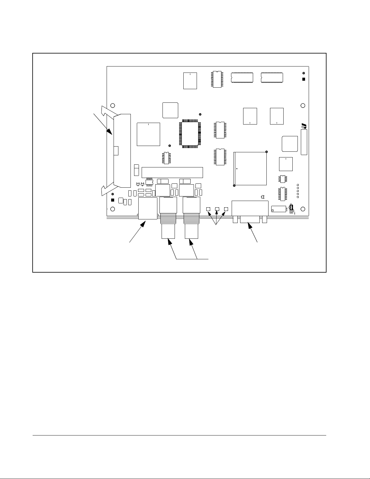
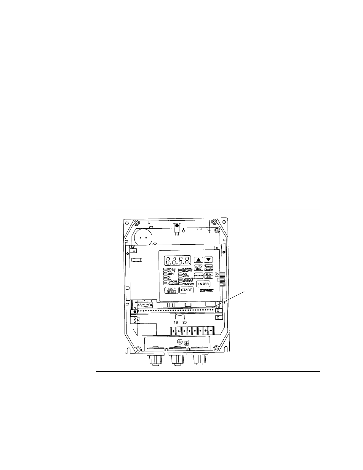
The ControlNet Network Communication Option Board makes the GV3000/SE drive a
node on the ControlNet network. It is a printed circuit board assembly that mounts
inside a GV3000/SE drive and connects to the drive’s Regulator board using a ribbon
cable. The Network Option board is powered from the standard drive power supply.
2CN3000). This board lets you operate and monitor a GV3000/SE
The Network Option board is equipped with flash memory that lets you easily update
the board with the latest firmware revisions without having to remove the board from
the drive. An RS-232C serial port lets you connect a serial programming device to the
Network Option board for updating the board’s flash memory.
The Network Option board connects to the ControlNet network using two BNC
connectors that provide for redundant communication. You can connect a
programming device for accessing nodes using the Network Access Port, which is an
RJ-45 connector.
Three LEDs provide information to you about the board. Refer to chapter 8 for
descriptions of how the LEDs function.
See figure 1.1 for the locations of the connectors and LEDs.
Introduction
1-1
Page 10
Ribbon Connector
to Regulator Board
ControlNet Network
Access Port
Figure 1.1 – ControlNet Network Communication Option Board
B
A
LEDs
RS-232 Connector
ControlNet Network Connectors
1-2
GV3000/SE AC Drive ControlNet Network Communication Option Board
Page 11

1.2 Where to Find Additional Information
You must be familiar with all the instruction manuals that describe your system
configuration. These manuals can include:
• GV3000/SE AC General Purpose (Volts/Hertz) and Vector Duty Drive Software
Start-Up and Reference Manual (D2-3359)
• GV3000/SE AC Drive Hardware Reference, Installation, and Troubleshooting
(D2-3360)
• GV3000/SE AC General Purpose (Volts/Hertz) and Vector Duty Bookshelf Drive
Software Start-Up and Reference Manual (D2-3426)
• GV3000/SE AC Bookshelf Drive Hardware Reference, Installation, and
Troubleshooting (D2-3427)
• ControlNet Network System Overview (1786-2.9)
• ControlNet Cable System Component List (AG-2.2)
• ControlNet Cable Planning and Installation Manual (1786-6.2.1)
• ControlNet Coax Tap Installation Manual (1786-5.7)
• ControlNet Network Access Cable Installation Instructions (1786-2.6)
• ControlNet Repeater Installation Instructions (1786-5.8)
You can obtain the ControlNet manuals listed above from The Automation Bookstore
at http://www.theautomationbookstore.com.
1.3 Getting Assistance from Reliance Electric
If you have any questions or problems with the products described in this instruction
manual, contact your local Reliance Electric sales office.
For technical assistance, call 1-864-284-5444. Before calling, please review the
troubleshooting section of this manual and check the standard drives website for
additional information. When you call this number, you will be asked for the drive
model number and this instruction manual number. Also, please have your product
version number ready.
Introduction
1-3
Page 12

1-4
GV3000/SE AC Drive ControlNet Network Communication Option Board
Page 13

CHAPTER 2
Installation
Contact Reliance if the drive installation must be in compliance with the European
Community Electromagnetic Compatibility Standards.
The ControlNet option board installation procedure differs depending on the drive
type. Use
table 2.1 to locate the appropriate procedure for your drive.
Table 2.1 – Locating the Appropriate Installation Procedure
Rating GV3000/SE Model Number Use the Procedure in Section …
1 HP 1V21xx
1V24xx
1 HP 1V41xx
1V44xx
2 HP 2V21xx
2V24xx
2 HP 2V41xx
2V44xx
3 HP 3V21xx
3V24xx
3 HP 3V41xx
3V44xx
5 HP 5V21xx
5V24xx
5 HP 5V41xx
5V44xx
7.5 HP 7V21xx
7V22xx
7.5 HP 7V41xx
7V42xx
2.3
2.1
2.3
2.1
2.3
2.1
2.3
2.1
2.3
2.2
Installation
10 HP 10V21xx
10V22xx
10 HP 10V41xx
10V42xx
15 HP 15V21xx
15V22xx
2.3
2.2
2.3
2-1
Page 14

Table 2.1 – Locating the Appropriate Installation Procedure
Rating GV3000/SE Model Number Use the Procedure in Section …
15 HP 15V41xx
2.5
15V42xx
20 HP 20V21xx
2.3
20V22xx
20 HP 20V41xx
2.5
20V42xx
25 HP 25G41xx
2.5
25G42xx
25V41xx
25V42xx
30 HP 30V20xx 2.4
30 HP 30V41xx
2.5
30V42xx
40 HP 40V20xx 2.4
40 HP 40V41xx
2.5
40V42xx
50 HP 50R41xx 2.6
50 HP 50T41xx 2.6
50 HP 50V20xx 2.4
50 HP 50V41xx
2.5
50V42xx
60 HP 60G41xx
2.5
60G42xx
60 HP 60V20xx 2.4
75 HP 75R41xx 2.6
75 HP 75T41xx 2.6
75 HP 75V20xx 2.4
75 HP 75V40xx 2.4
100 HP 100V20xx 2.4
100 HP 100V40xx 2.4
125 HP 125R41xx 2.6
125 HP 125V40xx 2.4
150 HP 150V40xx 2.4
200 HP 200V40xx 2.4
2-2
GV3000/SE AC Drive ControlNet Network Communication Option Board
Page 15

Table 2.1 – Locating the Appropriate Installation Procedure
Rating GV3000/SE Model Number Use the Procedure in Section …
200 HP 200V41xx 2.7
250 HP 250V41xx 2.7
300 HP 300V41xx 2.7
350 HP 350V41xx 2.7
400 HP 400V41xx 2.7
2 to 15 Amp 31ER40xx
31ET40xx
38ER40xx
38ET40xx
55ER40xx
55ET40xx
85ER40xx
85ET40xx
126ER40xx
126ET40xx
150ER40xx
150ET40xx
24 to 30 Amp 240ER40xx
240ET40xx
300ER40xx
300ET40xx
43 Amp 430ER40xx
430ET40xx
2.8
2.8
2.8
Installation
2-3
Page 16
2.1 Installing the ControlNet Option Board in
1 to 5 HP @ 460 VAC Drives
ATTENTION:Only qualified electrical personnel familiar with the
construction and operation of this equipment and the hazards involved
!
should install, adjust, operate, or service this equipment. Read and
understand this manual and other applicable manuals in their entirety
before proceeding. Failure to observe this precaution could result in
severe bodily injury or loss of life.
ATTENTION:The drive is at line voltage when connected to incoming
AC power. Disconnect, lock out, and tag all incoming power to the drive
before performing the following procedure. Failure to observe this
precaution could result in severe bodily injury or loss of life.
ATTENTION:DC bus capacitors retain hazardous voltages after input
power has been disconnected. After disconnecting input power, wait five
minutes for the DC bus capacitors to discharge and then check the
voltage with a voltmeter to ensure the DC bus capacitors are discharged
before touching any internal components. Failure to observe this
precaution could result in severe bodily injury or loss of life.
ATTENTION:The drive contains ESD- (Electrostatic Discharge)
sensitive parts and assemblies. Static control precautions are required
when installing, testing, servicing, or repairing the drive. Erratic machine
operation and damage to, or destruction of, equipment can result if this
procedure is not followed. Failure to observe this precaution can result
in bodily injury.
Use this procedure to install the ControlNet option board in the drives listed in
table 2.2.
Table 2.2 – Model Numbers for 1 to 5 HP @ 460 VAC Drives
1V41xx
1V44xx
2V41xx
2V44xx
If the drive is panel-mounted, this procedure will be easier to perform if the drive is
removed from the panel.
Unless otherwise indicated, keep all hardware that is removed. You will need it for
reassembly. This includes screws, lock washers, and rivets.
Important: Read and understand the warning labels on the outside of the drive
before proceeding.
3V41xx
3V44xx
5V41xx
5V44xx
2-4
GV3000/SE AC Drive ControlNet Network Communication Option Board
Page 17
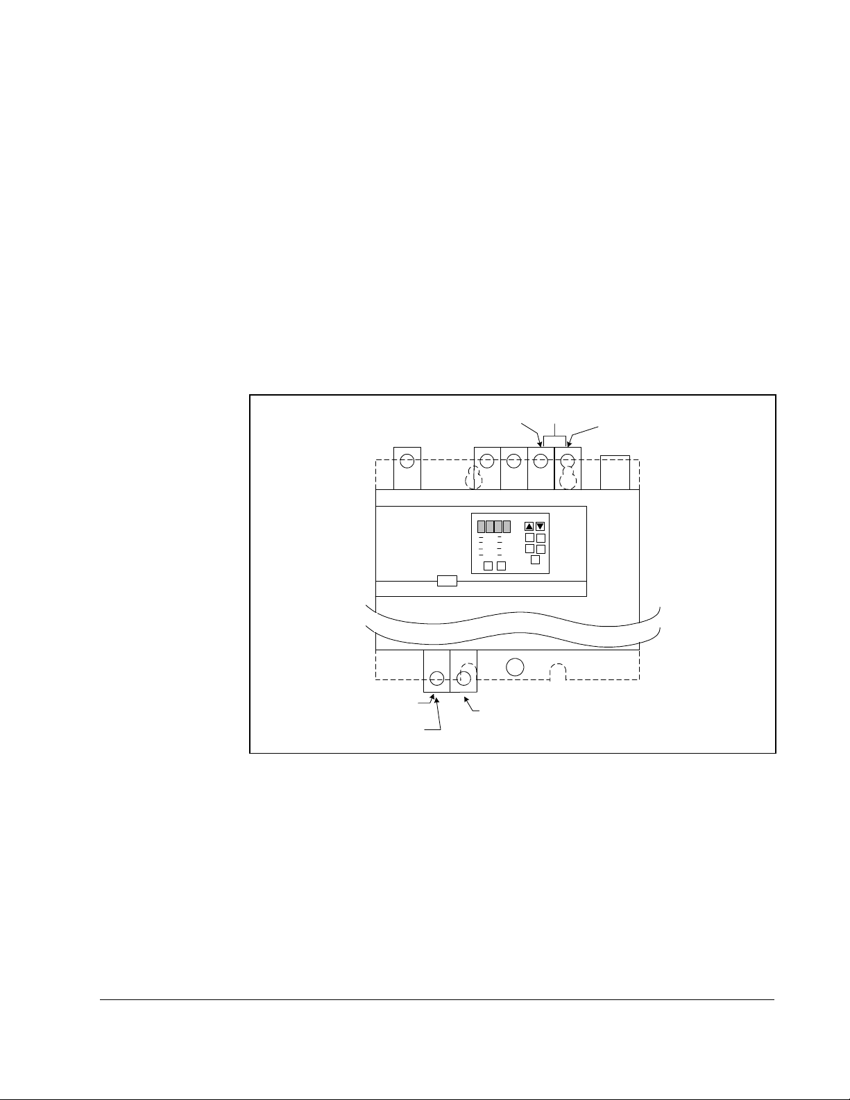
Step 1. Shut Down the Drive
Step 1.1 Disconnect, lock out, and tag all incoming power to the drive.
Step 1.2 Wait five minutes for the DC bus capacitors to discharge.
Step 1.3 Remove the cover by loosening the four cover screws.
Important: Read and understand the warning labels on the inside of the drive before
proceeding.
Step 2. Verify that the DC Bus Capacitors are Discharged
Step 2.1 Use a voltmeter to verify that there is no voltage at the drive’s AC input
power terminals (R/L1, S/L2, T/L3).
Step 2.2 Ensure that the DC bus capacitors are discharged. To check
bus potential:
DC
a. Stand on a non-conductive surface and wear insulated gloves.
b. Use a voltmeter to measure the DC bus potential at the DC bus power
terminals as shown in
figure 2.1.
R/L1 T/L3
S/L2 1 0V 10 CO M
AC Power
Input Leads
Figure 2.1 – DC Bus Voltage Terminals (1 to 5 HP @ 460 VAC)
+
–+
DC Bus
Volts
Step 3. Remove the Keypad Bracket from the Drive
Step 3.1 Record connections to the Regulator board terminal strip if they must be
disconnected to remove the keypad bracket.
Step 3.2 Use a magnetic screwdriver to remove the three M4 x 10 screws that fasten
the bottom of the keypad support bracket to the drive heat sink.
Important: The keypad support bracket is connected to the drive by wiring. Do not lift
the bracket completely out of the drive to prevent damage to wiring.
Step 3.3 Spread the retaining clips on the 26-conductor Regulator board ribbon
cable connector to disconnect it from the Current Feedback board. The
Current Feedback board is located on the right below the keypad.
Step 3.4 Move the keypad support bracket aside.
–
W/T3V/T2U/T1
Motor Leads
Installation
Step 3.5 Pinch the retaining clip that is through the center of the Current Feedback
board and carefully pull out the Current Feedback board.
Step 3.6 Unplug the internal fan assembly power connector (CONN7) from the drive.
2-5
Page 18
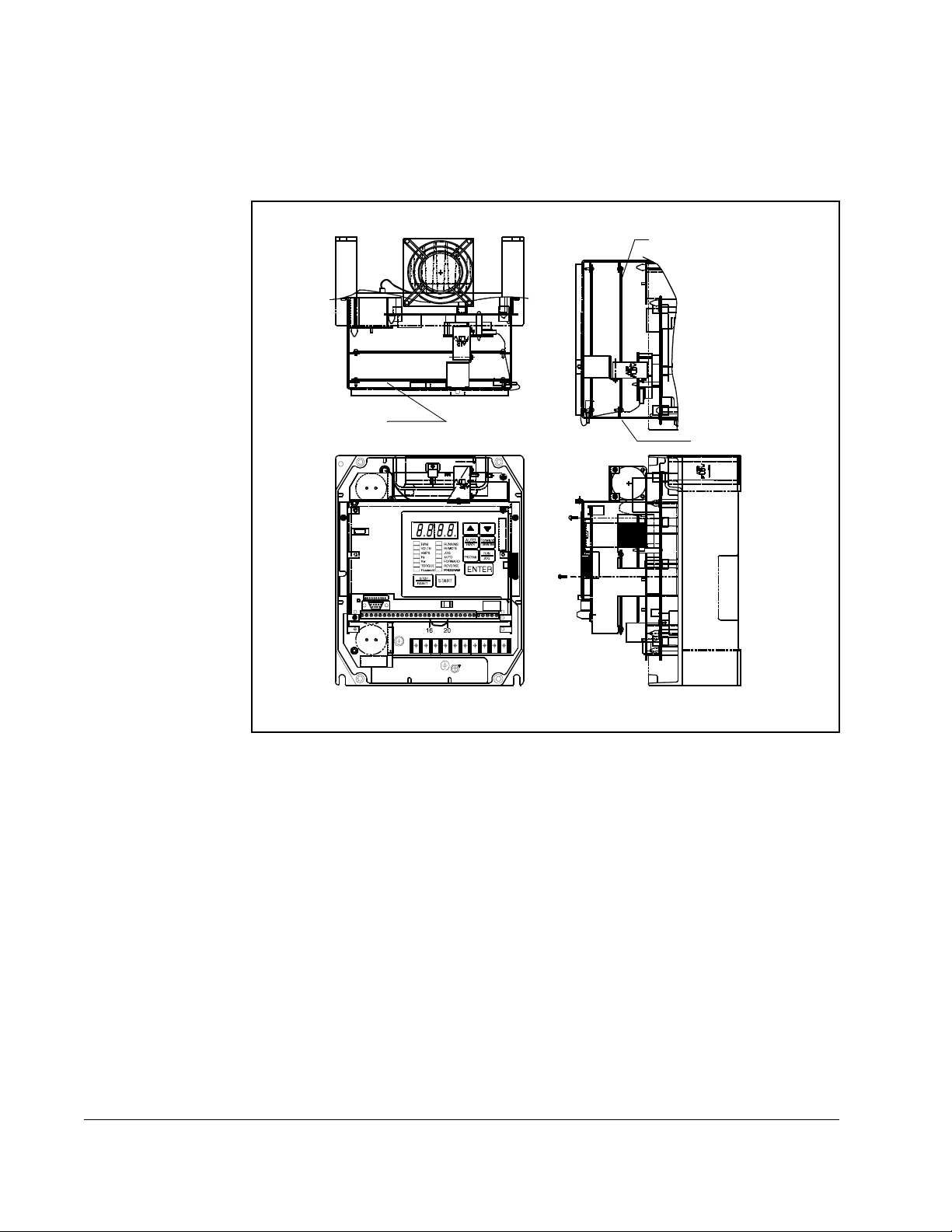
Step 4. Install the ControlNet Option Board in the Keypad Bracket
Refer to figure 2.2 for component locations.
Regulator Board
To p Vi ew
ControlNet Option
Board
Current Feedback
Board
2-6
Front View
Figure 2.2 – 1 to 5 HP @ 460 VAC GV3000/SE Drive
Side View
Step 4.1 Remove the ControlNet option board from its anti-static wrapper.
Step 4.2 Align the key on the connector of the ControlNet option board ribbon cable
with the key on the Regulator board connector. Press the ribbon cable
connector in until it locks into position.
Step 4.3 Route the 26-conductor ribbon cable for the Current Feedback board out of
the side of the keypad bracket.
Step 4.4 Align the ControlNet option board on the four mounting tabs on the keypad
bracket. Make sure that the ribbon cable is not pinched between the keypad
bracket and the ControlNet option board.
Step 4.5 Fasten the right side of the ControlNet option board to the keypad bracket.
Use the two metal M3 screws and lock washers for grounding.
Important: You must use the lock washers to properly ground the option board.
Improper grounding of the option board can result in erratic operation of
the drive.
GV3000/SE AC Drive ControlNet Network Communication Option Board
Page 19
Step 4.6 Fasten the left side of the ControlNet option board to the keypad bracket
using the two plastic rivets.
Step 5. Reinstall the Keypad Bracket in the Drive
Step 5.1 Reconnect the internal fan assembly power connector (CONN7) to the
drive. Align the key on the connector with the slot in the receptacle. Press
the connector into position.
ATTENTION:Proper alignment of the Current Feedback board is critical.
Verify that the connector pins on the Current Feedback board are
!
Step 5.2 Reinstall the Current Feedback board. Carefully align the two sets of
Step 5.3 Inspect the Current Feedback board connector thoroughly for bent or
Step 5.4 Align the keypad support bracket with the mounting holes in the drive heat
correctly aligned with their corresponding con nectors on the drive. Failure
to observe this precaution can result in bodily injury.
connector pins on the Current Feedback board with their matching
connectors on the drive. Gently press the board into place. The board
should go in easily. If you feel resistance, a pin might be bent or misaligned.
Recheck alignment and retry installation.
misaligned pins.
sink. Fasten the bracket with the three M4 x 10 screws removed earlier.
Step 5.5 Align the Regulator board’s 26-conductor ribbon cable connector with the
Current Feedback board connector. Press it in until it locks into position.
Step 5.6 Route the Network Drop Cable through the left-most opening at the bottom
of the drive.
Step 5.7 Connect the brown wire to terminal 1 of the 2-connector terminal strip.
Connect the white wire to terminal 2.
Step 5.8 Reconnect any wiring that was removed from the Regulator board.
Step 5.9 NEMA 4X/12 drives only: Before installing the cover, check that the gaskets
on the cover are flat and within the gasket channels.
Step 5.10 Reinstall the cover. Align all cover screws into the heat sink before
tightening any of them.
To maintain the integrity of NEMA 4X/12 drives, sequentially tighten the
cover screws to ensure even compression of the gaskets. Do not exceed
Nm (20 in-lb) of torque on these screws.
2.2
This completes the hardware installation of the ControlNet option board. Do not
remove the lockout and tag until you have completed
instruction on connecting to the ControlNet network.
section 2.9, which provides
Installation
2-7
Page 20

2.2 Installing the ControlNet Option Board in
7.5 to 10 HP @ 460 VAC Drives
ATTENTION:Only qualified electrical personnel familiar with the
construction and operation of this equipment and the hazards involved
!
should install, adjust, operate, or service this equipment. Read and
understand this manual and other applicable manuals in their entirety
before proceeding. Failure to observe this precaution could result in
severe bodily injury or loss of life.
ATTENTION:The drive is at line voltage when connected to incoming
AC power. Disconnect, lock out, and tag all incoming power to the drive
before performing the following procedure. Failure to observe this
precaution could result in severe bodily injury or loss of life.
ATTENTION:DC bus capacitors retain hazardous voltages after input
power has been disconnected. After disconnecting input power, wait five
minutes for the DC bus capacitors to discharge and then check the
voltage with a voltmeter to ensure the DC bus capacitors are discharged
before touching any internal components. Failure to observe this
precaution could result in severe bodily injury or loss of life.
ATTENTION:The drive contains ESD- (Electrostatic Discharge)
sensitive parts and assemblies. Static control precautions are required
when installing, testing, servicing, or repairing the drive. Erratic machine
operation and damage to, or destruction of, equipment can result if this
procedure is not followed. Failure to observe this precaution can result
in bodily injury.
Use this procedure to install the ControlNet option board in drives with model numbers
7V41xx, 7V42xx, 10V41xx, or 10V42xx.
If the drive is panel-mounted, this procedure will be easier to perform if the drive is
removed from the panel.
Unless otherwise indicated, keep all hardware that is removed. You will need it for
reassembly. This includes screws, lock washers, and rivets.
Important: Read and understand the warning labels on the outside of the drive
before proceeding.
Step 1. Shut Down the Drive
Step 1.1 Disconnect, lock out, and tag all incoming power to the drive.
Step 1.2 Wait five minutes for the DC bus capacitors to discharge.
Step 1.3 Remove the cover by loosening the four cover screws.
Important: Read and understand the warning labels on the inside of the drive before
proceeding.
2-8
GV3000/SE AC Drive ControlNet Network Communication Option Board
Page 21
Step 2. Verify that the DC Bus Capacitors are Discharged
Step 2.1 Use a voltmeter to verify that there is no voltage at the drive’s AC input
power terminals (R/L1, S/L2, T/L3).
Step 2.2 Ensure that the DC bus capacitors are discharged. To check
DC bus potential:
a. Stand on a non-conductive surface and wear insulated gloves.
b. Use a voltmeter to measure the DC bus potential at the DC bus power
terminals shown in
figure 2.3.
R/L1 T/L3
S/L2 10V 10 CO M
AC Power
Input Leads
Figure 2.3 – DC Bus Voltage Terminals (7.5 to 10 HP)
+
–+
DC Bus
Volts
Step 3. Remove the Keypad Bracket from the Drive
Step 3.1 Record connections to the Regulator board terminal strip if they must be
disconnected to remove the keypad bracket.
Step 3.2 Loosen the thumb screw on the left side of the keypad bracket. Hold the
bracket on the left and lift the bracket up and to the left to separate it from
the keypad support bracket.
Important: The bracket is connected to the drive by wiring. Do not attempt to lift the
bracket out completely as this can damage or pull out wiring. Tie up or
support the bracket to prevent damage to the wiring.
Step 3.3 Spread the retaining clips on the 26-conductor Regulator board ribbon
cable connector to disconnect it from the Current Feedback board. The
Current Feedback board is located on the right below the keypad.
–
W/T3V/T2U/T1
Motor Leads
Installation
2-9
Page 22
Step 4. Install the ControlNet Option Board in the Keypad Bracket
Refer to figure 2.4 for component locations.
Top Vi ew
Current Feedback Board
Regulator Board
Front View
Figure 2.4 – 7.5 to 10 HP @ 460 VAC GV3000/SE Drive
Network Option Board
Side View
Step 4.1 Remove the ControlNet option board from its anti-static wrapper.
Step 4.2 Align the key on the connector of the ControlNet option board ribbon cable
with the key on the Regulator board connector. Press the ribbon cable
connector in until it locks into position.
2-10
Step 4.3 Route the 26-conductor ribbon cable for the Current Feedback board out of
the side of the keypad bracket.
Step 4.4 Align the ControlNet option board on the four mounting tabs on the keypad
bracket. Make sure that the ribbon cable is not pinched between the keypad
bracket and the ControlNet option board.
Step 4.5 Fasten the right side of the ControlNet option board to the keypad bracket.
Use the two metal M3 screws and lock washers for grounding.
Important: You must use the lock washers to properly ground the option board.
Improper grounding of the option board can result in erratic operation of
the drive.
GV3000/SE AC Drive ControlNet Network Communication Option Board
Page 23

Step 4.6 Fasten the left side of the ControlNet option board to the keypad bracket
using the two plastic rivets.
Step 4.7 Reconnect the keypad bracket to the keypad support bracket by inserting
the mounting tabs into the slots in the support bracket and tightening the
thumb screw.
Step 4.8 Align the Regulator board’s 26-conductor ribbon cable connector with the
Current Feedback board connector. Press it in until it locks into position.
Step 5. Reinstall the Keypad Support Bracket in the Drive
Step 5.1 Route the Network Drop Cable through the left-most opening at the bottom
of the drive.
Step 5.2 Connect the brown wire to terminal 1 of the 2-connector terminal strip.
Connect the white wire to terminal 2.
Step 5.3 Reconnect any wiring that was removed from the Regulator board.
Step 5.4 NEMA 4X/12 drives only: Before installing the cover, check that the gaskets
on the cover are flat and within the gasket channels.
Step 5.5 Reinstall the cover. Align all cover screws into the heat sink before
tightening any of them.
To maintain the integrity of NEMA 4X/12 drives, sequentially tighten the
cover screws to ensure even compression of the gaskets. Do not exceed
2.2 Nm (20 in-lb) of torque on these screws.
This completes the hardware installation of the ControlNet option board. Do not
remove the lockout and tag until you have completed section 2.9, which provides
instruction on connecting to the ControlNet network.
Installation
2-11
Page 24
2.3 Installing the ControlNet Option Board in
1 to 20 HP @ 230 VAC Drives
ATTENTION:Only qualified electrical personnel familiar with the
construction and operation of this equipment and the hazards involved
!
should install, adjust, operate, or service this equipment. Read and
understand this manual and other applicable manuals in their entirety
before proceeding. Failure to observe this precaution could result in
severe bodily injury or loss of life.
ATTENTION:The drive is at line voltage when connected to incoming
AC power. Disconnect, lock out, and tag all incoming power to the drive
before performing the following procedure. Failure to observe this
precaution could result in severe bodily injury or loss of life.
ATTENTION:DC bus capacitors retain hazardous voltages after input
power has been disconnected. After disconnecting input power, wait five
minutes for the DC bus capacitors to discharge and then check the
voltage with a voltmeter to ensure the DC bus capacitors are discharged
before touching any internal components. Failure to observe this
precaution could result in severe bodily injury or loss of life.
ATTENTION:The drive contains ESD- (Electrostatic Discharge)
sensitive parts and assemblies. Static control precautions are required
when installing, testing, servicing, or repairing the drive. Erratic machine
operation and damage to, or destruction of, equipment can result if this
procedure is not followed. Failure to observe this precaution can result
in bodily injury.
Use this procedure to install the ControlNet option board in the drives listed in
table 2.3.
Table 2.3 – Model Numbers for 1 to 20 HP @230 VAC Drives
1V21xx
1V24xx
2V21xx
2V24xx
3V21xx
3V24xx
5V21xx
5V24xx
If the drive is panel-mounted, this procedure will be easier to perform if the drive is
removed from the panel.
Unless otherwise indicated, keep all hardware that is removed. You will need it for
reassembly. This includes screws, lock washers, and rivets.
Important: Read and understand the warning labels on the outside of the drive
before proceeding.
7V21xx
7V22xx
10V21xx
10V22xx
15V21xx
15V22xx
20V21xx
20V22xx
2-12
GV3000/SE AC Drive ControlNet Network Communication Option Board
Page 25

Step 1. Shut Down the Drive
Step 1.1 Disconnect, lock out, and tag all incoming power to the drive.
Step 1.2 Wait five minutes for the DC bus capacitors to discharge.
Step 1.3 Remove the cover by loosening the four cover screws.
Important: Read and understand the warning labels on the inside of the drive before
proceeding.
Step 2. Verify that the DC Bus Capacitors are Discharged
Step 2.1 Use a voltmeter to verify that there is no voltage at the drive’s AC input
power terminals (R/L1, S/L2, T/L3).
Step 2.2 Ensure that the DC bus capacitors are discharged. To check
DC bus potential:
a. Stand on a non-conductive surface and wear insulated gloves.
b. Use a voltmeter to measure the DC bus potential at the DC bus power
terminals shown in
figure 2.5.
R/L1 T/L3
S/L2 1 0V 10 CO M
AC Power
Input Leads
Figure 2.5 – DC Bus Voltage Terminals (1 to 20 HP @ 230 VAC)
+
–+
DC Bus
Volts
Step 3. Remove the Keypad Bracket from the Drive
Step 3.1 Record connections to the Regulator board terminal strip if they must be
disconnected to remove the keypad bracket.
Step 3.2 Use a magnetic screwdriver to remove the M4 x 10 screws that fasten the
bottom of the keypad support bracket to the drive heat sink.
Step 3.3 Spread the retaining clips on the Regulator board ribbon cable (on the right
side) to disconnect it from the Base Board.
Step 3.4 Remove the keypad bracket. Place it with the keypad down on a flat
surface. If you cannot lay it flat, tie it up to prevent damage to wiring.
–
W/T3V/T2U/T1
Motor Leads
Installation
2-13
Page 26
Step 4. Install the ControlNet Option Board in the Keypad Bracket
Refer to figure 2.6 for component locations.
Step 4.1 Remove the ControlNet option board from its anti-static wrapper.
Step 4.2 Align the key on the connector of the ControlNet option board ribbon cable
with the key on the Regulator board connector. Press the ribbon cable
connector in until it locks into position.
Step 4.3 Route the other ribbon cable out of the side of the keypad bracket.
Step 4.4 Align the ControlNet option board on the four mounting tabs on the keypad
bracket. Make sure that the ribbon cable is not pinched between the keypad
bracket and the ControlNet option board.
Step 4.5 Fasten the right side of the ControlNet option board to the keypad bracket.
Use the two metal M3 screws and lock washers for grounding.
Important: You must use the lock washers to properly ground the option board.
Improper grounding of the option board can result in erratic operation of
the drive.
Step 4.6 Fasten the left side of the ControlNet option board to the keypad bracket
using the two plastic rivets.
Keypad Bracket
Regulator Board
Te rm in al St ri p
Power Terminal
Strip
Figure 2.6 – 1 to 20 HP @ 230 VAC GV3000/SE Drive
2-14
GV3000/SE AC Drive ControlNet Network Communication Option Board
Page 27

Step 5. Reinstall the Keypad Bracket in the Drive
Step 5.1 Place the keypad support bracket back into position. Use a magnetic
screwdriver to fasten it to the heatsink with the screws removed earlier.
Step 5.2 Realign the 26-conductor ribbon cable connector with the connector inside
the slot in the keypad support bracket. Carefully press the ribbon cable
connector in until the retaining clips lock into place.
Step 5.3 Route the Network Drop Cable through the left-most opening at the bottom
of the drive.
Step 5.4 Connect the brown wire to terminal 1 of the 2-connector terminal strip.
Connect the white wire to terminal 2.
Step 5.5 Reconnect any wiring that was removed from the Regulator board.
Step 5.6 NEMA 4X/12 drives only: Before installing the cover, check that the gaskets
on the cover are flat and within the gasket channels.
Step 5.7 Reinstall the cover. Align all cover screws into the heat sink before
tightening any of them.
To maintain the integrity of NEMA 4X/12 drives, sequentially tighten the
cover screws to ensure even compression of the gaskets. Do not exceed
2.2 Nm (20 in-lb) of torque on these screws.
This completes the hardware installation of the ControlNet option board. Do not
remove the lockout and tag until you have completed section 2.9, which provides
instruction on connecting to the ControlNet network.
Installation
2-15
Page 28
2.4 Installing the ControlNet Option Board in
30 to 100 HP @ 230 VAC and 75 to 200 HP@460 VAC
Drives
ATTENTION:Only qualified electrical personnel familiar with the
construction and operation of this equipment and the hazards involved
!
should install, adjust, operate, or service this equipment. Read and
understand this manual and other applicable manuals in their entirety
before proceeding. Failure to observe this precaution could result in
severe bodily injury or loss of life.
ATTENTION:The drive is at line voltage when connected to incoming
AC power. Disconnect, lock out, and tag all incoming power to the drive
before performing the following procedure. Failure to observe this
precaution could result in severe bodily injury or loss of life.
ATTENTION:DC bus capacitors retain hazardous voltages after input
power has been disconnected. After disconnecting input power, wait five
minutes for the DC bus capacitors to discharge and then check the
voltage with a voltmeter to ensure the DC bus capacitors are discharged
before touching any internal components. Failure to observe this
precaution could result in severe bodily injury or loss of life.
ATTENTION:The drive contains ESD- (Electrostatic Discharge)
sensitive parts and assemblies. Static control precautions are required
when installing, testing, servicing, or repairing the drive. Erratic machine
operation and damage to, or destruction of, equipment can result if this
procedure is not followed. Failure to observe this precaution can result
in bodily injury.
Use this procedure to install the ControlNet option board in the drives listed in
table 2.4.
Table 2.4 – Model Numbers for 30 to 100 HP @ 230 VAC and 75 to 200 HP@460 VAC Drives
30V20xx 100V20xx
40V20xx 100V40xx
50V20xx 125V40xx
60V20xx 150V40xx
75V20xx 200V40xx
75V40xx
Unless otherwise indicated, keep all hardware that is removed. You will need it for
reassembly. This includes screws, lock washers, and rivets.
Important: Read and understand the warning labels on the outside of the drive
before proceeding.
2-16
GV3000/SE AC Drive ControlNet Network Communication Option Board
Page 29
Step 1. Shut Down the Drive
Step 1.1 Disconnect, lock out, and tag all incoming power to the drive.
Step 1.2 Wait five minutes for the DC bus capacitors to discharge.
Step 2. Verify that the DC Bus Capacitors are Discharged
Step 2.1 Use a voltmeter to verify that there is no voltage at the drive’s AC input
power terminals (R/L1, S/L2, T/L3).
Step 2.2 Ensure that the DC bus capacitors are discharged. To check
DC bus potential:
a. Stand on a non-conductive surface and wear insulated gloves.
b. Use a voltmeter to measure the DC bus potential at the DC bus power
terminals shown in
R
figure 2.7.
S
P (+)
DC Bus
Volts
T
N (-)
Installation
U (T1)
W (T3)
Figure 2.7 – DC Bus Voltage Terminals (30 to 100 HP @ 230 VAC and 75 to 200 HP @ 460 VAC Drives)
GND
V (T2)
Step 3. Remove the Keypad Bracket from the Drive
Step 3.1 If the drive has:
• A Regulator board cover and terminal cover: Remove the three M4
screws from the Regulator board cover. Remove the cover. See
figure 2.8.
• A terminal cover only: If you have this type of drive, this procedure is
easier to perform if you lay the drive on its side. Remove the side cover
from the drive. Use a long magnetized screwdriver to unfasten the four
screws that hold the keypad bracket in.
2-17
Page 30
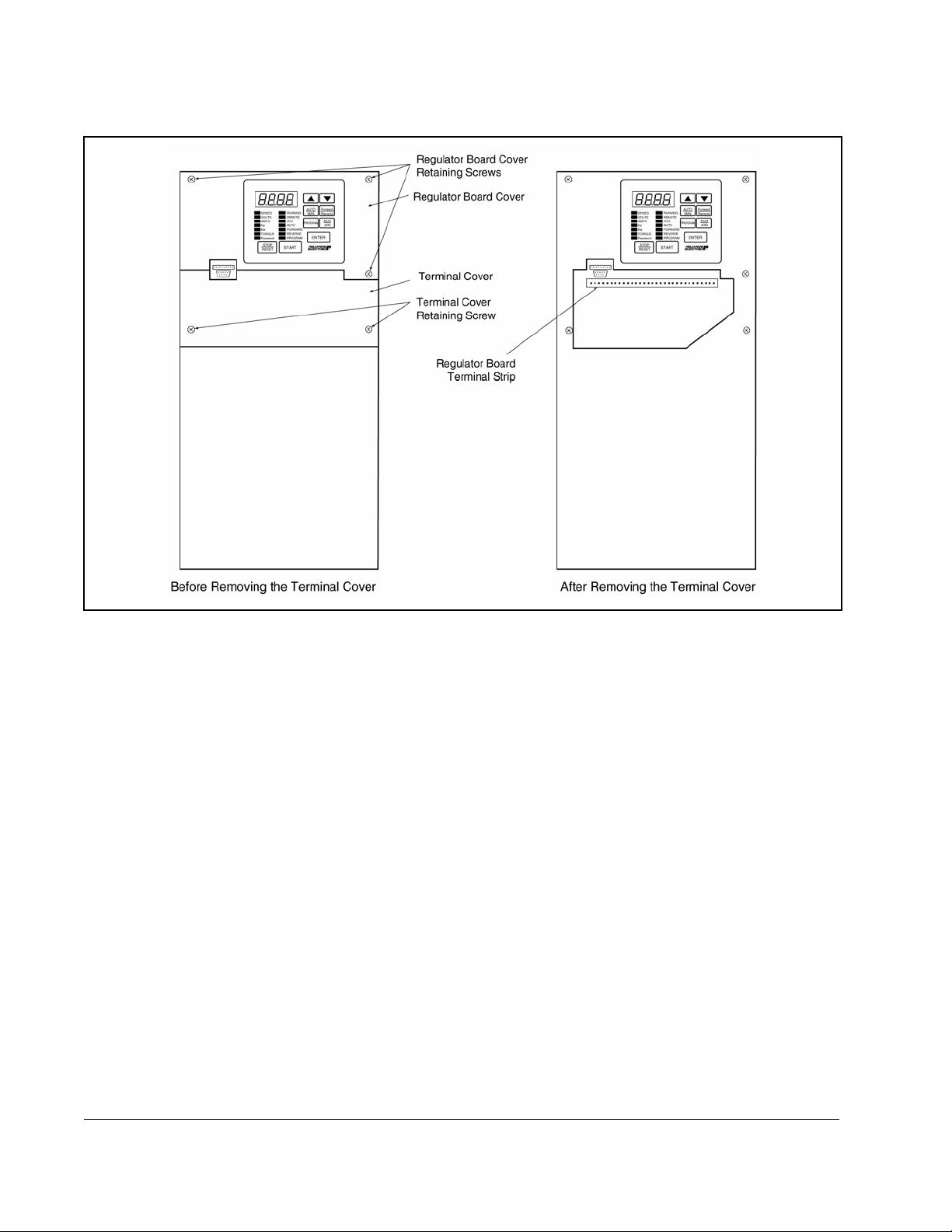
Figure 2.8 – Location of Terminal Cover and Regulator Board Cover in 75 to 200 HP (460 VAC) and 30 to 100 HP (230 VAC) Drives
Step 3.2 Record connections to the Regulator board terminal strip if they must be
disconnected to remove the keypad bracket.
Step 3.3 Remove the terminal cover, which is below the keypad and fastened with
two M4 screws. See
figure 2.8.
Step 3.4 Pull the keypad assembly partly out of the drive. Spread the retaining clips
on the Regulator board ribbon cable (on the right side) to disconnect it from
the Base Board. See
figure 2.9.
Step 3.5 Remove the keypad bracket. Place it with the keypad down on a flat
surface. If you cannot lay it flat, tie it up to prevent damage to wiring.
2-18
GV3000/SE AC Drive ControlNet Network Communication Option Board
Page 31

Front
Regulator Board
Ribbon Cable
Connecting
Regulator Board and
Base Board
Metal Screw
Ribbon Cable
Connector to
Connect Base
Board
Ribbon Cable
Connector to
Connect Keypad
Plastic Rivet
To p V iew
Back Side of
Regulator Board
Network
Option Board
Rear View of Regulator Board
Ribbon Cable
Connecting
Regulator Board and
Option Board
To Base Board
Insulator
Ribbon Cable
Connector to
Connect Option
Board
Terminal Strip
Installation
Figure 2.9 – Regulator Board’s Connections to Option Board, Keypad, and Base Board
Step 4. Install the ControlNet Option Board in the Keypad Bracket
Refer to figures 2.8 and 2.9.
Step 4.1 Remove the ControlNet option board from its anti-static wrapper.
Step 4.2 Align the key on the connector of the ControlNet option board ribbon cable
with the key on the Regulator board connector. Press the ribbon cable
connector in until it locks into position.
Step 4.3 Route the other ribbon cable out of the side of the keypad bracket.
Step 4.4 Align the ControlNet option board on the four mounting tabs on the keypad
bracket. Make sure that the ribbon cable is not pinched between the keypad
bracket and the ControlNet option board.
Step 4.5 Fasten the right side of the ControlNet option board to the keypad bracket.
Use the two metal M3 screws and lock washers for grounding.
Important: You must use the lock washers to properly ground the option board.
Improper grounding of the option board can result in erratic operation of
the drive.
2-19
Page 32

Step 4.6 Fasten the left side of the ControlNet option board to the keypad bracket
using the two plastic rivets.
Step 5. Reinstall the Keypad Bracket in the Drive
Step 5.1 Align the Regulator board ribbon cable connector with the connector to the
Base board. Carefully press the ribbon cable connector in until the retaining
clips lock into place.
Step 5.2 Place the keypad bracket back into position.
Step 5.3 If the drive has:
• A Regulator board cover and terminal cover: Replace the Regulator board
cover. Fasten it using the three M4 screws removed earlier.
• Only a terminal cover: Use a long magnetized screwdriver to fasten the
four screws that hold the keypad bracket. Replace the side cover on the
drive.
Step 5.4 Route the Network Drop Cable through the left-most opening at the bottom
of the drive.
Step 5.5 Connect the brown wire to terminal 1 of the 2-connector terminal strip.
Connect the white wire to terminal 2.
Step 5.6 Reconnect any wiring that was removed from the Regulator board.
Step 5.7 Replace the terminal cover (below the keypad). Fasten it using the two M4
screws removed earlier.
This completes the hardware installation of the ControlNet option board. Do not
remove the lockout and tag until you have completed section 2.9, which provides
instruction on connecting to the ControlNet network.
2-20
GV3000/SE AC Drive ControlNet Network Communication Option Board
Page 33

2.5 Installing the ControlNet Option Board in 15 to 25 HP
and 25 to 60 HP @ 460 VAC Drives
ATTENTION:Only qualified electrical personnel familiar with the
construction and operation of this equipment and the hazards involved
!
should install, adjust, operate, or service this equipment. Read and
understand this manual and other applicable manuals in their entirety
before proceeding. Failure to observe this precaution could result in
severe bodily injury or loss of life.
ATTENTION:The drive is at line voltage when connected to incoming
AC power. Disconnect, lock out, and tag all incoming power to the drive
before performing the following procedure. Failure to observe this
precaution could result in severe bodily injury or loss of life.
ATTENTION:DC bus capacitors retain hazardous voltages after input
power has been disconnected. After disconnecting input power, wait five
minutes for the DC bus capacitors to discharge and then check the
voltage with a voltmeter to ensure the DC bus capacitors are discharged
before touching any internal components. Failure to observe this
precaution could result in severe bodily injury or loss of life.
ATTENTION:The drive contains ESD- (Electrostatic Discharge)
sensitive parts and assemblies. Static control precautions are required
when installing, testing, servicing, or repairing the drive. Erratic machine
operation and damage to, or destruction of, equipment can result if this
procedure is not followed. Failure to observe this precaution can result
in bodily injury.
Use this procedure to install the ControlNet option board in drives with the model
numbers listed in
Unless otherwise indicated, keep all hardware that is removed. You will need it for
reassembly. This includes screws, lock washers, and rivets.
If the drive is panel-mounted, this procedure will be easier to perform if the drive is
removed from the panel.
Important: Read and understand the warning labels on the outside of the drive
table 2.5.
Table 2.5 – Model Numbers for 15 to 60 HP @460 VAC Drives
15V41xx
15V42xx
20V41xx
20V42xx
25G41xx
25G42xx
25V41xx
25V42xx
before proceeding.
30V41xx
30V42xx
40V41xx
40V42xx
50V41xx
50V42xx
60G41xx
60G42xx
Installation
2-21
Page 34

Step 1. Shut Down the Drive
Step 1.1 Disconnect, lock out, and tag all incoming power to the drive.
Step 1.2 Wait five minutes for the DC bus capacitors to discharge.
Step 1.3 Remove the cover by loosening the four cover screws.
Important: Read and understand the warning labels on the inside of the drive before
proceeding.
Step 2. Verify that the DC Bus Capacitors are Discharged
Step 2.1 Use a voltmeter to verify that there is no voltage at the drive’s AC input
power terminals (R/L1, S/L2, T/L3).
Step 2.2 Ensure that the DC bus capacitors are discharged. To check
DC bus potential:
a. Stand on a non-conductive surface and wear insulated gloves.
b. Use a voltmeter to measure the DC bus potential at the DC bus power
terminals as shown in figures
2.10 (15 to 25 HP) and 2.11 (25 to 60 HP).
U/T1 T/L3
V/T2
Motor Leads
Figure 2.10 – DC Bus Voltage Terminals (15 to 25 HP @ 460 VAC)
+
DC Bus
Volts
–
R/L1W/T3
S/L2
AC Power
Input Leads
2-22
GV3000/SE AC Drive ControlNet Network Communication Option Board
Page 35

DC Bus Volts
Input Wiring
+
–
Figure 2.11 – DC Bus Voltage Terminals (25 to 60 HP @ 460 VAC)
Step 3. Remove the Keypad Bracket from the Drive
Step 3.1 Record connections to the Regulator board terminal strip if they must be
disconnected to remove the keypad bracket.
Step 3.2 Loosen the thumb screw on the left side of the keypad bracket. Hold the
bracket on the left and lift the bracket up and to the left to separate it from
the keypad support bracket.
Important: The bracket is connected to the drive by wiring. Do not attempt to lift the
bracket out completely as this can damage or pull out wiring. Tie up or
support the bracket to prevent damage to the wiring.
Step 3.3 Disconnect the 26-conductor Regulator board ribbon cable from the Power
Supply board (located on the right side below the keypad). You can see the
connector through the slot on the keypad support bracket. Use a small
screwdriver inserted through the slot to spread the retaining clips on the
connector to release it.
R/L1
S/L2
T/L3
Installation
2-23
Page 36

Top Vi ew
Top View
Network Option Board
Regulator Board
Regulator Board
Front View
15 to 25 HP @ 460 VAC
25 to 60 HP @ 460 VAC
Figure 2.12 – GV3000/SE Drive (15 to 25 and 25 to 60 HP @ 460 VAC)
Step 4. Install the ControlNet Option Board in the Keypad Bracket
Refer to figure 2.12 for component locations.
Step 4.1 Remove the ControlNet option board from its anti-static wrapper.
Step 4.2 Align the key on the connector of the ControlNet option board ribbon cable
with the key on the Regulator board connector. Press the ribbon cable
connector in until it locks into position.
Network Option Board
Front View
2-24
Step 4.3 Align the ControlNet option board on the four mounting tabs on the keypad
bracket. Make sure that the ribbon cable is not pinched between the keypad
bracket and the ControlNet option board.
Step 4.4 Fasten the right side of the ControlNet option board to the keypad bracket.
Use the two metal M3 screws and lock washers for grounding.
Important: You must use the lock washers to properly ground the option board.
Improper grounding of the option board can result in erratic operation of
the drive.
Step 4.5 Fasten the left side of the ControlNet option board to the keypad bracket
using the two plastic rivets.
Step 4.6 Realign the 26-conductor ribbon cable connector with the Power Supply
board connector inside the slot in the keypad support bracket. Carefully
press the ribbon cable connector in until the retaining clips lock it into place.
GV3000/SE AC Drive ControlNet Network Communication Option Board
Page 37

Step 5. Reinstall the Keypad Bracket in the Drive
Step 5.7 Reconnect the keypad bracket to the keypad support bracket by inserting
the mounting tabs into the slots in the support bracket and tightening the
thumb screw.
Step 5.8 Route the Network Drop Cable through the left-most opening at the bottom
of the drive.
Step 5.9 Connect the brown wire to terminal 1 of the 2-connector terminal strip.
Connect the white wire to terminal 2.
Step 5.10 Reconnect any wiring that was removed from the Regulator board.
Step 5.11 NEMA 4X/12 drives only: Before installing the cover, check that the gaskets
on the cover are flat and within the gasket channels.
Step 5.12 Reinstall the cover. Align all cover screws into the heat sink before
tightening any of them.
To maintain the integrity of NEMA 4X/12 drives, sequentially tighten the
cover screws to ensure even compression of the gaskets. Do not exceed
2.2 Nm (20 in-lb) of torque on these screws.
This completes the hardware installation of the ControlNet option board. Do not
remove the lockout and tag until you have completed section 2.9, which provides
instruction on connecting to the ControlNet network.
Installation
2-25
Page 38

2.6 Installing the ControlNet Option Board in
50 to 100 HP and 100 to 150 HP @ 460 VAC Drives
ATTENTION:Only qualified electrical personnel familiar with the
construction and operation of this equipment and the hazards involved
!
should install, adjust, operate, or service this equipment. Read and
understand this manual and other applicable manuals in their entirety
before proceeding. Failure to observe this precaution could result in
severe bodily injury or loss of life.
ATTENTION:The drive is at line voltage when connected to incoming
AC power. Disconnect, lock out, and tag all incoming power to the drive
before performing the following procedure. Failure to observe this
precaution could result in severe bodily injury or loss of life.
ATTENTION:DC bus capacitors retain hazardous voltages after input
power has been disconnected. After disconnecting input power, wait five
minutes for the DC bus capacitors to discharge and then check the
voltage with a voltmeter to ensure the DC bus capacitors are discharged
before touching any internal components. Failure to observe this
precaution could result in severe bodily injury or loss of life.
ATTENTION:The drive contains ESD- (Electrostatic Discharge)
sensitive parts and assemblies. Static control precautions are required
when installing, testing, servicing, or repairing the drive. Erratic machine
operation and damage to, or destruction of, equipment can result if this
procedure is not followed. Failure to observe this precaution can result
in bodily injury.
Use this procedure to install the ControlNet option board in drives with the model
numbers 50R41xx, 50T41xx, 75R41xx, 75T41xx, or 125R41xx.
Unless otherwise indicated, keep all hardware that is removed. You will need it for
reassembly. This includes screws, lock washers, and rivets.
Important: Read and understand the warning labels on the outside of the drive
before proceeding.
Step 1. Shut Down the Drive
Step 1.1 Disconnect, lock out, and tag all incoming power to the drive.
Step 1.2 Wait five minutes for the DC bus capacitors to discharge.
Step 1.3 Remove the cover from the drive by removing the six cover screws.
Important: Read and understand the warning labels on the inside of the drive before
proceeding.
2-26
GV3000/SE AC Drive ControlNet Network Communication Option Board
Page 39

Step 2. Verify that the DC Bus Capacitors are Discharged
Step 2.1 Use a voltmeter to verify that there is no voltage at the drive’s AC input
power terminals (1L1, 1L2, 1L3).
Step 2.2 Ensure that the DC bus capacitors are discharged. To check
DC bus potential:
a. Stand on a non-conductive surface and wear insulated gloves.
b. 50 to 100 HP @ 460 V only: Use a voltmeter to measure the DC bus
potential at the diode bridge. Refer to
figure 2.13.
c. 100 to 150 HP @ 460 V only: Take care not to touch any conductive
traces. Use a voltmeter to measure the DC bus potential at the bottom of
the fuse holders on the Power Module Interface board on the back of the
Regulator panel. Refer to
figure 2.14.
–
DC Bus
Measuring Points
+
Keypad
Regulator
Board
Power Module
Interface Board
Figure 2.13 – 50 to 100 HP Drive Components and Locations
Step 3. Remove the Keypad Bracket from the Drive
Step 3.1 Loosen the two screws from the top of the hinged panel (where the keypad
bracket is mounted). Tilt the mounting panel forward out of the drive
chassis.
Step 3.2 Record connections to the Regulator board terminal strip if they must be
disconnected to remove the keypad bracket.
Step 3.3 Spread the retaining clips on the Regulator board’s 60-conductor ribbon
cable connector to disconnect it from the Power Module Interface board.
This ribbon cable runs from the top of the Regulator board through a slot in
the mounting panel to the Power board on the other side. Slip the ribbon
cable out of the slot to free it from the mounting panel.
Installation
2-27
Page 40

Step 3.4 Use a magnetic screwdriver to remove the four screws and lock washers
that fasten the keypad bracket to the hinged mounting panel. Hold the
keypad bracket as you remove the screws.
Step 4. Install the ControlNet Option Board in the Keypad Bracket
Refer to figure 2.13 (50 to 100 HP drives) or 2.13 (100 to 150 HP drives) for
component locations.
Step 4.1 Remove the ControlNet option board from its anti-static wrapper.
Step 4.2 Align the key on the connector of the ControlNet option board ribbon cable
with the key on the Regulator board connector. Press the ribbon cable
connector in until it locks into position.
Step 4.3 Align the ControlNet option board on the four mounting tabs on the keypad
bracket. Make sure that the ribbon cable is not pinched between the keypad
bracket and the ControlNet option board.
Step 4.4 Fasten the right side of the ControlNet option board to the keypad bracket.
Use the two metal M3 screws and lock washers for grounding.
Important: You must use the lock washers to properly ground the option board.
Improper grounding of the option board can result in erratic operation of
the drive.
Step 4.5 Fasten the left side of the ControlNet option board to the keypad bracket
using the two plastic rivets.
2-28
GV3000/SE AC Drive ControlNet Network Communication Option Board
Page 41

Power Module
Interface Board
Power Module Interface Board
(-)
(+)
DC Bus Measuring Points
Regulator Panel
DC bus measuring
points are behind the
Regulator Panel on the
Power Module Interface
board.
Fuses
Keypad
Figure 2.14 – 100 to 150 HP Drive Components and Locations
Step 5. Reinstall the Keypad Bracket in the Drive
Step 5.1 Reconnect the keypad bracket to the hinged mounting panel using the four
screws and lock washers removed earlier.
Step 5.2 100 to 150 HP drives only: Remove the tie that was fastened to the Power
Module Interface board earlier.
Regulator Board
Power Module
Interface Board
Installation
2-29
Page 42

Step 5.3 100 to 150 HP drives only: Align the Power Module Interface board on the
eight plastic standoffs on the back of the mounting panel. Carefully press it
into place. Make sure that good contact has been made with the two
grounding standoffs.
Step 5.4 Route the Regulator board’s 60-conductor ribbon cable through the slot in
the hinged mounting panel to the connector on the Power Module Interface
board. Align the two connectors. Place your thumb beneath the Power
Module Interface board for support and carefully press the ribbon cable
connector in until it locks into position.
Step 5.5 Swing the hinged mounting panel back into position. Make sure no wires or
cables are pinched by the panel.
Step 5.6 Refasten the two screws at the top of the panel.
Step 5.7 Route the Network Drop Cable through the right-most opening at the
bottom of the drive, away from the AC lines.
Step 5.8 Connect the brown wire to terminal 1 of the 2-connector terminal strip.
Connect the white wire to terminal 2.
Step 5.9 Reconnect any wiring that was removed from the Regulator board.
Step 5.10 Replace mounting panel and fasten with two screws at the top of the hinged
panel (where the keypad bracket is mounted).
Step 5.11 NEMA 4X/12 drives only: Before installing the cover, check that the gaskets
on the cover are flat and within the gasket channels.
Step 5.12 Reinstall the cover with the six screws removed in step 1.3. Make sure no
wires or cables are pinched by the cover.
To maintain the integrity of NEMA 4X/12 drives, sequentially tighten the six
cover screws to ensure even compression of the gaskets. Do not exceed
2.2 Nm (20 in-lb) of torque on these screws.
This completes the hardware installation of the ControlNet option board. Do not
remove the lockout and tag until you have completed section 2.9, which provides
instruction on connecting to the ControlNet network.
2-30
GV3000/SE AC Drive ControlNet Network Communication Option Board
Page 43

2.7 Installing the ControlNet Option Board in
200 to 400 HP @ 460 VAC Drives
ATTENTION:Only qualified electrical personnel familiar with the
construction and operation of this equipment and the hazards involved
!
should install, adjust, operate, or service this equipment. Read and
understand this manual and other applicable manuals in their entirety
before proceeding. Failure to observe this precaution could result in
severe bodily injury or loss of life.
ATTENTION:The drive is at line voltage when connected to incoming
AC power. Disconnect, lock out, and tag all incoming power to the drive
before performing the following procedure. Failure to observe this
precaution could result in severe bodily injury or loss of life.
ATTENTION:DC bus capacitors retain hazardous voltages after input
power has been disconnected. After disconnecting input power, wait five
minutes for the DC bus capacitors to discharge and then check the
voltage with a voltmeter to ensure the DC bus capacitors are discharged
before touching any internal components. Failure to observe this
precaution could result in severe bodily injury or loss of life.
ATTENTION:The drive contains ESD- (Electrostatic Discharge)
sensitive parts and assemblies. Static control precautions are required
when installing, testing, servicing, or repairing the drive. Erratic machine
operation and damage to, or destruction of, equipment can result if this
procedure is not followed. Failure to observe this precaution can result
in bodily injury.
Use this procedure to install the ControlNet option board in drives with part number
200V41xx, 250V41xx, 300V41xx, 350V41xx, or 400V41xx.
Unless otherwise indicated, keep all hardware that is removed. You will need it for
reassembly. This includes screws, lock washers, and rivets.
Important: Read and understand the warning labels on the outside of the drive
before proceeding.
Step 1. Shut Down the Drive
Step 1.1 Disconnect, lock out, and tag all incoming power to the drive.
Step 1.2 Wait five minutes for the DC bus capacitors to discharge.
Important: Read and understand the warning labels on the inside of the drive before
proceeding.
Step 2. Verify that the DC Bus Capacitors are Discharged
Step 2.1 Open the drive’s outer cabinet door.
Step 2.2 Lower the plastic terminal strip shield at the top of the drive.
Step 2.3 Use a voltmeter to verify that there is no voltage at the drive’s AC input
power terminals, R, S, and T.
Installation
Step 2.4 Replace the plastic terminal strip shield.
2-31
Page 44

Step 2.5 Ensure that the DC bus capacitors are discharged. To check
DC bus potential:
a. Stand on a non-conductive surface and wear insulated gloves. (600 V)
b. Use a voltmeter to check the DC bus potential at the Voltmeter Test
Points on the Power Module Interface board. See
Step 3. Remove the Keypad Bracket from the Drive
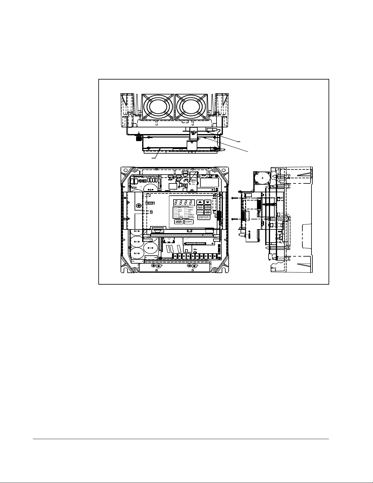
Refer to figure 2.15 for component locations.
POWER CONNECTIONS
FULL SHIELD TABS IN AND ROTATE SHIELD OUT
CONNECT USING 360MCM TWO HOLE TERMINAL LUGS
TORQUE TO 3 25IN-LB
DC–
GND
GND
WT1 WT2VRL1WWT3
DC+
U
DC+
DC–
DANGER
SL2 T
RST
Wiring Tray
Power Module
Interface Board
figure 2.15.
RUNNI NG
RPM
REMOTE
VOLTS
JOG
AMPS
AUTO
Hz
FORWAR D
Kw
REVERSE
TORQUE
PROGRAM
Passwo rd
ENTER
STOP
START
RESET
Front View
Figure 2.15 – GV3000/SE Drive (200 to 400 HP)
Step 3.1 Record connections to the Regulator board terminal strip if they must be
disconnected to remove the keypad bracket.
Step 3.2 Use a magnetic screwdriver to remove the four screws and lock washers
that fasten the keypad bracket to the hinged mounting panel. Hold the
keypad bracket as you remove the screws.
Step 3.3 Disconnect the Regulator board ribbon cable from the Power Module
Interface board.
Step 4. Install the ControlNet Option Board
Keypad
Regulator
Board
Network
Option
Board
Side View
(Enlarged)
2-32
Step 4.1 Remove the ControlNet option board from its anti-static wrapper.
The ControlNet option board mounts on four standoffs behind the
Regulator board.
Step 4.2 Align the ControlNet option board’s four mounting holes with the four
standoffs on the hinged mounting panel of the drive.
GV3000/SE AC Drive ControlNet Network Communication Option Board
Page 45

Step 4.3 Fasten the board to the drive with four ″ nuts. Metal nuts must be used
for proper grounding of the ControlNet option board.
Step 4.4 Connect the brown wire to terminal 1 of the 2-connector terminal strip.
Connect the white wire to terminal 2.
Step 4.5 Align the key on the connector of the ControlNet option board ribbon cable
with the key on the Regulator board connector. Press the ribbon cable
connector in until it locks into position.
Step 4.6 Route the Network Drop Cable through the signal wiring tray on the right
side of the drive.
Step 5. Reinstall the Keypad Bracket in the Drive
Step 5.1 Align the key on the connector from the Regulator board with the key of the
connector on the Power Module Interface board. Press the ribbon cable
connector in until it locks into position.
Step 5.2 Reconnect the keypad bracket to the hinged mounting panel using the four
screws removed earlier.
Step 5.3 Reconnect any wiring that was removed from the Regulator board.
Step 5.4 Close and secure the outer cabinet door of the drive.
This completes the hardware installation of the ControlNet option board. Do not
remove the lockout and tag until you have completed section 2.9, which provides
instruction on connecting to the ControlNet network.
7
⁄
32
Installation
2-33
Page 46

2.8 Installing the ControlNet Option Board in 2 to 43 Amp
GV3000/SE Bookshelf Drives
ATTENTION:Only qualified electrical personnel familiar with the
construction and operation of this equipment and the hazards involved
!
should install, adjust, operate, or service this equipment. Read and
understand this manual and other applicable manuals in their entirety
before proceeding. Failure to observe this precaution could result in
severe bodily injury or loss of life.
ATTENTION:The drive is at line voltage when connected to incoming
AC power. Disconnect, lock out, and tag all incoming power to the drive
before performing the following procedure. Failure to observe this
precaution could result in severe bodily injury or loss of life.
ATTENTION:DC bus capacitors retain hazardous voltages after input
power has been disconnected. After disconnecting input power, wait five
minutes for the DC bus capacitors to discharge and then check the
voltage with a voltmeter to ensure the DC bus capacitors are discharged
before touching any internal components. Failure to observe this
precaution could result in severe bodily injury or loss of life.
ATTENTION:The drive contains ESD- (Electrostatic Discharge)
sensitive parts and assemblies. Static control precautions are required
when installing, testing, servicing, or repairing the drive. Erratic machine
operation and damage to, or destruction of, equipment can result if this
procedure is not followed. Failure to observe this precaution can result
in bodily injury.
Use the procedure in this section to install the ControlNet option board in the drives
listed in
This procedure requires access to the right side of the drive. Remove the drive from
the panel if necessary.
table 2.6.
Table 2.6 – Model Numbers for 2 to 15 Amp and 24 to 43 Amp Drives
2 to 15 Amp 24 to 30 Amp 43 Amp
31ER40xx
31ET40xx
38ER40xx
38ET40xx
55ER40xx
55ET40xx
85ER40xx
85ET40xx
126ER40xx
126ET40xx
150ER40xx
150ET40xx
240ER40xx
240ET40xx
300ER40xx
300ET40xx
430ER40xx
430ET40xx
2-34
GV3000/SE AC Drive ControlNet Network Communication Option Board
Page 47

Unless otherwise indicated, keep all hardware that is removed. You will need it for
reassembly. This includes screws, lock washers, and rivets.
Important: Read and understand the warning labels on the outside of the drive
before proceeding.
Step 1. Shut Down the Drive
Step 1.1 Disconnect, lock out, and tag all incoming power to the drive.
Step 1.2 Wait five minutes for the DC bus capacitors to discharge.
Step 1.3 Disconnect all faceplate wiring.
Important: The cover is connected to the drive by the keypad/display cable. To
disconnect the cover, use the procedure below. Do not remove the
keypad/display.
Step 1.4 Remove the cover as follows:
a. Unscrew the attaching screw on the cover.
b. Lift the cover and carefuly take it out of the heatsink as far as the flat
ribbon keypad cable will allow. This cable connects the display with the
Regulator board.
c. Use a screwdriver to slide the cable out of the connector on the
Regulator board to competely detach the cover.
Step 1.5 24 to 43 A drives only: Remove the front panel by unscrewing the two
attaching screws.
Step 2. Verify that the DC Bus Capacitors are Discharged
Step 2.1 Use a voltmeter to verify that there is no voltage at the drive’s AC input
power terminals (R/L1, S/L2, T/L3). Refer to figure 2.16 or 2.19 for the
location of these terminals.
Step 2.2 Ensure that the DC bus capacitors are discharged. To check
DC bus potential:
a. Stand on a non-conductive surface and wear insulated gloves.
b. Use a voltmeter to measure the DC bus potential at the DC bus power
terminals ((–)45, (+)
47) shown in figure 2.16 or 2.19.
Step 2.3 24 to 43 A drives only: Reattach the front panel after checking the DC bus
potential.
Installation
2-35
Page 48

Cover Screw
AC Input Power
Te r mi n al s
(L1, L2, L3)
DC Bus
Measuring Points
(-)45, (+)47
Breakout Panel
2-36
Figure 2.16 – 2 to 15 Amp GV3000/SE Bookshelf Drives
GV3000/SE AC Drive ControlNet Network Communication Option Board
Page 49

Front Panel Screws
Cover Screw
Breakout Panel
Installation
Figure 2.17 – 24 to 30 Amp GV3000/SE Bookshelf Drives
2-37
Page 50

Cover Screw
Front Panel
Screws
*AC Input Power
Terminals
(L1, L2, L3)
28-31
PE L1 L2 L3
45 47 48 U V W
*Terminals are located
behind the cover and
front panel.
Figure 2.18 – 43 Amp GV3000/SE Bookshelf Drives
Breakout Panel
*DC Bus
Measuring Points
(-)45, (+)47
2-38
GV3000/SE AC Drive ControlNet Network Communication Option Board
Page 51

AC Input Power
Terminals
(L1, L2, L3)
DC Bus
Measuring Points
(–)45, (+)47
Keypad/Display
Cable Connector
Regulator
Board
Regulator Board
Ribbon Cable
Figure 2.19 – 24 to 30 Amp GV3000/SE Bookshelf Drive (Cover and Front Panel Removed)
ATTENTION:The drive contains ESD- (Electrostatic Discharge)
sensitive parts and assemblies. Static control precautions are required
!
when installing, testing, servicing, or repairing the drive. Erratic machine
operation and damage to, or destruction of, equipment can result if this
procedure is not followed. Failure to observe this precaution can result
in bodily injury.
Step 3. Install the ControlNet Option Board in the Drive
Step 3.1 Remove the ControlNet option board from its anti-static wrapper.
Step 3.2 Align the key on the connector of the ControlNet option board ribbon cable
with the key on the Regulator board connector. Press the ribbon cable
connector in until it locks into position.
Step 3.3 Fasten the ControlNet option board to the drive using the screws provided.
Step 3.4 Connect the brown wire of the Network Drop Cable to terminal 1 of the
2-connector terminal strip. Connect the white wire to terminal 2.
Installation
2-39
Page 52

Keypad/Display
Cable Connector
Regulator Board
Regulator Board
Ribbon Cable
ControlNet Option
Board
Step 4. Reattach the Cover
Step 4.1 Remove enough tabs on the faceplate breakout panel to allow the Network
Drop Cable through.
Step 4.2 Route the Network Drop Cable through the breakout panel.
Step 4.3 Reconnect the keypad/display cable to the cover.
Important: Check that the display cable is reconnected to the Regulator board. You
will need to fold and route the cable under the heatsink before replacing
the cover.
Step 4.4 Reattach the cover using the single faceplate screw.
Step 4.5 Reconnect all faceplate wiring.
This completes the hardware installation of the ControlNet option board. Do not
remove the lockout and tag until you have completed section 2.9, which provides
instruction on connecting to the ControlNet network.
Figure 2.20 – Installing the ControlNet Option Board
2-40
GV3000/SE AC Drive ControlNet Network Communication Option Board
Page 53

2.9 Connecting the GV3000/SE Drive to a
ControlNet Network
ATTENTION:Do not let any metallic surfaces on the BNC connectors,
plugs, or optional accessories touch grounded metallic surfaces. This
!
The ControlNet network is composed of:
• trunk cables
• drop cables (run from a tap on the trunk cable to a node)
• taps
• terminators
• repeaters
Refer to your ControlNet Network Planning and Installation manual for a detailed
description of how to install a ControlNet network and add a drop to an existing
ControlNet network.
Step 4.1 Stop any application tasks that are running.
contact could ca use noise on the network. Failure to follow this precaution
could result in damage to equipment.
Step 4.2 Remove the lockout and tag. Apply power to the drive. SELF is displayed
while the drive performs power-up diagnostics. If there is an error during
diagnostics, it is logged. See your drive software manual for information on
errors.
Step 4.3 Connect a ControlNet Network drop cable to one of the BNC connectors on
the option board. Connect the other end to a tap.
See figure 2.21 for cabling and termination connections.
Installation
2-41
Page 54

Channel B
GV3000/SE Drive
Note: This diagram shows
redundant media
being used.
Figure 2.21 – Connecting a GV3000/SE Drive to the ControlNet Network
You can run a second trunk cable between your ControlNet nodes for redundant
media.With redundant media, nodes send signals on two separate segments. The
receiving node automatically compares the quality of the two signals and accepts the
better signal. This also provides a backup cable should one cable fail. When using
redundant media, you must use two passive taps.
Channel A
Repeater
Trunk Cable
Programmable
Logic Controller
(PLC)
Drop Cable
Ta p
Terminator
2-42
If you do not use redundant media, the option board can operate using only channel A
or channel B, as long as all other drops on the network are using the same channel.
2.10 Connecting a Programming Device to the Option
Board’s Network Access Port
You can gain full access to the ControlNet network by connecting a programming
device to the option board’s network access port, an RJ-45 connector.
Important: Be sure to use a network access cable that is approved by a ControlNet
vendor. Using an unsuitable cable could result in possible network
failures.
GV3000/SE AC Drive ControlNet Network Communication Option Board
Page 55

Setting Up the GV3000/SE Drive
This chapter describes how to configure a GV3000/SE drive for use with a ControlNet
network. The sections that follow describe the GV3000/SE parameters related to
ControlNet operation.
3.1 Setting the Control Type (P.048)
The first parameter that must be set up is P.048 (Volts/Hertz or Vector Regulation).
This parameter is used to select the control type as volts/hertz or vector. All units ship
from the factory with the control type set to volts/hertz (P.048 = U-H). If this is not the
desired mode of operation, you must change P.048.
Important: When P.048 is changed, all P parameters (except P.048 and P.049) are
reset to their default values.
Parameter P.048 cannot be written over the ControlNet network.
Parameter Range: U-H = V/Hz control
UEC = vector control
CHAPTER 3
Default Setting: U-H
Parameter Type: Non-volatile, Configurable
(Read Only over the ControlNet network)
Setting Up the GV3000/SE Drive
3-1
Page 56

3.2 Setting the Node Number (P.060)
Use parameter P.060 (Network Drop Number) to assign a node number to the
GV3000/SE drive. The node number can be changed (through a local operator
interface) only when the drive is stopped. This parameter cannot be written over the
ControlNet network .
The node number must be changed to a value greater than 1 to begin ControlNet
communication. After the network has been configured and after parameter P.060 is
set to a value greater than 1, the LEDs on the network option board should turn solid
green to indicate that communication is active.
If the node number is changed from any value other than 1, the power to the drive
must be turned off and back on to have the new value take effect. If parameter P.060 is
not equal to 1 on power-up, the drive will attempt to begin communicating on
ControlNet immediately after the drive diagnostics complete.
Parameter Range: 1-99
Default Setting: 1
Parameter Type: Non-volatile, Configurable
(Read Only over the ControlNet network)
3.3 Setting the Control Source (P.000)
Use parameter P.000 (Control Source) to determine the source of control information
for the drive (start, jog, direction, etc.). To start and stop the drive over the network,
parameter P.000 must be set to OP. This parameter can be written over the ControlNet
network only when the drive is stopped.
After parameter P.000 is set to OP, the Remote LED on the keypad should turn on to
show the network is in control of the drive. Note that parameter P.000 does not prevent
the drive from communicating on ControlNet; it only allows the drive to be controlled,
and the reference to be supplied, from ControlNet. Parameter P.000 does not have to
be set to OP to modify or read drive parameters.
Parameter Range: LOCL = Local keypad/display
rE = Terminal strip remote inputs
OP = Option port
SErL = Serial port (CS3000 or OIM)
Default Setting: LOCL
Parameter Type: Non-volatile, Configurable
3-2
GV3000/SE AC Drive ControlNet Network Communication Option Board
Page 57

3.4 Setting the Run/Program Response (P.061)
ATTENTION:This parameter allows you to configure the drive to
continue to run when the PLC is put into program mode. You must provide
!
Use parameter P.061 to select how the drive responds when communicating with a
programmable controller while the programmable controller is in program mode. This
parameter can be written over the ControlNet network. Note that the Function Loss
input on the terminal strip remains active at all times regardless of the setting of this
parameter.
When P.061 = 0 (Stop), the drive stops when the programmable controller is put into
program mode. The drive can be started only when the programmable controller is in
run mode.
When P.061 = 1 (Not Stop), the drive does not stop when the programmable controller
is put into program mode. The drive can be started when the programmable controller
is in either program or run mode.
When P.061 = 3 (Use terminal strip digital inputs), the drive uses the terminal strip
inputs for start, stop, reset, and run/jog when the programmable controller is put into
program mode. Depending on how P.007 and P.008 are configured, the drive may also
use the terminal strip inputs for forward/reverse, ramp 1/2, torque/speed, MOP up,
MOP down, and preset speed selection. The only terminal strip signal that cannot be
used is rem/loc. The function loss digital input remains active at all times. While the
programmable controller is in program mode, the speed reference is the analog input,
the MOP, or one of the preset speeds, depending on the value of P.008 and the
configured digital inputs. When the programmable controller returns to run mode, the
drive transfers the control source back to the ControlNet network.
some form of hardwired stop, since stopping the drive through the
network might not be possible. Failure to observe this precaution could
result in bodily injury or damage to, or destruction of, equipment.
Setting Up the GV3000/SE Drive
Parameter Range: 0 = Stop
1 = Not Stop
3 = Use terminal strip control
Default Setting: 0
Parameter Type: Non-volatile, Tunable
3-3
Page 58

3.5 Setting the Communication Loss Response (P.062)
ATTENTION:This parameter allows you to configure the drive to
continue to run if a loss of network communication occurs. You must
!
Parameter P.062 defines how the drive responds when a loss of scheduled
communication is detected. This parameter can be written over the ControlNet
network.
When P.062 = 0 (IET fault), the drive will fault stop when loss of communication is
detected.
When P.062 = 1 (Hold last reference), the drive maintains the last reference until
communication is re-established and the programmable controller has completed one
scan to evaluate a new drive reference value.
If network communication is re-established, the drive will again follow the reference
and sequencing control inputs supplied by the network master. Note that if P.054
(Level Sense Start Enable) = ON and the start and stop inputs are on (1), the drive
may start.
provide some form of hardwired stop in case of communication loss,
since stopping the drive through the network might not be possible.
Failure to observe this precaution could result in bodily injury or damage
to, or destruction of, equipment.
ATTENTION:In volts/hertz regulation, if P.000 (Control Source) is set to
OP (Option Port), and P.062 is set to 1 (Hold Last Reference), and the
!
When P.062 = 2 (Use terminal strip reference), the drive uses the terminal strip analog
input for the reference value if P.008 = 0. If P.008
After communication is re-established and the programmable controller has
completed one scan to evaluate a new drive reference value, ControlNet will resume
control. Note that when using this setting, the terminal strip Stop input must be
maintained for the drive to run.
Note that if P.054 (Level Sense Start Enable) = OFF and the drive is stopped while in
this mode, it cannot be restarted until network communication is re-established or the
Control Source (P.000) is changed.
drive loses communication with the network, the drive will maintain the
last frequency command sent to it. Ensure that drive machinery, all
drive-train mechanisms, and application material are capable of safe
operation at the maximum operating speed of the drive. Failure to
observe this precaution could result in bodily injury.
ATTENTION:In vector regulation, if U.000 (Torque Reference Source)
is set to 2 (Option Port), and P.062 is set to 1 (Hold Last Reference), and
the drive loses communication with the network, the drive will no longer
be regulating speed. Instead, motor speed will vary according to the load,
up to the overspeed limit. Ensure that driven machinery, all drive-train
mechanisms, and application material are capable of safe operation at
the maximum operating speed of the drive. Failure to observe this
precaution could result in bodily injury.
≠ 0, the selected source will be used.
3-4
Also note that if P.054 (Level Sense Start Enable) = ON and the start and stop inputs
are on (1), the drive may start.
GV3000/SE AC Drive ControlNet Network Communication Option Board
Page 59

ATTENTION:If P.062 = 2 and P.054 (Level Sense Start Enable) = ON
and network communication is lost while the drive is running, the terminal
!
When P.062 = 3 (Use terminal strip control), the drive uses the terminal strip inputs for
start, stop, reset, and run/jog when loss of communication is detected. Note that if
P.054 (Level Sense Start Enable) = ON and the start and stop inputs are on (1), the
drive may start.
Depending on how P.007 and P.008 are configured, the drive may also use the
terminal strip inputs for forward/reverse, ramp 1/2, torque/speed, MOP up, MOP down,
and preset speed selection. The only terminal strip signal that cannot be used is
rem/loc. The function loss digital input remains active at all times.
While communication is lost, the speed reference is the analog input, the MOP, or one
of the preset speeds, depending on the value of P.008 and the configured digital
inputs. When network communication is re-established, the drive will again follow the
reference and sequencing control inputs supplied by the network master. Note that if
P.054 = ON and the network start and stop commands are on (1), the drive will start.
Important: The drive regulator may become operational before the ControlNet
strip stop input will function as a STOP/RUN input. If the terminal strip
stop input is opened, the drive will stop. If the terminal strip stop input is
closed, the drive will re-start. Failure to observe this precaution could
result in severe bodily injury or loss of life.
network becomes active (sending and receiving start/stop commands). If
this occurs, the drive will start on power up when P.062 = 3 and all of the
following conditions are true:
• P.000 (Control Source) = OP
• P.054 (Level Sense Enable) = ON
• The terminal strip stop input is closed
• The terminal strip function loss input is closed
• The terminal strip start signal is closed and maintained.
When communication is established and the network becomes active, the
drive will receive its start/stop commands from the network.
When P.062 = 4 and an nCL or F62 error occurs, then the drive will operate as
described above for P.062 = 3.
ATTENTION:F62 indicates a watchdog timeout on the ControlNet
Interface Module. This normally results in drive shutdown with the F62
!
fatal fault annunciated. The F62 is typically a result of faulty interface
module hardware. It can also occur as a result of excess noise generated
during an event that severs the control net cable. This mode of operation
should be used only in applications where motor stoppage would result
in damage to costly equipment. Failure to observe this precaution could
result in damage to equipment.
Setting Up the GV3000/SE Drive
3-5
Page 60

Parameter Range: 0 = IET fault
1 = Hold last reference
2 = Use terminal strip reference
3 = Use terminal strip control
4 = Use terminal strip control for nCL or F62
Default Setting: 0
Parameter Type: Non-volatile, Tunable
Refer also to parameters: N/A
3.6 Setting the Network Output Register Sources P.066
to P.069)
Parameters P.066 through P.069 define the signals written to network output registers
1 through 4. These parameters can be written over the ControlNet network.
Figure 3.1 provides a graphical representation of these parameters.
Parameter Range: 0 = (P.066) Motor Kw display value
(P.067) Motor torque display value*
(P.068) Output power factor
(P.069) Encoder counter (x4)*
1 = Speed reference rate limit output
2 = Speed reference at the ref/fdbk summing
junction (includes OCL output and current
compounding)*
3 = Speed loop feedback*
4 = Speed loop error*
5 = Speed PI output*
6 = Outer control loop feedback*
7 = Outer control loop error*
8 = Outer control loop output*
9 = Terminal strip analog input normalized to speed
(see Appendix G)
10 = Terminal strip analog input scaled (see
Appendix G)
11 = Torque reference*
12 = Torque feedback*
*
3-6
Default Setting: 0
Parameter Type: Tu na bl e
Refer also to parameters: N/A
*
These signals are valid only in vector control (P.048 = UEC).
GV3000/SE AC Drive ControlNet Network Communication Option Board
Page 61

P.066
0 = Motor KW
display value
.
.
.
12
P.067
0 = Motor torque
display value
.
.
.
12
P.068
0 = Output power
factor
.
.
.
12
P.069
0 = Encoder
counter (x 4)
.
.
.
12
Network Module
Network Output Register 1
Network Output Register 2
Network Output Register 3
Network Output Register 4
Figure 3.1 – Signal Selection for Network Output Registers
3.7 Option Port: Type and Version (P.065)
Parameter P.065 displays the option type and the software version number of the
network option board. This parameter is read only over the ControlNet network.
The display format is N.vvv, where N represents the option type (1 = RMI,
2 = AutoMax network, 4 = DeviceNet network, and 5 = ControlNet network) and vvv
represents the software version number.
For example, if 5.602 is displayed, it means the drive is using the ControlNet network
option and is running software version 6.02.
3.8 Network Reference Source (P.063) and Network Trim
Reference Source (P.064)
Parameters P.063 and P.064 are not used with the ControlNet Network Option board.
Do not write to these parameters.
Setting Up the GV3000/SE Drive
3-7
Page 62

3-8
GV3000/SE AC Drive ControlNet Network Communication Option Board
Page 63

CHAPTER 4
Programming the Drive
This section describes how to program the drive over the ControlNet network.
4.1 About ControlNet Network Communication
The ControlNet network transports time-critical control information (e.g. drive
reference and feedback information) as well as non-time-critical information (e.g.
accessing drive parameters). The transportation of the non-time-critical information
does not interfere with the time-critical messages.
A node’s access to the network is controlled by a time-slice access algorithm, which
determines a node’s opportunity to transmit in each network update interval. You
configure how often the network update interval repeats by selecting a network update
time in milliseconds. The minimum network update time you can specify is 2 msec.
See table 4.1 below for more information about the components of the network update
time.
Table 4.1 – Network Update Time Components
This network update
time component
scheduled Information that is
feedback) should be sent during this part of the NUT
interval.
unscheduled Information that
should be sent during this part of the NUT interval.
can be delivered without time constraints
time-critical
Allows:
(drive reference and
4.2 Configuring Drive Reference and Feedback Data as
Programming the Drive
The amount of time available for the unscheduled portion is
determined by the traffic load of the scheduled portion.
During this part of the interval, nodes may have many or no
chances to transmit.
For optimum throughput, assign addresses to ControlNet nodes in a sequential order.
Scheduled Transfers
This section describes how to:
• configure scheduled traffic for the GV3000/SE drive
• control the drive using the drive reference data
• use scheduled drive feedback data
4-1
Page 64

4.2.1 Configuring Scheduled Data Transfers
Before the drive can communicate on the ControlNet network, you must configure its
scheduled traffic information by using some type of ControlNet configuration software.
By configuring scheduled traffic, you define how much data the drive will send, how
often the data is sent, and where the data is written to and read from (mapped) in the
programmable controller.
You must configure each drive on the ControlNet network. Table 4.2 lists the
configuration information you must enter.
Table 4.2 – ControlNet Scheduled Traffic Configuration Information
In this field: Enter this information:
Node Enter the drive’s node number that you defined in P.060.
Slot
Message
Module Enter GV3000/SE.
API This field is read only.
RPI Enter how often you want to exchange scheduled data between
Connection Type Select “Exclusive Owner.”
Input Address Enter the programmable controller’s input file number that will
Input Size Enter the number of words of drive feedback data that you want
Output Address Enter the programmable controller’s output file number that will
Output Size Enter the number of words of drive reference data that you want
Status Address Enter the programmable’s integer file number that will store the
Config Address
Config Size
These fields are not used by the GV3000/SE drive.
the programmable controller and the drive.
The GV3000/SE does not support Multicast operation.
store data received from the drive (drive feedback data).
the programmable controller to receive from the drive (1 to 6).
See section 4.2.3 for information about the type of data that is
sent.
store data sent to the drive (drive reference data).
the programmable controller to send to the drive (1 to 6).
See section 4.2.2 for information about the type of data that is
sent.
status of the ControlNet connection to the drive.
These fields are not used by the GV3000/SE drive.
4-2
GV3000/SE AC Drive ControlNet Network Communication Option Board
Page 65

Word: Bit: Description:
Word 0 –
Drive Control
4.2.2 Programming Scheduled Drive Reference Data
To control the drive over the ControlNet network with the scheduled drive reference
data, parameter P.000 must be set to OP, specifying the option board as the drive’s
control source. The programmable controller controls the drive by using the drive
reference data, which is transmitted over the ControlNet network as scheduled data.
You can write from one to six words of data to the file you defined during drive
configuration as the Output Address. The value you defined as the Output Size
determines how many words of data the option board can accept from the
programmable controller. During a scheduled data transfer, the programmable
controller writes the data contained in the Output Address to the option board.
Scheduled drive reference data is composed of from one to six words. The first word
of the scheduled drive reference data is always the drive control word. Should you
configure less than six words of output data, you can access the drive reference data
through file N12 as an unscheduled data transfer. See section 4.3.
Table 4.3 describes the function of each word of the scheduled drive reference data.
Table 4.3 – Scheduled Drive Reference Data
— Set and reset (clear) the bits in this word via your
programmable controller application program to control the
state of the drive.
The drive control bits that are used for drive sequencing are
evaluated in the drive every 20 msec.
0
Start
Use this bit to start the drive.
When the drive is in run mode, a 0-to-1 transition starts the
drive.
Programming the Drive
1
Stop
2
Fault Reset
3
Run/Jog
4
Forward/Reverse
5
OCL Enable
When the drive is in jog mode, a value of 1 jogs the drive. A
value of 0 stops the drive.
Use this bit to stop the drive.
0 = stop the drive
1 = allow the drive to run
Use this bit to reset latched faults. Faults are reset via a
transition from 0 to 1. The error log in unaffected by this bit.
Use this bit to select run or jog mode.
0 = run mode
1 = jog mode
Use this bit to select the direction of the drive.
0 = forward
1 = reverse
Use this bit to enable the Outer Control Loop.
0 = OCL disabled
1 = OCL enabled
4-3
Page 66

Table 4.3 – Scheduled Drive Reference Data (Continued)
Word: Bit: Description:
7
Use this bit to select torque or speed regulation.
Torque/Speed
The drive must be configured for vector control
(P.048 = UEC and U.000 = 3).
0 = torque regulation
1 = speed regulation
8
Error Log Clear
Use this bit to reset the error log.
The error log resets when this bit transitions from 0 to 1.
The latched faults are not affected by this bit.
Word 1 –
Speed/Torque Reference
1, 2
— Use this word to control a speed or torque reference.
When using volts per hertz (V/Hz) control, a value of 4095
corresponds to the frequency in parameter P.004
(Maximum Speed).
When using vector speed regulation, a value of 4095
corresponds to the speed in parameter U.017.
When using torque regulation, a value of 4095 corresponds
to 150% of rated torque.
Word 2 –
Tr i m R efe re n ce
1
— Use this word to control the trim reference value. The
scaling for the trim reference is the same as the speed
reference. This word is not used for torque regulation.
Word 3 –
Inertia Compensation
1
— Use this word to provide the inertia compensation input to
the speed loop. To to use this data, you must set bit 1 of
parameter P.030.
Word 4 –
Speed PI High Limit
1
— Use this word to modify the speed loop PI high limit. The
output of the speed PI will not be greater than this value. A
value of 4095 represents 150% of the rated torque. To use
this data, set bit 2 of parameter P.030.
Word 5 –
Speed PI Low Limit
2
— Use this word to modify the speed loop PI low limit. The
output of the speed PI will not be less than this value. A
value of -4095 represents -150% of the rated torque. To use
this data, set bit 2 of parameter P.030.
1
If the drive is configured as a speed regulator, the speed reference, trim reference, inertia compensation, and PI limits are used in the
speed loop, which is evaluated every 5 msec.
2
If the drive is configured as only a torque regulator, the torque reference is used in the torque loop, which runs every 500 µsec. The fastest
network update time is 2 msec, so in torque mode the drive uses the same torque reference value a minimum of four times.
4-4
4.2.3 Using Scheduled Drive Feedback Data
The drive feedback data provides status to the programmable controller. This data is
sent over the ControlNet network as scheduled data, which is transmitted at the
configured update rate. However, the drive sends the feedback data to the option
board every 5 msec. Feedback data is sent to the option board regardless of the value
of parameter P.000.
GV3000/SE AC Drive ControlNet Network Communication Option Board
Page 67

Scheduled drive feedback data is composed of from one to six words. The value you
defined as the Input Size determines how many words of data the programmable
controller accepts from the option board. During a scheduled data transfer, the option
board writes the data contained in the Input Address to the programmable controller.
The first word of the scheduled drive feedback data is always the drive status word.
Should you configure less than six words of input data, you can access the drive
reference data through file N12 as an unscheduled data transfer. See section 4.3.
Table 4.4 describes the function of each word of the scheduled drive feedback data.
Table 4.4 – Scheduled Drive Feedback Data
Word: Bit: Description:
Word 0 –
Drive Status
— The drive writes to these bits to provide status about the drive.
0
Drive Ready
This bit indicates the status if the drive is ready.
0 = interlock missing
1 = drive ready
1
Drive Running
This bit indicates whether the drive is running.
0 = stopped
1 = running
2
Fault Active
This bit indicates whether the drive has faulted.
0 = no fault
1 = fault
3
Run/Jog
This bit indicates whether the drive is in run or jog mode.
0 = run
1 = jog
4
Forward/Reverse
This bit indicates the drive’s direction.
0 = forward
1 = reverse
5
Stop in Progress
Use this bit to determine the drive’s stopping status.
0 = not stopping
1 = stopping
6
Auto/Manual
This bit indicates whether the drive is in auto or manual mode.
0 = auto
1 = manual
7
Torque/Speed
This bit indicates whether the drive is using torque or speed control.
0 = torque
1 = speed
8
This bit indicates the status of digital input 1.
Digital In 1 (Start)
9
This bit indicates the status of digital input 2.
Digital In 2 (Stop)
Programming the Drive
4-5
Page 68
Table 4.4 – Scheduled Drive Feedback Data (Continued)
Word: Bit: Description:
10
This bit indicates the status of digital input 3.
Digital In 3
(Reset)
11
This bit indicates the status of digital input 4.
Digital In 4
(Run/Jog)
12
This bit indicates the status of digital input 5.
Digital In 5 (FL)
13
This bit indicates the status of digital input 6.
Digital In 6
14
This bit indicates the status of digital input 7.
Digital In 7
15
This bit indicates the status of digital input 8.
Digital In 8
Word 1 –
Speed Reference
Word 2 –
Selected Output 1
Word 3 –
Selected Output 2
Word 4 –
Selected Output 3
Word 5 –
Selected Output 4
— This word indicates the speed reference being used by the drive.
Values range from ±4095.
— This word indicates the value selected in parameter P.066. See table
4.5.
— This word indicates the value selected in parameter P.067. See table
4.5.
— This word indicates the value selected in parameter P.068. See table
4.5.
— This word indicates the value selected in parameter P.069. See table
4.5.
4-6
Table 4.5 explains the values that are available for words 2 - 5.
Table 4.5 – Signals That Can Be Displayed in Words 2 - 5
Value: Parameters
P.066 P. 0 6 7 P. 0 6 8 P. 0 6 9
0 Motor KW Motor Torque Power Factor Encoder Counts
1
2
3
4
5
6
7
Speed reference limited output
Speed reference plus OCL output
Speed feedback
Speed error
Speed PI output
OCL feedback
OCL error
GV3000/SE AC Drive ControlNet Network Communication Option Board
1
1
1
1
1
1
1
Page 69
Table 4.5 – Signals That Can Be Displayed in Words 2 - 5
Value: Parameters
8
OCL output
1
9 Terminal Strip Analog Input (Normalized)
10 Terminal Strip Analog Input
11
12
1
These signals are valid only in vector control.
Torque Reference
Torque Feedback
4.3 Using Unscheduled Transfers
Use the unscheduled transfer portion of the network update time (NUT) to:
• read and write drive parameters that are not time-critical
• read drive display data
• read and write drive reference and feedback data that are not time-critical
• read the status of Typed Write messages.
In a PLC-5, you can use the MSG instruction to initiate unscheduled transfers.
1
1
4.3.1 Programming the MSG Instruction in a PLC-5
By including the PLC-5 MSG instruction in your application program you can read data
from the drive and write data to the drive during the unscheduled transfer time. You
can have up to four MSG instructions enabled at the same time.
Figure 4.1 shows an example of an MSG instruction in a PLC-5.
Sets when the block is enabled
Sets when a response has been received by the
programmable controller
Sets when an error occurs during the response
MSG
Read/Write Message
Control block
Setup Screen
Lets you configure the
MSG instruction.
Defines the file in the programmable
controller that stores the details
about the message.
MG40:0
MG = message file type
40 = file number
0 = element 0
(EN)
(DN)
(ER)
Programming the Drive
Figure 4.1 – An Example of a MSG Instruction in a PLC-5
4-7
Page 70

To configure the MSG instruction, you must enter information about the data’s
location, size etc. Use table 4.6 to help you.
Table 4.6 – MSG Configuration Information
In this field: Do this:
PLC-5 Configuration
Communication Command To read information from the drive, enter PLC5
Typed Read.
To write data to the drive, enter PLC5 Typed Write.
Data Table Address When reading information from the drive, enter the
file in which you want to store the data received
from the drive.
When writing information to the drive, enter the file
that will contain the data you want to send to the
drive.
Size in Elements Enter the number of words to read or write. The
largest size you can use depends upon which file is
being accessed.
Por t Number Enter 2 to select ControlNet communication.
Target Device Configuration
Data Table Address Enter the file in the drive where you want to read
data from or write data to. See section 4.3.3
ControlNet Path Enter the node number of the drive.
4.3.2 About MSG Instruction Timing
When a Typed Read message is sent to the drive, the response is sent to the PLC-5
programmable controller in under 20 msec. When a Typed Write message is sent to
the drive, the message is first processed by the drive. Therefore, 100-200 msec may
elapse before the response is returned to the PLC-5 programmable controller. These
times are applicable only when the network update time and unscheduled traffic
bandwidth are not limiting factors.
4.3.3 About the Files You Can Access
When you send an unscheduled message to the drive, the data table address you
specify for the target device determines what drive information you want to access.
The data table address is in the form of:
Nff:eee
where
: N specifies the file type as integer, ff is the file number, and eee is the
element number (word).
The GV3000/SE ControlNet Option Board supports these file numbers:
• N10 – Drive parameters (read and write)
• N11 – Drive display data (read only)
• N12 – Drive reference and feedback data (read and write)
4-8
• N20 – Status of the most recent write parameter command (read only)
GV3000/SE AC Drive ControlNet Network Communication Option Board
Page 71

Figure 4.2 shows how the drive information maps to the drive information integer files.
Unscheduled Data Transfers (MSG) Instruction
File in
Drive
N10:0
N10:100
N11:0
Option
Board
Drive
Information
N10:99
P. 0 0 0
P. 0 9 9
N10:148
H/U.000
H/U.048
N11:14
Drive
Display
Data
Scheduled Data Transfers
Figure 4.2 – Drive Information Map
4.3.4 Using the Drive Parameters Data (N10:X)
Use file N10 to access drive parameters with unscheduled data transfers. Parameters
P.000 through P.099 map to N10:0 to N10:99. The H (Volts/Hertz) and U (Vector)
parameters map to N10:100 to N10:148 and share the same element numbers.
You can access all the parameters with one MSG instruction. By specifying only a
range of words in the MSG instruction, you can change any subset of contiguous
parameters without sending a complete new copy of the file to the drive.
N12:0
N12:31
Reference
and
Feedback
Data
N20:0
N20:148
Write
Status
4.3.5 Using the Drive Display Data (N11:X)
Programming the Drive
See chapter 5 for a complete listing of the parameters and the drive file elements to
which they are mapped.
Use file N11 to access the drive display data. This file lets you access information
such as the drive fault bits, information about the motor, and the error log.
The GV3000/SE drive updates the drive display data every 100 msec. The drive
operation data is averaged over a 500 msec period. See chapter 5 for a complete
listing of the data you can access and its location.
4-9
Page 72

4.3.6 Using the Drive Reference and Feedback Data (N12:X)
When you use scheduled data transfers to transmit less than six words of either drive
reference or feedback data, you can access the information that is not transmitted as
scheduled data by using unscheduled data transfers. Use a MSG instruction to access
any or all of the data, except the drive control word, which is read only. See chapter 5
for a complete listing of the data you can access and its location.
4.3.7 Using the Write Status File (N20:X) to Troubleshoot a Drive
Parameter Write Command
You can troubleshoot errors that may occur when you write values to parameters in
the drive. The drive may not accept the values because the drive is running or the
value is less than the minimum value or greater than the maximum value. When this
occurs, the MSG instruction’s ER coil is set and an error code is written into an
element in N20 that corresponds to the drive parameter’s location in N10. Each
element in file the N20 corresponds to an element in file N10. For example: N10:0
stores the Control Source parameter data (P.000). If you were writing a value to N10:0
and an error occurred, you could read N20:0 and determine that an error occurred
when writing to parameter P.000.
See table 6.3 for the error codes that the drive will return to the PLC when a Typed
Read or Typed Write message fails.
4-10
GV3000/SE AC Drive ControlNet Network Communication Option Board
Page 73

CHAPTER 5
Configuring ControlLogix Applications
Chapter 5 provides information and examples that explain how to use I/O Messaging
to control, configure, and monitor scheduled and unscheduled data on a GV3000
drive using a ControlNet scanner module.
ATTENTION:The examples in this publication are intended solely for
purpose of example. There are many variables and requirements with any
!
Configuring a ControlLogix CNB scanner, and the network, is mainly done using RSLogix 5000
software (figure 5.1). RSNetWorx is still required, but only at the end of the configuration
process. Start the RSLogix 5000 software to begin the configuration process
application. Rockwell Automation does not assume responsibility or liability (to
include intellectual property liability) for actual use of the examples shown in this
publication. Failure to observe this precaution could result in bodily injury or
damage to equipment.
.
Configuring ControlLogix Applications
Figure 5.1 – RSLogix 5000: I/O Configuration Selection
5-1
Page 74

Step 1. Right-click on the I/O Configuration folder and select New Module (figure
5.2).
Figure 5.2 – RSLogix 5000: New Module Selection
Step 2. Select the ControlNet module used by the controller. In this example (figure
5.3), a 1756-CNB Series B ControlNet Bridge is selected.Click OK.
5-2
Figure 5.3 – Select Module Type: 1756-CNB/B Selection
GV3000/SE AC Drive ControlNet Network Communication Option Board
Page 75

Step 3. Enter a Name, Slot number, and Revision number (figure 5.4). Click Next>.
Figure 5.4 – Module Properties: Name Selection
Step 4. This step is used to define controller-to-module behavior (figure 5.5). Inhibit Module
inhibits/un-inhibits the connection to the module. The
if a failure on the connection of this module causes a major fault on the controller if
the connection for the module fails. Click Next>.
Major Fault check-box selects
Configuring ControlLogix Applications
Figure 5.5 – Module Properties: Controller-to-Module Behavior Screen
5-3
Page 76

Step 5. This window (figure 5.6) is displayed for informational purposes only. Click Next>.
Figure 5.6 – Module Properties: Identification/Status Screen
Step 6. This window (figure 5.7) is displayed for informational purposes only. Click Finish>>.
5-4
Figure 5.7 – Module Properties: Informational Screen
GV3000/SE AC Drive ControlNet Network Communication Option Board
Page 77

Step 7. The 1756-CNB/B now appears in the I/O Configuration folder (figure 5.8).
Figure 5.8 – RSLogix 5000: I/O Configuration Folder
Step 8. Right-click on the 1756-CNB and select New Module (figure 5.9).
Configuring ControlLogix Applications
Figure 5.9 – RSLogix 5000: New Module Selection Screen
5-5
Page 78

Step 9. To configure a GV3000 drive, select the GV300 (figure 5.10). Click OK.
Figure 5.10 – Select Drive Type: GV3000
Step 10. Enter a Name, Node number, and Revision number (figure 5.11). Click Next>.
Important: Electronic Keying should be set to disabled.
Figure 5.11 – Module Properties: Name Selection
Step 11. The Requested Packet Interval (RPI) schedules the connection to move data to or
from the module at least this often or the connection will fail with the RPI Not Valid
error. Set this value to 5 ms or greater, and click Next> (figure 5.12).
5-6
GV3000/SE AC Drive ControlNet Network Communication Option Board
Page 79

Important: The RPI time must be set greater than or equal to the Network Update Time
)
(NUT).
Figure 5.12 – Module Properties: RPI Selections
Step 12. This window (figure 5.13) is for informational purposes only. Click Finish>>.
Module Properties – Cnet Bridge: 0 (GV3000 2.1
Configuring ControlLogix Applications
Figure 5.13 – Module Properties: Cnet_Bridge
5-7
Page 80

Step 13. The configured node (“GV3000” in this example) now appears under the 1756-CNB
module in the I/O Configuration folder.
Figure 5.14 – RSLogix: Configure Additional Nodes Screen
Step 14. Repeat the previous steps for each additional node you need to configure.
Step 15. In the Data Types folder, click on the Module-Defined sub-folder. When you
create a module, module-defined data types and tags are automatically
created. These tags allow you to access the Input and Output Data of the
module via the controller’s ladder logic.
5-8
Figure 5.15 – RSLogix 5000: Module-Defined Screen
GV3000/SE AC Drive ControlNet Network Communication Option Board
Page 81

Step 16. Select Communications / Download to download the configuration to the
controller (figure 5.16). RSLogix automatically enters on-line mode when
complete.
Cnet_bridge: 0 (GV3000 2.1)
Figure 5.16 – Download to the Controller Dialog Box
Step 17. An Attention symbol is located next to the Node 2 (GV3000) icon in
figure 5.17, which indicates the ControlNet scanner needs to be configured.
Step 18. Start RSNetWorx and perform the following:
This schedules the I/O that was configured in the RSLogix 5000.
Configuring ControlLogix Applications
Figure 5.17 – RSLogix: Attention Symbol
a. Click the On-line icon and browse the network.
b. Select Edits Enabled and view the messages in the Message View for completion
(figure 5.18). The
c. Select File / Save and save the project.
d. Close RSNetworx.
icon should disappear from the nodes in the Graphical View.
5-9
Page 82

Figure 5.18 – RSNetWorx for ControlNet Screen
Step 19. The Attention symbol on the RSLogix 5000 connection tree will disappear if
the network has been configured properly. You are now ready to develop
your ladder logic program.
5-10
GV3000/SE AC Drive ControlNet Network Communication Option Board
Page 83

CHAPTER 6
Configuring SLC500 Applications
Chapter 6 describes how to configure a SLC500 PLC on a ControlNet network with a
GV 3000 drive.
Both the 1747-SCNR and 1747-KFC15 modules are required to communicate fully
with a drive and both must be configured as drops on the ControlNet network. If the
application only calls for access to Drive Reference and Feedback Data (such as Drive
Control and Status Words), and does not call for access to any N10, N11, or N12 drive
parameters, the 1747-KFC card will not be required. However, Unscheduled
Messaging will not be possible and another connection option to the processor will be
required for downloading the required ladder logic.
This chapter is intended for use by personnel familiar with the installation and
operation of the Reliance Drive and the installation, programming, I/O configuration
and operation of the SLC processor using RSLinx, RSLogix 5000 and RSNetWorx for
ControlNet software. Personnel should also be familiar with the system configuration
documentation.
6.1 Required Software and Equipment
Software and equipment required for configuring a SLC500 on a ControlNet network
is listed in table 6.1.
Table 6.1 – Required Software and Equipment
Equipment Description Version
RSLinx Software Version 2.20 or later
RSNetWorx for ControlNet software Version 2.25 or later
RSLogix 500 software Version 3.01 or later
SLC 500 Chassis w/appropriately sized Power Supply
SLC 5/03 processor (1747-L532)
or SLC 5/04 processor
ControlNet Scanner Module: 1747-SCNR
ControlNet RS-232 Interface: 1747-KFC15
PC with 1784-KXTC15 or 1784-PCIC interface card
GV3000 ControlNet Communications Board (2CN3000) Version 2.20 or later
6.2 Network Configuration
Configure the ControlNet network using RSLinx and RSNetWorx for ControlNet
software.
OS 301 or higher
Any OS
Configuring SLC500 Applications
6-1
Page 84

Using the parameters suggested in chapter 4 of this manual, configure scheduled
traffic with RSNetWorx, by doing a scanlist configuration of the 1747-SCNR module to
the drive. It is recommended that Input and Output files are used instead of M1 and
M0 files, as discrete I/O is more appropriate for critical data transfer. Make sure
keyswitch is in “program” position before download of configuration.
Input address should be [ I:x:y ] with x = slot of SCNR module and y = 1 or greater.
Output address should be [ O:x:y ] with x = slot of SCNR module and y = 1 or greater.
Input and Output size for the GV3000 drive = 6.
Important: Any address offset is limited by 31 words maximum minus the drive I/O
word size.
6-2
Figure 6.1 – Network Configuration: Connection Properties
6.3 1747-KFC15 Set Up
Unlike PLC5 or ControlLogix controllers, the unscheduled messages between the
SLC controller and the drive must pass through the KFC15 module and the serial
cable, included with the KFC15 module, that physically connects the module and the
processor.
Important: ControlNet unscheduled messaging is not fully deterministic and may be
further limited by the baud rate selected for Channel 0 (RS232/DF1)
communications.
GV3000/SE AC Drive ControlNet Network Communication Option Board
Page 85

The communication parameters between the SLC500 and the KFC15 must be
identical. Set the DIP switches on the KFC15 according to the application. In most
cases, choose all default settings. However, the value 19200 is preferable over the
default value (1200) for Serial Port Baud Rate.
In RSLogix5000, choose Channel Configuration in the project tree and verify that the
“General” and “Chan 0-System” parameters are the same as you set on the KFC15
DIP switches.
Figure 6.2 – Channel Configuration: Chan 0-System
Configuring SLC500 Applications
6-3
Page 86

In the project tree, choose Controller Properties and Controller Communications. Set
the appropriate Driver, Node and Path for Communications. The Node and Path must
be the ControlNet Mode of the 1747-KFC15 module. After applying all settings,
download to the processor.
Figure 6.3 – Controller Properties: Controller Communications
Figure 6.4 – 1747-KFC15 Set Up
6-4
GV3000/SE AC Drive ControlNet Network Communication Option Board
Page 87

6.4 Scheduled Messaging (I/O)
To use scheduled messaging, the Ladder Logic must include a line that sets a bit in
the SCNR module. The processor must be in run or remote run. Include a line that has
a coil that sets word 0, bit 10 in the SCNR module. [O:x:0/10], where x = the slot
number where the SCNR module resides. Output word “0” is the SCNR command
word. Input word “0” is the SCNR status word.
In the example below:
• O:3.3 had been set up as the output address and I:3.3 had been set up as the input
address. There is a four (4) word offset in the discrete I/O Input. The drive
appears to the processor as an IO rack with several modules, causing the Input
offset.
• O:3.3 (Output register of the SCNR, word 3) shows the Word 0 - Drive Control Word.
It is set to 3, meaning bits 00 and 01 (Run and Stop Not) are asserted and the drive
is running. O:3.4 is Word 1 - Speed/Torque Reference. It shows the drive reference
at 50% full speed. O:3.5 is Word 2 - Field Reference. If a GV3000 is using a field
current regulator kit option, this parameter must be set high enough to prevent a
drive Field Loss Fault.
• I:3.7 is Word 0 - Drive Status Word (shown in decimal). Individual bits could be used
for programming information. I:3.8 is Word 1 - Speed Feedback, which closely
follows Output Speed Reference.
Configuring SLC500 Applications
Figure 6.5 – Scheduled Messaging Example 1a
6-5
Page 88

Figure 6.6 – Scheduled Messaging Example 1b
6.5 Unscheduled Messaging
Unscheduled communications must use PLC5 Typed Read and Write messages.
In the example below, drive (Cnet mode 6) parameters at file address N10:0 through
N10:9 are read into the controller registers N10:0 through N10:9.
Important: For each message, the element size may not exceed the processor limit
of 103 elements.
6-6
Figure 6.7 – Unscheduled Messaging Setup Screen
GV3000/SE AC Drive ControlNet Network Communication Option Board
Page 89

Figure 6.8 – Unscheduled Messaging Example
6.6 SLC500 Support
For drives technical assistance, call 1-800-726-8112.
For assistance from Rockwell Software, call 1-440-646-7800.
To reach the Control and Information Group (SLC Modules), call 1-440-646-6800.
Section 1.3 of this manual outlines the information that you need before calling for
support.
Configuring SLC500 Applications
6-7
Page 90

6-8
GV3000/SE AC Drive ControlNet Network Communication Option Board
Page 91

Table 7.1 – File N10:X (Drive Read/Write Parameters)
CHAPTER 7
Register Map
File
Address
N10:0 Control Source P.000 Configurable 0 = Front Panel (Local)
N10:1 Accel Time 1 (RAMP 1) P.001 Tu na bl e 1 = 0.1 sec
N10:2 Decel Time 1 (RAMP 1) P.002 Tun ab le 1 = 0.1 sec
N10:3 Minimum Speed P.003 Tu n ab l e 50 = 5.0 Hz / 150 = 150 RPM
N10:4 Maximum Speed P.004 Tu na bl e 50 = 5.0 Hz / 150 = 150 RPM
N10:5 Current Limit P.005 Tu n ab le 100 = 100%
N10:6 Second Menu Password P.006 Tu na bl e Note 1
N10:7 Term Strip Dig Inputs Config P.007 Configurable 0 through 12
N10:8 Term Strip Spd Ref Source P.008 Configurable 0 through 7
N10:9 Term Strip Anlg In Offset P.009 Tu n ab le 100 = 100
N10:10 Term Strip Anlg In Gain P.010 Tu n ab le 1000 = 1.000
N10:11 Term Strip Anlg In Configure P.011 Configurable 0 through 7
N10:12 Term Strip Anlg Out Source P.012 Tu na bl e 0 through 3
N10:13 Output Relay Configuration P.013 Configurable 0 through 3
N10:14 Trim Reference Source P.014 Configurable 0 through 3
N10:15 Trim Gain Percentage P.015 Tu n ab le 999 = 99.9%
N10:16 Draw Gain Percentage P.016 Tu n ab le 999 = 99.9%
N10:17 Accel Time 2 (RAMP 2) P.017 Tu na bl e 1 = 0.1 sec
N10:18 Decel Time 2 (RAMP 2) P.018 Tu na bl e 1 = 0.1 sec
N10:19 S-Curve Enable P.019 Configurable 0 = off; 1 = on
N10:20 Jog Speed Reference P.020 Tu n ab l e 50 = 5.0 Hz / 150 = 150 RPM
N10:21 Jog Ramp Accel Time P.021 Tu n ab le 1 = 0.1 sec
N10:22 Jog Ramp Decel Time P.022 Tu n a bl e 1 = 0.1 sec
N10:23 MOP Accel/Decel Time P.023 Tu na bl e 1 = 0.1 sec
N10:24 MOP Reset Configuration P.024 Tu n ab l e 0 to 2
N10:25 Stop Type P.025 Tu n ab le 0 = Coast; 1 = Ramp
Note 1: This parameter cannot be changed from the ControlNet network, or it is reserved. When writing to this parameter, use
Parameter Name
a value of 0. When you read this parameter, you receive a value of 0.
Parameter
Number
Type Notes
1 = Terminal strip
2 = Option Port (Network)
3 = Serial Port (PC-host)
Register Map
7-1
Page 92

Table 7.1 – File N10:X (Drive Read/Write Parameters)
File
Address Parameter Name
Parameter
Number Type Notes
N10:26 Function Loss Response P.026 Tu n ab le 0 = IET; 1 = Coast
N10:27 Forward/Reverse Configure P.027 Tu n ab le 0 = enable; 1 = rev. disable; 2 = latch
N10:28 Speed Display Scaling P.028 Tu n ab le Units
N10:29 Elapsed Time Meter P.029 Read Only Days
N10:30 Control Bits P.030 bit 0 = Elapsed Time Reset
bit 1 = CNI Inertia Compensation
bit 2 = CNI Speed PI Limit Enable
N10:31 Preset Speed 1 P.031 Tu na bl e 50 = 5.0 Hz / 150 = 150 RPM
N10:32 Preset Speed 2 P.032 Tu na bl e 50 = 5.0 Hz / 150 = 150 RPM
N10:33 Preset Speed 3 P.033 Tu na bl e 50 = 5.0 Hz / 150 = 150 RPM
N10:34 Preset Speed 4 P.034 Tu na bl e 50 = 5.0 Hz / 150 = 150 RPM
N10:35 Preset Speed 5 P.035 Tu na bl e 50 = 5.0 Hz / 150 = 150 RPM
N10:36 Preset Speed 6 P.036 Tu na bl e 50 = 5.0 Hz / 150 = 150 RPM
N10:37 Preset Speed 7 P.037 Tu na bl e 50 = 5.0 Hz / 150 = 150 RPM
N10:38 Preset Speed 8 P.038 Tu na bl e 50 = 5.0 Hz / 150 = 150 RPM
N10:39 Encoder Loss Enable P.039 Tu na bl e 0 = off; 1 = on
N10:40 Motor Overload Enable P.040 Configurable 0 = off; 1 = on
N10:41 Motor Overload Type P.041 Configurable 0 = nC; 1 = FC
N10:42 Line Dip Ride-Through Time P.042 Configurable 1 = 0.1sec
N10:43 Fault Auto Reset Attempts P.043 Configurable 0 to 10
N10:44 Fault Auto Reset Time P.044 Configurable 8 = 8 sec
N10:45 Output Phase Loss Enable P.045 Tu n a bl e 0 = off; 1 = on
N10:46 Reserved P.046 Note 1
N10:47 Carrier Frequency (kHz) P.047 Configurable 0 = 2 kHz; 1 = 4 kHz; 2 = 8 kHz
N10:48 V/Hz or Vector Regulation P.048 Configurable 0 = V/Hz; 1 = Vector
N10:49 Country Defaults P.049 Configurable 0 = USA; 1 = EUr; 2 = JPn
N10:50 Restore Defaults P.050 Note 1
N10:51 Programming Disable P.051 Tu n ab le Enter the password (26)*
N10:52 AUTO/MAN Key Disable P.052 Tu na bl e 0 = off; 1 = on
N10:53 Manual Ref. Preset Enable P.053 Tu n ab l e 0 = off; 1 = on
N10:54 Level Sense Start Enable P.054 Configurable 0 = off; 1 = on
N10:55 STOP/RESET Key Disable P.055 Tu n ab l e 0 = off; 1 = on
N10:56 Reserved P.056 Note 1
N10:57 Reserved P.057 Note 1
* When you write to P.051, entering the password toggles disabling programming from the drive keypad. When you
read P.051, 0 = programming enabled, 1 = programming disabled.
Note 1: This parameter cannot be changed from the ControlNet network, or it is reserved. When writing to this parameter, use
a value of 0. When you read this parameter, you receive a value of 0.
7-2
GV3000/SE AC Drive ControlNet Network Communication Option Board
Page 93

Table 7.1 – File N10:X (Drive Read/Write Parameters)
File
Address Parameter Name
Parameter
Number Type Notes
N10:58 Reserved P.058 Note 1
N10:59 Reserved P.059 Note 1
N10:60 Node Number P.060 Read Only 2 to 99
N10:61 Prog/Run Mode P.061 Configurable 0 = stop,1 = not stop,
3 = term strip control
N10:62 Option Port: Communication
Loss Response
N10:63 Option Port: Network Ref.
P.062 Tu n ab le 0 = IET flt; 1 = hold last; 2 = term strip
reference; 3 = term strip control
P.063 Note 1
Source (not used)
N10:64 Option. Port: Network Trim
P.064 Note 1
Ref. Source (not used)
N10:65 CNI Version P.065 Read Only 5200 = CNI version 2.00
N10:66 Network Output Reg 1 P.066 Tu n ab le 0 to 12
N10:67 Network Output Reg 2 P.067 Tu n ab le 0 to 12
N10:68 Network Output Reg 3 P.068 Tu n ab le 0 to 12
N10:69 Network Output Reg 4 P.069 Tu n ab le 0 to 12
N10:70
|
N10:89
Reserved P.070
|
P.089
Note 1
N10:90 Diagnostics Source P.090 Tu na bl e 0 to 19
N10:91 Diagnostics Display P.091 Read Only
N10:92 Reserved P.0920 Note 1
N10:93 Reserved P.093 Note 1
N10:94 Reserved P.094 Note 1
N10:95 Power Module Output Amps P.095 Read Only 100 = 10.0 A
N10:96 Reserved P.096 Note 1
N10:97 Reserved P.097 Note 1
N10:98 Software Version Number P.098 Read Only 600 = version 6.00
N10:99 Power Module Type P.099 Read Only 4.005 = 460 V, 5 HP
H Parameters
N10:100 Motor Nameplate Volts H.000 Configurable 460 = 460 V
N10:101 Motor Nameplate Base Freq H.001 Configurable 600 = 60.0 Hz
N10:102 Motor Nameplate Amps H.002 Configurable 100 = 10.0 A
N10:103 Torque Boost Voltage H.003 Configurable 5 = 0.5%
N10:104 Slip Compensation H.004 Tu na bl e 0 = 0.0%
N10:105 DC Braking Enable H.005 Tu n ab l e 0 = off; 1 = on
N10:106 DC Braking Start Frequency H.006 Tu n ab le 50 = 5.0 Hz
Note 1: This parameter cannot be changed from the ControlNet network, or it is reserved. When writing to this parameter, use
a value of 0. When you read this parameter, you receive a value of 0.
Register Map
7-3
Page 94

Table 7.1 – File N10:X (Drive Read/Write Parameters)
File
Address Parameter Name
Parameter
Number Type Notes
N10:107 DC Braking Current H.007 Tu n ab l e 1 = 1%
N10:108 DC Braking Time H.008 Tu na bl e 30 = 3.0 sec
N10:109 Avoidance Freq. Enable H.009 Tu n ab le 0 = off; 1 = on
N10:110 Avoidance Freq. Midpoint 1 H.010 Tu n ab le 50 = 5.0 Hz
N10:111 Avoidance Freq. Band 1 H.011 Tu na bl e 20 = 2.0 Hz
N10:112 Avoidance Freq. Midpoint 2 H.012 Tu n ab le 50 = 5.0 Hz
N10:113 Avoidance Freq. Band 2 H.013 Tu na bl e 20 = 2.0 Hz
N10:114 Avoidance Freq. Midpoint 3 H.014 Tu n ab le 50 = 5.0 Hz
N10:115 Avoidance Freq. Band 3 H.015 Tu na bl e 20 = 2.0 Hz
N10:116 Sync Direction H.016 Configurable 0 = off; 1 = F; 2 = r; 3 = Fr; 4 =rF
N10:117 Input Pwr/Snubber Config. H.017 Configurable 0 to 5
N10:118 Volts/Hertz Curve Type H.018 Configurable 0 to 2
N10:119 Identification Result H.019 Read Only 0 to 6
N10:120 Identification Request H.020 Configurable Note 1
N10:121 AC Line Volts H.021 Configurable 460 = 460 V
N10:122 Overfrequency Limit H.022 Configurable 900 - 90.0 Hz
N10:123
Reserved Note 1
|
N10:148
U Parameters
N10:100 Torque Reference Source U.000 Configurable 0 to 3
N10:101 Encoder PPR U.001 Configurable 0 = 512; 1 = 1024; 2 = 2048; 3 = 4096;
4 = SE
N10:102 Motor Poles U.002 Configurable 0 = 2; 1 = 4; 2 = 6; 3 = 8
N10:103 Motor Nameplate Base Freq U.003 Configurable 600 = 60.0 Hz
N10:104 Motor Nameplate Amps U.004 Configurable 100 = 10.0 A
N10:105 Motor Nameplate RPM U.005 Configurable 1785 = 1785 RPM
N10:106 Magnetizing Current U.006 Configurable 500 = 50.0%
N10:107 Motor Nameplate Volts U.007 Configurable 460 = 460 V
N10:108 Torque Self-Tune Enable U.008 Configurable Note 1
N10:109 Torque Self-Tune Result U.009 Read Only 0 to 7
N10:110 Reserved U.010 Note 1
N10:111 Reserved U.011 Note 1
N10:112 Spd. Reg. Prop. Gain U.012 Tu n ab l e 500 = 5.00
N10:113 Spd. Reg. Integral Gain U.013 Tu n ab l e 500 = 5.00
N10:114 Torque Reg. Prop. Gain U.014 Tu n ab le 40 = 0.40
Note 1: This parameter cannot be changed from the ControlNet network, or it is reserved. When writing to this parameter, use
a value of 0. When you read this parameter, you receive a value of 0.
7-4
GV3000/SE AC Drive ControlNet Network Communication Option Board
Page 95

Table 7.1 – File N10:X (Drive Read/Write Parameters)
File
Address Parameter Name
Parameter
Number Type Notes
N10:115 Torque Reg. Integral Gain U.015 Tu na bl e 2000 = 200.0
N10:116 Fld. Weakening Start RPM U.016 Configurable 1785 = 1785 RPM
N10:117 Motor Top Speed U.017 Configurable 7200 = 7200 RPM
N10:118 AC Line Volts U.018 Configurable 460 = 460 V
N10:119 Flux Cur. Reg. Prop. Gain U.019 Tu n ab l e 500 = 5.00
N10:120 Flux Cur. Reg. Integral Gain U.020 Tu na bl e 400 = 40.0
N10:121 Rotor Time Constant U.021 Tu na bl e 100 = 100 msec
N10:122 Motor Nameplate HP U.022 Configurable 10 = 1.0 HP
N10:123 Low DC Bus Flt. Avoid En. U.023 Tu n a bl e 0 = off; 1 = on
N10:124 High DC Bus Flt. Avoid En. U.024 Tu n ab le 0 = off; 1 = on
N10:125 Zero Speed Hold Time U.025 Tu na bl e 1 = 0.1 sec
N10:126 Current Compounding Gain U.026 Tu n ab l e 1 = 0.001
N10:127 Inertia Compensation Gain U.027 Tu n ab l e 1 = 0.001
N10:128 Losses Compensation Gain U.028 Tu na bl e 1 = 0.001
N10:129 Reserved U.029 Note 1
N10:130 SVC Slip Adjust U.030 Tu n ab l e 100 = 1.00
N10:131 SVC Sync Direction U.031 Configurable 0 = Off; 1 = F; 2 = r; 3 = Fr; 4 = rF
N10:132 SVC Flux Cur. Reg. Gain U.032 Tu na bl e 500 = 500 rad/sec
N10:133 Reserved U.033 Note 1
N10:134 Reserved U.034 Note 1
N10:135 Reserved U.035 Note 1
N10:136 Reserved U.036 Note 1
N10:137 Reserved U.037 Note 1
N10:138 Reserved U.038 Note 1
N10:139 Reserved U.039 Note 1
N10:140 OCL Feedback Source U.040 Configurable 0 = TS analog in; 1 = Spd Loop PI out
N10:141 OCL Lead/Lag Select U.041 Tu n ab le 0 = bypass; 1 = lead/lag; 2 = lag/lead
N10:142 OCL Lead/Lag Low Freq. U.042 Tu n ab le 1 = 0.01 rad/sec
N10:143 OCL Lead/Lag Ratio U.043 Tu na bl e 1 = 1
N10:144 OCL Reference Gain U.044 Tu na bl e 1 = 0.001
N10:145 OCL Proportional Gain U.045 Tu na bl e 10 = 0.10
N10:146 OCL Integral Gain U.046 Tu n ab le 1 = 0.01
N10:147 OCL Trim Range Percent U.047 Tu na bl e 1 = 0.1% (gain of 0.001)
N10:148 OCL Prop.Trim EnableFil U.048 Configurable 0 = off; 1 = on
Note 1: This parameter cannot be changed from the ControlNet network, or it is reserved. When writing to this parameter, use
a value of 0. When you read this parameter, you receive a value of 0.
Register Map
7-5
Page 96

Table 7.2 – File N11:X (Drive Display Data (Read Only))
File
Address
Name Description
N11:0 Fault Word 1 This element displays the status of the drive fault bits. Some are vector (v),
some are V/Hz (h), and some are common to both regulators(c).
b00 Overcurrent (c)
b01 Overcurrent Accelerating (c)
b02 Overcurrent Decelerating (c)
b03 DC Braking Fault (h)
b04 HIgh DC Bus (c)
b05 Low DC Bus (c)
b06 Electronic Thermal Overload (c)
b07 Overtemperature (c)
b08 Function Loss (c)
b09 Check Sum Failed (c)
b10 Loss of Serial Communication (c)
b11 Serial Port Spurious Interrupt (c)
b12 Self Tune Failed (u)
b13 Overspeed (u)
b14 Motor Phase Loss (c)
b15 Overfrequency (c)
N11:1 Fault Word 2 This element displays the status of the drive fault bits. Some are vector (v),
some are V/Hz (h), and some are common to both regulators(c).
b00 Network Communication Loss (c)
b01 Bypass Contact (c)
b02 HIgh Time ID Aborted (h)
b03 Drive ID Aborted (c)
b04 High Line (h)
b05 EEPROM Write Failed (c)
b06 PU Overload (c)
b07 Ground Current (c)
b08 Asymmetrical Bus (c)
b09 MIssing PU Connector (c)
b10 PU Not Selected (c)
b11 Input Phase Loss (c)
b12 Encode Loss (u)
b13 Analog Input 4-20 mA Loss
b14
b15 Fatal System Error (c)
N11:2 Motor Speed This element displays drive speed as scaled by P.028.
N11:3 Motor Volts This element displays motor voltage, where 460 = 460 VAC)
N11:4 Motor Amps This element displays motor current, where 150 = 15.0 amps)
N11:5 Motor KW This element displays motor kilowatts, where 150 = 1.50 kW.
N11:6 Motor Torque This element displays torque, where 100 = 100%.
N11:7 Power Factor This element displays power factor, where 10000 = 1.0
N11:8 Error Log Count This element displays the number of entries in the error log.
N11:9 Error Log 0,1 These elements display the drive error log packed in bytes. For example:
N11:10 Error Log 2,3
N11:8 = 3; the value 3 indicates there are 3 errors in the error log.
N11:9 = 0408; the value 04 in the upper byte indicates that the first error is a
N11:11 Error Log 4,5
N11:12 Error Log 6,7
N11:13 Error Log 8,9
High DC Bus. The value 08 in the low byte indicates that the second
error is a Function Loss. Hex values 00 - 0F correspond to Fault Word
1 above, bits b00 - b15. Hex values 10 - 1F correspond to Fault Word
2 above, bits b00 - b15. See the
GV3000/SE Software Reference
for a
listing of drive fault codes.
N11:10 = 1Bxx; the value 1B in the upper byte indicates that the third error is
an Input Phase Loss.
N11:14 Secondary
b00 OCL Enabled (vector only)
Status Bits
7-6
GV3000/SE AC Drive ControlNet Network Communication Option Board
Page 97

Table 7.3 – File N12:X (Drive Reference and Feedback Data)
Drive Reference Data Drive Feedback Data
N12:0 Drive Control Word N12:16 Drive Status Word
N12:1 Speed/Torque Reference N12:17 Speed Feedback
N12:2 Trim Reference N12:18 Selected Output 1
N12:3 Inertia Comp N12:19 Selected Output 2
N12:4 Speed PI High Limit N12:20 Selected Output 3
N12:5 Speed PI Low Limit N12:21 Selected Output 4
N12:6 Reserved
|
N12:15
N12:22 Reserved
|
N12:31
Register Map
7-7
Page 98

7-8
GV3000/SE AC Drive ControlNet Network Communication Option Board
Page 99

8.1 Diagnostic LEDs
The ControlNet Network Communication Option board has three bicolor (red/green)
LEDs. The Health LED indicates the status of the network communication board and
each of the two Communications LEDs indicates the status of its associated channel.
The Health LED provides the status of the network option board. It indicates whether
or not the board has power and is operating properly.
LED State Probable Cause Recommended Action
Off Power off Turn power on.
Falsh ing
Red/Green
Flashing
Green/Off
Steady Green Normal operation The network communication board is
Flashing
Red/Off
Steady Red Critical Fault The network communication board
Device Test None
Incorrect node
configuration
Non-critical Fault An invalid configuration is loaded.This
CHAPTER 8
Troubleshooting
Table 8.1 – Health LED
Check network address and other
ControlNet configuration parameters
configured correctly.
is the indication that no OS is loaded.
has an unrecoverable fault.
Troubleshooting
The Communications LEDs can be off, red, green, or some alternating pattern. In
table 6.2, the term “flashing” is used to describe LEDs that are always in the same
state, or in phase. The term “alternating” is used to describe LEDs that are always in
opposite states, or out of phase.
8-1
Page 100

Table 8.2 – Communications LEDs
LED State Probable Cause Recommended Action
Off No power Turn power on
Steady Red (A & B) Faulted unit Cycle power. If the fault persists, contact your Reliance
Electric representative.
Alternating
Self test None
Red/Green (A & B)
Alternating
Red/Off (A & B)
Incorrect node configuration Check the network address and other ControlNet
configuration parameters.
Off Channel disabled None; configure for communication.
Steady Green Normal operation None
Flashing Green/Off Temporary error
Node is not configured
Verify that the node number has been set.
Check that the cable is properly terminated.
Verify that the config manager node is working.
Flashing Red/Off Media Fault
No other nodes present on
Check media for problems.
Add other nodes to the network.
the network
Flashing
Red/Green
This channel’s cable is not
as good as the other.
Incorrect network
configuration
Never remove the green channel if the other is red;
communication may be lost.
Cycle power. If the fault persists, contact your Reliance
Electric representative.
8.2 Communication Error Codes
Table 6.3 defines the error codes that are returned by the drive for Typed Read and
Typed Write messages.
Table 8.3 – Communication Error Codes
Status
ControlLogix
Error Extended Error Error
0 0 0 No Error
00F0 0002 -4094 (0xF002) Incomplete address
00F0 0003 -4093 (0xF003) Incorrect address
00F0 0006 -4090 (0xF006) Addressed file does not
00F0 0007 -4089 (0xF007) Destination file is too small
00F0 000B -4085 (0xF00B) Privilege error, access
00F0 000C -4084 (0xF00C) Requested function is not
00F0 0011 -4079 (0xF011) Data type requested does
™
PLC-5
Description
exist in target processor
for number of words
requested
denied
available
not match available
8-2
GV3000/SE AC Drive ControlNet Network Communication Option Board
 Loading...