

Page 1

Reference Manual
Rockwell Automation Library of Process Objects: Flowmeter Dosing (P_DoseFM)
Version 3.5
IMPORTANT
This manual applies to the Rockwell Automation Library of Process Objects version 3.5 or earlier.
For Rockwell Automation Library of Process Objects version 5.0, see
• PROCES-RM200
For Rockwell Automation Library of Process Objects version 4.0 or later, use the following manuals:
• PROCES-RM013 contains logic instructions
• PROCES-RM014 contains display elements
Page 2
Important User Information
Read this document and the documents listed in the additional resources section about installation, configuration, and
operation of this equipment before you install, configure, operate, or maintain this product. Users are required to
familiarize themselves with installation and wiring instructions in addition to requirements of all applicable codes, laws,
and standards.
Activities including installation, adjustments, putting into service, use, assembly, disassembly, and maintenance are required
to be carried out by suitably trained personnel in accordance with applicable code of practice.
If this equipment is used in a manner not specified by the manufacturer, the protection provided by the equipment may be
impaired.
In no event will Rockwell Automation, Inc. be responsible or liable for indirect or consequential damages resulting from the
use or application of this equipment.
The examples and diagrams in this manual are included solely for illustrative purposes. Because of the many variables and
requirements associated with any particular installation, Rockwell Automation, Inc. cannot assume responsibility or
liability for actual use based on the examples and diagrams.
No patent liability is assumed by Rockwell Automation, Inc. with respect to use of information, circuits, equipment, or
software described in this manual.
Reproduction of the contents of this manual, in whole or in part, without written permission of Rockwell Automation,
Inc., is prohibited.
Throughout this manual, when necessary, we use notes to make you aware of safety considerations.
WARNING: Identifies information about practices or circumstances that can cause an explosion in a hazardous environment,
which may lead to personal injury or death, property damage, or economic loss.
ATTENTION: Identifies information about practices or circumstances that can lead to personal injury or death, property
damage, or economic loss. Attentions help you identify a hazard, avoid a hazard, and recognize the consequence.
IMPORTANT
Identifies information that is critical for successful application and understanding of the product.
Labels may also be on or inside the equipment to provide specific precautions.
SHOCK HAZARD: Labels may be on or inside the equipment, for example, a drive or motor, to alert people that dangerous
voltage may be present.
BURN HAZARD: Labels may be on or inside the equipment, for example, a drive or motor, to alert people that surfaces may
reach dangerous temperatures.
ARC FLASH HAZARD: Labels may be on or inside the equipment, for example, a motor control center, to alert people to
potential Arc Flash. Arc Flash will cause severe injury or death. Wear proper Personal Protective Equipment (PPE). Follow ALL
Regulatory requirements for safe work practices and for Personal Protective Equipment (PPE).
Allen-Bradley, Rockwell Software, and Rockwell Automation are trademarks of Rockwell Automation, Inc.
Trademarks not belonging to Rockwell Automation are property of their respective companies.
Page 3

Table of Contents
Preface Software Compatibility and Content Revision. . . . . . . . . . . . . . . . . . . . 5
Additional Resources . . . . . . . . . . . . . . . . . . . . . . . . . . . . . . . . . . . . . . . . . . . 6
Flowmeter Dosing (P_DoseFM) Guidelines . . . . . . . . . . . . . . . . . . . . . . . . . . . . . . . . . . . . . . . . . . . . . . . . . . . . . 7
Functional Description . . . . . . . . . . . . . . . . . . . . . . . . . . . . . . . . . . . . . . . . . 9
Required Files. . . . . . . . . . . . . . . . . . . . . . . . . . . . . . . . . . . . . . . . . . . . . . . . . 11
Controller File . . . . . . . . . . . . . . . . . . . . . . . . . . . . . . . . . . . . . . . . . . . . 11
Visualization Files . . . . . . . . . . . . . . . . . . . . . . . . . . . . . . . . . . . . . . . . . 11
Controller Code . . . . . . . . . . . . . . . . . . . . . . . . . . . . . . . . . . . . . . . . . . . . . . 13
Flowmeter Dosing Input Structure. . . . . . . . . . . . . . . . . . . . . . . . . . 13
Flowmeter Dosing Output Structure . . . . . . . . . . . . . . . . . . . . . . . . 19
Flowmeter Dosing Local Configuration Tags . . . . . . . . . . . . . . . . 23
Operations . . . . . . . . . . . . . . . . . . . . . . . . . . . . . . . . . . . . . . . . . . . . . . . . . . . 23
Modes . . . . . . . . . . . . . . . . . . . . . . . . . . . . . . . . . . . . . . . . . . . . . . . . . . . . 23
Alarms. . . . . . . . . . . . . . . . . . . . . . . . . . . . . . . . . . . . . . . . . . . . . . . . . . . . 24
Simulation . . . . . . . . . . . . . . . . . . . . . . . . . . . . . . . . . . . . . . . . . . . . . . . . 25
Execution . . . . . . . . . . . . . . . . . . . . . . . . . . . . . . . . . . . . . . . . . . . . . . . . . 26
Programming Example. . . . . . . . . . . . . . . . . . . . . . . . . . . . . . . . . . . . . . . . . 27
Display Elements. . . . . . . . . . . . . . . . . . . . . . . . . . . . . . . . . . . . . . . . . . . . . . 28
Graphic Representation . . . . . . . . . . . . . . . . . . . . . . . . . . . . . . . . . . . . 29
Status/Quality Indicators . . . . . . . . . . . . . . . . . . . . . . . . . . . . . . . . . . 30
Mode Indicators. . . . . . . . . . . . . . . . . . . . . . . . . . . . . . . . . . . . . . . . . . . 31
Alarm Indicators . . . . . . . . . . . . . . . . . . . . . . . . . . . . . . . . . . . . . . . . . . 32
Maintenance Bypass Indicator . . . . . . . . . . . . . . . . . . . . . . . . . . . . . . 33
Using Display Elements . . . . . . . . . . . . . . . . . . . . . . . . . . . . . . . . . . . . 34
Quick Display. . . . . . . . . . . . . . . . . . . . . . . . . . . . . . . . . . . . . . . . . . . . . . . . . 36
Faceplate . . . . . . . . . . . . . . . . . . . . . . . . . . . . . . . . . . . . . . . . . . . . . . . . . . . . . 36
Operator Tab . . . . . . . . . . . . . . . . . . . . . . . . . . . . . . . . . . . . . . . . . . . . . 37
Maintenance Tab. . . . . . . . . . . . . . . . . . . . . . . . . . . . . . . . . . . . . . . . . . 41
Engineering Tab. . . . . . . . . . . . . . . . . . . . . . . . . . . . . . . . . . . . . . . . . . . 45
Diagnostics Tab . . . . . . . . . . . . . . . . . . . . . . . . . . . . . . . . . . . . . . . . . . . 53
Trends Tab . . . . . . . . . . . . . . . . . . . . . . . . . . . . . . . . . . . . . . . . . . . . . . . 54
Alarms Tab . . . . . . . . . . . . . . . . . . . . . . . . . . . . . . . . . . . . . . . . . . . . . . . 56
Flowmeter Dosing Faceplate Help . . . . . . . . . . . . . . . . . . . . . . . . . . 58
Rockwell Automation Publication SYSLIB-RM020G-EN-E - February 2017 3
Page 4

Table of Contents
Notes:
4 Rockwell Automation Publication SYSLIB-RM020G-EN-E - February 2017
Page 5

Preface
Software Compatibility and Content Revision
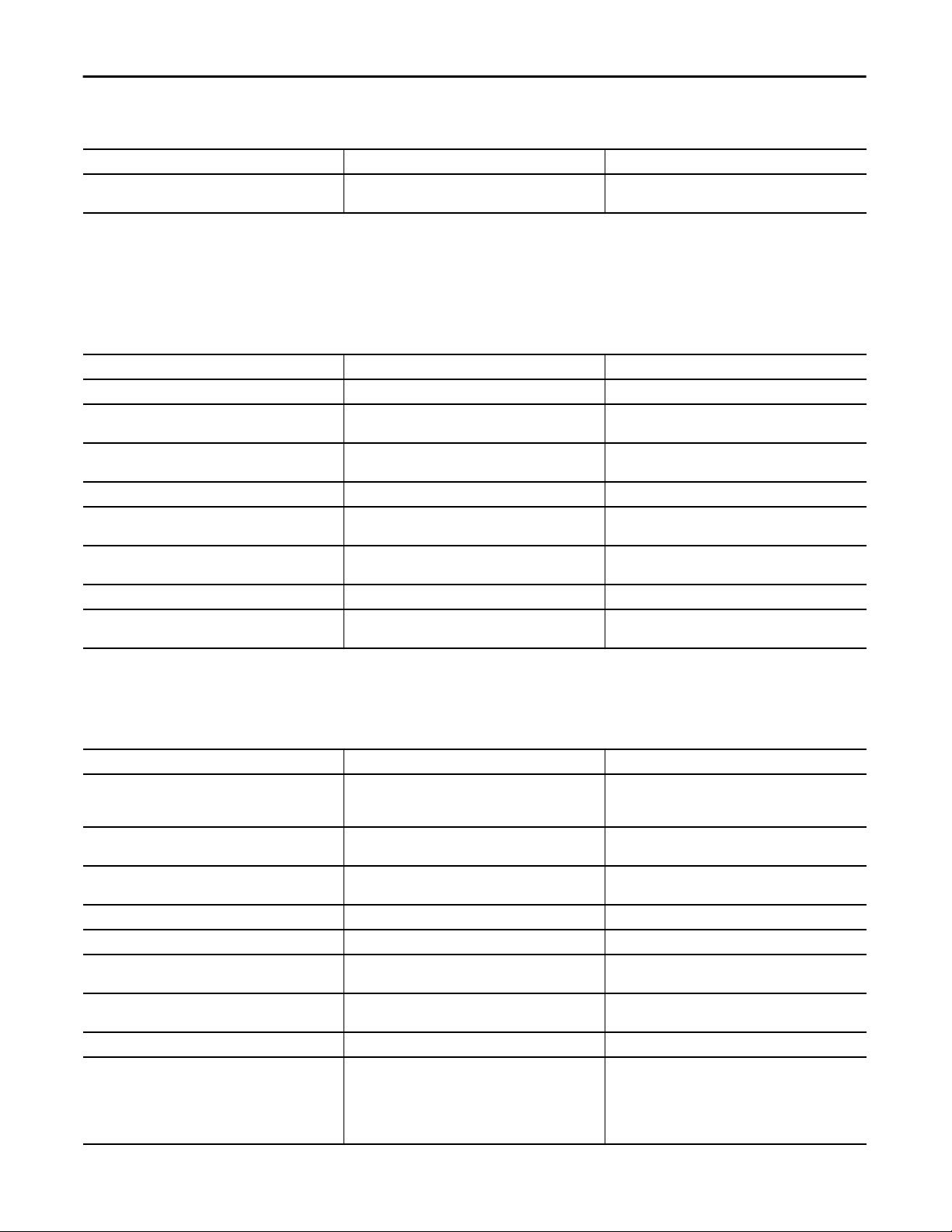
Table 1 - Summary of Changes
Topic Page
Visualization Files: Global Objects (.ggfx) - Process Diagnostic Objects 12
For the latest compatible software information and to download the Rockwell
Automation® Library of Process Objects, see the Product Compatibility and
Download Center at
http://www.rockwellautomation.com/rockwellautomation/support/pcdc.page.
For general library considerations, see Rockwell Automation Library of Process
Objects, publication
PROCES-RM002.
Rockwell Automation Publication SYSLIB-RM020G-EN-E - February 2017 5
Page 6

Preface
Additional Resources
These documents contain additional information concerning related products
from Rockwell Automation.
Resource Description
PlantPAx® Distributed Control System Selection Guide,
publication
PlantPAx Distributed Control System Reference Manual,
publication
Rockwell Automation Library of Process Objects,
publication
FactoryTalk® View Machine Edition User Manual,
publication
FactoryTalk View Site Edition User Manual,
publication
Logix5000™ Controllers Add-On Instructions
Programming Manual, publication
Rockwell Automation Library of Process Objects: Common
Alarm Block (P_Alarm) Reference Manual, publication
SYSLIB-RM002
Rockwell Automation Library of Process Objects: Common
Mode Block (P_Mode) Reference Manual, publication
SYSLIB-RM005
PROCES-SG001
PROCES-RM001
PROCES-RM002
VIEWME-UM004
VIEWSE-UM006
1756-PM010
Provides information to assist with equipment
procurement for your PlantPAx system.
Provides characterized recommendations for
implementing your PlantPAx system.
Provides general considerations for the PlantPAx system
library of process objects.
Provides details on how to use this software package for
creating an automation application.
Provides details on how to use this software package for
developing and running human-machine interface (HMI)
applications that can involve multiple users and servers,
distributed over a network.
Provides information for designing, configuring, and
programming Add-On Instructions.
Details how to monitor an input condition to raise an
alarm. Information includes acknowledging, resetting,
inhibiting, and disabling an alarm. Generally the P_Alarm
faceplate is accessible from the Alarms tab.
Explains how to choose the Mode (owner) of an
instruction or control strategy. The Mode instruction is
usually embedded within other instructions to extend
their functionality. It is possible to use a standalone Mode
instruction to enhance a program where modes are
wanted.
You can view or download publications at
http:/www.rockwellautomation.com/literature/. To order paper copies of
technical documentation, contact your local Allen-Bradley distributor or
Rockwell Automation sales representative.
6 Rockwell Automation Publication SYSLIB-RM020G-EN-E - February 2017
Page 7
Flowmeter Dosing (P_DoseFM)
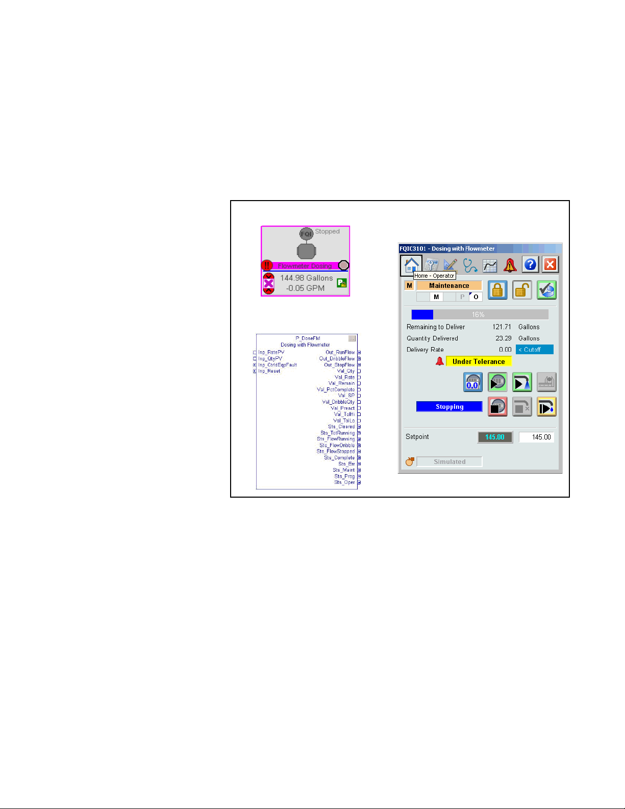
The P_DoseFM (Flowmeter Dosing) Add-On Instruction controls an
ingredient addition that uses a flowmeter to measure the quantity of ingredient
added. The flowmeter can be an analog flowmeter (signal proportional to flow), a
pulse generating flowmeter (pulse count proportional to quantity delivered), or a
digital flowmeter providing flow rate or quantity (totalized flow) information.
Global Objects
Faceplate
Add-On Instruction
Guidelines
Use this instruction in these situations:
• You want to control basic dosing (ingredient addition) with basic features,
such as bulk/dribble rate selection, preact, automatic preact adjustment,
and the ability to start, pause, and resume flow.
• You are measuring the quantity of ingredient added by using a flowmeter.
The flowmeter can provide an analog flow rate, an analog quantity (total),
or a pulse count with rollover. This instruction is designed to work well
with high-speed counting input cards, such as the 1756-HSC (High-Speed
Counter) module or the 1756-CFM (Configurable Flowmeter) module.
Rockwell Automation Publication SYSLIB-RM020G-EN-E - February 2017 7
Page 8

Flowmeter Dosing (P_DoseFM)
Do not use this instruction in these situations:
• You are transferring material by using a weigh scale to measure the quantity
of material before and after transfer. Use the P_DoseWS (Dosing with
Weigh Scale) instruction instead.
• You need to control precision blending. This instruction excludes
capability for controlled-rate addition, such as ratio control, digital
blending, or precision blending. Contact your Rockwell Automation
representative for a blending solution.
• You only need a totalizer (integrator). Use the built-in TOT instruction
instead.
You could need additional logic in these situations:
• You need more complicated sequencing, including special actions when
restarting, aborting, or holding an addition. This sequencing is a good
candidate for an equipment phase. Equipment phase logic can drive the
P_DoseFM instruction by using its Program mode commands and
settings.
• The equipment requires complicated start-up and shutdown logic. You
can provide this logic separately and use the P_DoseFM outputs to trigger
the startup and shutdown of ingredient delivery.
8 Rockwell Automation Publication SYSLIB-RM020G-EN-E - February 2017
Page 9
Flowmeter Dosing (P_DoseFM)
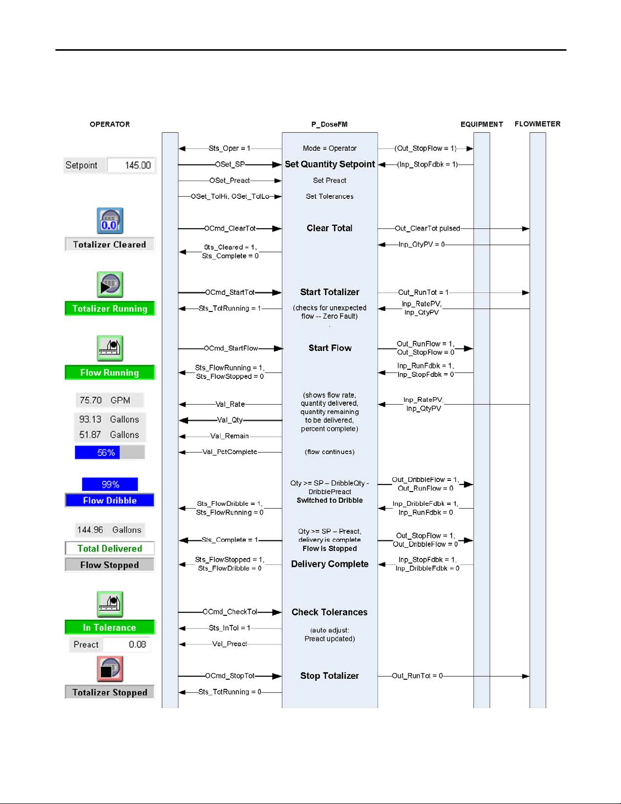
Functional Description
A typical sequence of operator commands, settings, and subsequent instruction
actions by using the P_DoseFM instruction to perform ingredient dosing in
operator mode is depicted in the following diagram.
Rockwell Automation Publication SYSLIB-RM020G-EN-E - February 2017 9
Page 10

Flowmeter Dosing (P_DoseFM)
The primary operations of the P_DoseFM instruction include the following:
• Provides inputs for rate (flow rate or quantity per time) and quantity (total
or pulse count).
• Provides the ability to use a pulse count as the Quantity PV, with
configurable rollover count.
• Provides the ability to totalize the flow rate PV to determine the
quantity delivered when the flowmeter provides a rate signal but no
quantity.
• Provides the ability to calculate the flow rate given the quantity by
differentiating with respect to time when the meter provides a total or
pulse count but no rate. If the rate PV is calculated from an input quantity,
the P_DoseFM instruction uses a first-order (lag) filter on the calculated
rate PV signal to reduce the impact of jitter, scan time, quantization error,
or input signal noise.
• Provides a low rate cutoff function, used to ignore flow rate values near
zero to deal with noise or zero calibration error in the rate signal.
• Provides the ability to use a flowmeter with built-in totalizer. Forwards the
totalizer clear command to the flowmeter and checks that the flowmeter's
total was reset. Once the total is cleared, the instruction checks for
unrequested flow; that is, an increase in the delivered total before flow is
actually started, and raises a zero fault if such flow occurs.
• Provides outputs to control associated equipment (pumps, valves, and so
forth) to start and stop flow. The operator or the program could start the
ingredient addition, then pause, and resume it if needed.
• Monitors the status of controlled equipment (pumps, valves, and so forth).
Flow is stopped and an alarm is raised on an equipment fault or if the
equipment fails to respond as commanded.
• Monitors rate and/or quantity input communication status and provides
indication of uncertain or bad rate PV or quantity PV. Flow is stopped and
an alarm is raised on a bad PV or communication loss.
• Provides program or operator entry of a quantity to deliver (setpoint) and
calculates the quantity remaining to deliver and percent complete during
delivery.
• Provides program or operator entry of high and low tolerance limits. Lets
the program or operator initiate a tolerance check after delivery is
complete. Provides a warning if under tolerance and lets the operator
bump the flow to make up the shortage. The bump can be set up as a timed
bump or as an operator jog-like function. Provides an alarm if over
tolerance and inhibits further flow.
• Includes the ability to automatically switch to a lower dribble flow rate as
the quantity delivered approaches setpoint. Provides operator or program
entry of the dribble quantity. Provides run, dribble, and stop outputs to
controlled equipment.
10 Rockwell Automation Publication SYSLIB-RM020G-EN-E - February 2017
Page 11

Flowmeter Dosing (P_DoseFM)
• Uses a preact value to stop flow to account for material in the pipe, time for
equipment to stop, and delays in measurement, scan, communication, and
so forth. Provides operator or program entry of the preact value. Provides
an optional automatic preact correction based on the error in delivery
when tolerance is checked. The auto correction lets the preact ‘learn’ the
correct value over time.
• Uses the standard mode (P_Mode) instruction to provide mode
(ownership) for entry of settings and acceptance of commands. See the
Operating Modes section for more information.
Required Files
Add-On Instructions are reusable code objects that contain encapsulated logic
that can streamline implementing your system. This lets you create your own
instruction set for programming logic as a supplement to the instruction set
provided natively in the ControlLogix® firmware. An Add-On Instruction is
defined once in each controller project, and can be instantiated multiple times in
your application code as needed.
Controller File
The P_DoseFM_3_5-00_AOI.L5X Add-On Instruction must be imported into
the controller project to be used in the controller configuration. The service
release number (boldfaced) can change as service revisions are created.
Visualization Files
This Add-On Instruction has associated visualization files that provide a
common user interface. These files can be downloaded from the Product
Compatibility and Download Center at
http://www.rockwellautomation.com/rockwellautomation/support/pcdc.page.
IMPORTANT
The visualization file dependencies require Process Library content imports to
occur in a specific order as reflected in the following tables:
• Images
• Global Objects
• Standard Displays
• HMI Tags
• Macros
Images are external graphic files that can be used in displays. They must be
imported for FactoryTalk View to make use of them.
When PNG files are imported, they are renamed by FactoryTalk View with
a .bmp file extension, but retain a .png format.
Rockwell Automation Publication SYSLIB-RM020G-EN-E - February 2017 11
Page 12
Flowmeter Dosing (P_DoseFM)
Table 2 - Visualization Files: Images (.png)
FactoryTalk View SE Software FactoryTalk View ME Software Description
All .png files in the images folder All .png files in the images folder These are the common icons used in the global objects and
standard displays for all Process Objects.
The Global Object files (.ggfx file type) in the following table are Process Library
display elements that are created once and referenced multiple times on multiple
displays in an application. When changes are made to a Global Object, all
instances in the application are automatically updated.
Table 3 - Visualization Files: Global Objects (.ggfx)
FactoryTalk View SE Software FactoryTalk View ME Software Description
(RA-BAS) Common Faceplate Objects (RA-BAS-ME) Common Faceplate Objects Global objects used on process object faceplates.
(RA-BAS) Process Alarm Objects (RA-BAS-ME) Process Alarm Objects Global objects used for managing alarms on process
(RA-BAS) Process Diagnostic Objects (RA-BAS-ME) Process Diagnostic Objects Diagnostic global objects used on process object
(RA-BAS) Process Faceplate Analog Objects (RA-BAS-ME) Process Faceplate Analog Objects Analog global objects used on process object faceplates.
(RA-BAS) Process Faceplate Misc Objects (RA-BAS-ME) Process Faceplate Misc Objects Miscellaneous global objects used on process object
(RA-BAS) Process Graphics Library (RA-BAS-ME) Process Graphics Library Process global object device symbols used to build
(RA-BAS) Process Help Objects (RA-BAS-ME) Process Help Objects Global objects used for all process objects help displays.
(RA-BAS) Process Mode Objects (RA-BAS-ME) Process Mode Objects Global objects used for managing modes on process
object faceplates.
faceplates.
faceplates.
process graphics
object faceplates.
The Standard Display files (.gfx file type) in the following table are the Process
Library displays that you see at runtime.
Table 4 - Visualization Files: Standard Displays (.gfx)
FactoryTalk View SE Software FactoryTalk View ME Software Description
(RA-BAS) Common-AnalogEdit N/A Faceplate used for analog input data entry. The FactoryTalk
(RA-BAS) P_Alarm-Faceplate (RA-BAS-ME) P_Alarm-Faceplate The faceplate that is used for managing alarms for
(RA-BAS) P_Alarm-Help (RA-BAS-ME) P_Alarm-Help Alarm Help information that is accessed from the
(RA-BAS) P_DoseFM-Faceplate (RA-BAS-ME) P_DoseFM-Faceplate The faceplate that is used for the object
(RA-BAS) P_DoseFM-Quick (RA-BAS-ME) P_DoseFM-Quick The Quick display that is used for the object
(RA-BAS) P_Mode-Config (RA-BAS-ME) P_Mode-Config The Configuration Display used to configure the
(RA-BAS) P_Mode-Help (RA-BAS-ME) P_Mode-Help Mode Help information that is accessed from the
(RA-BAS) Process Dose Family-Help (RA-BAS-ME) Process Dose Family-Help The Help display for Dose objects
(RA-BAS) P_AIChan-Faceplate (RA-BAS-ME) P_AIChan-Faceplate Optional
View ME faceplates use the native analog input data entry
so no file is required.
the object.
P_AIarm faceplate.
P_Mode object.
Help faceplate.
The Channel faceplate used for the object.
Use this file if your Analog Input has an associated
P_AIChan object and you enable navigation to its
faceplate from the Analog Input faceplate.
12 Rockwell Automation Publication SYSLIB-RM020G-EN-E - February 2017
Page 13

Table 4 - Visualization Files: Standard Displays (.gfx)
FactoryTalk View SE Software FactoryTalk View ME Software Description
(RA-BAS) P_AIChan-Help (RA-BAS-ME) P_AIChan-Help Optional
Channel Help information that is accessed from the
P_AIChan Help faceplate.
Use this file if you use the Analog Input Channel faceplate.
HMI Tags are created in a FactoryTalk View ME application to support tab
switching on Process Library faceplates. The HMI tags may be imported via the
comma-separated values file (.csv file type) in the following table.
Table 5 - Visualization Files: HMI Tags (.csv)
FactoryTalk View SE Software FactoryTalk View ME Software Description
N/A FTVME_PlantPAxLib_Tags_3_5_xx.csv
where xx = the service release number.
These tags must be imported into the
FactoryTalk View ME project to support switching tabs on
any Process Object faceplate.
Flowmeter Dosing (P_DoseFM)
Controller Code
This section describes the parameter references for this Add-On Instruction.
Flowmeter Dosing Input Structure
Input parameters include the following:
• Input data elements (Inp_) are typically used to connect field inputs from
I/O modules or signals from other objects.
• Configuration data elements (Cfg_) are used to set configurable
capabilities and features of the instruction.
• Commands (PCmd_, OCmd_, MCmd_) are used by program logic,
operators, and maintenance personnel to request instruction actions.
• Settings (PSet_, OSet_, MSet_) are used by program logic, operators, and
maintenance personnel to establish runtime setpoints, thresholds, and so
forth. A Setting (without a leading P, O, or M) establishes runtime settings
regardless of role or mode.
Rockwell Automation Publication SYSLIB-RM020G-EN-E - February 2017 13
Page 14

Flowmeter Dosing (P_DoseFM)
Table 7 - P_DoseFM Input Parameters
Input Parameter Data
Type
EnableIn BOOL 1 Ladder Diagram:
Inp_RatePV REAL 0.0 Flow rate from flowmeter (Engineering Units/time, see Cfg_RateTime).
Inp_QtyPV REAL 0.0 Quantity from flowmeter (Engineering Units or pulse count).
Inp_RunFdbk BOOL 0 1 = Controlled equipment is delivering (running).
Inp_DribbleFdbk BOOL 0 1 = Controlled equipment is delivering at dribble.
Inp_StopFdbk BOOL 0 1 = Controlled equipment is confirmed stopped.
Inp_RatePVBad BOOL 0 1 = Rate PV input quality = bad (fail).
Inp_RatePVSrcQ SINT 0 Flow rate signal source and quality (enumeration).
Inp_RatePVUncertain BOOL 0 1 = Rate PV input quality = uncertain.
Inp_QtyPVBad BOOL 0 1 = Quantity PV input quality = bad (fail).
Inp_QtyPVSrcQ SINT 0 Quantity signal source and quality (enumeration).
Inp_QtyPVUncertain BOOL 0 1 = Quantity PV input quality = uncertain.
Inp_CtrldEqpFault BOOL 0 Controlled equipment device or I/O status:
Inp_Sim BOOL 0 Simulation input. When set to 1, the instruction simulates a working dosing
Inp_Reset BOOL 0 Input parameter used to programmatically reset alarms. When set to 1, all
Cfg_HasDribble BOOL 0 1 = Slow to dribble before complete.
Cfg_HasEqpFdbk BOOL 0 1 = Controlled equipment provides run, dribble (if used) and stop feedback.
Cfg_UseEqpFdbk BOOL 0 1 = Use run/dribble/stop feedback.
Cfg_AutoAdjPreact BOOL 0 1 = Enable automatic adjustment of preact after each tolerance check.
Cfg_CalcRate BOOL 0 1 = Differentiate Inp_Qty to get rate.
Cfg_CalcQty BOOL 0 1 = Integrate Inp_Rate to get quantity.
Cfg_SetTrack BOOL 1 This parameter is used to set up bumpless behavior of setting parameters
Alias For Default Description
If the rung-in condition is true, the instruction’s Logic routine executes. If the
rung-in condition is false, the instruction’s EnableInFalse routine executes.
Function Block Diagram:
If true, or not connected, the instruction’s Logic routine executes. If the
parameter is exposed as a pin and wired, and the pin is false, the instruction’s
EnableInFalse routine executes.
Structured Text:
No effect. The instruction’s Logic routine executes.
0 = OK
1 = Fail
action. When set to 0, the instruction controls dosing normally.
alarms requiring reset are reset.
0 = Run full flow until complete.
0 = Assume equipment state.
0 = Use Inp_Rate.
0 = Use Inp_Qty.
when switching modes. When this parameter is 1, in Program mode the
operator settings track the program settings; in Operator mode the program
settings track the operator settings; and the simulation inputs match the
output values (transitions are bumpless).
When this parameter is 0, the operator settings and program settings are not
modified by this instruction. In this case, when the mode is changed, the
effective value of the setting can change depending on the program-set and
operator-set values.
14 Rockwell Automation Publication SYSLIB-RM020G-EN-E - February 2017
Page 15
Table 7 - P_DoseFM Input Parameters
Flowmeter Dosing (P_DoseFM)
Input Parameter Data
Type
Cfg_HasChanObjRate BOOL 0 1 = Tells HMI a Channel object (P_AIChan, and so forth) is used for
Cfg_HasChanObjQty BOOL 0 1 = Tells HMI a Channel object (P_AIChan, and so forth) is used for Inp_QtyPV.
Cfg_PCmdClear BOOL Mode.Cfg_PCmdClear 1 When this parameter is 1, program commands are cleared once they are acted
Cfg_ProgDefault BOOL Mode.Cfg_ProgDefault 0 This parameter defines the default mode. When this parameter is 1, the mode
Cfg_ShedOnEqpFault BOOL 0 1 = Stop delivery and alarm on equipment fault.
Cfg_HasOverTolAlm BOOL OverTol.Cfg_Exists 0 These parameters determine whether the corresponding alarm exists and is
Cfg_HasUnderTolAlm UnderTol.Cfg_Exists
Cfg_HasZeroFaultAlm ZeroFault.Cfg_Exists
Cfg_HasEqpFaultAlm EqpFault.Cfg_Exists
Cfg_OverTolResetReqd BOOL OverTol.Cfg_ResetReqd 0 These parameters determine whether a reset is required to clear the alarm
Cfg_UnderTolResetReqd UnderTol.Cfg_ResetReqd
Cfg_ZeroFaultResetReqd ZeroFault.Cfg_ResetReqd
Cfg_EqpFaultResetReqd EqpFault.Cfg_ResetReqd
Cfg_OverTolAckReqd BOOL OverTol.Cfg_AckReqd 1 These parameters determine whether an acknowledgement is required for an
Cfg_UnderTolAckReqd UnderTol.Cfg_AckReqd 1
Cfg_ZeroFaultAckReqd ZeroFault.Cfg_AckReqd 1
Cfg_EqpFaultAckReqd EqpFault.Cfg_AckReqd 1
Cfg_OverTolSeverity INT OverTol.Cfg_Severity 750 These parameters determine the severity of each alarm. This drives the color
Cfg_UnderTolSeverity UnderTol.Cfg_Severity 500
Cfg_ZeroFaultSeverity ZeroFault.Cfg_Severity 1000
Cfg_EqpFaultSeverity EqpFault.Cfg_Severity 1000
Cfg_MaxQty REAL 1.00E+38 Maximum allowed quantity to deliver (setpoint) (engineering units).
Alias For Default Description
Inp_RatePV.
IMPORTANT: The name of the Channel Rate object in the controller must be
this object's name with the suffix ‘_ChanRate’. For example, if your P_DoseFM
object has the name ‘DoseFM123’, then its Channel Rate object must be named
‘DoseFM123_ChanRate’.
IMPORTANT: The name of the Channel Quantity object in the controller must
be this object's name with the suffix ‘_ChanQty’. For example, if your
P_DoseFM object has the name ‘DoseFM123’, then its Channel Quantity object
must be named ‘DoseFM123_ChanQty’.
upon. When set to 0, program commands remain set until cleared by the
application program logic.
IMPORTANT: Clearing this parameter online can cause unintended program
command execution.
defaults to Program if no mode is being requested. When this parameter is 0,
the mode defaults to Operator if no mode is being requested.
IMPORTANT: Changing this parameter online can cause unintended mode
changes.
0 = Alarm only on equipment fault.
checked or if the alarm does not exist and is not used. When these parameters
are 1, the corresponding alarm exists.
status. When these parameters are 1, the alarm is latched ON when the alarm
occurs. After the alarm condition returns to normal, a reset is required to clear
the alarm status (for example, OCmd_Reset, Inp_Reset, or
EqpFault.OCmd_Reset are required to clear Alm_EqpFault alarm after the
alarm is set and the equipment returns to normal).
When these parameters are 0, no reset is required and the alarm status is
cleared when the alarm condition returns to normal.
IMPORTANT: If the reset clears the alarm, it also acknowledges the alarm.
alarm. When these parameters are 1, the acknowledge (ack) bit is cleared
when the alarm occurs. An acknowledge command (for example,
PCmd_EqpFaultAck or EqpFault.OCmd_Ack) is required to acknowledge the
alarm. When set to 0, the Acknowledge bit is set when an alarm occurs
indicating an acknowledged alarm and no acknowledge command is required.
and symbols that are used to indicate alarm status on the faceplate and global
object.
The following are valid values:
1…250 = Low
251…500 = Medium
501…750 = High
751…1000 = Urgent
IMPORTANT: For FactoryTalk View software version 7.0, these severity
parameters drive only the indication on the global object and faceplate. The
Alarms & Events definition severity drives the color and symbol that is used on
the alarm banner and alarm summary as well as the value returned by
FactoryTalk Alarms & Events display commands.
Rockwell Automation Publication SYSLIB-RM020G-EN-E - February 2017 15
Page 16
Flowmeter Dosing (P_DoseFM)
Table 7 - P_DoseFM Input Parameters
Input Parameter Data
Type
Cfg_EUQtyMult REAL 1.0 Rate to quantity engineering units multiplier (for example, gallons to barrels.).
Cfg_Rollover REAL 0.0 Quantity rollover (for example, maximum count for pulse input).
Cfg_CountsPerEU REAL 1.0 Number of counts in Inp_QtyPV that equal 1.0 engineering units.
Cfg_RateTime REAL 1.0 Time factor for rate (60.0 for engineering units/minute, 3600.0 for engineering
Cfg_RateFiltTC REAL 0.1 Filter time constant (seconds) for calculated rate.
Cfg_LoRateCutoff REAL 0.0 Rate below which to report zero flow (Inp_RatePV units).
Cfg_SettleT REAL 1.0 Time to allow flow to stop before allowing tolerance check (seconds).
Cfg_BumpT REAL 0.0 Bump (manual top-off ) time (seconds), 0.0 = use Bump command as a ‘jog’.
Cfg_AutoAdjPct REAL 10.0 Percentage of delivery error to auto-adjust preact (%).
Cfg_SimRate REAL 1.0 Rate at which to deliver when running in simulation (engineering units/rate
Cfg_SimDribbleRate REAL 0.1 Rate at which to dribble when running in simulation (engineering units/rate
Cfg_ClearPulseT DINT 1 Time to pulse Out_Clear to clear external totalizer (seconds).
Cfg_FaultT DINT 10 Time for equipment feedback to follow output before fault (seconds).
Cfg_OperKeep SINT 2#0000_0000 Operator keeps control in Program mode:
Cfg_ProgKeep SINT 2#0000_0000 Program keeps control in Operator mode:
PSet_SP REAL 0.0 Program setting of total quantity to deliver (engineering units).
PSet_DribbleQty Program setting of quantity to dribble (engineering units).
PSet_Preact Program setting of quantity before total to stop flow (engineering units).
PSet_TolHi Program setting of high tolerance threshold (OK quantity > SP).
PSet_TolLo Program setting of low tolerance threshold (OK quantity < SP).
PSet_Owner DINT 0 Program owner request ID (non-zero) or release (zero).
OSet_SP REAL 0.0 Operator setting of total quantity to deliver (engineering units).
OSet_DribbleQty Operator setting of quantity to dribble (engineering units).
OSet_Preact Operator setting of quantity before total to stop flow (engineering units).
OSet_TolHi Operator setting of high tolerance threshold (OK quantity > SP).
OSet_TolLo Operator setting of low tolerance threshold (OK quantity < SP).
Alias For Default Description
units/hour) (in seconds).
time).
time).
Bit .0 = Operator keeps Start/stop
Bit .1 = Operator keeps Setpoint
Bit .2 = Operator keeps Dribble/preact
Bit .3 = Operator keeps Tolerances
Bit .0 = Program keeps Start/stop
Bit .1 = Program keeps Setpoint
Bit .2 = Program keeps Dribble/preact
Bit .3 = Program keeps Tolerances
16 Rockwell Automation Publication SYSLIB-RM020G-EN-E - February 2017
Page 17
Table 7 - P_DoseFM Input Parameters
Flowmeter Dosing (P_DoseFM)
Input Parameter Data
PCmd_ClearTot BOOL 0 When Cfg_PCmdClear is 1:
PCmd_StartTot
PCmd_StopTot
PCmd_StartFlow BOOL 0 When Cfg_PCmdClear is 1:
PCmd_StopFlow
PCmd_CheckTol
PCmd_Bump BOOL 0 When PCmd_Bump is set to 1:
PCmd_Acq BOOL
PCmd_Rel Mode.PCmd_Rel
PCmd_Lock BOOL
PCmd_Unlock Mode.PCmd_Unlock
PCmd_Reset BOOL 0 • Set PCmd_Reset to 1 to reset all alarms requiring reset
PCmd_OverTolAck BOOL OverTol.PCmd_Ack 0 • Set PCmd_<Alarm>Ack to 1 to Acknowledge alarm
PCmd_UnderTolAck UnderTol.PCmd_Ack
PCmd_ZeroFaultAck ZeroFault.PCmd_Ack
PCmd_EqpFaultAck EqpFault.PCmd_Ack
Type
BOOL
BOOL
Alias For Default Description
• Set PCmd_ClearTot to 1 to clear the totalizer quantity
• Set PCmd_StartTot to 1 to start the totalizer
• Set PCmd_StopTot to 1 to stop the totalizer
• These parameters reset automatically
When Cfg_PCmdClear is 0:
• Set PCmd_ClearTot to 1 to clear the totalizer quantity
• Set PCmd_StartTot to 1 to start the totalizer
• Set PCmd_StopTot to 1 to stop the totalizer
• These parameters do not reset automatically
• Set PCmd_StartFlow to 1 to start delivery
• Set PCmd_StopFlow to 1 to stop delivery
• Set PCmd_CheckTolerances to 1 to check tolerances
• These parameters reset automatically
When Cfg_PCmdClear is 0:
• Set PCmd_StartFlow to 1 to start delivery
• Set PCmd_StopFlow to 1 to stop delivery
• Set PCmd_CheckTolerances to 1 to check tolerances
• These parameters do not reset automatically
• If the configured bump time (Cfg_BumpT) is nonzero, then bump delivery
for the configured bump time
– PCmd_Bump is cleared automatically
• If the configured bump time (Cfg_BumpT) is zero, then bump delivery until
PCmd_Bump is returned to 0
– PCmd_Bump is not cleared automatically
• Cfg_PCmdClear is not affected by this parameter
Mode.PCmd_Acq 0
0
Mode.PCmd_Lock 0
0
When Cfg_PCmdClear is 1:
• Set PCmd_Acq to 1 to Acquire
• Set PCmd_Rel to 1 to Release
• These parameters reset automatically
When Cfg_PCmdClear is 0:
• Set PCmd_Acq to 1 to Acquire
• Set PCmd_Acq to 0 to Release
• PCmd_Rel is not used
• These parameters do not reset automatically
When Cfg_PCmdClear is 1:
• Set PCmd_Lock to 1 to Lock
• Set PCmd_Unlock to 1 to Unlock
• These parameters reset automatically
When Cfg_PCmdClear is 0:
• Set PCmd_Lock to 1 to Lock
• Set PCmd_Lock to 0 to Unlock
• PCmd_Unlock is not used
• These parameters do not reset automatically
• This parameter is always reset automatically
• T
he par
ameter is reset automatically
Rockwell Automation Publication SYSLIB-RM020G-EN-E - February 2017 17
Page 18

Flowmeter Dosing (P_DoseFM)
Table 7 - P_DoseFM Input Parameters
Input Parameter Data
Type
PCmd_OverTolSuppress BOOL OverTol.PCmd_Suppress 0 When Cfg_PCmdClear is 1:
PCmd_UnderTolSuppress UnderTol.PCmd_Suppress
PCmd_ZeroFaultSuppress ZeroFault.PCmd_Suppress
PCmd_EqpFaultSuppress EqpFault.PCmd_Suppress
PCmd_OverTolUnsuppress BOOL OverTol.PCmd_Unsuppress 0
PCmd_UnderTolUnsuppress UnderTol.PCmd_Unsuppress
PCmd_ZeroFaultUnsuppress ZeroFault.PCmd_Unsuppress
PCmd_EqpFaultUnsuppress EqpFault.PCmd_Unsuppress
PCmd_OverTolUnshelve BOOL OverTol.PCmd_Unshelve • Set PCmd_<Alarm>Unshelve to 1 to Unshelve alarm
PCmd_UnderTolUnshelve UnderTol.PCmd_Unshelve
PCmd_ZeroFaultUnshelve ZeroFault.PCmd_Unshelve
PCmd_EqpFaultUnshelve EqpFault.PCmd_Unshelve
OCmd_ClearTot BOOL 0 Operator commands to clear totalizer quantity, start totalizer, or stop totalizer.
OCmd_StartTot
OCmd_StopTot
OCmd_StartFlow BOOL 0 Operator commands to start delivery, stop/pause delivery, or check tolerances.
OCmd_StopFlow
OCmd_CheckTol
OCmd_Bump BOOL 0 Operator command to bump delivery for under tolerance.
MCmd_Acq BOOL Mode.MCmd_Acq 0 Maintenance command to acquire ownership (Operator/Program/Override to
MCmd_Rel BOOL Mode.MCmd_Rel 0 Maintenance command to release ownership (Maintenance to Operator/
OCmd_AcqLock BOOL Mode.OCmd_AcqLock 0 Operator command to acquire and lock mode in Operator.
OCmd_Unlock BOOL Mode.OCmd_UnlockRel 0 Operator command to unlock Operator mode.
OCmd_Reset BOOL 0 Operator command to reset all alarms requiring reset.
OCmd_ResetAckAll BOOL 0 Operator command to acknowledge and reset all alarms and latched shed
Alias For Default Description
• Set PCmd_<Alarm>Suppress to 1 to suppress alarm
• Set PCmd_<Alarm>Unsuppress to 1 to unsuppress alarm
• These parameters reset automatically
When Cfg_PCmdClear is 0:
• Set PCmd_<Alarm>Suppress to 1 to suppress alarm
• Set PCmd_<Alarm>Suppress to 0 to unsuppress alarm
• PCmd_<Alarm>Unsuppress is not used
• These Parameters do not reset automatically
• The parameter is reset automatically
Maintenance)
Program/Override)
conditions.
18 Rockwell Automation Publication SYSLIB-RM020G-EN-E - February 2017
Page 19

Table 8 - P_DoseFM Output Parameters
Flowmeter Dosing (P_DoseFM)
Flowmeter Dosing Output Structure
Output parameters include the following:
• Output data elements (Out_) are the primary outputs of the instruction,
typically used by hardware output modules; however, they can be used by
other application logic.
• Value data elements (Val_) are numeric outputs of the instruction for use
by the HMI. Values can also be used by other application logic or software
packages.
• Source and Quality data elements (SrcQ_) are outputs of the instruction
used by the HMI to indicate PV source and quality.
• Status data elements (Sts_) are bit outputs of the instruction for use by the
HMI. Status bits can also be used by other application logic.
• Error data elements (Err_) are outputs of the instruction that indicate a
particular configuration error. If any Err_ bit is set, then the Sts_Err
configuration error summary status is set and the Invalid Configuration
indicator is displayed on the HMI.
• Not Ready data elements (Nrdy_) are bit outputs of the instruction for use
by the HMI for displaying the Device Not Ready indicator. Not Ready bits
can also be used by other application logic.
• Alarm data elements (Alm_) are outputs of the instruction that indicate a
particular alarm has occurred.
• Acknowledge data elements (Ack_) are outputs of the instruction that
indicate the corresponding alarm has been acknowledged.
• Ready data elements (Rdy_) are bit outputs of the instruction used by the
HMI to enable or disable Command buttons and Setting entry fields.
Output Parameter Data Type Alias For Description
EnableOut BOOL Enable Output: The EnableOut signal is not manipulated by this instruction. Its output state
Out_RunFlow BOOL 1 = Deliver at full (fast) flow.
Out_DribbleFlow BOOL 1 = Deliver at dribble (slow) flow.
Out_StopFlow BOOL 1 = Stop delivery equipment.
Out_RunTot BOOL 1 = Run external totalizer (for example, onboard flowmeter).
Out_ClearTot BOOL 1 = Reset external totalizer (for example, onboard flowmeter).
Val_Qty REAL Quantity actually delivered (totalizer output) (engineering units).
Val_Rate REAL Current delivery rate (engineering units/time) (see Cfg_RateTime).
Val_Remain REAL Quantity yet to deliver to reach setpoint (engineering units).
Val_PctComplete REAL Percent complete (for progress bar on HMI) 0.0…100.0%.
Val_SP REAL Quantity to be delivered (setpoint) (engineering units).
Val_DribbleQty REAL Quantity to be delivered at slow rate (engineering units).
Val_Preact REAL Quantity before SP at which flow is be stopped (engineering units).
Val_TolHi REAL Allowed quantity > SP (engineering units).
Val_TolLo REAL Allowed quantity < SP (engineering units).
always reflects EnableIn Input state.
Rockwell Automation Publication SYSLIB-RM020G-EN-E - February 2017 19
Page 20

Flowmeter Dosing (P_DoseFM)
Table 8 - P_DoseFM Output Parameters
Output Parameter Data Type Alias For Description
SrcQ_IO SINT I/O signal source and quality.
SrcQ Final dose source and quality.
GOOD 0 = I/O live and confirmed good quality
1 = I/O live and assumed good quality
2 = No feedback configured, assumed good quality
TEST 8 = Device simulated
9 = Device loopback simulation
10 = Manually entered value
UNCERTAIN 16 = Live input, off-specification
17 = Value substituted at device/bus
18 = Value substituted by maintenance (Has and not Use)
19 = Shed, using last good value
20 = Shed, using replacement value
BAD 32 = Signal failure (out-of-range, NaN, invalid combination)
33 = I/O channel fault
34 = I/O module fault
35 = Bad I/O configuration (for example, scaling parameters)
Val_Cmd SINT This shows the command being processed, returns to zero once the command succeeds or fails.
Val_Fdbk SINT This shows the feedback input from the device:
Val_Sts SINT This is the primary status, used to show the operator the confirmed device status:
Val_Fault SINT This is the device fault status, used to show the operator the most severe device fault:
Val_Mode SINT Mode.Val This shows the current mode of the object:
Val_Owner DINT Current object owner ID (0 = not owned).
These values are also used for Inp_OvrdCmd:
0 = None
1 = Clear totalizer
2 = Start totalizer
3 = Start delivery
4 = Start dribble
5 = Bump
6 = Stop delivery
7 = Stop totalizer
0 = None
1 = Stopped
2 = Delivering
3 = Dribbling
0 = Power up/reset
1 = Stopped
2 = Totalizing
3 = Delivering
4 = Dribbling
5 = Bumping
6 = Start delivery
7 = Start dribble
8 = Stopping
33 = Disabled
0 = None
17 = Equipment fault
34 = Configuration error
0 = No mode
2 = Maintenance
4 = Program lock
5 = Operator lock
6 = Program (operator default)
7 = Operator (program default)
8 = Program (program default)
9 = Operator (operator default)
20 Rockwell Automation Publication SYSLIB-RM020G-EN-E - February 2017
Page 21

Flowmeter Dosing (P_DoseFM)
Table 8 - P_DoseFM Output Parameters
Output Parameter Data Type Alias For Description
Val_Notify SINT Current alarm level and acknowledgement (enumeration):
0 = No alarm
1 = Alarm cleared: a reset or acknowledge is required
2 = Low (acknowledged)
3 = Low (unacknowledged)
4 = Medium (acknowledged)
5 = Medium (unacknowledged)
6 = High (acknowledged)
7 = High (unacknowledged)
8 = Urgent (acknowledged)
9 = Urgent (unacknowledged)
Sts_Cleared BOOL 1 = Totalizer clear completed.
Sts_TotRunning BOOL 1 = Totalizer running.
Sts_FlowStarting BOOL 1 = Flow is starting (Out_Run is on, feedback not showing run).
Sts_FlowRunning BOOL 1 = Flow is running (Out_Run is on), feedback showing run.
Sts_DribbleStarting BOOL 1 = Dribble starting (Out_Dribble is on, feedback not showing dribble).
Sts_FlowDribble BOOL 1 = Flow is slowed to dribble (Out_Dribble is on), feedback showing dribble.
Sts_FlowStopping BOOL 1 = Flow is stopping (Out_Stop is on, feedback not showing stopped).
Sts_FlowStopped BOOL 1 = Flow is stopped (Out_Stop is on), feedback showing stopped.
Sts_Bumping BOOL 1 = Bump flow is active.
Sts_LoRateCutoff BOOL 1 = Rate PV below low rate cutoff, flow assumed to be zero.
Sts_Complete BOOL 1 = Total delivered > (SP - preact).
Sts_InTol BOOL 1 = Total delivered is within tolerances.
Sts_Available BOOL 1 = Dosing available for control by automation (Program).
Sts_QtyBad BOOL 1 = Quantity value is bad (PV fail).
Sts_QtyUncertain BOOL 1 = Quantity value is uncertain.
Sts_RateBad BOOL 1 = Rate value is bad (PV fail).
Sts_RateUncertain BOOL 1 = Rate value is uncertain.
Sts_NotRdy BOOL 1 = Device is not ready to be operated.
Nrdy_CfgErr BOOL 1 = Device Not Ready:
Nrdy_PVBad
Nrdy_EqpFault
Nrdy_NoMode
Sts_MaintByp BOOL 1 = A maintenance bypass is active, display icon.
Sts_AlmInh BOOL 1 = One or more alarms shelved, disabled, or suppressed.
Sts_Err BOOL 1 = Error: Bad Configuration, see detail Err bits for reason.
Err_EU BOOL 1 = Error: Cfg_CountsPerEU, Cfg_EUQtyMult or Cfg_Rollover invalid.
Err_Rate BOOL 1 = Error: Cfg_RateFiltTC or Cfg_RateTime invalid.
Err_Cutoff BOOL 1 = Error: Cfg_LoRateCutoff invalid.
Err_Limit BOOL 1 = Error: Cfg_MaxQty invalid.
Err_Sim BOOL 1 = Error: Cfg_SimDribbleRate or Cfg_SimRate invalid.
Err_Timer BOOL 1 = Error: Cfg_BumpT or Cfg_ClearPulseT (use 0.0…2,147,483.647).
0 = Totalizer stopped.
• Configuration Error
• PV Bad Quality or Comm Failure
• External equipment fault (Fault or Shed Requires Reset)
• Device logic disabled/no mode
Rockwell Automation Publication SYSLIB-RM020G-EN-E - February 2017 21
Page 22

Flowmeter Dosing (P_DoseFM)
Table 8 - P_DoseFM Output Parameters
Output Parameter Data Type Alias For Description
Err_Alarm BOOL 1 = Error: Alarm minimum on time or severity invalid.
Sts_Maint BOOL Mode.Sts_Maint 1 = Mode is maintenance (supersedes override, program, operator).
Sts_Prog BOOL Mode.Sts_Prog 1 = Mode is program (auto).
Sts_Oper BOOL Mode.Sts_Oper 1 = Mode is operator (manual).
Sts_ProgOperLock BOOL Mode.Sts_ProgOperLock 1 = Program or operator has requested mode lock.
Sts_NoMode BOOL Mode.Sts_NoMode 1 = NoMode (disabled because EnableIn is false).
Sts_MAcqRcvd BOOL Mode.Sts_MAcqRcvd 1 = Maintenance acquire command received this scan.
Sts_OverTol BOOL OverTol.Inp 1 = Delivery out of tolerance high (excess).
Sts_UnderTol UnderTol.Inp 1 = Delivery out of tolerance low (short).
Sts_ZeroFault ZeroFault.Inp 1 = Total did not clear or unexpected flow.
Sts_EqpFault EqpFault.Inp 1 = Equipment fault detected.
Alm_OverTol BOOL OverTol.Alm 1 = Delivery out of tolerance high (excess) alarm.
Alm_UnderTol UnderTol.Alm 1 = Delivery out of tolerance low (short) alarm.
Alm_ZeroFault ZeroFault.Alm 1 = Warning: Total did not clear or still flowing.
Alm_EqpFault EqpFault.Alm 1 = Alarm: Equipment fault (sensor or controlled equipment).
Ack_OverTol BOOL OverTol.Ack 1 = Over Tolerance, Under Tolerance, Zero Fault, or Equipment fault alarm acknowledged.
Ack_UnderTol UnderTol.Ack
Ack_ZeroFault ZeroFault.Ack
Ack_EqpFault EqpFault.Ack
Sts_OverTolDisabled BOOL OverTol.Disabled 1 = Over Tolerance, Under Tolerance, Zero fault, or Equipment Fault alarm disabled by
Sts_UnderTolDisabled UnderTol.Disabled
Sts_ZeroFaultDisabled ZeroFault.Disabled
Sts_EqpFaultDisabled EqpFault.Disabled
Sts_OverTolShelved BOOL OverTol.Shelved 1 = Over Tolerance, Under Tolerance, Zero Fault, or Equipment Fault alarm shelved by Operator.
Sts_UnderTolShelved UnderTol.Shelved
Sts_ZeroFaultShelved ZeroFault.Shelved
Sts_EqpFaultShelved EqpFault.Shelved
Sts_OverTolSuppressed BOOL OverTol.Suppressed 1 = Over Tolerance, Under Tolerance, Zero Fault, or Equipment Fault alarm suppressed by
Sts_UnderTolSuppressed UnderTol.Suppressed
Sts_ZeroFaultSuppressed ZeroFault.Suppressed
Sts_EqpFaultSuppressed EqpFault.Suppressed
Rdy_ClearTot BOOL 1 = Ready for OCmd to clear, start, or stop Totalizer (enables HMI button).
Rdy_StartTot
Rdy_StopTot
Rdy_StartFlow BOOL 1 = Ready for OCmd StartFlow, StopFlow, or CheckTol (enables HMI button).
Rdy_StopFlow
Rdy_CheckTol
Rdy_Bump BOOL 1 = Ready for OCmd_Bump (enables HMI button).
Maintenance.
Program.
22 Rockwell Automation Publication SYSLIB-RM020G-EN-E - February 2017
Page 23

Flowmeter Dosing (P_DoseFM)
Table 8 - P_DoseFM Output Parameters
Output Parameter Data Type Alias For Description
Rdy_Reset BOOL 1 = Ready for OCmd to Reset or Reset and Acknowledge All alarms (enables HMI button).
Rdy_ResetAckAll
Rdy_SP BOOL 1 = Ready to receive OSet_SP.
Rdy_DribPre BOOL 1 = Ready to receive OSet_DribbleQty or OSet_Preact.
Rdy_Tol BOOL 1 = Ready to receive OSet_TolHi or Oset_TolLo.
P_DoseFM BOOL Unique parameter name for auto-discovery.
Flowmeter Dosing Local Configuration Tags
Configuration parameters that are arrayed, string, or structure data types cannot
be configured as parameters for Add-On Instructions. Configuration parameters
of these types appear as local tags to the Add-On Instruction. Local tags can be
configured through the HMI faceplates or in Studio 5000 Logix Designer®
application by opening the Instruction Logic of the Add-On Instruction instance
and then opening the Data Monitor on a local tag. These parameters cannot be
modified by using controller logic or Logix Designer application export/import
functionality.
Table 9 - P_DoseFM Local Configuration Tags
Tag Name Data Type Default Description
Cfg_Desc STRING_40 ‘Dosing with Flowmeter’ Description for display on HMI. This string is shown in the title bar of the faceplate.
Cfg_Label STRING_20 ‘Flowmeter dosing’ Label for graphic symbol displayed on HMI. This string appears on the graphic symbol.
Cfg_Tag STRING_20 ‘P_DoseFM’ Tag name for display on HMI. This string is shown in the title bar of the faceplate.
Cfg_QtyEU STRING_8 ‘kg’ Engineering units for quantity for display on HMI.
Cfg_RateEU STRING_8 ‘kg/sec’ Engineering units for rate (flow) for display on HMI.
Operations
This section describes the primary operations for Add-On Instructions.
Modes
This instruction uses the following standard modes, which are implemented by
using an embedded P_Mode Add-On Instruction.
Table 10 - Modes
Mode Description
Operator The Operator owns control of the device. Operator commands (OCmd_) and Operator settings
Program Program logic owns control of the device. Program commands (PCmd_) and Program settings
(OSet_) from the HMI are accepted.
(PSet_) are accepted.
Rockwell Automation Publication SYSLIB-RM020G-EN-E - February 2017 23
Page 24

Flowmeter Dosing (P_DoseFM)
Table 10 - Modes
Mode Description
Maintenance Maintenance owns control of the device and supersedes Operator, Program, and Override
control. Operator commands and settings from the HMI are accepted. Bypassable interlocks and
permissives are bypassed, and device timeout checks are not processed.
No Mode The device is disabled and has no owner because the EnableIn input is false. The main
instruction Logic routine is not being scanned. See Execution section for more information on
EnableInFalse processing.
IMPORTANT
Instructions with Cfg_OperKeep and Cfg_ProgKeep keep some aspects of the
device operation with the operator or program regardless of whether the main
mode is Program or Operator mode.
The following standard modes are not used:
• Hand mode
• Override (Ovrd) mode
See Rockwell Automation Library of Process Objects: Common Mode Block
(P_Mode) Reference Manual, publication
SYSLIB-RM005, for more
information.
Alarms
This instruction uses the following alarms, which are implemented by using
embedded P_Alarm and P_Gate Add-On Instructions.
Alarm Name P_Alarm Name P_Gate Name Description
Equipment Fault EqpFault None Raised when the Inp_CtrldEqpFault input is true, or
Over tolerance OverTol None Raised when the tolerance check is performed and the
Under Tolerance
(Warning)
Zero fault ZeroFault None Raised if the totalizer fails to clear, or if the totalizer is
UnderTol None Raised when the tolerance check is performed and the
when equipment feedback signals fail to track the
commanded state of the equipment within the
configured time. If an equipment fault is configured
as a shed fault, the flow is stopped and a reset is
required to resume flow.
quantity delivered exceeds the setpoint by more than
the High Tolerance threshold.
quantity delivered falls short of the setpoint by more
than the Low Tolerance threshold.
TIP: In some instances, the Bump function can be
used to make up the shortage.
cleared but then registers flow before flow is
commanded to start.
Parameters of the P_Alarm object can be accessed by using the following
convention: [P_Alarm Name].[P_Alarm Parameter].
24 Rockwell Automation Publication SYSLIB-RM020G-EN-E - February 2017
Page 25

Flowmeter Dosing (P_DoseFM)
See Rockwell Automation Library of Process Objects: Common Alarm Block
(P_Alarm) Reference Manual, publication
SYSLIB-RM002, for more
information.
Simulation
When the P_DoseFM block is placed in simulation, it continues to generate its
outputs to control equipment, but the flow quantity and rate inputs are ignored
and a simulated flow rate is used.
This operation in simulation is different from the equipment (motor, valve,
drive) instructions.
WARNING: To avoid starting equipment during simulation, the downstream
equipment instructions must be put in simulation so that their outputs are held
in the SAFE state.
Failure to do this can result in personal injury or equipment damage.
Set the Inp_Sim parameter to ‘1’ to enable simulation.
The Simulation Test icon is displayed at the bottom left of the Operator
faceplate to indicate the instruction is in simulation.
While in simulation, you can use the following parameters to control how the
flow is simulated:
• Cfg_SimRate – the full rate to be used for delivery (in flow units/rate
time)
• Cfg_SimDribbleRate – the rate to be used for dribble (in flow units/rate
time)
When you have finished simulation, clear the Inp_Sim parameter to 0 to return
to normal operation.
Rockwell Automation Publication SYSLIB-RM020G-EN-E - February 2017 25
Page 26

Flowmeter Dosing (P_DoseFM)
Execution
The following table explains the handling of instruction execution conditions.
Condition Description
EnableIn False (false rung) Any commands received are discarded. All alarms are
Powerup (prescan, first scan) Any commands received before first scan are discarded.
Postscan (SFC transition) No SFC postscan logic is provided.
See the Logix5000 Controllers Add-On Instructions Programming Manual,
publication
1756-PM010, for more information.
cleared. The mode is reported as No Mode. The displayed
rate is zeroed. Outputs to controlled equipment are deenergized. Other output parameters (values and status)
hold their last value.
Embedded P_Alarm instructions are handled in
accordance with their standard powerup procedures.
Refer to the reference manual for the P_Alarm
instructions for more information.
26 Rockwell Automation Publication SYSLIB-RM020G-EN-E - February 2017
Page 27
Flowmeter Dosing (P_DoseFM)
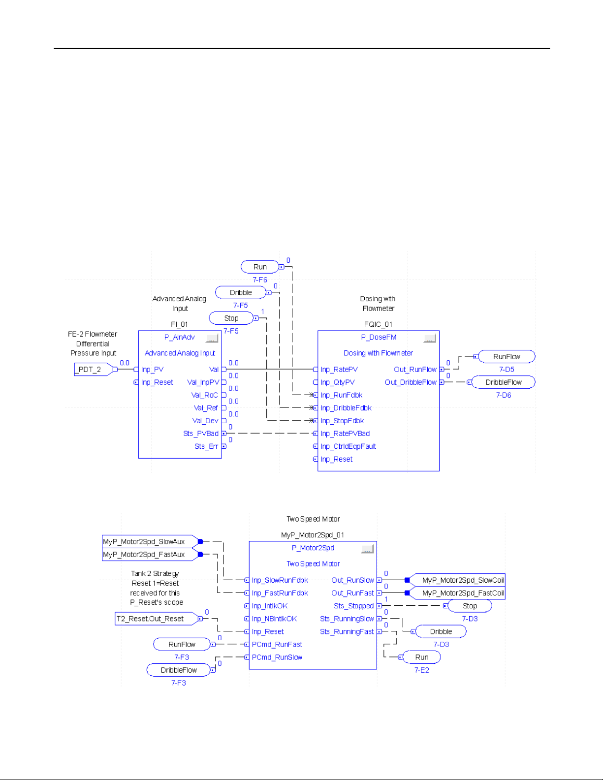
Programming Example
The example for P_DoseFM shows an input from a flowmeter (I_PDT_2)
connected to a P_AInAdv block for the conversion of differential pressure to
flow.
The PV representing flow (Val from P_AInAdv) is taken as the input for
P_DoseFM (Inp_RatePV). The Sts_PVBad for the flow value is also used by
P_DoseFM (Inp_RatePVBad). The outputs of P_DoseFM (Out_RunFlow and
Out_DribbleFLow) are used as inputs to a two-speed motor (P_Motor2Spd).
RunFlow and DribbleFlow are connected to PCmd_RunFast and
PCmd_RunSlow, respectively. The status outputs of the motor for stopped
(Sts_Stopped), running slow (Sts_RunningSlow), and running fast
(Sts_RunningFast) are connected back to the P_DoseFM block as inputs
Inp_StopFdbk, Inp_DribbleFdbk, and Inp_RunFdbk.
Rockwell Automation Publication SYSLIB-RM020G-EN-E - February 2017 27
Page 28

Flowmeter Dosing (P_DoseFM)
Display Elements
A display element (global object) is created once and can be referenced multiple
times on multiple displays in an application. When changes are made to the
original (base) object, the instantiated copies (reference objects) are
automatically updated. Use of global objects, in conjunction with tag structures
in the ControlLogix system, aid consistency and save engineering time.
Table 11 - P_DoseFM Display Elements Description
Display Element Name Display Element Description
GO_DoseFM Vertical Orientation Top
GO_DoseFM1 Vertical Orientation Bottom
GO_DoseFM2 Horizontal Orientation Right
GO_DoseFM3 Horizontal Orientation Left
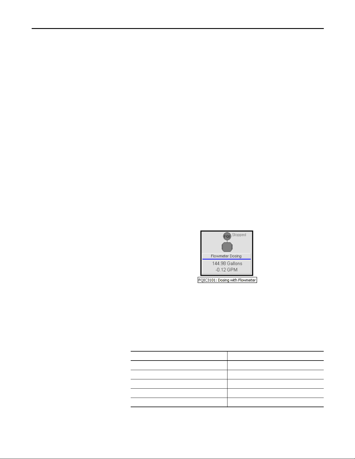
Graphic objects are provided for use on end-user process graphic displays.
Flowmeter dosing graphic objects have the following common attributes.
Label
Alarm Border
Alarm Indicator
Status/Quality
Indicators
Quantity and
Rate Value
Totalizer Symbol
Quantity and Rate
Engineering Units
Totalizer State Text
Flowmeter Symbol
Status/Quality Indicator
Progress Bar
(percent complete)
Mode Indicator
28 Rockwell Automation Publication SYSLIB-RM020G-EN-E - February 2017
Page 29
Flowmeter Dosing (P_DoseFM)
Common attributes of the P_DoseFM graphic symbols include the following:
• Graphical representation of the device
• Maintenance Bypass indicator
• Status/quality indicator
• Mode indicators
• Quantity and Rate values
• Label
• Flowmeter and Totalizer Symbols
• Totalizer State text
• Progress bar (percent complete)
• Quantity and Rate Engineering Units
• Color changing alarm border that blinks on unacknowledged alarm
• Alarm indicator that changes color for the severity of the alarm
Each flowmeter dosing graphic symbol displays the object’s label and engineering
units text, the current value of the flow rate and quantity delivered in this dosing,
and various status indicators. The graphic symbol has a color changing alarm
border that blinks on unacknowledged alarm.
The overall graphic symbol includes a touch field over it that opens the object’s
faceplate. In addition, pausing the pointing device over the graphic symbol
displays a tooltip showing the object’s configured tag and description.
Graphic Representation
The label displays change color based on the highest severity alarm currently
active.
Table 12 - Alarm Severity Colors
Color Alarm Severity
Light blue Low
Yellow Medium
Red High
Magenta Urgent
Gray No active alarms
Rockwell Automation Publication SYSLIB-RM020G-EN-E - February 2017 29
Page 30
Flowmeter Dosing (P_DoseFM)
The color of the flowmeter symbol changes depending on the commanded state
of the controlled equipment.
Table 13 - Flowmeter State Colors
Color Flowmeter State
Dark Gray No flow (stopped)
White Running
Blue Dribble
Light Blue Bumping
The color of the totalizer (FQI) symbol changes depending on the current state
of totalizing.
Table 14 - Totalizer State Colors
Color Totalizer State
Dark Gray Stopped
White Running
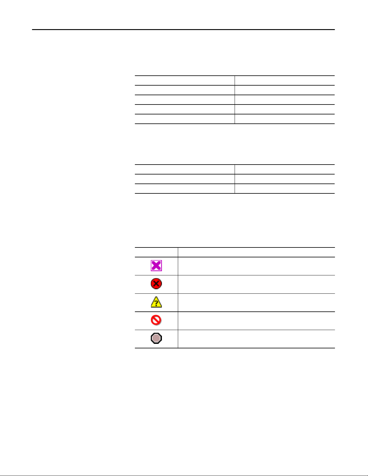
Status/Quality Indicators
One of these symbols appears on the graphic symbol when the described
condition is true.
Graphic Symbol Description
Invalid configuration.
Data quality bad/failure.
Data Quality degraded: uncertain, test, simulation, substitution, or out of specification.
The input or device has been disabled.
Device not ready to operate.
TIP
When the Invalid Configuration indicator appears, you can find what
configuration setting is invalid by following the indicators. Click the graphic
symbol to open the faceplate. The Invalid Configuration indicator appears next
to the appropriate tab at the top of the faceplate to guide you in finding the
configuration error. Once you navigate to the tab, the misconfigured item is
flagged with this indicator or appears in a magenta box.
For the P_DoseFM instruction, the Invalid Configuration indicator appears
under any of the following conditions:
30 Rockwell Automation Publication SYSLIB-RM020G-EN-E - February 2017
Page 31

Flowmeter Dosing (P_DoseFM)
• Counts per Engineering Unit value is less than or equal to zero.
• Engineering Unit Quantity Multiplier value is less than or equal to zero.
• Quantity Rollover Count value is less than zero.
• Rate Filter Time Constant value is less than zero.
• Rate Time value is less than or equal to zero.
• Low Rate Cutoff value is less than zero.
• Maximum Allowed Quantity Setpoint value is less than or equal to zero.
• Simulation Flow Rate or Simulation Dribble Rate value is less than or
equal to zero.
• Settle Time, Bump Time, Clear Pulse Time, or Equipment Fault Check
Time is set to a value less than zero or greater than 2,147,483 seconds.
• Alarm Minimum On Time is set to a value less than zero or greater than
2,147,483 seconds.
• Alarm Severity is set to a value less than 1 or greater than 1000.
TIP
When the Not Ready indicator appears, you can find what condition is
preventing operation by following the indicators. Click the graphic symbol to
open the faceplate. The Not Ready indicator appears next to the appropriate
tab at the top of the faceplate to guide you in finding the condition. When you
navigate to the tab, the condition preventing operation is flagged.
For the Flowmeter Dosing instruction, the Device Not Ready indicator appears
under the following conditions:
• There is a configuration error.
• PV is of bad quality or there is a communication failure.
• There is an external equipment fault and shed requires reset.
Device logic is disabled or there is no mode.
Mode Indicators
One of these symbols appears on the right side of the graphic symbol to indicate
the mode of the object instruction.
Graphic Symbol Description
Transparent Operator mode (if the default mode is Operator and the current mode is Operator, the mode
indicator is transparent).
Operator mode (if the default mode is Program).
Operator mode locked.
Transparent Program mode (if the default mode is Program and the current mode is Program, the mode
Rockwell Automation Publication SYSLIB-RM020G-EN-E - February 2017 31
indicator is transparent).
Program mode (if the default mode is Operator).
Page 32

Flowmeter Dosing (P_DoseFM)
Graphic Symbol Description
Program mode locked.
Maintenance mode.
No mode.
TIP
The images provided for the Operator and Program default modes are
transparent; therefore, no mode indicators are visible if the device is in its
default mode. This behavior can be changed by replacing the image files for
these mode indicators with images that are not transparent.
See Rockwell Automation Library of Process Objects: Common Mode Block
(P_Mode) Reference Manual, publication
SYSLIB-RM005, for more
information.
Alarm Indicators
One of these symbols appears on the left side of the label to indicate the described
alarm condition and the alarm border and label background change color. The
alarm border and label background blink if acknowledgement of an alarm
condition is required. Once the alarm is acknowledged, the alarm border and
label background remain the color that corresponds to the severity of the alarm.
Symbol Border and Label Background Description
No change in color Alarm Inhibit: an alarm is suppressed by the Program,
White Return to normal (no alarm condition), but a previous
disabled by Maintenance, or shelved by the Operator.
alarm has not been acknowledged.
Blue Low severity alarm.
Yellow Medium severity alarm.
Red High severity alarm.
Magenta Urgent severity alarm.
No symbol No change in color No alarm or alarm inhibit condition, and all alarms
are acknowledged.
See Rockwell Automation Library of Process Objects: Common Alarm Block
(P_Alarm) Reference Manual, publication
information.
32 Rockwell Automation Publication SYSLIB-RM020G-EN-E - February 2017
SYSLIB-RM002, for more
Page 33

Flowmeter Dosing (P_DoseFM)
Maintenance Bypass Indicator
This symbol appears to the right of the label to indicate that a maintenance
bypass has been activated.
TIP
When the Maintenance Bypass indicator appears, you can find what condition
was bypassed by following the indicators. Click the graphic symbol to open the
faceplate. The Maintenance Bypass indicator appears next to the appropriate
tab at the top of the faceplate to guide you in finding the bypass. Once you
navigate to the tab, the bypassed item is flagged with
this indicator.
For this instruction, the Maintenance Bypass indicator appears when the
instruction is configured by Engineering to have equipment feedback, but
Maintenance has selected not to use the equipment feedback.
Rockwell Automation Publication SYSLIB-RM020G-EN-E - February 2017 33
Page 34

Flowmeter Dosing (P_DoseFM)
Using Display Elements
The global objects for P_DoseFM can be found in the global object file
(RA-BAS) Process Graphics Library.ggfx. Follow these steps to use a global
object.
1. Copy the global object from the global object file and paste it in the
display file.
2. In the display, right-click the global object and choose Global Object
Parameter Values.
The Global Object Parameter Values dialog box appears.
34 Rockwell Automation Publication SYSLIB-RM020G-EN-E - February 2017
Page 35

Flowmeter Dosing (P_DoseFM)
The global object parameters are as follows:
Table 15 - Global Object Parameter Values
Parameter Required Description
#102 Y Object tag to point to the name of the associated object Add-On
#103 Y Path used for display navigation features to other objects. Include
#120 N Additional parameter to pass to the display command to open the
#121 N Additional parameter to pass to the display command to open the
#122 Y These are the options for the global object display:
Instruction in the controller.
program scope if tag is a program scope tag.
faceplate. Typically used to define position for the faceplate.
faceplate. If defining X and Y coordinate, separate parameters so
that X is defined by #120 and Y is defined by #121. This lets these
same parameters be used in subsequent display commands
originating from the faceplate.
0 = Always show faceplate
1 = Show Quick Display for users without Maintenance access
(Code C)
2 = Always show Quick Display
3. In the Value column, type the tag or value as specified in the Description
column.
TIP
Click the ellipsis (…) to browse and select a tag.
Values for items marked ‘(optional)’ can be left blank.
4. Click OK.
Rockwell Automation Publication SYSLIB-RM020G-EN-E - February 2017 35
Page 36

Flowmeter Dosing (P_DoseFM)
Quick Display
The Quick Display screen provides means for operators to perform simple
interactions with the P_DoseFM instruction instance. From the Quick Display,
you can navigate to the faceplate for full access.
Navigate to Full
Faceplate Button
Faceplate
The P_DoseFM faceplate consists of six tabs and each tab consists of one or more
pages.
The title bar of each faceplate contains the value of local configuration tags
Cfg_Tag and Cfg_Desc.
The Operator tab is displayed when the faceplate is initially opened. Click the
appropriate icon at the top of the faceplate to access a specific tab.
Maintenance
Operator Engineering
HelpTrends
ExitDiagnostics Alarms
The faceplate provides the means for operators, maintenance personnel,
engineers, and others to interact with the P_DoseFM instruction instance,
including viewing its status and values and manipulating it through its commands
and settings. When a given input is restricted via FactoryTalk View security, the
required user security code letter is shown in the tables that follow.
36 Rockwell Automation Publication SYSLIB-RM020G-EN-E - February 2017
Page 37

Flowmeter Dosing (P_DoseFM)
Operator Tab
The Faceplate initially opens to the Operator (‘Home’) tab. From here, an
operator can monitor the device status and manually operate the device when it is
in Operator mode.
The Operator tab shows the following information:
• Current mode (Operator, Program, or Maintenance).
• Requested modes indicator (appears only if the Operator or Program
mode has been superseded by another mode; see the Maintenance tab
section for more information).
• Totalizer progress bar if totalizing or the totalizer status (cleared, complete,
or complete at zero).
• Quantity remaining to deliver display.
• Quantity delivered display.
• Delivery rate display.
• Low rate cutoff indicator. (Appears only if the flow quantity is calculated
by totalizing a rate input and the rate is less than the low rate cutoff
configuration value Cfg_LoRateCutoff. When this indicator appears, the
flow rate is assumed to be zero for totalizing and the quantity holds its
value.)
• Tolerance check result indicator (in tolerance, over tolerance, or under
tolerance; this appears after performing a tolerance check).
• Equipment commanded state indicator (for example, stopped, running,
dribble, or bumping).
• Quantity setpoint data entry field.
• Input Source and Quality indicator (See 'SrcQ' in the Output parameters
table on
page 20 for details).
Rockwell Automation Publication SYSLIB-RM020G-EN-E - February 2017 37
Page 38

Flowmeter Dosing (P_DoseFM)
• Alarm status indicators appear next to values or status indicators that are in
alarm.
Operator Mode
Command Buttons
Mode Indicator
Requested
Mode Indicator
Delivery
Progress Bar
Tolerance Indicator
Clear Totalized
Quantity Button
Dosing Equipment
Commanded State
Stop Totalizer
Button
Input Source and
Quality Indicator
Input Source and
Quality Icon
Reset and Acknowledge
All Alarms Button
Totalizer Low Rate
Cutoff Indicator
Start Totalizer Button
Start/Resume Flow Button
Check Tolerance Button
Bump Flow Button
Stop Flow Button
TIP
The Tolerance Indicator shows if the delivery was in tolerance, under tolerance
or over tolerance. This indicator is visible only when a tolerance check has been
requested after delivery is stopped or complete.
If a delivery is under tolerance (short) and the bump function is enabled, the
operator can bump the equipment to try to make up the shortfall and bring
the delivery into tolerance.
38 Rockwell Automation Publication SYSLIB-RM020G-EN-E - February 2017
Page 39

Flowmeter Dosing (P_DoseFM)
The following table shows the functions that are included on the Operator tab.
Table 16 - Operator Tab Description
Function Action Security
Click to lock in Operator mode. Function locks the mode in
Operator mode, preventing the program from taking control.
Click to unlock Operator mode. Function unlocks Operator
mode, letting the program to take control.
Click to request Program mode.
Click to request Operator mode.
Manual Device
Operation (Code B)
Click to reset and acknowledge all alarms. Acknowledge Alarms
Click to clear the totalized quantity. Normal Operation of
Click to start Totalizer.
Click to stop Totalizer.
Click to start or resume delivery.
Click to stop (pause) delivery.
Click to perform a tolerance check on the delivered quantity.
(Code F)
Devices (Code A
Click to bump flow. This function is used to top off a delivery
that has passed the preact point but is still short of the
setpoint quantity.
Setpoint quantity Configure the quantity to deliver.
Rockwell Automation Publication SYSLIB-RM020G-EN-E - February 2017 39
Page 40

Flowmeter Dosing (P_DoseFM)
Alarm indicators appear on the Operator tab when the corresponding alarm
occurs.
Zero Fault Alarm
Over Tolerance Alarm
Under Tolerance Alarm
Equipment Fault Alarm
The following table shows the alarm status symbols that are used on the Operator
tab.
Table 17 - Operator Tab Alarm Status
Graphic Symbol Alarm Status
In Alarm (Active Alarm).
In Alarm and Acknowledged.
Out of Alarm but not Acknowledged.
Alarm Suppressed (by Operator) (Alarm is logged but not displayed).
Alarm Disabled (by Maintenance).
Alarm Shelved (by Program Logic).
40 Rockwell Automation Publication SYSLIB-RM020G-EN-E - February 2017
Page 41

Flowmeter Dosing (P_DoseFM)
Maintenance Tab
Maintenance personnel use the information and controls on the Maintenance tab
to make adjustments to device parameters, troubleshoot and temporarily work
around device problems, and disable the device for routine maintenance.
The Maintenance tab is divided into two pages.
Maintenance Tab Page 1
Page 1 of the Maintenance tab shows the following information:
• Current mode (Operator, Program, or Maintenance)
• Requested modes indicator highlights all modes that have been requested,
and the leftmost highlighted mode is the active mode
• Dribble quantity data entry field.
• Preact quantity data entry field
• Current high tolerance value
• Current low tolerance value
Mode Indicator
Requested Modes
Indicator
Input Signals from
Flowmeter
Maintenance Mode Acquire and
Release Command Buttons
Rockwell Automation Publication SYSLIB-RM020G-EN-E - February 2017 41
Page 42

Flowmeter Dosing (P_DoseFM)
The following table shows the functions on page 1 of the Maintenance tab.
Table 18 - Maintenance Tab Page 1 Descriptions
Function Action Security Configuration Parameters
Click for Maintenance mode. Equipment
Maintenance
(Code C)
Click to release Maintenance mode.
None
Input signals from
Flowmeter
Dribble Quantity Configure the quantity before the end of
Preact Quantity Configure the quantity before reaching the
Delivery Tolerance
over Setpoint
Delivery Tolerance
below Setpoint
Use Equipment
Feedback
Bumpless Program/
Operator Transition
Click 'Raw Quantity Input' or 'Raw Rate Input'
to open the corresponding channel object’s
faceplate.
IMPORTANT: See
more information on relationships to these
functions.
delivery, when a switch to a reduced flow
rate (dribble) for finer control of the final
quantity is made.
Setpoint Quantity when a command the
delivery equipment to stop to allow
equipment to react. This helps prevent
overshooting the delivery Setpoint.
Type the quantity by which delivery can
exceed the setpoint. If the delivered quantity
is more than the setpoint plus this value, a
tolerance check shows over tolerance.
Type the quantity by which delivery can fall
short of the setpoint. If the delivered
quantity is less than the setpoint minus this
value, a tolerance check shows under
tolerance.
Check to use the available feedback from the
delivery equipment and take the device out
of Maintenance Feedback.
Clear this checkbox to not use feedback from
the delivery equipment and place the device
in Maintenance Feedback.
IMPORTANT: 'Delivery Equipment has
Feedback' on page 2 of the Engineering tab
must be enabled for this field to be visible.
Check to enable bumpless Program/Operator
transition of Quantity Setpoint, Dribble
Quantity, Preact, and Tolerance Threshold
settings (tracking).
Table 21 on page 47 for
Normal
Operation of
Devices
(Code A)
Cfg_UseEqpFdbk
Cfg_SetTrack
42 Rockwell Automation Publication SYSLIB-RM020G-EN-E - February 2017
Page 43

Maintenance Tab Page 2
Flowmeter Dosing (P_DoseFM)
The following table lists the functions on page 2 of the Maintenance tab.
Table 19 - Maintenance Tab Page 2 Descriptions
Function Action Security Configuration Parameters
Rate below which to
report zero flow
Percentage of delivery
error to auto-adjust
preact (%)
Type a value so that when the flow
rate is less than this value, it is
treated as zero. This prevents
totalizing the transmitter error when
flow is stopped.
Type the percentage of delivery error.
When the delivery tolerance is
checked, if no bump has occurred and
if the delivery is in tolerance, the
error (difference between delivery
setpoint and actual delivery) is
multiplied by this percentage and
applied to the preact. This lets the
preact self-tune and learn the correct
value of the preact over time.
Configuration
and Tuning
maintenance
(Code D)
Cfg_LoRateCutoff
Cfg_AutoAdjPct
Rockwell Automation Publication SYSLIB-RM020G-EN-E - February 2017 43
Page 44

Flowmeter Dosing (P_DoseFM)
Table 19 - Maintenance Tab Page 2 Descriptions
Function Action Security Configuration Parameters
Time to Pulse Clear
Output to clear totalizer
(seconds)
Duration of flow when
the Bump button is
pressed
Time for Equipment
Feedback before Fault
(seconds)
Delay after flow stop
before enabling
tolerance check
(seconds)
Configure the Time (in seconds) to
Pulse the Clear Output to clear an
external totalizer, such as one in an
intelligent flowmeter.
Type the amount of time to
command the controlled equipment
to run flow when the bump
command button is pressed. If this
value is set to zero, Bump is treated
like a Jog: flow starts when the
button is pressed and stops when the
button is released. If this value is
greater than zero, flow is bumped for
the configured time.
Type the maximum allowed feedback
time.
If equipment feedback is being used,
the instruction allows this much time
after commanding the equipment for
feedback to show the equipment in
the commanded state before raising
a fault status.
Type the amount of time in seconds
after flow is stopped for the scale
reading to settle before a tolerance
check can be commanded.
Configuration
and Tuning
maintenance
(Code D)
Cfg_ClearPulseT
Cfg_BumpT
Cfg_FaultT
Cfg_SettleT
44 Rockwell Automation Publication SYSLIB-RM020G-EN-E - February 2017
Page 45

Flowmeter Dosing (P_DoseFM)
Engineering Tab
The Engineering tab provides access to device configuration parameters and
ranges, options for device and I/O setup, displayed text, and
faceplate-to-faceplate navigation settings, for initial system commissioning or
later system changes.
The Engineering tab is divided into four pages.
Engineering Tab Page 1
Page 1 of the Engineering tab lets you configure the description, label, tag, and
PV units for the device.
Mode Configuration Button
Configure Device
Description, Label, and
Tag
Configure Quantity and
Rate Units of Measure Text
Rockwell Automation Publication SYSLIB-RM020G-EN-E - February 2017 45
Page 46

Flowmeter Dosing (P_DoseFM)
The following table lists the functions on page 1 of the Engineering tab.
Table 20 - Engineering Tab Page 1 Descriptions
Function Action Security Configuration Parameters
Click to navigate to the Mode
Configuration Display.
Engineering
Configuration
(Code E)
See Mode Configuration
page 47
Display on
Description Type the device description to be used
Label Type the device label to be used on the
Tag Type the tagname to be used on the title
Quantity Units Type the units of measure descriptor for
Rate Units Type the units of measure descriptor for
Auto adjust Preact after
each delivery
Integrate Inp_Rate to
get Quantity
Differentiate Inp_Qty to
get Rate
Slow to Dribble before
Complete
Clear Program
commands on Receipt
on the Faceplate title bar.
Graphic Symbol.
bar of the Faceplate and in the Tooltip.
the Quantity delivered.
the Rate of delivery.
Check to automatically adjust the Preact
based on the actual versus setpoint
Quantity after each successful delivery.
Clear this checkbox to leave the Preact as
entered.
Check if the flowmeter provides a Rate
input but no Quantity input. The Rate is
totalized (integrated) to calculate
Quantity.
IMPORTANT: See
for more information on availability of
this function.
Check if the flowmeter provides a
Quantity input but no Rate input. The
rate of change in the Quantity is used as
the Rate.
IMPORTANT: See Table 21 on page 47
for more information on availability of
this function.
Check to have the equipment
commanded to a slower Dribble rate as
delivery nears completion to improve
the accuracy of Quantity delivered.
Check to clear Program commands on
Receipt.
Table 21 on page 47
Cfg_Desc
Cfg_Label
Cfg_Tag
Cfg_QtyEU
Cfg_RateEU
Cfg_AutoAdjPreact
Cfg_CalcQty
Cfg_CalcRate
Cfg_HasDribble
Cfg_PCmdClear
46 Rockwell Automation Publication SYSLIB-RM020G-EN-E - February 2017
Page 47

Table 21 - Quantity/Rate Relationships
Flowmeter Dosing (P_DoseFM)
The following table shows the relationships between the following functions:
• Integrate Rate to Get Quantity
• Differentiate Quantity to Get Rate
• Enable Navigation to Quantity Input Object
• Enable Navigation to rate Input Object
• Raw Quantity Input
• Raw Rate Input
Integrate Rate to Get
Quantity
See Engineering Tab Page 1 on page 45 See Engineering Tab Page 2 on page 48 See Maintenance Tab Page 1 on page 41
Off Off Available Available Used for quantity Used for rate
On Off Not Available Available Not used Used for rate and quantity
Off On Available Not Available Used for rate and quantity Not used
On On Do not use this configuration.
Differentiate Quantity
to Get Rate
Enable Navigation to
Quantity Input Object
Enable Navigation to
Rate Input Object
Raw Quantity Input Raw Rate Input
Mode Configuration Display
This display lets you set the Cfg_ProgDefault parameter which sets the default
mode when no mode is being requested. Changing the parameter requires
engineering access (security code E).
IMPORTANT
If no mode is being requested, changing the default mode changes the mode
of the instruction.
Rockwell Automation Publication SYSLIB-RM020G-EN-E - February 2017 47
Page 48

Flowmeter Dosing (P_DoseFM)
Engineering Tab Page 2
The following table shows the functions on page 2 of the Engineering tab.
Table 22 - Engineering Tab Page 2 Descriptions
Function Action Security Configuration Parameters
Delivery equipment
has feedback
Check if the controlled equipment
provides feedback of its running,
dribbling, and stopped status to this
instruction. This instruction checks
that the equipment is performing the
commanded function and provides a
status (and optional alarm) if the
equipment fails to respond as
commanded within a configurable
time.
IMPORTANT: The feedback fault
time is configured on page 2 of the
Maintenance tab.
Clear this checkbox if the controlled
equipment does not provide
feedback of its status. The instruction
assumes the equipment is
performing the commanded function
and no equipment failure-to-respond
checking occurs.
Engineering
configuration
(code E)
Cfg_HasEqpFdbk
48 Rockwell Automation Publication SYSLIB-RM020G-EN-E - February 2017
Page 49

Flowmeter Dosing (P_DoseFM)
Table 22 - Engineering Tab Page 2 Descriptions
Function Action Security Configuration Parameters
Stop delivery on
equipment fault
Enable navigation
to Quantity Input
object
Enable navigation
to Rate Input object
Maximum allowed
quantity to deliver
(setpoint)
Number of counts
in Inp_QtyPV that
equal one
engineering unit
Integrated Rate to
quantity
engineering units
multiplier (for
example, Gallons to
Barrels)
Quantity rollover
(total counts for
pulse input)
Check if you want the dosing
instruction to attempt to stop the
controlled equipment if an
equipment fault is reported
(Inp_CtrldEqupFault) or detected (via
feedbacks).
Clear this checkbox if you want the
dosing instruction to keep
performing its current function, even
if an equipment fault occurs.
Check to enable navigation to the
quantity input’s channel object
faceplate.
IMPORTANT: See
page 47 for more information on
availability of this function.
Navigation is accomplished by
clicking the raw quantity input on
page 1 of the Maintenance tab.
IMPORTANT: The name of the
Channel Quantity object in the
controller must be this object's name
with the suffix ‘_ChanQty’. For
example, if your P_DoseFM object
has the name ‘DoseFM123’, then its
Channel Quantity object must be
named ‘DoseFM123_ChanQty’.
Check to enable navigation to the
rate input’s channel object faceplate.
IMPORTANT: See
page 47 for more information on
availability of this function.
Navigation is accomplished by
clicking the raw rate input on page 1
of the Maintenance tab.
IMPORTANT: The name of the
Channel Rate object in the controller
must be this object's name with the
suffix ‘_ChanRate’. For example, if
your P_DoseFM object has the name
‘DoseFM123’, then its Channel Rate
object must be named
‘DoseFM123_ChanRate’.
Type the maximum allowed quantity
to deliver. The quantity setpoint is
clamped to not exceed this value.
Type the number of counts in
Inp_QtyPV that equal one
engineering unit of quantity
delivered. This value is used with
pulse output flowmeters and a pulse
input I/O card.
Type the rate to quantity engineering
units multiplier. This value is used if
the input is in one unit of measure,
such as gallons per minute, and the
total is in another that requires
conversion above and beyond time
units, such as barrels.
Type the quantity rollover. This value
is used when a quantity or pulse
count input rolls over to zero at some
value, such as 999,999 counts.
Table 21 on
Table 21 on
Engineering
configuration
(code E)
Cfg_ShedOnEqpFault
Cfg_HasChanObjQty
Cfg_HasChanObjRate
Cfg_MaxQty
Cfg_CountsPerEU
Cfg_EUQtyMult
Cfg_Rollover
Rockwell Automation Publication SYSLIB-RM020G-EN-E - February 2017 49
Page 50

Flowmeter Dosing (P_DoseFM)
Engineering Tab Page 3
The following table lists the functions on Page 3 of the Engineering tab.
Table 23 - Engineering Tab Page 3 Descriptions
Function Action Security Configuration Parameters
Filter time constant
for calculated rate
Time factor for rate Type the time factor for rate. If the
Start & stop
commands operator keeps
control in Program
mode
Type the filter time constant for
calculated rate.
rate is in units per second, enter 1.0; if
the rate is in units per minute, enter
60.0; and so on.
Check to keep control of dosing
commands (start totalizer, start flow,
and so forth) with the operator, even
if the instruction is in Program mode.
Clear this checkbox to have control of
dosing commands that follow the
instruction mode.
Engineering
configuration
(code E)
Cfg_RateFiltTC
Cfg_RateTime
Cfg_OperKeep.0
50 Rockwell Automation Publication SYSLIB-RM020G-EN-E - February 2017
Page 51

Flowmeter Dosing (P_DoseFM)
Table 23 - Engineering Tab Page 3 Descriptions
Function Action Security Configuration Parameters
Start & stop
commands Program keeps
control in Operator
mode
Setpoint - Operator
keeps control in
Program mode
Setpoint - Program
keeps control in
Operator mode
Dribble & preact
settings - Operator
keeps control in
Program mode
Dribble & preact
settings - Program
keeps control in
Operator mode
High/low
tolerances Operator keeps
control in Program
mode
High/low
tolerances Program keeps
control in Operator
mode
Check to keep control of dosing
commands (start totalizer, start flow,
and so forth) with the program, even
if the instruction is in Operator mode.
Clear this checkbox to have control of
dosing commands that follow the
instruction mode.
Check to keep control of the setpoint
quantity setting with the operator,
even if the instruction is in Program
mode.
Clear this checkbox to have control of
the setpoint quantity setting that
follow the instruction mode.
Check to keep control of the setpoint
quantity setting with the program,
even if the instruction is in Operator
mode.
Clear this checkbox to have control of
the setpoint quantity setting that
follow the instruction mode.
Check to keep control of the dribble
and preact quantity settings with the
operator, even if the instruction is in
Program mode.
Clear this checkbox to have control of
the dribble and preact quantity
settings that follow the instruction
mode.
Check to keep control of the dribble
and preact quantity settings with the
program, even if the instruction is in
Operator mode.
Clear this checkbox to have control of
the dribble and preact quantity
settings that follow the instruction
mode.
Check to keep control of the high and
low tolerance settings with the
operator, even if the instruction is in
Program mode.
Clear this checkbox to have control of
the high and low tolerance settings
that follow the instruction mode.
Check to keep control of the high and
low tolerance settings with the
program, even if the instruction is in
Operator mode.
Clear this checkbox to have control of
the high and low tolerance settings
that follow the instruction mode.
Engineering
configuration
(code E)
Cfg_ProgKeep.0
Cfg_OperKeep.1
Cfg_ProgKeep.1
Cfg_OperKeep.2
Cfg_ProgKeep.2
Cfg_OperKeep.3
Cfg_ProgKeep.3
Rockwell Automation Publication SYSLIB-RM020G-EN-E - February 2017 51
Page 52

Flowmeter Dosing (P_DoseFM)
Engineering Tab Page 4
Page 4 of the Engineering tab lets you type the Delivery rate and the Dribble rate
in simulation.
Table 24 - Engineering Tab Page 4 Descriptions
Function Action Security Configuration Parameters
Delivery rate in
Loopback Test
(GPM)
Dribble rate in
Loopback Test
(GPM)
52 Rockwell Automation Publication SYSLIB-RM020G-EN-E - February 2017
Type the normal running delivery rate that is
used when the P_DoseFM instruction is in
simulation (Inp_Sim = 1).
Type the dribble (slow) delivery rate that is
used when the P_DoseFM instruction is in
simulation (Inp_Sim = 1).
Engineering
configuration
(code E)
Cfg_SimRate
Cfg_SimDribbleRate
Page 53

Flowmeter Dosing (P_DoseFM)
Diagnostics Tab
The Diagnostic tab provides indications that are helpful in diagnosing or
preventing device problems, which can include specific reasons a device is 'Not
Ready', device warnings and faults, warning and fault history, and predictive/
preventive maintenance data.
The Diagnostics tab displays possible reasons the device is not ready.
The previous image indicates that there is an external equipment fault and it
requires a reset.
Rockwell Automation Publication SYSLIB-RM020G-EN-E - February 2017 53
Page 54

Flowmeter Dosing (P_DoseFM)
Trends Tab
The Trends Tab shows trend charts of key device data over time. These faceplate
trends provide a quick view of current device performance to supplement, but not
replace, dedicated historical or live trend displays.
The Trends tab is divided into two pages.
Trends Tab Page 1
(Green) Rate
54 Rockwell Automation Publication SYSLIB-RM020G-EN-E - February 2017
Page 55

(Blue) Setpoint
(Green) Quantity
Flowmeter Dosing (P_DoseFM)
Trends Tab Page 2
Rockwell Automation Publication SYSLIB-RM020G-EN-E - February 2017 55
Page 56

Flowmeter Dosing (P_DoseFM)
Device Not
Ready Indicator
Alarm Names
Alarms Tab
The Alarms Tab shows all available alarms for the device and their current status.
From here, Alarms can be acknowledged and reset. Click an alarm to open the
alarm detail faceplate for that alarm, where the alarm can be shelved by the
operator, disabled by maintenance personnel, or configured by engineering.
Alarms Tab
Alarm Severity
Indicators
Alarm Acknowledge
Command Button
Reset and
Acknowledge All
Alarms Command
Button
Click an alarm name to open the P_Alarm faceplate for that alarm. From the
P_Alarm faceplate, you can configure and perform additional operations on
the alarm.
If an alarm is active, the panel behind the alarm changes color to match the
severity of the alarm. The color of the bell icon at the top of the faceplate shows
the severity of the highest active alarm, and the icon blinks if any alarm is
unacknowledged or requires reset.
56 Rockwell Automation Publication SYSLIB-RM020G-EN-E - February 2017
Page 57

Flowmeter Dosing (P_DoseFM)
Table 25 - Alarm Severity Colors
Color Definition
Magenta Urgent
Red High
Yellow Medium
Blue Low
White (bell icon) Alarm has cleared but is unacknowledged
Background (Light Gray) No alarm
The following table shows the functions on the Alarms tab.
Table 26 - Alarms Tab Description
Function Action Security
Alarm Name Click an alarm name to open the associated
P_Alarm faceplate.
Click to acknowledge the alarm. Acknowledge Alarms
None
(Code F)
Click to reset and acknowledge all alarms.
When the Reset and Acknowledge All Alarms button is enabled, the panel
behind the alarm blinks, indicating the alarm requires acknowledgement or reset.
The Alarm Acknowledge button is enabled if the alarm requires
acknowledgment. Click the button with the check mark to acknowledge the
alarm.
See Rockwell Automation Library of Process Objects: Common Alarm Block
(P_Alarm) Reference Manual, publication
SYSLIB-RM002, for
more information.
Rockwell Automation Publication SYSLIB-RM020G-EN-E - February 2017 57
Page 58

Flowmeter Dosing (P_DoseFM)
Flowmeter Dosing Faceplate Help
The Faceplate Help is divided into two pages.
Faceplate Help Page 1
Faceplate Help Page 2
58 Rockwell Automation Publication SYSLIB-RM020G-EN-E - February 2017
Page 59

Page 60

Rockwell Automation Support
Rockwell Automation provides technical information on the Web to assist you in using its products.
http://www.rockwellautomation.com/support you can find technical and application notes, sample code, and links to
At
software service packs. You can also visit our Support Center at
updates, support chats and forums, technical information, FAQs, and to sign up for product notification updates.
In addition, we offer multiple support programs for installation, configuration, and troubleshooting. For more
information, contact your local distributor or Rockwell Automation representative, or visit
http://www.rockwellautomation.com/services/online-phone.
Installation Assistance
If you experience a problem within the first 24 hours of installation, review the information that is contained in this
manual. You can contact Customer Support for initial help in getting your product up and running.
United States or Canada 1.440.646.3434
Outside United States or Canada Use the
Worldwide Locator at http://www.rockwellautomation.com/rockwellautomation/support/overview.page, or contact your local
Rockwell Automation representative.
New Product Satisfaction Return
https://rockwellautomation.custhelp.com/ for software
Rockwell Automation tests all of its products to help ensure that they are fully operational when shipped from the
manufacturing facility. However, if your product is not functioning and needs to be returned, follow these procedures.
United States Contact your distributor. You must provide a Customer Support case number (call the phone number above to obtain one) to your
Outside United States Please contact your local Rockwell Automation representative for the return procedure.
distributor to complete the return process.
Documentation Feedback
Your comments will help us serve your documentation needs better. If you have any suggestions on how to improve this
document, complete this form, publication
Rockwell Automation maintains current product environmental information on its website at
http://www.rockwellautomation.com/rockwellautomation/about-us/sustainability-ethics/product-environmental-compliance.page.
Rockwell Otomasyon Ticaret A.Ş., Kar Plaza İş Merkezi E Blok Kat:6 34752 İçerenköy, İstanbul, Tel: +90 (216) 5698400
RA-DU002, available at http://www.rockwellautomation.com/literature/.
Publication SYSLIB-RM020G-EN-E - February 2017
Supersedes Publication SYSLIB-RM020F-EN-E - January 2016 Copyright © 2017 Rockwell Automation, Inc. All rights reserved. Printed in the U.S.A.
 Loading...