

Rockwell Automation FlexPak-WebPak 3000 DC Drive AutoMax Network Communication Board User Manual
Page 1

AutoMax™ Network Communication Option Board
For Use With
FlexPak™ 3000 DC Drives and
WebPak™ 3000 DC Drives
M/N 915FK0101
Instruction Manual
D2-3318-5
Page 2

The information in this manual is subject to change without notice.
Trademarks not belonging to Rockwell Automation are property of their
respective companies.
Throughout this manual, the following notes are used to alert you to safety considerations:
ATTENTION: Identifies information about practices or circumstances that can lead to personal
injury or death, property damage, or economic loss.
!
Important: Identifies information that is critical for successful application and understanding of the product.
The thick black bar shown in the outside margin of this page will be used throughout this instruction manual to
identify new or revised text or figures.
ATTENTION: Only qualified electrical personnel familiar with the construction and operation of
this equipment and the hazards involved should install, adjust, operate, or service this equipment.
!
Read and understand this manual and other applicable manuals in their entirety before
proceeding. Failure to observe this precaution could result in severe bodily injury or loss of life.
ATTENTION: Do not install modification kits with power applied to the drive. Disconnect and lock
out incoming power before attempting such installation or removal. Failure to observe this
precaution could result in severe bodily injury or loss of life.
ATTENTION: The user must provide an external, hardwired emergency stop circuit outside of the
drive circuitry. This circuit must disable the system in case of improper operation. Uncontrolled
machine operation may result if this procedure is not followed. Failure to observe this precaution
could result in bodily injury.
ATTENTION: The drive contains ESD- (Electrostatic Discharge) sensitive parts and assemblies.
Static control precautions are required when installing, testing, servicing, or repairing the drive.
Erratic machine operation and damage to, or destruction of, equipment can result if this procedure
is not followed. Failure to observe this precaution can result in bodily injury.
ATTENTION: The user is responsible for conforming with all applicable local, national, and
international codes. Failure to observe this precaution could result in damage to, or destruction
of, the equipment.
Microsoft and Windows are trademarks of Microsoft Corporation.
ReSource, FlexPak, WebPak, WebPakCS, AutoMax, and Reliance are trademarks of Rockwell Automation.
Copyright © 2005 Rockwell Automation. All rights reserved.
Page 3

Chapter 1 Introduction
1.1 Before You Start .............................................................................................. 1-1
1.2 Where to Find Additional Information .............................................................. 1-1
1.3 Getting Assistance from Reliance Electric....................................................... 1-1
1.4 Related Hardware and Software ..................................................................... 1-2
1.5 AutoMax Network Option Board Description ................................................... 1-2
Chapter 2 Installation
2.1 Installing the Network Option Board ................................................................ 2-1
2.2 Connecting the Drive to an AutoMax Network................................................. 2-3
Chapter 3 Drive Configuration
3.1 Setting Up the Drive for Network Communication ........................................... 3-1
3.2 Selecting a Network Reference Source........................................................... 3-2
3.3 How the Drive Responds to a Loss of Network Communication ..................... 3-2
3.3.1 Setting NETW COMM LOSS SELECT (P.901)
(FlexPak 3000 Drives Only) .................................................................. 3-3
Chapter 4 Programming
4.1 Selecting a Register Map (FlexPak 3000 Drives Only) ................................... 4-1
4.2 How the Control Source Selection Affects Data Transfers.............................. 4-1
4.3 About Network Transfer Rates ........................................................................ 4-1
4.3.1 I/O Update Enable Logic Summary....................................................... 4-3
4.4 Setting Up Data Types That Can Be Transferred............................................ 4-3
4.5 Tune/Config Update Synchronization Flag ...................................................... 4-4
4.6 Monitoring Unacceptable Parameter Values ................................................... 4-5
4.7 Timing Requirements ...................................................................................... 4-5
4.8 Drive Ready Status Bit .................................................................................... 4-6
4.9 Display of Parameter Values Over the AutoMax Network ............................... 4-6
4.10 Parameters That Are Not Accessible Over the AutoMax Network .................. 4-7
4.11 Parameters That Are Only Available in the FlexPak Alternate Register Map.. 4-8
4.12 Settings for Analog and Frequency Outputs.................................................... 4-8
CONTENTS
Contents
Chapter 5 FlexPak 3000 Drives: Original Register Map
5.1 Accessing the Original Register Map .............................................................. 5-1
5.2 Finding Data in the Original Register Map Tables........................................... 5-1
Chapter 6 FlexPak 3000 Drives: Alternate Register Map
6.1 Accessing the Alternate Register Map ............................................................ 6-2
6.2 Diagnosing Processing Errors ......................................................................... 6-2
6.3 Finding Data in the Alternate Register Map Tables ......................................... 6-4
I
Page 4

Chapter 7 WebPak 3000 Drives: Register Map
7.1 Using Indirect Parameters................................................................................7-1
7.1.1 Enabling the AutoMax Indirect Parameter Numbers .............................7-2
7.1.2 Changing the AutoMax Indirect Register Values ...................................7-2
7.1.3 Disabling the AutoMax Indirect Registers ..............................................7-2
7.2 Diagnosing Processing Errors..........................................................................7-3
7.3 Finding Data in the Register Map Tables.........................................................7-4
Appendix A Cross Reference of Parameter Name to Drop and Register
(FlexPak 3000 Original Map) ................................................................................... A-1
Appendix B Cross Reference of Parameter Name to Drop and Register
(FlexPak 3000 Alternate Map) ................................................................................. B-1
Appendix C Cross Reference of Parameter Name to Drop and Register
(WebPak 3000 Drives) ............................................................................................. C-1
Index ...........................................................................................................................Index-1
II
AutoMax Network Communication Option Board
Page 5

List of Figures
Figure 1.1 – AutoMax Network Communication Option Board ................................. 1-3
Figure 2.1 – Removing Drive Cover ......................................................................... 2-1
Figure 2.2 – Removing the Carrier Shield ................................................................ 2-2
Figure 2.3 – Removing Shield Ground Wire ............................................................. 2-2
Figure 2.4 – Installing the Network Communication Option Board ........................... 2-3
Figure 2.5 – Connecting a Drive to the AutoMax Network........................................ 2-4
Figure 4.1 – I/O Update Enable Logic Strings .......................................................... 4-3
List of Figures
III
Page 6

IV
AutoMax Network Communication Option Board
Page 7

List of Tables
Table 1.1 – Hardware and Software Options Available for the Network Option
Board (Purchased Separately).............................................................. 1-2
Table 4.1 – Synchronization Flag Register Locations (Alternate and Original
Register Maps)...................................................................................... 4-4
Table 4.2 – Front Panel Display Compared to Network Displays............................. 4-6
Table 5.1 – Location of Information in the Original Register Map Tables................. 5-1
Table 5.2 – Original Register Map, Drop_1: Master Read Registers,
BASIC and FULL Connections. Runtime Signal Data
(Drive Output Data) ............................................................................... 5-2
Table 5.3 – Original Register Map, Drop_1: Master Read Registers,
BASIC and FULL Connections. Tunable, Configurable, and Status Data
(Drive Output Data) ............................................................................... 5-4
Table 5.4 – Original Register Map, Drop_1: Master Write Registers,
BASIC and FULL Connections. Control/Reference Data
(Drive Input Data).................................................................................. 5-6
Table 5.5 – Original Register Map, Drop_1: Master Write Registers,
BASIC and FULL Connections. Tunable Data (Drive Input Data) ........ 5-7
Table 5.7 – Original Register Map, Drop_2: Master Read Registers,
FULL Connection. Runtime Signal Data (Drive Output Data) ............... 5-8
Table 5.8 – Original Register Map, Drop_2: Master Read Registers,
FULL Connection. Tunable, Configurable, and Status Data
(Drive Output Data) ............................................................................... 5-8
Table 5.6 – Original Register Map, Drop_1: Master Write Registers,
BASIC and FULL Connections. Configurable Data (Drive Input Data) . 5-8
Table 5.9 – Original Register Map, Drop_2: Master Write Registers,
FULL Connection. Tunable Data (Drive Input Data) ............................. 5-9
Table 5.10 – Original Register Map, Drop_2: Master Write Registers, FULL
Connection. Configurable Data (Drive Input Data) ............................. 5-10
Table 5.11 – Original Register Map, Drop_3: Master Read Registers, FULL
Connection. Runtime Signal Data (Drive Output Data)....................... 5-11
Table 5.12 – Original Register Map, Drop_3: Master Read Registers, FULL
Connection. Tunable, Configurable, and Status Data
(Drive Output Data) ............................................................................. 5-12
Table 5.13 – Original Register Map, Drop_3: Master Write Registers, FULL
Connection. Tunable Data (Drive Input Data) ..................................... 5-12
Table 5.14 – Original Register Map, Drop_3: Master Write Registers, FULL
Connection. Configurable Data (Drive Input Data) ............................. 5-13
Table 5.15 – Original Register Map, Drop_4: Master Read Registers, FULL
Connection. Runtime Signal Data (Drive Output Data)....................... 5-14
Table 5.16 – Original Register Map, Drop_4: Master Read Registers, FULL
Connection. Tunable, Configurable, and Status Data
(Drive Output Data) ............................................................................. 5-14
Table 5.17 – Original Register Map, Drop_4: Master Write Registers, FULL
Connection. Tunable Data (Drive Input Data) ..................................... 5-15
Table 5.18 – Original Register Map, Drop_4: Master Write Registers, FULL
Connection. Configurable Data (Drive Input Data) ............................. 5-16
List of Tables
V
Page 8

Table 6.1 – Error Processing Parameters Reported by Group .................................6-3
Table 6.2 – Location of Information in the Alternate Register Map Tables ...............6-4
Table 6.3 – Alternate Register Map, Drop_1: Master Read Registers,
BASIC and FULL Connections. Runtime Signal Data
(Drive Output Data) ...............................................................................6-5
Table 6.4 – Alternate Register Map, Drop_1: Master Read Registers,
BASIC and FULL Connections. Tunable, Configurable, and Status Data
(Drive Output Data) ...............................................................................6-7
Table 6.5 – Alternate Register Map, Drop_1: Master Write Registers
BASIC and FULL Connections. Control/Reference Data
(Drive Input Data) ..................................................................................6-9
Table 6.7 – Alternate Register Map, Drop_1: Master Write Registers,
BASIC and FULL Connections. Configurable Data
(Drive Input Data) ................................................................................6-10
Table 6.6 – Alternate Register Map, Drop_1: Master Write Registers,
BASIC and FULL Connections. Tunable Data (Drive Input Data) .......6-10
Table 6.8 – Alternate Register Map, Drop_2: Master Read Registers, FULL
Connection. Runtime Signal Data (Drive Output Data) .......................6-11
Table 6.9 – Alternate Register Map, Drop_2: Master Read Registers, FULL
Connection. Tunable, Configurable, and Status Data
(Drive Output Data) .............................................................................6-11
Table 6.10 – Alternate Register Map, Drop_2: Master Write Registers, FULL
Connection. Tunable Data (Drive Input Data) .....................................6-12
Table 6.11 – Alternate Register Map, Drop_2: Master Write Registers, FULL
Connection. Configurable Data (Drive Input Data) ..............................6-13
Table 6.12 – Alternate Register Map, Drop_3: Master Read Registers, FULL
Connection. Runtime Signal Data (Drive Output Data) .......................6-14
Table 6.13 – Alternate Register Map, Drop_3: Master Read Registers, FULL
Connection. Tunable, Configurable, and Status Data
(Drive Output Data) .............................................................................6-14
Table 6.14 – Alternate Register Map, Drop_3: Master Write Registers, FULL
Connection. Tunable Data (Drive Input Data) .....................................6-15
Table 6.15 – Alternate Register Map, Drop_3: Master Write Registers, FULL
Connection. Configurable Data (Drive Input Data) ..............................6-16
Table 6.16 – Alternate Register Map, Drop_4: Master Read Registers, FULL
Connection. Tunable, Configurable, and Status Data
(Drive Output Data) .............................................................................6-17
Table 6.17 – Alternate Register Map, Drop_4: Master Write Registers FULL
Connection. Tunable Data (Drive Input Data), ....................................6-17
Table 6.18 – Alternate Register Map, Drop_4: Master Write Registers, FULL
Connection. Configurable Data (Drive Input Data) ..............................6-18
VI
Table 7.1 – Error Processing Parameters Reported by Group .................................7-3
Table 7.2 – Location of Information in the Original Register Map Tables .................7-4
Table 7.3 – Original Register Map, Drop_1: Master Read Registers,
BASIC and FULL Connections. Runtime Signal Data
(Drive Output Data) ...............................................................................7-5
Table 7.4 – Original Register Map, Drop_1: Master Read Registers,
BASIC and FULL Connections. Tunable, Configurable, and Status Data
(Drive Output Data) ...............................................................................7-7
Table 7.5 – Original Register Map, Drop_1: Master Write Registers,
BASIC and FULL Connections. Control/Reference Data
(Drive Input Data) ..................................................................................7-8
AutoMax Network Communication Option Board
Page 9

Table 7.6 – Original Register Map, Drop_1: Master Write Registers,
BASIC and FULL Connections. Tunable Data (Drive Input Data) ........ 7-9
Table 7.7 – Original Register Map, Drop_1: Master Write Registers,
BASIC and FULL Connections. Configurable Data (Drive Input Data)7-11
Table 7.8 – Original Register Map, Drop_2: Master Read Registers, FULL
Connection. Runtime Signal Data (Drive Output Data)....................... 7-11
Table 7.9 – Original Register Map, Drop_2: Master Read Registers, FULL
Connection. Tunable, Configurable, and Status Data
(Drive Output Data) ............................................................................. 7-12
Table 7.10 – Original Register Map, Drop_2: Master Write Registers, FULL
Connection. Tunable Data (Drive Input Data) ..................................... 7-13
Table 7.11 – Original Register Map, Drop_3: Master Read Registers, FULL
Connection. Runtime Signal Data (Drive Output Data)....................... 7-15
Table 7.12 – Original Register Map, Drop_3: Master Write Registers, FULL
Connection. Tunable/Configurable Data (Drive Input Data) ............... 7-16
List of Tables
VII
Page 10

VIII
AutoMax Network Communication Option Board
Page 11

CHAPTER 1
This manual describes the AutoMax™ Network Communication Option Board
(M/N 915FK0101). This board enables a FlexPak™ 3000 or a WebPak™ 3000 DC
drive to be operated and monitored over the AutoMax network.
For normal operation, the drive can be completely controlled using the AutoMax
Network Option board. This allows use of only a network interface connection,
hardwired emergency stop, and three-phase input and output power wiring. Drive
control (such as start, stop, and reset), reference changes, parameter modification,
and drive monitoring can all be performed over the AutoMax network.
1.1 Before You Start
In this manual, parameters are shown by the parameter name used on the OIM,
followed by the parameter number in parentheses. For example, the parameter to set
acceleration time, parameter P.001, is shown as
1.2 Where to Find Additional Information
ACCELERATION TIME (P.001).
Introduction
You must be familiar with the instruction manuals that describe your system. This can
include, but is not limited to:
• FlexPak 3000 DC Drive Hardware Reference manual, D2-3404.
• FlexPak 3000 DC Drive Software Reference manual, D2-3405.
• WebPak 3000 DC Drive Hardware Reference manal, D2-3443.
• WebPak 3000 DC Drive Software Reference manual, D2-3444.
• AutoMax Network Communications Module manual, J2-3001.
• ReSource AutoMax Programming Executive Instruction manual (various part
numbers).
• Control and Configuration Software manual, D2-3348.
• WebPakCS Software manual, D2-3447.
1.3 Getting Assistance from Reliance Electric
If you have any questions or problems with the products described in this instruction
manual, contact your local Reliance Electric sales office. For technical assistance, call
1-800-726-8112.
Introduction
1-1
Page 12

1.4 Related Hardware and Software
When the Network Option board is installed in a FlexPak 3000 or WebPak 3000 drive,
the drive can be used with the hardware and software listed in table 1.1.
Table 1.1 – Hardware and Software Options Available for the Network Option Board (Purchased Separately)
Option Name Model # Description
75 Ohm Terminating Load 45C71 A terminating load is required at both ends of an AutoMax
network coaxial cable system.
AutoMax Processor 57C430A
55C431
57C435
AutoMax Programming
Executive
Communications
Passive Tap
Control and Configuration
Software
(FlexPak Drives Only)
WebPakCS Software
(WebPak 3000 Drives Only)
AutoMax Network
Communications Module
Network Drop Cable 57C381 Cable that connects all network drops and the passive taps.
ReSource™ Interface
Cable
Various Includes the tools required for programming in Enhanced BASIC,
Control Block, and Ladder Logic/PC languages.
57C380 Required at each network drop for connection to coaxial cabling.
2CS3000 Windows-based software that enables you to connect any
personal computer running Microsoft Windows version 3.1 or
later to a FlexPak 3000 drive. Enables you to create, store,
upload, and download drive configurations.
?
57C404
57C404A
57C404B
61C127 Cable that connects a personal computer to the AutoMax
Windows-based software that enables you to connect any
personal computer running Microsoft Windows version 9x or
later (including NT) and Internet Explorer version 5.0 or later to a
WebPak 3000 drive. Enables you to create, store, upload, and
download drive configurations.
The master drop (and all AutoMax rack slave drops) on the
AutoMax network must contain a Network Communications
module.
Processor module
1.5 AutoMax Network Option Board Description
1-2
The AutoMax Network Option board makes the FlexPak 3000 or WebPak 3000 drive a
slave drop on the AutoMax network. It is a printed circuit board assembly that mounts
inside the drive and connects to the drive’s Regulator board through a ribbon cable.
The Network Option board is powered from the standard drive power supply.
The Network Option board has a 9-pin D-shell connector that connects to a network
drop cable (M/N 57C381). The network drop cable is then connected to a passive tap
on the AutoMax network.
The board contains its own microprocessor. The microprocessor connects to one port
of the board’s dual-port memory. The other port interfaces with the drive’s Regulator
board.
AutoMax Network Communication Option Board
Page 13
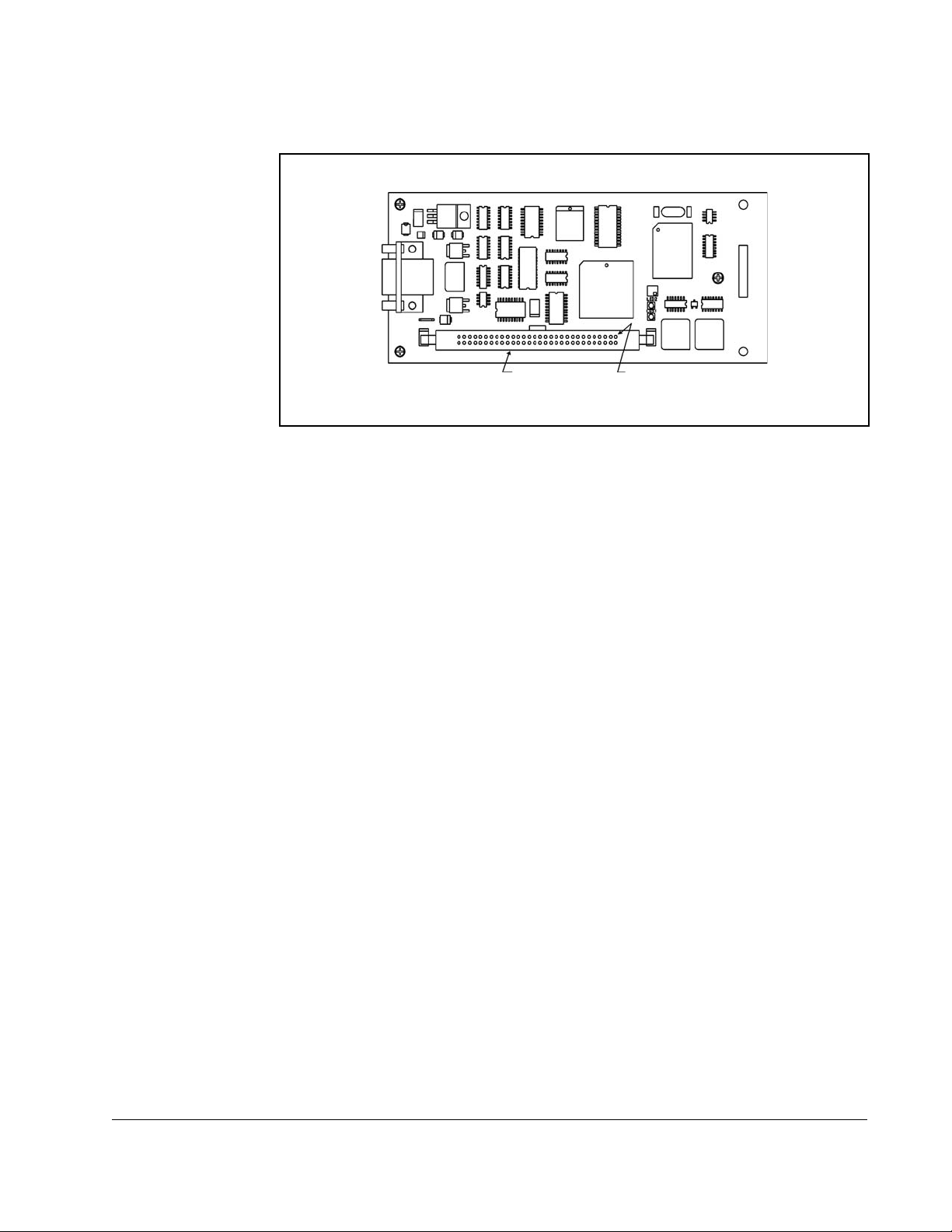
The AutoMax Network Communication Option board is shown in figure 1.1.
9-Pin
D-Shell
Connector
Ribbon Cable
Connector
Pin 1
Figure 1.1 – AutoMax Network Communication Option Board
Introduction
1-3
Page 14

1-4
AutoMax Network Communication Option Board
Page 15
CHAPTER 2
This section describes how to install the Network Option board in the FlexPak 3000 or
WebPak 3000 drive and connect the drive to an AutoMax network.
2.1 Installing the Network Option Board
ATTENTION: Only qualified electrical personnel familiar with the
construction and operation of this equipment and the hazards involved
!
should install, adjust, operate, or service this equipment. Read and
understand this manual and other applicable manuals in their entirety
before proceeding. Failure to observe this precaution could result in
severe bodily injury or loss of life.
ATTENTION:
local, national, and international codes. Wiring practices, grounding,
disconnects, and overcurrent protection are particularly impor tant. Failure
to observe this precaution could result in severe bodily injury or loss of life.
ATTENTION: Do not install modification boards with power applied to
the drive. Disconnect and lock out incoming power before attempting
such installation. Failure to observe this precaution could result in severe
bodily injury or loss of life.
The user is responsible for conforming with all applicable
Installation
To install the Network Option board:
Step 1. Turn off, lock out, and tag all incoming power to the drive.
Step 2. Loosen the two (2) captive screws on the drive cover. Remove the cover.
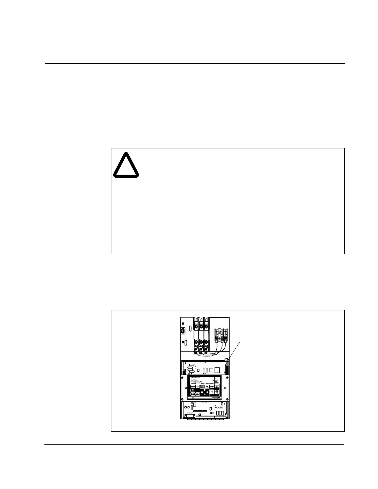
Step 3. Loosen the captive screw on the carrier. Swing open the carrier. See figure 2.1.
Loosen Captive Screw
and Swing Carrier Open
Figure 2.1 – Removing Drive Cover
Installation
2-1
Page 16
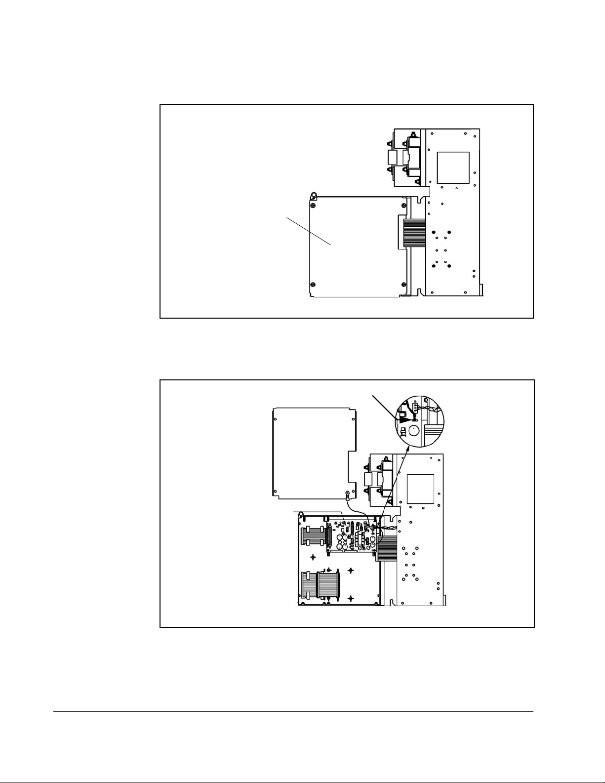
Step 4. Remove the screws that attach the carrier shield to the carrier. See
figure 2.2.
Carrier Shield
Figure 2.2 – Removing the Carrier Shield
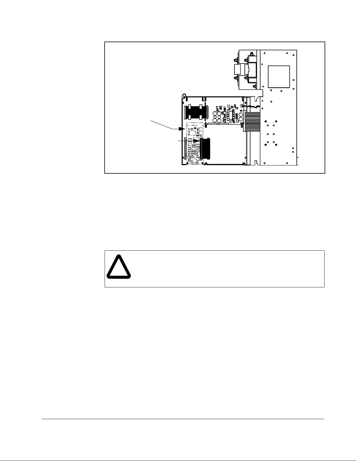
Step 5. Remove the connector that attaches the shield ground wire to the drive
power supply. Set the shield aside. See figure 2.3.
Ground Wire
Power Supply
Figure 2.3 – Removing Shield Ground Wire
Step 6. Position the Network Option board over the standoffs. Refer to figure 2.4.
2-2
Step 7. Secure the Network Option board using three captive screws on the board.
Step 8. Plug the option board ribbon cable into the Network Option board.
AutoMax Network Communication Option Board
Page 17
Attach Network board to
carrier’s molded standoffs
using captive screws
(qty. 3)
Plug option board ribbon
cable into Network board
Figure 2.4 – Installing the Network Communication Option Board
Step 9. Re-attach the carrier shield ground wire to the drive power supply.
Step 10. Re-attach the carrier shield to the carrier.
Step 11. Close the carrier and fasten it with the captive screw.
Step 12. Re-install the drive cover.
2.2 Connecting the Drive to an AutoMax Network
ATTENTION: AutoMax networks with more than 5 drops might produce
communication errors if 10-foot drop cables are used. Wherever possible,
!
3-foot drop cables or, if necessary, 5-foot drop cables should be used.
Failure to observe this precaution could result in damage to, or
destruction of, equipment.
Installation
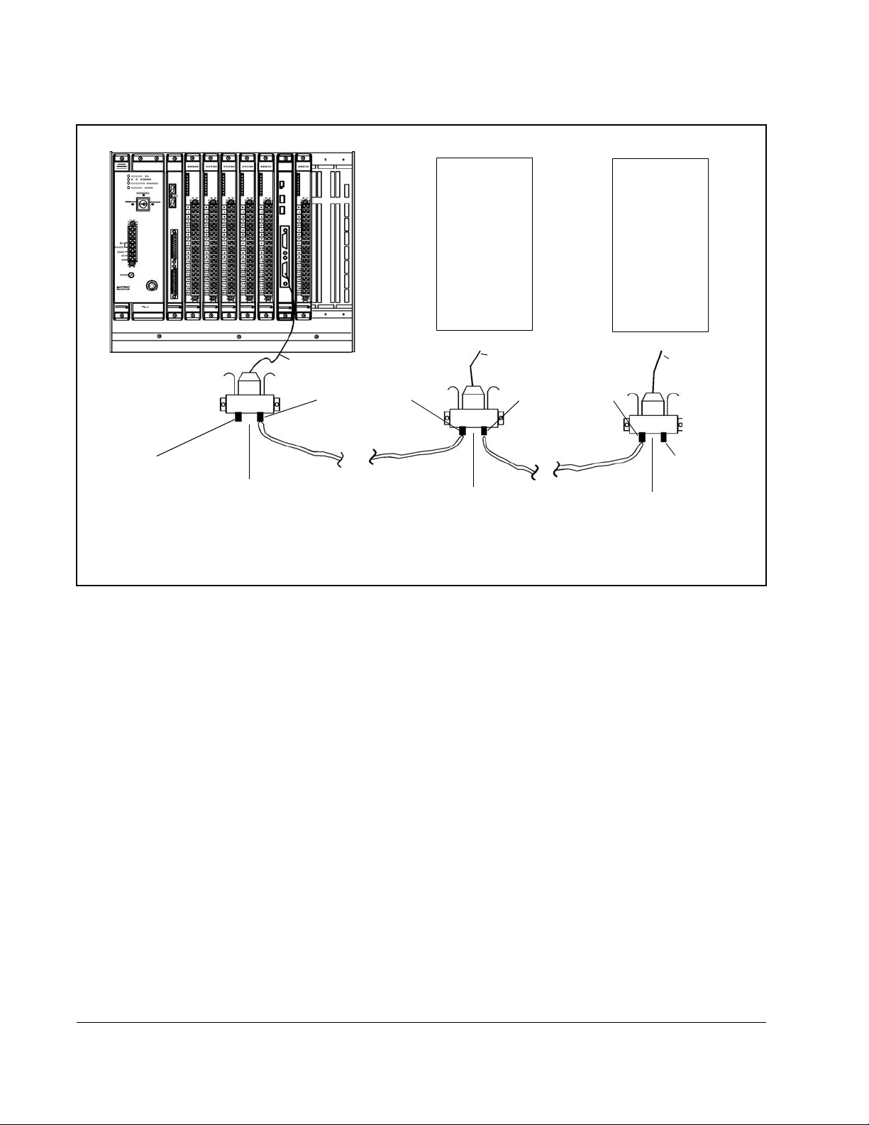
See figure 2.5 for cabling and termination connections.
Refer to the Network Communications Module instruction manual (J2-3001) for a
detailed description of how to add a drop to the network.
Step 1. Stop any application tasks that are running.
Step 2. Use the Network Drop Cable (M/N 57C381) to connect to the
Communications Passive Tap (M/N57C380).
Step 3. If the drop is at the end of the coaxial cable system, it must be terminated.
Terminate by connecting a 75-Ohm Terminating Load (M/N 45C71) to the
remaining BNC connector on the passive tap.
Step 4. Remove the lockout and tag. Apply power to the drive. If a problem is
detected during diagnostics, a fault or alarm will occur. See your drive
software manual for information on faults and alarms.
2-3
Page 18
Drop Cable
(M/N 57C381)
BNC Connector
FlexPak 3000
FlexPak 3000
or
WebPak 3000
Drive
WebPak 3000
Drive
To Drive To Drive
Drop Cable
(M/N 57C381)
BNC Connector
or
Drop Cable
(M/N 57C381)
75 Ohm
Terminating Load
Passive Tap
(M/N 57C380)
Figure 2.5 – Connecting a Drive to the AutoMax Network
Coaxial
Cable
Passive Tap
(M/N 57C380)
Coaxial
Cable
75 Ohm
Terminating Load
Passive Tap
(M/N 57C380)
2-4
AutoMax Network Communication Option Board
Page 19

CHAPTER 3
Drive Configuration
This section describes how to configure a FlexPak 3000 or WebPak 3000 drive for use
with an AutoMax network.
3.1 Setting Up the Drive for Network Communication
The drive becomes active on the AutoMax network after you complete the following
steps:
Step 1. Connect the Network Option board to the network using a passive tap. See
section 2.2.
Step 2. Apply power to the drive.
Step 3. Assign a valid AutoMax network drop number to the drive using parameter
NETW DROP NUMBER (P.900). You must set this parameter through the drive
keypad (
WebPakCS). This drop number is the base drop the drive will occupy. In this
manual, the base drop number is called Drop_1.
When
the network.
FlexPak 3000 drives
sequential network drops, including Drop_1. Subsequent drops are called
Drop_2, Drop_3, and Drop_4 in this manual. Your application might use
different drop numbers.
WebPak 3000 drives:
sequential network drops, including Drop_1. Subsequent drops are called
Drop_2 and Drop_3 in this manual. Your application might use different drop
numbers.
Step 4. Set the network connection type using NETW CONNECT TYPE (P.910). This
defines the scope of data that will be communicated. It also determines the
level of control that the master has with the connected drive. You can select
one of two connection types:
• BASIC: Only essential drive data (reference, sequencing, basic tuning, and
• FULL: The entire set of drive data that has been assigned network
OIM or DCM) or using drive configuration software (CS3000 or
NETW DROP NUMBER
feedback data) are transferred over the network. This allows a higher
density network with moderate functionality. Select this connection type if
you do not need to completely configure the drive over the network. When
BASIC is selected, the drive occupies a single network drop.
registers is transferred over the network. Select this connection type if
your application must be able to configure the drive over the network and
have access to most parameters, operating variables, and diagnostic
information.
The large amount of data transferred in the full connection type requires
that the drive occupy multiple network drops, thus decreasing the
potential number of devices on the network.
(P.900) is set, you can set other parameters over
: For
FULL
connections, the drive occupies four
For
FULL
connections, the drive occupies three
Drive Configuration
3-1
Page 20

FlexPak 3000 drives:
sequential network drops.
WebPak 3000 drives:
sequential network drops using indirect registers in Drop_2 and Drop_3 (see
section 7.1 for information about using indirect registers).
Step 5. Apply power to the AutoMax rack.
Serial communication is now established and information can be exchanged with the
network master. The drive transfers output data whenever this connection is made. To
transfer input data, you must complete the steps in the next section.
When
When
FULL
is selected, the drive will occupy four
FULL
is selected, the drive will occupy three
3.2 Selecting a Network Reference Source
AMX NETW REF SELECT (P.911) specifies the source of the speed/torque reference
when
CONTROL SOURCE SELECT (P.000) is set to NETWORK. You can select either:
• DIRECT: The reference is from register 33 in the drive’s Drop_1 register map. See
table 5.4 (FlexPak 3000 original map), table 6.4 (FlexPak 3000 alternate map), or
table 7.5 (WebPak 3000 map).
• BROADCAST n: The reference is from one of the eight network broadcast data
registers (network drop area 0, registers 32 to 39). The specific broadcast register
(1 to 8) is assigned using a register in the drive’s Drop_1 register map. See
register 30 in table 5.3 (FlexPak 3000 original map), register 63 in table 6.6 (FlexPak
3000 alternate map), or register 30 in table 7.4 (WebPak 3000 map). See the
Network Communications Module instruction manual (J2-3001) for information on
broadcast data registers.
3.3 How the Drive Responds to a Loss of Network
Communication
The Network Option board attempts to remain active on the network at all times,
regardless of the control source setting.
At power up, the drive delays for approximately 10 seconds before indicating a loss of
network communication.
If communication is interrupted:
• The Network Option board immediately notifies the drive Regulator.
• The Network Option board tries to re-establish communication with the network
master.
• For FlexPak 3000 drives, if CONTROL SOURCE SELECT (P.000) is set to NETWORK, the
drive reacts to a network communication loss as specified by
SELECT (P.901).
• For WebPak 3000 drives, a fault is generated when network communication is lost if
CONTROL SOURCE SELECT (P.000) is set to NETWORK.
• If the drive includes an OIM, the NETWORK indicator above the CONTROL SOURCE
SELECT key blinks to indicate that network communication is inactive.
NETW COMM LOSS
3-2
AutoMax Network Communication Option Board
Page 21
3.3.1 Setting NETW COMM LOSS SELECT (P.901)
(FlexPak 3000 Drives Only)
ATTENTION: NETW COMM LOSS SELECT (P.901) allows you to configure
the drive to continue to run of a loss of network communication occurs.
!
NETW COMM LOSS SELECT (P.901) is not used in WebPak 3000 drives. For
WebPak 3000 drives, a fault is generated when network communication is lost if
CONTROL SOURCE SELECT (P.000) is set to NETWORK. This causes the drive to coast/DB
stop. The drive cannot be restarted until the fault is cleared.
You must provide some form of hardwired stop in case of communication
loss, since stopping the drive over the network might not be possible.
Failure to observe this precaution could result in bodily injury or damage
to, or destruction of, equipment.
For FlexPak 3000 drives,
responds to network communication loss when
to network. Alarms do not cause the drive to stop. Therefore, some form of hardwired
stop must be available in case of communication loss since stopping the drive over the
network might not be possible.
You can set
TRMBLK REF (2), or USE TRMBLK CNTL (3).
P.901 = FAULT (0)
When
lost, the following occurs:
NETW COMM LOSS SELECT (P.901) to FAULT (0), USE LAST REF (1), USE
NETW COMM LOSS SELECT (P.901) is set to FAU LT and network communication is
NETW COMM LOSS SELECT (P.901) defines how the drive
CONTROL SOURCE SELECT (P.000) is set
• The drive latches a fault condition and performs a coast/DB stop.
• A NETWORK COMMUNICATION LOSS fault is generated.
When network communication is re-established, you must reset the fault before the
drive can be re-started. See the drive software manual for information on resetting
faults.
ATTENTION: The drive is not equipped with a coast-stop pushbutton.
You must install a hardwired operator-accesible pushbutton that provides
!
a positive interrupt and shuts down the drive. Failure to observe this
precaution could result in bodily injury.
ATTENTION:
MAP SEL
NETWORK
SPD LOOP PI RESET
these values are appropriate for your application before changing the
control source. Failure to observe this precaution could result in severe
bodily injury or loss of life.
If you are using the alternate register map (
(P.914) set to
, the parameters
ALTERNATE
are reset to their default values (0 for each). Ensure
) and you change the control source from
SPD LOOP PI INIT SEL, SPD LOOP PI INIT VAL
NETW REGISTER
, and
Drive Configuration
3-3
Page 22

P.901 = USE LAST REF (1)
NETW COMM LOSS SELECT (P.901) is set to USE LAST REF and network
When
communication is lost, the following occurs:
• The drive continues to run, using the last reference received from the network
master.
• A NETWORK COMMUNICATION TIMEOUT alarm (A00004) is generated.
• An entry is made into the drive’s alarm log for each active-to-inactive transition of
network communication status.
• If network communication is re-established and the drive is still running, the drive
will again follow the reference and sequencing control inputs supplied by the
network master.
You can stop the drive using the hardwired stop input or the
However, you cannot restart the drive until network communication is re-established or
CONTROL SOURCE SELECT (P.000) is changed.
P.901 = USE TRMBLK REF (2)
NETW COMM LOSS SELECT (P.901) is set to USE TERMBLK REF (2) and network
When
communication is lost, the following occurs:
OIM STOP/RESET key.
• The drive continues to run, using the auto reference value selected by AUTO
REFERENCE SELECT (P.103)
(or Regulator board terminals 19 and 20?)
• A NETWORK COMMUNICATION TIMEOUT alarm (A000014) is generated.
• If network communication is re-established and the drive is still running, the drive
will again follow the reference and sequencing control inputs supplied by the
network master.
You can stop the drive using the hardwired stop input, the
hardwired stop input (coast/DB stop, Regulator board terminal 8). However, you
cannot restart the drive until network communication is re-established or
SOURCE SELECT (P.000) is changed.
P.901 = USE TRMBLK CNTL (3)
NETW COMM LOSS SELECT (P.901) is set to USE TRMBLK CNTL (3), and network
When
communication is lost, the following occurs:
OIM STOP/RESET key, or the
CONTROL
3-4
• The drive continues to run using the Regulator board terminal strip as the source for
all control (run, jog, stop, fault reset, direction, and OCL enable) and speed (auto)
reference signals.
• A NETWORK COMMUNICATION TIMEOUT alarm (A000014) is generated.
• The Speed Loop PI Reset and Underwind/Overwind bits cannot be changed while
operating in this mode. They will remain at the last values received from the
network.
If network communication is re-established and the drive is still running, the drive will
again frollow the reference and sequencing control inputs supplied by the network
master.
AutoMax Network Communication Option Board
Page 23

CHAPTER 4
Programming
This section describes the organization of data in the AutoMax Network
Communication Option board and how the network accesses the data.
4.1 Selecting a Register Map (FlexPak 3000 Drives Only)
There are two register maps available for the FlexPak 3000 drive: original and
alternate.
The original register map allows you to use programs developed for versions earlier
than 4.0 of the FlexPak 3000 drive. Register assignments for the original register map
are listed in chapter 5.
The alternate register map is similar to the original register map, except that the most
commonly accessed data is in the base drop area (Drop_1). The alternate register
map also includes functions that were added in regulator software version
FlexPak 3000 DC Drive Software Reference Manual
the
details on the new version
map are listed in chapter 6.
4.2
features. Register assignments for the alternate register
, manual number D2-3405, for
4.2
. See
Important: When a version
existing AutoMax network that uses the ALTERNATE register map, you
may need to reprogram the master task so that it writes valid data in the
registers that are now being used (where previously they were marked as
reserved).
The register map is selected using the
4.2
Regulator board is used as a replacement in an
NETW REGISTER MAP SEL (P.914) parameter.
4.2 How the Control Source Selection Affects Data
Transfers
You can use the keypad to change parameter values when CONTROL SOURCE SELECT
(P.000) is set to
overwritten when the next network update occurs.
You cannot transfer data using the CS3000
SOURCE SELECT (P.000) is set to NETWORK.
NETWORK. However, changes made through the keypad might be
OR WebPakCS software while CONTROL
4.3 About Network Transfer Rates
To transfer data, the Network Option board must be communicating with the master.
To transfer input data, the Network Option board must be communicating with the
master and
CONTROL SOURCE SELECT (P.000) must be set to NETWORK.
Programming
Data transfer rates between the Network Option board and Regulator board depend
on the type of data being transferred.
4-1
Page 24

Data can be input or output data.
Input data is one of three types:
• Control/Reference: Data that require the fastest update rates, including data such
as the sequencing inputs (Stop, Run, Jog, Fwd/Rev) and speed/torque reference.
These inputs are transferred every speed loop scan period. An exception to this
occurs if the drive is configured to get its torque reference from the network. If the
torque reference is from the network, the drive reads the
CML reference from the
Network Option board every current minor loop scan.
•
Tunable:
TIME
Data that can be changed while the drive is running, such as
ACCELERATION
(P.001). Tunable inputs are transferred approximately every 600 msec while the
drive is running or stopped.
• Configurable: Data that cannot be changed while the drive is running, such as
CONTROL SOURCE SELECT (P.000). Configurable inputs are transferred from the
Network Option board to the Regulator board approximately every 600 msec when
the drive is stopped. Values sent from the network master while the drive is running
are stored in Network Option board memory but are not scanned into Regulator
board memory until the drive is stopped.
Output data is one of two types:
• Runtime Signal: Data such as the selected speed reference value, drive status
(such as ready or running), drive fault flags, the state of terminal strip digital inputs,
and motor status values (
speed loop scan period.
RPM, VOLTS, AMPS). This information is transferred every
• Tunable, Configurable, and Status: All other information provided by the drive.
This typically includes all stored drive parameter values. Tunable, configurable, and
status data are transferred approximately every 600 msec.
Output data is transferred from the Regulator board to the Network Option board
regardless of the status of AutoMax network communication (active or inactive) or the
selected drive control source (
For FlexPak 3000 drives, the speed loop scan period is 10 msec when
SELECT (P.200) is set to ARMATURE VOLT. It is 5 msec when FEEDBACK SELECT (P.200) is
set to any other value.
For WebPak 3000 drives, the speed loop scan period is 10 msec.
KEYPAD, TERMBLK, or NETWORK).
FEEDBACK
4-2
AutoMax Network Communication Option Board
Page 25
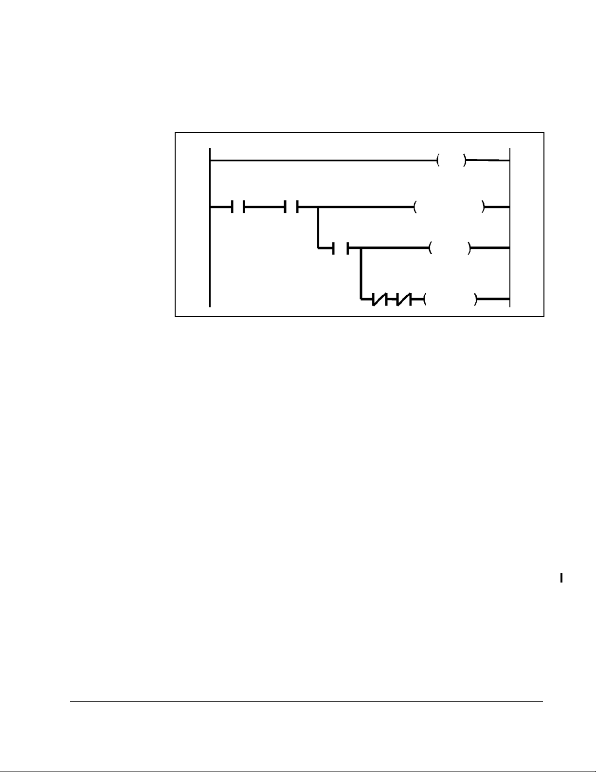
4.3.1 I/O Update Enable Logic Summary
The logic strings shown in figure 4.1 summarize the output and input enable logic
described in this chapter.
Outputs
Updated
CONTROL SOURCE
NETW COMM STATUS
(P.908) = ACTIVE
SELECT = NETWORK
Tune/Config
Input Enable
Running
Jogging
Figure 4.1 – I/O Update Enable Logic Strings
Control/Reference
Inputs Read
Tu na b le
Inputs Read
Configurable
Inputs Read
4.4 Setting Up Data Types That Can Be Transferred
You must enable the transfer of tunable and configurable inputs from the Network
Option board to the Regulator board. Until you enable transfer, only control/reference
data are read by the Regulator board.
To enable transfer of tunable and configurable data, set the network-master-controlled
Tune/Config Input Enable bit (Drop_1, register 32, bit 14) to 1.
For example, the master application program would typically:
1. Initialize the tunable and configurable input data in the dual-port memory of the
master’s Network module
2. Delay for an appropriate amount of time to ensure data have been transferred to
the drive
3. Set the Tune/Config Input Enable bit to 1.
If you only want to transfer control/reference data, leave the Tune/Config Input Enable
bit at 0 (off). This forces you to configure the drive through another source, such as the
OIM, CS3000 software, or WebPakCS software, but allows you to control the drive
(including
RUN, JOG, STOP, RESET, and the reference) from the network master.
Programming
4-3
Page 26

4.5 Tune/Config Update Synchronization Flag
This flag allows the network master application program to track when the drive has
updated tunable and configurable inputs. By toggling the tune/config update
synchronization flag in the master and monitoring the copied value from the drive, the
master’s program can determine when the drive has read in that data. This feature has
no effect on drive operation.
The drive regulator copies the tune/config update synchronization flag bit to its
corresponding loopback bit after it has read in and processed all tunable input
registers. Configurable inputs are only read in by the drive while it is not running. This
will not affect copying the synchronization flag to the loopback bit, since tunable inputs
will still be transferred.
When using WebPak 3000 indirect parameters, use the tune/config update
synchronization flag with the network synchronization flag as described in section 7.1.
To use the synchronization flag, the tune/config input enable bit must be set to 1.
To determine when changes to tunable and configurable data in the drive have been
completed, the master:
1. Modifies the tunable and configurable register data in the appropriate network
registers.
2. Sets the tune/config input enable flag.
3. Toggles the tune/config update synchronization flag.
4. Monitors the tune/config update synchronization flag loopback bit until it equals
the value written in item 3, above.
The tune/config update synchronization flag is defined in the first drop of the drive
network drop connection. Therefore, it can only be used to indicate when data for the
first drop has been read in and processed by the drive.
Table 4.1 – Synchronization Flag Register Locations (Alternate and Original Register Maps)
Flag Drop Register Bit
Tune/Config Update Synchronization Flag Loopback
(Master Read) Bit
Tune/Config Update Synchronization Flag (Master
Write)
Tune/Config Input Enable Bit Drop_1 32 14
Alternative Synchronization Methods
The tune/config update synchronization flag applies only to Drop_1. To determine if
the drive received data written to other drops, you must use other methods.
One method is to program a delay after writing to the network master’s memory.
Calculate the delay as needed for the number of drops on the network, adding
600 msec for processing time. See your AutoMax documentation for information on
calculating the delay.
Drop_1 0 7
Drop_1 32 15
4-4
AutoMax Network Communication Option Board
Page 27

Note that this method assumes that all requirements have been met for the drive to
obtain its inputs from the network (see figure 4.1).
4.6 Monitoring Unacceptable Parameter Values
The parameter processing error status flag (FlexPak drives: Drop_1, register 0, bit 12;
WebPak drives: Drop_1, register 0, bit 13) allows the network master to monitor
parameter values that are unacceptable to the drive.
When this flag is set to 1, one or more parameters sent to the drive were rejected.
When this flag is set to 0, all parameters sent to the drive were accepted.
Note that the Tune/Config Inputs Enable bit (Drop_1, register 32, bit 14) must be set
to 1 before the drive will read or process any tune/config parameters. The parameter
processing error flag is updated approximately every 600 msec.
More information on parameter processing errors is available when using the
FlexPak 3000 alternate register map (see section 6.2) or the WebPak 3000 register
map (see section 7.1).
4.7 Timing Requirements
The amount of time required by the network master to transmit data to the drive
depends on the number of active drops on the network. This time is referred to as the
“data update time.” Refer to I/M J2-3001 for details on calculating this time.
Tunable and configurable drive input register values must be maintained by the
network master’s application program for the data update time plus at least 600 msec
to assure that they are read by the drive.
Most of the control/reference data types do not have this 600 msec requirement
because they are read by the drive every 5 or 10 msec.
To start the drive, the Run and Jog inputs must be set to 0 for at least 20 msec, then
set to 1 for at least 20 msec (a 0-to-1 transition). The drive might delay the start for up
to 100 msec after receiving the 0-to-1 transition because of variable processing
delays.
For the following actions, the inputs must be set to 0 for at least 600 msec, then set to
1 for at least 600 msec (a 0-to-1 transition):
• Fault log clear
• Alarm log clear
• Alarm reset
• Memory save
Programming
To reset faults, the inputs must be set to 0 for at least 10 msec, then set to 1 for at
least 10 msec (a 0-to-1 transition).
4-5
Page 28

4.8 Drive Ready Status Bit
The Drive Ready status bit (Drop_1, register 0, bit 0) indicates that a 0-to-1 transition
on the Run or Jog input will start the drive.
FlexPak 3000 drives: The Drive Ready bit is
conditions are met, and
OFF (0) if any one of these conditions is not met:
ON (1) when all of the following
• No drive faults are active (Drop_1, register 0, bit 2 = 0)
• Network stop input is de-asserted (Drop_1, register 32, bit 1 = 1)
• Front-panel STOP/RESET button is not pressed
• Coast/DB Stop terminal strip input is closed (Drop_1, register 0, bit 10 = 1)
• Customer Interlock terminal strip input is closed (Drop_1, register 0, bit 11 = 1)
• A download from the serial port (using the CS3000 software) is not in progress
WebPak 3000 drives: The Drive Ready bit is on (1) when all of the following
conditions are met, and off (0) if any one of these conditions is not met:
•
•
4.9 Display of Parameter Values Over the
AutoMax Network
The display of parameter values on the network will be different than the display when
on the
OIM, DCM, or when using CS3000 or WebPakCS software.
Examples of these differences are shown in table 4.2. Refer to the register maps in
chapters 5 and 6 for detail on the scaling parameter for transfer over the AutoMax
network.
Front Panel Display (OIM or DCM)
Values with a decimal
point
Parameters with text
choices
Speed/voltage loop
and current minor loop
parameters
*
For speed parameters, a value of 4095 corresponds to TOP SPEED (P.011). For load parameters, 4095 corresponds to MAXIMUM CURRENT
(P.007).
4-6
(Does this table need to be revised for WebPak?)
Table 4.2 – Front Panel Display Compared to Network Displays
Network Value
Set
MOTOR RATED ARM AMPS (P.008) to
27.3 amps.
TRIM MODE SELECT (P.110) choices are
NO TRIM, INCREMENTAL, or
PROPORTIONAL.
TOP SPEED (P.011) = 1750 RPM. On the
front panel, you read
FEEDBACK (P.296) = 1000 RPM.
SPD LOOP
2340
AutoMax Network Communication Option Board
Register Map Table
Listing ExampleDescription Example
273 amps * 10
0, 1, 2 0 =
NO TRIM
1 = INCREMENTAL
2 = PROPORTIONAL
4095 1000×
⎛⎞
-------------------- ------------ -
=
⎝⎠
1750
4095 at
(P.011)
TOP SPEED
*
Page 29

4.10 Parameters That Are Not Accessible Over the
AutoMax Network
These FlexPak 3000 parameters are not accessible over the AutoMax network at
any time.
ANALOG MAN REFERENCE (P.192)
ANLG OUT 1 SIG TYPE (P.419)
*
ARMATURE DELTA (P.399)
*
CML ERROR (P.398)
*
CML FEEDBACK (P.397)
*
CT TURNS RATIO (P.010)
*
CURRENT COMPOUND TP (P.293)
DEVNET POLL MSG TYPE (P.913)
DIG IN 0 (P.490)
*
DRAW PERCENTAGE OUT (P.196)
*
FIELD DELTA (P.588)
*
FIELD DELTA HIGH LIM (P.587)
*
FLD CURRENT REGULATOR (P.586)
*
I/O EXPANSION KIT (P.797)
*
INV FAULT AVOID SEL (P.312)
*
IR COMPENSATION TP (P.290)
*J11
ANLG TACH VLT SCL (P.792)
*J14
ANLG TACH VLT RNG (P.793)
*J15
REGULATOR TYPE (P.799)
*J18
ARM I FB RESISTOR (P.395)
J20
FIELD LOSS DETECT (P.597)
J21
FLD SUPPLY JUMPER (P.598)
*
JOG OFF DELAY TIME (P.121)
*
JOG RAMP OUTPUT (P.294)
JOG SPEED 2 (P.017)
*
LEVEL DETECT 1 OUTPUT (P.648)
*
LEVEL DETECT 2 OUTPUT (P.649)
MANUAL REF SELECT (P.106)
METER OUT 1 GAIN ADJ (P.400)
METER OUT 1 SELECT (P.404)
METER OUT 1 ZERO ADJ (P.402)
METER OUT 2 GAIN ADJ (P.401)
METER OUT 2 SELECT (P.405)
METER OUT 2 ZERO ADJ (P.403)
MOP ACCEL TIME (P.115)
MOP DECEL TIME (P.120)
MOP OUTPUT (P.191)
MOP RESET ENABLE (P.116)
*
NETW COMM STATUS (P.908)
*
NETW DROP NUMBER (P.900)
*
NETW IN REG 1 (P.905)
*
NETW IN REG 2 (P.906)
*
NETW IN REG 3 (P.907)
*
NETW TYPE & VERSION (P.909)
NETWORK BAUD RATE (P.912)
*
NETWORK KIT (P.796)
OCL ENABLE (P.849)
OCL FEED BACK (P.847)
OCL REFERENCE (P.845)
*
PHASE FIRE TEST DELTA (P.309)
*
PHASE FIRE TST BRIDGE (P.310)
*
POWER UNIT TYPE (P.795)
PRESET SPEED 1 (P.117)
PRESET SPEED 2 (P.118)
PRESET SPEED 3 (P.119)
PULSE TACHOMETER KIT (P.798)
*
SELF TUNE BRIDGE (P.220)
SELF TUNE FIELD RANGE (P.218)
*
SELF TUNE STABILITY (P.219)
*
SPD LOOP LAG OUTPUT (P.298)
*
SPEED RAMP INPUT TP (P.198)
*
SPEED RAMP OUTPUT (P.199)
*
TACH LEAD FLT DELAY (P.228)
*
TACH LEAD FLT THRESH (P.227)
*
TORQUE REFERENCE (P.189)
*
CNI PROG/RUN MODE (P.915)
Programming
* Indicates WebPak parameters. Are there other WebPak parameters? Should
we make separate sections for WebPak and FlexPak?
4-7
Page 30

4.11 Parameters That Are Only Available in the FlexPak
Alternate Register Map
RAMP STOP DECEL TIME (P.018)
STOP DECEL SELECT (P.122)
NEG CUR LIM INV EN (P.226)
CML REF LIMIT SELECT (P.311)
INV FAULT AVOID SEL (P.312)
DIG IN 0 SELECT (P.428)
TACH LOSS SCR ANGLE (P.608)
PHASE LOSS DETECT (P.609)
OCL PROP TRIM SELECT (P.813)
OCL TYPE3 POSN REG EN (P.814)
NETW REGISTER MAP SEL (P.914)
SPD LOOP PI INIT SEL
LOOP PI INIT VAL
SPD
LOOP PI RESET
SPD
UNDERWIND
ENABLE
Process Error Parameter Number
4.12 Settings for Analog and Frequency Outputs
These are the options you can set for the I/O Expansion kit analog and frequency
output parameters.
CML FEEDBA CK (P.397)
0=
1=
CML REFERENCE (P.396)
2=
CML ERROR (P.398)
3=
SPD LOOP FEEDBACK (P.296)
4=
SPD LOOP REFERENCE (P.295)
5=
SPD LOOP ERROR (P.297)
6=
SPD LOOP OUTPUT (P.299)
7=
SPEED RAMP OUTPUT (P.199)
8=
SPEED RAMP INPUT TP (P.198)
9=
SPD SOURCE SELECT OUT (P.193)
10=
TRIM OUTPUT (P.197)
11=
ARMATURE VOLTAGE (P.289)
12=
ANALOG TACH FEEDBACK (P.291)
PULSE TACH FEEDBACK (P.292)
13=
14=
ZERO
15=FULL SCALE
16=POWER OUTPUT
17=OCL REFERENCE (P.845)
18=
OCL RAMP OUTPUT (P.846)
19=
OCL FEEDBACK (P.847)
20=
OCL OUTPUT (P.848)
21=
FIELD REFERENCE (P.590)
22=
FIELD FEEDBACK (P.589)
23=
NETW IN REG 1 (P.905)
24=
NETW IN REG 2 (P.906)
25=
NETW IN REG 3 (P.907)
4-8
Same for WebPak?
AutoMax Network Communication Option Board
Page 31

CHAPTER 5
FlexPak 3000 Drives:
Original Register Map
This section lists the original register map, which allows you to use programs
developed for versions earlier than 4.0 of the FlexPak 3000 drive. It also offers a
different set of options in Drop_1 than the alternate register map.
Brief descriptions of parameters are in the register map tables. For detailed parameter
descriptions, refer to the
5.1 Accessing the Original Register Map
To access the original register map, set NETW REGISTER MAP SEL (P.914) to ORIGINAL.
FlexPak 3000 DC Drive Software Reference Manual
.
Some parameters are not available and others are mapped differently when
REGISTER MAP SEL
correct mappings if you switch from the alternate register map to the original register map.
(P.914) is set to
ALTERNATE
. Make sure your application uses the
NETW
5.2 Finding Data in the Original Register Map Tables
The original register map shown in tables 5.2 through 5.18 describes the registers and
bits used by the FlexPak 3000 drive on the AutoMax network when
MAP SEL (P.914) is set to ORIGINAL.
There are no write registers for control/reference data for Drop_2, Drop_3, and Drop_4.
Table 5.1 – Location of Information in the Original Register Map Tables
Drop_# Master… Data Type Table Page
1 Read Runtime Signal 5.2 5-2
Tunable, Configurable, and Status 5.3 5-4
Write Control/Reference 5.4 5-6
Tunable 5.5 5-7
Configurable 5.6 5-8
2 Read Runtime Signal 5.7 5-8
Tunable, Configurable, and Status 5.8 5-8
Write Tunable 5.9 5-9
Configurable 5.10 5-10
3 Read Runtime Signal 5.11 5-11
Tunable, Configurable, and Status 5.12 5-12
Write Tunable 5.13 5-12
Configurable 5.14 5-13
4 Read Runtime Signal 5.15 5-14
Tunable, Configurable, and Status 5.16 5-15
Write Tunable 5.17 5-16
Configurable 5.18 5-17
NETW REGISTER
FlexPak 3000 Drives: Original Register Map
5-1
Page 32

5-2
AutoMax Network Communication Option Board
Table 5.2 – FlexPak 3000 Original Register Map, Drop_1: Master Read Registers, BASIC and FULL Connections. Runtime Signal Data (Drive Output Data)
Register Bit Parameter Name (Number) Description Settings
0 Drive status word 1 Bit-packed word containing information on the present status of the drive
0 Drive ready
1Drive running
2 Fault active
3 Drive jogging
4 Forward/reverse command 0=forward; 1=reverse
5 Drive stopping
6 Tune/config input enable loopback 0=disabled; 1=enabled
7 Tune/config update synch. flag loopback (master read)
8 Alarm active
9 In current limit
10 Coast/DB interlock 0=open; 1=closed
11 Customer interlock 0=open; 1=closed
12 Parameter processing error 0=no errors; 1=one or more errors
13 Terminal strip forward/reverse input state (terminal 5)
14 Terminal strip auto/manual input state (terminal 6)
15 Terminal strip fault/alarm reset input state (terminal 10)
1
2
3
4
5
6Average
7 Network Output Register 1 Value of the parameter selected by
8 Network Output Register 2 Value of the parameter selected by NETW OUT REG 2
9 Network Output Register 3 Value of the parameter selected by
10 to 15 Tunable, Configurable and Status Data See table 5.3 on page 5-4.
Runtime signal data are updated by the regulator every 5 msec, unless
SPD SOURCE SELECT OUT (P.193) Selected speed/voltage loop reference value 4095 at TOP SPEED (P.011)
SPD LOOP REFERENCE (P.295) Final speed/voltage loop reference value 4095 at TOP SPEED (P.011)
SPD LOOP FEEDBACK (P.296) Final speed/voltage loop feedback value after all scaling 4095 at TOP SPEED (P.011)
SPD LOOP OUTPUT (P.299) Speed loop PI block output value 4095 at MAXIMUM CURRENT (P.007
ARMATURE VOLTAGE (P.289) Armature voltage feedback value 4095 at MOTOR RATED ARM VOLTS (P.009)
CML feedback CML feedback average over eight CML scans 4095 at MAXIMUM CURRENT (P.007)
NETW OUT REG 1
SELECT (P.902)
If no valid parameter value selected,
0=motor speed in RPM
If no valid parameter value selected,
SELECT (P.903)
NETW OUT REG 3
SELECT (P.904)
FEEDBACK SELECT (P.200) is set to ARMATURE VOLT, in which case the update time is 10 msec.
0=armature voltage in volts
If no valid parameter value selected,
0=armature current in amps*10 or amps
Page 33

FlexPak 3000 Drives: Original Register Map
Table 5.2 – FlexPak 3000 Original Register Map, Drop_1: Master Read Registers, BASIC and FULL Connections. Runtime Signal Data (Drive Output Data) (Continued)
Register Bit Parameter Name (Number) Description Settings
16 ANALOG AUTO REFERENCE (P.188) The analog reference value in auto mode after all scaling 4095 at TOP SPEED (P.011)
17
18
19
20
21
22
23
Runtime signal data are updated by the regulator every 5 msec, unless FEEDBACK SELECT (P.200) is set to ARMATURE VOLT, in which case the update time is 10 msec.
ANALOG MAN TRIM REF (P.194) Analog manual trim reference input value 4095 at TOP SPEED (P.011)
ANLG IN 1 (P.492) I/O Exp. kit analog input 1 after gain and zero applied 4095 at full scale
ANLG IN 2 (P.493) I/O Exp. kit analog input 2 after gain and zero applied 4095 at full scale
FREQ IN (P.491) I/O Expansion kit frequency input value after all scaling 4095 at full scale
OCL OUTPUT (P.848) Outer control loop output value RPM
FIELD FEEDBACK (P.589) Motor field current feedback value after scaling and gain 4095 at MOTOR HOT FLD AMPS (P.510)
AC LINE VOLTAGE (P.392) Measured AC line RMS voltage volts RMS
5-3
Page 34

5-4
AutoMax Network Communication Option Board
Table 5.3 – FlexPak 3000 Original Register Map, Drop_1: Master Read Registers, BASIC and FULL Connections. Tunable, Configurable, and Status Data (Drive Output Data)
Register Bit Parameter Name (Number) Description Settings
10 Fault latch bits word 1 Bit-packed word indicating latched faults
0
1
2
3
4
5
6
7 Reserved
8
9
10
11 OPEN ARMATURE (F00007)
12
13
14
15
11 Reserved
12 First fault Fault code of the first fault since the last fault reset
13 Alarm latch bits word Bit-packed word containing latched alarm bits
0
1
2
3 to 15 Reserved
14 Last alarm Alarm code of the most recent alarm
15
CONTROL SOURCE SELECT (P.000) Selected source for drive control signals
16 ACCELERATION TIME (P.001) Min. time to accelerate from zero to TOP SPEED (P.011) seconds * 10
17
DECELERATION TIME (P.002) Min. time to decelerate from TOP SPEED (P.011) to zero seconds * 10
Tunable, configurable, and status data are updated by the regulator approximately every 600 msec.
AC LINE SYNCHRONIZATION FAULT (F00010)
FIELD CURRENT LOSS (F00004)
SUSTAINED OVERLOAD (F00005)
SELF TUNING FAULT (F00060 to F000099)
MOTOR THERMOSTAT TRIP (F00008)
CONTROLLER THERMOSTAT TRIP (F00009)
BLOWER MOTOR STARTER OPEN (F00006)
IET (OVERCURRENT) (F00001)
OVERSPEED (F00003) / ARMATURE OVERVOLTAGE
(F00012)
SCR N
or
MULTIPLE SCRS NOT OPERATING
TACHOMETER LOSS (F00002)
OIM COMMUNICATIONS TIMEOUT (F00011)
NETWORK COMMUNICATION TIMEOUT (F00013)
REVERS ED TACH LEADS (F00014)
MOTOR BRUSH WEAR LOW (A00001)
AC LINE VOLTAGE LOW (A00002)
AC LINE VOLTAGE HIGH (A00003)
(F00030–F00042)
0=
TERMBLK
; 1=
KEYPAD
; 2=
SERIAL
; 3=
NETWORK
Page 35

FlexPak 3000 Drives: Original Register Map
Table 5.3 – FlexPak 3000 Original Register Map, Drop_1: Master Read Registers, BASIC and FULL Connections. Tunable, Configurable, and Status Data (Drive Output Data) (Continued)
Register Bit Parameter Name (Number) Description Settings
18 MINIMUM SPEED (P.003) Lowest operating speed RPM
19
20
21
22
23
24
25
26
27
28 0
29 NETW COMM LOSS SELECT (P.901) How the drive responds to network communication loss 0=FAUL T; 1 = USE LAST REF; 2=USE TRMBLK
30 AMX NETW REF SELECT (P.911) AutoMax network reference selection 0=DIRECT; 1 to 8 = BROADCAST 1 to 8
31
MAXIMUM SPEED (P.004) Highest operating speed RPM
POSITIVE CURRENT LIM (P.005) Highest amount of current for the forward bridge % of MOTOR RATED ARM AMPS (P.008)
NEGATIVE CURRENT LIM (P.006) Highest amount of current for reverse bridge % of MOTOR RATED AR M AMPS (P.008)
TRIM RANGE (P.109) Amount the trim reference will affect the drive reference %
SPD LOOP PI PROP GAIN (P.211) Speed loop PI proportional gain gain * 100
SPD LOOP PI LEAD FREQ (P.212) Speed loop PI block lead break frequency radians/second * 100
CML PI PROP GAIN (P.301) CML PI proportional gain gain * 1000
CML PI LEAD FREQUENCY (P.302) CML PI lead break frequency radians/second
CML REF RATE LIMIT (P.303)
NETW CONNECT TYPE (P.910) AutoMax network connection type 0=BASIC; 1=FULL
Min. time for
CML
ref. to go from zero to
MAXIMUM CURRENT
milliseconds
8 NETW REGISTER MAP SEL (P.914) Network register map selected 0=ORIGINAL; 1=ALTERNATE
REF, 3=USE TRMBLK CNTL
REGULATOR SW VERSION (P.794) Regulator board software version
Tunable, configurable, and status data are updated by the regulator approximately every 600 msec.
5-5
Page 36

5-6
AutoMax Network Communication Option Board
Table 5.4 – FlexPak 3000 Original Register Map, Drop_1: Master Write Registers, BASIC and FULL Connections. Control/Reference Data (Drive Input Data)
Register Bit Parameter Name (Number) Description Settings
32 Sequencing control word Word containing drive sequencing and control bits
0 Run 0 to 1 transition to run
1 Stop 0=stop; 1= not stop
2 Fault reset 0 to 1 transition to reset
3 Jog 0 to 1 transition to jog; 0=stop jogging
4 Forward/reverse select 0=forward; 1=reverse
5 to 6 Reserved
7 Outer control loop enable 0 =hold
8 Fault log clear and reset 0 to 1 transition to clear
9 Alarm log clear and reset 0 to 1 transition to clear
10 Alarm reset 0 to 1 transition to reset
11 Memory save 0 to 1 transition to save
12 – 13 Reserved
14 Tune/config input enable: Determines what is read from
network. “Read all” includes control/reference, tunable,
and configurable inputs
15 Tune/config update synchronization flag (master write)
33 Network Reference Speed/voltage loop or
CONTROL SOURCE SELECT (P.000) is set to NETWORK and
AMX NETW REF SELECT (P.911)= 0
CML reference value when
34 Network Input Register 1 Written by network master. Read this value through the
OIM or DCM using NETW IN REG 1 (P.905)
35 Network Input Register 2 Written by network master. Read this value through the
OIM or DCM using NETW IN REG 2 (P.906)
36 Network Input Register 3 Written by network master. Read this value through the
OIM or DCM using NETW IN REG 3 (P.907)
37
FIELD REF REGISTER (P.513) Reference for the field current loop 4095 at MOTOR HOT FLD AMPS (P.510)
38 to 39 Reserved
Control/reference data are read by the regulator every 5 msec, unless
FEEDBACK SELECT (P.200) is set to ARMATURE VOLT, in which case the update time is 10 msec.
0=read only control/reference inputs
1=read all
4095 at
ARM VOLTS (P.009) or MAXIMUM CURRENT
(P.007)
OCL in reset; 1=OCL enabled
TOP SPEED (P.011)/MOTOR RATED
Page 37

FlexPak 3000 Drives: Original Register Map
Table 5.5 – FlexPak 3000 Original Register Map, Drop_1: Master Write Registers, BASIC and FULL Connections. Tunable Data (Drive Input Data)
Register Bit Parameter Name (Number) Description Settings
40 ACCELERATION TIME (P.001) Min. time to accelerate from zero to TOP SPEED (P.011) seconds * 10
41
42
43
44
45
46
47
48
49
50
51
52
53
54
55 IR COMPENSATION (P.206) Armature voltage loss compensation %
56
57
58 NETW OUT REG 1 SELECT (P.902) Number of the parameter readable in Drop_1, register 7 If no valid parameter value selected, this is set to
59 NETW OUT REG 2 SELECT (P.903) Number of the parameter readable in Drop_1, register 8 If no valid parameter value selected, this is set to
60
DECELERATION TIME (P.002) Min. time to decelerate from TOP SPEED (P.011) to zero seconds * 10
MINIMUM SPEED (P.003) Lowest operating speed RPM
MAXIMUM SPEED (P.004) Highest operating speed RPM
POSITIVE CURRENT LIM (P.005) Highest amount of current for the forward bridge % of MOTOR RATED ARM AMPS (P.008)
NEGATIVE CURRENT LIM (P.006) Highest amount of current for reverse bridge % of MOTOR RATED ARM AMPS (P.008)
S-CURVE ROUNDING (P.014) Amount of smoothing of speed/voltage loop reference %
TRIM RANGE (P.109) Amount the trim reference will affect the drive reference %
SPD LOOP PI PROP GAIN (P.211) Speed loop PI proportional gain gain * 100
SPD LOOP PI LEAD FREQ (P.212) Speed loop PI block lead break frequency radians/second * 100
CML PI PROP GAIN (P.301) CML PI proportional gain gain * 1000
CML PI LEAD FREQUENCY (P.302) CML PI lead break frequency radians/second
CML REF RATE LIMIT (P.303)
JOG SPEED 1 (P.012) Operating speed while jogging RPM
STOP MODE SELECT (P.114) Selects how drive responds to a normal stop command 0=RAMP; 1= COAST/DB; 2 = CURRENT LIMIT
CURRENT COMPOUNDING (P.209) Sets the level of current compounding %
NETW COMM LOSS SELECT
(P.901)
Min. time for
CML
ref. to go from zero to
MAXIMUM CURRENT
milliseconds
How the drive responds to network communication loss 0=FAUL T; 1=USE LAST REF; 2=USE TRMBLK REF,
USE TRMBLK CNTL
3=
0=motor speed in
RPM
0=armature voltage in volts
NETW OUT REG 3 SELECT (P.904) Number of the parameter readable in Drop_1, register 9 If no valid parameter value selected, this is set to
0=armature current in amps*10 or amps
Tunable data are read by the regulator approximately every 600 msec while Tune/Config Input Enable bit=1
5-7
Page 38

5-8
AutoMax Network Communication Option Board
Table 5.6 – FlexPak 3000 Original Register Map, Drop_1: Master Write Registers, BASIC and FULL Connections. Configurable Data (Drive Input Data)
Register Parameter Name (Number) Description Settings
61 FEEDBACK SELECT (P.200) Type of feedback for speed/voltage loop feedback 0= ARMATURE VOLT; 1=DC TACH ; 2 = PULSE TACH; 3=AC TACH
62 NETW CONNECT TYPE (P.910) AutoMax network connection type 0= BASIC; 1 = FULL
63 AMX NETW REF SELECT (P.911) AutoMax network reference selection 0=DIRECT; n=BROADCAST n (n=1 to 8)
Configurable data are read by the regulator approximately every 600 msec when Tune/Config Input Enable bit= 1 and the drive is not running or jogging
Table 5.7 – FlexPak 3000 Original Register Map, Drop_2: Master Read Registers, FULL Connection. Runtime Signal Data (Drive Output Data)
Register Parameter Name (Number) Description Settings
0 ANALOG AUTO REFERENCE (P.188) The analog reference value in auto mode after all scaling 4095 at TOP SPEED (P.011)
1 Reserved
2
ANALOG MAN TRIM REF (P.194) Analog manual trim reference input value 4095 at TOP SPEED (P.011)
3 to 10 Reserved
Runtime signal data are updated by the regulator every 5 msec, unless
Table 5.8 – FlexPak 3000 Original Register Map, Drop_2: Master Read Registers, FULL Connection. Tunable, Configurable, and Status Data (Drive Output Data)
FEEDBACK SELECT (P.200) is set to ARMATURE VOLT, in which case the update time is 10 msec.
Register Bit Parameter Name (Number) Description Settings
11 OCL RAMP OUTPUT (P.846) OCL reference S-curve block output 4095
12
13
14
15
16
17
18
19 ANLG AUTO GAIN ADJ (P.101) Scales analog auto reference signal gain * 1000
20
21
22
OCL OUTPUT (P.848) Outer control loop output value RPM
TOP SPEED (P.011) Highest running speed of motor RPM
JOG SPEED 1 (P.012) Operating speed while jogging RPM
JOG ACCEL/DECEL TIME (P.013) Minimum time in which jog reference can change from
TOP SPEED (P.011) and from TOP SPEED to zero
zero to
S-CURVE ROUNDING (P.014) Amount of smoothing of speed/voltage loop reference %
REVERS E DISABLE (P.015) Prevents speed/voltage loop ref. from going negative 0=OFF (bipolar ref); 1= ON (positive ref)
ANLG AUTO SIGNAL TYPE (P.100) Type of signal applied to analog auto reference input
ANLG AUTO ZERO ADJ (P.102) Offset removed from analog auto reference signal
AUTO REFERENCE SELECT (P.103) Selects the type of auto reference 0= ANALOG; 1 = FREQUENCY IN
ANLG MAN REF GAIN ADJ (P.104) Scales the analog manual reference gain gain * 1000
seconds * 10
0=0-10V; 1=±10V; 2=4-20mA; 3=10-50mA
Tunable, configurable, and status data are updated by the regulator approximately every 600 msec.
Page 39

FlexPak 3000 Drives: Original Register Map
Table 5.8 – FlexPak 3000 Original Register Map, Drop_2: Master Read Registers, FULL Connection. Tunable, Configurable, and Status Data (Drive Output Data) (Continued)
Register Bit Parameter Name (Number) Description Settings
23 ANLG MAN REF ZERO ADJ (P.105) Offset removed from the analog manual reference signal
24
25
26
27
28
29
30
31 TRIM OUTPUT (P.197)
TRIM REF REGISTER (P.107) Trim reference value % TOP SPEED (P.011) * 10
TRIM REFERENCE SELECT (P.108) Trim reference selection 0= REGISTER; 1 = ANALOG MANUAL;
2=
ANALOG IN 1; 3=NETW IN REG 1;
NETW IN REG 2; 5= NETW IN REG 3;
4=
ANALOG IN 2
6=
TRIM MODE SELECT (P.110) Type of trim mode selected 0=NO TRIM; 1=INCREMENTAL;
2=
PROPORTIONAL
AUTO MODE MIN BYPASS (P.111) Disables minimum speed limit while in auto mode 0 = OFF; 1= ON (min speed bypassed)
AUTO MODE RAMP BYPASS (P.112) Bypasses speed loop S-curve block while drive is in auto 0 =OFF; 1 = ON (rate limit bypassed)
STOP SPEED THRESHOLD (P.113) Speed threshold at which the main contactor will open
RPM
during a controlled stop
STOP MODE SELECT (P.114) Selects how drive responds to a normal stop command 0=RAMP; 1=COAST/DB; 2=CURRENT LIMIT
Signal that trims the selected speed/voltage loop reference
4095 at TOP SPEED (P.011)
Tunable, configurable, and status data are updated by the regulator approximately every 600 msec.
Table 5.9 – FlexPak 3000 Original Register Map, Drop_2: Master Write Registers, FULL Connection. Tunable Data (Drive Input Data)
Register Bit Parameter Name (Number) Description Settings
32 Reserved
33
34
35
36
37
38
39
40 JOG ACCEL/DECEL TIME (P.013) Minimum time in which jog reference can change from
41
5-9
42
NORMALIZED INERTIA (P.222) Combined inertia of motor and load seconds*100
OCL REF REGISTER (P.801) Outer control loop reference 4095
OCL REF RAMP TIME (P.802) Ramp time for OCL reference seconds * 10
OCL REF ROUNDING (P.803) Amount of smoothing of the outer control loop reference %
OCL LEADLAG SELECT (P.805) Outer control loop lead/lag block select 0=LEAD/LAG; 1=BYPASS; 2 = LAG/LEAD
OCL LEADLAG LOW FREQ (P.806) OCL lead/lag block low break frequency radians/second * 100
OCL LEADLAG RATIO (P.807) Ratio between low and high frequencies of OCL
seconds * 10
zero to
TOP SPEED (P.011) and from TOP SPEED to zero
ANLG AUTO GAIN ADJ (P.101) Scales analog auto reference signal gain * 1000
ANLG AUTO ZERO ADJ (P.102) Offset removed from analog auto reference signal
Tunable data are updated by the regulator approximately every 600 msec when Tune/Config Input Enable bit = 1.
Page 40

5-10
Table 5.9 – FlexPak 3000 Original Register Map, Drop_2: Master Write Registers, FULL Connection. Tunable Data (Drive Input Data) (Continued)
Register Bit Parameter Name (Number) Description Settings
43 Reserved
44
45
46
47
48 AUTO MODE MIN BYPASS (P.111) Disables minimum speed limit while in auto mode 0 = OFF; 1=ON (min speed bypassed)
49
50
51 OCL PI PROP GAIN (P.808) OCL PI block proportional gain gain * 100
52
53
54
55
ANLG MAN REF GAIN ADJ (P.104) Scales the analog manual reference gain gain * 1000
ANLG MAN REF ZERO ADJ (P.105) Offset removed from the analog manual reference signal
TRIM REFERENCE SELECT (P.108) Trim reference selection 0= REGISTER; 1 = ANALOG MANUAL;
2=
ANALOG IN 1; 3=NETW IN REG 1;
NETW IN REG 2; 5= NETW IN REG 3;
4=
ANALOG IN 2
6=
TRIM MODE SELECT (P.110) Type of trim mode selected
AUTO MODE RAMP BYPASS (P.112) Bypasses speed loop S-curve block while drive is in auto 0 =OFF; 1 = ON (rate limit bypassed)
STOP SPEED THRESHOLD (P.113) Speed threshold at which the main contactor will open
0=NO
RPM
TRIM
; 1=
INCREMENTAL
; 2=
during a controlled stop
OCL PI LEAD FREQ (P.809) Outer control loop PI block lead break frequency radians/second * 100
OCL PI POSITIVE LIMIT (P.810) OCL PI block positive limit %
OCL PI NEGATIVE LIMIT (P.811) Outer control loop PI block negative limit %
OCL TRIM RANGE (P.812) Trim range for the OCL % * 10
Tunable data are updated by the regulator approximately every 600 msec when Tune/Config Input Enable bit = 1.
PROPORTIONAL
AutoMax Network Communication Option Board
Table 5.10 – FlexPak 3000 Original Register Map, Drop_2: Master Write Registers, FULL Connection. Configurable Data (Drive Input Data)
Register Bit Parameter Name (Number) Description Settings
56 INERTIA COMP SELECT (P.221) Source of inertia compensation 0 = NONE; 1 =INTERNAL; 2=ANALOG IN 1;
ANALOG IN 2; 4=NETW IN REG 1 (P.905);
3=
5=
NETW IN REG 2 (P.906); 6=NETW IN
REG 3 (P.907)
57
58
59
Configurable data are read by the regulator approximately every 600 msec when Tune/Config Input Enable bit=1 and the drive is not running or jogging.
POS CURRENT LIM SEL (P.223) Selects positive current limit source 0=REGISTER ; 1= ANALOG IN 1; 2 = ANALOG
NEG CURRENT LIM SEL (P.224) Selects negative current limit source
OCL REFERENCE SELECT (P.800) Selects OCL reference source 0 = REGISTER; 1=ANALOG IN 1; 2 = ANALOG
IN 2; 3=NETW IN REG; 4= NETW IN REG 2;
5=
NETW IN REG 3
IN; 3=FREQUENCY IN; 4=NETW IN REG 1;
NETW IN REG 2; 6= NETW IN REG 3
5=
Page 41

FlexPak 3000 Drives: Original Register Map
Table 5.10 – FlexPak 3000 Original Register Map, Drop_2: Master Write Registers, FULL Connection. Configurable Data (Drive Input Data) (Continued)
Register Bit Parameter Name (Number) Description Settings
60 OCL FEEDBACK SELECT (P.804) Source of OCL feedback 0=NONE; 1 = CML FEEDBACK; 2= ANALOG
IN1; 3 = ANALOG IN 2; 4= SPEED LOOP
OUTPUT; 5 = ANALOG AUTO REFERENCE;
ANALOG AUTO REFERENCE; 6=NETW IN
5=
REG 1; 7=NETW IN REG 2; 8=NETW IN REG 3
61
TOP SPEED (P.011) Highest running speed of motor RPM
62 REVERS E DISABLE (P.015) Prevents speed/voltage loop ref. from going negative 0=OFF (bipolar ref); 1= ON (positive ref)
63
ANLG AUTO SIGNAL TYPE (P.100) Type of signal applied to analog auto reference input
0=0-10V; 1=±10V; 2=4-20mA; 3=10-50mA
Configurable data are read by the regulator approximately every 600 msec when Tune/Config Input Enable bit=1 and the drive is not running or jogging.
Table 5.11 – FlexPak 3000 Original Register Map, Drop_3: Master Read Registers, FULL Connection. Runtime Signal Data (Drive Output Data)
Register Bit Parameter Name (Number) Description Settings
0 ANALOG TACH FEEDBACK (P.291) Analog tachometer feedback signal after all scaling 4095 at TOP SPEED (P.011)
1
2
3
4
5
6 to 11 Reserved
Runtime signal data are updated by the regulator every 5 msec, unless
PULSE TACH FEEDBACK (P.292) Pulse encoder feedback signal after all scaling 4095 at TOP SPEED (P.011)
SPD LOOP ERROR (P.297) Speed loop error
CML REFERENCE (P.396) Amplitude and rate limited value of selected CML ref. 4095 at MAXIMUM CURRENT (P.007)
FIELD REFERENCE (P.590) Field current reference 4095 at MOTOR HOT FLD AMPS (P.510)
FIELD FEEDBACK (P.589) Motor field current feedback value after scaling and gain 4095 at MOTOR HOT FLD AMPS (P.510)
FEEDBACK SELECT (P.200) is set to ARMATURE VOLT, in which case the update time is 10 msec.
5-11
Table 5.12 – FlexPak 3000 Original Register Map, Drop_3: Master Read Registers, FULL Connection. Tunable, Configurable, and Status Data (Drive Output Data)
Register Bit Parameter Name (Number) Description Settings
12 MAXIMUM CURRENT (P.007) Highest amount of current, either positive or negative % of MOTOR RATED ARM AMPS (P.008)
13
14
15
16 ANALOG TACH GAIN ADJ (P.201) Scales analog tachometer feedback signal gain * 1000
MOTOR RATED ARM AMPS (P.008) Rated armature current from motor nameplate amps * 10
MOTOR RATED ARM VOLTS (P.009) Rated armature voltage from motor nameplate volts DC
FEEDBACK SELECT (P.200) Type of feedback for speed/voltage loop feedback 0 = ARMATURE VOLT; 1=DC TACH; 2= PULSE
TACH; 3=AC TACH
Tunable, configurable, and status data are updated by the regulator approximately every 600 msec.
Page 42

5-12
Table 5.12 – FlexPak 3000 Original Register Map, Drop_3: Master Read Registers, FULL Connection. Tunable, Configurable, and Status Data (Drive Output Data) (Continued)
Register Bit Parameter Name (Number) Description Settings
17 ANALOG TACH ZERO ADJ (P.202) Removes offset from analog tachometer feedback signal
18
19
20
21
22
23
24
25
26
27
28
29
30
31
ANLG TACH VOLTS/1000 (P.203) Analog tach scaling from tach nameplate in V/1000RPM volts * 10
ARM VOLTAGE GAIN ADJ (P.204) Scales the armature voltage signal gain * 1000
ARM VOLTAGE ZERO ADJ (P.205) Offset removed from armature voltage feedback
IR COMPENSATION (P.206) Armature voltage loss compensation %
PULSE TACH PPR (P.207) Pulses per revolution from the pulse encoder nameplate
PULSE TACH QUADRATURE (P.208) Enables or disables pulse encoder quadrature 0=OFF; 1=ON (quad decode)
CURRENT COMPOUNDING (P.209) Sets the level of current compounding %
SPD LEADLAG RATIO (P.213) Low & high break frequency ratio of feedback lead/lag
SPD LEADLAG LOW FREQ (P.214) Low break frequency of speed feedback lead/lag block radians/second * 100
SPD LOOP LAG FREQ (P.215) Lag break frequency of speed loop forward path lag radians/second * 100
SPD LEADLAG SELECT (P.216) Speed/voltage loop lead/lag block select 0=LEAD/LAG; 1 = BYPASS; 2 = LAG/LEAD
SPD LOOP LAG BYPASS (P.217) Speed/voltage loop lag block bypass 0= OFF (not bypassed); 1=ON (bypassed)
CML FEEDBACK GAIN ADJ (P.300) Current minor loop feedback gain adjust gain * 1000
ARMATURE BRIDGE POL (P.394) Active armature bridge 0 = OFF (forward); 1=ON (reverse)
Tunable, configurable, and status data are updated by the regulator approximately every 600 msec.
AutoMax Network Communication Option Board
Table 5.13 – FlexPak 3000 Original Register Map, Drop_3: Master Write Registers, FULL Connection. Tunable Data (Drive Input Data)
Register Bit Parameter Name (Number) Description Settings
32 Reserved
33
34
35
36
37
38
FIELD ECONOMY REF (P.511) Reference for field economy mode % of MOTOR HOT FLD AMPS (P.510)
FIELD PI PROP GAIN (P.514) Proportional gain setting for the field current loop PI block gain * 100
FIELD PI LEAD FREQ (P.515) Lead frequency for the field current loop PI block radians/second * 100
FLD FEEDBACK GAIN ADJ (P.516) Field current feedback gain adjust gain * 1000
FLD WEAKEN THRESHOLD (P.518) Point where the field control loop begins regulating
4095 at MOTOR RATED ARM VOLTS (P.009)
armature voltage and the field begins to weaken
FLD WEAKEN PROP GAIN (P.519) Proportional gain of field control loop armature voltage
gain * 100
regulator
Tunable data are read by the regulator approximately every 600 msec when Tune/Config Input Enable bit = 1.
Page 43

FlexPak 3000 Drives: Original Register Map
Table 5.13 – FlexPak 3000 Original Register Map, Drop_3: Master Write Registers, FULL Connection. Tunable Data (Drive Input Data) (Continued)
Register Bit Parameter Name (Number) Description Settings
39 FLD WEAKEN LEAD FREQ (P.520) PI block lead break frequency of the field control loop’s
armature voltage regulator
40 ANALOG TACH GAIN ADJ (P.201) Scales analog tachometer feedback signal gain * 1000
41
42
43
44
ANALOG TACH ZERO ADJ (P.202) Offset from analog tachometer feedback signal
ARM VOLTAGE GAIN ADJ (P.204) Scales the armature voltage signal gain * 1000
ARM VOLTAGE ZERO ADJ (P.205) Offset removed from armature voltage feedback
SPD LEADLAG RATIO (P.213) Specifies the ratio between low and high break
frequencies of speed feedback lead/lag block
45
46
47
SPD LEADLAG LOW FREQ (P.214) Low break freq. of the speed feedback lead/lag block radians/second * 100
SPD LOOP LAG FREQ (P.215) Lag break freq. for the speed loop forward path lag block radians/second * 100
SPD LEADLAG SELECT (P.216) Speed/voltage loop lead/lag block select 0=LEAD/LAG; 1 = BYPASS; 2 = LAG/LEAD
48 SPD LOOP LAG BYPASS (P.217) Speed/voltage loop lag block bypass 0= OFF (not bypassed); 1=ON (bypassed)
49
CML FEEDBACK GAIN ADJ (P.300) Current minor loop feedback gain adjust gain * 1000
50 to 53 Reserved
Tunable data are read by the regulator approximately every 600 msec when Tune/Config Input Enable bit = 1.
Table 5.14 – FlexPak 3000 Original Register Map, Drop_3: Master Write Registers, FULL Connection. Configurable Data (Drive Input Data)
radians/second * 100
5-13
Register Bit Parameter Name (Number) Description Settings
54 AUTO REFERENCE SELECT (P.103) Selects the type of auto reference 0= ANALOG; 1 = FREQUENCY IN
55 MOTOR HOT FLD AMPS (P.510) Rated hot field amps from motor nameplate amps * 100
56
57
58 MAXIMUM CURRENT (P.007) Highest amount of current, either positive or negative % of MOTOR RATED ARM AMPS (P.008)
59
60
61
62
63
Configurable data are read by the regulator approximately every 600 msec when Tune/Config Input Enable bit=1 and the drive is not running or jogging.
FIELD LOSS THRESHOLD (P.512) Field current level at which a field loss fault is generated % of MOTOR HOT FLD AMPS (P.510)
FIELD AUTO WEAKEN (P.517) Enables or disables automatic field weakening 0=DISABLED; 1=ENABLED
MOTOR RATED ARM AMPS (P.008) Rated armature current from motor nameplate amps * 10
MOTOR RATED ARM VOLTS (P.009) Rated armature voltage from motor nameplate volts DC
ANLG TACH VOLTS/1000 (P.203) Analog tachometer scaling from tachometer nameplate
in volts per 1000
PULSE TACH PPR (P.207) Pulses per revolution from pulse encoder nameplate
PULSE TACH QUADRATURE (P.208) Enables or disables pulse encoder quadrature 0=OFF; 1=ON (quad decode)
RPM
volts * 10
Page 44

5-14
AutoMax Network Communication Option Board
Table 5.15 – FlexPak 3000 Original Register Map, Drop_4: Master Read Registers, FULL Connection. Runtime Signal Data (Drive Output Data)
Register Bit Parameter Name (Number) Description Settings
0 I/O Expansion kit digital inputs
Bit-packed word that indicates the state of these inputs
0 I/O Expansion kit digital input 1 (Preset speed select 1)*
1 I/O Expansion kit digital input 2 (Preset speed select 2)*
2 I/O Expansion kit digital input 3 (mop decrement)*
3 I/O Expansion kit digital input 4 (mop increment)*
4 I/O Expansion kit digital input 5 (ocl enable)*
1
2
3
ANLG IN 1 (P.492) I/O Exp. kit analog input 1 after gain and zero applied 4095 at full scale
ANLG IN 2 (P.493) I/O Exp. kit analog input 2 after gain and zero applied 4095=full scale
FREQ IN (P.491) I/O Expansion kit frequency input value after all scaling 4095 = full scale
4 to 20 Reserved
Runtime signal data are updated by the regulator every 5 msec, unless
*
The I/O Expansion kit digital inputs do not have fixed functions when CONTROL SOURCE SELECT (P.000) is set to NETWORK. Therefore, they do not select preset speeds,
change the
MOP setpoint, or enable or disable the OCL.
Table 5.16 – FlexPak 3000 Original Register Map, Drop_4: Master Read Registers, FULL Connection. Tunable, Configurable, and Status Data (Drive Output Data)
FEEDBACK SELECT (P.200) is set to ARMATURE VOLT , in which case the update time is 10 msec.
*
Register Bit Parameter Name (Number) Description Settings
21 Level Detector Outputs Bit-packed word indicating state of level detector outputs
0 Level detector 1 output
1 Level detector 2 output
Tunable, configurable and status data are updated by the regulator approximately every 600 msec.
Page 45

FlexPak 3000 Drives: Original Register Map
Table 5.16 – FlexPak 3000 Original Register Map, Drop_4: Master Read Registers, FULL Connection. Tunable, Configurable, and Status Data (Drive Output Data) (Continued)
Register Bit Parameter Name (Number) Description Settings
22 Stop cause word Bit-packed word indicating why the drive stopped
0 Stop asserted or Run de-asserted (negated)
1 Jog de-asserted for less than 1 second
2 Internal stop request
3 Current limit stop
4 Ramp stop
5 Coast/DB stop
6 Fault stop or self-tuning complete
7 Customer interlock opened
8 Coast/DB interlock opened
9 Main contactor opened
10 – 15 Reserved
23
24
25 PLL MAXIMUM ERROR (P.308) Max. allowed change in line period per AC line cycle µsec
26
27 ENHANCED FLD VOLT ADJ (P.500) Adjusts the field output voltage
28
29
30
31
NOMINAL AC LINE FREQ (P.306) Nominal AC line frequency Hz
NOMINAL AC LINE VOLTS (P.307) Nominal AC line RMS voltage volts RMS
AC LINE VOLTAGE (P.392) Measured AC line RMS voltage volts RMS
FIELD ECONOMY DELAY (P.501) Time between stopping and entering field economy minutes
FIELD ECONOMY ACTIVE (P.599) Indicates the present state of field economy 0=OFF; 1=ON (field economy active)
OPEN SCR SENSITIVITY (P.600) Open SCR detection sensitivity adjustment
OPEN SCR TRIP THRESH (P.601) Open SCR detection trip threshold
Tunable, configurable and status data are updated by the regulator approximately every 600 msec.
5-15
Page 46

5-16
Table 5.17 – FlexPak 3000 Drop_4: Master Write Registers, FULL Connection. Tunable Data (Drive Input Data)
Register Bit Parameter Name (Number) Description Settings
32 ANLG IN 1 ZERO ADJ (P.414) I/O Expansion kit analog input 1 zero adjust
33
34
35
36
37
38
39
40
41
42
43
44
45
46
47 Reserved
ANLG IN 1 GAIN ADJ (P.415) I/O Expansion kit analog input 1 gain adjust gain * 1000
ANLG IN 2 ZERO ADJ (P.416) I/O Expansion kit analog input 2 zero adjust
ANLG IN 2 GAIN ADJ (P.417) I/O Expansion kit ANALOG INPUT 2 GAIN ADJUST gain * 1000
LEVEL DETECT 1 THRESH (P.603) Level detector 1 threshold % * 10
LEVEL DETECT 1 DELAY (P.604) Level detector 1 delay time seconds * 10
LEVEL DETECT 2 THRESH (P.606) Level detector 2 threshold % * 10
LEVEL DETECT 2 DELAY (P.607) Level detector 2 delay time seconds * 10
PLL MAXIMUM ERROR (P.308) Max. allowed change in line period per AC line cycle µsec
ENHANCED FLD VOLT ADJ (P.500) Adjusts the field output voltage
FIELD ECONOMY DELAY (P.501) Time between stopping and entering field economy minutes
OPEN SCR SENSITIVITY (P.600) Open SCR detection sensitivity adjustment
OPEN SCR TRIP THRESH (P.601) Open SCR detection trip threshold
ANLG OUT 1 GAIN ADJ (P.420) I/O Expansion kit analog output 1 gain adjust gain * 1000
ANLG OUT 2 GAIN ADJ (P.422) I/O Expansion kit analog output 2 gain adjust gain * 1000
Tunable data are read by the regulator approximately every 600 msec when Tune/Config Input Enable bit = 1.
AutoMax Network Communication Option Board
Page 47

FlexPak 3000 Drives: Original Register Map
5-17
Table 5.18 – FlexPak 3000 Original Register Map, Drop_4: Master Write Registers, FULL Connection. Configurable Data (Drive Input Data)
Register Bit Parameter Name (Number) Description Settings
48 DIG OUT 1 SELECT (P.409) I/O Expansion kit digital output 1 source 0=LEVEL DETECT 1 OUTPUT (P.648);
LEVEL DETECT 2 OUTPUT (P.649);
1=
2=in current limit; 3=drive ready;
NETW COMM STATUS (P.908);
4=
5=bit 0 of Network Input Register 1;
6=bit 0 of Network Input Register 2;
7=bit 0 of Network Input Register 3
49
50 0
51
52 ANLG OUT 1 SELECT (P.418) I/O Expansion kit analog output 1 source select See “Settings for Analog and
53
54
55
56
57
58
59
60
61 LEVEL DETECT 2 SELECT (P.605) Level detector 2 signal
62
63
Configurable data are read by the regulator approximately every 600 msec when Tune/Config Input Enable bit=1 and the drive is not running or jogging.
DIG OUT 2 SELECT (P.411) I/O Expansion kit digital output 2 source) 0=LEVEL DETECT 1 OUTPUT (P.648)
LEVEL DETECT 2 OUTPUT (P.649)
1=
2=in current limit; 3=drive ready
NETW COMM STATUS (P.908)
4=
5=bit 1 of Network Input Register 1
6=bit 1 of Network Input Register 2
7=bit 1 of Network Input Register 3
DIG OUT 1 CONTACT TYP (P.410) I/O Expansion kit digital output 1 contact type 0 = NORMAL OPEN
1 DIG OUT 2 CONTACT TYP (P.412) I/O Expansion kit digital output 2 contact type
ANLG IN 1 SIG TYPE (P.413) I/O Expansion kit analog input 1 signal type
1=NORMAL CLOSED
0=0-10 V; 1=±10 V; 2=4-20 mA; 3=10-50 mA
Frequency Outputs” on page 4-8
ANLG OUT 1 SIG TYPE (P.419) I/O Expansion kit analog output 1 signal type 0= 0 - 10 V; 1= +/– 10 V; 2=4-20 mA
ANLG OUT 2 SELECT (P.421) I/O Expansion kit analog output source select See “Settings for Analog and
Frequency Outputs” on page 4-8
FREQ IN ZERO (P.423) I/O Expansion kit minimum input frequency kHz * 10
FREQ IN FULL SCALE (P.424) I/O Expansion kit maximum input frequency kHz * 10
FREQ OUT SELECT (P.425) I/O Expansion kit frequency output source select See “Settings for Analog and
Frequency Outputs” on page 4-8
FREQ OUT ZERO (P.426) I/O Exp. kit frequency when freq. output signal is zero kHz * 10
FREQ OUT FULL SCALE (P.427) I/O Expansion kit frequency output at full scale kHz * 10
LEVEL DETECT 1 SELECT (P.602) Level detector 1 signal 0 = CML FEEDBACK; 1=SPD LOOP FEEDBACK
2=SPEED RAMP OUTPUT; 3=SPD RAMP
INPUT TP; 4=SPD SOURCE SELECT OUT
NOMINAL AC LINE FREQ (P.306) Nominal AC line frequency Hz
NOMINAL AC LINE VOLTS (P.307) Nominal AC line RMS voltage volts RMS
Page 48

5-18
AutoMax Network Communication Option Board
Page 49

CHAPTER 6
FlexPak 3000 Drives:
Alternate Register Map
This section lists the alternate register map, which enables you to access most of the
FlexPak 3000 original register map functions plus some additional functions. The
alternate register map is organized so that commonly used functions are available in
Drop_1. It also offers a different set of options in Drop_1 than the original register
map.
The additional functions that are available through the alternate register map are:
• Winding functions: SPEED FEEDBACK GAIN (Drop_1, register 38) and UNDERWIND
ENABLE (Drop_1, register 32, bit 5) enable you to set up under- or overwinding and
set the gain of the speed loop feedback path for winding applications.
• Access to the speed loop PI reset and initial value. These parameters are SPD LOOP
PI INIT SEL (Drop_2, register 32), SPD LOOP PI INIT VAL (Drop_1, register 39), and SPD
LOOP PI RESET (Drop_1, register 32, bit 6).
ATTENTION: If you are using the alternate register map (NETW REGISTER
MAP SEL (P.914) set to ALTERNATE) and you change the control source
NETWORK, the parameters SPD LOOP PI INIT SEL, SPD LOOP PI INIT VAL,
!
from
and
SPD LOOP PI RESET are reset to their default values (0 for each). Make
sure these values are appropriate for your application before changing
the control source. Failure to observe this precaution could result in
severe bodily injury or loss of life.
• Process Error Parameter Number (Drop_1, register 27)
• NETW REGISTER MAP SEL (P.914) (Drop_1, register 29)
• RAMP STOP DECEL TIME (P.018) (Drop_2, register 33)
• INV FLT AVOID SEL (P.312) (Drop_2, register 43)
• TACH LOSS SCR ANGLE (P.608), (Drop_3, register 50)
• NEG CUR LIM INV EN (P.226) (Drop_3, register 53, bit 0)
• OCL PROP TRIM SELECT (P.813) (Drop_3, register 53, bit 1)
• OCL TYPE3 POSN REG EN (P.814) (Drop_3, register 53, bit 2)
• PHASE LOSS DETECT EN (P.609) (Drop_3, register 53, bit 3)
• STOP DECEL SELECT (P.122) (Drop_3, register 53, bit 4)
• CML REF LIMIT SELECT (P.311) (Drop_3, register 53, bit 6
• DIG IN 0 SELECT (P.428) (Drop_4, register 47)
Brief descriptions of parameters are in the register map tables. For detailed parameter
descriptions, refer to the
FlexPak 3000 Drives: Alternate Register Map
FlexPak 3000 DC Drive Software Reference Manual
.
6-1
Page 50

6.1 Accessing the Alternate Register Map
To access the alternate register map, set
NETW REGISTER MAP SEL
Some parameters are not available and others are mapped differently when
REGISTER MAP SEL
(P.914) is set to
ALTERNATE
. Make sure your application uses the
correct mappings if you switch from the original register map to the alternate register map.
Important: When a version
4.2
Regulator board is used as a replacement in an
existing AutoMax network that uses the ALTERNATE register map, you
may need to reprogram the master task so that it writes valid data in the
registers that are now being used (where previously they were marked as
reserved).
6.2 Diagnosing Processing Errors
In the alternate map, Drop_1, register 27, the number of the parameter that caused a
processing error (indicated by alternal map, register 0, bit 10) is now recorded. If there
are no processing errors, the value will be set to -1.
Because some parameters are processed in groups, it is not possible to always report
the specific parameter that is out of range. Instead, the first parameter number of the
group that conains the error is reported (see table 6.1). For example, if
TIME (P.115) was set out of range by the Network Option board, Drop_1, register 27
would contain the value 14 (
handled on an individual basis by the parameter processing routines so the parameter
causing the processing error is reported by number directly. This feature is available
only with the alternate register map. Also listed in the table are possible non-user
paramter numbers (≥ 25000) that can cause parameter processing errors.
S-CURVE ROUNDING). Parameters not listed in table 6.1are
(P.914) to
MOP ACCEL
ALTERNATE
NETW
.
Be aware that certain parameters are used as limits for other parameters (for example,
TOP SPEED (P.011) determines the maximum limit for MAXIMUM SPEED (P.004). The
FlexPak 3000 Software Reference
(D2-3405) describes the relationships between all
user parameters. It is also possible (but very unlikely) to get a processing error
reported for a non-user parameter number not listed below. If this occurs, the
Regulator board is suspect. Cycle power, and if another non-user parameter number
processing error occurs, replace the Regulator board.
6-2
AutoMax Network Communication Option Board
Page 51

Table 6.1 – Error Processing Parameters Reported by Group
Number
Reported
004 004
005 005
211 211
213
424
427
510
514
519
Parameter
Number Parameter Name
MAXIMUM SPEED
003
012
017
117
118
119
113
006
212
213
214
424
423
427
426
510
516
514
515
519
520
MINIMUM
JOG
JOG SPEED 2
PRESET SPEED 1
PRESET SPEED 2
PRESET SPEED 3
STOP SPEED THRESHOLD
POSITIVE CURRENT LIMIT
NEGATIVE
SPD LOOP PI PROP GAIN
SPD
SPD LEADLAG RATIO
SPD
FREQ IN FULL SCALE
FREQ
FREQ OUT FULL SCALE
FREQ
MOTOR HOT FLD AMPS
FLD
FIELD PI PROP GAIN
FIELD
FLD WEAKEN PROP GAIN
FLD
SPEED
SPEED 1
CURRENT LIMIT
LOOP PI LEAD FREQ
LEADLAG LOW FREQ
IN ZERO
OUT ZERO
FEEDBACK GAIN ADJ
PI LEAD FREQ
WEAKEN LEAD GAIN
Number
Reported
Parameter
Number Parameter Name
014 014
803 803
807 807
808 808
900 900
902 902
25200 25200
26015
001
018
013
115
120
802
806
809
910
903
904
S-CURVE ROUNDING
ACCELERATION
DECELERATION
STOP DECEL TIME
RAMP
ACCEL/DECEL TIME
JOG
ACCEL TIME
MOP
DECEL TIME
MOP
OCL REF ROUNDING
REF RAMP TIME
OCL
OCL LEADLAG RATIO
LEADLAG LOW REQ
OCL
OCL PI PROP GAIN
PI LEAD FREQ
OCL
NETW DROP NUMBER
CONNECT TYPE
NETW
NETW OUT REG 1 SELECT
NETW
OUT REG 2 SELECT
OUT REG 3 SELECT
NETW
TIME
TIME
Trending Aquisition Rate
(set by CS3000)
SPD LOOP PI INIT SEL
(alternate, Drop_2, reg
32)
FlexPak 3000 Drives: Alternate Register Map
6-3
Page 52

6.3 Finding Data in the Alternate Register Map Tables
The alternate register maps in table 6.3 through table 6.18 describe the registers and
bits used by the FlexPak 3000 drive on the AutoMax network when
MAP SEL (P.914) is set to ALTERNATE.
Drop_2, Drop_3, and Drop_4 do not have master write registers for control/reference
data. Drop_4 does not have a master read register for runtime signal data.
Table 6.2 – Location of Information in the FlexPak 3000 Alternate Register Map Tables
Drop_# Master… Data Type Table Page
1 Read Runtime Signal 6.3 6-5
Tunable, Configurable, and Status 6.4 6-7
Write Control/Reference 6.5 6-9
Tunable 6.6 6-10
Configurable 6.7 6-10
2 Read Runtime Signal 6.8 6-11
Tunable, Configurable, and Status 6.9 6-11
Write Tunable 6.10 6-12
Configurable 6.11 6-13
3 Read Runtime Signal 6.12 6-14
Tunable, Configurable, and Status 6.13 6-14
Write Tunable 6.14 6-15
Configurable 6.15 6-16
4 Read Tunable, Configurable, and Status 6.16 6-17
Write Tunable 6.17 6-18
Configurable 6.18 6-18
NETW REGISTER
6-4
AutoMax Network Communication Option Board
Page 53

FlexPak 3000 Drives: Alternate Register Map
Table 6.3 – FlexPak 3000 Alternate Register Map, Drop_1: Master Read Registers, BASIC and FULL Connections. Runtime Signal Data (Drive Output Data)
Register Bit Parameter Name (Number) Description Settings
0 Drive status word 1 Bit-packed word containing information on the present status of the drive
0 Drive ready
1Drive running
2 Fault active
3 Drive jogging
4 Forward/Reverse command 0= forward; 1= reverse
5 Drive stopping
6 Tune/config input enable loopback 0=disabled; 1=enabled
7 Tune/config update synch flag loopback (master read)
8 Alarm active
9 In current limit
10 Parameter processing error
11 Level detector 1 output
12 Level detector 2 output
13–15 Reserved
1 Drive status word 2 Bit-packed word containing information on the present status of the drive
0 FN/DB status
1 Customer interlock 0=open; 1=closed
2 Terminal strip run
3 Terminal strip forward/reverse
4 Terminal strip jog
5 Terminal strip stop
6 Coast/DB interlock 0=open; 1=closed
7 Terminal strip fault reset
8 I/O Expansion kit digital input 1 (Preset speed select 1)
9 I/O Expansion kit digital input 2 (Preset speed select 2)
10 I/O Expansion kit digital input 3 (MOP decrement)
11 I/O Expansion kit digital input 4 (MOP increment)
12 I/O Expansion kit digital input 5 (OCL enable)
6-5
Runtime signal data are updated by the regulator every 5 msec, unless FEEDBACK SELECT (P.200) is set to ARMATURE VOLT, in which case the update time is 10 msec.
*
*
*
*
*
Page 54

6-6
AutoMax Network Communication Option Board
Table 6.3 – FlexPak 3000 Alternate Register Map, Drop_1: Master Read Registers, BASIC and FULL Connections. Runtime Signal Data (Drive Output Data) (Continued)
Register Bit Parameter Name (Number) Description Settings
1 (con’t.) 13 Terminal strip auto/manual
14 Digital input 0
15 Motor thermostat
2
3
4
5
6Average
7 Network Output Register 1 Value of the parameter selected by
8 Network Output Register 2 Value of the parameter selected by NETW OUT REG 2
9 Network Output Register 3 Value of the parameter selected by
10 to 15 Tunable, Configurable and Status Data See table 6.4 on page 6-7.
16
17
18
19
20
21
22 FIELD FEEDBACK (P.589) Motor field current feedback value after scaling and gain 4095 at MOTOR HOT FLD AMPS (P.510)
23
Runtime signal data are updated by the regulator every 5 msec, unless FEEDBACK SELECT (P.200) is set to ARMATURE VOLT, in which case the update time is 10 msec.
*
The I/O Expansion kit digital inputs do not have fixed functions when CONTROL SOURCE SELECT (P.000) is set to NETWORK. Therefore, they do not select preset speeds, change the MOP
setpoint, or enable or disable the
SPD LOOP REFERENCE (P.295) Final speed/voltage loop reference value 4095 at TOP SPEED (P.011)
SPD LOOP FEEDBACK (P.296) Final speed/voltage loop feedback value after all scaling 4095 at TOP SPEED (P.011)
SPD LOOP OUTPUT (P.299) Speed loop PI block output value 4095 at MAXIMUM CURRENT (P.007)
ARMATURE VOLTAGE (P.289) Armature voltage feedback value 4095 at MOTOR RATED ARM VOLTS (P.009)
CML feedback Current minor loop feedback average over 8 CML scans 4095 at MAXIMUM CURRENT (P.007)
NETW OUT REG 1
SELECT (P.902)
If no valid parameter value selected,
0=motor speed in RPM
If no valid parameter value selected,
SELECT (P.903)
NETW OUT REG 3
SELECT (P.904)
ANALOG AUTO REFERENCE (P.188) Analog reference value in auto mode after all scaling 4095 at TOP SPEED (P.011)
ANALOG MAN TRIM REF (P.194) Analog manual trim reference input value 4095 at TOP SPEED (P.011)
ANLG IN 1 (P.492) I/O Exp. kit analog input 1 after gain and zero applied 4095 at full scale
ANLG IN 2 (P.493) I/O Exp. kit analog input 2 after gain and zero applied 4095 at full scale
FREQ IN (P.491) I/O Expansion kit frequency input value after all scaling 4095 at full scale
OCL OUTPUT (P.848) Outer control loop output value RPM
AC LINE VOLTAGE (P.392) Measured AC line RMS voltage volts RMS
OCL.
0=armature voltage in volts
If no valid parameter value selected,
0=armature current in amps*10 or amps
Page 55

FlexPak 3000 Drives: Alternate Register Map
Table 6.4 – FlexPak 3000 Alternate Register Map, Drop_1: Master Read Registers, BASIC and FULL Connections. Tunable, Configurable, and Status Data (Drive Output Data)
Register Bit Parameter Name (Number) Description Settings
10 Fault latch bits word 1 Bit-packed word indicating latched faults
0
1
2
3
4
5
6
AC LINE SYNCHRONIZATION FAULT (F00010)
FIELD CURRENT LOSS (F00004)
SUSTAINED OVERLOAD (F00005)
SELF TUNING FAULT (F00060 to F000099)
MOTOR THERMOSTAT TRIP (F00008)
CONTROLLER THERMOSTAT TRIP (F00009)
BLOWER MOTOR STARTER OPEN (F00006)
7 Reserved
8
9
10
IET (OVERCURRENT) (F00001)
OVERSPEED (F00003)/ARMATURE OVERVOLTAGE (F00012)
SCR
# or
MULTIPLE SCRS NOT OPERATING
(F00030–F00042)
11 OPEN ARMATURE (F00007)
12
13
14
15
TACHOMETER LOSS (F00002)
OIM COMMUNICATIONS TIMEOUT (F00011)
NETWORK COMMUNICATION TIMEOUT (F00013)
REVERS ED TACH LEADS (F00014)
11 Reserved
12 First fault Fault code of the first fault since the last fault reset
13 Alarm latch bits word Bit-packed word containing latched alarm bits
0
1
2
MOTOR BRUSH WEAR LOW (A00001)
AC LINE VOLTAGE LOW (A00002)
AC LINE VOLTAGE HIGH (A00003)
3 to 15 Reserved
14 Last alarm Alarm code of the most recent alarm
15
CONTROL SOURCE SELECT (P.000) Selected source for drive control signals
0=
TERMBLK
; 1=
KEYPAD
; 2=
SERIAL
; 3=
NETWORK
16 to 23 See table 6.3 on page 6-5.
24 to 25 Reserved
Tunable, configurable, and status data are updated by the regulator approximately every 600 msec.
6-7
Page 56

6-8
AutoMax Network Communication Option Board
Table 6.4 – FlexPak 3000 Alternate Register Map, Drop_1: Master Read Registers, BASIC and FULL Connections. Tunable, Configurable, and Status Data (Drive Output Data) (Continued)
Register Bit Parameter Name (Number) Description Settings
26 Stop cause word
Bit-packed word indicating why the drive stopped
0 Stop asserted or Run de-asserted (negated)
1 Jog de-asserted for more than 1 second
2 Internal stop request
3 Current limit stop
4 Ramp stop
5 Coast/DB stop
6 Fault stop or self-tuning completed
7 Customer interlock opened
8 Coast/DB interlock opened
9 Main contactor opened
10 – 15 Reserved
27 Process Error Parameter Number Indicates the parameter number that caused a
processing error.
28 0
NETW CONNECT TYPE (P.910) AutoMax network connection type 0=BASIC; 1=FULL
8 NETW REGISTER MAP SEL (P.914) Network register map selected 0=ORIGINAL; 1=ALTERNATE
29 to 30 Reserved
31
REGULATOR SW VERSION (P.794) Regulator board software version
Tunable, configurable, and status data are updated by the regulator approximately every 600 msec.
*
Before examining this register, check the drive status word (Drop_1, register 0) to determine if the drive is presently running or jogging. If neither of these bits is set to ON (1), then the stop
cause word can be examined to determine why the drive last stopped. If all the defined bits in the stop cause word are false, the drive is either running, jogging, or has not been started since
the last power-up.
*
-1 = No parameter processing error.
Page 57

FlexPak 3000 Drives: Alternate Register Map
Table 6.5 – FlexPak 3000 Alternate Register Map, Drop_1: Master Write Registers BASIC and FULL Connections. Control/Reference Data (Drive Input Data)
Register Bit Parameter Name (Number) Description Settings
32 Sequencing control word Word containing drive sequencing and control bits
0 Run 0 to 1 transition to run
1 Stop 0=stop; 1= not stop
2 Fault reset 0 to 1 transition to reset
3 Jog 0 to 1 transition to jog; 0=stop
4 Fwd/Rev select 0=forward; 1=reverse
5
6 SPD LOOP PI RESET
7 Outer control loop enable 0=hold OCL in reset; 1=OCL enabled
8 Fault log clear and reset 0 to 1 transition to clear
9 Alarm log clear and reset 0 to 1 transition to clear
10 Alarm reset 0 to 1 transition to reset
11 Memory save 0 to 1 transition to save
12&13 Reserved
14 Tune/config input enable. What to read from the network. “Read all”
15 Tune/config update synchronization flag (master write)
33 Network Reference Speed/voltage loop or
34 Network Input Register 1 Written by network master Read at
35 Network Input Register 2 Written by network master Read at
36 Network Input Register 3 Written by network master Read at
37
38
FIELD REF REGISTER (P.513) Reference for the field current loop 4095 at MOTOR HOT FLD AMPS (P.510)
SPEED FEEDBACK GAIN Controls gain of the speed loop feedback path Gain * 1000 (1000 to 32000)
39 SPD LOOP PI INIT VAL Initial value of speed loop PI block. This value is at the PI block
Control/reference data are read by the regulator every 5 msec, unless FEEDBACK SELECT (P.200) is set to ARMATURE VOLT, in which case the update time is 10 msec.
6-9
*
This parameter is network-only. If the control source is changed from NETWORK to something else, this parameter is automatically reset to its default value.
UNDERWIND ENABLE 0=DISABLED (overwind); 1= ENABLED
(underwind); (Default=0)
*
0=OFF (enable) (default); 1 = ON (reset)
0=read only control/reference inputs;
includes control/reference, tunable, and configurable inputs
CML reference value when CONTROL SOURCE
SELECT (P.000)=NETWORK and AMX NETW REF SELECT (P.911) = 0
output when block is in reset. Block is in reset when drive is stopped
1=read all
4095 at
ARM VOLTS (P.009) or MAX CURRENT (P.007)
(Default = 1000 (1.000))
4095 at MAXIMUM CURRENT (P.007)
(default=0)
TOP SPEED (P.011)/MOTOR RATED
OIM or DCM (NETW IN REG 1, P.905)
OIM or DCM (NETW IN REG 2, P.906)
OIM or DCM (NETW IN REG 3, P.907)
*
*
or bit 6 of sequencing control word (Drop_1, register 32) is set to 1.
*
Page 58

6-10
AutoMax Network Communication Option Board
Table 6.6 – FlexPak 3000 Alternate Register Map, Drop_1: Master Write Registers, BASIC and FULL Connections. Tunable Data (Drive Input Data)
Register Bit Parameter Name (Number) Description Settings
40 ACCELERATION TIME (P.001) Min. time to accelerate from zero to TOP SPEED (P.011) seconds * 10
41
42
43 MAXIMUM SPEED (P.004) Highest operating speed RPM
44 POSITIVE CURRENT LIM (P.005) Highest amount of current for the forward bridge % of MOTOR RATED ARM AMPS (P.008)
45
46
47
48
49
50
51
52
53
54
55
56
57
58
59 NETW OUT REG 2 SELECT (P.903) Number of the parameter readable in Drop_1, register 8
60 NETW OUT REG 3 SELECT (P.904) Number of the parameter readable in Drop_1, register 9 If no valid parameter selected, set to 0=armature current in
DECELERATION TIME (P.002) Min. time to decelerate from TOP SPEED (P.011) to zero seconds * 10
MINIMUM SPEED (P.003) Lowest operating speed RPM
NEGATIVE CURRENT LIM (P.006) Highest amount of current for reverse bridge % of MOTOR RATED ARM AMPS (P.008)
S-CURVE ROUNDING (P.014) Smoothing of the speed/voltage loop reference %
TRIM RANGE (P.109) Amount the trim reference will affect the drive reference %
SPD LOOP PI PROP GAIN (P.211) Speed loop PI proportional gain gain * 100
SPD LOOP PI LEAD FREQ (P.212) Speed loop PI block lead break frequency radians/second * 100
CML PI PROP GAIN (P.301) CML PI proportional gain gain * 1000
CML PI LEAD FREQUENCY (P.302) CML PI lead break frequency radians/second
OCL PI PROP GAIN (P.808) OCL PI block proportional gain gain * 100
OCL PI LEAD FREQ (P.809) Outer control loop PI block lead break frequency radians/second * 100
OCL PI POSITIVE LIMIT (P.810) OCL PI block positive limit %
OCL PI NEGATIVE LIMIT (P.811) Outer control loop PI block negative limit %
CURRENT COMPOUNDING (P.209) Sets the level of current compounding %
NORMALIZED INERTIA (P.222) Combined inertia of motor and load seconds * 100
NETW OUT REG 1 SELECT (P.902) Number of the parameter readable in Drop_1, register 7 If no valid parameter selected, set to 0=motor speed in RPM
If no valid parameter selected, set to 0=armature voltage (volts)
amps*10 or amps
Tunable data are read by the regulator approximately every 600 msec when Tune/Config Input Enable bit = 1.
Table 6.7 – FlexPak 3000 Alternate Register Map, Drop_1: Master Write Registers, BASIC and FULL Connections. Configurable Data (Drive Input Data)
Register Parameter Name (Number) Description Settings
61 FEEDBACK SELECT (P.200) Type of speed/voltage loop feedback 0= ARMATURE VOLT; 1= DC TACH; 2=PULSE TACH; 3=AC TACH
62 NETW CONNECT TYPE (P.910) AutoMax network connection type 0=BASIC; 1=FULL
63 AMX NETW REF SELECT (P.911) AutoMax network reference selection 0=DIRECT; n = BROADCAST n (n=1 to 8)
Configurable data are read by the regulator approximately every 600 msec when Tune/Config Input Enable bit=1 and the drive is not running or jogging.
Page 59

FlexPak 3000 Drives: Alternate Register Map
6-11
Table 6.8 – FlexPak 3000 Alternate Register Map, Drop_2: Master Read Registers, FULL Connection. Runtime Signal Data (Drive Output Data)
Register Parameter Name (Number) Description Settings
0 SPD SOURCE SELECT OUT (P.193) Selected speed/voltage loop reference value 4095 at TOP SPEED (P.011)
Runtime signal data are updated by the regulator every 5 msec, unless
Table 6.9 – FlexPak 3000 Alternate Register Map, Drop_2: Master Read Registers, FULL Connection. Tunable, Configurable, and Status Data (Drive Output Data)
FEEDBACK SELECT (P.200) is set to ARMATURE VOLT, in which case the update time is 10 msec.
Register Bit Parameter Name (Number) Description Settings
1 ACCELERATION TIME (P.001) Min. time to accelerate from zero to TOP SPEED (P.011) seconds * 10
2
3
4 MAXIMUM SPEED (P.004) Highest operating speed RPM
5 POSITIVE CURRENT LIM (P.005) Highest amount of current for the forward bridge % of MOTOR RATED ARM AMPS (P.008)
6
7
8
9
10 Reserved
11
12 Reserved
13
14 JOG SPEED 1 (P.012) Operating speed while jogging RPM
15 JOG ACCEL/DECEL TIME (P.013) Minimum time in which jog reference can go from zero to
16
17
18
19 ANLG AUTO GAIN ADJ (P.101) Scales analog auto reference signal gain * 1000
20
21
22 ANLG MAN REF GAIN ADJ (P.104) Scales the analog manual reference gain gain * 1000
DECELERATION TIME (P.002) Min. time to decelerate from TOP SPEED (P.011) to zero seconds * 10
MINIMUM SPEED (P.003) Lowest operating speed RPM
NEGATIVE CURRENT LIM (P.006) Highest amount of current for reverse bridge % of MOTOR RATED AR M AMPS (P.008)
TRIM RANGE (P.109) Amount the trim reference will affect the drive reference %
SPD LOOP PI PROP GAIN (P.211) Speed loop PI proportional gain gain * 100
SPD LOOP PI LEAD FREQ (P.212) Speed loop PI block lead break frequency radians/second * 100
OCL RAMP OUTPUT (P.846) OCL reference S-curve block output 4095
TOP SPEED (P.011) Highest running speed of motor RPM
seconds * 10
TOP SPEED (P.011) and from TOP SPEED to zero
S-CURVE ROUNDING (P.014) Smoothing of the speed/voltage loop reference %
REVERS E DISABLE (P.015) Prevents speed/voltage loop ref. from going negative 0=OFF (bipolar ref); 1= ON (positive ref)
ANLG AUTO SIGNAL TYPE (P.100) Type of signal applied to analog auto reference input
ANLG AUTO ZERO ADJ (P.102) Offset removed from analog auto reference zero
AUTO REFERENCE SELECT (P.103) Selects the type of auto reference 0= ANALOG; 1 = FREQUENCY IN
0=0–10V; 1=±10V; 2=4-20mA; 3=10-50mA
Tunable, configurable, and status data are updated by the regulator approximately every 600 msec.
Page 60

6-12
AutoMax Network Communication Option Board
Table 6.9 – FlexPak 3000 Alternate Register Map, Drop_2: Master Read Registers, FULL Connection. Tunable, Configurable, and Status Data (Drive Output Data) (Continued)
Register Bit Parameter Name (Number) Description Settings
23 ANLG MAN REF ZERO ADJ (P.105) Offset removed from the analog manual reference signal
24
25
26
TRIM REF REGISTER (P.107) Trim reference value % TOP SPEED (P.011) * 10
TRIM REFERENCE SELECT (P.108) Trim reference selection 0= REGISTER; 1 = ANALOG MANUAL;
2=
ANALOG IN 1; 3=NETW IN REG 1;
NETW IN REG 2; 5= NETW IN REG 3;
4=
ANALOG IN 2
6=
TRIM MODE SELECT (P.110) Type of trim mode selected
0=NO
TRIM
; 1=
INCREMENTAL
27 AUTO MODE MIN BYPASS (P.111) Disables minimum speed limit while in auto mode 0 = OFF; 1=ON (min speed bypassed)
28
29
AUTO MODE RAMP BYPASS (P.112) Bypasses speed loop S-curve block when drive in auto 0= OFF; 1 = ON (rate limit bypassed)
STOP SPEED THRESHOLD (P.113) Where the main contactor opens during a controlled stop RPM
30 Reserved
31
TRIM OUTPUT (P.197) Signal that trims selected speed/voltage loop reference 4095 at TOP SPEED (P.011)
Tunable, configurable, and status data are updated by the regulator approximately every 600 msec.
Table 6.10 – FlexPak 3000 Alternate Register Map, Drop_2: Master Write Registers, FULL Connection. Tunable Data (Drive Input Data)
Register Bit Parameter Name (Number) Description Settings
33 RAMP STOP DECEL TIME (P.018) Ramp stop deceleration time when STOP DECEL SELECT
AMP STOP DECEL TIME
set to r
34
35
36
37
OCL REF REGISTER (P.801) Outer control loop reference 4095
OCL REF RAMP TIME (P.802) Ramp time for OCL reference seconds * 10
OCL REF ROUNDING (P.803) Amount of smoothing of the outer control loop reference %
OCL LEADLAG SELECT (P.805) Outer control loop lead/lag block select 0=LEAD/LAG; 1 = BYPASS; 2= LAG/LEAD
38 OCL LEADLAG LOW FREQ (P.806) OCL lead/lag block low break frequency radians/second * 100
39
OCL LEADLAG RATIO (P.807) Ratio between low and high frequencies of OCL
40 JOG ACCEL/DECEL TIME (P.013) Minimum time in which the jog ref. can change from zero
to
TOP SPEED (P.011) and from TOP SPEED to zero
41
42
43
ANLG AUTO GAIN ADJ (P.101) Scales analog auto reference signal gain * 1000
ANLG AUTO ZERO ADJ (P.102) Ooffset removed from analog auto reference zero
INV FAUL T AVOID SEL (P.312) Inverting fault avoidance select 0=DISABLED; 1=FAULT IMMEDIATELY; 2=DELAY BEFORE FAULT
44 ANLG MAN REF GAIN ADJ (P.104) Scales the analog manual reference gain gain * 1000
Tunable data are read by the regulator approximately every 600 msec when Tune/Config Input Enable bit = 1.
seconds * 10
seconds * 10
; 2=
PROPORTIONAL
Page 61

FlexPak 3000 Drives: Alternate Register Map
6-13
Table 6.10 – FlexPak 3000 Alternate Register Map, Drop_2: Master Write Registers, FULL Connection. Tunable Data (Drive Input Data) (Continued)
Register Bit Parameter Name (Number) Description Settings
45 ANLG MAN REF ZERO ADJ (P.105) Offset removed from the analog manual reference signal
46
TRIM REFERENCE SELECT (P.108) Trim reference selection
47 TR IM MODE SELECT (P.110) Type of trim mode selected
0=
REGISTER
IN REG
0=NO
1; 4=
TRIM
; 1=
ANALOG MANUAL
NETW IN REG
; 1=
INCREMENTAL
2; 5=
NETW IN REG
; 2=
PROPORTIONAL
; 2=
ANALOG IN
3; 6=
48 AUTO MODE MIN BYPASS (P.111) Disables minimum speed limit while in auto mode 0 = OFF;1 = ON (min speed bypassed)
49
50
51
52
AUTO MODE RAMP BYPASS (P.112) Bypasses speed loop S-curve block when drive in auto 0=OFF;1=ON (rate limit bypassed)
STOP SPEED THRESHOLD (P.113) Speed threshold at which the main contactor will open during a controlled stop
CML REF RATE LIMIT (P.303) Min time for CML ref to go from zero to MAXIMUM CURRENT milliseconds
JOG SPEED 1 (P.012) Operating speed while jogging RPM
53 STOP MODE SELECT (P.114) Selects how drive responds to a normal stop command 0= RAMP; 1=COAST/DB; 2=CURRENT LIMIT
54 IR COMPENSATION (P.206) Armature voltage loss compensation %
55
OCL TRIM RANGE (P.812) Trim range for the OCL % * 10
Tunable data are read by the regulator approximately every 600 msec when Tune/Config Input Enable bit = 1.
Table 6.11 – FlexPak 3000 Alternate Register Map, Drop_2: Master Write Registers, FULL Connection. Configurable Data (Drive Input Data)
Register Bit Parameter Name (Number) Description Settings
32 SPD LOOP PI INIT SEL Source for the initial value of the speed loop PI block 0= ZERO (default); 1= SPD LOOP PI INIT VAL (Drop_1, register
ANALOG MAN TRIM REF (P.194)
39); 2 =
56 INERTIA COMP SELECT (P.221) Source of inertia compensation 0= NONE; 1=INTERNAL; 2=ANALOG IN 1; 3= ANALOG IN 2;
4=
NETW IN REG1 (P.905); 5= NETW IN REG 2 (P.906); 6 = NETW IN
REG 3 (P.907)
57
58
59
60
61
POS CURRENT LIM SEL (P.223) Selects positive current limit source 0= REGISTER; 1 = ANALOG IN 1; 2 =ANALOG IN 2; 3=NETW IN REG;
NETW IN REG 2; 5= NETW IN REG 3
NEG CURRENT LIM SEL (P.224) Selects negative current limit source
OCL REFERENCE SELECT (P.800) Selects OCL reference source 0= REGISTER; 1=ANALOG IN 1; 2=ANALOG IN; 3=FREQUENCY IN;
OCL FEEDBACK SELECT (P.804) Source of OCL feedback 0 = NONE; 1 =CML FEEDBACK; 2=ANALOG IN 1; 3 = ANALOG IN 2;
TOP SPEED (P.011) Highest running speed of motor RPM
4=
NETW IN REG 1; 5= NETW IN REG 2; 6= NETW IN REG 3
4=
4=
SPEED LOOP OUTPUT; 5= ANALOG AUTO REFERENCE; 6=NETW
IN REG 1; 7=NETW IN REG 2; 8=NETW IN REG 3
62 REVERSE DISABLE (P.015) Prevents speed/voltage loop ref. from going negative 0 = OFF (bipolar ref); 1= ON (positive ref)
Configurable data are read by the regulator approximately every 600 msec when Tune/Config Input Enable bit= 1 and the drive is not running or jogging.
*
1; 3=
NETW
ANALOG IN
2
Page 62

6-14
Table 6.11 – FlexPak 3000 Alternate Register Map, Drop_2: Master Write Registers, FULL Connection. Configurable Data (Drive Input Data) (Continued)
Register Bit Parameter Name (Number) Description Settings
63 ANLG AUTO SIGNAL TYPE (P.100) Type of signal applied to analog auto reference input 0 = 0–10V; 1= +/– 10 V; 2=4- 20 mA; 3 =10-50mA
Configurable data are read by the regulator approximately every 600 msec when Tune/Config Input Enable bit= 1 and the drive is not running or jogging.
*
This parameter is network-only. If the control source is changed from NETWORK to something else, this parameter is automatically reset to its default value.
Table 6.12 – FlexPak 3000 Alternate Register Map, Drop_3: Master Read Registers, FULL Connection. Runtime Signal Data (Drive Output Data)
Register Bit Parameter Name (Number) Description Settings
0 ANALOG TACH FEEDBACK (P.291) Analog tachometer feedback signal after all scaling 4095 at TOP SPEED (P.011)
1
2
3
4
5 Reserved
Runtime signal data are updated by the regulator every 5msec, unless
Table 6.13 – FlexPak 3000 Alternate Register Map, Drop_3: Master Read Registers, FULL Connection. Tunable, Configurable, and Status Data (Drive Output Data)
PULSE TACH FEEDBACK (P.292) Pulse encoder feedback signal after all scaling 4095 at TOP SPEED (P.011)
SPD LOOP ERROR (P.297) Speed loop error
CML REFERENCE (P.396) Amplitude and rate limited value of selected CML ref 4095 at MAXIMUM CURRENT (P.007)
FIELD REFERENCE (P.590) Field current reference 4095 at MOTOR HOT FLD AMPS (P.510)
FEEDBACK SELECT (P.200) is set to ARMATURE VOLT, in which case the update time is 10msec.
AutoMax Network Communication Option Board
Register Bit Parameter Name (Number) Description Settings
6 CML PI PROP GAIN (P.301) CML PI proportional gain gain * 1000
7
8
9 to 11 Reserved
12
13
14
15
16 ANALOG TACH GAIN ADJ (P.201) Scales analog tachometer feedback signal gain * 1000
17
CML PI LEAD FREQUENCY (P.302) CML PI lead break frequency radians/second
CML REF RATE LIMIT (P.303) Min time for CML ref to go from zero to MAXIMUM CURRENT milliseconds
MAXIMUM CURRENT (P.007) Highest amount of current, either positive or negative % of MOTOR RATED ARM AMPS (P.008)
MOTOR RATED ARM AMPS (P.008) Rated armature current from motor nameplate amps * 10
MOTOR RATED ARM VOLTS (P.009) Rated armature voltage from motor nameplate volts DC
FEEDBACK SELECT (P.200) Type of feedback for speed/voltage loop feedback 0 = ARMATURE VOLT; 1=DC TACH;
2=
PULSE TACH; 3 = AC TACH
ANALOG TACH ZERO ADJ (P.202) Offset removed from analog tachometer feedback signal
Tunable, configurable, and status data are updated by the regulator approximately every 600 msec.
Page 63

FlexPak 3000 Drives: Alternate Register Map
Table 6.13 – FlexPak 3000 Alternate Register Map, Drop_3: Master Read Registers, FULL Connection. Tunable, Configurable, and Status Data (Drive Output Data) (Continued)
Register Bit Parameter Name (Number) Description Settings
18 ANLG TACH VOLTS/1000 (P.203) Analog tach scaling from tach nameplate (V/1000 RPM)volts * 10
19
20
21 Reserved
22
23
24
25
26 SPD LEADLAG LOW FREQ (P.214) Low break frequency of speed feedback lead/lag block radians/second * 100
27
28
29 SPD LOOP LAG BYPASS (P.217) Speed/voltage loop lag block bypass 0= OFF (not bypassed); 1=ON (bypassed)
30
31
ARM VOLTAGE GAIN ADJ (P.204) Scales the armature voltage signal gain * 1000
ARM VOLTAGE ZERO ADJ (P.205) Offset removed from armature voltage feedback
PULSE TACH PPR (P.207) Pulses per revolution from the pulse encoder nameplate
PULSE TACH QUADRATURE (P.208) Enables or disables pulse encoder quadrature 0=OFF; 1=ON (quad decode)
CURRENT COMPOUNDING (P.209) Sets the level of current compounding %
SPD LEADLAG RATIO (P.213) Ratio between low and high break frequencies of speed
feedback lead/lag block
SPD LOOP LAG FREQ (P.215) Lag break frequency for speed loop forward path lag radians/second * 100
SPD LEADLAG SELECT (P.216) Speed/voltage loop lead/lag block select 0=LEAD/LAG; 1 = BYPASS; 2 = LAG/LEAD
CML FEEDBACK GAIN ADJ (P.300) Current minor loop feedback gain adjust gain * 1000
ARMATURE BRIDGE POL (P.394) Active armature bridge 0 = OFF (forward); 1=ON (reverse)
Tunable, configurable, and status data are updated by the regulator approximately every 600 msec.
6-15
Table 6.14 – FlexPak 3000 Alternate Register Map, Drop_3: Master Write Registers, FULL Connection. Tunable Data (Drive Input Data)
Register Bit Parameter Name (Number) Description Settings
33 FIELD ECONOMY REF (P.511) Reference for field economy mode % of MOTOR HOT FLD AMPS (P.510)
34
35
36
37
38
39
Tunable data are read by the regulator approximately every 600 msec when Tune/Config Input Enable bit = 1.
FIELD PI PROP GAIN (P.514) Proportional gain setting for the field current loop PI block gain * 100
FIELD PI LEAD FREQ (P.515) Lead frequency for the field current loop PI block radians/second * 100
FLD FEEDBACK GAIN ADJ (P.516) Field current feedback gain adjust gain * 1000
FLD WEAKEN THRESHOLD (P.518) Where field control loop begins regulating armature
4095 at MOTOR RATED ARM VOLTS (P.009)
voltage and the field begins to weaken
FLD WEAKEN PROP GAIN (P.519) Proportional gain of the field control loop’s armature
gain * 100
voltage regulator
FLD WEAKEN LEAD FREQ (P.520) PI block lead break frequency of the field control loop’s
radians/second * 100
armature voltage regulator
Page 64

6-16
Table 6.14 – FlexPak 3000 Alternate Register Map, Drop_3: Master Write Registers, FULL Connection. Tunable Data (Drive Input Data) (Continued)
Register Bit Parameter Name (Number) Description Settings
40 ANALOG TACH GAIN ADJ (P.201) Scales analog tachometer feedback signal gain * 1000
41
42
43
44
45 SPD LEADLAG LOW FREQ (P.214) Low break frequency of speed feedback lead/lag block radians/second * 100
46
47
48 SPD LOOP LAG BYPASS (P.217) Speed/voltage loop lag block bypass 0= OFF (not bypassed); 1=ON (bypassed)
49
52
Tunable data are read by the regulator approximately every 600 msec when Tune/Config Input Enable bit = 1.
ANALOG TACH ZERO ADJ (P.202) Offset removed from analog tachometer feedback signal
ARM VOLTAGE GAIN ADJ (P.204) Scales the armature voltage signal gain * 1000
ARM VOLTAGE ZERO ADJ (P.205) Offset removed from armature voltage feedback
SPD LEADLAG RATIO (P.213) Ratio between low and high break frequencies of speed
feedback lead/lag block
SPD LOOP LAG FREQ (P.215) Lag break frequency for the speed loop forward path lag
radians/second * 100
block
SPD LEADLAG SELECT (P.216) Speed/voltage loop lead/lag block select 0=LEAD/LAG; 1 = BYPASS; 2 = LAG/LEAD
CML FEEDBACK GAIN ADJ (P.300) Current minor loop feedback gain adjust gain * 1000
NETW COMM LOSS SELECT (P.901) Selects how the drive responds to network
communication loss
Table 6.15 – FlexPak 3000 Alternate Register Map, Drop_3: Master Write Registers, FULL Connection. Configurable Data (Drive Input Data)
0=FAUL T; 1 = USE LAST REF; 2=USE TRMBLK
REF
AutoMax Network Communication Option Board
Register Bit Parameter Name (Number) Description Settings
50 TACH LOSS SCR ANGLE (P.608) SCR firing angle used in tach loss detection logic degrees
51
53 0
6 to 15 Reserved
Configurable data are read by the regulator approximately every 600 msec when Tune/Config Input Enable bit=1 and the drive is not running or jogging.
FIELD REF SELECT (P.521) Selects reference source for the field current regulator 0 = REGISTER; 1=ANALOG MAN TRIM REF;
ANALOG IN 1; 3=ANALOG IN 2
2=
NEG CUR LIM INV EN (P.226) Enables negative current limit inverter 0 = DISABLED; 1 = ENABLED
1 OCL PROP TRIM SELECT (P.813) Sets OCL output proportional to absolute value of speed
0 = DISABLED; 1 = ENABLED
reference at the output of the speed loop S-curve block
2 OCL TYPE3 POSN REG EN (P.814 Implements type 3 position regulator
STOP DECEL SELECT (P.122) Selects the deceleration time for ramp stop sequences 1=DECELERATION TIME; 2 = RAMP STOP
3
DECEL TIME
4 Reserved
CML REF LIMIT SELECT (P.311) Source for CML positive and negative current limits 1=SPD LOOP PI LIMITS; 2= REGISTER
5
Page 65

FlexPak 3000 Drives: Alternate Register Map
Table 6.15 – FlexPak 3000 Alternate Register Map, Drop_3: Master Write Registers, FULL Connection. Configurable Data (Drive Input Data) (Continued)
Register Bit Parameter Name (Number) Description Settings
54 AUTO REFERENCE SELECT (P.103) Selects the type of auto reference 0= ANALOG; 1 = FREQUENCY IN
55 MOTOR HOT FLD AMPS (P.510) Rated hot field amps from motor nameplate amps * 100
56
57
FIELD LOSS THRESHOLD (P.512) Field current level at which a field loss fault is generated % of MOTOR HOT FLD AMPS (P.510)
FIELD AUTO WEAKEN (P.517) Enables or disables automatic field weakening 0=DISABLED; 1=ENABLED
58 MAXIMUM CURRENT (P.007) Highest amount of current, either positive or negative % of MOTOR RATED ARM AMPS (P.008)
59
60
61
62
63
MOTOR RATED ARM AMPS (P.008) Rated armature current from motor nameplate amps * 10
MOTOR RATED ARM VOLTS (P.009) Rated armature voltage from motor nameplate volts DC
ANLG TACH VOLTS/1000 (P.203) Analog tach scaling from tach nameplate in V/1000 RPM volts * 10
PULSE TACH PPR (P.207) Pulses per revolution from pulse encoder nameplate
PULSE TACH QUADRATURE (P.208) Enables or disables pulse encoder quadrature 0=OFF; 1=ON (quad decode)
Configurable data are read by the regulator approximately every 600 msec when Tune/Config Input Enable bit=1 and the drive is not running or jogging.
Table 6.16 – FlexPak 3000 Alternate Register Map, Drop_4: Master Read Registers, FULL Connection. Tunable, Configurable, and Status Data (Drive Output Data)
Register Bit Parameter Name (Number) Description Settings
23 NOMINAL AC LINE FREQ (P.306) Nominal AC line frequency Hz
24 Reserved
25
26 Reserved
27
28
29
30
31
PLL MAXIMUM ERROR (P.308) Max. allowed change in line period per AC line cycle µsec
ENHANCED FLD VOLT ADJ (P.500) Adjusts the field output voltage
FIELD ECONOMY DELAY (P.501) Time between stopping and entering field economy minutes
FIELD ECONOMY ACTIVE (P.599) Indicates the present state of field economy 0=OFF; 1=ON (field economy active)
OPEN SCR SENSITIVITY (P.600) Open SCR detection sensitivity adjustment
OPEN SCR TRIP THRESH (P.601) Open SCR detection trip threshold
Tunable, configurable, and status data are updated by the regulator approximately every 600 msec.
6-17
Page 66

6-18
Table 6.17 – FlexPak 3000 Alternate Register Map, Drop_4: Master Write Registers FULL Connection. Tunable Data (Drive Input Data),
Register Bit Parameter Name (Number) Description Settings
32 ANLG IN 1 ZERO ADJ (P.414) I/O Expansion kit analog input 1 zero adjust
33
34
35
36
37
38
39
40
41
42
43
44
45
46
ANLG IN 1 GAIN ADJ (P.415) I/O Expansion kit analog input 1 gain adjust gain * 1000
ANLG IN 2 ZERO ADJ (P.416) I/O Expansion kit analog input 2 zero adjust
ANLG IN 2 GAIN ADJ (P.417) I/O Expansion kit analog input 2 gain adjust gain * 1000
LEVEL DETECT 1 THRESH (P.603) Level detector 1 threshold % * 10
LEVEL DETECT 1 DELAY (P.604) Level detector 1 delay time seconds * 10
LEVEL DETECT 2 THRESH (P.606) Level detector 2 threshold % * 10
LEVEL DETECT 2 DELAY (P.607) Level detector 2 delay time seconds * 10
PLL MAXIMUM ERROR (P.308) Max. allowed change in line period per AC line cycle µsec
ENHANCED FLD VOLT ADJ (P.500) Adjusts the field output voltage
FIELD ECONOMY DELAY (P.501) Time between stopping and entering field economy minutes
OPEN SCR SENSITIVITY (P.600) Open SCR detection sensitivity adjustment
OPEN SCR TRIP THRESH (P.601) Open SCR detection trip threshold
ANLG OUT 1 GAIN ADJ (P.420) I/O Expansion kit analog output 1 gain adjust gain * 1000
ANLG OUT 2 GAIN ADJ (P.422) I/O Expansion kit analog output 2 gain adjust gain * 1000
Tunable data are read by the regulator approximately every 600 msec when Tune/Config Input Enable bit = 1
AutoMax Network Communication Option Board
Table 6.18 – FlexPak 3000 Alternate Register Map, Drop_4: Master Write Registers, FULL Connection. Configurable Data (Drive Input Data)
Register Bit Parameter Name (Number) Description Settings
47 DIG IN 0 SELECT (P.428) Determines the function controlled by digital input 0 0 = BRUSH WEAR INPUT;1= JOG SPEED SELECT; 2=OCL ENABLE
48 DIG OUT 1 SELECT (P.409) I/O Expansion kit digital output 1 source 0=LEVEL DETECT 1 OUTPUT (P.648)
LEVEL DETECT 2 OUTPUT (P.649)
1=
2=in current limit; 3=drive ready
4=
NETW COMM STATUS (P.908)
5=bit 0 of Network Input Register 1
6=bit 0 of Network Input Register 2
7=bit 0 of Network Input Register 3
Configurable data are read by the regulator approximately every 600 msec when Tune/Config Input Enable bit= 1 and the drive is not running or jogging.
Page 67

FlexPak 3000 Drives: Alternate Register Map
Table 6.18 – FlexPak 3000 Alternate Register Map, Drop_4: Master Write Registers, FULL Connection. Configurable Data (Drive Input Data) (Continued)
Register Bit Parameter Name (Number) Description Settings
49 DIG OUT 2 SELECT (P.411) I/O Expansion kit digital output #2 source 0=LEVEL DETECT 1 OUTPUT (P.648); 1=LEVEL DETECT 2
OUTPUT (P.649); 2=in current limit; 3=drive ready; 4=NETW
COMM STATUS (P.908); 5=bit 1 of Network Input Register 1;
6=bit 1 of Network Input Register 2; 7=bit 1 of Network
Input Register 3
50 0
51
52 ANLG OUT 1 SELECT (P.418) I/O Expansion kit analog output 1 source select See “Settings for Analog and Frequency Outputs” on
53
54
55
56
57
58
59
60
61 LEVEL DETECT 2 SELECT (P.605) Level detector 2 signal
62
63
Configurable data are read by the regulator approximately every 600 msec when Tune/Config Input Enable bit= 1 and the drive is not running or jogging.
DIG OUT 1 CONTACT TYP (P.410) I/O Expansion kit digital output 1 contact type 0 = NORMAL OPEN
1 DIG OUT 2 CONTACT TYP (P.412) I/O Expansion kit digital output 2 contact type
ANLG IN 1 SIG TYPE (P.413) I/O Expansion kit analog input 1 signal type
1=NORMAL CLOSED
0=0-10 V; 1=±10 V; 2= 4-20mA; 3=10-50 mA
page 4-8
ANLG OUT 1 SIG TYPE (P.419) I/O Expansion kit analog output 1 signal type 0= 0–10 V; 1= +/–10 V; 2= 4-20 mA
ANLG OUT 2 SELECT (P.421) I/O Expansion kit analog output source select. See “Settings for Analog and Frequency Outputs” on
page 4-8
FREQ IN ZERO (P.423) I/O Expansion kit minimum input frequency kHz * 10
FREQ IN FULL SCALE (P.424) I/O Expansion kit maximum input frequency kHz * 10
FREQ OUT SELECT (P.425) I/O Expansion kit frequency output source select See “Settings for Analog and Frequency Outputs” on
page 4-8.
FREQ OUT ZERO (P.426) I/O Exp. kit frequency generated when frequency output
kHz * 10
signal is zero
FREQ OUT FULL SCALE (P.427) I/O Expansion kit frequency output at full scale kHz * 10
LEVEL DETECT 1 SELECT (P.602) Level detector 1 signal 0 = CML FEEDBACK; 1=SPD LOOP FEEDBACK; 2= SPEED RAMP
OUTPUT; 3 = SPD RAMP INPUT TP; 4=SPD SOURCE SELECT OUT
NOMINAL AC LINE FREQ (P.306) Nominal AC line frequency Hz
NOMINAL AC LINE VOLTS (P.307) Nominal AC line RMS voltage volts RMS
6-19
Page 68

6-20
AutoMax Network Communication Option Board
Page 69

This section lists the WebPak 3000 register map and describes how to use indirect
parameters.
Brief descriptions of parameters are in the register map tables. For detailed parameter
descriptions, refer to the
WebPak 3000 DC Drive Software Reference Manual.
7.1 Using Indirect Parameters
In a full connection, the WebPak 3000 drive occupies three sequential network drops.
Drop_2 and Drop_3 contain indirect registers. The indirect registers enable you to
customize the list of input parameters you want the master to write to.
The Drop_2 master write registers (registers 32 to 63) determine the parameters to
which the values in the Drop_3 master write registers are written. Up to 33
user-specified input registers can be accessed at any one time. A value of 0 in any of
the Drop_2 write registers disables the corresponding indirect register in drop 3.
CHAPTER 7
WebPak 3000 Drives:
Register Map
Drop_3, register 31 contains an Indirect Register Status (ISR) word. This output
register indicates the current status of the parameters written to the master write
registers in Drop_2 along with the tune/config update synchronization flag loopback bit
(Drop_3, register 32, bit 15). This network synchronization bit functions the same as
the network synchronization bit in Drop_1 (register 0, bit 15) (described in section 4.5
of this manual).
The ISR word also contains status information about the parameters input to Drop_2.
When all of the parameter numbers have been accepted by the drive, the two status
bits (Drop_3, register 31, bits 13 to14) and the lower six bits are all 0. If the value
entered in Drop_2 is not a valid parameter number, then bit 13 is set. If the value
entered in Drop_2 corresponds to an output parameter, then bit 14 is set. In either
case, the offending register number is placed in the lower six bits (1 to 32). If multiple
errors are present, then the highest numbered register is reported.
Example Using the ISR Word
Assume the master program writes the value 820 (the parameter number for
LOADING) to AutoMax indirect parameter 17 (Drop_2, register 48).
After the drive completes processing, the drive updates the ISR (bits 0 to 14) with the
value 16401 (4011 hexadecimal). Bit 15 equals the value written to the network
synchronization flag (Drop_1, register 0, bit 15).
Since parameter P.820 is an output parameter, bit 14 in the ISR is set. Bits 0 to 6
identify the offending AutoMax indirect register as number 17.
DANCER
WebPak 3000 Drives: Register Map
7-1
Page 70

When updating the Drop_2 master read registers in the WebPak 3000 drive, the
network synchronization flag must be used with the tune/config input enable flag. If the
updating of the indirect parameter numbers in Drop_2 is not properly synchronized to
the values written in Drop_3, improper values written to parameters may result in
unintended drive operation. The following sections describe the proper sequences for
modifying the Drop_2 and Drop_3 master read values.
7.1.1 Enabling the AutoMax Indirect Parameter Numbers
Step 1. The tune/config input enable flag must have been cleared for a minimum of
600 msec (Drop_1, register 32, bit 14).
Step 2. Modify AutoMax Indirect Register numbers (Drop_2, registers 32 to 63) with
the parameter numbers that you wish to write to in the corresponding
Drop_3 register. Parameter number 0 deactivates that particular indirect
register.
Step 3. Modify the corresponding register values (Drop_3, registers 32 to 63) for the
parameters selected in step 2.
Step 4. Set the tune/config input enable flag (Drop_1, register 32, bit 14).
Step 5. Toggle the tune/config update synchronization flag (Drop_1, register 32, bit
15).
Step 6. Monitor the tune/config update synchronization flag loopback bit in the
Indirect Register Status word (Drop_3, register 32, bit 15) until it equals the
value written in step 4.
7.1.2 Changing the AutoMax Indirect Register Values
Step 1. Modify the desired register values (Drop_3, registers 32 to63).
Step 2. Toggle the tune/config update synchronization flag (Drop_1, register 32, bit
15).
Step 3. Monitor the tune/config update synchronization flag loopback bit in the
Indirect Register Status word (Drop_3, register 32, bit 15) until it equals the
value written in step 4.
7.1.3 Disabling the AutoMax Indirect Registers
Step 1. Clear the tune/config input enable flag (Drop_1, register 32, bit 14).
Step 2. Toggle the tune/config update synchronization flag (Drop_1, register 32, bit
15).
Step 3. Monitor the tune/config update synchronization flag loopback bit in the
Indirect Register Status word (Drop_3, register 32, bit 15) until it equals the
value written in step 4.
7-2
AutoMax Network Communication Option Board
Page 71

7.2 Diagnosing Processing Errors
In the alternate map, Drop_1, register 27, the number of the parameter that caused a
processing error (indicated by alternate map, register 0, bit 10) is now recorded. If
there are no processing errors, the value will be set to -1.
Because some parameters are processed in groups, it is not possible to always report
the specific parameter that is out of range. Instead, the first parameter number of the
group that contains the error is reported (see table 7.1).
TIME
(P.115) was set out of range by the Network Option board, Drop_1, register
27 would contain the value 14 (
7.1 are handled on an individual basis by the parameter processing routines so the
parameter causing the processing error is reported by number directly. Also listed in
the table are possible non-user parameter numbers (≥ 25000) that can cause
parameter processing errors.
Be aware that certain parameters are used as limits for other parameters (for example,
TOP SPEED
(P.011) determines the maximum limit for
WebPak 3000 Software Reference (D2-3444) describes the relationships between all
user parameters. It is also possible (but very unlikely) to get a processing error
reported for a non-user parameter number not listed below. If this occurs, the
Regulator board is suspect. Cycle power, and if another non-user parameter number
processing error occurs, replace the Regulator board.
Table 7.1 – Error Processing Parameters Reported by Group
S-CURVE ROUNDING
For example, if
).
Parameters not listed in table
MAXIMUM SPEED
MOP ACCEL
(P.004).
The
Number
Reported
004 004
005 005
213 213
014 014
424 424
427 427
510 510
514 514
Parameter
Number Parameter Name
MAXIMUM SPEED
003
012
113
006
214
001
002
018
013
423
426
516
515
MINIMUM
JOG
STOP SPEED THRESHOLD
POSITIVE CURRENT LIM
NEGATIVE
SPD LEADLAG RATIO
SPD
S-CURVE ROUNDING
ACCELERATION
DECELERATION
RAMP
JOG
FREQ IN FULL SCALE
FREQ
FREQ OUT FULL SCALE
FREQ
MOTOR HOT FLD AMPS
FLD
FIELD PI PROP GAIN
FIELD
SPEED
SPEED 1
CURRENT LIM
LEADLAG LOW FREQ
TIME
TIME
STOP DECEL TIME
ACCEL/DECEL TIME
IN ZERO
OUT ZERO
FEEDBACK GAIN ADJ
PI LEAD FREQ
Number
Reported
519 519
803 803
807 807
900 900
902 902
Parameter
Number Parameter Name
FLD WEAKEN PROP GAIN
520
802
806
910
903
904
WEAKEN LEAD FREQ
FLD
OCL REF ROUNDING
REF RAMP TIME
OCL
OCL LEADLAG RATIO
OCL
LEADLAG LOW REQ
NETW DROP NUMBER
CONNECT TYPE
NETW
NETW OUT REG 1 SELECT
OUT REG 2 SELECT
NETW
OUT REG 3 SELECT
NETW
25200 25200 Trending Aquisition Rate
(set by WebPakCS)
26015 SPD LOOP PI INIT SEL
(alternate, Drop_2,
reg 32)
WebPak 3000 Drives: Register Map
7-3
Page 72

7.3 Finding Data in the Register Map Tables
There are no write registers for control/reference data for Drop_2 and Drop_3.
Table 7.2 – Location of Information in the WebPak Register Map Tables
Drop_# Master… Data Type Table Page
1 Read Runtime Signal 7.3 7-5
Tunable, Configurable, and Status 7.4 7-7
Write Control/Reference 7.5 7-8
Tunable 7.6 7-9
Configurable 7.7 7-11
2 Read Runtime Signal 7.8 7-11
Tunable, Configurable, and Status 7.9 7-12
Write Tunable - Indirect Parameters 7.10 7-13
3 Read Runtime Signal 7.11 7-15
Write Tunable/Configurable - Indirect
Parameters
7.11 7-16
7-4
AutoMax Network Communication Option Board
Page 73

WebPak 3000 Drives: Register Map
Table 7.3 – WebPak 3000 Register Map, Drop_1: Master Read Registers, BASIC and FULL Connections. Runtime Signal Data (Drive Output Data)
Register Bit Parameter Name (Number) Description Settings
0 Drive status word 1 Bit-packed word containing information on the present status of the drive
0 Drive ready
1Drive running
2 Fault active
3 Jogging forward
4 Jogging reverse
5 Underwind active
6 Stopping
7 Tension On active
8 Stall tension active
9 Current mem active
10 Current limit
11 Alarm active
12 Current/speed active
13 Processing error
14 Tune/cnfg enable
15 Network sync
1 Drive status word 2 Bit-packed word containing information on the present status of the drive
0 FN/DB status
1 Customer interlock
2 TB Section Run
3TB Jog Reverse
4TB Jog Forward
5 TB Section Off
6 Coast/DB interlock
7 TB Fault reset
8 TB Diameter Sel A
9 TB Diameter Sel B
7-5
10 TB Diameter Reset
Runtime signal data are updated by the regulator every 10 msec.
Page 74

7-6
AutoMax Network Communication Option Board
Table 7.3 – WebPak 3000 Register Map, Drop_1: Master Read Registers, BASIC and FULL Connections. Runtime Signal Data (Drive Output Data) (Continued)
Register Bit Parameter Name (Number) Description Settings
11 TB Tension On
12 TB Current Memory
13 TB Underwind
14 TB Slack Take Up
15 Level Det1 Output
2
3
4
5
6
7Average CML feedback CML feedback average over eight CML scans 4095 at MAXIMUM CURRENT (P.007)
8 Network Output Register 1 Value of the parameter selected by
9 Network Output Register 2 Value of the parameter selected by NETW OUT REG 2
10 Network Output Register 3 Value of the parameter selected by
11 to 16 Tunable, Configurable and Status Data See table 7.4 on page 7-7.
17
18
19 TENSION SETPOINT IN (P.492) Digital value of the tension setpoint input (TB 50, 51)
20
21
22
23
SPD LOOP REFERENCE (P.295) Final speed/voltage loop reference value
SPD LOOP FEEDBACK (P.296) Final speed/voltage loop feedback value after all scaling
SPD LOOP OUTPUT (P.299) Speed loop PI block output value 4095 at MAXIMUM CURRENT (P.007)
ARMATURE VOLTAGE (P.289) Armature voltage feedback value 4095 at MOTOR RATED ARM VOLTS (P.009)
CML REFERENCE (P.196) Amplitude-and rate-limited value of the selected CML
reference
NETW OUT REG 1
SELECT (P.902)
If no valid parameter value selected,
0=MOTOR SPEED IN RPM
If no valid parameter value selected,
SELECT (P.903)
NETW OUT REG 3
SELECT (P.904)
LINE SPEED (P.188) Analog reference value output by the drive
DIAMETER/TAPER IN TP (P.192) Diameter/taper range input (TB 16, 17, 18) in counts
0=armature voltage in volts
If no valid parameter value selected,
0=armature current in amps*10 or amps
DIAMETER, TAPER RANGE
after gain and zero applied
after gain and zero applied
TENSION/DANCER FDBK (P.493) Digital value of the tension/dancer feedback input (TB
52, 53) after gain and zero applied
FREQ IN (P.491) Frequency input value (terminals 39, 40, 41 on I/O
4095 at full scale
Expansion board) after all scaling
OCL OUTPUT (P.848) Outer control loop output value RPM
OCL PARALLEL OUT (P.816) Output of the selected outer control loop for parallel
mode
Runtime signal data are updated by the regulator every 10 msec.
Page 75

WebPak 3000 Drives: Register Map
Table 7.3 – WebPak 3000 Register Map, Drop_1: Master Read Registers, BASIC and FULL Connections. Runtime Signal Data (Drive Output Data) (Continued)
Register Bit Parameter Name (Number) Description Settings
24 FIELD FEEDBACK (P.589) Motor field current feedback value after scaling and gain 4095 at MOTOR HOT FLD AMPS (P.510)
25
AC LINE VOLTAGE (P.392) Measured AC line RMS voltage Volts RMS
Runtime signal data are updated by the regulator every 10 msec.
Table 7.4 – WebPak 3000 Register Map, Drop_1: Master Read Registers, BASIC and FULL Connections. Tunable, Configurable, and Status Data (Drive Output Data)
Register Bit Parameter Name (Number) Description Settings
11 Fault latch bits word 1 Bit-packed word indicating latched faults
0
1
2
3
4
5
6
7 Reserved
8
9
10
11 OPEN ARMATURE (F00007)
12
13
14
15
12 Reserved
13 First fault Fault code of the first fault since the last fault reset
Tunable, configurable, and status data are updated by the regulator approximately every 600 msec.
AC LINE SYNCHRONIZATION FAULT (F00010)
FIELD CURRENT LOSS (F00004)
SUSTAINED OVERLOAD (F00005)
SELF TUNING FAULT (F00060 to F000099)
MOTOR THERMOSTAT TRIP (F00008)
CONTROLLER THERMOSTAT TRIP (F00009)
BLOWER MOTOR STARTER OPEN (F00006)
IET (OVERCURRENT) (F00001)
OVERSPEED (F00003) / ARMATURE OVERVOLTAGE
(F00012)
SCR N OR MULTIPLE SCRS NOT OPERATING
(F00030 to
F00042)
TACHOMETER LOSS (F00002)
OIM COMMUNICATIONS TIMEOUT (F00011)
NETWORK COMMUNICATION TIMEOUT (F00013)
REVERS ED TACH LEADS (F00014)
7-7
Page 76
7-8
Table 7.4 – WebPak 3000 Register Map, Drop_1: Master Read Registers, BASIC and FULL Connections. Tunable, Configurable, and Status Data (Drive Output Data) (Continued)
Register Bit Parameter Name (Number) Description Settings
14 Alarm latch bits word Bit-packed word containing latched alarm bits
0
1
2
3 to15 Reserved
15 Last alarm Alarm code of the most recent alarm
16
CONTROL SOURCE SELECT (P.000) Selected source for drive control signals
17 to 25 Runtime parameters see table 7.2
26 Reserved
27 Stop cause
28 Param Proc Error Number
29
NETW CONNECT TYPE (P.910) AutoMax network connection type BASIC; FULL
30 AMX NETW REF SELECT (P.911) AutoMax network reference selection DIRECT; BROADCAST N (N=1 TO 8)
31
REGULATOR SW VERSION (P.794) Regulator board software version
Tunable, configurable, and status data are updated by the regulator approximately every 600 msec.
Table 7.5 – WebPak 3000 Register Map, Drop_1: Master Write Registers, BASIC and FULL Connections. Control/Reference Data (Drive Input Data)
MOTOR BRUSH WEAR LOW (A00001)
AC LINE VOLTAGE LOW (A00002)
AC LINE VOLTAGE HIGH (A00003)
0=
TERMBLK
; 1=
KEYPAD
; 2=
SERIAL
; 3=
NETWORK
AutoMax Network Communication Option Board
Register Bit Parameter Name (Number) Description Settings
32 Sequencing control word Word containing drive sequencing and control bits
0 Section run
1 Section off
2 Fault/alarm reset
3 Jog forward
4 Jog reverse
5 Underwind
6 Slack take up
7 Tension on
8Diameter reset
Control/reference data are read by the regulator every 10 msec.
Page 77

WebPak 3000 Drives: Register Map
Table 7.5 – WebPak 3000 Register Map, Drop_1: Master Write Registers, BASIC and FULL Connections. Control/Reference Data (Drive Input Data) (Continued)
Register Bit Parameter Name (Number) Description Settings
9 Current memory
10 Memory save
11 Current/speed
12 Diameter sel A
13 Diameter sel B
14 Tune/config input enable: Determines what is read from
network. “Read all” includes control/reference, tunable,
and configurable inputs
15 Network sync
33 Network Reference Speed/voltage loop or
CONTROL SOURCE SELECT (P.000) is set to NETWORK and
AMX NETW REF SELECT (P.911)= 0
34
35
36
37
38
39
NETW IN REG 1 Written by network master. Read this value through the
OIM using NETW IN REG 1 (P.905)
NETW IN REG 2 Written by network master. Read this value through the
OIM using NETW IN REG 2 (P.906)
NETW IN REG 3 Written by network master. Read this value through the
OIM using nETW IN REG 3 (P.907)
TAPER REGISTER (P.860) Determines amount of taper to apply to the tension
reference when
FIELD REF REGISTER (P.513) Reference for the field current loop 4095 at MOTOR HOT FLD AMPS (P.510)
POSITION REFERENCE (P.240) Dancer position reference. -4095 to 4095 COUNTS
TAPER TYPE (P.863) = REGISTER
Control/reference data are read by the regulator every 10 msec.
CML reference value when
READ ONLY CONTROL/REFERENCE INPUTS
0=
1=READ ALL
0.000 to 1.000
7-9
Page 78

7-10
AutoMax Network Communication Option Board
Table 7.6 – WebPak 3000 Register Map, Drop_1: Master Write Registers, BASIC and FULL Connections. Tunable Data (Drive Input Data)
Register Bit Parameter Name (Number) Description Settings
40 DIAMETER REGISTER (P.874) Value assigned to NORM ROLL DIAMETER (P.131) when
DIAMETER CALC ENABLE (P.826) = DISABLE.
41
ACCELERATION TIME (P.001) Min. time to accelerate from zero to GEAR IN SPEED
(P.011)
42
DECELERATION TIME (P.002) Min. time to decelerate from GEAR IN SPEED (P.011) to
zero
43
44
45
46
47
48
49
50
51
52
53
54
55
MINIMUM SPEED (P.003) Lowest operating speed RPM
MAXIMUM SPEED (P.004) Highest operating speed RPM
POSITIVE CURRENT LIM (P.005) Highest amount of current for the forward bridge
NEGATIVE CURRENT LIM (P.006) Highest amount of current for reverse bridge
S-CURVE ROUNDING (P.014) Amount of smoothing of speed/voltage loop reference 0 to 50%
TRIM RANGE (P.109) Amount the trim reference will affect the drive reference 0.0 to 100.0%
SPD LOOP PI PROP GAIN (P.211) Speed loop PI proportional gain 0.10 to 128.00
SPD LOOP PI LEAD FREQ (P.212) Speed loop PI block lead break frequency
CML PI PROP GAIN (P.301) CML PI proportional gain
CML PI LEAD FREQUENCY (P.302) CML PI lead break frequency 0.000 to 4.000
TEN PI PROP GAIN (P.841)
TEN PI LEAD FREQ (P.840)
TENSION PI LIMIT (P.853)
Tension loop PI block proportional gain
Tension loop PI block lead frequency
Tension loop pi block high and low limits
56 JOG SPEED (P.012) Operating speed while jogging 0 to BASE SPEED (P.017) in FPM
57
STOP MODE SELECT (P.114) Selects how drive responds to a normal stop command RAMP; COAST/DB; CURRENT LIMIT
58 NETW OUT REG 1 SELECT (P.902) Number of the parameter readable in Drop_1, register 7 If no valid parameter value selected, this is set to
59 NETW OUT REG 2 SELECT (P.903) Number of the parameter readable in Drop_1, register 8 If no valid parameter value selected, this is set to
60
NETW OUT REG 3 SELECT (P.904) Number of the parameter readable in Drop_1, register 9 If no valid parameter value selected, this is set to
Tunable data are read by the regulator approximately every 600 msec while Tune/Config Input Enable bit=1.
1.000 to 2.000
seconds * 10
seconds * 10
0.001 to 32.767
0.00 to 141.37 radians/second
0 to 4095 COUNTS
0=motor speed in
RPM
0=armature voltage in volts
0=armature current in amps*10 or amps
Page 79

WebPak 3000 Drives: Register Map
Table 7.7 – WebPak 3000 Register Map, Drop_1: Master Write Registers, BASIC and FULL Connections. Configurable Data (Drive Input Data)
Register Parameter Name (Number) Description Settings
61 FEEDBACK SELECT (P.200) Type of feedback for speed/voltage loop feedback ARMATURE VOLT; DC TACH ; ENCODER
62 NETW CONNECT TYPE (P.910) AutoMax network connection type BASIC, FULL
63 AMX NETW REF SELECT (P.911) AutoMax network reference selection DIRECT; BROADCAST N (N=1 to 8)
Configurable data are read by the regulator approximately every 600 msec when Tune/Config Input Enable bit=1 and the drive is not running or jogging.
Table 7.8 – WebPak 3000 Register Map, Drop_2: Master Read Registers, FULL Connection. Runtime Signal Data (Drive Output Data)
Register Parameter Name (Number) Description Settings
0 ANALOG TACH FEEDBACK (P.291) Analog tachometer feedback input after scaling
1
2 CML ERROR (P.398) CML error signal
3
4
5
6
7
8
9
10
11
12
13
14
ANALOG TRIM REF (P.195) Trim reference value when TRIM REFERENCE SELECT
(P.108) =
DANCER LOADING (P.820) Rate-limited and scaled value of TENSION DEMAND (P.844)
ENCODER FEEDBACK (P.292) Digital value from pulse encoder after scaling
FIELD REFERENCE (P.590) Reference to the field regulator PI block as a percentage
of
INSTANTANEOUS INERTIA (P.230) Dynamic load inertial as provided by the inertial
ANALOG
MOTOR HOT FLD AMPS (P.510)
compensation task
NORM FIELD REF (P.130) Nominalized reference to the field shaping table
NORM ROLL DIAMETER (P.131) Roll diameter normalized at 1.000 at EMPTY CORE
DIAMETER (P.830)
POSITION VERNIER (P.241) Output of the position major loop
REFERENCE RATE (P.866) Rate of change in the speed loop reference.
SPD LOOP ERROR (P.297) Speed loop error signal
SPD LOOP LAG OUTPUT (P.298) Output of the lag block following the speed loop PI block
TENSION DEMAND (P.844) Output of the tension setpoint generator in counts
TENSION VERNI ER (P.856) Output of the tension major loop in counts
Runtime signal data are updated by the regulator every 10 msec.
7-11
Page 80

7-12
AutoMax Network Communication Option Board
Table 7.9 – WebPak 3000 Register Map, Drop_2: Master Read Registers, FULL Connection. Tunable, Configurable, and Status Data (Drive Output Data)
Register Bit Parameter Name (Number) Description Settings
15 AC LINE PERIOD (P.393) AC line period as measured by the drive in
microseconds
16
17 ARMATURE DELTA (P.399) Armature firing angle in microseconds
18
19
20
21
22
23
24
25
26 FIELD DELTA (P.588) Field firing angle indegrees 0 to 180 degree
27
28 FLD CURRENT REGULATOR (P.586) Indicates if the Field Current Regulator kit is installed
29 INERTIA COMPENSATION (P.244) Output of the inertia compensation calculator
30
31
ARMATURE BRIDGE POL (P.394) Indicates which bridge is currently active. OFF (forward bridge active; ON (reverse
bridge active)
CML FEEDBACK (P.397) CML feedback signal after scaling
CML RAMP INPUT TP (P.390) Current reference value to the CML ramp block
CML SPEED REFERENCE (P.391) Speed reference value to the current minor loop
CURRENT COMPOUND TP (P.293) Trim value that is subracted from the speed reference
based on motor load
DIAMETER ANALOG (P.821) Output of the diameter calculator scaled from zero at
empty core to 4095 at full roll diameter
DIAMETER RESET TP (P.829) State of the diameter reset signal
DRAW PERCENTAGE OUT (P.196) Product of the selectrd trim reference value and trim
range value
ENCODER KIT (P.798) Indicates if Pulse Encoder kit is installed and passed
INSTALLED; NOT INSTALLED; FAILED DIAGS
diagnostics
FIELD ECONOMY ACTIVE (P.599) State of the field economy function ON; OFF
NOT INSTALLED; 4 AMP, 10 AMP, 20 AMP
and its rating
IR COMPENSATION TP (P.290) Level of IR compensation being subtracted from the
measured armature voltage
DIAMETER CALC OUTPUT (P.132) Value of the calculated roll diameter normalized at
1.000 at
EMPTY CORE DIAMETER (P.830)
Tunable, configurable, and status data are updated by the regulator approximately every 600 msec.
Page 81

WebPak 3000 Drives: Register Map
7-13
Table 7.10 – WebPak 3000 Register Map, Drop_2: Master Write Registers, FULL Connection. Tunable Data (Drive Input Data)
Register Bit Parameter Name (Number) Description Settings
32 AutoMax Indirect Parameter 1 Selects parameter to which the value in the
corresponding Drop 3 register is written
33 AutoMax Indirect Parameter 2 Selects parameter to which the value in the
corresponding Drop 3 register is written
34 AutoMax Indirect Parameter 3 Selects parameter to which the value in the
corresponding Drop 3 register is written
35 AutoMax Indirect Parameter 4 Selects parameter to which the value in the
corresponding Drop 3 register is written
36 AutoMax Indirect Parameter 5 Selects parameter to which the value in the
corresponding Drop 3 register is written
37 AutoMax Indirect Parameter 6 Selects parameter to which the value in the
corresponding Drop 3 register is written
38 AutoMax Indirect Parameter 7 Selects parameter to which the value in the
corresponding Drop 3 register is written
39 AutoMax Indirect Parameter 8 Selects parameter to which the value in the
corresponding Drop 3 register is written
40 AutoMax Indirect Parameter 9 Selects parameter to which the value in the
corresponding Drop 3 register is written
41 AutoMax Indirect Parameter 10 Selects parameter to which the value in the
corresponding Drop 3 register is written
42 AutoMax Indirect Parameter 11 Selects parameter to which the value in the
corresponding Drop 3 register is written
43 AutoMax Indirect Parameter 12 Selects parameter to which the value in the
corresponding Drop 3 register is written
44 AutoMax Indirect Parameter 13 Selects parameter to which the value in the
corresponding Drop 3 register is written
45 AutoMax Indirect Parameter 14 Selects parameter to which the value in the
corresponding Drop 3 register is written
46 AutoMax Indirect Parameter 15 Selects parameter to which the value in the
corresponding Drop 3 register is written
47 AutoMax Indirect Parameter 16 Selects parameter to which the value in the
corresponding Drop 3 register is written
Tunable data are updated by the regulator approximately every 600 msec when Tune/Config Input Enable bit = 1.
Value of 0 disables register 32 in Drop 3
Value of 0 disables register 33 in Drop 3
Value of 0 disables register 34 in Drop 3
Value of 0 disables register 35 in Drop 3
Value of 0 disables register 36 in Drop 3
Value of 0 disables register 37 in Drop 3
Value of 0 disables register 38 in Drop 3
Value of 0 disables register 39 in Drop 3
Value of 0 disables register 40 in Drop 3
Value of 0 disables register 41 in Drop 3
Value of 0 disables register 42 in Drop 3
Value of 0 disables register 43 in Drop 3
Value of 0 disables register 44 in Drop 3
Value of 0 disables register 45 in Drop 3
Value of 0 disables register 46 in Drop 3
Value of 0 disables register 47 in Drop 3
Page 82

7-14
AutoMax Network Communication Option Board
Table 7.10 – WebPak 3000 Register Map, Drop_2: Master Write Registers, FULL Connection. Tunable Data (Drive Input Data) (Continued)
Register Bit Parameter Name (Number) Description Settings
48 AutoMax Indirect Parameter 17 Selects parameter to which the value in the
corresponding Drop 3 register is written
49 AutoMax Indirect Parameter 18 Selects parameter to which the value in the
corresponding Drop 3 register is written
50 AutoMax Indirect Parameter 19 Selects parameter to which the value in the
corresponding Drop 3 register is written
51 AutoMax Indirect Parameter 20 Selects parameter to which the value in the
corresponding Drop 3 register is written
52 AutoMax Indirect Parameter 21 Selects parameter to which the value in the
corresponding Drop 3 register is written
53 AutoMax Indirect Parameter 22 Selects parameter to which the value in the
corresponding Drop 3 register is written
54 AutoMax Indirect Parameter 23 Selects parameter to which the value in the
corresponding Drop 3 register is written
55 AutoMax Indirect Parameter 24 Selects parameter to which the value in the
corresponding Drop 3 register is written
56 AutoMax Indirect Parameter 25 Selects parameter to which the value in the
corresponding Drop 3 register is written
57 AutoMax Indirect Parameter 26 Selects parameter to which the value in the
corresponding Drop 3 register is written
58 AutoMax Indirect Parameter 27 Selects parameter to which the value in the
corresponding Drop 3 register is written
59 AutoMax Indirect Parameter 28 Selects parameter to which the value in the
corresponding Drop 3 register is written
60 AutoMax Indirect Parameter 29 Selects parameter to which the value in the
corresponding Drop 3 register is written
61 AutoMax Indirect Parameter 30 Selects parameter to which the value in the
corresponding Drop 3 register is written
62 AutoMax Indirect Parameter 31 Selects parameter to which the value in the
corresponding Drop 3 register is written
63 AutoMax Indirect Parameter 32 Selects parameter to which the value in the
corresponding Drop 3 register is written
Tunable data are updated by the regulator approximately every 600 msec when Tune/Config Input Enable bit = 1.
Value of 0 disables register 48 in Drop 3
Value of 0 disables register 49 in Drop 3
Value of 0 disables register 50 in Drop 3
Value of 0 disables register 51 in Drop 3
Value of 0 disables register 52 in Drop 3
Value of 0 disables register 53 in Drop 3
Value of 0 disables register 54 in Drop 3
Value of 0 disables register 55 in Drop 3
Value of 0 disables register 56 in Drop 3
Value of 0 disables register 57 in Drop 3
Value of 0 disables register 58 in Drop 3
Value of 0 disables register 59 in Drop 3
Value of 0 disables register 60 in Drop 3
Value of 0 disables register 61 in Drop 3
Value of 0 disables register 62 in Drop 3
Value of 0 disables register 63 in Drop 3
Page 83

WebPak 3000 Drives: Register Map
7-15
Table 7.11 – WebPak 3000 Register Map, Drop_3: Master Read Registers, FULL Connection. Runtime Signal Data (Drive Output Data)
Register Bit Parameter Name (Number) Description Settings
0 J11 ANLG TACH VLT SCL (P.792) Position to set J11 jumper 16; 31; 62; 126; 250
1
2 J15 REGULATOR TYPE (P.799) Indicates position of jumper J15 SPEED/VOL TAG E; CURRENT/TORQUE
3 J18 ARM I FB RESISTOR (P.395) Indicates the burden resistor position 1 (15 ohm); 2 (20 ohm) 3 (30 ohm); 4 (39
4 JOG RAMP OUTPUT (P.294) Jog ramp reference value immediately after the jog ramp
5
6 L EVEL DETECT 2 OUTPUT (P.649) Output of level detector 2 ON OFF
7 LOSSES COMPENSATION (P.316) Output of the losses compensation calculator
8
9 NETW TYPE & VERSION (P.909) Type of network board installed and its software version
10
11
12
13
14
15
16
17
18
19
20
21
22
J14 ANLG TACH VLT RNG (P.793) Position to set J14 jumper LOW; HIGH
ohm)
function
LEVEL DETECT 1 OUTPUT (P.648) Output of level detector 1 ON, OFF
NETW COMM STATUS (P.908) Status of network communication NOT ACTIVE, ACTIVE
POS LL RATIO OUT (P.247) Value of the position loop lead/lag ratio
POS LL WLO OUT (P.246) Value of the position loop lead/lag low frequency
POS LOOP ERROR (P.254) Position loop error signal (difference between POSITION
REFERENCE (P.240) and position feedback)
POS PI KP OUT (P.248) Value of the position loop PI proportional gain
POS PI WLD OUT (P.249) Value of the position loop PI lead frequency
POS RAMP OUTPUT (P.237) Output of the position major loop ramp block
ROLL DIAMETER (P.865) Value of the calculated roll diameter in same units used
EMPTY CORE DIAMETER (P.830) and FULL ROLL
for
DIAMETER (P.125)
SPD SOURCE SELECT OUT (P.193) Selected speed reference source used as input to the
speed reference ramp section (rpm or user-defined
units)
SPEED CROSS OVER (P.133) Speed loop cross over frequency
SPEED LAG FREQ OUT (P.252) Value of the speed loop lag frequency
SPEED PI KP OUT (P.251) Value of the speed loop PI proportional gain
SPEED PI WLD OUT (P.250) Value of the speed loop PI low freuqncy
SPEED RAMP INPUT TP (P.198) Value of the speed reference signal immediately before
the speed loop
S-CURVE block
Runtime signal data are updated by the regulator every 10 msec.
Page 84

7-16
AutoMax Network Communication Option Board
Table 7.11 – WebPak 3000 Register Map, Drop_3: Master Read Registers, FULL Connection. Runtime Signal Data (Drive Output Data) (Continued)
Register Bit Parameter Name (Number) Description Settings
23 SPEED RAMP OUTPUT (P.199) Value of the speed reference signal immediately after the
speed loop
24
TAPER PERCENT (P.859) Percent reduction to be applied to the tension reference
from the taper function
25
26
27
TEN LOOP ERROR (P.834) Tension/current loop error signal after scaling
TEN PI KP OUT (P.879) Value of the tension loop pi proportional gain
TEN RAMP OUTPUT (P.842) Output of the tension major loop ramp block after
tension-to-current conversion
28
TEN TO CURRENT OUT (P.876) Output of the tension loop’s tension-to-current scaling
block
29 TRIM OUTPUT (P.197) Actual signal used to trim the selected speed loop
reference signal
30
UNWIND DIAMETER IN (P.828) Analog input signal (TB 16, 17) when DIAMTER/TAPER
SELECT (P.870) = DIAMETER
31 Indirect Register Status Bit-packed word containing information on
0 to 6 Offending register number. 0 = No error
7 to 12 Reserved
13 Error - Not found
14 Error - Output parameter
15 Network sync
Runtime signal data are updated by the regulator every 10 msec.
S-CURVE block
Table 7.12 – WebPak 3000 Register Map, Drop_3: Master Write Registers, FULL Connection. Tunable/Configurable Data (Drive Input Data)
Register Bit Parameter Name (Number) Description Settings
32 AutoMax Indirect Register 1 Value to be written to the parameter selected in the
corresponding Drop 2 register
33 AutoMax Indirect Register 2 Value to be written to the parameter selected in the
corresponding Drop 2 register
34 AutoMax Indirect Register 3 Value to be written to the parameter selected in the
corresponding Drop 2 register
Configurable data are read by the regulator approximately every 600 msec when Tune/Config Input Enable bit=1 and the drive is not running or jogging.
Page 85

WebPak 3000 Drives: Register Map
7-17
Table 7.12 – WebPak 3000 Register Map, Drop_3: Master Write Registers, FULL Connection. Tunable/Configurable Data (Drive Input Data) (Continued)
Register Bit Parameter Name (Number) Description Settings
35 AutoMax Indirect Register 4 Value to be written to the parameter selected in the
corresponding Drop 2 register
36 AutoMax Indirect Register 5 Value to be written to the parameter selected in the
corresponding Drop 2 register
37 AutoMax Indirect Register 6 Value to be written to the parameter selected in the
corresponding Drop 2 register
38 AutoMax Indirect Register 7 Value to be written to the parameter selected in the
corresponding Drop 2 register
39 AutoMax Indirect Register 8 Value to be written to the parameter selected in the
corresponding Drop 2 register
40 AutoMax Indirect Register 9 Value to be written to the parameter selected in the
corresponding Drop 2 register
41 AutoMax Indirect Register 10 Value to be written to the parameter selected in the
corresponding Drop 2 register
42 AutoMax Indirect Register 11 Value to be written to the parameter selected in the
corresponding Drop 2 register
43 AutoMax Indirect Register 12 Value to be written to the parameter selected in the
corresponding Drop 2 register
44 AutoMax Indirect Register 13 Value to be written to the parameter selected in the
corresponding Drop 2 register
45 AutoMax Indirect Register 14 Value to be written to the parameter selected in the
corresponding Drop 2 register
46 AutoMax Indirect Register 15 Value to be written to the parameter selected in the
corresponding Drop 2 register
47 AutoMax Indirect Register 16 Value to be written to the parameter selected in the
corresponding Drop 2 register
48 AutoMax Indirect Register 17 Value to be written to the parameter selected in the
corresponding Drop 2 register
49 AutoMax Indirect Register 18 Value to be written to the parameter selected in the
corresponding Drop 2 register
50 AutoMax Indirect Register 19 Value to be written to the parameter selected in the
corresponding Drop 2 register
Configurable data are read by the regulator approximately every 600 msec when Tune/Config Input Enable bit=1 and the drive is not running or jogging.
Page 86

7-18
AutoMax Network Communication Option Board
Table 7.12 – WebPak 3000 Register Map, Drop_3: Master Write Registers, FULL Connection. Tunable/Configurable Data (Drive Input Data) (Continued)
Register Bit Parameter Name (Number) Description Settings
51 AutoMax Indirect Register 20 Value to be written to the parameter selected in the
corresponding Drop 2 register
52 AutoMax Indirect Register 21 Value to be written to the parameter selected in the
corresponding Drop 2 register
53 AutoMax Indirect Register 22 Value to be written to the parameter selected in the
corresponding Drop 2 register
54 AutoMax Indirect Register 23 Value to be written to the parameter selected in the
corresponding Drop 2 register
55 AutoMax Indirect Register 24 Value to be written to the parameter selected in the
corresponding Drop 2 register
56 AutoMax Indirect Register 26 Value to be written to the parameter selected in the
corresponding Drop 2 register
57 AutoMax Indirect Register 27 Value to be written to the parameter selected in the
corresponding Drop 2 register
58 AutoMax Indirect Register 28 Value to be written to the parameter selected in the
corresponding Drop 2 register
59 AutoMax Indirect Register 29 Value to be written to the parameter selected in the
corresponding Drop 2 register
60 AutoMax Indirect Register 30 Value to be written to the parameter selected in the
corresponding Drop 2 register
61 AutoMax Indirect Register 31 Value to be written to the parameter selected in the
corresponding Drop 2 register
62 AutoMax Indirect Register 21 Value to be written to the parameter selected in the
corresponding Drop 2 register
Configurable data are read by the regulator approximately every 600 msec when Tune/Config Input Enable bit=1 and the drive is not running or jogging.
Page 87

APPENDIX A
Cross Reference of Parameter Name to
Drop and Register
(FlexPak 3000 Original Map)
Table A.1 – Cross Reference of Parameter Name to Drop and
Register (FlexPak 3000 Original Map)
Parameter Name (No.) Drop Register Bit
AC LINE SYNCHRONIZATION
FAULT (F00010)
AC LINE VOLT AGE (P.392) 1 23
AC LINE VOLTAGE HIGH
AC LINE VOLTAGE LOW
ACCELERATION TIME (P.001) 1 16
Alarm active 1 0 8
Alarm latch bits word 1 13
Alarm log clear and reset 1 32 9
Alarm reset 1 32 10
AMX NETW REF SELECT (P.911) 1 30
ANALOG AUTO REFERENCE
(P.188)
ANALOG MAN TRIM REF (P.194) 1 17
ANALOG TACH FEEDBACK
ANALOG TACH GAIN ADJ (P.201) 3 16
ANALOG TACH ZERO ADJ (P.202) 3 17
ANLG AUTO GAIN ADJ (P.101) 2 19
ANLG AUTO SIGNAL TYPE
(P.100)
ANLG AUTO ZERO ADJ (P.102) 2 20
(A00003)
(A00002)
(P.291)
1100
426
1132
1131
140
163
116
20
22
30
340
341
241
218
263
242
Table A.1 – Cross Reference of Parameter Name to Drop and
Register (FlexPak 3000 Original Map) (Continued)
Parameter Name (No.) Drop Register Bit
ANLG IN 1 (P.492) 1 18
41
ANLG IN 1 GAIN ADJ (P.415) 4 33
ANLG IN 1 SIG TYPE (P.413) 4 51
ANLG IN 1 ZERO ADJ (P.414) 4 32
ANLG IN 2 (P.493) 1 19
42
ANLG IN 2 GAIN ADJ (P.417) 4 35
ANLG IN 2 ZERO ADJ (P.416) 4 34
ANLG MAN REF GAIN ADJ
(P.104)
ANLG MAN REF ZERO ADJ
(P.105)
ANLG OUT 1 GAIN ADJ (P.420) 4 45
ANLG OUT 1 SELECT (P.418) 4 52
ANLG OUT 1 SIG TYPE (P.419) 4 53
ANLG OUT 2 GAIN ADJ (P.422) 4 46
ANLG OUT 2 SELECT (P.421) 4 54
ANLG TACH VOLTS/1000 (P.203) 3 18
ARM VOLTAGE GAIN ADJ (P.204) 3 19
ARM VOLTAGE ZERO ADJ
(P.205)
ARMATURE BRIDGE POL (P.394) 3 31
ARMATURE OVERVOLTAGE
(F00012)
ARMATURE VOLTAGE (P.289) 1 5
222
244
223
245
361
342
320
343
1109
Cross Reference of Parameter Name to Drop and Register (FlexPak 3000 Original Map)
A-1
Page 88

Table A.1 – Cross Reference of Parameter Name to Drop and
Register (FlexPak 3000 Original Map) (Continued)
Table A.1 – Cross Reference of Parameter Name to Drop and
Register (FlexPak 3000 Original Map) (Continued)
Parameter Name (No.) Drop Register Bit
AUTO MODE MIN BYPASS
(P.111)
AUTO MODE RAMP BYPASS
(P.112)
AUTO REFERENCE SELECT
(P.103)
Average
BLOWER MOTOR STARTER OPEN
CML feedback 1 6
(F00006)
CML FEEDBACK GAIN ADJ
(P.300)
CML PI LEAD FREQUENCY
(P.302)
CML PI PROP GAIN (P.301) 1 25
CML REF RATE LIMIT (P.303) 1 27
CML REFERENCE (P.396) 3 3
Coast/DB interlock 1 0 10
Coast/DB interlock opened 4 22 8
Coast/DB stop 4 22 5
CONTROL SOURCE SELECT
(P.000)
CONTROLLER THERMOSTAT TRIP
(F00009)
CURRENT COMPOUNDING
(P.209)
Current limit stop 4 22 3
Customer interlock 1 0 11
Customer interlock opened 4 22 7
DECELERATION TIME (P.002) 1 17
DIG OUT 1 CONTACT TYP
DIG OUT 1 SELECT (P.409) 4 48
DIG OUT 2 CONTACT TYP
DIG OUT 2 SELECT (P.411) 4 49
(P.410)
(P.412)
Drive jogging 1 0 3
Drive ready 1 0 0
Drive running 1 0 1
Drive status word 1 1 0
227
248
228
249
221
354
1106
330
349
126
151
150
152
115
1105
156
324
141
4500
4501
Parameter Name (No.) Drop Register Bit
Drive stopping 1 0 5
ENHANCED FLD VOLT ADJ
(P.500)
Fault active 1 0 2
Fault latch bits word 1 1 10
Fault log clear and reset 1 32 8
Fault reset 1 32 2
Fault stop or self-tune complete
FEEDBACK SELECT (P.200) 1 61
FIELD AUTO WEAKEN (P.517) 3 57
FIELD CURRENT LOSS (F00004) 1 10 1
FIELD ECONOMY ACTIVE (P.599) 4 29
FIELD ECONOMY DELAY (P.501) 4 28
FIELD ECONOMY REF (P.511) 3 33
FIELD FEEDBACK (P.589) 1 22
FIELD LOSS THRESHOLD (P.512) 3 56
FIELD PI LEAD FREQ (P.515) 3 35
FIELD PI PROP GAIN (P.514) 3 34
FIELD REF REGISTER (P.513) 1 37
FIELD REFERENCE (P.590) 3 4
First fault 1 12
FLD FEEDBACK GAIN ADJ (P.516) 3 36
FLD WEAKEN LEAD FREQ
(P.520)
FLD WEAKEN PROP GAIN (P.519) 3 38
FLD WEAKEN THRESHOLD
(P.518)
Forward/reverse command 1 0 4
Forward/reverse select 1 32 4
FREQ IN (P.491) 1 20
FREQ IN FULL SCALE (P.424) 4 56
FREQ IN ZERO (P.423) 4 55
FREQ OUT FULL SCALE (P.427) 4 59
FREQ OUT SELECT (P.425) 4 57
FREQ OUT ZERO (P.426) 4 58
I/O Expansion kit digital inputs 4 0 0 – 4
427
441
4226
315
442
35
339
337
43
A-2
AutoMax Network Communication Option Board
Page 89

Table A.1 – Cross Reference of Parameter Name to Drop and
Register (FlexPak 3000 Original Map) (Continued)
Table A.1 – Cross Reference of Parameter Name to Drop and
Register (FlexPak 3000 Original Map) (Continued)
Parameter Name (No.) Drop Register Bit
IET (OVERCURRENT) (F00001) 1 10 8
In current limit 1 0 9
INERTIA COMP SELECT (P.221) 2 56
Internal stop request 4 22 2
IR COMPENSATION (P.206) 1 55
321
Jog 1 32 3
JOG ACCEL/DECEL TIME (P.013) 2 15
240
Jog de-asserted < 1 second 4 22 1
JOG SPEED 1 (P.012) 1 53
214
Last alarm 1 14
Level Dectector Outputs 4 21 0& 1
LEVEL DETECT 1 DELAY (P.604) 4 37
LEVEL DETECT 1 SELECT
LEVEL DETECT 1 THRESH
LEVEL DETECT 2 DELAY (P.607) 4 39
LEVEL DETECT 2 SELECT
LEVEL DETECT 2 THRESH
Main contactor opened 4 22 9
MAXIMUM CURRENT (P.007) 3 12
MAXIMUM SPEED (P.004) 1 19
Memory save 1 32 11
MINIMUM SPEED (P.003) 1 18
MOTOR BRUSH WEAR LOW
(A00001)
MOTOR HOT FLD AMPS (P.510) 3 55
MOTOR RATED ARM AMPS
(P.008)
MOTOR RATED ARM VOLTS
(P.009)
MOTOR THERMOSTAT TRIP
(F00008)
NEG CURRENT LIM SEL (P.224) 2 58
NEGATIVE CURRENT LIM (P.006) 1 21
(P.602)
(P.603)
(P.605)
(P.606)
460
436
461
438
358
143
142
1130
313
359
314
360
1104
145
Parameter Name (No.) Drop Register Bit
NETW COMM LOSS SELECT
(P.901)
NETW CONNECT TYPE (P.910) 1 28
NETW IN REG 1 (P.905) 1 34
NETW IN REG 2 (P.906) 1 35
NETW IN REG 3 (P.907) 1 36
NETW OUT REG 1 SELECT
(P.902)
NETW OUT REG 2 SELECT
(P.903)
NETW OUT REG 3 SELECT
(P.904)
NETWORK COMMUNICATION
TIMEOUT (F00013)
Network Output Register 1 1 7
Network Output Register 2 1 8
Network Output Register 3 1 9
Network Reference 1 33
NOMINAL AC LINE FREQ (P.306) 4 23
NOMINAL AC LINE VOLTS (P.307) 4 24
NORMALIZED INERTIA (P.222) 2 33
OCL FEEDBACK SELECT (P.804) 2 60
OCL LEADLAG LOW FREQ
OCL LEADLAG RATIO (P.807) 2 39
OCL LEADLAG SELECT (P.805) 2 37
OCL OUTPUT (P.848) 1 21
OCL PI LEAD FREQ (P.809) 2 52
OCL PI NEGATIVE LIMIT (P.811) 2 54
OCL PI POSITIVE LIMIT (P.810) 2 53
OCL PI PROP GAIN (P.808) 2 51
OCL RAMP OUTPUT (P.846) 2 11
OCL REF RAMP TIME (P.802) 2 35
OCL REF REGISTER (P.801) 2 34
OCL REF ROUNDING (P.803) 2 36
OCL REFERENCE SELECT
(P.806)
(P.800)
OCL TRIM RANGE (P.812) 2 55
129
157
162
158
159
160
11014
462
463
238
212
259
Cross Reference of Parameter Name to Drop and Register (FlexPak 3000 Original Map)
A-3
Page 90

Table A.1 – Cross Reference of Parameter Name to Drop and
Register (FlexPak 3000 Original Map) (Continued)
Table A.1 – Cross Reference of Parameter Name to Drop and
Register (FlexPak 3000 Original Map) (Continued)
Parameter Name (No.) Drop Register Bit
OIM COMMUNICATIONS TIMEOUT
(F00011)
OPEN ARMATURE (F00007) 1 10 7
OPEN SCR SENSITIVITY (P.600) 4 30
OPEN SCR TRIP THRESH (P.601) 4 31
Outer control loop enable 1 32 7
OVERSPEED (F00003) 1 10 9
Parameter processing error 1 0 12
PLL MAXIMUM ERROR (P.308) 4 25
POS CURRENT LIM SEL (P.223) 2 57
POSITIVE CURRENT LIM (P.005) 1 20
PULSE TACH FEEDBACK (P.292) 3 1
PULSE TACH PPR (P.207) 3 22
PULSE TACH QUADRATURE
(P.208)
Ramp stop 4 22 4
REGULATOR SW VERSION
REVERS E DISABLE (P.015) 2 17
(P.794)
Run 1 32 0
S-CURVE ROUNDING (P.014) 1 46
SCR # or MULTIPLE SCRS NOT
OPERATING (F00030– F00042)
SELF TUNING FAULT (F00060 to
F000099)
Sequencing control word 1 32
SPD LEADLAG LOW FREQ
(P.214)
SPD LEADLAG RATIO (P.213) 3 25
SPD LEADLAG SELECT (P.216) 3 28
SPD LOOP ERROR (P.297) 3 2
SPD LOOP FEEDBACK (P.296) 1 3
11013
443
444
440
144
362
323
363
131
262
216
11010
1103
326
345
344
347
Parameter Name (No.) Drop Register Bit
SPD LOOP LAG BYPASS (P.217) 3 29
348
SPD LOOP LAG FREQ (P.215) 3 27
346
SPD LOOP OUTPUT (P.299) 1 4
SPD LOOP PI LEAD FREQ (P.212) 1 24
149
SPD LOOP PI PROP GAIN (P.211) 1 23
148
SPD LOOP REFERENCE (P.295) 1 2
SPD SOURCE SEL OUT (P.193) 1 1
Stop 1 32 1
Stop asserted or Run
de-asserted (negated)
Stop cause word 4 22
STOP MODE SELECT (P.114) 1 54
230
STOP SPEED THRESHOLD
(P.113)
SUSTAINED OVERLOAD
TACHOMETER LOSS (F00002) 1 10 12
(F00005)
Terminal strip auto/manual
229
250
1102
1014
input state (terminal 6)
Terminal strip fault/alarm reset
1015
input state (terminal 10)
Terminal strip forward/reverse
1013
input state (terminal 5)
TOP SPEED (P.011) 2 13
261
TRIM MODE SELECT (P.110) 2 26
247
TRIM OUTPUT (P.197) 2 31
TRIM RANGE (P.109) 1 22
147
TRIM REF REGISTER (P.107) 2 24
TRIM REFERENCE SELECT
(P.108)
225
246
Tune/config input enable 1 32 14
Tune/config input enable
106
loopback
22 0
A-4
AutoMax Network Communication Option Board
Page 91

Table A.1 – Cross Reference of Parameter Name to Drop and
Register (FlexPak 3000 Original Map) (Continued)
Parameter Name (No.) Drop Register Bit
Tune/config update synchronization flag (master write)
Tune/config update
synchronization flag loopback
(master read)
13215
107
Cross Reference of Parameter Name to Drop and Register (FlexPak 3000 Original Map)
A-5
Page 92

A-6
AutoMax Network Communication Option Board
Page 93

APPENDIX B
Cross Reference of Parameter Name to
Drop and Register
(FlexPak 3000 Alternate Map)
Table B.1 – Cross Reference of Parameter Name to Drop and
Register (FlexPak 3000 Alternate Map)
Parameter Name (No.) Drop Register Bit
AC LINE VOLT AGE (P.392) 1 23
ACCELERATION TIME (P.001) 1 40
21
Alarm active 1 0 8
Alarm latch bits word 1 13
Alarm log clear and reset 1 32 9
Alarm reset 1 32 10
AC LINE SYNCH. FAULT
AC LINE VOLTAGE LOW
AC LINE VOLTAGE HIGH
AMX NETW REF SELECT (P.911) 1 63
ANALOG AUTO REF (P.188) 1 16
ANALOG MAN TRIM REF (P.194) 1 17
ANALOG TACH FDBACK (P.291) 3 0
ANALOG TACH GAIN ADJ (P.201) 3 16
ANALOG TACH ZERO ADJ (P.202) 3 17
ANLG AUTO GAIN ADJ (P.101) 2 19
ANLG AUTO SIGNAL TYPE
(P.100)
ANLG AUTO ZERO ADJ (P.102) 2 20
ANLG IN 1 (P.492) 1 18
ANLG IN 1 GAIN ADJ (P.415) 4 33
ANLG IN 1 SIG TYPE (P.413) 4 51
ANLG IN 1 ZERO ADJ (P.414) 4 32
ANLG IN 2 (P.493) 1 19
ANLG IN 2 GAIN ADJ (P.417) 4 35
(F00010)
(A00002)
(A00003)
1100
1131
1132
340
341
241
218
263
242
Table B.1 – Cross Reference of Parameter Name to Drop and
Register (FlexPak 3000 Alternate Map) (Continued)
Parameter Name (No.) Drop Register Bit
ANLG IN 2 ZERO ADJ (P.416) 4 34
ANLG MAN REF GAIN ADJ
(P.104)
ANLG MAN REF ZERO ADJ
(P.105)
ANLG OUT 1 GAIN ADJ (P.420) 4 45
ANLG OUT 1 SELECT (P.418) 4 52
ANLG OUT 1 SIG TYPE (P.419) 4 53
ANLG OUT 2 GAIN ADJ (P.422) 4 46
ANLG OUT 2 SELECT (P.421) 4 54
ANLG TACH VOLTS/1000 (P.203) 3 18
ARM VOLTAGE GAIN ADJ (P.204) 3 19
ARM VOLTAGE ZERO ADJ
(P.205)
ARMATURE BRIDGE POL (P.394) 3 31
ARMATURE OVERVOLTAGE
(F00012)
ARMATURE VOLTAGE (P.289) 1 5
AUTO MODE MIN BYPASS
(P.111)
AUTO MODE RAMP BYPASS
(P.112)
AUTO REFERENCE SELECT
(P.103)
Average
BLOWER MOTOR STARTER OPEN
CML feedback 1 6
(F00006)
222
244
223
245
452
361
342
320
343
1109
227
248
228
249
221
354
1106
Cross Reference of Parameter Name to Drop and Register (FlexPak 3000 Alternate Map)
B-1
Page 94

Table B.1 – Cross Reference of Parameter Name to Drop and
Register (FlexPak 3000 Alternate Map) (Continued)
Table B.1 – Cross Reference of Parameter Name to Drop and
Register (FlexPak 3000 Alternate Map) (Continued)
Parameter Name (No.) Drop Register Bit
CML FEEDBACK GAIN ADJ
(P.300)
CML PI LEAD FREQUENCY
(P.302)
CML PI PROP GAIN (P.301) 1 50
CML REF LIMIT SELECT (P.311) 3 53 5
CML REF RATE LIMIT (P.303) 2 51
CML REFERENCE (P.396) 3 3
Coast/DB interlock 1 1 6
Coast/DB interlock opened 1 26 8
Coast/DB stop 1 26 5
CONTROL SOURCE SEL (P.000) 1 15
CONTROLLER THERMOSTAT TRIP
(F00009)
CURRENT COMPOUNDING
(P.209)
Current limit stop 1 26 3
Customer interlock 1 1 1
Customer interlock opened 1 26 7
DECELERATION TIME (P.002) 2 2
DIG IN 0 SELECT (P.428) 4 47
DIG OUT 1 CONTACT TYP
(P.410)
DIG OUT 1 SELECT (P.409) 4 48
DIG OUT 2 CONTACT TYP
(P.412)
DIG OUT 2 SELECT (P.411) 4 49
Digital input 0 1 1 14
Drive jogging 1 0 3
Drive ready 1 0 0
Drive running 1 0 1
Drive status word 1 1 0
Drive status word 2 1 1
Drive stopping 1 0 5
ENHANCED FLD VOLT ADJ
(P.500)
Fault active 1 0 2
Fault latch bits word 1 1 10
Fault log clear and reset 1 32 8
330
349
151
37
36
38
1105
156
324
141
4500
4501
427
441
Parameter Name (No.) Drop Register Bit
Fault reset 1 32 2
Fault stop or self-tune complete
FEEDBACK SELECT (P.200) 1 61
FIELD AUTO WEAKEN (P.517) 3 57
FIELD CURRENT LOSS (F00004) 1 10 1
FIELD ECONOMY ACTIVE (P.599) 4 29
FIELD ECONOMY DELAY (P.501) 4 28
FIELD ECONOMY REF (P.511) 3 33
FIELD FEEDBACK (P.589) 1 22
FIELD LOSS THRESHOLD (P.512) 3 56
FIELD PI LEAD FREQ (P.515) 3 35
FIELD PI PROP GAIN (P.514) 3 34
FIELD REF REGISTER (P.513) 1 37
FIELD REF SELECT (P.521) 3 51
FIELD REFERENCE (P.590) 3 4
First fault 1 12
FLD FEEDBACK GAIN ADJ (P.516) 3 36
FLD WEAKEN LEAD FREQ
(P.520)
FLD WEAKEN PROP GAIN (P.519) 3 38
FLD WEAKEN THRESHOLD
(P.518)
FN/DB status 1 1 0
Forward/Reverse command 1 0 4
FREQ IN (P.491) 1 20
FREQ IN FULL SCALE (P.424) 4 56
FREQ IN ZERO (P.423) 4 55
FREQ OUT FULL SCALE (P.427) 4 59
FREQ OUT SELECT (P.425) 4 57
FREQ OUT ZERO (P.426) 4 58
Fwd/Rev select 1 32 4
I/O Expansion kit digital input
1 (Preset speed select 1)
I/O Expansion kit digital input
2 (Preset speed select 2)
I/O Expansion kit digital input
3 (
MOP decrement)
I/O Expansion kit digital input
MOP increment)
4 (
I/O Expansion kit digital input
5 (
OCL enable)
1266
315
442
339
337
118
119
1110
1111
1112
B-2
AutoMax Network Communication Option Board
Page 95

Table B.1 – Cross Reference of Parameter Name to Drop and
Register (FlexPak 3000 Alternate Map) (Continued)
Table B.1 – Cross Reference of Parameter Name to Drop and
Register (FlexPak 3000 Alternate Map) (Continued)
Parameter Name (No.) Drop Register Bit
IET (OVERCURRENT) (F00001) 1 10 8
In current limit 1 0 9
INERTIA COMP SELECT (P.221) 2 56
Internal stop request 1 26 2
IR COMPENSATION (P.206) 2 54
Jog 1 32 3
JOG ACCEL/DECEL TIME (P.013) 2 15
240
Jog de-asserted > 1 second 1 26 1
JOG SPEED 1 (P.012) 2 14
252
Last alarm 1 14
LEVEL DETECT 1 DELAY (P.604) 4 37
LEVEL DETECT 1 SELECT
LEVELDETECT 1THRESH (P.603) 4 36
LEVEL DETECT 2 DELAY (P.607) 4 39
LEVEL DETECT 2 SELECT
LEVEL DETECT2THRESH (P.606) 4 38
Level detector 1 output 1 0 11
Level detector 2 output 1 0 12
Main contactor opened 1 26 9
MAXIMUM CURRENT (P.007) 3 12
MAXIMUM SPEED (P.004) 1 43
Memory save 1 32 11
MINIMUM SPEED (P.003) 1 42
MOTOR BRUSH WEAR LOW
(A00001)
MOTOR HOT FLD AMPS (P.510) 3 55
MOTOR RATED ARM AMPS
(P.008)
MOTOR RATED ARM VOLTS
(P.009)
Motor thermostat 1 1 15
MOTOR THERMOSTAT TRIP
(F00008)
NEG CUR LIM INV EN (P.226) 3 53 0
NEG CURRENT LIM SEL (P.224) 2 58
(P.602)
(P.605)
460
461
358
24
23
1130
313
359
314
360
1104
Parameter Name (No.) Drop Register Bit
NEGATIVE CURRENT LIM (P.006) 1 45
26
NETW COMM LOSS SEL (P.901) 3 52
NETW CONNECT TYPE (P.910) 1 28
162
NETW IN REG 1 (P.905) 1 34
NETW IN REG 2 (P.906) 1 35
NETW IN REG 3 (P.907) 1 36
NETW OUT REG 1 SELECT
(P.902)
NETW OUT REG 2 SELECT
(P.903)
NETW OUT REG 3 SELECT
(P.904)
NETW REGISTER MAP SEL
(P.914)
NETW COMM TIMEOUT
(F00013)
Network Output Register 1 1 7
Network Output Register 2 1 8
Network Output Register 3 1 9
Network Reference 1 33
NOMINAL AC LINE FREQ (P.306) 4 23
NOMINAL AC LINE VOLTS (P.307) 4 63
NORMALIZED INERTIA (P.222) 1 57
OCL FEEDBACK SELECT (P.804) 2 60
OCL LEADLAG LOW FREQ
OCL LEADLAG RATIO (P.807) 2 39
OCL LEADLAG SELECT (P.805) 2 37
OCL OUTPUT (P.848) 1 21
OCL PI LEAD FREQ (P.809) 1 53
OCL PI NEGATIVE LIMIT (P.811) 1 55
OCL PI POSITIVE LIMIT (P.810) 1 54
OCL PI PROP GAIN (P.808) 1 52
OCL PROP TRIM SELECT (P.813) 3 53 1
OCL RAMP OUTPUT (P.846) 2 11
OCL REF RAMP TIME (P.802) 2 35
OCL REF REGISTER (P.801) 2 34
OCL REF ROUNDING (P.803) 2 36
OCL REFERENCE SELECT(P.800) 2 59
OCL TRIM RANGE (P.812) 2 55
(P.806)
158
159
160
129
11014
462
463
238
Cross Reference of Parameter Name to Drop and Register (FlexPak 3000 Alternate Map)
B-3
Page 96

Table B.1 – Cross Reference of Parameter Name to Drop and
Register (FlexPak 3000 Alternate Map) (Continued)
Table B.1 – Cross Reference of Parameter Name to Drop and
Register (FlexPak 3000 Alternate Map) (Continued)
Parameter Name (No.) Drop Register Bit
OCL TYPE3 POSN REG EN
(P.814)
OIM COMM TIMEOUT (F00011) 1 10 13
OPEN ARMATURE (F00007) 1 10 7
OPEN SCR SENSITIVITY (P.600) 4 30
OPEN SCR TRIP THRESH (P.601) 4 31
Outer control loop enable 1 32 7
OVERSPEED (F00003) 1 10 9
Parameter processing error(s) 1 0 10
PLL MAXIMUM ERROR (P.308) 4 25
POS CURRENT LIM SEL (P.223) 2 57
POSITIVE CURRENT LIM (P.005) 1 44
PULSE TACH FEEDBACK (P.292) 3 1
PULSE TACH PPR (P.207) 3 22
PULSE TACH QUADRATURE
(P.208)
Ramp stop 1 26 4
RAMP STOP DECEL TIME (P.018) 2 33
REGULATOR SW VERSION
REVERS E DISABLE (P.015) 2 17
(P.794)
Run 1 32 0
S-CURVE ROUNDING (P.014) 1 46
SCR # or MULTIPLE SCRS NOT
OPERATING (F00030– F00042)
SELF TUNE FAU LT (F00060 to
)
F00099
Sequencing control word 1 32
SPD LEADLAG LOW FREQ
(P.214)
SPD LEADLAG RATIO (P.213) 3 25
SPD LEADLAG SELECT (P.216) 3 28
SPD LOOP ERROR (P.297) 3 2
SPD LOOP FEEDBACK (P.296) 1 3
3532
443
444
440
25
362
323
363
131
262
216
11010
1103
326
345
344
347
Parameter Name (No.) Drop Register Bit
SPD LOOP LAG BYPASS (P.217) 3 29
348
SPD LOOP LAG FREQ (P.215) 3 27
346
SPD LOOP OUTPUT (P.299) 1 4
SPD LOOP PI INIT SEL 232
SPD LOOP PI INIT VAL 139
SPD LOOP PI LEAD FREQ (P.212) 1 49
29
SPD LOOP PI PROP GAIN (P.211) 1 48
28
SPD LOOP PI RESET 1326
SPD LOOP REFERENCE (P.295) 1 2
SPD SOURCE SEL OUT (P.193) 2 0
SPEED FEEDBACK GAIN 138
Stop 1 32 1
Stop asserted/Run de-asserted
Stop cause word 1 26
STOP DECEL SELECT (P.122) 3 53 3
STOP MODE SELECT (P.114) 2 53
STOP SPEED THRESHOLD
(P.113)
SUSTAINED OVERLOAD
TACH LOSS SCR ANGLE (P.608) 2 43
TACHOMETER LOSS (F00002) 1 10 12
(F00005)
Terminal strip auto/manual 1 1 13
Terminal strip fault reset 1 1 7
Terminal strip forward/reverse 1 1 3
Terminal strip jog 1 1 4
Terminal strip run 1 1 2
Terminal strip stop 1 1 5
TOP SPEED (P.011) 2 13
TRIM MODE SELECT (P.110) 2 26
TRIM OUTPUT (P.197) 2 31
TRIM RANGE (P.109) 1 47
TRIM REF REGISTER (P.107) 2 24
TRIM REFERENCE SELECT
(P.108)
1260
229
250
1102
261
247
27
225
246
B-4
AutoMax Network Communication Option Board
Page 97

Table B.1 – Cross Reference of Parameter Name to Drop and
Register (FlexPak 3000 Alternate Map) (Continued)
Table B.1 – Cross Reference of Parameter Name to Drop and
Register (FlexPak 3000 Alternate Map) (Continued)
Parameter Name (No.) Drop Register Bit
Tune/config input enable 1 32 14
Tune/config input enable loopback
Tune/config update synch flag
loopback (master read)
Tune/config update synchronization flag (master write)
106
107
13215
Parameter Name (No.) Drop Register Bit
UNDERWIND ENABLE 1325
Cross Reference of Parameter Name to Drop and Register (FlexPak 3000 Alternate Map)
B-5
Page 98

B-6
AutoMax Network Communication Option Board
Page 99

APPENDIX C
Cross Reference of Parameter Name to
Drop and Register
(WebPak 3000 Drives)
Table C.1 – Cross Reference of Parameter Name to Drop and
Register (WebPak 3000 Map)
Parameter Name (No.) Drop Register Bit
AMX Indirect Parameter 1 2 32
AMX Indirect Parameter 2 2 33
AMX Indirect Parameter 3 2 34
AMX Indirect Parameter 4 2 35
AMX Indirect Parameter 5 2 36
AMX Indirect Parameter 6 2 37
AMX Indirect Parameter 7 2 38
AMX Indirect Parameter 8 2 39
AMX Indirect Parameter 9 2 40
AMX Indirect Parameter 10 2 41
AMX Indirect Parameter 11 2 42
AMX Indirect Parameter 12 2 43
AMX Indirect Parameter 13 2 44
AMX Indirect Parameter 14 2 45
AMX Indirect Parameter 15 2 46
AMX Indirect Parameter 16 2 47
AMX Indirect Parameter 17 2 48
AMX Indirect Parameter 18 2 49
AMX Indirect Parameter 19 2 50
AMX Indirect Parameter 20 2 51
AMX Indirect Parameter 21 2 52
AMX Indirect Parameter 22 2 53
AMX Indirect Parameter 23 2 54
AMX Indirect Parameter 24 2 55
AMX Indirect Parameter 25 2 56
AMX Indirect Parameter 26 2 57
AMX Indirect Parameter 27 2 58
AMX Indirect Parameter 28 2 59
AMX Indirect Parameter 29 2 60
Table C.1 – Cross Reference of Parameter Name to Drop and
Register (WebPak 3000 Map)
Parameter Name (No.) Drop Register Bit
AMX Indirect Parameter 30 2 61
AMX Indirect Parameter 31 2 62
AMX Indirect Parameter 32 2 63
AMX Indirect Parameter 1 3 32
AMX Indirect Parameter 2 3 33
AMX Indirect Parameter 3 3 34
AMX Indirect Parameter 4 3 35
AMX Indirect Parameter 5 3 36
AMX Indirect Parameter 6 3 37
AMX Indirect Parameter 7 3 38
AMX Indirect Parameter 8 3 39
AMX Indirect Parameter 9 3 40
AMX Indirect Parameter 10 3 41
AMX Indirect Parameter 11 3 42
AMX Indirect Parameter 12 3 43
AMX Indirect Parameter 13 3 44
AMX Indirect Parameter 14 3 45
AMX Indirect Parameter 15 3 46
AMX Indirect Parameter 16 3 47
AMX Indirect Parameter 17 3 48
AMX Indirect Parameter 18 3 49
AMX Indirect Parameter 19 3 50
AMX Indirect Parameter 20 3 51
AMX Indirect Parameter 21 3 52
AMX Indirect Parameter 22 3 53
AMX Indirect Parameter 23 3 54
AMX Indirect Parameter 24 3 55
AMX Indirect Parameter 25 3 56
AMX Indirect Parameter 26 3 57
Cross Reference of Parameter Name to Drop and Register (WebPak 3000 Drives)
C-1
Page 100

Table C.1 – Cross Reference of Parameter Name to Drop and
Register (WebPak 3000 Map)
Table C.1 – Cross Reference of Parameter Name to Drop and
Register (WebPak 3000 Map)
Parameter Name (No.) Drop Register Bit
AMX Indirect Parameter 27 3 58
AMX Indirect Parameter 28 3 59
AMX Indirect Parameter 29 3 60
AMX Indirect Parameter 30 3 61
AMX Indirect Parameter 31 3 62
AMX Indirect Parameter 32 3 63
AC LINE PERIOD (P.393) 2 15
AC LINE VOLT AGE (P.392) 1 25
ACCELERATION TIME (P.001) 1 41
Alarm latch bits 1 14
AMX NETW REF SELECT (P.911) 1 30
163
ANALOG TACH FEEDBACK
ANALOG TRIM REF (P.195) 2 1
ARMATURE BRIDGE POL (P.394) 2 16
ARMATURE DELTA (P.399) 2 17
ARMATURE VOLTAGE (P.289) 1 5
Average
CML ERROR (P.398) 2 2
CML FEEDBACK (P.397) 2 18
CML PI LEAD FREQUENCY
CML feedback 1 7
(P.302)
CML PI PROP GAIN (P.301) 1 51
CML RAMP INPUT TP (P.390) 2 19
CML REFERENCE (P.396) 1 6
CML SPEED REFERENCE (P.391) 2 20
CONTROL SOURCE SELECT
(P.000)
CURRENT COMPOUNDING
(P.209)
DANCER LOADING (P.820) 2 3
DECELERATION TIME (P.002) 1 42
DIAMETER ANALOG (P.821) 2 22
DIAMETER CALC OUTPUT
(P.132)
DIAMETER REGISTER (P.874) 1 40
DIAMETER RESET TP 223
DIAMETER/TAPER IN TP (P.192) 1 18
DRAW PERCENTAGE OUT
(P.196)
ENCODER FEEDBACK (P.292) 2 4
(P.291)
20
152
116
156
324
231
224
Parameter Name (No.) Drop Register Bit
ENCODER KIT (P.798) 2 25
Fault latch bits word 1 11
FEEDBACK SELECT (P.200) 1 61
FIELD DELTA (P.588) 2 26
FIELD ECONOMY ACTIVE (P.599) 2 28
FIELD FEEDBACK (P.589) 1 24
FIELD REF REGISTER (P.513) 1 38
FIELD REFERENCE (P.590) 2 5
First fault code 1 13
FLD CURRENT REGULATOR
(P.586)
FREQ IN (P.491) 1 21
Indirect Register Status 2 31
INERTIA COMPENSATION (P.244) 2 29
INSTANTANEOUS INERTIA
(P.230)
IR COMPENSATION TP (P.290) 2 30
J11 ANLG TACH VLT SCL (P.792) 3 0
J14 ANLG TACH VLT RNG
(P.793)
J15 REGULATOR TYPE (P.799) 3 2
J18 ARM I FB RESISTOR (P.395) 3 3
JOG RAMP OUTPUT (P.294) 3 4
JOG SPEED (P.012) 1 56
Last alarm code 1 15
LEVEL DETECT 1 OUTPUT
(P.648)
LEVEL DETECT 2 OUTPUT
(P.649)
LINE SPEED (P.188) 1 17
LOSSES COMPENSATION (P.316) 3 7
MAXIMUM SPEED (P.004) 1 44
MINIMUM SPEED (P.003) 1 43
NEGATIVE CURRENT LIM (P.006) 1 46
NETW COMM STATUS (P.908) 3 8
NETW CONNECT TYPE (P.910) 1 29
NETW IN REG 1 (P.905) 1 34
NETW IN REG 2 (P.906) 1 35
NETW IN REG 3 (P.907) 1 36
228
26
31
35
36
162
C-2
AutoMax Network Communication Option Board
 Loading...