

Page 1
MSR245 Manual 1
Operating and Programming Instructions
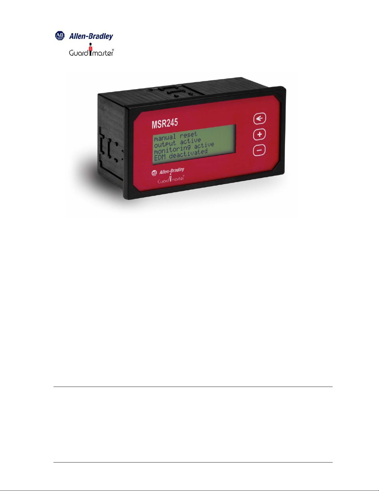
The MSR245 Display Module is connected to an MSR200 Safety System to provide a
local display of operational status and functioning of the system. The MSR245 is
connected via an RS-232 serial interface to an MSR240 Communication Module
integrated with the System. The Module has a 4-line x 20-character LCD display. Using
its 3 function key-switches, the configuration of external circuits and the operating
conditions of the System can read conveniently. The MSR245 requires 24V DC (+10%, 20%) supply voltage. The power supply and RS-232 connections are made through a
terminal block.
The Module’s LCD display has LED back-lighting, which is automatically switched on
whenever a key-switch is activated, and also automatically switched off after 5 minutes if
there is no operator interaction during that time. The RS-232 interface is electrically
isolated from the power supply circuit, with an isolation rating of 2 KV. The RS-232
interface has a fixed data rate of 4800 baud, and uses a serial communication protocol
compatible with the MSR240.
MSR245-manual-doc page 1 of 6
Page 2
MSR245 Manual 2
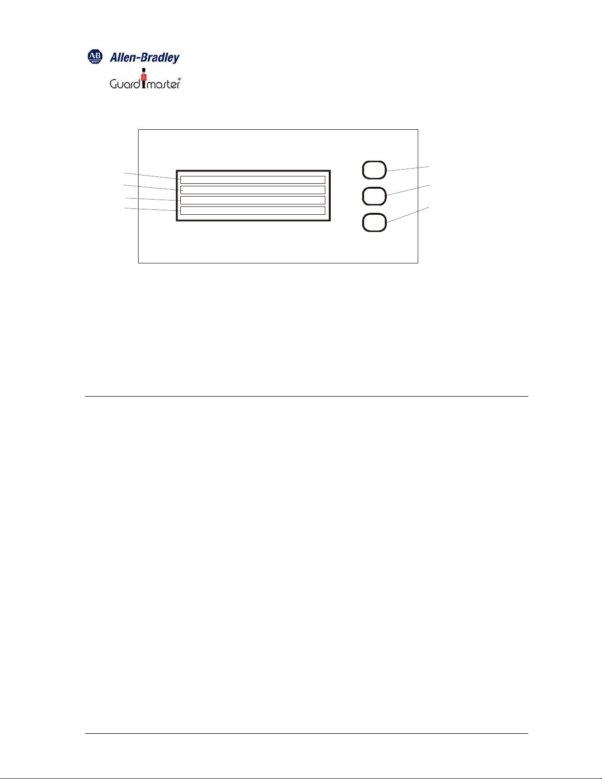
MSR245
4
5
6
7
1. Key-switch: display-reset
2. Key-switch: forward
3. Key switch: backward
4. Display line1
5. Display line2
Front panel MSR245
Key-switches 2 and 3 are used to select the various display menus. After the System is
switched on, and the MSR245 receives valid data from the MSR240, the Display Module
shows the following information:
Line 1: Automatic re-set (or) Manual re-set
6. Display line3
7. Displayline4
<
_
+
_
1
2
3
Line 2: Output active (or) Output
deactivated
Line 3: System ready (or) Monitoring
active (or) EDM circuit open
Line 4: Dynamic EDM (or) Static EDM
This is the default menu, to which the MSR245 can be re-set at any time by pressing “←”
(key-switch 1). Press “+” (key-switch 2) to step to the next menu option, or “-” (key-switch
3) to step to the previous menu option
MSR245-manual-doc page 2 of 6
Page 3

MSR245 Manual 3
The following menu display indicates the type and insertion position of the input modules
included in the MSR200 System at the time (Note: only input modules are indicated):
Line 1: Basic Module or Input Module
1…..10
Line 2: MSR210 Emergency Stop (or)
MSR211
Light Curtain (or) MSR220
Emergency Stop Module (or)
MSR221 Light Curtain
Line 3: Input 1: 1-, 2-, or 3-channel
Line 4: Input 2: 1-, 2-, or 3-channel
If an input to the MSR200 System is interrupted the displayed menu changes
automatically, to show the following:
Line 1: Basic Module or Input Module
1…..10
Line 2: Input 1 or Input 2 (standard text)
Line 3: Output tripped (standard text)
Line 4: Output active or output deactivated
If tripping occurs due to a mat safety switch or a cross-fault, the following text is
displayed:
Line 1: Mat safety switch (or)
Line 2: Cross-fault
Line 3: Tripped
Line 4: Output active or output deactivated
After tripping occurs, “←” (key-switch 1) must be pressed to revert to normal operating
condition.
Note: the display always shows information relating to the most recent tripping
occurrence, over-writing that of any previous tripping occurrence.
MSR245-manual-doc page 3 of 6
Page 4

MSR245 Manual 4
In addition to those described up to this point, the following additional diagnostic menu
options will also be displayed when such conditions occur:
Condition
Displayed text
Received data missing Receiving no data
Fault in an output module EDM circuit fault
Modules configuration changed
Y40 circuit fault
during system operation
MSR200 system internal fault Internal fault
Every fault occurrence indicated by the MSR245 must be acknowledged by pressing “←”
(key-switch 1).
Fault Indication Text Programming
For the indication of fault conditions, text of up to 3 lines x 20 characters for each input
can programmed by the user. Any characters can be used for such text. This text is
stored in an internal EEPROM, which can be re-written up to 1 million times, and can
retain stored data for at least 40 years. A software package makes it easy to enter and
edit the fault indication text on a PC, and upload it to the Module.
Fault Indication Text Programming Software
The fault indication text of the MSR245 is programmed using a PC connected to it via the
RS-232 serial interface. The MSR240 has to be disconnected for this procedure.
PC system requirements:
• Windows 95 / 98 / ME or Windows NT / 2000 / XP
• An uncommitted RS-232 serial port
The PC has to be connected to the MSR245 via a standard serial connection cable (not
supplied with the unit)
MSR245-manual-doc page 4 of 6
Page 5

MSR245 Manual 5
Installing the software:
• Create a new folder on the hard disk drive
Download the program files (MSR245_P1*.EXE and MSR245PROG.INI) from the
Rockwell Webpage: http://www.ab.com/
> Safety > Prod-Directory > Safety control relays
• The programmed settings are stored in the initialization file MSR245PROG.INI, and
automatically loaded when the program (MSR245_P1*.EXE) next executed.
The programming software makes it easy to select the settings and enter / edit the
display text through dialog boxes and tabbed panes within them:
• Through the main dialog box:
• Text to be displayed by the MSR245 can be entered, saved on the PC’s hard disk
drive, and printed
• The COM port and display text language (English or German) can be selected
• Programming data can be sent through the serial interface to the MSR245, which
is then set to execute the new program.
• Through the smaller dialog box on the side:
• Display text for each of the individual inputs can be edited by selecting the
corresponding tabbed pane
• The display text can be reviewed, after it is entered and edited
Programming and Editing the Display Text
• Run the programming software (MSR245_P1*.EXE)
• Select the language setting (English or German). The standard text in the selected
language will appear automatically on the screen. If the language of the standard text
is to be changed, in the dialog box File / New select the new language. The standard
text blocks will now appear in the individual text boxes, and can be edited as the user
wants. The selection of the language of the standard text is important because the
text that cannot be edited (e.g., “Auto-start”, “Output active”, etc.) will appear in the
selected language during normal operation of the MSR245.
NOTE: Confirm the standard text before editing, otherwise that which has
already been entered will be deleted
• After the editing is all done, the text can be reviewed by scrolling through the text box.
The text can now be saved, giving it the file-name extension “.txt”. This file can be
opened at a later time for uploading to the MSR245. In such a case, the display text
blocks from this file are used without further editing.
• The MSR245 can be programmed after all the display text blocks are edited and
confirmed. In the Settings dialog box, select the COM port to be used for the serial
interface to the MSR245.
• Press the “
←” and “-” key-switches (1 and 3). This will cause the text “Program-Mode”
to appear on the display, indicating that the MSR245 is now ready for programming.
Pressing “
←” alone at any time after this will cause the MSR245 to exit the
programming mode.
• The display is programmed through the menu option “Download / Start” . This causes
the data to be uploaded from the PC to the MSR245. A progress monitoring display
indicates the programming process status. When the data transfer is finished, the
MSR245-manual-doc page 5 of 6
Page 6

MSR245 Manual 6
MSR245 automatically reverts to its default display mode, and indicates ”Receiving no
data”.
• The text to be displayed by the MSR245 can be checked before the Module is put into
actual operation. To do this, click on the “Download” button or the “Download/Start”
menu option. This causes the PC to send data to the MSR245, simulating an MSR200
Emergency Stop System. After a short delay, this data appears on the MSR245
display.
• The buttons on the right of the “Check” tabbed pane can be used to simulate
operating conditions: Auto Start / Manual Start, EDM active / EDM deactivated, etc.
On the left side, click no interrupt. On the right side, click the different alarm / fault
conditions. Some alarms show (Å) after its name. The display reset switch must be
pressed after de-selecting the alarm.
• The test mode can be terminated by clicking on the “Download / Cancel” menu option.
Specifications
Supply voltage: 24 V
DC
Power consumption: Approximately 500 mW
Operating temperature: - 5
Storage temperature: -25
O
C to + 55 OC
O
C to + 70 OC
Protection class (per DIN VDE 0470-1): Terminals: IP20. Housing: IP40
Terminals Terminal box with wire protection
Wire cross section 2.5 mm
2
Serial data interface: RS-232, 4800 baud
Drg No: 57600/ Issue No: 1 Feb. 05
MSR245-manual-doc page 6 of 6
 Loading...