

Page 1
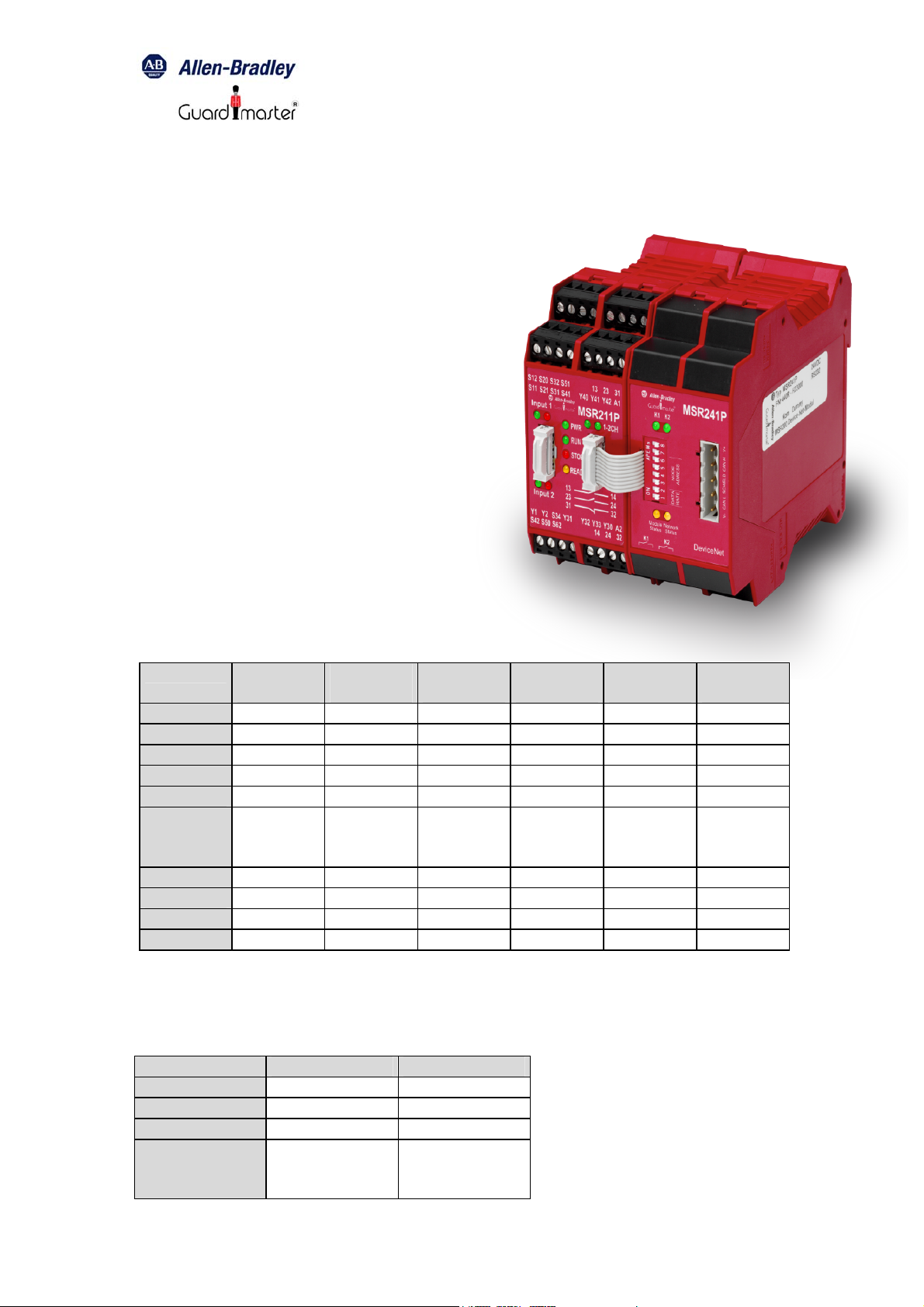
MSR241 DeviceNet for Safety System MSR200
1
______________________________________________________________
Installation Instructions MSR241
Installing MSR241
Follow theses steps, to install the MSR241
module:
1. Set the Node Address and the Baud
rate on the module.
2. Connect the MSR241 with the safety
system MSR200 via ribbon cable.
3. Connect the relay outputs
4. Connect the DeviceNet Cable.
5. Communicate with the MSR241
module.
These steps are explained in detail in the
following procedures.
Set the Node Address and Baud
Rate on the module
The address can be set between 00 and 63.
Address Dip
switch 8
0 off off off off off off
1 off off off off off on
2 off off off off on off
3 off off off off on on
4 off off off on off off
.
.
.
60 on on on on off off
61 on on on on off on
62 on on on on on off
63 on on on on on on
.
.
.
The baud rate can be set to:
125kB, 250kB, 500kB
Baud rate Dip switch 2 Dip switch 1
125kB off off
250kB off on
500kB on off
Invalid
(Module Status
LED solid red)
Dip
switch 7
.
.
.
on on
Dip
switch 6
.
.
.
Dip
switch 5
.
.
.
Dip
switch 4
.
.
.
Dip
switch 3
.
.
.
Page 2
MSR241 DeviceNet for Safety System MSR200
2
______________________________________________________________
Connect the MSR241 with the safety system MSR200 via
ribbon cable
The MSR241 mount to a panel or DIN rail, which must be grounded before
installing the module.
Connect the MSR241 either to the Basic module or to an output extension
module on the right side of the MSR200 safety system via ribbon cable.
The terminator for the EDM loop is integrated in the MSR241.
Connect the relay outputs
If you want to use the relay outputs of the MSR241 connect them to your
application.
Connect the DeviceNet Cable
Refer to following information when connecting the DeviceNet wire to the
MSR241.
1. Connect the DeviceNet cable (drop line) to the unsealed DeviceNet
terminal connector.
2. Connect the terminal connector to the module. Use the side screws on
the terminal connector to fasten it to the module.
IMPORTANT
Pin Number Wire Color Abbreviation Description
1 Black V- Power return
2 Blue CAN_L Data line (CAN Low)
3 Clear Shield Between cable jacket and wire
4 White CAN_H Data line (CAN High)
5 Red V+ Positive voltage (hot)
The bus cable must be terminated with a resistor (121 Ω / +/- 1% / 0,25W).
The resistor is contacted with CAN_H and CAN_L.
Page 3

MSR241 DeviceNet for Safety System MSR200
3
______________________________________________________________
Communicate with the MSR241 module
To transfer data from MSR241 to the D-Net it is required to upload the
“Electronic Data Sheet” (EDS file). This file is available for free download on
the A-B web-page: http://www.ab.com/networks/eds/ >Product Name
MSR241P
The name of the EDS file is: 0001000C00A30100.eds
The MSR241 operates as a “Group 2 only slave” device and supports UCMM.
The MSR241 is exchanged with the master through a polled, cyclic or change
of state connection.
Polled – Masters initiates communication by sending its polled I/O messages
to the MSR241 module. The module consumes the message, updates any
outputs, and produces a response. The response contains the input data.
Cyclic – allows configuration of the module as an I/O client. The module will
produce and consume its I/O cyclically at the rate configured.
Change of state – production occurs when an input changes. If no input
change occurs within the expected packet time, a heartbeat production
occurs. This heartbeat production tells the scanner module that the MSR241
is alive and ready to communicate. Consumption occurs when data changes
and the master produces new output data to the module.
The module produces 4 bytes and consumes 1 byte for outputs.
Page 4
MSR241 DeviceNet for Safety System MSR200
4
______________________________________________________________
Byte Definitions
The table below shows the definition of the module
Consumed output byte
Bit High Low
00 K1 energized K1 de-energized
01 K2 energized K2 de-energized
02 Reserved Reserved
03 Reserved Reserved
04 Reserved Reserved
05 Reserved Reserved
06 Reserved Reserved
07 Reserved Reserved
Produced Input bytes
Input byte 1: Configuration and status of MSR210 / MSR211
Bit High Low
00 Device ready Monitoring active
01 Interrupt of any input All inputs valid
02 Cross loop detected No cross loop
03 Automatic reset Supervised reset
04 Relay-output active (Safety system) Relay-output not active (Safety system)
05 EDM dynamic EDM static
06 EDM-loop open EDM-loop closed
07 Internal fault or no basic module
connected
Input-byte2: Status of Inputs of basic module and extension modules 1, 2 and 3
Bit High Low
00 Basic module, input 1 interrupted Basic module, input 1 valid
01 Basic module, input 2 interrupted Basic module, input 2 valid
02 Extension module 1, input 1
interrupted
03 Extension module 1, input 2
interrupted
04 Extension module 2, input 1
interrupted
05 Extension module 2, input 2
interrupted
06 Extension module 3, input 1
interrupted
07 Extension module 3, input 2
interrupted
No internal fault and basic module
connected
Extension module 1, input 1 valid (or
module not existent)
Extension module 1, input 2 valid (or
module not existent)
Extension module 2, input 1 valid (or
module not existent)
Extension module 2, input 2 valid (or
module not existent)
Extension module 3, input 1 valid (or
module not existent)
Extension module 3, input 2 valid (or
module not existent)
Page 5

MSR241 DeviceNet for Safety System MSR200
5
______________________________________________________________
Input-byte3: Status of Inputs of Extension modules 4, 5, 6 and 7
Bit High Low
00 Extension module 4, input 1
interrupted
01 Extension module 4, input 2
interrupted
02 Extension module 5, input 1
interrupted
03 Extension module 5, input 2
interrupted
04 Extension module 6, input 1
interrupted
05 Extension module 6, input 2
interrupted
06 Extension module 7, input 1
interrupted
07 Extension module 7, input 2
interrupted
Input-byte4: Status of Inputs of Extension modules 8, 9 and 10
Bit High Low
00 Extension module 8, input 1
interrupted
01 Extension module 8, input 2
interrupted
02 Extension module 9, input 1
interrupted
03 Extension module 9, input 2
interrupted
04 Extension module 10, input 1
interrupted
05 Extension module 10, input 2
interrupted
06 Reserved Reserved
07 Reserved Reserved
Extension module 4, input 1 valid (or
module not existent)
Extension module 4, input 2 valid (or
module not existent)
Extension module 5, input 1 valid (or
module not existent)
Extension module 5, input 2 valid (or
module not existent)
Extension module 6, input 1 valid (or
module not existent)
Extension module 6, input 2 valid (or
module not existent)
Extension module 7, input 1 valid (or
module not existent)
Extension module 8, input 2 valid (or
module not existent)
Extension module 8, input 1 valid (or
module not existent)
Extension module 8, input 2 valid (or
module not existent)
Extension module 9, input 1 valid (or
module not existent)
Extension module 9, input 2 valid (or
module not existent)
Extension module 10, input 1 valid (or
module not existent)
Extension module 10, input 2 valid (or
module not existent)
Page 6

MSR241 DeviceNet for Safety System MSR200
6
______________________________________________________________
Implemented DeviceNet Objects
Mandatory Objects
Object Name Class
Identify Object 01h
Message Router Object 02h
DeviceNet Object 03h
Connection Object 05h
Acknowledge Handler Object 2Bh
Device Configuration Object 64h
Identity Object, Class 01h
Class Attributes (0)
ID Name Service Description Value Type
1 Revision Get_Attribute_Single Object revision 1 1 UINT
Instance Attributes (1)
ID Name Service Description Value Type
1 Vendor ID Get_Attribute_Single Identification of each vendor by
2 Device
Type
3 Product
Code
4 Revisions Get_Attribute_Single Revision of the item the Identity
5 Status Get_Attribute_Single Summary Status of the Device
6 Serial
Number
7 Product-
name
Get_Attribute_Single Indication of general type of product 000Ch UINT
Get_Attribute_Single This is a code assigned by the
Get_Attribute_Single Serial Number of the device UDINT
Get_Attribute_Single Human readable identification “MSR241P”
number
Vendor to describe the device
Object represents
bit0: Module Owed. A master has
allocate the module
bit1: reserved
bit2: Configured
bit3 - 7: reserved
bit8: Minor recoverable fault
bit9: Minor recoverable fault
bit10: Major recoverable fault
bit11: Major recoverable fault
bit12 - 15: reserved
0001h
00A3h
1.31 Array of:
WORD
UINT
UINT
USINT
USINT
SHORT_
STRING
Massage Router Object, Class 02h
Class Attributes (0)
ID Name Service Description Value Type
1 Revision Get_Attribute_Single Object revision 1 1 UINT
Page 7

MSR241 DeviceNet for Safety System MSR200
7
______________________________________________________________
DeviceNet Object, Class 03h
Class Attributes (0)
ID Name Service Description Value Type
1 Revision Get_Attribute_Single Object revision 2 2 UINT
Instance Attributes (1)
ID Name Service Description Def, Min, Max Type
1 MAC ID Get_Attribute_Single Currently used MacID Switches 0, 63 USINT
2 Baud rate Get_Attribute_Single Currently used baudrate
5 Allocation
Informatio
n
6 MAC ID
Switch
Changed
7 Baud Rate
Switch
Changed
8 MAC ID
Switch
Value
9 Baud Rate
Switch
Value
Get_Attribute_Single Allocation Choice byte
Get_Attribute_Single The Node Address Switches have
Get_Attribute_Single The Baud Rate Switches have
Get_Attribute_Single Actual value of Node Address
Get_Attribute_Single Actual value of Baud Rate Switches Range: 0-3 USINT
0 = 125kB
1 = 250 kB
2 = 500kB
Master´s MAC ID
changed since the last power-up /
reset
changed since the last power-up /
reset
Switches
Switches, 0, 2 USINT
N/A Struct of:
0 = no change
1 = Change since last reset
or power-up
0 = no change
1 = Change since last reset
or power-up
Range: 0-63 USINT
BYTE
USINT
BOOL
BOOL
Assembly Object, Class 04h
Instance Attributes, Instance/Connection Point (64h)
ID Name Service Description Value Type
3 Data Get_Attribute_Single Data produced by MSR241 to the
master
Instance Attributes (96h)
ID Name Service Description Def, Min, Max Type
3 Data Get_Attribute_Single Data consumed by MSR241 from the
master
Array of byte
Array of byte
Page 8

MSR241 DeviceNet for Safety System MSR200
8
______________________________________________________________
DeviceNet Connection Object, Class 05h
Class Attributes (0)
ID Name Service Description Value Type
1 Revision Get_Attribute_Single Object revision 1 1 UINT
Explicit Connection Instance (1, 2, 4 & 10…14)
Instance 1 = Explicit messaging connection (Predefined in DeviceNet object)
Instance 2 = Polled connection / COS / Cyclic consuming connection)
Instance 4 = COS / Cyclic producing connection
Instance 10 - 14 = Explicit connection (UCMM allocated)
ID Name Service Description Value Type
1 State Get_Attribute_Single Object State
2 Instance
Type
3 Transport
Class
Trigger
4 Produced
Cnxn ID
5 Consumed
Cnxn ID
6 Initial
Comm
Characteri
stics
7 Produced
Connectio
n Size
8 Consumed
Connectio
n Size
9 Expected
Packet
Rate
C Watchdog
Timeout
Action
D Produced
Connectio
n Path
Length
E Produced
Connectio
n Path
F Consumed
Connectio
n Path
Length
10 Consumed
Connectio
n Path
Get_Attribute_Single Explicit messaging connection 0 USINT
Get_Attribute_Single Server / Transport Class 3 83h BYTE
Get_Attribute_Single CAN ID for transmission UINT
Get_Attribute_Single CAN ID for reception UINT
Get_Attribute_Single The message group over which the
Get_Attribute_Single Maximum number of bytes
Get_Attribute_Single Maximum number of bytes received
Get_Attribute_Single
Set_Attribute_Single
Get_Attribute_Single Defines how to handle inactivity /
Get_Attribute_Single Number of bytes in the
Get_Attribute_Single No connection path EPATH
Get_Attribute_Single Number of bytes in the Consumed
Get_Attribute_Single No connection path EPATH
0: Non existent
1: Configuring
2: Waiting for Connection ID
3: Established
4: Timed out
communication occurs
transmitted across the connection
across the connection
Timing associated with this
connection (2500ms)
watchdog timeouts
1: Auto delete
3: Deferred delete
Produced_connection_path attribute
connection path instance
USINT
BYTE
0100h UINT
0100h UINT
09C4h UINT
1 USINT
0 UINT
0 UINT
Page 9

MSR241 DeviceNet for Safety System MSR200
9
______________________________________________________________
Polled I/O Connection Instance (2)
ID Name Service Description Value Type
1 State Get_Attribute_Single Object State
2 Instance
Type
3 Transport
Class
Trigger
4 Produced
Cnxn ID
5 Consumed
Cnxn ID
6 Initial
Comm
Characteri
stics
7 Produced
Connectio
n Size
8 Consumed
Connectio
n Size
9 Expected
Packet
Rate
C Watchdog
Timeout
Action
D Produced
Connectio
n Path
Length
E Produced
Connectio
n Path
F Consumed
Connectio
n Path
Length
10 Consumed
Connectio
n Path
11 Production
Inhibit
Time
Get_Attribute_Single I/O connection 1 USINT
Get_Attribute_Single Server/Transport Class 0
Get_Attribute_Single CAN ID for transmission UINT
Get_Attribute_Single CAN ID for reception UINT
Get_Attribute_Single Produces over message group 1
Get_Attribute_Single Maximum number of bytes
Get_Attribute_Single Maximum number of bytes received
Get_Attribute_Single
Set_Attribute_Single
Get_Attribute_Single
Set_Attribute_Single
Get_Attribute_Single Number of bytes in the
Get_Attribute_Single Application obj. producing data on
Get_Attribute_Single Number of bytes in the
Get_Attribute_Single Specifies the application object(s)
Get_Attribute_Single Minimum time between new data
0: Non existent
1: Configuring
2: Waiting for Connection ID
3: Established
4: Timed out
Server/Transport Class 0
Consumes over message group 2
Does not produce
Consumes over message group 2
transmitted across the connection
across the connection
Timing associated with this
connection
0: Transmission timeout
Produced_connection_path attribute
this connection
Consumed_connection_path
attribute
that are to receive the data
consumed by this connection object
production
USINT
80h
83h
01h
F1h
4 UINT
1 UINT
0 UINT
0 USINT
0007h (Polled)
0000h (COS / Cyclic)
20h, 04h, 25h, 64h, 00h,
30h, 03h
7 UINT
20h, 04h, 25h, 96h, 00h,
30h, 03h
0 UINT
BYTE
BYTE
UINT
EPATH
EPATH
Page 10

MSR241 DeviceNet for Safety System MSR200
10
______________________________________________________________
Change of state / Cyclic (4) (Acknowledged)
ID Name Service Description Value Type
1 State Get_Attribute_Single Object State
2 Instance
Type
3 Transport
Class
Trigger
4 Produced
Cnxn ID
5 Consumed
Cnxn ID
6 Initial
Comm
Characteri
stics
7 Produced
Connectio
n Size
8 Consumed
Connectio
n Size
9 Expected
Packet
Rate
C Watchdog
Timeout
Action
D Produced
Connectio
n Path
Length
E Produced
Connectio
n Path
F Consumed
Connectio
n Path
Length
10 Consumed
Connectio
n Path
11 Production
Inhibit
Time
Get_Attribute_Single I/O connection 1 USINT
Get_Attribute_Single Defines behavior of the connection 00h = Cyclic
Get_Attribute_Single CAN ID for transmission UINT
Get_Attribute_Single CAN ID for reception UINT
Get_Attribute_Single Produces over message group 1,
Get_Attribute_Single Number of bytes transmitted across
Get_Attribute_Single Consumes o Byte on this connection 0 UINT
Get_Attribute_Single
Set_Attribute_Single
Get_Attribute_Single 0: Transmission timeout 0 USINT
Get_Attribute_Single Number of bytes in the Produced
Get_Attribute_Single Assembly Object, Instance 100,
Get_Attribute_Single Number of bytes in the Consumed
Get_Attribute_Single Acknowledge Handler Object,
Get_Attribute_Single Minimum time between new data
0: Non existent
1: Configuring
2: Waiting for Connection ID
3: Established
4: Timed out
Does not consume.
Produces over message group 1,
Consumes over message group 2
the connection
Timing associated with this
connection
connection path attribute
Attribute 3 is producing the data
connection path instance
Instance 1
production
USINT
03h = Cyclic + ACK
10h = COS
13 = COS + ACK
0Fh
01h
4 UINT
0 UINT
0007h UINT
20h, 04h, 25h, 64h, 00h,
30h, 03h
0007h (no ACK)
0005h (ACK)
20h, 2Bh, 25h, 01h, 00h
0 UINT
BYTE
BYTE
EPATH
UINT
EPATH
Page 11

MSR241 DeviceNet for Safety System MSR200
11
______________________________________________________________
Acknowledge Handler Object, Class 2Bh
Class Attributes (0)
ID Name Service Description Value Type
1 Revision Get_Attribute_Single Revision 1 1 UINT
Instance Attributes (1)
ID Name Service Description Value Type
1 Acknowled
ge Timer
2 Retry Limit Get_Attribute_Single
3 Producing
Connectio
n Instance
Device Configuration Object, Class 64h
Instance Attributes (1)
ID Name Service Description Def, Min, Max Type
1 Number of
extension
modules
Get_Attribute_Single
Set_Attribute_Single
Set_Attribute_Single
Get_Attribute_Single Connection instance, which contains
Get_Attribute_Single Number of input extension modules
Time (in ms) to wait for acknowledge
before re-sending
Number of ACK timeouts before retry
reached event
the path of the producing I/O
application object, which will be
notified of ACK Handler events
of the safety system MSR200
16 UINT
1 USINT
4 UINT
0, 0, 10 BYTE
Page 12

MSR241 DeviceNet for Safety System MSR200
12
______________________________________________________________
Troubleshoot with Indicators
The MSR241 has the following indicators:
• Module status indicator
• Network status indicator
• Output status indicators K1 and K2
Module Status Indicator
Indication Status
Off Device not powered
Green Device operational
Flashing green Device needs commissioning due to missing or incorrect
configuration, MSR241 not connected to the Safety
system MSR210
Red Unrecoverable fault
Flashing red Minor fault recoverable, baud rate switches are invalid, MAC
ID or Baud Rate switches are changed while on line or since
reset / power-up
Network Status Indicator
Indication Status
Off Device not powered / Not online
Green Link OK, On line, Connected
Flashing green On line, Not connected
Red Critical link failure
Flashing red Connection timeout
Output Status Indicator K1
Indication Status
Off K1 de-energized
Green K1 energized
Output Status Indicator K2
Indication Status
Off K2 de-energized
Green K2 energized
Page 13

MSR241 DeviceNet for Safety System MSR200
13
______________________________________________________________
Specifications
Output specification K1, K2
Nominal switching capacity (resistive
load)
Max. switching power (resistive load) 60W
Max. switching voltage 220V DC
Max. switching current 2A
Min. switching capacity 10µA 10mV DC
UL/CSA rating 2A 30V DC
General Specifications
Indicators
Communication rate
Max. length of fieldbus segment
Isolation
Output to DeviceNet
Output to Output
DeviceNet Power
Voltage
Current
Temperature
Drg No: 57602/ Issue No: 0 Feb. 04
2A 30V DC
0.3A 110V DC
0.5A 125V DC
Module Status red/green
Network Status red/green
Output Status K1, K2 green
125 kBaud, 250kBaud, 500 kBaud
100m … 500m (depends on baud rate /
on the cable)
500V ac/60s
500V ac/60s
11 – 25V dc
170mA maximum
-5°C – 50°C
 Loading...