

Page 1
Communication Module MSR240 1
Manual and Protocol Description
Overview
The MSR240 Communication Module serves as an interface between a MSR210 or
MSR211 Basic Module and a standard serial data communication line. The MSR240
transmits data relating to the operational status and fault conditions of, and the external
electrical circuits monitored by, the MSR200 System. The MSR240 is connected via a
10-core flat cable to an MSR210/211 Basic Module or MSR230 Extension Module. The
two processors in the Basic Module exchange data cyclically over a serial system bus
(SPI). Data is transferred to the MSR240 via the flat cable connection, through a driver
circuit stage. The MSR240 converts the data into RS232 and RS485 transmission levels
with appropriate serial data protocols, so that it can be transferred to an external device
(e.g. Display Module) or system (PC or PLC).
The MSR240 is available in three versions:
• 440R-H123181: with RS232 serial interface
• 440R-H123182: with RS485 serial interface
• 440R-H123183: with RS232 and RS485 serial interfaces
The MSR240 is housed in a 17.5mm wide DIN rail mounting enclosure.
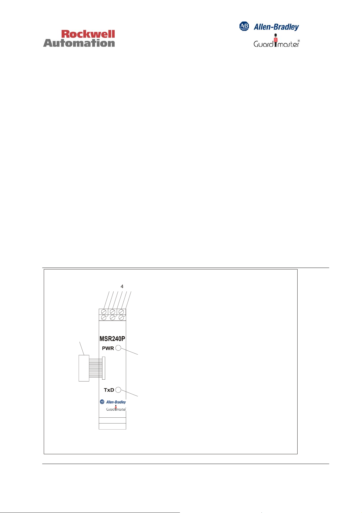
The serial data communication connections are made through one or two 3-way plug-in
screw terminal blocks.
123 56
1: T erminal A (RS485)
ABGND
TxD GND
7
Á
2: Terminal Cable Shield (RS232)
3: Terminal B (RS485)
4: Terminal TxD (RS232)
5: Terminal GND (RS485)
8
6: Terminal GND (RS232)
7: Interface Connection to MSR210P or
MSR211P Basic module
8: Power “on” LED
9
9: RS232 / RS485 transmit annunciator LED
Page 2
Communication Module MSR240 2
TxD
GND
A
B
GND
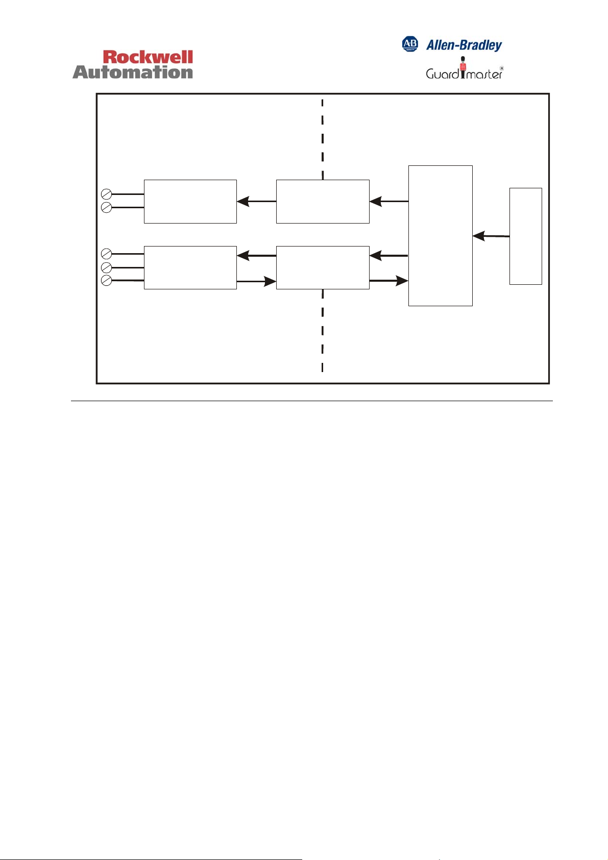
Blockdiagram
Signal Level
Conversion
RS232
Signal Level
Conversion
RS485
Electrical
Isolation
Electrical
Isolation
The following data relating to the MSR200 System is transmitted:
• Configuration and device status
• Connected input module types and their order of connection
• Fault diagnostic information
µC
MSR200 System
Port Terminal
Page 3

Communication Module MSR240 3
RS232 Interface Description
Data blocks are transmitted continuously through the RS232 interface, at intervals of
approximately 1 sec. The MSR240 is intended to transmit data to an MSR245 Display
Module, or to a PC. The Baud rate is fixed at 4800
The RS232 protocol uses a 16-byte data block, structured as follows:
1 Start byte: 02
2 Device status: Bit 0: = 1: Unit ready for start. / = 0: Not ready / busy
Bit 1: = 1: Stop signal. / = 0: Inputs OK
Bit 2: = 1: Cross-fault. / = 0: No cross-fault
Bit 3: = 1: Auto start. / = 0: Manual start
Bit 4: = 1: Relay energised. / = 0: Relay de-energised
Bit 5: = 1: Feedback loop dynamic. / = 0: Feedback loop
static
Bit 6: = 1: Feedback loop open if unit is "Ready"
Bit 7: = 1
3 Fault diagnostics: Bit 0: = 1: System bus (SPI) failure. / = 0: ….OK
Bit 1: = 1: Oscillator failure. / = 0: ….OK
Bit 2: = 1: Relay transistor failure. / = 0: ….OK
Bit 3: = 1: Relay contact failure. / = 0: ….OK
Bit 4: = 1: Feedback circuit fault. / = 0: ….OK
Bit 5: = 1: Y40 circuit failure. / = 0: ….OK
Bit 6: = 1: Bus termination plug missing. / = 0: ….OK
Bit 7: = 1
4 - 14 Input modules: activation and wiring:
Bit 0: = 1: Emergency stop (or failure): Input 1
Bit 1: = 1: Emergency stop (or failure): Input 2
Bit 2: = 1: MSR220 Module. / = 0: MSR221 Module
Bit 3: = 1 0 1
Bit 4: = 0 1 1
1- 2- 3-channel detection: Input 2
Bit 5: = 1 0 1
Bit 6: = 0 1 1
1- 2- 3-channel detection: Input 1
Bit 7: = 1
15 Control byte: XOR – conjunction of Bytes 2 through 14
16 End byte: 03
Page 4

Communication Module MSR240 4
RS485 Interface Description
Data relating to the MSR200 System is transmitted via the RS485 channel only in
response to a command characters string received by the MSR240:
Character 1 Start byte = 2
Character 2 Address1 = 48..51 (0..3) [Address x 10]
Character 3 Address0 = 48..57 (0..9) [Address x 1]
Character 4 Function = 49 (1) [1 = Function: send character]
Character (5) XOR-linkage of Address1, Address0 and Function (optional)
Character 5 (6) End byte = 3
Addresses in the range 0 to 31 can be set via five DIP switches. Addresses below 10
must start with a zero.
Function setting is fixed at 49 (1) and is the code to send data.
Baud rate can be selected via two DIP switches from the following values:
• 2400 baud Bit 0 = OFF Bit 1 = OFF
• 4800 baud Bit 0 = OFF Bit 1 = ON
• 9600 baud Bit 0 = ON Bit 1 = OFF
• 19200 baud Bit 0 = ON Bit 1 = ON
RS485 Interface: DIP Switch Settings
ON = XOR check enabled
Address bit 4
ONON
Address bit 3
Address bit 2
Address bit 1
Address bit 0
Baud rate bit 1
Page 5

Communication Module MSR240 5
Baud rate setting (RS485)
Baud rate Bit 0 Bit 1
2400 OFF OFF
4800 OFF ON
9600 ON OFF
19200 ON ON
Address setting (RS485)
Address Bit 0 Bit 1 Bit 2 Bit 3 Bit 4
31 OFF OFF OFF OFF OFF
30 ON OFF OFF OFF OFF
29 OFF ON OFF OFF OFF
28 ON ON OFF OFF OFF
27 OFF OFF ON OFF OFF
26 ON OFF ON OFF OFF
25 OFF ON ON OFF OFF
24 ON ON ON OFF OFF
23 OFF OFF OFF ON OFF
22 ON OFF OFF ON OFF
21 OFF ON OFF ON OFF
20 ON ON OFF ON OFF
19 OFF OFF ON ON OFF
18 ON OFF ON ON OFF
17 OFF ON ON ON OFF
16 ON ON ON ON OFF
15 OFF OFF OFF OFF ON
14 ON OFF OFF OFF ON
13 OFF ON OFF OFF ON
12 ON ON OFF OFF ON
11 OFF OFF ON OFF ON
10 ON OFF ON OFF ON
9 OFF ON ON OFF ON
8 ON ON ON OFF ON
7 OFF OFF OFF ON ON
6 ON OFF OFF ON ON
5 OFF ON OFF ON ON
4 ON ON OFF ON ON
3 OFF OFF ON ON ON
2 ON OFF ON ON ON
1 OFF ON ON ON ON
0 ON ON ON ON ON
Page 6

Communication Module MSR240 6
Via RS485 following protocol is transmitted:
1. Start byte: 02
2. Address: Address (0..31 dec)
3. Device Status: bit0: 1: device ready for start / 0: not ready for start (or already busy)
bit1: 1: Stop signal, 0: all Inputs OK
bit2: 1: Cross fault, 0: No cross fault
bit3: 1: auto start, 0: monitored Start
bit4: 1:
bit5: 1: EDM dynamic / 0: Feedback loop static
bit6: 1: Feedback loop open if unit is ready
bit7: 1
4. Input Status of Modules 1-3:
bit0: Stop signal Base Module Input 1
bit1: Stop signal Base Module Input 2
bit2: Stop signal EW1 Input1
bit3: Stop signal EW1 Input2
bit4: Stop signal EW2 Input1
bit5: Stop signal EW2 Input2
bit6: Crossfault on input signal lines
bit7: 1
5. Input Status of Modules 4-6:
bit0: Stop signal EW3 Input1
bit1: Stop signal EW3 Input2
bit2: Stop signal EW4 Input1
bit3: Stop signal EW4 Input2
bit4: Stop signal EW5 Input1
bit5: Stop signal EW5 Input2
bit6: internal failure
bit7: 1
6. Input Status of Modules 7-9:
bit0: Stop signal EW6 Input1
bit1: Stop signal EW6 Input2
bit2: Stop signal EW7 Input1
bit3: Stop signal EW7 Input2
bit4: Stop signal EW8 Input1
bit5: Stop signal EW8 Input2
bit6: unused
bit7: 1
7. Input Status of Modules 10-11:
bit0: Stop signal EW9 Input1
bit1: Stop signal EW9 Input2
bit2: Stop signal EW10 Input1
bit3: Stop signal EW10 Input2
bit4: unused
bit5: unused
bit6: unused
bit7: 1
8. XOR-Check: XOR-connection of Bytes 2 - 7 (optional)
9. (8.) End byte: 03
relay energised /
0:
de-energised
Page 7

Communication Module MSR240 7
Specifications:
Operating voltage: 24 VDC, supplied from MSR210P / MSR211P
Basic Module
Power consumption: Approx. 2W
Ambient temperature: -5°C to +55°C
Storage temperature: -25°C to +70°C
Protection class (per DIN VDE 0470-1): Terminals: IP20. Enclosure: IP40
Terminals Plug-in screw terminal blocks, box clamp type
Wire cross section 2.5 mm2 (max.)
Control circuit voltage 24 V
(nominal)
DC
Specifications RS232:
Baudrate 4800
Databits: 8
Parity: none
Stopbits: 1
Flowcontrol: none
Specifications RS485:
Baudrate 2400/ 4800/ 9600/ 19200
Databits: 8
Parity: none
Stopbits: 1
Flowcontrol: none
Drg No: 95302191/ Issue No: 1 May 05
 Loading...