

Page 1
Betriebsanleitung DEUTSCH
Lichtgittermodul MSR22LM
mit umschaltbaren Funktionen
Printed in G ermany, Dwg. No: 23992, EO: 0329, Is sue No: 3
ORIGINAL
Vor der Installation, dem Betrieb oder der Wartung des Geräts muss diese
Anleitung gelesen und verstanden werden.
GEFAHR
Gefährliche Spannung.
Lebensgefahr oder schwere Verletzungsgefahr.
Vor Beginn der Arbeiten, Anlage und Gerät spannungsfrei
schalten.
VORSICHT
Eine sichere Gerätefunktion ist nur mit zerti zierten Komponenten
gewährleistet!
Hinweise
Die hier beschriebenen Produkte wurden entwickelt, um als Teil einer
Gesamtanlage oder Maschine sicherheitsgerichtete Funktionen zu übernehmen. Ein komplettes sicherheitsgerichtetes System enthält in der Regel
Sensoren, Auswerteeinheiten, Meldegeräte und Konzepte für sichere Abschaltungen. Es liegt im Verantwortungsbereich des Herstellers einer Anlage
oder Maschine die korrekte Gesamtfunktion sicherzustellen.
Rockwell Automation ist nicht in der Lage, alle Eigenschaften einer Gesamtanlage oder Maschine, die nicht durch Rockwell Automation konzipiert
wurde, zu garantieren. Das Gesamtkonzept der Steuerung, in die das Gerät
eingebunden ist, ist vom Benutzer zu validieren. Rockwell Automation übernimmt auch keine Haftung für Empfehlungen, die durch die nachfolgende
Beschreibung gegeben bzw. impliziert werden. Aufgrund der nachfolgenden Beschreibung können keine neuen, über die allgemeinen
Rockwell Automation-Lieferbedingungen hinausgehenden, Garantie-,
Gewährleistungs- oder Haftungsansprüche abgeleitet werden.
Geräteeigenschaften
Entspricht
- Performance Level (PL) e und Kategorie 4 nach EN ISO 13849-1: 2008
- SIL-Anspruchsgrenze (SIL CL) 3 nach IEC/EN 62061
- Safety Integrity Level (SIL 3) nach IEC/EN 61508
- Kategorie 4 nach EN 954-1
Zum Anschluss von max.
- 3 BWS (berührungslos wirkende Schutzeinrichtung) 2-kanalig oder
- 2 BWS 2-kanalig und 2 Muting-Sensoren 1-kanalig oder
- 1 BWS 2-kanalig und 4 Muting-Sensoren 1-kanalig oder
- 2 BWS 2-kanalig und Schlüsselschalter für Taktumschaltung
- Zusätzlich: Start-Taster und Maschinenkontakt mit Leitungs schlusserkennung
Drahtbrucherkennung des BWS-Anschlusses
Ausgänge:
- 3 Schließer oder 2 Schließer und 1 Ö ner
- 2 Halbleiterausgänge, kurzschlussfest und überlastsicher
Multifunktionsgerät, umschaltbar über Drehschalter für die
Betriebsarten:
- Schutzbetrieb, z. B. Lichtvorhänge
- Schutzbetrieb mit Muting, z. B. Förderbänder
- Einstellung unterschiedlicher Signalfolgen der Muting-Sensoren
- Einstellbarkeit der max. zulässigen Mutingzeit
- Override-Funktion über Starttaster
- Taktbetrieb, z. B: Pressen
- Wahlweise 1, 2 oder 3 Takte
- Taktzahl-Einstellung wahlweise mit Schlüsselschalter
Geeignet für den Anschluss von BWS Typ 4 oder von getesteten
BWS Typ 2 gemäß IEC/EN 61 496-1, Querschlusserkennung in BWS
Mit Unter- und Überspannungserkennung und -signalisierung
Reaktionszeiten: max. 30 ms
LED-Anzeigen für RUN-Betrieb, Kanal 1/2
Sicherheitsbestimmungen
- Das Gerät darf nur von Personen installiert und in Betrieb genommen
werden, die mit dieser Betriebsanleitung und den geltenden Vorschriften
über Arbeitssicherheit und Unfallverhütung vertraut sind.
- Beachten Sie die VDE- sowie die örtlichen Vorschriften, insbesondere
hinsichtlich Schutzmaßnahmen.
- Der Berührungsschutz der angeschlossenen Elemente und die Isolation
der Zuleitungen sind für die höchste am Gerät anliegende Spannung
auszulegen.
- Durch Ö nen des Gehäuses oder eigenmächtige Umbauten erlischt
jegliche Gewährleistung.
- Montieren Sie das Gerät in einen Schaltschrank mit Schutzart IP 54 oder
besser; Staub und Feuchtigkeit können sonst zu Beeinträchtigungen
der Funktionen führen.
- Sorgen Sie an allen Ausgangskontakten bei kapazitiven und induktiven
Lasten für eine ausreichende Schutzbeschaltung.
- Die Sicherheitsfunktion muss mindestens einmal im Monat ausgelöst
werden.
Bestimmungsgemäße Verwendung
Das MSR22LM dient dem sicherheitsgerichteten Unterbrechen eines Sicherheitsstromkreises. Es kann im Schutz-, Muting- und Taktbetrieb zum Schutz
von Personen und Maschinen in Anwendungen mit Lichtgittern verwendet
werden.
Bei bestimmungsgemäßer Verwendung und Beachtung dieser Anleitung
sind keine Restrisiken bekannt. Bei Nichtbeachtung kann es zu Personenund Sachschäden kommen.
Praxishinweise
Vor dem Abnehmen der Platte an der Frontseite muss für einen Potential-
ausgleich gesorgt werden.
Bei Mutingbetrieb muss die Mutingleuchte den Angaben der
EN 61496-1 Abschnitt A7.4 entsprechen.
Wird eine BWS nicht benötigt, müssen jeweils 2 Brücken für jede nicht be-
nötigte BWS gemäß Bild 9 an die Anschlussklemmen S-1/S-2 und S-4/S-3
gesetzt werden.
Sicherheitshinweise
ACHTUNG!
Beim MSR22LM darf der Ö nerkontakt 31- 32 nur als Meldesignal
verwendet werden.
Nicht geeignet für Anlagen bei denen die BWS hintertretbar sein soll
Einstellungen am Gerät sind vom Fachpersonal im spannungslosen
Zustand durchzuführen.
Anschlussklemmen
Klemmenbezeichnung Signalbeschreibung
A1+ + / L
A2 - / N
S12, S14, S22, S24, S32, S34,
S42, S44, M1, M2
S21, S23, S31, S33, S33, S41, S43 Steuerausgänge
13, 14, 23, 24, 33, 34
31,32
48, 58 Halbleiter-Meldeausgang
X44
Steuereingänge
Schließer zwangsgeführt für
Freigabekreis
Ö ner zwangsgeführt für
Meldesignal
Freie Verbindungsklemme,
potentialfrei
Alle Anga ben in dieser Liste e ntsprechen dem t echnischen Stand z um Zeitpunkt de r Ausgabe.
Technische Ver besserungen un d Änderungen b ehalten wir uns jed erzeit vor.
1
Page 2
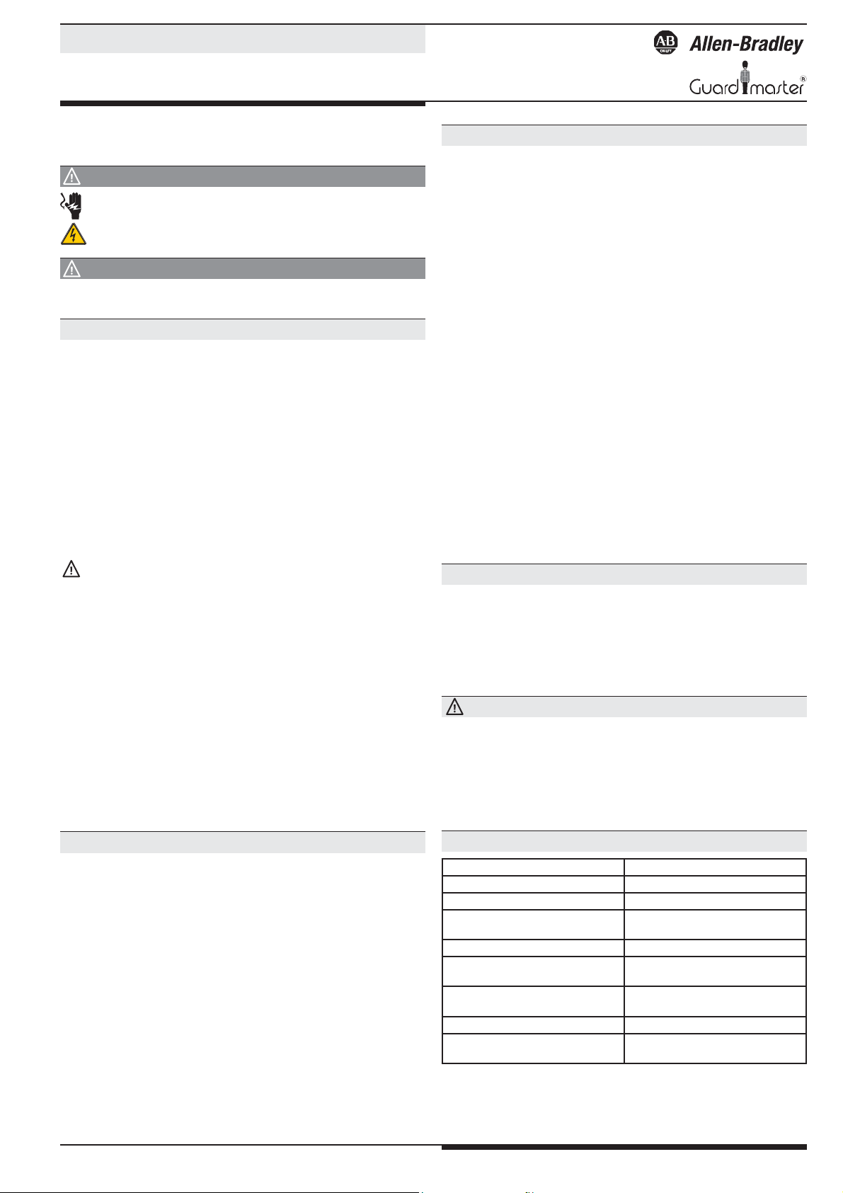
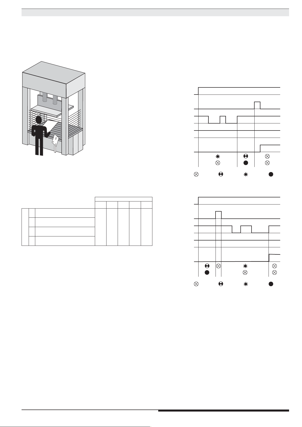
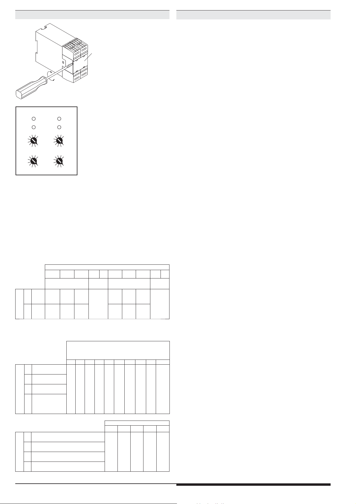
Geräteeinstellung
03
69
03
690369
03
69
ch1 ch2
10
1
M8015
Ansicht innen
g
g
Einstellbeispiel:
einzustellende Funktion:
Schutzbetrieb mit Muting,
Hand-Start, 4 Mutingsensoren),
max. 30 s Mutingzeit
Platte
Einstellung an den oberen beiden
M2347_a
Drehschaltern:
jeweils "5"
(für beide Prozessoren)
Einstellung an den unteren beiden
Drehschaltern:
jeweils "2"
(für beide Prozessoren)
Die Funktionseinstellung des MSR22LM erfolgt über 4 Drehschalter (Poti) hinter der oben abgebildeten Platte. Die Drehschalter "links" dienen zur Einstellung von Prozessor 1 (ch1) und die Drehschalter "rechts" zur Einstellung von
Prozessor 2 (ch2). Für beide Prozessoren muss die gleiche Funktion eingestellt
werden. An den beiden oberen Drehschaltern (1) erfolgt die Einstellung der
Hauptfunktion. An den beiden unteren (10) die Einstellung der max. zulässigen Mutingzeit (bei Schutzbetrieb) bzw. Taktzahl (bei Taktbetrieb).
Die Funktionseinstellung bezieht sich nur auf die BWS1. In den Betriebsarten
mit Muting und in den Takt-Betriebsarten werden die BWS 2 und 3 immer in
der Betriebsart Schutzbetrieb mit Hand-Start betrieben.
Schutzbetrieb ohne Muting
Poti 10: Startart und Kontaktverstärkung
0123456789
ohne
Kontaktverstärkun
BWS1
Auto
Auto
Auto
0
BWS2
Hand
Hand
Hand
Hand
Hand
Auto
Hand
Hand
Auto
Hand
BWS3
BWS1
Pot.1
1
BWS2
BWS3
Auto
Auto
Hand
Auto
Auto
nicht zugelassen
(Fehler
5)
mit
Kontaktverstärkun
Auto
Auto
Auto
Hand
Hand
Auto
Hand
Auto
Auto
Auto
Hand
Auto
Auto
Hand
Hand
Hand
Hand
Hand
nicht zugelassen
(Fehler
5)
Geräteanzeigen
Untere grüne LEDs
K1, K2: - Leuchten bei bestromten Relais K1 und K2
Obere gelbe LED
run 1: - Leuchtet mit Dauerlicht bei bestromtem
Relais K1 und K2
- Blinkt gleichmäßig mit ca. 1 Hz, wenn im
normalen fehlerfreien Ablauf (z. B. nach Ein schalten der Spannung) auf die Betätigung
des Start-Tasters gewartet wird
- Blinkt schnell mit ca. 3 Hz, wenn bei Muting
beim Betätigen des Starttasters alle Bedingungen
für ein Override erfüllt sind
- Blinkt schnell mit ca. 3 Hz, wenn beim Takt betrieb auf die geforderten Eingri e in die
BWS gewartet wird
- Blinkt mit Fehlercode, um normale Funktions zustände anzuzeigen, die ein Bestromen der
Sicherheitsrelais verhindert haben (z. B. nach
einem unerlaubten Eingri ) bis der Start-Taster
betätigt wird
- Blinkt mit Fehlercode, um ungewöhnliche
Betriebsfehler anzuzeigen (z. B. Unterspannung)
Halbleiterausgang 48: - Aus bei ungewöhnlichen Betriebsfehlern
- Normalerweiser Aus beim bestromten
Relais K1 und K2
- An mit Dauerlicht bei aktivem Muting
- Blinksignale wie LED run 1
(außer bei ungewöhnlichen Betriebsfehlern)
Obere gelbe LED run 2: - Leuchtet mit Dauerlicht bei fehlerfreier Funktion
- Blinkt mit Fehlercode, um ungewöhnliche
Betriebsfehler anzuzeigen (z. B. Unterspannung)
Halbleiterausgang 58: - Aus bei ungewöhnlichen Betriebsfehlern
- Aus bei bestromten Relais K1 und K2
- Blinkt regelmäßig, solange ein normaler
Funktionszustand ansteht, der ein Bestromen
der Sicherheitsrelais verhindert (z. B. ein uner laubter Eingri in eine BWS)
- An mit Dauerlicht, wenn auf die Betätigung des
Starttasters gewartet wird
Schutzbetrieb mit Muting
BWS1 Auto-Start,
2
Muting 2 Signale
BWS1 Hand-Start,
3
Muting 2 Signale
BWS1 Auto-Start,
Pot.1
4
Muting 4 Signale
BWS1 Hand-Start
5
Muting 4 Signale
Taktbetrieb
Kontakt-Abfrageart 1,
6
Start-Sequenz: Takte und Start
Kontakt-Abfrageart 2,
7
Start-Sequenz: Takte und Start
Kontakt-Abfrageart 1
Poti 1
8
Start-Sequenz: Start und Takte
Kontakt-Abfrageart 2
9
Start-Sequenz: Start und Takte
Poti 10:
a = max. Mutingzeit
b = max. Synchronisationszeit
012345678 9
a: 20 s / b: 3 s
,
a: 10 s / b: 3 s
a: 30 s / b: 3 s
a: 1 min / b: 6 s
a: 5 min / b: 30 s
a: 15 min / b: 90 s
a: 1 h / b: 3 min
a: 30 min / b: 3 min
Poti 10: Anzahl Takte
0 1 2 3 4 - 9
1 Takt
2 Takte
Schlüsselschalter
umschaltbar über
keine Muting
a: 8 h / b: 3 min
Zeitüberwachungen
3 Takte
(Fehler 5)
nicht zugelassen
2
Page 3
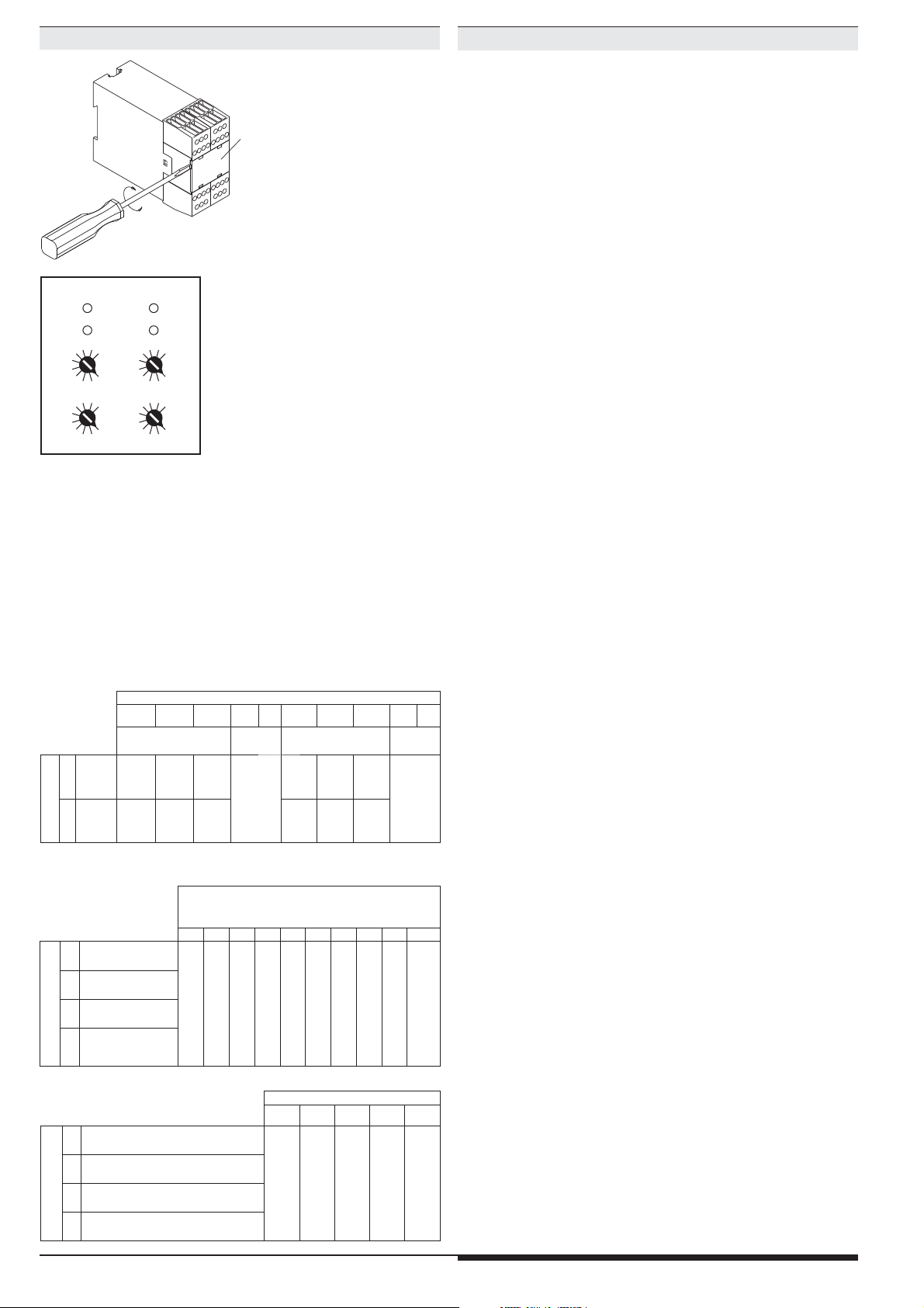
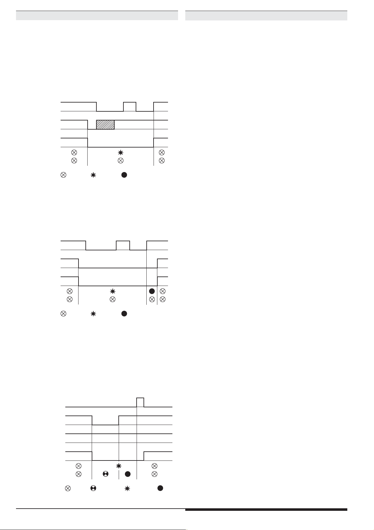
Betriebsart: Schutzbetrieb (Anwendungsbeispiel M7961)
g
g
z. B. Lichtvorhänge zur Absicherung von Gefahrenbereichen
Bis zu 3 BWS anschließbar
Wahlweise Auto- oder Hand-Start für jede BWS einzeln einstellbar
Mit oder ohne Kontaktverstärkung einstellbar
Mögliche Einstellungen:
Funktionsdiagramm
Versorgungsspannung
(A1/A2)
Starttaste (S43/S44)
1
3
Poti 10: Startart und Kontaktverstärkung
0123456789
ohne
Kontaktverstärkun
BWS1
Auto
Auto
Auto
0
BWS2
Hand
Hand
Hand
Hand
Hand
Auto
Hand
Hand
Auto
Hand
BWS3
BWS1
Pot.1
1
BWS2
BWS3
Auto
Auto
Hand
Auto
Auto
nicht zu-
gelassen
(Fehler
5)
mit
Kontaktverstärkun
Auto
Auto
Auto
Hand
Hand
Auto
Hand
M7942
Auto
Auto
Auto
Hand
Auto
Auto
Hand
Hand
Hand
Hand
Hand
nicht zugelassen
(Fehler
5)
Automatischer Start
Beim automatischen Start erfolgt eine sofortige Aktivierung der Maschi-
nenfreigabekontakte K1 und K2, sobald die mit Autostart programmierte
BWS nach einer Lichtwegunterbrechung wieder freigegeben wird.
Voraussetzung ist, dass die mit Handstart programmierten BWS nicht
unterbrochen sind.
Hand-Start
Bei dieser Betriebsart erfolgt die Aktivierung der Maschinenfreigabekon-
takte K1 und K2 erst, wenn die mit Handstart programmierte BWS nach
einer Lichtwegunterbrechung wieder freigegeben und die Start-Taste
betätigt wird.
Die Start-Taste muss bei zwei Zuständen betätigt werden:
- Nach Wiederkehr der Vorsorgungsspannung
(wenn mindestens 1 BWS mit Handstart programmiert ist)
- Wenn eine BWS mit Handstart unterbrochen war
BWS 1 (S12/S14)
mit Autostart
BWS 2 (S22/S24) und/oder
BWS 3 (S32/S34)
mit Handstart
K1, K2
(13-14, 23-24, 33-34)
Warten auf Start (58)
Fehleranzeige (48)
Blinkcode
: dunkel : Dauerlicht : Blinkcode : gleichmäßiges Blinken
2
11
M7967_a
3
Page 4
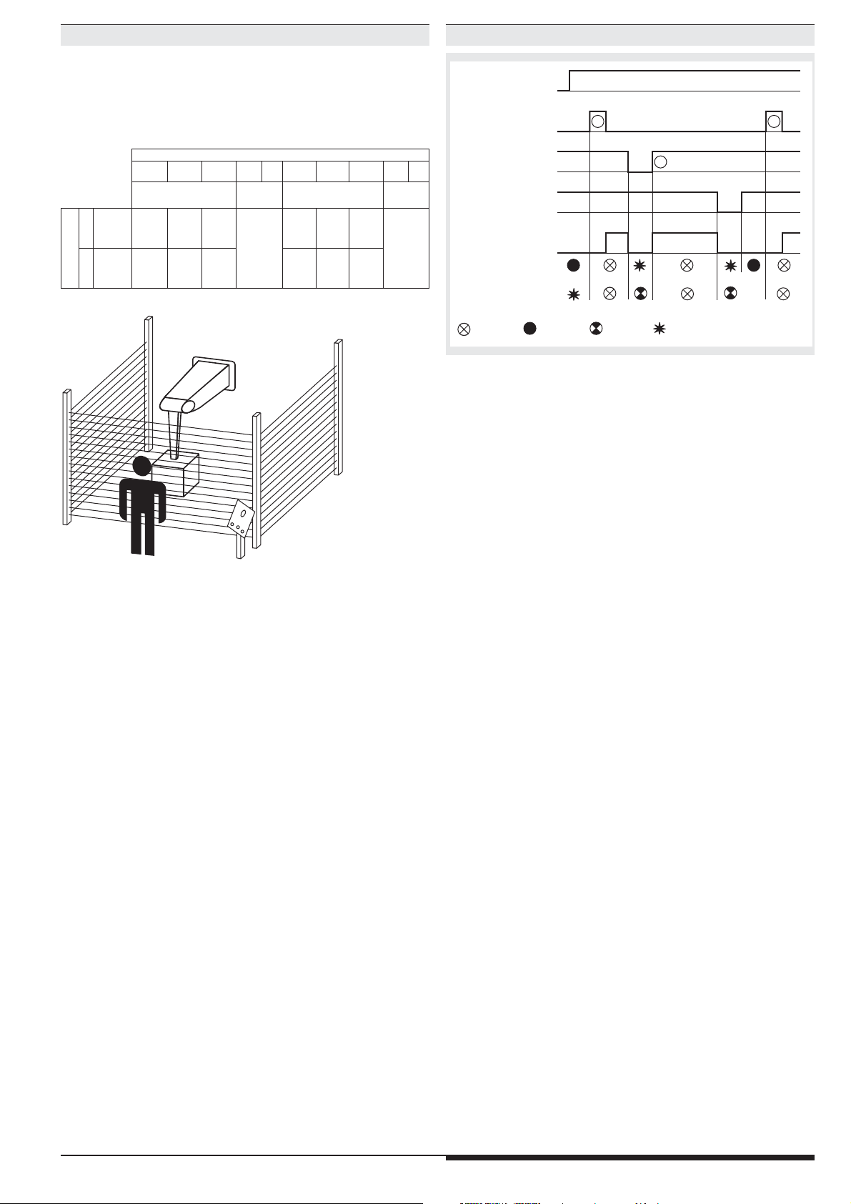
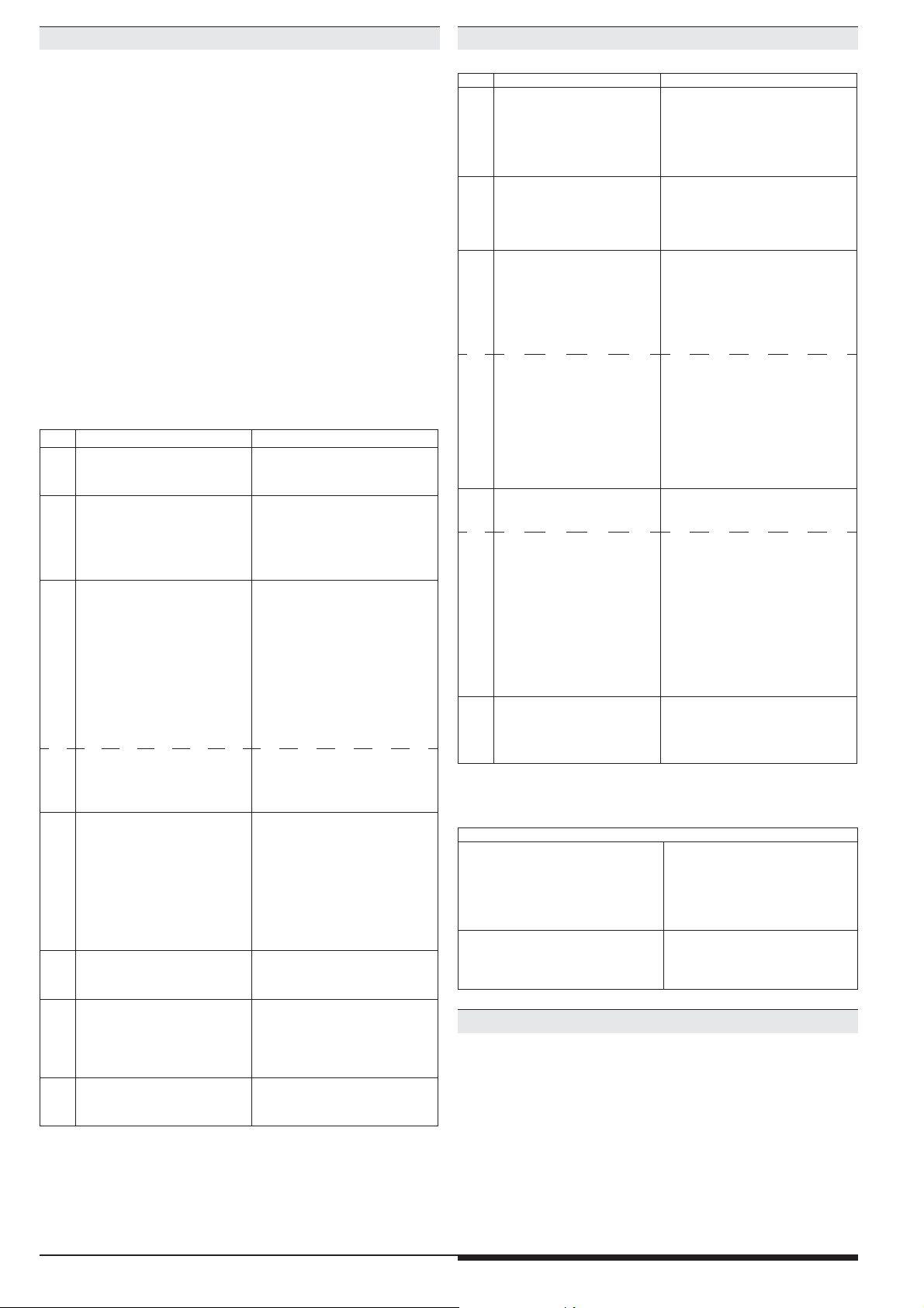
Betriebsart: Schutzbetrieb mit Muting
z. B. Förderband
1 oder 2 BWS
Muting von BWS1
2 oder 4 Muting-Sensoren
Auto- oder Hand-Start
Override über Start-Taster
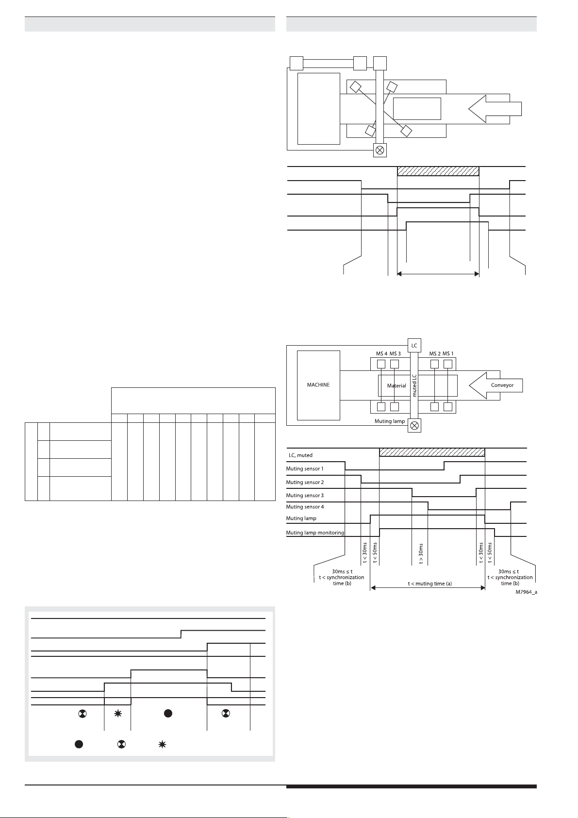
Betriebsart: Schutzbetrieb mit Muting
Verwendung von 2 Muting-Sensoren
BWS
MS1 MS2
Muting (Überbrückung)
Das Muting dient dem vorübergehenden Unwirksamschalten einer BWS.
Diese Funktion wird verwendet, um Fördergut durch eine BWS ungehindert
transportieren zu können. Die Unterscheidung Fördergut oder Mensch wird
durch zusätzliche Muting-Sensoren (MS) realisiert, die eine ganz bestimmte
Signalreihenfolge generieren müssen, wenn Fördergut die BWS passiert.
Die Mutingsteuerung startet dann den Mutingzyklus für die Zeit, in der das
Material durch die BWS transportiert wird. Einer Person darf es nicht möglich
sein, die Mutingsensoren in der gleichen Signalfolge zu aktivieren wie das
Fördergut. Um dies sicher zustellen, können am MSR22LM Betriebsarten mit
2 oder 4 Mutingsignalen eingestellt werden. Damit löst eine Person beim
Zugang in die BWS die Abschaltung der gefahrbringenden Bewegung aus.
Der Mutingvorgang wird mittels einer vom Gerät überwachten Mutingleuchte signalisiert. Die maximal zulässige Dauer des Mutingvorgangs kann in 10
Stufen zwischen 10 s und unendlich eingestellt werden. Ist die BWS1 nach
Ablauf der max. zulässigen Mutingzeit noch unterbrochen, z. B. durch verklemmtes Fördergut, ö nen die Maschinen-Freigabekontakte K1, K2 und die
Mutingleuchte sowie die LED run 1 signalisieren FEHLER-4.
Eine Freigabe durch die Start-Taste ist nur möglich, wenn die Mutingleuchte
in Ordnung und die zu überbrückende BWS frei ist. Während dem
Mutingzyklus führt ein Fehler in der Reihenfolge der Mutingsignale oder ein
Überschreiten der max. zulässigen Mutingzeit zu FEHLER-4. Dieser kann nur
durch Quittieren über den Start-Taster wieder beseitigt werden. Die Mutingsignalquellen sind so anzubringen, dass durch einen Eingri oder Eintritt in
die BWS die richtige Signalfolge nicht erzeugt werden kann (siehe hierzu die
Angaben in IEC/EN 61496-1).
Mögliche Einstellungen:
Maschine
gemutete BWS
Mutingleuchte
BWS, gemutet
Muting-Sensor MS1
Muting-Sensor MS2
Mutingleuchte
Mutingleuchtenkontrolle
2
1
t < 50ms
t < 30ms
30ms t
£ 30ms t
t < Synchronzeit (b)
Verwendung von 4 Muting-Sensoren
Fördergut
t < Mutingdauer (a)
Förderband
2
1
t < 50ms
t < 30ms
t < Synchronzeit (b)
£
M7970_a
Poti 10:
a = max. Mutingzeit
b = max. Synchronisationszeit
012345678 9
BWS1 Auto-Start,
2
Muting 2 Signale
BWS1 Hand-Start,
3
Muting 2 Signale
BWS1 Auto-Start,
Pot.1
4
Muting 4 Signale
BWS1 Hand-Start
5
Muting 4 Signale
,
a: 20 s / b: 3 s
a: 10 s / b: 3 s
a: 30 s / b: 3 s
a: 1 min / b: 6 s
a: 5 min / b: 30 s
a: 15 min / b: 90 s
a: 1 h / b: 3 min
a: 30 min / b: 3 min
a: 8 h / b: 3 min
Override
Ist der Überwachungsbereich bei abgefallenen Sicherheitsrelais durch ein
Fördergut blockiert, wird dies beim Betätigen der Start-Taste durch ein
schnelles Blinken (ca. 3 Hz) der Mutingleuchte signalisiert. Der Bediener
kann die Sicherheitsrelais durch ein längeres Betätigen des Start-Tasters
nach 3 Sekunden für maximal 12 Sekunden freigeben, bis die Mutingsensoren wieder inaktiv werden oder die Start-Taste nicht mehr gedrückt wird.
Beispiel eines Override-Zyklus bei Muting mit 2 Sensoren
ungemutete BWS2
gemutete BWS1
Muting-Sensor MS1
Muting-Sensor MS2
Sicherheitsrelais K1/K2
Starttaster
Mutingleuchte
keine Muting
Zeitüberwachungen
Fehlercode
12
t=3 S
: Dauerlicht : Blinkcode : schnelles Blinken (3Hz)
override
t<12S
M9476
4
Page 5
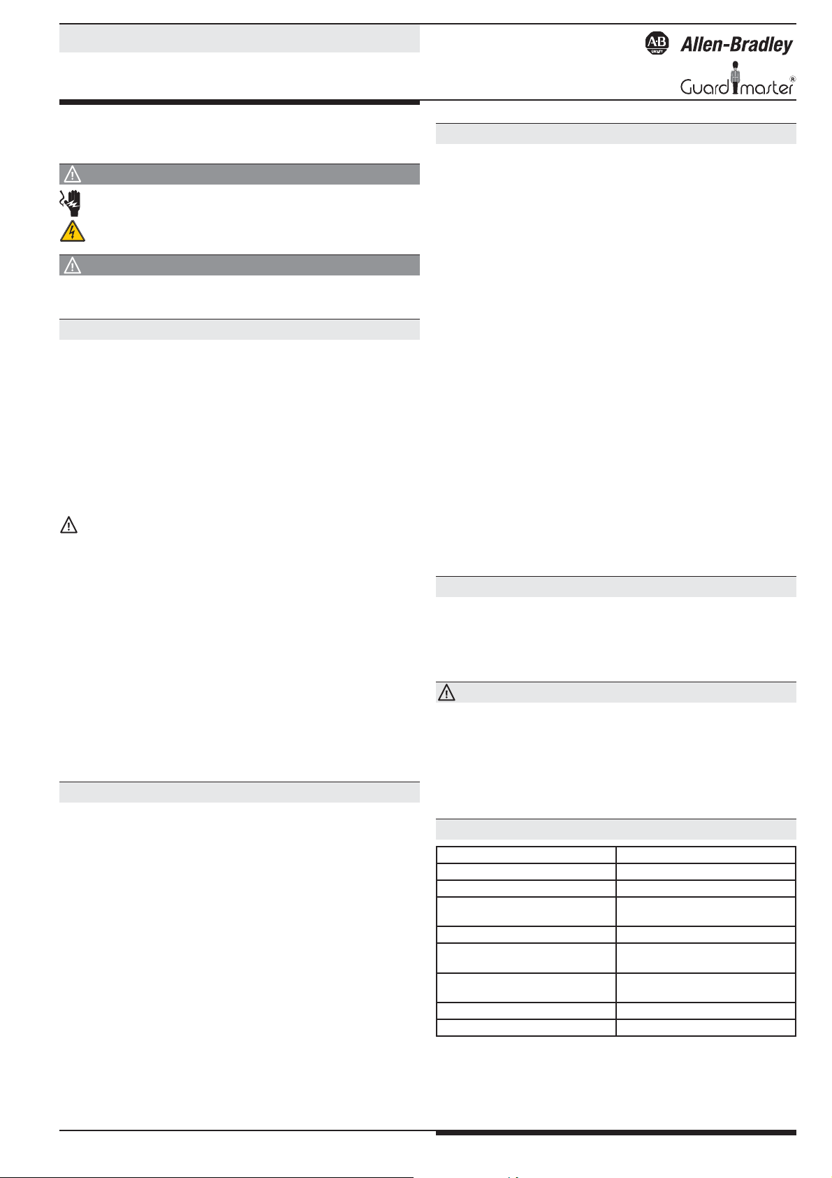
Betriebsart: Taktbetrieb
z. B. Pressen mit manuellem Eingri und automatischem Start
Max. 3 BWS
Einstellbare Funktionen:
1, 2 oder 3 Takte
Taktzahl über Poti 1 oder über Schlüsselschalter umschaltbar
2 verschiedene Startsequenzen
2 Abfragearten des Maschinenkontaktes
Der Taktbetrieb ermöglicht einen automatischen Wiederanlauf einer Maschine (Presse) nach einer de nierten Anzahl von Eingri en in das Schutzfeld
der ersten BWS. Diese Betriebsart besteht aus einer Startsequenz und dem
Normalablauf.
Mögliche Einstellungen:
Taktbetrieb
Kontakt-Abfrageart 1,
6
Start-Sequenz: Takte und Start
Kontakt-Abfrageart 2,
7
Start-Sequenz: Takte und Start
Kontakt-Abfrageart 1
Poti 1
8
Start-Sequenz: Start und Takte
Kontakt-Abfrageart 2
9
Start-Sequenz: Start und Takte
Poti 10: Anzahl Takte
0 1 2 3 4 - 9
1 Takt
2 Takte
3 Takte
Schlüsselschalter
umschaltbar über
nicht zugelassen
Startsequenz
Um die Maschine bei Taktbetrieb nach dem Einschalten frei zu geben, können zwei mögliche Startsequenzen gewählt werden:
1.) Es müssen zuerst die geforderten Eingri e getätigt und dann die
Start-Taste gedrückt werden.
2.) Zuerst ist die Start-Taste zu betätigen. Danach müssen die geforderten
Eingri e erfolgen.
Die Au orderung, die Eingri e zu tätigen, (z. B. 2 Takte gemäß untenstehenden Diagrammen) wird durch Blinken der Leuchte (Klemme 48) angezeigt.
Die Au orderung, die Start-Taste zu betätigen, erfolgt durch Dauerlicht der
Leuchte an Klemme 58. Nach korrektem Ablauf der Startsequenz erlöschen
die Leuchten und die Maschinen-Freigabekontakte K1, K2 schließen.
Versorgungsspannung
(A1/A2)
Starttaste(S43/S44)
BWS 1 (S12/S14)
BWS 2 (S22/S24) und/oder
BWS 3 (S32/S34)
K1, K2
(13-14, 23-24, 33-34)
Warten auf Eingriff (48)
Warten auf Start (58)
: dunkel
: blinken 1Hz
: blinken 3Hz
Start-Sequenz: 2 Takte und Start-Taste
Versorgungsspannung
(A1/A2)
Starttaste(S43/S44)
BWS 1 (S12/S14)
(Fehler 5)
BWS 2 (S22/S24) und/oder
BWS 3 (S32/S34)
: hell
M7976_a
K1, K2
(13-14, 23-24, 33-34)
Warten auf Eingriff (48)
Warten auf Start (58)
: dunkel
: blinken 1Hz
: blinken 3Hz
: hell
M7977_a
Start-Sequenz: Start-Taste und 2 Takte
Eine korrekt abgelaufene Startsequenz ist Bedingung für den folgenden
Normalablauf. Bei diesem wird der Hub der Maschine dem Lichtgittermodul
durch das Ö nen und Schließen eines Maschinenkontaktes mitgeteilt. Die
Ausgangskontakte des Lichtgittermoduls werden mit dem Ö nen des Maschinenkontaktes inaktiv. Danach muss der Bediener bewußt die geforderte
Anzahl von Eingri en (Takten) in die BWS tätigen, um die Maschine automatisch wieder in Gang zu setzen. Alle geforderten Takte müssen innerhalb von
30 s erfolgen.
Die Au orderung, die Eingri e zu tätigen, wird durch Blinken (ca. 3 Hz) der
Leuchte (Klemme 48) angezeigt. Wenn alle geforderten Eingri e erfolgt
sind, erlischt die Leuchte und die Maschinen-Freigabekontakte K1, K2
schließen.
5
Page 6
Betriebsart: Taktbetrieb
Betriebsart: Taktbetrieb mit Schlüsselschalter
Maschinenkontakt
An das Gerät muss über die Klemmen S41 - S42 ein Maschinenkontakt
angeschlossen werden. Er ö net und schließt in Abhängigkeit des Hubs der
Presse.
Abfragearten des Maschinenkontaktes
Es sind zwei Abfragearten des Maschinenkontaktes wählbar:
Abfrageart 1
Bei dieser Abfrageart dürfen die Eingri e in die BWS erst erfolgen, wenn der
Maschinenkontakt geö net und wieder geschlossen wurde. Eine Ausnahme
ist, wenn der Eingri bei geö netem Kontakt erfolgt und noch andauert,
wenn der Kontakt wieder geschlossen ist.
BWS 1 (S12/S14)
Maschinenkontakt
(S41/S42)
K1, K2
(13-14, 23-24, 33-34)
Warten auf Eingriff (48)
Warten auf Start (58)
: blinken 3Hz
: hell: dunkel
M7978_b
Anwendung: Pressen mit durchschnittlicher bis schneller Hub geschwindigkeit
Abfrageart 2
Bei dieser Abfrageart werden die Eingri e bereits bei o enem Maschinenkontakt erkannt. Die Maschine wird aber erst wieder freigegeben, wenn
sowohl alle Eingri e getätigt sind, als auch der Maschinenkontakt wieder
geschlossen ist.
z. B. Pressen mit wechselnder Taktzahl
• Umschaltmöglichkeit mittels Schlüsselschalter: 1, 2 oder 3 Takte
Umschalterkennung
Die Umschaltung wird nur bei Maschinenstillstand (K1, K2 o en) erkannt. Die
Erkennung der neuen Schlüsselschalterstellung wird durch die Anzeige des
Fehlercodes 3 an der Leuchte der Klemme 48 signalisiert. Mittels Freigabe
durch Start-Tasten-Betätigung erfolgt zuerst ein Neu-Start des Gerätes. Die
bereits eingestellte Start-Sequenz mit der geänderten Taktzahl muss nach
dieser ersten Start-Tasten-Betätigung komplett (Takte und Start-Taste bzw.
Start-Taste und Takte) durchlaufen werden, um die Maschine mit der neuen
Taktzahl frei zu geben.
BWS 1 (S12/S14)
Maschinenkontakt
(S41/S42)
K1, K2
(13-14, 23-24, 33-34)
Warten auf Eingriff (48)
Warten auf Start (58)
: blinken 3Hz
: hell: dunkel
M7979_c
Anwendung: Pressen mit langsamer Hubgeschwindigkeit
Unerlaubter Eingri in BWS
Unerlaubte Eingri e in die BWS führen zum Abschalten der Maschinen-Freigabekontakte K1, K2. Bei unerlaubten Eingri en blinkt die Leuchte (Klemme
58) regelmäßig. Die Leuchte an Klemme 48 blinkt mit dem Fehlercode 1.
Nach Beendigung des Eingri s geht die Leuchte an Klemme 58 in Dauerlicht
über und signalisiert, dass der Maschinenstart durch Betätigung der StartTaste erfolgen kann.
Starttaste(S43/S44)
BWS 1 (S12/S14),BWS 2
(S22/S24) o. BWS 3 (S32/S34)
Maschinenkontakt
(S41/S42)
K1, K2
(13-14, 23-24, 33-34)
Warten auf Eingriff (48)
Warten auf Start (58)
: dunkel
: blinken 1Hz
: Fehlercode
: hell
M7980_b
6
Page 7

Technische Daten
Eingang
Nennspannung UN: DC 24 V
Spannungsbereich:
bei max. 5 % Restwelligkeit: 0,85 ... 1,15 U
Nennverbrauch: max. 170 mA
N
(Halbleiterausgänge unbelastet)
Steuerspannung über
S21, S23, S31, S33, S41, S43,
48, 58: DC 23 V bei U
Steuerstrom über
N
S12, S14, S22, S24,
S32, S34, S42, S44: je 4,5 mA bei U
Mindestspannung an
N
Klemmen S12, S14, S22,
S24, S32, S34 S42, S44: DC 16 V
Absicherung des Gerätes: Intern mit PTC
Mindeststrom an M1, M2: 25 mA bei eingeschalteter Lampe
Ausgang
Kontaktbestückung
MSR22LM.03: 3 Schließer
MSR22LM.22: 2 Schließer, 1 Ö ner
Der Ö ner darf nur als Meldekontakt
verwendet werden!
Kontaktart: Relais, zwangsgeführt
Einschaltzeit typ. bei UN:
Handstart: max. 50 ms
Automatischer Anlauf: max. 1,5 s
Automatischer Wiederanlauf: max. 55 ms
Abschaltzeit (Reaktionszeit): max. 30 ms
(max. 50 ms, wenn Fehler an BWS
und nur 1 Eingangskanal der BWS
abschaltet)
Ausgangsnennspannung: max. AC 250 V
DC: siehe Lichtbogengrenzkurve*
)
*) siehe Datenblatt MSR22LM unter www.rockwellautomation.com
Schalten von Kleinlasten: 100 mV
Thermischer Strom Ith: 5 A
Schaltvermögen
nach AC 15
Schließer: 3 A / AC 230 V IEC/EN 60 947-5-1
Ö ner: 2 A / AC 230 V IEC/EN 60 947-5-1
nach DC 13 bei 0,1 Hz: 8 A / DC 24 V IEC/EN 60 947-5-1
Elektrische Lebensdauer
nach AC 15 bei 2 A, AC 230 V: 105 Schaltspiele IEC/EN 60 947-5-1
Zulässige Schalthäu gkeit: max. 1 200 Schaltspiele / h
Kurzschlußfestigkeit
max. Schmelzsicherung: 6 A gL IEC/EN 60 947-5-1
Sicherungsautomat: C 8 A
Mechanische Lebensdauer: 10 x 106 Schaltspiele
Technische Daten
Stoßspannung (Surge)
zwischen
Versorgungsleitungen: 1 kV IEC/EN 61 000-4-5
zwischen Leitung und Erde: 2 kV IEC/EN 61 000-4-5
HF-leitungsgeführt: 10 V IEC/EN 61 000-4-6
Funkentstörung: Grenzwert Klasse B EN 55 011
Schutzart: nach IEC/EN 61 496-1 muss das Gerät in ein
Steuergehäuse mit Schutzklasse 54 unter
gebracht werden
Gehäuse: IP 40 IEC/EN 60 529
Klemmen: IP 20 IEC/EN 60 529
Gehäuse: Thermoplast mit V0-Verhalten
nach UL Subject 94
Rüttelfestigkeit: nach IEC/EN 61 496-1
Amplitude 0,35 mm
Frequenz 10 ... 55 Hz, IEC/EN 60 068-2-6
Schockfestigkeit:
Beschleunigung: 10 g
Impulsdauer: 16 ms
Anzahl der Schocks: 1000 je Achse auf drei Achsen
Klimafestigkeit: 0 / 050 / 04 IEC/EN 60 068-1
Klemmenbezeichnung: EN 50 005
Leiterbefestigung: unverlierbare Plus-Minus-Klemmen-
schrauben M3,5 Kastenklemmen mit
selbstabhebendem Drahtschutz
Schnellbefestigung: Hutschiene IEC/EN 60 715
Nettogewicht: 320 g
UL-Daten
Die Sicherheitsfunktionen des Gerätes wurden nicht durch die UL
untersucht. Die Zulassung bezieht sich auf die Forderungen des Standards UL508, “general use applications“.
Nennspannung UN: DC 24 V
Umgebungstemperatur: 0 … +50°C
Schaltvermögen:
Umgebungstemperatur 50°C: Pilot duty B300
5A 250Vac G.P.
5A 24Vdc
Halbleiterausgänge: 24Vdc, 100 mA
Leiteranschluß: nur für 60°C / 75°C Kupferleiter
AWG 20 - 12 Sol Torque 0.8 Nm
AWG 20 - 14 Sol Torque 0.8 Nm
Fehlende technische Daten, die hier nicht explizit angegeben
werden, sind aus den allgemein gültigen technischen Daten zu
nfo
entnehmen.
Halbleiterausgänge
Ausgang (Klemme 48 und 58): Transistorausgänge, plus-schaltend
Ausgangsnennspannung: DC 24 V, max. 100 mA Dauerstrom,
max. 400 mA für 0,5 s interner Kurz schluss-, Übertemperatur und Überlast schutz
Allgemeine Daten
Nennbetriebsart: Dauerbetrieb
Temperaturbereich:
Betrieb: ± 0 ... + 5˚ C
Lagerung : - 25 ... + 85˚ C
Betriebshöhe: < 2.000 m
Luft- und Kriechstrecken
Bemessungsstoßspannung /
Verschmutzungsgrad: 4 kV / 2 (Basisisolierung) IEC 60 664-1
EMV
Statische Entladung (ESD): 8 kV (Kontaktentlad.) IEC/EN 61 000-4-2
(entsprechend Prüfschärfegrad 3)
HF-Einstrahlung: 10 V / m IEC/EN 61 000-4-3
Schnelle Transienten:
auf Versorgungsleitung A1-A2: 2 kV IEC/EN 61 000-4-4
auf Signal und Steuerleitungen: 2 kV IEC/EN 61 000-4-4
7
Page 8
Vorgehen bei Störungen
Bei Erkennen eines Fehlers fallen immer die Relais K1 / K2 ab.
Die unterschiedlichen Fehler werden durch verschiedene Blinkfolgen an
den LEDs run 1 und run 2 angezeigt.
Die Unterscheidung der Fehler erfolgt in 2 Gruppen.
Fehlerg ruppe 1:
Systemfehler
Nach Erkennen eines solchen Fehlers verriegelt sich das Modul und zeigt nur
noch den Fehlercode an. Das Modul kann nur durch Aus- und Wiedereinschalten des Moduls zurückgesetzt werden. Diese Fehler werden nur an den
LEDs run 1 und / oder run 2 angezeigt. Es können zur gleichen Zeit verschiedene Fehlercodes an beiden LEDs angezeigt werden. Die Ausgänge 48 und
58 sind in diesem Zustand immer dauernd ausgeschaltet.
Fehlerg ruppe 2:
Funktionsfehler
Diese Fehler werden immer an der LED run 1 und am Ausgang 48 angezeigt,
während die LED run 2 im Dauerlicht bleibt. Die Relais K1 / K2 sind in diesem
Zustand inaktiv. Das Modul ist aber noch voll funktionsfähig und die Relais
können wieder aktiviert werden, wenn der Fehler behoben ist, und die
Starttaste betätigt wird.
Systemfehler: (nur an LEDs run 1 und/oder run 2 angezeigt)
)
Nr.*
Beschreibung Maßnahmen und Hinweise
Interner Gerätefehler (beide
0
LEDs sind konstant aus)
Wenn beide LEDs aus bleiben,
ist das Gerät defekt und muss zur
Reparatur
1) Die Drehschalterstellungen
der beiden Kanäle stimmen
5 Einstellfehler
nicht überein.
2) Die gewählte Einstellung ist
nicht zulässig.
Linke LED blinkt.
Die Versorgungsspannung ist
unter die zulässige Spannung
). Nach
N
6 Unterspannungserkennung
gesunken (< ca. 0,85 U
jedem Anzeigenzyklus des Fehlercodes wird die Spannung neu
gemessen. Ist sie wieder im zulässigen Bereich, wird ein Reset
(wie beim Einschalten der
Versorgungsspannung) des Moduls
durchgeführt.
Rechte LED blinkt:
6 Überspannungserkennung
Die Versorgungsspannung ist
zu hoch
(> ca. 1,15 U
+ 5 % Restwelligkeit).
N
1) Es ist ein Kurzschluss an
den Eingängen der Start Taste oder des Maschinen kontaktes (Schutzbetrieb)
7 Eingangsfehler
aufgetreten
2) Die zwei Signale einer CDS
stimmen nicht überein
(Kurzschluss, Leitungsbruch
oder defekte CDS)
Fehler an den Maschinen-
8
freigaberelais K1, K2
9
Schaltung und Schaltströme
überprüfen. Das Gerät
muss zur Reparatur.
Versuchen Sie den Ablauf festzustellen, der zu dieser Fehler-
1011Interne Gerätefehler
meldung führt und teilen Sie
diesen Ablauf dem Hersteller
oder Verkäufer des Gerätes mit.
12
Interne Gerätefehler Das Gerät muss zur Reparatur.
13
*) Nr.: Anzahl der aufeinanderfolgenden Blinkimpulse
Vorgehen bei Störungen
Funktionsfehler: Anzeige an run 1 und Ausgang 48
)
Nr.*
Beschreibung Maßnahmen und Hinweise
1)
Eine BWS wurde unterbrochen.
2) Anstelle unbenutzter BWS
1 BWS Fehler
müssen Brücken vorhanden
sein:
BWS 2: S21-S22, S23-S24
BWS 3: S31-S32, S33-S34
1) Der Starttaster darf nicht
beim Einschalten des Moduls
2 Fehler am Starttaster
betätigt sein.
2) Der Start-Taster darf nicht länger
als 3 s betätigt sein.
1) Es ist eine Betriebsart mit
Kontaktverstärkung eingestellt
Reiner Schutzbetrieb:
3
FSD-Fehler
und der überwachte Kontakt,
an S41- S42 angeschlossen
der
wer
den muss, ist vor dem
Aktivieren der Relais K1, K2
nicht geschlossen.
1) Der Maschinenkontakt ist
im Ruhezustand des Sicher heitsmoduls (Warten auf
3
Taktbetrieb
Kontaktfehler
die Startbedingung) nicht
angeschlossen.
2) Bei Kontaktart 1 war der
Maschinenkontakt am Ende
des geforderten 1. Eingri s
in die BWS noch o en.
4
Muting-Fehler
(Blockierung)
1) Die eingestellte max. Muting dauer wurde überschritten
(Mutinglampe an).
2) Die Mutinglampe ist nicht
zwischen der Klemme 48 und
den Klemmen M1 und M2 an geschlossen.
4
Muting-Fehler
(Lampe)
3) Die erforderliche Brücke an
den Klemmen S41 und S42
ist nicht angeschlossen.
4) Die Mutinglampe ist defekt.
5) Die Messschaltung für die
Mutinglampe ist defekt.
Das Gerät muss zur Reparatur.
1) Beide Kontakte des
Taktbetrieb
5
(Schlüsselfehler)
Schlüsselschalters für die
Einstellung der Taktzahl sind
o en.
*) Nr.: Anzahl der aufeinanderfolgenden Blinkimpulse
Zustandsanzeigen
run 1 und Ausgang 48 blinken schnell mit ca. 3 Hz
Mindestens ein Mutingsensor ist
aktiv, BWS 1 ist unterbrochen und
Muting-Betrieb:
Override möglich
der Starttaster wird betätigt. Nach
3 s ununterbrochener Betätigung
des Starttasters wird das Override
für max. 12 s eingeleitet.
Es wird auf die vorgegebene AnTaktbetrieb:
Warten auf Eingri e
zahl der Eingri e in die BWS ge-
wartet, um die Sicherheitsrelais
wieder aktivieren zu können.
Wartung und Instandsetzung
- Das Gerät enthält keine Teile, die einer Wartung bedürfen.
- Bei vorliegenden Fehlern das Gerät nicht ö nen, sondern an den
Hersteller zur Reparatur schicken.
8
Page 9
Operating instructions ENGLISH
Light curtain controller MSR22LM
with selectable operating modes
Printed in G ermany, Dwg. No: 23992, EO: 0329, Is sue No: 3
ORIGINAL
Before installing, operating or maintaining this device, these instructions
must be carefully read and understood.
DANGER
Dangerous voltage.
Electric shock will result in death or serious injury.
Disconnect all power supplies before servicing equipment.
CAUTION
Safe operation of the device is only guaranteed when using certi ed
components!
Important Notes
The product hereby described was developed to perform safety functions as
a part of a whole installation or machine. A complete safety system normally
includes sensors, evaluation units, signals and logical modules for safe
disconnections. The manufacturer of the installation or machine is
responsible for ensuring proper functioning of the whole system. Rockwell
Automation cannot guarantee all the speci cations of an installation or
machine that was not designed by Rockwell Automation. The total concept
of the control system into which the device is integrated must be validated
by the user. Rockwell Automation also takes over no liability for
recommendations which are given or implied in the following description.
The following description implies no modi cation of the general Rockwell
Automation terms of delivery, warranty or liability claims.
Safety Regulations
- This device must be installed and operated by sta who are familiar with
these instructions and with the current regulations for safety at work
and accident prevention.
- Pay attention to applicable local regulations, especially regarding safety
measures.
- The shock protection on the connected elements and the cable
insulation must be designed for the highest voltage applied to the
device.
- Opening the device or implementing unauthorized changes voids any
warranty.
- The unit should be panel mounted in an enclosure rated at IP 54 or
superior. Dust and dampness may lead to malfunction.
- Adequate fuse protection must be provided on all output contacts with
capacitive and inductive loads.
- The safety function must be triggered at least once a month.
Designated use
The MSR22LM interrupts a safety circuit in a safe way. In applications with
light curtains it can be operated in protection, muting and stepping mode
to protect people and machinery.
When used in accordance with its intended purpose and following these
operating instructions, this device presents no known residual risks.
Nonobservance may lead to personal injuries and damages to property.
Main features
According to
- Performance Level (PL) e and category 4 to EN ISO 13849-1: 2008
- SIL Claimed Level (SIL CL) 3 to IEC/EN 62061
- Safety Integrity Level (SIL 3) to IEC/EN 61508
- Category 4 to EN 954-1
To connect max.:
- 3 light curtains 2-channel or
- 2 light curtains 2-channel and 2 muting sensors 1-channel or
- 1 light curtain 2-channel and 4 muting sensors 1-channel or
- 2 light curtains 2-channel and key switch for stepping operation
- Additionally: Start button and machine contact with line fault detection
Broken wire detection on light curtain input
Outputs:
- 3 N/O or 2 N/O and 1 N/C
- 2 Semiconductor outputs, protected against short circuit and overload
Multifunction device, di erent functions selectable by rotational
switches:
- Protective operation e.g. light curtains
- Protective operation with muting, e.g. conveyors
- Signal sequence of muting sensors can be selected
- Override function via start button
- Stepping operation e.g. on presses
- Optionally with key switch
- 1, 2 or 3 steps possible
- Setting of number of step possible via selector switch
Suitable to connect light curtains of type 4 or selftesting light curtains
type 2 according to IEC/EN 61 496-1, crossfault monitoring in the light
curtain
With under- and overvoltage detection and indication
Reaction time: max. 30 ms
LED indication for RUN and Channel 1, 2
Practical notes
Before removing the front plate the person must be discharged to
ground.
The muting lamp must be conform to IEC/EN 61 496-1 section A7.4
If an input is not used, 2 wire links have to be made according to picture 9
on the terminals S-1/S-2 and S-4/S-3.
Safety notes
ATTENTION!
On MSR 22LM the NC contact 31-32 must only be used as moni toring contact.
Not suitable for machines where the area behind the light curtain is
accessable
Settings have to be carried out by educated personnel with disconnected
Connection Terminals
Terminal designation Signal designation
A1+ + / L
A2 - / N
S12, S14, S22, S24, S32, S34,
S42, S44, M1, M2
S21, S23, S31, S33, S33, S41, S43 Outputs
13, 14, 23, 24, 33, 34
31,32
48, 58 Semiconductor monitoring output
X44 Free junction terminal, volt free
Inputs
Positive driven N/O contacts for
release circuit
Positive driven N/C contacts for
release circuit
All infor mation mention ed in this technic al speci ca tion is according to this publicatio n.
We reser ve the right to techni cal changes and mo di cations.
9
Page 10
Setting
03
69
03
690369
03
69
ch1 ch2
10
1
M8015
Ansicht innen
Example:
Required function:
Protective operation with
manual start, with muting,
4 muting sensors, max. 30 s
plate
M2929
muting time.
Setting:
Upper switches set to "5" for
both processors
Lower switches set to "2" for
both processors
The function setting of MSR22LM is made by 4 rotational switches behind
the frontplate (see picture). The switches on the left make the setting for
μprocessor 1 (LED run 1) and the switches on the right for μprocessor (LED
run 2). For both processors the same functions must be set. On the upper
switches (1) the main function is adjusted. On the lower switches (10) the
setting of the muting time (Protective operation) or the number of steps
(stepping operation) is adjustable.
On muting or stepping function the light curtains LC 2 and LC 3 are always in
protective operation with manual start.
Protective operation without muting
Indicators
Lower gree n LEDs
K1, K2: - On, when K1 and K2 are energized
Upper yel low LED
run 1: - Permanent on, when relay K1 and K2 are
energized
- F
lashes with 1 Hz when the unit waits for
the
start signal after fault free operation (power up
of the unit)
- Flashes fast with approx. 3 Hz when the start
button is pressed and all conditions for an
override are ful lled during muting
- Flashes fast with approx. 3 Hz when at stepping
operation the unit waits for interruption of the
light curtain
- Flashes with failure code to indicate normal
indication states that disable the energisation
of the output relays (e.g. after not allowed
interruption of the light curtain) until the start
button is pressed
- Flashes with failure code to indicate
special failures (e.g. undervoltage)
Semico nductor out put 48:
- O , when unit is on special failure mode
- Normally o when relays K1 and K2 are
energized
- Continuously on, when unit in muting mode
- Shows the same failure codes as LED
run 1 (except on special failures)
Upper yel low LED run 2: - Permanent on, when unit operates correctly
- Flashes with failure code to indicate special
operation failures (e.g. undervoltage)
Semico nductor outp ut 58: - O , when unit is on special failure mode
- O , when relays K1 and K2 are energized
- Symmetric ashing, when a normal functional
state is active that disables the energisation of
the output relays (e.g. not allowed interruption
of a light curtain)
- Permanent on, when waiting for start
Switch 10: Start mode and feedback input
0123456789
without feedback
Auto
Manu
Manu
Manu
Manu
Manu
input
Auto
Auto
Manu
Manu
Auto
Manu
Switch 1
0 LC 1
LC 2
LC 3
1 LC 1
LC 2
LC 3
Protective operation with muting
2 LC S1 Auto,
muting 2 sensors
3 LC S1 Manu,
muting 2 sensors
4 LC S1 Auto,
muting 4 sensors
Switch 1
5 LC S1 Manu,
Muting 4 sensors
Stepping operation
Stepping operation, contact type 1,
6
Start-sequence: stepping and start
Stepping operation, contact type 2,
7
Start-sequence: stepping and start
Stepping operation, contact type 1,
8
Switch 1
Start-sequence: start and stepping
Stepping operation, contact type 2,
9
Start-sequence: start and stepping
012 3 4 5 6 7 8 9
a: 10 s / b: 3 s
with feedback input
Auto
Auto
Auto
Manu
Auto
Auto
b = maximum synchronising time
a: 20 s / b: 3 s
a: 30 s / b: 3 s
Auto
Manu
not
Manu
allowed
Manu
(fault 5)
Manu
Manu
Switch 10:
a = maximum muting time
a: 1 min / b: 6 s
a: 5 min / b: 30 s
Switch 10: Number of steps
01234 - 9
switch
selectable by key
Auto
Auto
Auto
Auto
Manu
Auto
Manu
Manu
Auto
Auto
Manu
Auto
a: 15 min / b: 90 s
a: 1 h / b: 3 min
a: 30 min / b: 3 min
1 step
2 step
not
allowed
(fault 5)
a: 8 h / b: 3 min
no muting time monitoring
3 step
not allowed (fault 5)
10
Page 11

Operation mode: Protective operation (see M7961)
e.g. light curtains to secure dangerous areas
Connection up to 3 light curtains
Manual or automatic start possible for each light curtain
With or without feedback input for external contactors
Possible settings:
Switch 10: Start mode and feedback input
0123456789
Switch 1
0 LC 1
LC 2
LC 3
1 LC 1
LC 2
LC 3
without feedback
input
Auto
Auto
Manu
Auto
Manu
Manu
Manu
Manu
Manu
Auto
Manu
Manu
Auto
Auto
Auto
Manu
Auto
Auto
allowed
(fault 5)
not
Auto
Manu
Manu
Manu
Manu
Manu
with feedback input
Auto
Auto
Manu
Manu
Auto
Manu
Auto
Auto
Auto
Manu
Auto
Auto
Function diagram
not
allowed
(fault 5)
M7942
Automatic start
On automatic start the contacts K1 and K2 are energized when the light
curtain that is set for auto start is free after interruption. It is necessary that
the other light curtains with manual start are not interruped.
Manual start
On manual star t the contacts K1 and K2 are en ergized when the light barrie r
that is set for manual start is free after interruption and the start button is
pressed.
The start button must be activated in 2 conditions:
- After return of the supply voltage
(when minimum 1 light curtain is programmed for manual start)
- When 1 light curtain with manual start was interrupted
11
Page 12

Operation mode: Protective operation with muting
e.g. conveyors
1 or 2 light curtains
Muting of light curtain 1
2 or 4 muting sensors with di erent input sequences
Auto or manual start
Override via start button
Muting
Muting means to disable temporarily the protective function of a light
curtain. This function is used to transport material through a light curtain
without stopping the machine. The di erentiation between material and
persons is done by additional muting sensors which have to create a certain
switching sequence together with the light curtain when material passes
the light curtain. The muting control starts then the muting cycle for the
time the material is passing the light curtain. It must not be possible that
a person activates the muting sensors in the same switching sequence as
the material. To realise this function 2 di erent switching sequences can be
chosen on MSR22LM either with 2 or 4 muting sensors. This makes sure that
if a person passes the light curtain the dangerous movement of the machine
is stopped immediately. The muting cycle is indicated by a muting lamp that
is controlled and monitored by the MSR22LM. The maximum muting time
can be set in 10 steps between 10 s and in nite.
If the light curtain is still interrupted after the max. permitted muting time
e.g. by blocked material the contacts K1, K2 open and the muting lamp as
well as the LED run 1 show failure code 4.
Starting by pressing the start button is only possible if the muting lamp is
working and the light curtain to be muted is free of interruption. During
the muting cycle a wrong switching sequence or exceeding the maximum
muting time leads to failure code 4. This failure can only be reset by pressing
the start button. The muting sensors have to be installed in a way, that
the correct sequence cannot be achieved manually or by passing the light
curtain (see IEC/EN 61 491-1).
Possible settings
Operation mode: Protective operation with muting
Using 2 muting sensors
Using 4 muting sensors
Switch 10:
a = maximum muting time
b = maximum synchronising time
012 3 4 5 6 7 8 9
2 LC S1 Auto,
muting 2 sensors
3 LC S1 Manu,
muting 2 sensors
4 LC S1 Auto,
Switch 1
muting 4 sensors
5 LC S1 Manu,
Muting 4 sensors
a: 20 s / b: 3 s
a: 10 s / b: 3 s
a: 30 s / b: 3 s
a: 1 min / b: 6 s
a: 5 min / b: 30 s
a: 15 min / b: 90 s
a: 1 h / b: 3 min
a: 30 min / b: 3 min
a: 8 h / b: 3 min
Override
If the monitored area is blocked by transported material and the outputs
K1, K2 are switched o , this is indicated by fast ashing (approx. 3 Hz) of the
muting lamp. The operator can activate the outputs K1, K2 by pressing the
start button for more than 3 s for a maximum time of 12 s until the muting
sensor are again inactive or the start button is released again.
Example for an override cycle when muting with 2 sensors
unmuted LC2
muted LC1
muting sensor 1
muting sensor 2
safety relay K1/K2
start button
muting lamp
no muting time monitoring
error code
12
t=3 S
: on : flashing : fast flashing (3Hz)
override
t<12S
M9477
12
Page 13

Operation mode: Stepping operation
e.g. Presses with manual operation and automatic start
Max. 3 light curtains
Setting functions:
1, 2 or 3 steps
2 di erent start sequences
2 ways of monitoring the machine contact
Number of steps xed or settable with key switch
Stepping operation enables automatic restart of a machine (Press) after a
certain number of accesses into the protected area of the rst LC. This
Operation consists of start sequence and normal sequence.
Start sequence
To enable the machine at start-up on stepping operation 2 di erent start
sequences can be chosen:
1.) The required number of interruptions of the LC must be completed
and then the start button must be pressed.
2.) The start button is pressed rst, and after that the required number
of interruptions must be completed.
The request to start the operation (e.g. 2 steps according to the diagrams
below) is signalled by a ashing lamp (terminal 48). The request to press the
start button is signalled by continuous light on a lamp (terminal 58). After
nishing the starting sequence correctly the lamps go o and the contact K1
and K2 close.
Power supply
(A1/A2)
Start button (S43/S44)
LC 1 (S12/S14)
LC 2 (S22/S24) and/or
LC 3 (S32/S34)
K1, K2
(13-14, 23-24, 33-34)
wait for access (48)
wait for start (58)
: dark
: flashing 1Hz
: flashing 3Hz
:on
M8046_a
Possible settings
Stepping operation
Stepping operation, contact type 1,
6
Start-sequence: stepping and start
Stepping operation, contact type 2,
7
Start-sequence: stepping and start
Stepping operation, contact type 1,
Switch 1
8
Start-sequence: start and stepping
Stepping operation, contact type 2,
9
Start-sequence: start and stepping
Switch 10: Number of steps
0 1 2 3 4 - 9
1 step
2 step
3 step
selectable by key switch
Start sequence: 2 steps and start button
Power supply
(A1/A2)
Start button (S43/S44)
LC 1 (S12/S14)
LC 2 (S22/S24) and/or
LC 3 (S32/S34)
not allowed (fault 5)
K1, K2
(13-14, 23-24, 33-34)
wait for access (48)
wait for start (58)
: dark
: flashing 1Hz
: flashing 3Hz
Start sequence: start button and 2 steps
A correct starting sequence is necessary to run the normal operating
sequence. In the normal operating sequence the machine movement is
signalled to the light curtain by opening and closing of the machine contact.
The output contacts of the MSR22LM are opened when the machine contact
opens. After that the operator must interrupt the LC for the required
number of times to start again the machine operation. All necessary steps
must be completed within 30 s. The demand to access is indicated on fast
ashing (3 Hz) output 48. When the required number of interruptions on the
LC is completed the lamp goes o and the contacts K1 and K2 close.
:on
M8047_a
Machine contact
Position of press is monitored through a N.C. machine contact as feedback
connected to S41-S42. Contact opens depending on press position.
13
Page 14

Operation mode: Stepping operation
Operation mode: Stepping operation with key switch
Monitoring of the machine contact
2 ways of monitoring are selectable:
Mode 1
In this mode the access to the LC must only be done when the machine
contact has been openend and closed again. An exception is when the
access is done while the contact is open and still is going on while the
contact closes.
LC 1 (S12/S14)
Machine contact
(S41/S42)
K1, K2
(13-14, 23-24, 33-34)
wait for access (48)
wait for start (58)
: flashing 3Hz
:on: dark
M8048_b
Applictaion: Presses with normal to fast movement
Mode 2
In this mode the accesses are accepted already when the machine contact is
open. The machine is only enabled when all the accesses are completed and
the machine contact is closed again.
Stepping operation with key switch
e.g. Presses witch changing number of accesses
Selection with key switch: 1, 2 or 3 steps
Enable new setting
A changed number of steps is only recognised at standstill (K1 and K2 open).
A new number of steps is signalised by failure indication 3 on the lamp
(terminal 48). Pressing the start button will restart the unit. After that the
normal start sequence complete swith start button and number of accesses
must be completed to enable the machine with the new number of steps.
LC 1 (S12/S14)
Machine contact
(S41/S42)
K1, K2
(13-14, 23-24, 33-34)
wait for access (48)
wait for start (58)
: flashing 3Hz
:on: dark
M8049_b
Application: Presses with slow movement
Forbidden access into the light curtain
On forbidden access the lamp (on terminal 58) shows symmetric ashing.
The lamp on terminal 48 ashes with code 1. After nishing the access the
lamp on terminal 58 returns to permanent light and signalises, that the
machine can be started with the start button.
Start button (S43/S44)
LC 1 (S12/S14),LC 2
(S22/S24) o. LC 3 (S32/S34)
Machine contact
(S41/S42)
K1, K2
(13-14, 23-24, 33-34)
wait for access (48)
wait for start (58)
: off
: flashing 1Hz
: error code
:on
M8050_b
14
Page 15

Technical Data
Input
Nominal voltage UN: DC 24 V
Voltage range:
at max. 5 % residual ripple: 0,85 ... 1,15 U
Nominal consumption: max. 170 mA
N
(no load on semiconductor outputs)
Control voltage on
S21, S23, S31, S33, S41,
S43, S48, S58: DC 23 V at U
Control current on
N
S12, S14, S22, S24,
S32, S34, S42, S44: each 4,5 mA at U
Min. voltage on terminals
N
S12, S14, S22, S24, S32,
S34 S42, S44: DC 16 V
Short circuit protection: internal with PTC
Min. current on M1, M2: 25 mA with active lamp
Output
Contacts
MSR22LM.03: 3 NO contacts
MSR22LM.22: 2 NO, 1 NC contacts
The NC contact must only be used as
monitoring contact !
Contact type: Relay, positive guided
Operate delay typ. at UN:
Manual start: max. 50 ms
Automatic start: max. 1,5 s
Automatic restart: max. 55 ms
Release delay (reaction time): max. 30 ms
(max. 50 ms when failure on LC and
only one input channel de-energises)
Output voltage: AC 250 V
DC: see Limit curve for arc-free
operation*
)
*) see datasheet MSR22LM on www.rockwellautomation.com
Switching of low loads: 100 mV
Thermal current Ith: 5 A
Switching capacity
to AC 15:
NO contact: 3 A / AC 230 V IEC/EN 60 947-5-1
NC contact 2 A / AC 230 V IEC/EN 60 947-5-1
to DC 13 at 0,1 Hz: 8 A / DC 24 V IEC/EN 60 947-5-1
Electrical life
to AC 15 at 2 A, AC 230 V: 105 switching cycles IEC/EN 60 947-5-1
Permissible switching
frequency: max. 1 200 switching cycles / h
Short circuit strength
max. fuse rating: 6 A gL IEC/EN 60 947-5-1
line circuit breaker: C 8 A
Technical Data
Surge voltages
between
wires for power supply: 1 kV IEC/EN 61 000-4-5
between wire and ground: 2 kV IEC/EN 61 000-4-5
HF wire guided: 10 V IEC/EN 61 000-4-6
Interference suppression: Limit value class B EN 55 011
Degree of protection: according to IEC/EN 61 496-1 (1997)
the unit has to be installed in a housing
with protection degree 54.
Housing: IP 40 IEC/EN 60 529
Terminals: IP 20 IEC/EN 60 529
Housing: Thermoplastic with V0 behaviour
according to UL subject 94
Vibration resistance: according to IEC/EN 61 496-1 (1997)
Amplitude 0,35 mm IEC/EN 60 068-2-6
frequency 10 ... 55 Hz
Shock resistance:
Acceleration: 10 g
Impulse length: 16 ms
Number of shocks: 1000 per axis on 3 axis
Climate resistance: 0 / 050 / 04 IEC/EN 60 068-1
Terminal designation: EN 50 005
Wire xing: Terminal screws M 3,5
Box terminal with wire protection
Mounting: DIN rail IEC/EN 60 715
Weight: 320 g
UL-Daten
The safety functions were not evaluated by UL. Listing is a
ccomplished according to requirements of Standard UL 508, “general
use applications”.
Nominal voltage UN: DC 24 V
Ambient temperature: 0 … +50°C
Switching capacity:
Ambient temperature 50°C: Pilot duty B300
5A 250Vac G.P.
5A 24Vdc
Semiconductor outputs: 24Vdc, 100 mA
Wire connection: 60°C / 75°C copper conductors only
AWG 20 - 12 Sol Torque 0.8 Nm
AWG 20 - 14 Str Torque 0.8 Nm
Technical data that is not stated in the UL-Data, can be found
in the technical data section.
nfo
Semiconductor outputs
Output (terminal 48 and 58): Transistors, plus-switching
Output voltage: DC 24 V,
max. 100 mA continuous current,
max. 400 mA for 0,5 s internal short
circuit, overtemperature and overload
protection
General Data
Operating mode: Continuous operation
Temperature range
operation: 0 ... + 50 C
storage : - 25 ... + 85 C
altitude: < 2.000 m
Clearance and creepage
distances
rated impuls voltage /
pollution degree: 4 kV / 2 (basis insulation) IEC 60664-1
EMC
Electrostatic discharge: 8 kV (contact) IEC/EN 61 000-4-2
(according to test degree 3)
HF irradiation: 10 V / m IEC/EN 61 000-4-3
Fast transients:
on wires for power supply A1-A2: 2 kV IEC/EN 61 000-4-4
on wires for signals and control: 2 kV IEC/EN 61 000-4-4
15
Page 16

Troubleshooting
When a failure is detected the relays K1, K2 are de-energized.
The di erent failures are indicated by di erent ashing codes on the LEDs
run 1 and run 2. The failures are split into 2 groups.
Failure gr oup 1:
System failure
On occurrence of such a failure the unit locks out and shows the failure
code, the module can only be reset by switching the unit o and on again.
These failures are only indicated on LEDs run 1 and/or run 2. At the same
time 2 di erent codes can be indicated on the 2 LEDs. The outputs (48 and
58) are always o in this state.
Failure gr oup 2:
Function failure
These failure codes are only displayed on LED run 1 and output 48 while
LED run 2 remains on permanently.
The relays K1, K2 are de-energized in this state, the module is still active and
the relays can be activated by pressing the start button after the failure has
been removed.
System failure: (indicated only on LEDs run 1 and/or run 2)
)
No.*
Description Measures and notes
If both LEDs are o the relay is
0 Internal failure (LEDs o )
defective and has to be sent
back for examination.
1) The switches on both
5 Faulty setting
channels are not identically
2) The selected setting is not
allowed.
Left LED is ashing when the
voltage drops under the allowed
6 Undervoltage detection
level (< approx. 0.85 UN). After
returned to normal a reset is
made (similar to power up of the
unit).
The right LED is ashing when the
voltage rises over the allowedlevel
6 Overvoltage detection
of > approx. 1,15 UN + 5 % residual
ripple.
1) A short circuit occurred on
the start button or machine
7 Input failure
contact input 2)
2) Both signals of one LC are
not identically (short circuit,
broken wire of defective LC)
Please check the output K1, K2
circuit and contact current,
relay has to be repaired.
Please try to evaluate the
circumstances that led to this
fault and check with the
supplier or manufacturer.
10
11
Failure on output contacts
8
9
Internal failure
K1, K2
12
Internal failure The relay has to be repaired.
13
*) No.: number of ash pulses in a series
Troubleshooting
Function failure: indication on LED run 1 and output 48
)
No.*
Description Measures and notes
1) One LC has been interrupted.
2) All LC inputs that are not
1 LC failure
used must be bridged:
LC 2: S21-S22, S23-S24
LC 3: S31-S32, S33-S34
1) During start up of the unit
and initialising the start
2 Failure on start button
button must not be pressed
2) The start button must not
be pressed longer than 3 s.
1) An operating mode with feed
Protective operation failure
3
in feed back circuit
back circuit ist selected and and
the circuit connected to S41-S42
is not closed before activation
of K1, K2.
1) The machine contact is not
closed in initial position (waiting
3
Stepping operation
contact failure
for start)
2) With contact type 1 the machine
contact was not closed at the end
of the required rst interruption
of the light curtain.
4
Muting failure
(blocked LC)
1) The selected max. muting
time had been exceeded
(muting lamp on).
2) The muting lamp is not
connected between terminals
48 and M1 and M2.
3) The necessary bridge is not
4
Muting failure
(lamp)
connected between terminal
S41-S42.
4) The muting lamp is defective.
5) The measuring circuit for the
muting lamp is defective,
the unit has to be repaired.
5
Stepping operation
(key failure)
1) Both contacts of the key switch
to select the number of steps
are open
*) No.: number of ash pulses in a series
Status indication
run 1 and output 48 are ashing fast with 3 Hz
Minimum one muting sensor is
Muting operation:
Override possible
active, LC 1 is interrupted and the
start button is pressed. After 3 s
with activated start button the
override is started for max. 12 s.
The unit is waiting for the required
Stepping operation:
Wait for access
number of interruptions of the LC
so that the safety relays can be
activated.
Maintenance and repairs
- The device contains no parts that require maintenance.
- In case of failure, do not open the device but send it to manufacturer
for repair.
16
Page 17

Manuel d'utilisation FRANÇAIS
Module de barrières immatérielles MSR22LM
Fonctions ajustables
Printed in G ermany, Dwg. No: 23992, EO: 0329, Is sue No: 3
Avant l'installation, la mise en service ou l'entretien de cet appareil, on doit
avoir lu et compris ce manuel d'utilisation.
DANGER
Tension dangereuse.
Une électrocution entraînera la mort ou des blessures graves.
Couper l'alimentation avant toute intervention sur l'installation et
l'appareil.
ATTENTION
La fonction de sécurité de cet appareil n'est garantie que dans la mesure où les composants utilisés sont certi és
Remarques
Le produit décrit ici a été développé pour remplir les fonctions de sécurité
en tant qu'élément d'une installation globale ou d'une machine. Un système
de sécurité complet inclut habituellement des détecteurs ainsi que des
modules d'évaluation, de signalisation et de logique aptes à déclencher
des coupures de courant sûres. La responsabilité d'assurer la abilité de
l'ensemble de la fonction incombe au fabricant de l'installation ou de la
machine. Rockwell Automation n'est pas en mesure de garantir toutes les
caractéristiques d'une installation ou d'une machine dont la conception lui
échappe. C'est à l'utilisateur de valider la conception globale du système
auquel ce relais est connecté. Rockwell Automation ne prend en charge
aucune responsabilité quant aux recommandations qui sont données
ou impliquées par la description suivante. Sur la base du présent manuel
d'utilisation, on ne pourra déduire aucune modi cation concernant les
conditions générales de livraison de Rockwell Automation, les exigences de
garantie ou de responsabilité.
Consignes de sécurité
- L'installation et la mise en service de cet appareil doivent être e ectuées
par un personnel familiarisé avec ce manuel d'utilisation ainsi qu'avec
les prescriptions en vigueur sur la sécurité du travail et la prévention
d'accidents.
- Tenir compte des réglementations locales, en particulier celles con
cernant les mesures de sécurité.
- La protection contre les contacts accidentels sur les éléments connectés
et l'isolation des câbles de raccordement doivent être calculées pour la
tension la plus élevée à laquelle l'appareil est soumis.
- L'ouverture de l'appareil ou des transformations non autorisées annulent
la garantie.
- Le relais doit être monté en armoire ayant un indice de protection au
moins IP 54; la poussière et l'humidité pouvant entraîner des disfonc
tionnements.
- S'assurer que les circuits de protection sont su sants sur tous les
contacts de sortie en cas de charges capacitives et inductives.
- La fonction de sécurité doit être activée au moins une fois par mois.
Usage approprié
Le MSR22LM permet la coupure sécuritaire d’un circuit de sécurité. Permet la
protection, le fonctionnement simple ou double introduction en zone ainsi
que le Muting pour la protection de personnes et des installations avec des
barrières immatérielles.
En cas d'emploi approprié et d'observation de ces instructions, on ne
connaît aucun risque résiduel. Dans le cas contraire, on encourt des riques
de dommages corporels et matériels.
Toutes les caractéristiques données dans cette notice correspondent à l’édition en cours. Nous nous
réservons le droit de procéder à tout moment aux améliorations ou modifications techniques nécessaires.
ORIGINAL
Caractéristiques
Satisfait aux exigences:
- Performance Level (PL) e et Catégorie 4 selon EN ISO 13849-1: 2008
- Valeur limite SIL demandée (SIL CL) 3 selon IEC/EN 62061
- Safety Integrity Level (SIL 3) selon IEC/EN 61508
- Catégorie de sécurité 4 selon EN 954-1
Pour la raccordement de max.
- 3 barrières de protection immatérielles (BI) à 2 canaux ou
- 2 barrières 2 canaux et 2 signaux Muting à 1 canal ou
- 1 barrières 2 canaux et 4 signaux Muting à 1 canal ou
- 2 barrières 2 canaux et commutateur à clé pour modi cation
du nombre d’ intrusions
- En supplément, BP Marche, contact machine, commutateur à
clé avec reconnaissance de courts circuits transversaux
Reconnaissance de rupture de l sur branchement barrières
Sorties:
- 3 contacts NO ou 2 contacts NO et 1 contact NF
- 2 sorties statiques, protégées contre surcharges, courts
circuits et température
Appareil multifonction, programmable par commutateur
multipositions pour les modes de fonctionnement suivants:
- Mode de protection, par exemple rideaux limineux
- Mode de protection avec Muting, par exemple bandes
transporteuses
- Réglage du temps maximal du Muting
- Réglage de l’ordre di érent d'apparition des signaux
- Fonction Override par BP Marche
- Mode d‘intrusion, par exemple: Presses
- Au choix 1,2 oder 3 intrusions
- Nombre d’impulsions réglage au choix, modi cation du nombre
d‘intrusions par commutateur à clé
Pour branchement de barrières de Type 4 ou de barrières auto-contrôlées
de type 2 selon IEC/EN 61 496-1, c. c. transversal détecté par la barrière
Avec reconnaissance et signalisation de sous / surtension
Temps de réaction: max. 30 ms
Signalisation DEL de fonctionnement (RUN), canal 1 / 2
Remarques pratiques
Avant l'ouverture de la face avant, la personne autorisée doit s'assurer de
se libérer de toute charge statique
En fonctionnement Muting, la lampe doit répondre à la norme
EN 61 496-1 paragraphe A7.4
Si une entrée n'est pas utilisée, il faut ponter aux bornes S-1/S-2 et
S-4/S-3 - voir diagramme 9
Remarques de sécurité
ATTENTION!
Le contact NF 31/32 du MSR22LM ne peut être utilisé qu'en tant que con-
tact de signalisation
Pas approprié pour installations ou la barrière peut être contournée
Les réglages à l'appareis doivent être e ectuées hors tension,
par une personne autorisée
Borniers
Numérotation des bornes Description
A1+ + / L
A2 - / N
S12, S14, S22, S24, S32, S34,
S42, S44, M1, M2
S21, S23, S31, S33, S33, S41, S43 Sorties de contrôle
13, 14, 23, 24, 33, 34
31,32
48, 58 Sortie de signalisation
X44 Bornes libres, hors tension
17
Entrées de contrôle
Contacts à fermeture liés pour circuit
de déclenchement
Contacts à ouverture pour circuit de
déclenchement
Page 18

Programmation de l‘appareil
03
69
03
690369
03
69
ch1 ch2
10
1
M8015
Ansicht innen
Exemple de programmation:
Programmation:
Fonction protection, avec
Muting, démarrage manuel,
4 signaux Muting, max. 30
plaque
seconds de durée Muting
M2813
Réglage d es deux commut ateurs du
haut (1):
Pos „5“
(pour les deux micros)
Réglage d es deux commut ateurs du
bas (10):
Pos „2“
(pour les deux micros)
La programmation des fonctions du MSR22LM s‘e ectue par l‘intermédiaire
de 4 commutateurs montés derriére la face amovible de l‘appareil. Les deux
commutateurs de droite sont a ectés au micro 1 (DEL run 1), les deux de
gauche, au micro 2 (DEL run 2). Il est nécessaire que les paires de commutateurs des deux micros doivent avoir les mêmes positions. Les deux
commutateurs du haut (1) permettent le réglage de la fonction. Les deux du
bas (10) le réglage du temps Muting (en fonction protection) ou le nombre
d‘intrusions (en fonction d‘intrusion).
Les barrières 2 et 3 sont toujours en fonction protection démarrage manuel
en fonction Muting ou intrusion.
Fonction protection sans Muting
Pot. 10: Type de start et renfort contacts
0123456789
Pot.1
0 BI 1
BI 2
BI 3
1 BI 1
BI 2
BI 3
sans renfort des
contacts
Auto
Auto
Manu
Auto
Manu
Manu
Manu
Manu
Manu
Auto
Manu
Manu
Auto
Auto
Auto
Manu
Auto
Auto
non
autorisé
(défaut
5)
avec renfort des
contacts
Auto
Auto
Manu
Auto
Manu
Manu
Manu
Manu
Manu
Auto
Manu
Manu
Auto
Auto
Auto
Manu
Auto
Auto
non
autorisé
(défaut
5)
A chages
DEL verte s K1, K2
K1, K2: - Allumés lorsque K1 et K2 sont enclenchés
DEL jaune d u haut run 1: - Allumés normalement en permanence (run 1):
lorsque les relais K1 et K2 sont enclenchés
- Clignote régulièrement à env. 1 Hz lors du fonc tionnement normal (par ex. après la mise sous
tension) dans l’attente de l’appui du BP Marche
- Clignote rapidement à env. 3 Hz si toutes le con ditions pour un Override sont satisfaites lors de
l’appui du BP Marche
- Clignote rapidement à env. 3 Hz quand une états
dans la barrière est attendue dans la fonction
intrusions
- Clignotement codé pour indiquer des erreurs,
qui empèchent l’enclenchement des relais (par
ex. après une introduction non autorisée) jusqu’à
l’appui du BP Marche
- Clignotement codé pour indiquer des erreurs
anormales (par ex. sous-tension)
Sorti e statique 48: - Eteinte lors de défauts de fonctionnement
- Normalement éteinte lorsque les relais K1 et
K2 sont enclenchés
- Allumée en permanence lors de l’activation
Muting
- Indique le même défaut de clignotement que
la DEL run1 (sauf défaut anormal)
DEL jaune d u haut (run 2): - Allumée en continu à fonctionnement normal
- Clignotement codé pour indiquer des défauts de
fonctionnement anormal (par ex. sous-tension)
Sorti e statique 58: - Eteinte lors de défauts de fonctionnement anor-
mal
- Eteinte lors de l’activation des relais K1 et K2
- Clignote régulièrement si un état empèche
l’enclenchement des relais (par ex. action dans
la barrière non autorisée)
- Allumé constament lors de l’attente de l’appui
sur le BP-Marche
Fonction protection avec Muting
2 BI S1 Auto,
Muting 2 signaux
3 BI S1 Manu,
Muting 2 signaux
4 BI S1 Auto,
Pot.1
Muting 4 signaux
5 BI S1 Manu,
Muting 4 signaux
012 3 4 5 6 7 8 9
Fonction d‘intrusion
6 Type de contact 1, Démarrage
Intrusion (s) puis BP-Marche
7 Type de contact 2, Démarrage
Intrusion (s) puis BP-Marche
Pot. 1
8 Type de contact 1, Démarrage
BP-Marche puis Intrusion (s)
9 Type de contact 2, Démarrage
BP-Marche puis Intrusion (s)
Potentiomètre 10:
a = Temps muting max
b = Temps de synchronisation max
a: 20 s / b: 3 s
a: 10 s / b: 3 s
a: 30 s / b: 3 s
a: 1 min / b: 6 s
a: 5 min / b: 30 s
Potentiomètre 10: nombre d‘intrusion
0 1 2 3 4 - 9
Programmable par
commutateur à clé
a: 15 min / b: 90 s
a: 30 min / b: 3 min
simple
double
a: 1 h / b: 3 min
a: 8 h / b: 3 min
pas de surveillance
triple
interdit
de temps Muting
18
Page 19

Fonctionnement de protection (voir schéma M7961)
Par ex. protection de zone dangereuse par barrières
Pour jusqu’à 3 barrières
Au choix démarrage automatique ou manuel pour chaque barrière
Avec ou sans renforts de contacts
Programmation:
Pot. 10: Type de start et renfort contacts
0123456789
Pot.1
0 BI 1
BI 2
BI 3
1 BI 1
BI 2
BI 3
sans renfort des
contacts
Auto
Auto
Manu
Auto-
Manu
Manu
Manu
Manu
Manu
Auto
Manu
Manu
Auto
Auto
Auto
Manu
Auto
Auto
non
autorisé
(défaut
5)
avec renfort des
contacts
Auto
Auto
Manu
Auto
Manu
Manu
Manu
Manu
Manu
Auto
Manu
Manu
Auto
Auto
Auto
Manu
Auto
Auto
non
autorisé
(défaut
5)
Diagramme de fonctionnement
tension d'alimentation
(A1/A2)
BP Marche (S43/S44)
barrière 1 (S12/S14)
barrière 2 (S22/S24) et /ou
barrière 3 (S32/S34) à
démarrage manuel
K1, K2
(13-14, 23-24, 33-34)
attente appui BP marche (58)
affichage de défauts (48)
code d’erreur
: éteint : allumé : clignotant : clignotement régulier
1
2
11
3
M7988_b
M7942
Démarrage automatique
En fonctionnement automatique, les contacts d‘autorisation machine K1
et K2 sont activés lors de la libération de la barrière 1 démarrage automatique). Ceci si les barrières cablées en manuel ne sont pas occultées.
Démarrage manuel
En fonctionnement manuel, les contacts d‘autorisation machine K1, K2
sont activés après la libération de la barrière prog. en manuel et après la
réinitialisation par appui sur la BP Marche démarrage manuel).
Le BP Marche d‘initialisation doit également être activé à l‘état suivant:
- Après réapparition de la tension d‘alimentation (quand au moins
1 barrière est en manuel)
- Quand une barrière prog. en manuel a été interrompue
19
Page 20

Fonctionnement de protection avec Muting
barrière inhibitée
signal inhibition MS2
M9478
relais de sécurité K1/K2
BI2 non inhibitée
: allumé : clignotant : clignotement rapide (3Hz)
code d´erreur
BP Marche
signal inhibition MS1
lampe inhibition
12
t=3 S
override
t < 12 S
Fonctionnement de protection avec Muting
Fonctionnement de protection avec Muting
Application avec 2 capteurs muting
Par exemple bandes transporteuses
1 ou 2 barrières
Muting de Bl 1
2 ou 4 signaux Muting avec di érents ordres d'apparition
Démarrage automatique ou manuel
Override par BP Marche
Muting (inhibition)
La fonction Muting permet l‘inhibition momentanée d‘une barrière. Cette
fonction est utilisée, pour alimenter des machines en pièces via la zone
protégée par barrière. La di érentiation entre pièce/homme est réalisée
par l’intermédiaire de capteurs Muting (MS) supplémentaires, qui doivent
respecter un ordre d’apparition/disparition lorsque la pièce passe la barrière.
La commande Muting lance le cycle de déroulement de di érents temps de
contrôle lors du chargement de la machine via barrière. Il doit être impossible pour une personne d‘activer les cellules dans le même ordre de déroulement. Pour s’assurer du bon contrôle, on peut règler au MSR22LM des
modes de fonctionnement à 2 ou 4 MS. De ce fait, une personne pénétrant
la zone dangereuse, fait réagir la barrière de protection et arrête le mouvement dangereux de la machine. L‘opération d‘inhibition (Muting) est signalée par la lampe Muting, celle-ci étant également contôlée par l‘appareil.
Di érentes durées maximum de Muting, allant de 10 s à l‘in ni, peuvent être
programmées par deux commutateurs à 10 positions. Après écoulement du
temps de Muting max et lorsque la barrière BI1 est encore occultée, par ex.
lors d’une obsturation de la bande transporteuse, les contacts machine K1,
K2 ouvrent et la lampe Muting ainsi que la DEL run 1 indiquent le défaut par
code défaut 4.
Une autorisation à travers le BP-Marche n’est possible que si la lampe Muting
est ok et la barrière n’est pas occultée. Une initialisation par BP-Marche
n‘est possible que si les signaux Muting sont au repos, la lampe Muting
est éteinte, et la barrière à inhiber n‘est pas occultée. Un défaut dans
l‘ordre d‘apparition des signaux Muting provoque l‘arrêt de la machine et
l‘apparition du DEFAUT-4. Un démarrage pour le BP-Marche n’est possible
que si la lampe Muting est en ordre, et la barriere n’est pas occultée.
Programmation:
Potentiomètre 10:
a = Temps muting max
b = Temps de synchronisation max
012 3 4 5 6 7 8 9
2 BI S1 Auto,
Muting 2 signaux
3 BI S1 Manu,
Muting 2 signaux
Pot.1
4 BI S1 Auto,
Muting 4 signaux
5 BI S1 Manu,
Muting 4 signaux
a: 20 s / b: 3 s
a: 10 s / b: 3 s
a: 30 s / b: 3 s
a: 1 min / b: 6 s
a: 5 min / b: 30 s
a: 15 min / b: 90 s
a: 1 h / b: 3 min
a: 30 min / b: 3 min
a: 8 h / b: 3 min
de temps Muting
pas de surveillance
barrière immatérielle
MS1 MS2
machine
barrière inhibitée
lampe Muting
barrière inhibitée
signal Muting MS1
signal Muting MS2
lampe Muting
contrôle lampe Muting
2
1
t < 50ms
t < 30ms
30ms t£
t < durée
de synchronisation (b)
Application avec 4 capteurs muting
pièce
t < (a)durée d’inhibition
bande de transport
2
1
t < 50ms
t < 30ms
30ms t£
t < durée
de synchronisation (b)
M7991_a
Override
Lorsque la zone de surveillance est bloquée par la pièce et les relais de
sécurité sont retombés, ceci est signalisé par la lampe Muting par un clignotement rapide env. 3 Hz après appui du BP-Marche. L’opérateur peut activer
les relais de sortie par appui long (sup. 3 secondes) sur le BP-Marche et ceci
pour max 12 secondes, jusqu’à ce que les capteurs Muting soient libérés ou
le BP-Marche soit relânché.
Exemple de cycle d’Override- lors de Muting à 2 capteur
20
Page 21

Fonctionnement d‘intrusion
tension d'alimentation
(A1/A2)
BP Marche (S43/S44)
barrière 1 (S12/S14)
barrière 2 (S22/S24) et /ou
barrière 3 (S32/S34)
K1, K2
(13-14, 23-24, 33-34)
M7997_b
attenteappui BP marche (58)
: allumé
: clignotant 1Hz
: éteint
attente intrusions (48)
: 3Hzclignotant
M7998_b
tension d'alimentation
(A1/A2)
BP Marche (S43/S44)
barrière 1 (S12/S14)
barrière 2 (S22/S24) et /ou
barrière 3 (S32/S34)
K1, K2
(13-14, 23-24, 33-34)
attenteappui BP marche (58)
attente intrusions (48)
: allumé
: 1Hzclignotant
: éteint
: 3Hzclignotant
Fonctionnement d‘intrusion
Par exemple pour presses à chargement manuel et démarrage automatique
3 BI - Barrières immatérielles max.
Fonctions programmables:
Simple, double ou triple intrusion
2 séquences de démarrage di érentes
2 types de contrôle de contact machine
Nombre d‘intrusions xe ou programmable par commutatuer à clé externe
Séquence de démarrage
A n d‘autoriser le fonctionnement d‘intrusion sur la machine après la mise
sous tension, nous avons créé deux séquences de démarrage possibles:
1.) Il faut tout d‘abord e ecteur le nombre d‘intrusions programmées
puis appuyer sur le BP Marche
2.) Il faut tout d‘abord appuyer sur le BP Marche puis e ectuer le
nombre d‘intrusions programmées.
L‘attente d‘intrusions est signalée (par exemple double intrusions comme
sur diagramme ci-dessous), par le cignotement de la lampe connectée sur
la borne 48. L‘attente d‘appui du BP-Marche, est signalée par l‘éclairage permanent de la lampe connectée sur la borne 58. Après démarrage en bonne
et due forme, les lampes s‘éteignent et les contacts d‘autorisation machine
se ferment (K1, K2).
Déroulement normal
Le fonctionnement d‘intrusion permet un démarrage automatique de la
machine (presse) après un nombre dé ni d‘occultations du premier organe
de protection (barrière 1). Ce type de fonctionnement se compose d‘une
séquence de démarrage et d‘une séquence de déroulement normal.
Programmation:
Fonction intrusion
Pot. 1
6 Type de contact 1, Démarrage
Intrusion (s) puis BP-Marche
7 Type de contact 2, Démarrage
Intrusion (s) puis BP-Marche
8 Type de contact 1, Démarrage
BP-Marche puis Intrusion (s)
9 Type de contact 2, Démarrage
BP-Marche puis Intrusion (s)
M7955
Potentiomètre 10: nombre d‘intrusion
0 1 2 3 4 - 9
double
triple
Programmable par
simple
commutateur à clé
Séquence de démarrage: double intrusions puis BP-Marche
interdit
Séquence de démarrage: BP-Marche puis double intrusion
Une séquence de démarrage correctement e ectuée est nécessaire à
l‘enclenchement de la séquenze de déroulement normal suivante. Dans cette séquence de déroulement, la position haute de la machine est signalée au
module par l‘ouverture et la fermeture d‘un contact machine. Les contacts
de sortie du module sont désactivés par l‘ouverture du contact machine.
Une réactivation automatique de la machine n‘est possible qu‘en e ectuant
le nombre d‘intrusions programmé dans un laps de temps de 30 s. Si le rythme d‘intrusions ne s‘e ectue pas dans ce laps de temps, un redémarrage
avec appui du BP-Marche est obligatoire.
L‘attente d‘intrusions est signalée par clignotement (env. 3 Hz) de la lampe
raccordée sur la borne 48. Si le nombre d‘intrusions est respecté dans le
temps donné, la lampe s‘éteint et les contacts K1 et K2 se ferment.
21
Page 22

Betriebsart: Taktbetrieb
M8000_c
barrière 1 (S12/S14)
contact machine (S41/S42)
K1, K2
(13-14, 23-24, 33-34)
attenteappui BP marche (58)
attente intrusions (48)
: allumé: éteint
: clignotant 3Hz
M8001_c
BP Marche (S43/S44)
barrière 1 (S12/S14)
contact machine (S41/S42)
K1, K2
(13-14, 23-24, 33-34)
attenteappui BP marche (58)
attente intrusions (48)
: allumé
: clignotant 1Hz
: code d’erreur
: éteint
Fontionnement d‘intrusion avec commutateur à clé
Contact machine
Il est nécessaire de raccorder un contact machine aux bornes S41- S42. Ce
contact ouvre et ferme selon de la position de la presse (descente / montée).
Type de contrôle du contact machine:
Deux variantes sont possibles:
Variante 1 (type de contact 1)
Pour ce type de contact, les intrusions dans le champ de la barrière doivent
être e ectuées après que le contact machine se soit ouvert et refermé. Il est
toléré que l‘intrusion se fasse dès que le contact est ouvert, mais la barrière
doit encore être occultée quand le contact se referme.
barrière 1 (S12/S14)
contact machine (S41/S42)
K1, K2
(13-14, 23-24, 33-34)
attente intrusions (48)
attenteappui BP marche (58)
: clignotant 3Hz
: allumé: éteint
M7999_c
Application: Presses avec une vitesse de remontée rapide ou moyenne
Variante 2 (type de contact 2)
Pour ce type de contact, les intrusions dans le champ de la barrière sont déjà
reconnues lorsque le contact est ouvert. Toutefois, l‘autorisation machine ne
sera e ectuée que si les nombres d‘intrusions sont respectés et si le contact
machine est refermé.
Par exemple: Presses avec nombre variable d‘intrusions
Avec un commutateur à clé, il est possible de modifer le nombre
d'intrusions pendant le fonctionnement machine (1, 2 ou 3 intrusions)
Reconnaissance de la commutation
La modi cation du nombre d‘intrusions n‘est reconnue qu‘au moment de
l‘arrêt machine (K1, K2 ouverts).
La reconnaissance des nouvelles positions de clés est signalée par le code
défaut 3 sur la lampe 48. Un appui sur le BP-Marche entraîne la réinitialisation de l‘appareil. La séquence de démarrage doit alors être e ectuée
en entier (Intrusions(s) puis BP-Marche ou BP-Marche puis intrusion(s)) a n
d‘autoriser le redémarrage de la machine programmée alors avec le nouveau nombre d‘intrusions.
Application: Presses avec une vitesse de remontée lente
Intrusion non-autorisée
Une intrusion non-autorisée dans le champ de la barrière entraîne l‘arrêt
immédiat de la machine et le déclenchement des deux relais de sorie K1 et
K2. Lors de l‘intrusion non autorisée, la lampe branchée à la borne 58 clignote. La lampe branchée sur 48 clignote le code défaut 1. Après l’occultation
non-autorisée, la lampe branchée sur 58 éclaire en continu et signale de par
là que la machine peut être relancée par appui sur le BP-Marche.
22
Page 23

Caractéristiques techniques
Entrée
Tension nominale UN: DC 24 V
Plage de tension:
à max. 5 % d‘ond. résiduelle: 0,85 ... 1,15 U
Consommation: max. 170 mA
N
(Sorties à transistor non chargées)
Tension de commande à
S21, S23, S31, S33, S41, S43,
48, 58: DC 23 V à U
Courant de commande à
N
travers
S12, S14, S22, S24,
S32, S34, S42, S44: Chaque boucle 4,5 mA à U
Tension minimum
N
Aux bornes S12, S14, S22,
S24, S32, S34 S42, S44: DC 16 V
Protection interne: PTC
Courant mini à M1, M2: 25 mA, lampe Muting allumée
Sortie
Garnissage en contacts
MSR22LM.03: 3 contacts NO
MSR22LM.22: 2 contacts NO, 1 contacts NF
Le contact NF est un contact de
signalisation!
Type de contacts: Relais à contacts liés
Temps d‘enclenchement à UN:
Démerrage manuel: max. 50 ms
Démarrage automatique: max. 1,5 s
Redémarrage automatique: max. 55 ms
Temps de déclenchement max. 30 ms
Temps de réaction (max. 50 ms lors de défaut à la barrière si
qu’un canal de la barrière ne déclenche.)
Temps de déclenchement: max. 22,6 ms
Tension assignée de sortie: AC 250 V
DC: voir courbe de limite d‘arc*
)
*) see datasheet MSR22LM on www.rockwellautomation.com
Commutation faibles
tensions: 100 mV
Courant thermique Ith: 5 A
Pouvoir de commutation
selon AC 15: AC 3 A / 230 V IEC/EN 60 947-5-1
pour les contacts NO
AC 2 A / 230 V IEC/EN 60 947-5-1
pour les contacts NF
selon DC 13 à 0,1 Hz: 8 A / DC 24 V IEC/EN 60 947-5-1
Durée de vie électrique
selon AC 15 à 2 A, AC 230 V: 105 manoeuvres IEC/EN 60 947-5-1
Cadence de manoeuvres: max. 1 200 manoeuvres / h
Tenue aux courts circuits
Calibre max.de fusible: 6 A gL IEC/EN 60 947-5-1
Calibre automate: C 8 A
Caractéristiques techniques
Surge entre
les lignes d‘alimentations: 1 kV IEC/EN 61 000-4-5
entre lignes et terre: 2 kV IEC/EN 61 000-4-5
HF- par lignes: 10 V IEC/EN 61 000-4-6
Protection ondes: limite classe B EN 55 011
Degré de protection: l‘appareil doit être intégré dans une
armoire en IP 54 selon IEC/EN 61 496-1
Boîtier: IP 40 IEC/EN 60 529
Borniers: IP 20 IEC/EN 60 529
Matière: Thermoplast avec comportement V0
selon UL Subject 94
Tenue aux vibrations: selon IEC/EN 61 496-1
amplitude 0,35 mm
fréq. 10 ... 55 Hz, IEC/EN 60 068-2-6
Tenue aux chocs:
Accélération: 10 g
Durée de l‘impulsion: 16 ms
Nombre de chocs: 1000 par axe dans les trois directions
Tenue climatique: 0 / 050 / 04 IEC/EN 60 068-1
Repérage bornes: EN 50 005
Fixation des conducteurs: vis cruciformes +/- imperdables
Bornes M3,5 à cage
Fixation: Rail DIN IEC/EN 60 715
Poids net: 320 g
Données UL
Les fonctions sécuritaires de l‘appareil n‘ont pas été analysées par UL.
Le sujet de l‘homologation est la conformité aux standards UL 508, „
general use applications“.
tension assignée UN: DC 24 V
Température ambiante: 0 … +50°C
Pouvoir de coupure:
Température ambiante 50°C: Pilot duty B300
5A 250Vac G.P.
5A 24Vdc
Sorties statiques: 24Vdc, 100 mA
Connectique: uniquement pour 60°/75°C
conducteur cuivre
AWG 20 - 12 Sol Torque 0.8 Nm
AWG 20 - 14 Str Torque 0.8 Nm
Les valeurs techniques qui ne sont pas spéci ées ci-dessus
sont spéci ées dans les valeurs techniques générales.
nfo
Sorties statiques
Sorties (bornes 48 et 58): Sorties statiques, PNP
Tension de sortie: DC 24 V, max. 100 mA thermique,
max. 400 mA pour 0,5 s c. c. interne
protection surcharge et température
Caractéristiques générales
Type de service: Continu
Plage de températures
opération: 0 ... + 50 C
stockage: - 25 ... + 85 °C
Altitude: < 2.000 m
Distances dans l‘air et
lignes de fuites
Catégorie de surtension /
Degré d‘encrassement: 4 kV / 2 (isolation de base) IEC 60 664-1
CEM
Décharge statique (ESD): 8 kV (à travers le contact)
IEC/EN 61 000-4-2
(degré de dureté de test 3)
Ondes radio: 10 V / m IEC/EN 61 000-4-3
Transiantes rapides:
Sur lignes d‘alimentation A1-A2: 2 kV IEC/EN 61 000-4-4
Sur signaux et entrées de cde: 2 kV IEC/EN 61 000-4-4
23
Page 24

Diagnostics des défauts
Lors de la détection d’un défaut, les deux relais K1 et K2 déclenchent.
Les di érents défauts sont signalés par des codes défauts di érents sur les
DEL run 1 et run 2.
Les défauts sont classi és en deux groupes de défauts:
Groupe de défauts 1:
Défauts de Système
A la reconnaissance d’un de ces défauts, le module se verrouille et n’indique
plus que le code défaut. La réinitialisation s’e ectuant par coupure
d’alimentation. Ces défauts sont signalés par les DEL run 1 et/ou run 2. Il est
possible que les deux DEL indiquent en même temps des défauts di érents
Les sorties (48) et (58) sont déclenchées en permanence en cas de défaut.
Groupe de défauts 2:
Défauts de fonction
Ces défauts sont toujours signalés par la DEL run 1 et par la sortie 48,
pendant que la DEL run 2 est constamment allumée. Les relais K1/K2 sont
désactivés pendant cet état, le module est encore opérationnel et les relais
peuvent être réactivés quand le défaut est résolu et que l’on réappuie le
BP-Marche.
Diagnostics des défauts
Défaut système: (visualisé sur run1 et sortie 48)
Nr.*)Description Mesures et remarques
1 Défaut CDS 1) Une barrière a été obturée
2 BP-Marche 1) Le BP-Marche ne doit pas
3 Fonction protection
Défaut FSD
2) Des ponts doivent être mis à
la place de la barrière non
branchée:
CDS2: S21-S22, S23-S24
CDS3: S31-S32, S33-S34
être enclenché au démarrage
module
2) Le BP-Marche ne doit pas
être activé plus de 3 s
1) Le renfort de contact est
programmé et le contact de
recopie branché à S41/S42
n’a pas été refermé
Défaut système: (visualisé sur run1 et/ou run2 )
Nr.*)Description Mesures et remarques
0 Défaut interne au
module (DEL sont éteintes
en permanence)
5 Défaut de réglage 1) Les programmations sur
6 Défaut de sous-tension
Défaut de surtension
7 Défaut sur une entrée 1) Un court circuit a été
8 Défaut sur les contacts
d‘autorisation machine
K1, K2
9
Défaut interne au module Veuillez xer le déroulement
10
11
1213Défaut interne au module L‘appareil doit être retourné
Si les deux DEL sont éteintes
en même temps et le restent,
l‘appareil doit être retourné
pour analyse
les commutateurs des deux
micros ne sont pas
identiques
2) La programmation réglée
n‘est pas possible
1) DEL de gauche clignote:
La tension d‘alimentation
est trop faible
(< env. 0,85 UN)
Après chaque cycle de
signalisation du défaut la
mesure de la tension est à
nouveau e ectuée. Si elle est
à nouveau dans un secteur
tolérable, l’appareil e ectue
un reset du module (comme à
l’enclenchement de la tension
d’alimentation)
2) DEL de droite clignote:
La tension d‘alimentation
est trop haute
(> env. 1,15 UN + 5 %
ondre résiduelle)
détecté sur une des entrées.
2) Les deux signaux d‘une
barrière ne correspondent
pas (court circuit, rupture
l ou barriére défectueuse)
1) Vér er le branchement et
les courants commutés,
éventuellement, retourner
l‘appareil pour analyse
qui a amené ce défaut et
joignez ces infos au retour
pour analyse
pour analyse
3 Fonction intrusion
Défaut contact
4 Défaut Muting (Blocage)
Défaut Muting- (Lampe)
5 Fonction intrusion:
Défaut clé
*) Nr.: Nombre d‘impulsions aux DEL run 1 et sortie (48)
Indication de l’état
Run 1 et sortie 48 clignotent rapidement env. 3 Hz
Fonction Muting
Override possible
Fonction intrusion
Attente d’intrusions
Entretien et remise en état
- Cet appareil ne contient pas de composants requérant un entretien.
- En cas de disfonctionnement, ne pas ouvrir l'appareil, mais le renvoyer
au fabricant.
1) Le contact machine n’est pas
fermé au repos du module
(Attente des conditions de start)
2) Dans le type de contact 1, le
contact machine était encore
ouvert lors de la n de
l’intrusion dans la barrière
1) La durée de Muting max
réglée a été dépassée
(Lampe Muting allumée)
2) La lampe Muting n’est pas
branchée entre les bornes
48 et M1 et M2.3)
Le pont obligatoire entre les
bornes S41 et S42 est ouvert
4) La lampe Muting est cassée
5) L’électronique de mesure de
la lampe est défectueuse
L’appareil doit être retourné
pour analyse
1) Les 2 contacts du commutateur
à clés de réglage du nombre
d’impulsions sont ouverts
Au moins 1 capteur est actif et
la barrière est occultée et le BPMarche est activé. Après 3 s de
non-interruption du BP-Marche
lancement de l’override pour
max. 12 s
Le nombre prérèglé d’intrusions
dans la barrière est attendu,
pour activer les relais de sécurité
*) Nr.: Nombre d‘impulsions de clignotement se succédant
24
Page 25

DE Anwendungsbeispiele
EN Application examples
FR Exemples d'utilisation
DE Schutzbetrieb mit 3 BWS, Hand-Start oder Auto-Start, Einstellungen ohne Kontaktverstärkung
EN Protective operation with 3 LCs, manual or auto start, setting without feedback input
FR Fonctionnement de protection par 3 barrières, démarrage manuel ou automatique
L+
transmitter
LC 1
start
S21 S22S44S43 S12 S14 S31 S32A1+ X44 S41 S42S34 S33S24 S23
MSR22LM
48M2M1A2-
L-
13 23 33 34 24 14
transmitter transmitter
LC 2
K1 K2
machine enabling
LC 3
DE Schutzbetrieb mit 3 BWS, Hand-Start oder Auto-Start, Einstellungen mit Kontaktverstärkung
EN Protective operation with 3 LCs, manual or autostart, setting with feedback input
FR Fonctionnement de protection par 3 barrières, démarrage manuel ou automatique, avec renfort de contacts
TransmitterTransmitter
58
wait for startfault indication
M7961_b
L+
transmitter
LC 1
start
S21 S22S44S43 S12 S14 S31 S32A1+ X44 S41 S42
MSR22LM
48M2M1A2-
L-
13 23 33 34 24 14
K3 K4
transmitter transmitter
LC 2 LC 3
K1 K2
machine enabling
K3
K4
S34 S33S24 S23
58
wait for startfault indication
M9481
25
Page 26

DE Schutzbetrieb mit "Muting" einer BWS über 2 Muting-Sensoren, 2 BWS
48M2M1A2-
S21 S22S44S43 S12 S14 S31 S32A1+ X44 S41 S42S34 S33S24 S23
start
K1 K2
13 23 33 34 24 14
58
machine enabling
muting lamp
fault indication
wait for start
LC 1
LC 2
transmitter
muting sensor 1
muting sensor 2
transmitter
transmitter
transmitter
M796
MSR22LM
48M2M1A2-
S21 S22S44S43 S12 S14 S31 S32A1+ X44 S41 S42S34 S33S24 S23
start
K1 K2
13 23 33 34 24 14
58
machine enabling
muting lamp
fault indication
M7965
wait for start
LC 1
muting sensor 3
transmitter
muting sensor 1
muting sensor 2
muting sensor 4
transmitter
transmitter
transmitter
transmitter
MSR22LM
EN Protective operation with muting a light curtain via 2 muting sensors, 2 light curtains
FR Fonction protection avec „Muting“ d‘une barrière par 2 cellules Muting
DE Schutzbetrieb mit Muting, 1 BWS, 4 Muting-Sensoren
EN Protective operation with muting, 1 light curtain, 4 muting sensors
FR Muting avec 1 barrière et 4 cellules Muting
26
Page 27

DE Schutzbetrieb mit Muting über 4 Muting-Sensor-Kontakte
Kontak tverstärkung
Werden externe Relais für die Kontaktverstärkung der Sicherheitsrelais benötigt, müssen diese durch Rückführung von einem Kontakt pro Relais in
die Start-Tasterschleife überwacht werden (siehe Anwendungsbeispiel und dazugehöriger Text auf Seite 13).
EN Protective operation with muting via 4 muting sensor contacts
Contact reinforcement
If external relays or contactors are used to reinforce or mulitply the contacts of the safety relays these must be monitored by feeding back one N/C
contact of each relay/contactor into the feedback circuit (see application example and text on page 13).
FR Muting avec 4 contacts FDC de Muting
Si des contatcteurs de renfort de contacts sont nécessités, il va falloir observer un contact N/O des contacteurs dans la boucle de retour.
(voir exemple et texte sur page 13).
L+
transmitter
LC 1
start
muting sensor 3
S21 S22S44S43 S12 S14 S31 S32A1+ X44 S41 S42S34 S33S24 S23
MSR22LM
A2-
L-
48M2M1
muting lamp
fault indication
13 23 33 34 24 14
muting sensor 1
muting sensor 4
K1 K2
machine enabling
muting sensor 2
58
wait for start
M8044_c
27
Page 28

DE Taktbetrieb mit 3 BWS
EN Stepping operation with 3 light curtains
FR Fontionnement d‘intrusion avec 3 barrièresée alors avec le nouveau nombre d‘intrusions.
L+
start
transmitter
LC 1
(step input)
transmitter transmitter
LC 2 LC 3
machine contact
S21 S22S44S43 S12 S14 S31 S32A1+ X44 S41 S42S34 S33S24 S23
MSR22LM
K1 K2
48M2M1A2-
wait for access
fault indication
L-
13 23 33 34 24 14
machine enabling
58
wait for start
M8051_b
DE Taktbetrieb mit Schlüsselschalter
EN Stepping operation with key switch
FR Fontionnement d‘intrusion avec commutateur à clé
L+
transmitter
LC 1
start
MSR22LM
48M2M1A2-
(step input)
wait for access
fault indication
transmitter
LC 2
S21 S22S44S43 S12 S14 S31 S32A1+ X44 S41 S42S34 S33S24 S23
K1 K2
13 23 33 34 24 14
machine enabling
key switch
1 step
2 steps
3 steps
58
wait for start
machine contact
L-
M8052_c
28
Page 29

DE Taktbetrieb mit 3 BWS und Kontaktverstärkung durch externe Schütze, zweikanalig (Schaltung der Kontaktverstärkung kann auch im Mutingbetrieb
verwendet werden)
Die Rückführschleife der externen Relais wird nur beim Starten des Moduls mittels Starttaster kontrolliert. Es ist daher bei dieser Beschaltung darauf zu achten, dass in regelmäßigen Abständen die sichere Funktion der Verstärkerrelais geprüft wird. Dies kann z. B. durch einen (normalerweise
unerlaubten) Eingri in eine der BWS geschehen, was dann nur das Aktivieren der Relais mittels Starttasters ermöglicht, wenn beide Verstärkungsrelais in Ruhestellung sind.
EN Step ping operation with 3 light curtains and contac t reinforcement by external contactors, 2- channel operation (switching of feedback input c an also
be used at protective operation with muting)
The feed back circuit of the external relays is only tested when the module is started by pressing the push button. When using this circuit the safe
function has to be tested in regular intervalls. This can be done by interrupting a light curtain so that a reset requires activation of the start button.
Activating the module is only possible when all external relays are de-energised.
FR Fonctionneme nt d‘intrusion avec 3 barri ères et relayage par cont acteurs, 2 canau x (schéma avec renfort de co ntacts pouva nt être u t il i s é p o u r l e M u ti n g)
La boucle de retour des contacts des relais externes n’est contrôlée qu’au moment du start. Il est donc à contrôler régulièrement que les
contacteurs externes sont en bon ordre de fonctionnement. Ceci pouvant être e ectué en laissant déclencher une barrière a n de contrôler les
contacteurs externes. Lors du réenclenchement de par le BP-Marche, le contrôle est alors e ectué.
L+
transmitter
LC 1 LC 2 LC 3
start
K21
K22
S21 S22S44S43 S12 S14 S31 S32A1+ X44 S41 S42S34 S33S24 S23
MSR22LM
48M2M1A2-
wait for access
fault indication
L-
13 23 33 34 24 14
transmitter
K1 K2
machine enabling
K22 K21
transmitter
machine contact
58
wait for start
M8053_b
29
Page 30

DE Taktbetrieb mit 1 BWS (bei allen Betriebsarten müssen Drahtbrücken anstelle unbenutzter BWS-Eingänge vorhanden sein)
EN Stepping operation with one light curtain (with all di erent operating modes unused inputs must be linked).
FR Fonctionnement d‘intrusions avec 1 barrière (dans tous les types de fonctionnement il est nécessaire de ponter les entrées non utilisées).
L+
transmitter
LC 1
start
machine contact
S21 S22S44S43 S12 S14 S31 S32A1+ X44 S41 S42S34 S33S24 S23
MSR22LM
K1 K2
L-
DE Schaltbilder
EN Circuit diagrams
FR Schémas
M1 X44
A1
A1(+ )
A2(-)
(+ )
A2
(-)
M2
M1
M2
X44
S12
S13
S21
S22
S23
S24
S31
S32
S33
S34
S41
S42
S43
S44
K1
K2
S22 S24 S23
48
S12 S14 S21
58
S32 S34 S41
S31 S33 S42 S44 S43
13 23 33
13 23 33
14 24 34
142434
48M2M1A2-
wait for access
fault indication
A1+
48
A1+
58
13 23 33 34 24 14
M7985
machine enabling
M1
M2
X44
S12
S13
K1
S21
S22
S23
S24
S31
K2
S32
S33
S34
S41
S42
S43
S44
(+ )
A1(+ )
A2(-)
M1 X44
A1
48
S12 S14 S21
13 23 31
14
A2
58
S32 S34 S41
(-)
S31 S33 S42 S44 S43
M2
58
wait for start
M8054_b
S22 S24 S23
13 23 31
A1+
48
A1+
58
24 32
M7986
142432
MSR22LM.03
MSR22LM.22
30
Page 31

DE Beschriftung und Anschlüsse
EN Labeling and connections
FR Marquage et raccordements
DE Maßbild (Maße in mm)
EN Dimensions (dimensions in mm)
FR Dimensions (dimensions en mm)
45
5
3
Hutschiene
DIN EN 60715
M10050
121
118
DE Montage / Demontage der Klemmenblöcke
EN Mounting / disassembly of the terminal blocks
FR Démontage des borniers ammovibles
84
A
M10248
A
M10249
A
M10250
ø 4 mm / PZ 1
0,8 Nm
7 LB. IN
A = 10 mm
1 x 0,5 ... 4 mm
1 x AWG 20 to 12
2 x 0,5 ... 1,5 mm
2 x AWG 20 to 16
A = 10 mm
1 x 0,5 ... 2,5 mm
1 x AWG 20 to 14
2 x 0,5 ... 1,5 mm
2 x AWG 20 to 16
A = 10 mm
1 x 0,5 ... 4 mm
1 x AWG 20 to 12
2 x 0,5 ... 1,5 mm
2 x AWG 20 to 16
2
2
2
2
2
2
31
Page 32

DE Sicherheitstechnische Kenndaten
EN Safety related data
FR Données techniques sécuritaires
EN ISO 13849-1:
Kategorie / Category: 4
PL: e
: 31,5 a (year)
MTTF
d
: 98,9 %
DC
avg
d
: 220 d/a (days/year)
op
: 12 h/d (hours/day)
h
op
: 144 s/cycle
t
cycle
IEC/EN 62061
IEC/EN 61508:
SIL CL: 3 IEC/EN 62061
SIL 3 IEC/EN 61508
*)
HFT
:1
DC
: 98,9 %
avg
SFF 99,6 %
: 7,80E-09 h
PFH
D
*)
HFT = Hardware-Fehlertoleranz, Hardware failure tolerance,
-1
Tolérance défauts Hardware
DE Zulassungen
EN Certi cates
FR Certi cations
Canada / USA
nfo
DE Die angeführten Kenndaten gelten für die Standardtype.
Sicherheitstechnische Kenndaten für andere Geräteausführungen
erhalten Sie auf Anfrage.
Die sicherheitstechnischen Kenndaten der kompletten Anlage
müssen vom Anwender bestimmt werden.
EN The values stated above are valid for the standard type.
Safety data for other variants are available on request.
The safety relevant data of the complete system has to be determi-
ned by the manufacturer of the system.
FR Les valeurs données sont valables pour les produits standards.
Les valeurs techniques sécuritaires pour d‘autres produits
spéciaux sont disponibles sur simple demande.
Les données techniques sécuritaires de l'installation complète
doivent être dé nies par l'utilisateur.
DE EG-Konformitätserklärung
EN CE-Declaration of Conformity
FR Déclaration de conformité européenne
Rockw ell Automat ion hereby d eclares t hat MSR22L M is in confor mity wit h Direct ive(s) 2004/10 8/EC, 200 6/42/EC as
speci ed in t he Declar ation of Con formit y available f rom www. rockwel lautomati on.com/ pr oducts / certi cation
Hiermi t erklär t Rockwel l Automatio n, dass MSR2 2LM wie in der K onformi tätserk lärung ang egeben, de n Richtlin ien
2004/ 108/EG, 20 06/42/EG gen ügt, erhä ltlich von w ww.rock wellauto mation.c om/produ cts/cer ti cation
Rockw ell Automat ion déclar e par la prés ente que le MSR 22LM est c onforme au x directives 2004/10 8/EC, 2006/42/EC telles
que spéci é es dans la décla ration de co nformit é consulta ble et dispo nible sur le l ien www.r ockwella utomatio n.com/
products/certi cation
Anschr ift der benan nten Stelle:
TÜV Rheinla nd Industrie Se rvice GmbH
Alboinstraße 56
12013 Berlin
Kenn-Nr. der b enannten Stelle:
0035
Nummer de r Bescheinigu ng (xxx):
01/205/5xxx/11
Technical Support / Technische Unterstützung / Assistance technique / Assistenza tecnica / Asistencia técnica
ENGLISH
DEUTSCH
FRANÇAIS
ITALIANO
ESPAÑOL
PORTUGUÊS
POLSKI
ČESKY
SVENSKA
NEDERLANDS
БЪЛГАРСКИ
EESTI
SUOMI
ΕΛΛΗΝΙΚΆ
MAGYAR
ÍSLENSKA
LATVIEŠU VALODA
LIETUVIRŠKAI
MALTI
NORSK
ROMÂNĂ
SLOVENSKY
SLOVENŠČINA
TÜRKÇE
Instal lation of th is produc t must not t ake place unt il the inst aller has ob tained a co py of the manu factur er’s instr uction s in a languag e which he ca n underst and. This i nstruc tion shee t is availabl e in multip le language s at
http://rockwellautomation.com/literature.
Dieses Produkt darf erst installiert werden, wenn der Installateur eine Kopie der Instruktionen des Herstellers in der Sprache ein geholt hat , die er vers teht. Dies e Instru ktionen s ind mehrs prachig er hältlic h unter: ht tp://rockw ellautoma tion.com /
literature.
Ce produ it ne peut êt re instal lé avant l’obt ention d’un d uplicat a des instr uction s du fabric ant dans une l angue comp réhensib le. La che d’ins truct ions est di sponible e n plusieur s langues d epuis le lie n http://roc kwellau tomation .com/lite rature.
Non si deve p roceder e all’ins tallazio ne di questo p rodott o n qua ndo l’ins tallatore n on abbia ot tenuto una c opia delle i struzio ni del produ ttore in u na lingua ch e l’insta llatore pos sa capir e. La presen te scheda d i istruzi oni è dispon ibile in lin guaggi
multip li sul sito web h ttp://rock wellaut omation.c om/liter ature.
Abstén gase de ins talar es te produc to a menos qu e el instal ador dispo nga de un eje mplar de las i nstrucc iones del f abrica nte en un idio ma que pued a comprend er. En http: //rockwell automati on.com/l iteratur e puede enc ontrar es ta hoja de in strucc iones
en varios idiomas.
A insta lação des te produt o não pode se r efectu ada até que o mo ntador te nha obtid o uma cópia da s instruç ões do fab ricante nu ma língua qu e ele compr eenda. Es sa folha de i nstruçõ es está d isponíve l em divers as línguas e m
http://rockwellautomation.com/literature.
Nie należy przeprowadzać instalacji tego produktu aż do otrzymania przez montera instrukcji producenta w języku, który on rozumie. Te karty z instrukcjami są dostępne w wielu językach na: http://rockwellautomation.com/literature.
Instalace tohoto výrobku nesmí proběhnout, dokud instalující osoba neobdrží pokyny výrobce v jazyce, kterému rozumí. Tyto pokyny jsou k dispozici v několika jazycích na http://rockwellautomation.com/literature.
Denna produkt får inte installeras förrän installatören har ska at ett exemplar av tillverkarens instruktioner på ett språk som han/hon förstår. Detta instruktionsblad nns på era språk på http://rockwellautomation.com/literature.
Het product mag pas worden geïnstalleerd wanneer de monteur beschikt over een exemplaar van de instructies van de fabrikant in een voor hem begrijpelijke taal. Dit instructieblad is in diverse talen verkrijgbaar op http://rock wellautomat ion.com/
literature.
Това устр ойство н е трябва да с е монтира, д окато мон тажника н е разполаг а с инструк циите на пр оизводит еля, на разб ираем за не го език. Инс трукци ите за монта ж ще намери те на различ ни езици в ht tp://rockw ellautoma tion.com/
literature.
Selle to ote insta llatsioo n ei tohi toim uda enne kui i nstalle erija on oma ndanud koo pia tootja i nstruk tsiooni dega keele s mida ta ise v aldab. Ins trukts ioonid er invates kee ltes on saa daval siin: h ttp://rock wellauto mation.co m/liter ature.
Tämä tuo te voidaan as entaa vas ta kun asen taja on hank kinut val mistajan o hjeet kie lellä, jot a hän ymmär tää. Erik ieliset o hjeet ovat ladattavissa sivustolta http://rockwellautomation.com/literature.
Εγκατάσταση του προϊόντος αυτού δεν πρέπει να γίνει πριν ο εγκαταστάτης προμηθευθεί αντίτυπο οδηγιών του κατασκευαστή σε γλώσσα που ο ίδιος καταλαβαίνει. Το εγχειρίδιο αυτό διατίθεται σε διόφορες γλώσσες στη διεύθυνση http://rockwellautomation.
com/literature.
Ez a term ék csak ak kor helyezh ető üzemb e, ha az üzemb ehelyezé st végző sz emély rend elkezésé re áll a gyár tó haszná lati utasí tása az ált ala ismer t nyelven. A z utasítá s több nyelv en megtal álható itt : http://roc kwellau tomation .com/lit erature
Uppsetning á þessari vöru má ekki eiga sér stað fyrr en sá sem annast uppsetninguna hefur fengið afrit af leiðbeiningum framleiðanda á því tungumáli sem hann þekkir. Leiðbeiningarpésinn er tiltækur á mörgum tungumálum og er hægt að ná í hann hér:
http://rockwellautomation.com/literature
Šī ražojuma uzstādīšanu nedrīkst veikt, pirms uzstādītājs nav saņēmis ražotāja instrukcijas tādā valodā ko viņš saprot. Šo instrukciju lapiņu var saņemt daudzās valodās no vietnes http://rockwellautomation.com/literature
Šito produkto įrengimas negali būti vykdomas tol, kol įrengėjas neturės gamintojo instrukcijų kopijos ta kalba, kurią jis supranta. Instrukciją galima rasti įvairiomis kalbo et hija disponibbli f’ħafna lingwi f’http://rockwellautomation.com/literature.
L-installazzjoni ta’ dan il-prodott mgħandux isir qabel ma l-installatur jakwista kopja tal-istruzzjonijiet tal-manifattur f ’lingwa li tista’ tiftiehem. Il-kar ta tal-istruzzjonijiet hija disponibbli f’ħafna lingwi f’http://rockwellautomation.com/literature.
Dette produktet må ikke installeres før installatøren har bruksanvisningen på et behersket språk. Dette instruksjonsarket kan fås i ere språk på http://rockwellautomation.com/literature.
Produsul nu trebuie să e instalat până când cel care instalează produsul nu a obţinut o copie a manualului de utilizare , în limba pe care o poate înţelege. Aceste instrucţiuni sunt valabile în mai multe limbi la adresa http://rockwellautomation.com/literature.
Inštalácia tohto výrobku nesmie prebehnúť, dokiaľ inštalujúca osoba nedostane pokyny výrobca v jazyku ktorému rozumie. Tieto pokyny sú k dispozícii v niekoľkých jazykoch na http://rockwellautomation.com/literature.
Tega izdelka se ne sme nameščati, če si oseba, ki ga namešča, ni priskrbela izvoda proizvajalčevih navodil v jeziku, ki ga razume. Ta list z navodili v številnih jezikih je na razpolago na http://rockwellautomation.com/literature.
Bu ürünün kurulmasının, ürünü kuracak kişinin üreticinin hazırladığı talimatların bir kopyasını, ki bu talimatlar bu kişinin anlayacağı bir dilde olacaktır, elde edene kadar gerçekleşmemesi gerekir. Bu talimatlar pek çok dilde şu web-sayfasında mevcuttur:
http://rockwellautomation.com/literature
: http://rockwellautomation.com/literature
: http://rockwellautomation.com/literature
http://rockwellautomation.com/literature
10000177004 Ver00
Dwg. No: 239 92, EO: 0329, Issue 3, April 2011 Copyright ©2011 Rockwell Automation, Inc. All Rights Reserved. Printed in Germany.
32
 Loading...